CN116074941A - A power sharing method and wireless access device - Google Patents
A power sharing method and wireless access device Download PDFInfo
- Publication number
- CN116074941A CN116074941A CN202111275664.5A CN202111275664A CN116074941A CN 116074941 A CN116074941 A CN 116074941A CN 202111275664 A CN202111275664 A CN 202111275664A CN 116074941 A CN116074941 A CN 116074941A
- Authority
- CN
- China
- Prior art keywords
- power
- carrier
- lte
- functional module
- reference signal
- Prior art date
- Legal status (The legal status is an assumption and is not a legal conclusion. Google has not performed a legal analysis and makes no representation as to the accuracy of the status listed.)
- Granted
Links
Images


Classifications
-
- H—ELECTRICITY
- H04—ELECTRIC COMMUNICATION TECHNIQUE
- H04W—WIRELESS COMMUNICATION NETWORKS
- H04W52/00—Power management, e.g. Transmission Power Control [TPC] or power classes
- H04W52/04—Transmission power control [TPC]
- H04W52/30—Transmission power control [TPC] using constraints in the total amount of available transmission power
- H04W52/34—TPC management, i.e. sharing limited amount of power among users or channels or data types, e.g. cell loading
- H04W52/346—TPC management, i.e. sharing limited amount of power among users or channels or data types, e.g. cell loading distributing total power among users or channels
Landscapes
- Engineering & Computer Science (AREA)
- Computer Networks & Wireless Communication (AREA)
- Signal Processing (AREA)
- Mobile Radio Communication Systems (AREA)
Abstract
The embodiment of the application discloses a power sharing method and wireless access equipment, which are used for wireless access equipment comprising an NR functional module and an LTE functional module sharing a radio frequency channel, and are used for carrying out power sharing on the NR functional module and the LTE functional module. The wireless access device comprises an NR functional module and an LTE functional module, wherein the NR functional module and the LTE functional module share a radio frequency channel. The NR functional module firstly acquires a cell reference signal pattern of the LTE carrier, and then determines a puncturing pattern of the NR carrier according to the cell reference signal pattern of the LTE carrier, even if the power of some RE of the symbols in the NR carrier is 0, the NR functional module acquires the shared power of the LTE carrier, and performs power distribution on the NR carrier according to the puncturing pattern of the NR carrier and the shared power, so that the equal power density among the symbols of the NR carrier is ensured.
Description
Technical Field
The present disclosure relates to the field of communications technologies, and in particular, to a power sharing method and a wireless access device.
Background
The service of the long term evolution technology (long term evolution, LTE) and the New Radio (NR) has the characteristic of strong burstiness, so that the radio frequency module of the base station has the condition of instantaneous full power or instantaneous idle power.
Currently, an LTE functional module and an NR functional module are simultaneously provided on one base station, and the two functional modules share a power amplifier on a radio frequency module channel. Because the LTE service and the NR service have the characteristic of strong burstiness, the LTE functional module and the NR functional module are unbalanced in use of the power amplifier at the same moment, so that the functional module with the instantaneous idle function can share surplus power to the functional module with the instantaneous full function, and the use efficiency of the power is improved. For example, the LTE functional module shares power to the NR functional module or the NR functional module shares power to the LTE functional module.
However, when the LTE functional module shares power with the NR functional module, in order to guarantee signal measurement and user access of a basic cell using LTE, power of a Reference Signal (RS) must be reserved, and cannot be shared, for example, a cell-specific reference signal (CRS). Then, among the multiple symbols of one slot of LTE, some symbols have REs that need to carry RS, and then the power shared for the NR functional module needs to be subtracted by the power of the Resource Element (RE) of the RS; no REs that need to carry RSs exist in other symbols, then the full power can be shared for the NR function modules.
Since the power shared by the symbols of REs that need to carry RSs and those that do not need to carry RSs are not equal, the number of REs that use these powers on the NR function module side is the same, resulting in unequal power densities between these symbols. According to link emulation demodulation, if the power densities between symbols differ by 2dB, then at modulation and coding strategies (modulation and coding scheme, MCS) >16, the cyclic redundancy check (cyclic redundancy check, CRC) will be demodulated incorrectly, resulting in lower MCS usage and lower transmission efficiency.
Disclosure of Invention
The embodiment of the application provides a power sharing method and wireless access equipment, which are used for wireless access equipment comprising an NR functional module and an LTE functional module sharing a radio frequency channel, and are used for carrying out power sharing on the NR functional module and the LTE functional module.
In a first aspect, the present application provides a power sharing method, where the power sharing method is used in a wireless access device, where the wireless access device includes an NR function module and an LTE function module, and the NR function module and the LTE function module share a radio frequency channel. The NR functional module firstly acquires a cell reference signal pattern of the LTE carrier, and then determines a puncturing pattern of the NR carrier according to the cell reference signal pattern of the LTE carrier, even if the power of some RE of the symbols in the NR carrier is 0, the NR functional module acquires the shared power of the LTE carrier, and performs power distribution on the NR carrier according to the puncturing pattern of the NR carrier and the shared power, so that the equal power density among the symbols of the NR carrier is ensured.
In some possible implementations, after the NR function module determines the puncturing pattern of the NR carrier according to the cell reference signal pattern of the LTE carrier, the method further includes: and the NR functional module sends the puncturing pattern of the NR carrier wave to the terminal equipment so that the terminal equipment can avoid according to the puncturing pattern of the NR carrier wave.
In some possible implementations, before the NR function module determines the puncturing pattern of the NR carrier according to the cell reference signal pattern of the LTE carrier, the method further includes: the NR function module adds the NR carrier to a power sharing group, where the power sharing group includes an LTE carrier, and then the NR carrier and the LTE carrier may share a radio frequency channel to share power.
In some possible implementations, the puncturing pattern of the NR carrier includes a first target symbol with zero power ZP in the carrier, a number of ZPs in the first target symbol, and/or a code division mapping manner, and then the NR functional module may explicitly allocate no RE of power.
In some possible implementations, the NR function module performing power allocation on the NR carrier according to the puncturing pattern of the NR carrier and the shared power includes: the NR functional module allocates unit power for each resource element RE except ZP in the first target symbol, wherein the unit power is a quotient obtained by dividing the shared power by the number of RE in the first target symbol; the NR power module sets the power of RE occupied by ZP in the first target symbol to 0; the NR functional module allocates additional power to each resource element RE except ZP in the first target symbol, multiplies the product of the number of ZP by the additional power, and allocates unit power to each resource element RE except ZP in the first target symbol for the shared power. Therefore, the power distribution of the NR functional module to each RE in the NR carrier is realized.
In some possible implementations, the NR function module determining the puncturing pattern of the NR carrier from the cell reference signal pattern of the LTE carrier includes: the NR function module determines a puncturing pattern as the NR carrier by acquiring a plurality of preset puncturing patterns of the NR carrier and selecting one from the plurality of preset puncturing patterns of the NR carrier according to the cell reference signal pattern of the LTE carrier.
In some possible implementations, the cell reference signal pattern of the LTE carrier includes a second target symbol carrying a reference signal RS in the LTE carrier, and power occupied by each RS on the second target symbol, so as to implement power allocation for each RE on the symbol carrying the RS.
In a second aspect, the present application provides a power sharing method for a wireless access device, where the wireless access device includes an NR function module and an LTE function module, and the NR function module and the LTE function module share a radio frequency channel, and the method includes: the LTE functional module sends a cell reference signal pattern of an LTE carrier to the NR functional module; and the LTE functional module shares the idle power of the LTE carrier to the NR functional module.
In some possible implementations, before the LTE functional module sends the cell reference signal pattern of the LTE carrier to the NR functional module, the method further includes:
the LTE functional module adds the LTE carrier to a power sharing group.
In some possible implementations, the cell reference signal pattern of the LTE carrier includes a second target symbol of the LTE carrier carrying reference signals RSs, and power occupied by each RS on the second target symbol.
In a third aspect, the present application provides a wireless access device, where the wireless access device includes an NR functional module and an LTE functional module, where the NR functional module and the LTE functional module share a radio frequency channel, and the NR functional module is configured to perform the method of any one of the foregoing first aspects.
In a fourth aspect, the present application provides a wireless access device, where the wireless access device includes an NR function module and an LTE function module, where the NR function module and the LTE function module share a radio frequency channel, and the LTE function module is configured to perform the method of any one of the foregoing second aspects.
In a fifth aspect, the present application provides a wireless access device, comprising: an NR function module and an LTE function module, wherein,
The NR functional module is configured to perform any one of the methods performed by the NR functional module in the first aspect;
the LTE functional module is configured to perform any one of the methods performed by the LTE functional module in the second aspect.
In a sixth aspect, the present application provides a computer readable storage medium having instructions stored therein which, when run on a computer, cause the computer to perform the method of any one of the first or second aspects above.
A seventh aspect of the present application provides a computer program product comprising computer-executable instructions stored in a computer-readable storage medium; the at least one processor of the apparatus may read the computer-executable instructions from a computer-readable storage medium, the at least one processor executing the computer-executable instructions causing the apparatus to implement the method provided by any one of the possible implementations of the first or second aspects described above.
An eighth aspect of the present application provides a communication device that may include at least one processor, a memory, and a communication interface. At least one processor is coupled with the memory and the communication interface. The memory is for storing instructions, the at least one processor is for executing the instructions, and the communication interface is for communicating with other communication devices under control of the at least one processor. The instructions, when executed by at least one processor, cause the at least one processor to perform the method of the first aspect or any possible implementation of the first aspect.
A ninth aspect of the present application provides a chip system comprising a processor for supporting a wireless access device to implement the functionality referred to in the first aspect or any one of the possible implementations of the first aspect.
In one possible design, the system on a chip may further include a memory to hold program instructions and data necessary for the wireless access device. The chip system can be composed of chips, and can also comprise chips and other discrete devices.
The technical effects of the fourth to ninth aspects or any one of the possible implementation manners may be referred to technical effects of the different possible implementation manners of the first aspect or the second aspect, which are not described herein.
From the above technical solutions, the embodiments of the present application have the following advantages:
the wireless access device comprises an NR functional module and an LTE functional module, wherein the NR functional module and the LTE functional module share a radio frequency channel. The NR functional module firstly acquires a cell reference signal pattern of the LTE carrier, and then determines a puncturing pattern of the NR carrier according to the cell reference signal pattern of the LTE carrier, even if the power of some RE of the symbols in the NR carrier is 0, the NR functional module acquires the shared power of the LTE carrier, and performs power distribution on the NR carrier according to the puncturing pattern of the NR carrier and the shared power, so that the equal power density among the symbols of the NR carrier is ensured.
Drawings
Fig. 1-1 is a schematic diagram of a communication system according to an embodiment of the present application;
fig. 1-2 are schematic diagrams illustrating LTE carriers sharing power to NR carriers in an embodiment of the present application;
fig. 2-1 is a schematic diagram of an embodiment one of a power sharing method provided in the present application;
fig. 2-2 are schematic diagrams of one slot in an LTE carrier and one slot of an NR carrier in an embodiment of the present application;
fig. 2-3 are schematic diagrams of cell reference signal patterns of LTE carriers based on 4 antenna ports in the embodiments of the present application;
FIGS. 2-4 are schematic diagrams of ZP patterns specified in the 3GPP protocol in an embodiment of the present application;
FIGS. 2-5 are schematic diagrams of Resource mapping in ZP-CSI-RS-Resource in an embodiment of the present application;
FIGS. 2-6 are schematic diagrams of CSI-RS-ResourceMapping information element corresponding to the CSI-RS-resource mapping in the embodiment of the application;
fig. 2-7 are schematic diagrams of puncturing patterns for each symbol of an NR carrier in an embodiment of the present application;
fig. 3 is a schematic diagram of a second embodiment of a power sharing method provided in the present application;
fig. 4 is a schematic structural diagram of an NR functional module provided in an embodiment of the present application;
fig. 5 is a schematic structural diagram of an LTE functional module according to an embodiment of the present application;
Fig. 6 is a schematic structural diagram of a wireless access device according to an embodiment of the present application.
Detailed Description
The embodiment of the application provides a power sharing method and wireless access equipment, which are used for wireless access equipment comprising an NR functional module and an LTE functional module sharing a radio frequency channel, and are used for carrying out power sharing on the NR functional module and the LTE functional module.
Embodiments of the present application are described below with reference to the accompanying drawings. The terms first, second and the like in the description and in the claims of the present application and in the above-described figures, are used for distinguishing between similar objects and not necessarily for describing a particular sequential or chronological order. It is to be understood that the terms so used are interchangeable under appropriate circumstances and are merely illustrative of the manner in which the embodiments of the application described herein have been described for objects of the same nature. Furthermore, the terms "comprises," "comprising," and "having," and any variations thereof, are intended to cover a non-exclusive inclusion, such that a process, method, system, article, or apparatus that comprises a list of elements is not necessarily limited to those elements, but may include other elements not expressly listed or inherent to such process, method, article, or apparatus.
The technical solutions of the embodiments of the present application may be applied to various communication systems, such as code division multiple access (code division multiple access, CDMA), time division multiple access (time division multiple access, TDMA), frequency division multiple access (frequency division multiple access, FDMA), orthogonal frequency division multiple access (orthogonal frequency-division multiple access, OFDMA), single carrier frequency division multiple access (SC-FDMA), and other systems. The term "system" may be used interchangeably with "network". A CDMA system may implement wireless technologies such as universal wireless terrestrial access (universal terrestrial radio access, UTRA), CDMA2000, and the like. UTRA may include Wideband CDMA (WCDMA) technology and other CDMA variant technologies. CDMA2000 may cover the transition standard (IS) 2000 (IS-2000), IS-95 and IS-856 standards. TDMA systems may implement wireless technologies such as the global system for mobile communications (global system for mobile communication, GSM). OFDMA systems may implement wireless technologies such as evolved universal wireless terrestrial access (E-UTRA), ultra mobile broadband (ultra mobile broadband, UMB), IEEE 802.11 (Wi-Fi), IEEE 802.16 (WiMAX), IEEE 802.20,Flash OFDMA, and the like. UTRA and E-UTRA are UMTS and UMTS evolution versions. Various versions of 3GPP in long term evolution (long term evolution, LTE) and LTE-based evolution are new versions of UMTS that use E-UTRA. The technical solution of the embodiment of the present application may also be applied to a New Radio (NR) system in a fifth generation (5th generation,5G) mobile communication system of a long term evolution (long term evolution, LTE) system, a future mobile communication system, and so on.
The system architecture and the service scenario described in the embodiments of the present application are for more clearly describing the technical solution of the embodiments of the present application, and do not constitute a limitation on the technical solution provided in the embodiments of the present application, and those skilled in the art can know that, with the evolution of the network architecture and the appearance of the new service scenario, the technical solution provided in the embodiments of the present application is also applicable to similar technical problems.
Fig. 1-1 are schematic diagrams of the architecture of a communication system to which embodiments of the present application are applied. The communication system 100 comprises a radio access network device 110 and a terminal device 120. The terminal device 120 is connected to the radio access network device 110 in a wireless manner, and the radio access network device 110 is connected to the core network device in a wireless or wired manner.
The terminal device 120 in the embodiment of the present application may be referred to as a terminal (terminal), a User Equipment (UE), a Mobile Station (MS), a Mobile Terminal (MT), or the like. The terminal device 120 may be a mobile phone (mobile phone), a tablet (Pad), a computer with wireless transceiving function, a Virtual Reality (VR) terminal device, an augmented reality (augmented reality, AR) terminal device, a wireless terminal in industrial control (industrial control), a wireless terminal in unmanned driving (self driving), a wireless terminal in teleoperation (remote medical surgery), a wireless terminal in smart grid (smart grid), a wireless terminal in transportation security (transportation safety), a wireless terminal in smart city (smart city), a wireless terminal in smart home (smart home), and the like. The embodiment of the present application does not limit the specific technology and the specific device configuration adopted by the terminal device 120.
The radio access network device 110 in the embodiment of the present application is an access device that the terminal device 120 accesses to the communication system 100 in a wireless manner, and may be a base station NodeB, an evolved NodeB (eNB), a transmission and reception point (transmission reception point, TRP), a next generation NodeB (gNB) in a 5G mobile communication system, a base station in a future mobile communication system, or an access node in a WiFi system, and so on. In this embodiment of the present application, the radio access network device 100 may be a base station, where the base station has an NR function module and an LTE function module, and the NR function module and the LTE function module share a power amplifier on a radio frequency module channel.
In some possible implementations, the terminal device 120 may be fixed in location or may be movable. It should be noted that, the radio access network device 110 and the terminal device 120 may be deployed on land, including indoor or outdoor, handheld or vehicle-mounted; the device can be deployed on the water surface; it can also be deployed on aerial planes, drones, balloons and satellites. The embodiment of the present application does not limit the application scenario of the radio access network device 110 and the terminal device 120. The terminal device 120 may be a terminal device using LTE or a terminal device using NR. In the embodiment of the present application, the terminal device 120 is described as an example of a terminal device using NR.
In the embodiment of the present application, the terminal device 120 or the radio access network device 110 includes a hardware layer, an operating system layer running above the hardware layer, and an application layer running above the operating system layer. The hardware layer includes hardware such as a central processing unit (centralprocessing unit, CPU), a memory management unit (memory management unit, MMU), and a memory (also referred to as a main memory). The operating system may be any one or more computer operating systems that implement business processes through processes (processes), such as a Linux operating system, a Unix operating system, an Android operating system, an iOS operating system, or a windows operating system. The application layer comprises applications such as a browser, an address book, word processing software, instant messaging software and the like.
It should be noted that fig. 1-1 is only a schematic diagram, and other network devices may be further included in the communication system 100, for example, a wireless relay device and a wireless backhaul device may also be included, which are not shown in fig. 1-1.
Furthermore, various aspects or features of the present application may be implemented as a method, apparatus, or article of manufacture using standard programming and/or engineering techniques. The term "article of manufacture" as used herein encompasses a computer program accessible from any computer-readable device, carrier, or media. For example, computer-readable media can include, but are not limited to, magnetic storage devices (e.g., hard disk, floppy disk, or magnetic strips, etc.), optical disks (e.g., compact disk, CD, digital versatile disk, digital versatile disc, DVD, etc.), smart cards, and flash memory devices (e.g., erasable programmable read-only memory, EPROM), cards, sticks, or key drives, etc. Additionally, various storage media described herein can represent one or more devices and/or other machine-readable media for storing information. The term "machine-readable medium" can include, without being limited to, wireless channels and various other media capable of storing, containing, and/or carrying instruction(s) and/or data.
Because of the characteristic of strong burstiness of LTE service and NR service, the LTE functional module and the NR functional module use the power amplifier unevenly in the same moment, so that the functional module with the instantaneous idle function can share surplus power to the functional module with the instantaneous full function, and the use efficiency of the power is improved. For example, the LTE functional module shares power to the NR functional module or the NR functional module shares power to the LTE functional module.
However, when the LTE functional module shares power with the NR functional module, in order to ensure signal measurement of a cell basically using LTE and user access, reference Signal (RS) power must be reserved and cannot be shared. Then, among the multiple symbols of one slot of LTE, some symbols have REs that need to carry RS, and then the power shared for the NR function module needs to be subtracted from the power of the REs of the RS; no REs that need to carry RSs exist in other symbols, then the full power can be shared for the NR function modules.
For example, as shown in fig. 1-2, the symbol with REs that need to carry RSs is symbol 0/4/7/11, and the symbol without REs that need to carry RSs is symbol 1/2/3/5/6/8/9/10/12/13. According to a typical configuration of the present network, the power of the REs carrying the RS is 3dB higher than the function of the REs carrying the PDSCH with the same symbol (i.e., the power of the RS is 2 times the power of the REs). Then, in the symbol carrying RSs, for example, symbol 4, the total power is 600, and the total power required by 2 RSs is 200, and then the total power of the remaining REs is 400, i.e. the shared power is 400. And there is no symbol that needs to carry RS, for example, symbol 10, the total power is 600, and the total power of RS is 0, then the total power of RE is 600, i.e. the shared power is 600.
Then the power spectral density is 400/12 on symbol 4 of the NR power module and 600/12 on symbol 10, i.e. 10 log difference 10 (600/400) =1.76 dB. According to the simulation demodulation of the link, if the difference between symbols is 2dB, the method is characterized in that>At 16, the CRC may be corrupted, resulting in a lower MCS to be used, resulting in lower transmission efficiency. Currently, if the inter-symbol power densities are different, power scaling is performed. For example, using only 400 for power on symbol 10, the power of symbol 10 and symbol 4 is achievedThe densities are equal resulting in underutilization of power during sharing.
Therefore, the application provides a power sharing method and wireless access equipment, which are used for wireless access equipment comprising an NR functional module and an LTE functional module sharing a radio frequency channel, and are used for carrying out power sharing on the NR functional module and the LTE functional module.
The wireless access device comprises an NR functional module and an LTE functional module, wherein the NR functional module and the LTE functional module share a radio frequency channel. The NR functional module firstly acquires a cell reference signal pattern of the LTE carrier, and then determines a puncturing pattern of the NR carrier according to the cell reference signal pattern of the LTE carrier, even if the power of some RE of the symbols in the NR carrier is 0, the NR functional module acquires the shared power of the LTE carrier, and performs power distribution on the NR carrier according to the puncturing pattern of the NR carrier and the shared power, so that the equal power density among the symbols of the NR carrier is ensured.
For example, referring to fig. 2-1, an embodiment one of a power sharing method provided in the present application includes the following steps:
201. the LTE functional module adds the LTE carrier into the power sharing group.
In the embodiment of the present application, the LTE functional module may add the LTE carrier to be shared into the power sharing group. It should be noted that an LTE carrier may include a plurality of slots, one slot may include a plurality of symbols, and each symbol may include a plurality of REs. For example, the LTE carrier is 1 slot, and 1 slot includes 2 Resource Blocks (RBs), and one RB includes 7 symbols, each symbol including 12 REs.
202. The NR function module adds an NR carrier to the power-sharing group.
In the embodiment of the application, the NR function module may add the NR carrier to the power sharing group. It should be noted that, the NR carrier may also include a plurality of slots, and one slot may include a plurality of symbols, and each symbol may include a plurality of REs. For example, the LTE carrier is 1 slot, and 1 slot includes 2 Resource Blocks (RBs), and one RB includes 7 symbols, each symbol including 12 REs.
And when the LTE carrier and the NR carrier are added to the same power sharing group at the same time, the LTE carrier and the NR carrier share the power on the radio frequency module channel. For example, if symbol a of the LTE carrier and symbol B of the NR carrier overlap in the time domain, the total power of symbol a and symbol B is a fixed value, for example 600 (milliwatts, mW).
For example, as shown in fig. 2-2, there is a schematic diagram of one slot in the LTE carrier and one slot in the NR carrier. Wherein, 2 RSs are in symbol 4 of the LTE carrier, the power of each RS is 100, and the total power of 2 RSs is 200. If the upper power limit of the radio frequency channel is 600, then 600-200=400 of the power still remains in symbol 4 of the LTE carrier, which can be shared with the NR carrier. Wherein, there are 0 RSs in symbol 10 of the LTE carrier, and then 600 power remains in symbol 6 of the LTE carrier, which can be shared to the NR carrier.
203. The LTE functional module sends a cell reference signal pattern of the LTE carrier to the NR functional module.
In the embodiment of the present application, in order for the NR functional module to calculate the puncturing pattern of the NR carrier, the LTE functional module may send the cell reference signal pattern of the LTE carrier to the NR functional module.
For example, as shown in fig. 2-3, a cell reference signal pattern for an LTE carrier based on 4 antenna ports (port 0/1/2/3, respectively). In the cell reference signal pattern of the LTE carrier, it may include which symbols in the LTE carrier in each antenna port carry RSs, and the number of RSs carried on each symbol. For example, in port 0,2 RSs are carried on symbols 0/4/7/11, respectively. In some possible implementations, the cell reference signal pattern of the LTE carrier may also include the power of a single RS, e.g., the power of an RS is 100. In some possible implementations, the cell reference signal pattern of the LTE carrier further includes REs of 0 power. For example, in port 0, REs with 0 power on symbols 0/1/4/7/8/11, respectively. These REs are used to transmit RSs on other antenna ports. In some possible implementations, the message of the cell reference signal pattern of the LTE carrier may also include other information, which is not limited herein.
In the embodiment of the present application, a network element interface may be disposed between an LTE functional module and an NR functional module in a radio access network device, so that the LTE functional module may send a cell reference signal pattern of an LTE carrier to the NR functional module through the network element interface.
204. The NR functional module determines a puncturing pattern of the NR carrier according to the cell reference signal pattern of the LTE carrier.
In this embodiment of the present application, after the NR functional module receives the cell reference signal pattern of the LTE carrier, the puncture pattern of the NR carrier may be determined according to the cell reference signal pattern of the LTE carrier, i.e. it is determined which REs of which symbols in the NR carrier are REs that do not transmit information, i.e. it is determined that REs carrying zero-power (ZP).
For example, according to the cell reference signal pattern of the received LTE carrier as shown in fig. 2-2, for port 0 and port 1, in symbol 0/4/7/11, the NR function module needs to determine its puncturing pattern; whereas for port 2 and port 3, in symbol 1/8, the NR function module needs to determine its puncturing pattern. On other symbols, the NR function module does not need to determine its puncturing pattern.
In some possible implementations, as shown in fig. 2-4, for the ZP pattern specified in the current 3GPP protocol, the NR function module may select one from the ZP patterns specified in the 3GPP protocol according to the cell reference signal pattern of the LTE carrier as the puncturing pattern of the NR carrier.
As shown in fig. 2 to 4, row represents the number of the punching pattern, which has a value of 1 to 18, and represents 18 kinds of punching patterns described in fig. 2 to 4. Ports represent the number of antenna Ports, where the value of Ports may be 1/2/4/8/12/16/24/32. For example, in the right hand diagrams of FIGS. 2-4, the value of Ports is 1/2/4.
In the present embodiment, density represents spectral density, representing every other The CSI-RS is repeated 1 time in RB, wherein +.>
 Representing a rounding upρ represents the value of density. For example, the Density has a value of 3 or 1, then +.>
 I.e., every 1 RB, the CSI-RS is repeated 1 time, i.e., every slot, the CSI-RS is repeated 2 times. For example, if the Density value is 0.5, then
 I.e., every 2 RBs, the CSI-RS is repeated 1 time, i.e., every slot, the CSI-RS is repeated 1 time.
In the embodiment of the present application, CDM type represents a code division multiple access type, and the value thereof may be { nocm, FD-CDM2, CDM4-FD2-TD2, CDM8-FD2-TD4}. Wherein nocm indicates that no code division multiple access is performed, i.e., 1 antenna port uses 1 radio frequency port. FD-CDM2 means 1 radio frequency port is used at 2 antenna ports, CDM4-FD2-TD2 means 1 radio frequency port is used at 4 antenna ports, CDM8-FD2-TD4 means 1 radio frequency port is used at 8 antenna ports.
In the embodiment of the application, firstly, the number of ZPs is determined, then the value of ports is determined, and finally, the ROW is determined according to the number of ZPs and the value of ports. For example, as shown in fig. 2-4, if the number of ZPs is 3, when ports=1, a puncturing pattern corresponding to row=1 may be selected, that is, puncturing on REs numbered 0/4/8, then there are 12-3=9 REs that need to use shared power; if the number of ZPs is 1, when ports=1, a puncturing pattern corresponding to row=2 may be selected, that is, puncturing on REs with number 0, there are 12-1=11 REs needed to use shared power; if the number of ZPs is 2, when ports=2, a puncturing pattern corresponding to row=3 can be selected, that is, puncturing is performed on REs numbered 0/1, and there are 12-2=10 REs that need to use shared power; if the number of ZPs is 4, when ports=4, a puncturing pattern corresponding to row=4 may be selected, that is, puncturing on REs numbered 0/1/2/3, and there are 12-4=8 REs needed to use shared power; if the number of ZPs is 2, when ports=4, a puncturing pattern corresponding to row=5 may be selected, that is, puncturing on REs numbered 0/1, there are 12-2=10 REs that need to use shared power. It should be noted that, when the number of ZPs and the value of ports are determined, the determined Row is not uniquely determined, and there are a plurality of alternatives. In some possible implementations, the selection may be based on computationally simpler and less complex principles. For example, for symbol 4, the number of zps is 2, that is, 2 REs need to be punctured, there are row=2 (Row 2 is only 1 symbol but can be repeated 3 times), row=3 and row=5, and three are optional, but row=5 also punctures symbol 5, and the complexity of row=2 is high, so a puncturing pattern corresponding to row=3 can be selected.
It should be noted that, which puncturing mode is specifically selected, the NR function module may be determined according to the power shared by the LTE function module and the cell reference signal pattern of the LTE carrier. For example, for symbol 4 shown in fig. 2-2, since 4 antenna Ports (i.e., ports=4) are used, i.e., either row=4 or row=5 is selected. In addition, since the total power of symbol 4 is 600 and the total power occupied by 2 RSs of the LTE carrier is 200, the LTE carrier can share 400 power, and in order to ensure that the power of each RE of symbol 4 of the NR carrier is 600/12=50, 4 REs must be punctured on symbol 4 of the NR carrier, so a puncturing pattern corresponding to row=4 is selected.
205. And the LTE functional module shares the idle power of the LTE carrier to the NR carrier in the shared group.
In this embodiment of the present application, after the LTE functional module sends the cell reference signal pattern of the LTE carrier to the NR functional module, the LTE functional module may share the idle power of the LTE carrier to the NR carrier in the shared group. In some possible implementations, the LTE functional module may also first share the idle power of the LTE carrier to the NR carriers in the shared group, and then send the cell reference signal pattern of the LTE carrier to the NR functional module, which is not limited herein. It should be noted that, when the LTE functional module shares the idle power of the LTE carrier to the NR carrier in the shared group, the LTE functional module also indicates the values of the shared power of which symbols in the LTE carrier.
In the embodiment of the present application, the idle power of the LTE carrier is related to a symbol and an antenna port, i.e. one symbol and one antenna port correspond to one idle power. For example, as for symbol 0 of port 0 in fig. 2-2, since there are 2 RSs, each occupying 100 power, the total occupied power of two RSs is 200, and if the total power is 600, the sharable power is 400; as with symbol 40 of port 0 in fig. 2-2, since there is no RS, if the total power is 600, then the power that can be shared is 600. It should be noted that the unit of power may be milliwatts (mW).
206. The NR function module transmits a puncturing pattern of an NR carrier to the terminal device.
In this embodiment of the present application, when the NR functional module punctures the NR carriers in the shared group, after the puncturing pattern of the NR carriers is obtained, the puncturing pattern of the RE level of the NR carriers may be sent to the terminal device. In some possible implementations, the NR functional module may send radio resource control (radio resource control, RRC) signaling to the terminal device, where the RRC signaling carries a puncturing pattern of the NR carrier, so as to indicate REs corresponding to ZPs indicated by the puncturing pattern of the NR carrier by the terminal device.
For example, the NR function characterizes the symbols of the puncture pattern by a first orthogonal frequency division multiplexing (orthogonal frequency division multiplexing, OFDM) symbol (firstofdm symbol) field in the time domain of RRC signaling to inform the terminal device not to demodulate PDSCH data on the corresponding REs of the symbols. As shown in fig. 2-5, the sequence (sequence) is named CSI-RS-resource mapping, which is a resource index (index for indicating REs carrying ZP) in ZP-channel state information (channel state information, CSI) -RS-resources (resource). As shown in fig. 2 to 6, in the CSI-RS-resource mapping information element (information element) corresponding to the CSI-RS-resource mapping, information such as ZP pattern (i.e., puncturing pattern of NR carrier, index is a value of Row), number of antenna ports of ZP (ZP port number, for example 1/2/4/8/12/16/24/32), ZP pattern start position (for example 0..13 or 2..12, where there may be 2 start positions in case of a large port), code division mapping manner (for example, nocm, FD-CDM2, CDM4-FD2-TD2, CDM8-FD2-TD 4), density (i.e., density) of ZP pattern, RB range of ZP pattern, etc. is indicated.
207. The NR functional module performs power allocation on the shared power according to the puncturing pattern of the NR carrier.
In some possible implementations, for a symbol, the NR function module may first allocate shared power equally to the REs of the symbol, then determine REs that are not allocated power (i.e., ZPs) according to the puncturing pattern of the NR carrier and reclaim power on those REs. The NR function module then allocates the reclaimed power evenly to other REs (i.e., PDSCH resource units for transmission).
In the following, taking a single antenna port with a single symbol as an example, power control is performed separately to allocate the shared power. As shown in fig. 2-7, on symbol 4, the shared power is 400. First 400 power is allocated to 12 REs, each resulting in a power of 400/12≡33.33. Then, the NR functional module determines that symbol 4 has 4 ZPs (i.e. REs to which power is not allocated), and then the NR functional module recovers the power on REs corresponding to the 4 ZPs, i.e. 400/12×4≡133.33. Next, the NR function module allocates 133.33 power equally to the remaining 12-4=8 REs, resulting in 400/12×4/8=16.67 power allocated per each of the 8 REs. Then each of these 8 REs may get a power of 400/12+400/12 x 4/8=33.33+16.67=50. Then the power spectral density of each RE in symbol 4 and each RE in symbol 10 are equal. In some possible implementations, when the NR function module can RE-rate match the RE after power sharing.
Also for example, on symbol 10, the shared power is 600. 600 power is first allocated to 12 REs, each resulting in 600/12=50 power. Then, the NR functional module determines that symbol 4 has 0 ZPs (i.e. REs to which no power is allocated), and the NR functional module does not need to recover the power on the REs corresponding to the ZPs, so as to obtain a total of 600/12=50 of the 12 REs.
In some possible implementations, the NR function module may calculate the number of ZPs in the following manner. Let us assume that on one symbol, there are 12 REs, RE1 to RE12, respectively. After the NR functional module completes the puncturing pattern of the NR carrier, the number of REs carrying PDSCH is first calculated:

wherein CsirsReNum represents the number of REs carrying ZP; crsLocation is indicated as a value corresponding to a position index of an RE corresponding to RS in a cell reference signal pattern of a scheduled LTE carrier; PCcrs represents the CRS PC bias, which represents the ratio of the power of the RE carrying the RS to the power of the RE carrying the PDSCH in decibels (dB).
Table 1 below shows the relationship between CRS PC bias and ZP number:
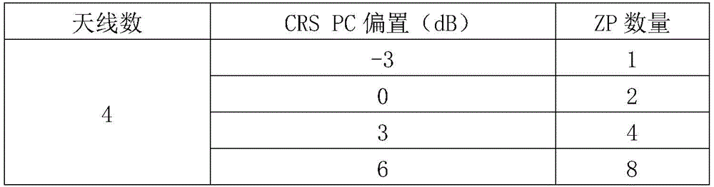
wherein, the value of the CRS PC bias is-3, which indicates that the power of the RE carrying RS is 0.5 times that of the RE carrying PDSCH, and the ZP number is 1; the CRS PC bias has a value of 0, which indicates that the power of the REs carrying the RS is 1 time that of the REs carrying the PDSCH, and the ZP number is 2; the CRS PC bias has a value of 3, which indicates that the power of the REs carrying the RS is 2 times that of the REs carrying the PDSCH, and the ZP number is 4; the CRS PC bias has a value of 6, indicating that the power of the REs carrying the RS is 4 times the power of the REs carrying the PDSCH, and the ZP number is 8.
In the embodiment of the present application, after CsirsReNum is obtained, the power control factor (unit dB) of the RE carrying PDSCH may be calculated:
RePwrFactor=10^(12/(12-CsirsReNum))
for example, csirsrenum=4, then repwrfactor=10×log 10 (12/(12-CsinReNum)). Apprxeq.1.76 dB, i.e., 1.5 times. Then, the NR function module allocates 1.5 times of the power of 33.33 to each of the 8 REs, that is, 33.33×1.5=50, to complete the power allocation of each RE in the symbol of the NR carrier.
208. The terminal device performs corresponding demodulation according to the puncturing pattern of the NR carrier.
In this embodiment of the present application, after the terminal device receives the puncturing pattern of the NR carrier sent by the NR functional module, corresponding demodulation may be performed according to the RE-level puncturing pattern of the NR carrier.
In some possible implementations, simulation experiments may be set up. It is assumed that users are evenly distributed in 10 megacells (M). The power offset of the REs carrying RSs in the LTE carrier is 3dB relative to the REs carrying PDSCH of the same symbol (i.e. the power of the former is 2 times the power of the latter). If the LTE carrier shares 66% of power for the NR carrier, the cell throughput rate under the NR carrier in the simulation experiment is 34.29Mbps. If the LTE carrier shares 100% power for the NR carrier, the cell throughput rate under the NR carrier in the simulation experiment is 42.81Mbps, and the gain is 24.85% = (42.81-34.29)/34.29. The resource loss after puncturing the NR carrier is 16 (number of ZPs)/(12×12 (total number of REs in a single symbol))=11.1%, so the overall gain is 24.85% -11.11% =13.75%.
The wireless access device comprises an NR functional module and an LTE functional module, wherein the NR functional module and the LTE functional module share a radio frequency channel. The NR functional module firstly acquires a cell reference signal pattern of the LTE carrier, and then determines a puncturing pattern of the NR carrier according to the cell reference signal pattern of the LTE carrier, even if the power of some RE of the symbols in the NR carrier is 0, the NR functional module acquires the shared power of the LTE carrier, and performs power distribution on the NR carrier according to the puncturing pattern of the NR carrier and the shared power, so that the equal power density among the symbols of the NR carrier is ensured.
For example, referring to fig. 3, an embodiment two of a power sharing method provided in the present application is to be explained, where the embodiment two is applied to a terminal device storing a cell reference signal of an LTE carrier. An exemplary power sharing method of the second embodiment includes the following steps:
301. the LTE functional module adds the LTE carrier into the power sharing group.
302. The NR function module adds an NR carrier to the power-sharing group.
303. The LTE functional module sends a cell reference signal pattern of the LTE carrier to the NR functional module.
Steps 301-303 are identical to steps 201-203 and are not described in detail herein.
304. And the LTE functional module shares the idle power of the LTE carrier to the NR carrier in the shared group.
Please refer to step 205, which is not described herein.
305. The NR function module sends a puncturing request of an NR carrier wave to the terminal equipment, wherein the puncturing request comprises the number of antenna ports.
In the embodiment of the present application, since the cell reference signal pattern of the LTE carrier is stored in the terminal device, when a puncturing request including the number of NR carriers of the antenna ports sent by the NR function module is received, the terminal device may perform puncturing according to the cell reference signal pattern of the LTE carrier. For a specific puncturing method, please refer to the puncturing method of the NR function module pair in step 204, which is not described herein.
306. The NR functional module performs power allocation on the shared power according to the puncturing pattern of the NR carrier.
307. The terminal device performs corresponding demodulation according to the puncturing pattern of the NR carrier.
Steps 306-307 are identical to steps 207-208 and are not described in detail herein.
The wireless access device comprises an NR functional module and an LTE functional module, wherein the NR functional module and the LTE functional module share a radio frequency channel. The NR functional module firstly acquires a cell reference signal pattern of the LTE carrier, and then determines a puncturing pattern of the NR carrier according to the cell reference signal pattern of the LTE carrier, even if the power of some RE of the symbols in the NR carrier is 0, the NR functional module acquires the shared power of the LTE carrier, and performs power distribution on the NR carrier according to the puncturing pattern of the NR carrier and the shared power, so that the equal power density among the symbols of the NR carrier is ensured.
It should be noted that, for simplicity of description, the foregoing method embodiments are all expressed as a series of action combinations, but it should be understood by those skilled in the art that the present application is not limited by the order of actions described, as some steps may be performed in other order or simultaneously in accordance with the present application. Further, those skilled in the art will also appreciate that the embodiments described in the specification are all preferred embodiments, and that the acts and modules referred to are not necessarily required in the present application.
In order to facilitate better implementation of the above-described aspects of the embodiments of the present application, the following further provides related devices for implementing the above-described aspects.
The embodiment of the present application provides a wireless access device, where the wireless access device includes an NR functional module and an LTE functional module, where the NR functional module and the LTE functional module share a radio frequency channel, as shown in fig. 4, and the NR functional module 400 includes: an acquisition unit 401 and a processing unit 402,
an obtaining unit 401, configured to obtain a cell reference signal pattern of an LTE carrier in the LTE functional module;
a processing unit 402, configured to determine a puncturing pattern of an NR carrier according to a cell reference signal pattern of the LTE carrier;
An obtaining unit 401, configured to obtain a shared power of the LTE carrier;
and a processing unit 402, configured to perform power allocation on the NR carrier according to the puncturing pattern of the NR carrier and the shared power.
In some possible implementations, the obtaining unit 401 is further configured to send the puncturing pattern of the NR carrier to a terminal device.
In some possible implementations, the processing unit 402 is further configured to add the NR carrier to a power sharing group, where the power sharing group includes LTE carriers.
In some possible implementations, the puncturing pattern of the NR carrier includes a first target symbol of the carrier having zero power ZP, a number of ZPs in the first target symbol, and/or a code division mapping manner.
In some possible implementations, the processing unit 402 is specifically configured to: allocating unit power for each resource element RE except ZP in the first target symbol, wherein the unit power is a quotient obtained by dividing the shared power by the number of RE in the first target symbol; setting the power of RE occupied by ZP in the first target symbol to be 0; and allocating additional power to each resource element RE except ZP in the first target symbol, multiplying the additional power by the product of the number of ZP, and allocating unit power for each resource element RE except ZP in the first target symbol by the shared power.
In some possible implementations, the obtaining unit 401 is further configured to obtain puncturing patterns of a plurality of preset NR carriers; the processing unit is further configured to select, according to the cell reference signal pattern of the LTE carrier, one from among the puncturing patterns of the plurality of preset NR carriers, as the puncturing pattern of the NR carrier.
In some possible implementations, the cell reference signal pattern of the LTE carrier includes a second target symbol of the LTE carrier carrying reference signals RSs, and power occupied by each RS on the second target symbol.
The embodiment of the present application provides a wireless access device, where the wireless access device includes an NR function module and an LTE function module, where the NR function module and the LTE function module share a radio frequency channel, as shown in fig. 5, and the LTE function module 500 includes: a transceiver unit 501 and a processing unit 502,
a transceiver unit 501, configured to send a cell reference signal pattern of an LTE carrier to the NR functional module;
and the processing unit 502 is configured to share the idle power of the LTE carrier to the NR functional module.
In some possible implementations, the processing unit 502 is specifically configured to add the LTE carrier to a power-sharing group.
In some possible implementations, the cell reference signal pattern of the LTE carrier includes a second target symbol of the LTE carrier carrying reference signals RSs, and power occupied by each RS on the second target symbol.
It should be noted that, because the content of information interaction and execution process between the modules/units of the above-mentioned device is based on the same concept as the method embodiment of the present application, the technical effects brought by the content are the same as the method embodiment of the present application, and specific content can be referred to the description in the method embodiment shown in the foregoing application, which is not repeated here.
The embodiment of the application also provides a computer storage medium, wherein the computer storage medium stores a program, and the program executes part or all of the steps described in the embodiment of the method.
Next, another wireless access device provided in the embodiments of the present application is described, where the wireless access device includes an NR functional module and an LTE functional module, where the NR functional module and the LTE functional module share a radio frequency channel, and referring to fig. 6, a wireless access device 600 includes:
a receiver 601, a transmitter 602, a processor 603 and a memory 604. In some embodiments of the present application, the receiver 601, transmitter 602, processor 603, and memory 604 may be connected by a bus or other means, where a bus connection is exemplified in fig. 6.
The processor 603 controls the operation of the wireless access device, the processor 603 may also be referred to as a central processing unit (central processing unit, CPU). In a specific application, the various components of the wireless access device are coupled together by a bus system that may include a power bus, a control bus, a status signal bus, and the like, in addition to a data bus. For clarity of illustration, however, the various buses are referred to in the figures as bus systems.
The method disclosed in the embodiments of the present application may be applied to the processor 603 or implemented by the processor 603. The processor 603 may be an integrated circuit chip with signal processing capabilities. In implementation, the steps of the above method may be performed by integrated logic circuitry of hardware in the processor 603 or instructions in the form of software. The processor 603 may be a general purpose processor, a digital signal processor (digital signal processing, DSP), an application specific integrated circuit (application specific integrated circuit, ASIC), a field-programmable gate array (field-programmable gate array, FPGA) or other programmable logic device, discrete gate or transistor logic device, discrete hardware components. The disclosed methods, steps, and logic blocks in the embodiments of the present application may be implemented or performed. A general purpose processor may be a microprocessor or the processor may be any conventional processor or the like. The steps of a method disclosed in connection with the embodiments of the present application may be embodied directly in hardware, in a decoded processor, or in a combination of hardware and software modules in a decoded processor. The software modules may be located in a random access memory, flash memory, read only memory, programmable read only memory, or electrically erasable programmable memory, registers, etc. as well known in the art. The storage medium is located in the memory 604, and the processor 603 reads information in the memory 604, and in combination with its hardware, performs the steps of the method described above.
In this embodiment, the processor 603 is configured to execute the power sharing method executed by the wireless access device.
In another possible design, when the wireless access device is a chip, the method includes: a processing unit, which may be, for example, a processor, and a communication unit, which may be, for example, an input/output interface, pins or circuitry, etc. The processing unit may execute the computer-executable instructions stored in the storage unit to cause the chip in the terminal to perform the method for transmitting wireless report information according to any one of the above first aspects. Alternatively, the storage unit is a storage unit in the chip, such as a register, a cache, or the like, and the storage unit may also be a storage unit in the terminal located outside the chip, such as a read-only memory (ROM) or other type of static storage device that may store static information and instructions, a random access memory (random access memory, RAM), or the like.
The processor mentioned in any of the above may be a general-purpose central processing unit, a microprocessor, an ASIC, or one or more integrated circuits for controlling the execution of the programs of the above method.
It should be further noted that the above-described apparatus embodiments are merely illustrative, and that the units described as separate units may or may not be physically separate, and that units shown as units may or may not be physical units, may be located in one place, or may be distributed over a plurality of network units. Some or all of the modules may be selected according to actual needs to achieve the purpose of the solution of this embodiment. In addition, in the drawings of the embodiment of the device provided by the application, the connection relation between the modules represents that the modules have communication connection therebetween, and can be specifically implemented as one or more communication buses or signal lines.
From the above description of the embodiments, it will be apparent to those skilled in the art that the present application may be implemented by means of software plus necessary general purpose hardware, or of course may be implemented by dedicated hardware including application specific integrated circuits, dedicated CPUs, dedicated memories, dedicated components and the like. Generally, functions performed by computer programs can be easily implemented by corresponding hardware, and specific hardware structures for implementing the same functions can be varied, such as analog circuits, digital circuits, or dedicated circuits. However, a software program implementation is a preferred embodiment in many cases for the present application. Based on such understanding, the technical solution of the present application may be embodied essentially or in a part contributing to the prior art in the form of a software product stored in a readable storage medium, such as a floppy disk, a usb disk, a removable hard disk, a ROM, a RAM, a magnetic disk or an optical disk of a computer, etc., including several instructions to cause a computer device (which may be a personal computer, a server, or a network device, etc.) to perform the method described in the embodiments of the present application.
In the above embodiments, it may be implemented in whole or in part by software, hardware, firmware, or any combination thereof. When implemented in software, may be implemented in whole or in part in the form of a computer program product.
The computer program product includes one or more computer instructions. When loaded and executed on a computer, produces a flow or function in accordance with embodiments of the present application, in whole or in part. The computer may be a general purpose computer, a special purpose computer, a computer network, or other programmable apparatus. The computer instructions may be stored in a computer-readable storage medium or transmitted from one computer-readable storage medium to another computer-readable storage medium, for example, the computer instructions may be transmitted from one website, computer, server, or data center to another website, computer, server, or data center by a wired (e.g., coaxial cable, fiber optic, digital Subscriber Line (DSL)) or wireless (e.g., infrared, wireless, microwave, etc.). The computer readable storage medium may be any available medium that can be stored by a computer or a data storage device such as a server, data center, etc. that contains an integration of one or more available media. The usable medium may be a magnetic medium (e.g., a floppy Disk, a hard Disk, a magnetic tape), an optical medium (e.g., a DVD), or a semiconductor medium (e.g., a Solid State Disk (SSD)), or the like.
Claims (25)
1. A power sharing method, characterized by being used for a wireless access device, wherein the wireless access device comprises a new air interface NR functional module and a long term evolution LTE functional module, and the NR functional module and the LTE functional module share a radio frequency channel, the method comprising:
the NR functional module acquires a cell reference signal pattern of an LTE carrier in the LTE functional module;
the NR functional module determines a puncturing pattern of an NR carrier according to the cell reference signal pattern of the LTE carrier;
the NR functional module acquires the shared power of the LTE carrier;
and the NR functional module distributes power to the NR carrier according to the puncturing pattern of the NR carrier and the shared power.
2. The method of claim 1 wherein the NR function module, after determining the puncturing pattern for the NR carrier based on the cell reference signal pattern for the LTE carrier, further comprises:
and the NR functional module sends the puncturing pattern of the NR carrier wave to terminal equipment.
3. The method according to claim 1 or 2, wherein before the NR function module determines the puncturing pattern for the NR carrier from the cell reference signal pattern for the LTE carrier, the method further comprises:
The NR function module adds the NR carrier to a power sharing group, the power sharing group comprising LTE carriers.
4. A method according to any of claims 1-3, characterized in that the puncturing pattern of the NR carrier comprises a first target symbol with zero power ZP in the carrier, the number of ZPs in the first target symbol and/or the code division mapping.
5. The method of claim 4 wherein the NR function module performing power allocation for the NR carrier based on the puncturing pattern for the NR carrier and the shared power comprises:
the NR functional module allocates unit power for each resource element RE except ZP in the first target symbol, wherein the unit power is a quotient obtained by dividing the shared power by the number of RE in the first target symbol;
the NR power module sets the power of RE occupied by ZP in the first target symbol to 0;
the NR functional module allocates additional power to each resource element RE except ZP in the first target symbol, multiplies the product of the number of ZP by the additional power, and allocates unit power to each resource element RE except ZP in the first target symbol for the shared power.
6. The method according to any of claims 1-5, wherein the NR function module determining a puncturing pattern for an NR carrier from a cell reference signal pattern for the LTE carrier comprises:
the NR functional module acquires punching patterns of a plurality of preset NR carriers;
and the NR functional module selects one from the punching patterns of the plurality of preset NR carriers according to the cell reference signal pattern of the LTE carrier as the punching pattern of the NR carrier.
7. The method according to any of claims 1-6, wherein the cell reference signal pattern of the LTE carrier includes a second target symbol of the LTE carrier carrying reference signal RSs, and power occupied by each RS on the second target symbol.
8. A power sharing method, characterized by being used for a wireless access device, the wireless access device comprising an NR functional module and an LTE functional module, the NR functional module and the LTE functional module sharing a radio frequency channel, the method comprising:
the LTE functional module sends a cell reference signal pattern of an LTE carrier to the NR functional module;
and the LTE functional module shares the idle power of the LTE carrier to the NR functional module.
9. The method of claim 8, wherein before the LTE functional module sends the cell reference signal pattern of the LTE carrier to the NR functional module, further comprising:
the LTE functional module adds the LTE carrier to a power sharing group.
10. The method according to claim 8 or 9, wherein the cell reference signal pattern of the LTE carrier includes a second target symbol of the LTE carrier carrying reference signal RS, and power occupied by each RS on the second target symbol.
11. The wireless access device is characterized by comprising an NR functional module and an LTE functional module, wherein the NR functional module and the LTE functional module share a radio frequency channel, and the NR functional module comprises:
an obtaining unit, configured to obtain a cell reference signal pattern of an LTE carrier in the LTE functional module;
a processing unit, configured to determine a puncturing pattern of an NR carrier according to a cell reference signal pattern of the LTE carrier;
the acquiring unit is configured to acquire a shared power of the LTE carrier;
and the processing unit is used for carrying out power distribution on the NR carrier according to the puncturing pattern of the NR carrier and the shared power.
12. The wireless access device of claim 11, further comprising:
and the receiving and transmitting unit is used for transmitting the puncturing pattern of the NR carrier wave to the terminal equipment.
13. The wireless access device of claim 11 or 12, wherein,
the processing unit is further configured to add the NR carrier to a power sharing group, where the power sharing group includes LTE carriers.
14. The wireless access device according to any of claims 11-13, wherein the puncturing pattern for the NR carrier comprises a first target symbol in the carrier with zero power ZP, a number of ZPs in the first target symbol and/or a code division mapping manner.
15. The wireless access device of claim 14, wherein the processing unit is specifically configured to:
allocating unit power for each resource element RE except ZP in the first target symbol, wherein the unit power is a quotient obtained by dividing the shared power by the number of RE in the first target symbol;
setting the power of RE occupied by ZP in the first target symbol to be 0;
and allocating additional power to each resource element RE except ZP in the first target symbol, multiplying the additional power by the product of the number of ZP, and allocating unit power for each resource element RE except ZP in the first target symbol by the shared power.
16. The wireless access device according to any of the claims 11-15, characterized in that,
the acquisition unit is further used for acquiring punching patterns of a plurality of preset NR carriers;
the processing unit is further configured to select, according to the cell reference signal pattern of the LTE carrier, one from among the puncturing patterns of the plurality of preset NR carriers, as the puncturing pattern of the NR carrier.
17. The wireless access device according to any of claims 11-16, wherein the cell reference signal pattern of the LTE carrier includes a second target symbol of the LTE carrier carrying reference signal RSs, and power occupied by each RS on the second target symbol.
18. The utility model provides a power sharing wireless access device which characterized in that, wireless access device includes NR function module and LTE function module, NR function module with LTE function module sharing radio frequency channel, LTE function module includes:
a transceiver unit, configured to send a cell reference signal pattern of an LTE carrier to the NR functional module;
and the processing unit is used for sharing the idle power of the LTE carrier to the NR functional module.
19. The wireless access device of claim 18, wherein,
The processing unit is specifically configured to add the LTE carrier to a power sharing group.
20. The wireless access device of claim 18 or 19, wherein the cell reference signal pattern of the LTE carrier includes a second target symbol of the LTE carrier carrying reference signal RSs, and power occupied by each RS on the second target symbol.
21. A wireless access device, comprising: an NR function module and an LTE function module, wherein,
the NR function module for performing the method of any one of the preceding claims 1-7;
the LTE functional module for performing the method of any one of the preceding claims 8-10.
22. A computer readable storage medium, characterized in that the computer readable storage medium stores a program that causes a computer device to perform the method of any one of claims 1-10.
23. A computer program product, the computer program product comprising computer-executable instructions stored on a computer-readable storage medium; at least one processor of a device reads the computer-executable instructions from the computer-readable storage medium, the at least one processor executing the computer-executable instructions causing the device to perform the method of any one of claims 1-10.
24. A communication device comprising at least one processor, a memory, and a communication interface;
the at least one processor is coupled with the memory and the communication interface;
the memory is used for storing instructions, the processor is used for executing the instructions, and the communication interface is used for communicating with other communication devices under the control of the at least one processor;
the instructions, when executed by the at least one processor, cause the at least one processor to perform the method of any of claims 1-10.
25. A chip system, characterized in that it comprises a processor and a memory, said memory and said processor being interconnected by wires, said memory having instructions stored therein, said processor being adapted to perform the method according to any of claims 1-10.
Priority Applications (1)
| Application Number | Priority Date | Filing Date | Title |
|---|---|---|---|
| CN202111275664.5A CN116074941B (en) | 2021-10-29 | 2021-10-29 | A power sharing method and a wireless access device |
Applications Claiming Priority (1)
| Application Number | Priority Date | Filing Date | Title |
|---|---|---|---|
| CN202111275664.5A CN116074941B (en) | 2021-10-29 | 2021-10-29 | A power sharing method and a wireless access device |
Publications (2)
| Publication Number | Publication Date |
|---|---|
| CN116074941A true CN116074941A (en) | 2023-05-05 |
| CN116074941B CN116074941B (en) | 2025-11-25 |
Family
ID=86177273
Family Applications (1)
| Application Number | Title | Priority Date | Filing Date |
|---|---|---|---|
| CN202111275664.5A Active CN116074941B (en) | 2021-10-29 | 2021-10-29 | A power sharing method and a wireless access device |
Country Status (1)
| Country | Link |
|---|---|
| CN (1) | CN116074941B (en) |
Citations (8)
| Publication number | Priority date | Publication date | Assignee | Title |
|---|---|---|---|---|
| CN101808396A (en) * | 2010-03-24 | 2010-08-18 | 华为技术有限公司 | Power sharing method and base station |
| CN101969646A (en) * | 2009-07-28 | 2011-02-09 | 鼎桥通信技术有限公司 | Carrier power sharing method and device of multi-frequency band mixed cell |
| CN102845009A (en) * | 2010-01-14 | 2012-12-26 | 高通股份有限公司 | Channel feedback based on reference signal |
| CN105491665A (en) * | 2014-09-15 | 2016-04-13 | 中兴通讯股份有限公司 | Pilot frequency configuration method and device |
| WO2017196065A1 (en) * | 2016-05-10 | 2017-11-16 | 엘지전자 주식회사 | Method for controlling uplink transmission power in wireless communication system and device therefor |
| WO2020251426A1 (en) * | 2019-06-10 | 2020-12-17 | Telefonaktiebolaget Lm Ericsson (Publ) | Uplink power control of a terminal device |
| CN112425214A (en) * | 2018-07-27 | 2021-02-26 | 华为技术有限公司 | Method and apparatus for power sharing |
| CN113347696A (en) * | 2020-03-02 | 2021-09-03 | 华为技术服务有限公司 | Power distribution method and device |
-
2021
- 2021-10-29 CN CN202111275664.5A patent/CN116074941B/en active Active
Patent Citations (9)
| Publication number | Priority date | Publication date | Assignee | Title |
|---|---|---|---|---|
| CN101969646A (en) * | 2009-07-28 | 2011-02-09 | 鼎桥通信技术有限公司 | Carrier power sharing method and device of multi-frequency band mixed cell |
| CN102845009A (en) * | 2010-01-14 | 2012-12-26 | 高通股份有限公司 | Channel feedback based on reference signal |
| CN101808396A (en) * | 2010-03-24 | 2010-08-18 | 华为技术有限公司 | Power sharing method and base station |
| CN105491665A (en) * | 2014-09-15 | 2016-04-13 | 中兴通讯股份有限公司 | Pilot frequency configuration method and device |
| WO2017196065A1 (en) * | 2016-05-10 | 2017-11-16 | 엘지전자 주식회사 | Method for controlling uplink transmission power in wireless communication system and device therefor |
| CN112425214A (en) * | 2018-07-27 | 2021-02-26 | 华为技术有限公司 | Method and apparatus for power sharing |
| WO2020251426A1 (en) * | 2019-06-10 | 2020-12-17 | Telefonaktiebolaget Lm Ericsson (Publ) | Uplink power control of a terminal device |
| CN113347696A (en) * | 2020-03-02 | 2021-09-03 | 华为技术服务有限公司 | Power distribution method and device |
| WO2021174960A1 (en) * | 2020-03-02 | 2021-09-10 | 华为技术有限公司 | Power allocation method and device |
Non-Patent Citations (1)
| Title |
|---|
| NTT等: ""R1-1709712_WF on UL power sharing between LTE and NR_v9"", 3GPP TSG_RAN\\WG1_RL1, 19 May 2017 (2017-05-19) * |
Also Published As
| Publication number | Publication date |
|---|---|
| CN116074941B (en) | 2025-11-25 |
Similar Documents
| Publication | Publication Date | Title |
|---|---|---|
| JP2023123583A (en) | User terminal and wireless communication method | |
| US11882518B2 (en) | Control information transmission method, base station, and terminal | |
| JP2021170787A (en) | Communication device and communication method | |
| EP4561219A1 (en) | Tci state indication method and apparatus, and storage medium | |
| CN110831020A (en) | Method for detecting DCI (Downlink control information), method for configuring PDCCH (physical Downlink control channel) and communication device | |
| US11432273B2 (en) | Control information sending method, control information receiving method, access network device, and terminal device | |
| US20240121024A1 (en) | Method and apparatus for determining modulation and coding scheme mcs table | |
| CN115567890A (en) | Communication method and communication device | |
| CN112752259B (en) | Terminal type determining method, network equipment and terminal | |
| CN116671213A (en) | Method and device for determining transmission power | |
| CN112243596B (en) | Method, device, terminal and medium for sending DMRS | |
| CN114337948B (en) | Reference signal configuration method, antenna switching method, device and storage medium | |
| CN110944398B (en) | Resource processing method and related equipment | |
| WO2021129522A1 (en) | Uplink control information transmission method, terminal device, and network side device | |
| CN116074941B (en) | A power sharing method and a wireless access device | |
| CN112153690A (en) | Communication method and communication device | |
| CN107592189B (en) | Transmission method, user equipment and base station | |
| CN114391231B (en) | Communication method and communication device | |
| CN119096643A (en) | Simultaneous PUSCH transmission on multiple panels | |
| KR102430394B1 (en) | Information transmission method and device | |
| CN112055996B (en) | A method and device for information transmission | |
| KR102367157B1 (en) | Reference signal transmission method, terminal and network device | |
| US12225544B2 (en) | Information determination method and apparatus, device, and storage medium | |
| EP4535702A1 (en) | Communication method and apparatus, and storage medium | |
| US12200699B2 (en) | Physical downlink control channel candidate resource mapping and transmission for multi-TRP operation |
Legal Events
| Date | Code | Title | Description |
|---|---|---|---|
| PB01 | Publication | ||
| PB01 | Publication | ||
| SE01 | Entry into force of request for substantive examination | ||
| SE01 | Entry into force of request for substantive examination | ||
| GR01 | Patent grant | ||
| GR01 | Patent grant |