[go: up one dir, main page]

CN116057491A - remote control device - Google Patents

remote control device Download PDF

Info

Publication number
CN116057491A
CN116057491A CN202180056325.XA CN202180056325A CN116057491A CN 116057491 A CN116057491 A CN 116057491A CN 202180056325 A CN202180056325 A CN 202180056325A CN 116057491 A CN116057491 A CN 116057491A
Authority
CN
China
Prior art keywords
remote control
control device
base portion
insert member
vehicle
Prior art date
Legal status (The legal status is an assumption and is not a legal conclusion. Google has not performed a legal analysis and makes no representation as to the accuracy of the status listed.)
Pending
Application number
CN202180056325.XA
Other languages
Chinese (zh)
Inventor
T·M·卢斯曼
S·R·普尔斯坎普
V·I·伍德拉夫三世
D·T·麦克马努斯
J·S·弗拉迪
M·E·温宁
Current Assignee (The listed assignees may be inaccurate. Google has not performed a legal analysis and makes no representation or warranty as to the accuracy of the list.)
Crown Equipment Corp
Original Assignee
Crown Equipment Corp
Priority date (The priority date is an assumption and is not a legal conclusion. Google has not performed a legal analysis and makes no representation as to the accuracy of the date listed.)
Filing date
Publication date
Application filed by Crown Equipment Corp filed Critical Crown Equipment Corp
Publication of CN116057491A publication Critical patent/CN116057491A/en
Pending legal-status Critical Current

Links

Images

Classifications

    • GPHYSICS
    • G05CONTROLLING; REGULATING
    • G05DSYSTEMS FOR CONTROLLING OR REGULATING NON-ELECTRIC VARIABLES
    • G05D1/00Control of position, course, altitude or attitude of land, water, air or space vehicles, e.g. using automatic pilots
    • G05D1/0011Control of position, course, altitude or attitude of land, water, air or space vehicles, e.g. using automatic pilots associated with a remote control arrangement
    • G05D1/0016Control of position, course, altitude or attitude of land, water, air or space vehicles, e.g. using automatic pilots associated with a remote control arrangement characterised by the operator's input device
    • GPHYSICS
    • G08SIGNALLING
    • G08CTRANSMISSION SYSTEMS FOR MEASURED VALUES, CONTROL OR SIMILAR SIGNALS
    • G08C17/00Arrangements for transmitting signals characterised by the use of a wireless electrical link
    • G08C17/02Arrangements for transmitting signals characterised by the use of a wireless electrical link using a radio link
    • GPHYSICS
    • G05CONTROLLING; REGULATING
    • G05DSYSTEMS FOR CONTROLLING OR REGULATING NON-ELECTRIC VARIABLES
    • G05D1/00Control of position, course, altitude or attitude of land, water, air or space vehicles, e.g. using automatic pilots
    • G05D1/0011Control of position, course, altitude or attitude of land, water, air or space vehicles, e.g. using automatic pilots associated with a remote control arrangement
    • G05D1/0033Control of position, course, altitude or attitude of land, water, air or space vehicles, e.g. using automatic pilots associated with a remote control arrangement by having the operator tracking the vehicle either by direct line of sight or via one or more cameras located remotely from the vehicle
    • BPERFORMING OPERATIONS; TRANSPORTING
    • B66HOISTING; LIFTING; HAULING
    • B66FHOISTING, LIFTING, HAULING OR PUSHING, NOT OTHERWISE PROVIDED FOR, e.g. DEVICES WHICH APPLY A LIFTING OR PUSHING FORCE DIRECTLY TO THE SURFACE OF A LOAD
    • B66F9/00Devices for lifting or lowering bulky or heavy goods for loading or unloading purposes
    • B66F9/06Devices for lifting or lowering bulky or heavy goods for loading or unloading purposes movable, with their loads, on wheels or the like, e.g. fork-lift trucks
    • B66F9/075Constructional features or details
    • B66F9/07581Remote controls

Landscapes

  • Engineering & Computer Science (AREA)
  • Physics & Mathematics (AREA)
  • General Physics & Mathematics (AREA)
  • Automation & Control Theory (AREA)
  • Remote Sensing (AREA)
  • Radar, Positioning & Navigation (AREA)
  • Aviation & Aerospace Engineering (AREA)
  • Computer Networks & Wireless Communication (AREA)
  • Transportation (AREA)
  • Structural Engineering (AREA)
  • Theoretical Computer Science (AREA)
  • Mathematical Physics (AREA)
  • Computing Systems (AREA)
  • Mechanical Engineering (AREA)
  • Geology (AREA)
  • Life Sciences & Earth Sciences (AREA)
  • Civil Engineering (AREA)
  • Selective Calling Equipment (AREA)
  • Control Of Position, Course, Altitude, Or Attitude Of Moving Bodies (AREA)

Abstract

A remote control device to be worn on an operator's limb includes a base portion, a wireless communication system, a control, and an insert member. The wireless communication system includes a wireless transmitter for transmitting wireless commands from a remote control device. The control is communicatively coupled to the wireless communication system, wherein actuation of the control causes the wireless transmitter to transmit a wireless command. The insert member is removably attached to the base portion.

Description

远程控制设备remote control device

技术领域technical field

本文公开的实施例涉及远程控制设备,诸如可以由与物料搬运车辆(materialshandling vehicle)交互的操作者使用。Embodiments disclosed herein relate to remote control devices, such as may be used by operators interacting with materials handling vehicles.

背景技术Background technique

物料搬运车辆(materials handling vehicle)通常用于在仓库和配送中心拣货。此类车辆通常包括动力单元和负载搬运组件,负载搬运组件可以包括装载货叉(loadcarrying fork)。车辆还具有用于控制车辆的操作和移动的控制结构。Materials handling vehicles are commonly used for picking goods in warehouses and distribution centers. Such vehicles typically include a power unit and a load handling assembly, which may include a loadcarrying fork. The vehicle also has a control structure for controlling the operation and movement of the vehicle.

在典型的拣货操作中,操作者从位于沿着仓库或配送中心的一个或多个过道提供的存储区域中的可用库存项目填写订单。操作者在要拣选的(一个或多个)物品的各个拣选位置之间驾驶车辆。操作者可以或者通过使用车辆上的控制结构或者经由与车辆相关联的无线远程控制设备(诸如在共同拥有的美国专利No.9,082,293中公开的远程控制设备,该专利的全部公开内容通过引用并入本文)来驾驶车辆。In a typical picking operation, operators fill orders from available inventory items located in storage areas provided along one or more aisles of a warehouse or distribution center. An operator drives the vehicle between various pick locations for the item(s) to be picked. The operator can either use the control structure on the vehicle or via a wireless remote control device associated with the vehicle, such as the remote control device disclosed in commonly owned U.S. Patent No. 9,082,293, the entire disclosure of which is incorporated by reference. This article) to drive the vehicle.

发明内容Contents of the invention

根据第一方面,一种远程控制设备包括:基座部分;无线通信系统,包括用于从远程控制设备发送无线命令的无线发送器;控件,可通信地耦合到无线通信系统,其中控件的致动使得无线发送器发送无线命令;耦合到基座部分的固定结构,其中固定结构限定用于接纳操作者的肢体(appendage)的开口;以及插入构件,附接到基座部分或固定结构中的至少一个,其中插入构件实现开口尺寸的减小。According to a first aspect, a remote control device includes: a base portion; a wireless communication system including a wireless transmitter for transmitting wireless commands from the remote control device; a fixed structure coupled to the base portion, wherein the fixed structure defines an opening for receiving an operator's appendage; and an insertion member attached to the base portion or the fixed structure. At least one wherein the insertion member achieves a reduction in the size of the opening.

固定结构可以包括固定部分和耦合到基座部分的紧固件部分,其中开口限定在固定部分与基座部分或插入构件中的至少一个之间。插入构件可以包括在其端部分处的凹口以接纳固定结构的固定部分。The securing structure may include a securing portion and a fastener portion coupled to the base portion, wherein an opening is defined between the securing portion and at least one of the base portion or the insertion member. The insertion member may comprise a notch at an end portion thereof to receive a fixation portion of the fixation structure.

插入构件可以可移除地附接到基座部分。The insert member may be removably attachable to the base portion.

插入构件可以具有与基座部分不同的纹理。The insert member may have a different texture than the base portion.

插入构件可以由可膨胀材料形成,使得插入构件可以被拉伸以增加开口的尺寸。The insertion member can be formed from an expandable material such that the insertion member can be stretched to increase the size of the opening.

插入构件可以由摩擦系数高于基座部分的材料形成。插入构件可以由硬度低于基座部分的材料形成。插入构件可以由压缩率高于基座部分的材料形成;以及/或者,插入构件可以由透气性高于基座部分的材料形成。The insertion member may be formed of a material having a higher coefficient of friction than the base portion. The insertion member may be formed of a material having a hardness lower than that of the base portion. The insert member may be formed from a material that has a higher compressibility than the base portion; and/or, the insert member may be formed from a material that is more gas permeable than the base portion.

多个表面特征可以从插入构件的内表面向外或向内中的至少一个延伸。表面特征可以包括肋、穿孔、凹坑、突起、脊、通道或粗糙区域中的至少一种。The plurality of surface features may extend at least one of outwardly or inwardly from the inner surface of the insertion member. Surface features may include at least one of ribs, perforations, dimples, protrusions, ridges, channels, or roughened areas.

插入构件可以包括外表面,该外表面接合基座部分的对应形状的内表面以在插入构件和基座部分之间形成紧密配合。The insertion member may include an outer surface that engages a correspondingly shaped inner surface of the base portion to form a tight fit between the insertion member and the base portion.

肢体可以包括操作者的手的一个或多个手指。The limb may include one or more fingers of the operator's hand.

插入构件可以选自多个插入构件,多个插入构件中的每个插入构件具有与其它插入构件不同的尺寸、形状、纹理、硬度、透气性、压缩性或摩擦系数中的至少一个。The insertion member may be selected from a plurality of insertion members each having at least one of a different size, shape, texture, hardness, air permeability, compressibility, or coefficient of friction than the other insertion members.

根据第二方面,一种远程控制设备包括:基座部分;无线通信系统,包括用于从远程控制设备发送无线命令的无线发送器;控件,可通信地耦合到无线通信系统,其中控件的致动使得无线发送器发送无线命令;以及附接至基座部分的插入构件。用于接纳操作者的肢体的开口被限定为以下之一:在基座部分和插入构件之间;或由插入构件限定。插入构件由可膨胀材料形成,使得插入构件可以被拉伸以增加开口的尺寸。According to a second aspect, a remote control device includes: a base portion; a wireless communication system including a wireless transmitter for transmitting wireless commands from the remote control device; a control communicatively coupled to the wireless communication system, wherein the control's actuating the wireless transmitter to send wireless commands; and an insertion member attached to the base portion. The opening for receiving the operator's limb is defined as one of: between the base portion and the insertion member; or by the insertion member. The insertion member is formed from an expandable material such that the insertion member can be stretched to increase the size of the opening.

插入构件可以包括圆柱形构件。The insertion member may comprise a cylindrical member.

插入构件可以包括接纳在基座部分中的对应槽中以将插入构件可移除地附接到基座部分的至少一个接片,和/或基座部分可以包括接纳在插入构件中的对应槽中以将插入构件可移除地附接到基座部分的至少一个接片。The insert member may include at least one tab received in a corresponding slot in the base portion to removably attach the insert member to the base portion, and/or the base portion may include a corresponding slot received in the insert member At least one tab for removably attaching the insert member to the base portion.

插入构件可以具有与基座部分不同的纹理。插入构件可以由摩擦系数高于基座部分的材料形成。插入构件可以由硬度低于基座部分的材料形成。插入构件可以由压缩率高于基座部分的材料形成;以及/或者,插入构件可以由透气性高于基座部分的材料形成。The insert member may have a different texture than the base portion. The insertion member may be formed of a material having a higher coefficient of friction than the base portion. The insertion member may be formed of a material having a hardness lower than that of the base portion. The insert member may be formed from a material that has a higher compressibility than the base portion; and/or, the insert member may be formed from a material that is more gas permeable than the base portion.

多个表面特征可以从插入构件的内表面向外或向内中的至少一个延伸。表面特征可以包括肋、穿孔、凹坑、突起、脊、通道或粗糙区域中的至少一种。The plurality of surface features may extend at least one of outwardly or inwardly from the inner surface of the insertion member. Surface features may include at least one of ribs, perforations, dimples, protrusions, ridges, channels, or roughened areas.

插入构件可以包括外表面,该外表面接合基座部分的对应形状的内表面以在插入构件和基座部分之间形成紧密配合。The insertion member may include an outer surface that engages a correspondingly shaped inner surface of the base portion to form a tight fit between the insertion member and the base portion.

肢体可以包括操作者的手的一个或多个手指。The limb may include one or more fingers of the operator's hand.

插入构件可以选自多个插入构件,多个插入构件中的每个插入构件具有与其它插入构件不同的尺寸、形状、纹理、硬度、透气性、压缩性或摩擦系数中的至少一个。The insertion member may be selected from a plurality of insertion members each having at least one of a different size, shape, texture, hardness, air permeability, compressibility, or coefficient of friction than the other insertion members.

根据第三方面,一种远程控制设备包括:基座部分;无线通信系统,包括用于从远程控制设备发送无线命令的无线发送器;控件,可通信地耦合到无线通信系统,其中控件的致动使得无线发送器发送无线命令;以及选自多个插入构件的插入构件,多个插入构件中的每一个具有与其它插入构件不同的尺寸、形状、纹理、硬度、透气性、压缩性或摩擦系数中的至少一个。插入构件可移除地附接到基座部分,使得多个插入构件中的任何一个可以附接到基座部分以定制插入构件的尺寸、形状、纹理、硬度、透气性、压缩性或摩擦系数中的至少一个。用于接纳操作者的肢体的开口至少部分地由插入构件限定。According to a third aspect, a remote control device includes: a base portion; a wireless communication system including a wireless transmitter for sending wireless commands from the remote control device; a control communicatively coupled to the wireless communication system, wherein the control's causing the wireless transmitter to transmit wireless commands; and an insertion member selected from a plurality of insertion members, each of the plurality of insertion members having a different size, shape, texture, hardness, air permeability, compressibility, or friction from the other insertion members at least one of the coefficients. The insert member is removably attached to the base portion such that any of a plurality of insert members can be attached to the base portion to customize the size, shape, texture, hardness, air permeability, compressibility or coefficient of friction of the insert member at least one of the An opening for receiving an operator's limb is at least partially defined by the insertion member.

插入构件可以包括圆柱形构件。The insertion member may comprise a cylindrical member.

插入构件可以包括接纳在基座部分中的对应槽中以将插入构件可移除地附接到基座部分的至少一个接片,和/或基座部分可以包括接纳在插入构件中的对应槽中以将插入构件可移除地附接到基座部分的至少一个接片。The insert member may include at least one tab received in a corresponding slot in the base portion to removably attach the insert member to the base portion, and/or the base portion may include a corresponding slot received in the insert member At least one tab for removably attaching the insert member to the base portion.

插入构件可以具有与基座部分不同的纹理。插入构件可以由摩擦系数高于基座部分的材料形成。插入构件可以由硬度低于基座部分的材料形成。插入构件可以由压缩率高于基座部分的材料形成;以及/或者,插入构件可以由透气性高于基座部分的材料形成。The insert member may have a different texture than the base portion. The insertion member may be formed of a material having a higher coefficient of friction than the base portion. The insertion member may be formed of a material having a hardness lower than that of the base portion. The insert member may be formed from a material that has a higher compressibility than the base portion; and/or, the insert member may be formed from a material that is more gas permeable than the base portion.

多个表面特征可以从插入构件的内表面向外或向内中的至少一个延伸。表面特征可以包括肋、穿孔、凹坑、突起、脊、通道或粗糙区域中的至少一种。The plurality of surface features may extend at least one of outwardly or inwardly from the inner surface of the insertion member. Surface features may include at least one of ribs, perforations, dimples, protrusions, ridges, channels, or roughened areas.

插入构件可以包括外表面,该外表面与基座部分的对应形状的内表面接合以在插入构件和基座部分之间形成紧密配合。The insertion member may include an outer surface that engages a correspondingly shaped inner surface of the base portion to form a tight fit between the insertion member and the base portion.

肢体可以包括操作者的手的一个或多个手指。The limb may include one or more fingers of the operator's hand.

根据第四方面,一种远程控制设备包括:基座部分;无线通信系统,包括用于从远程控制设备发送无线命令的无线发送器;控件,可通信地耦合到无线通信系统,其中控件的致动使得无线发送器发送无线命令;固定结构,耦合到基座部分,其中开口由固定结构限定,用于接纳操作者的肢体;以及插入构件,可枢转地附接到基座部分。插入构件的枢转移动调整开口的尺寸。According to a fourth aspect, a remote control device includes: a base portion; a wireless communication system including a wireless transmitter for sending wireless commands from the remote control device; a control communicatively coupled to the wireless communication system, wherein the control's Actuation causes the wireless transmitter to transmit wireless commands; a fixed structure coupled to the base portion, wherein an opening is defined by the fixed structure for receiving an operator's limb; and an insertion member pivotally attached to the base portion. Pivotal movement of the insertion member adjusts the size of the opening.

插入构件可以使用至少一个紧固件可枢转地附接到基座部分。The insertion member may be pivotally attached to the base portion using at least one fastener.

固定结构可以包括固定部分和耦合到基座部分的紧固件部分,其中开口限定在基座部分和固定部分之间。The securing structure may include a securing portion and a fastener portion coupled to a base portion, wherein an opening is defined between the base portion and the securing portion.

插入构件可以包括接纳固定结构的固定部分的凹口。The insertion member may include a recess that receives the fixation portion of the fixation structure.

肢体可以包括操作者的手的一个或多个手指。The limb may include one or more fingers of the operator's hand.

附图说明Description of drawings

图1和图2是根据实施例的能够远程无线操作的物料搬运车辆的侧视图和顶视图;1 and 2 are side and top views of a material handling vehicle capable of remote wireless operation, according to an embodiment;

图2A是根据实施例的能够远程无线操作的另一个物料搬运车辆的侧视图;2A is a side view of another materials handling vehicle capable of remote wireless operation according to an embodiment;

图3是根据实施例的能够远程无线操作的物料搬运车辆的几个部件的示意图;3 is a schematic diagram of several components of a material handling vehicle capable of remote wireless operation, according to an embodiment;

图4-图7是根据实施例的远程控制设备的视图;4-7 are views of a remote control device according to an embodiment;

图8A和图8B是剖视图,示出了根据实施例的与充电站接合的远程控制设备;8A and 8B are cross-sectional views illustrating a remote control device engaged with a charging station, according to an embodiment;

图9和图10是根据实施例的另一个远程控制设备的视图;9 and 10 are views of another remote control device according to an embodiment;

图11是根据实施例的充电站的几个部件的示意图;11 is a schematic diagram of several components of a charging station, according to an embodiment;

图12-图14是示出根据实施例的远程控制设备和充电站的视图;12-14 are views showing a remote control device and a charging station according to an embodiment;

图15是根据实施例的远程控制设备的几个部件的示意图;Figure 15 is a schematic diagram of several components of a remote control device according to an embodiment;

图16描绘了根据实施例的方法;Figure 16 depicts a method according to an embodiment;

图17描绘了根据实施例的配对方法;Figure 17 depicts a pairing method according to an embodiment;

图18描绘了根据实施例的另一种配对方法;Figure 18 depicts another pairing method according to an embodiment;

图19描绘了根据实施例的用于重新配对车辆和远程控制设备的方法;Figure 19 depicts a method for re-pairing a vehicle and a remote control device, under an embodiment;

图20描绘了根据实施例在车辆和远程控制设备之间重新建立通信的方法;20 depicts a method of re-establishing communication between a vehicle and a remote control device, according to an embodiment;

图21描绘了根据实施例为远程控制设备充电的方法;Figure 21 depicts a method of charging a remote control device, according to an embodiment;

图22描绘了根据实施例为远程控制设备充电的另一种方法;Figure 22 depicts another method of charging a remote control device according to an embodiment;

图23是根据实施例的套件的几个部件的示意图;Figure 23 is a schematic illustration of several components of a kit according to an embodiment;

图24是根据实施例的另一个远程控制设备的视图;Fig. 24 is a view of another remote control device according to an embodiment;

图25是图示实施例的示意图;以及Figure 25 is a schematic diagram illustrating an embodiment; and

图26-图44是示出根据实施例的远程控制设备的视图。26-44 are views illustrating a remote control device according to an embodiment.

具体实施方式Detailed ways

下文阐述了本公开的许多不同实施例的广泛描述。该描述仅被解释为示例性的并且不描述每一个可能的实施例,因为描述每一个可能的实施例即使不是不可能也是不切实际的,并且应当理解本文描述的任何特征、特性、部件、组合物、成分、产品、步骤或方法可以全部或部分被删除、组合或替代本文描述的任何其它特征、特性、部件、组合物、成分、产品、步骤或方法。应该理解的是,设想了所描述和所示实施例的多种组合,并且对一个实施例的特别关注并不排除将其包括在其它所描述实施例的组合中。还可以使用当前技术或在本专利申请日之后开发的技术来实现许多替代实施例,这些仍然落入权利要求的范围内。本文引用的所有出版物和专利均通过引用并入本文。A broad description of many different embodiments of the disclosure is set forth below. This description is to be construed as exemplary only and does not describe every possible embodiment, since describing every possible embodiment would be impractical, if not impossible, and it is to be understood that any feature, characteristic, component, A composition, ingredient, product, step or method may be deleted, combined or substituted in whole or in part for any other feature, property, component, composition, ingredient, product, step or method described herein. It should be understood that various combinations of the described and illustrated embodiments are contemplated and that particular attention to one embodiment does not preclude its inclusion in combinations of other described embodiments. Numerous alternative embodiments could also be implemented, using either current technology or technology developed after the filing date of this patent, which would still fall within the scope of the claims. All publications and patents cited herein are hereby incorporated by reference.

低位拣货卡车low level pick truck

现在参考附图,尤其是图1和图2,被图示为低位拣货卡车(low level orderpicking truck)的物料搬运车辆10包括从动力单元14延伸的负载搬运组件12。车辆10形成根据实施例的系统8的一部分,下面将更全面地描述系统8。负载搬运组件12包括一对叉子16,每个叉子16具有负载支撑轮组件18。除了叉子16的图示布置之外或代替叉子16的图示布置,负载搬运组件12可以包括其它负载搬运特征,诸如负载靠背、剪刀式升降叉、外伸支架或单独的高度可调叉,仅举几个示例。更进一步,负载搬运组件12可以包括负载搬运特征,诸如桅杆、负载平台、收集笼或由叉子16承载或以其它方式提供用于搬运由车辆10支撑和承载的负载的其它支撑结构。虽然本公开是参考图示的车辆10做出的,但对于本领域技术人员来说显而易见的是,车辆10可以包括多种其它工业车辆,诸如叉车、前移式叉车等,并且除非另有说明,参考附图的以下描述不应当限于拣货卡车。此外,车辆10可以以其它形式、样式和特征实现,包括不包括负载搬运组件的车辆10,诸如拖车等。Referring now to the drawings, and in particular FIGS. 1 and 2 , a materials handling vehicle 10 , illustrated as a low level order picking truck, includes a load handling assembly 12 extending from a power unit 14 . The vehicle 10 forms part of a system 8 according to an embodiment, which will be described more fully below. The load handling assembly 12 includes a pair of forks 16 each having a load supporting wheel assembly 18 . In addition to or instead of the illustrated arrangement of forks 16, load handling assembly 12 may include other load handling features, such as load backrests, scissor lift forks, outriggers, or separate height-adjustable forks, only Give a few examples. Still further, load handling assembly 12 may include load handling features such as masts, load platforms, catch cages, or other support structures carried by forks 16 or otherwise provided for handling loads supported and carried by vehicle 10 . While this disclosure has been made with reference to the illustrated vehicle 10, it will be apparent to those skilled in the art that the vehicle 10 may include a variety of other industrial vehicles, such as forklifts, reach trucks, etc., and unless otherwise specified , the following description with reference to the accompanying drawings should not be limited to pick trucks. Additionally, the vehicle 10 may be realized in other forms, styles, and features, including vehicles 10 that do not include load handling components, such as trailers and the like.

所示的动力单元14包括步进式操作者站20,其将动力单元14的第一端部区段(与叉子16相对)与第二端部区段(靠近叉子16)分开。操作者站20包括平台21,操作者可以站在平台21上以驾驶车辆10和/或提供操作者可以操作车辆10的各种包括的特征的位置。The illustrated power unit 14 includes a walk-through operator station 20 that separates a first end section (opposite the fork 16 ) of the power unit 14 from a second end section (closer to the fork 16 ). Operator station 20 includes a platform 21 on which an operator may stand to drive vehicle 10 and/or provide a location where the operator may operate various included features of vehicle 10 .

可以提供存在传感器22(参见图2)以检测操作者在车辆10上的存在。例如,存在传感器22可以位于平台21上、之上或之下,或者以其它方式提供在操作者站20周围。在图2的示例性车辆10中,存在传感器22以虚线示出,指示它们位于平台21下方。在这种布置下,存在传感器22可以包括负载传感器、开关等。作为替代,存在传感器22可以诸如通过使用超声、电容或其它合适的感测技术来在平台21上方实现。本文将更详细地描述存在传感器22的利用。A presence sensor 22 (see FIG. 2 ) may be provided to detect the presence of an operator on the vehicle 10 . For example, presence sensor 22 may be located on, above or below platform 21 , or otherwise provided around operator station 20 . In the exemplary vehicle 10 of FIG. 2 , the presence sensors 22 are shown in dashed lines, indicating that they are located below the platform 21 . In such an arrangement, presence sensor 22 may include a load sensor, a switch, or the like. Alternatively, presence sensor 22 may be implemented above platform 21, such as by using ultrasonic, capacitive or other suitable sensing techniques. Utilization of the presence sensor 22 will be described in more detail herein.

根据图2中所示的一个实施例,车辆10可以包括杆,该杆从动力单元14垂直延伸并且包括天线30,提供天线30是为了从对应的无线远程控制设备32接收控制信号。杆可以包括顶部的灯33,如图1和图2中所示。根据图2A中所示的另一个实施例,天线30可以位于其它车辆部件内,使得来自远程控制设备32的控制信号在车辆10的其它地方被接收,如下文将讨论的。远程控制设备32包括将在下面更详细地描述的系统8的附加部件。According to one embodiment shown in FIG. 2 , the vehicle 10 may include a mast extending perpendicularly from the power unit 14 and including an antenna 30 provided for receiving control signals from a corresponding wireless remote control device 32 . The pole may include a light 33 at the top, as shown in FIGS. 1 and 2 . According to another embodiment shown in FIG. 2A , antenna 30 may be located within other vehicle components such that control signals from remote control device 32 are received elsewhere in vehicle 10 , as will be discussed below. Remote control device 32 includes additional components of system 8 that will be described in more detail below.

远程控制设备32可由操作者手动操作,例如,通过按下按钮或其它控件,以使远程控制设备32至少向与远程控制设备32配对的车辆10传输指定行驶请求的第一类型信号。行驶请求是请求车辆10行驶的命令,如将在本文中更详细地描述的。虽然远程控制设备32在图1和图2中被示为手指安装结构,但是可以实现远程控制设备32的多种实施方式,包括例如手套结构、挂绳或腰带安装结构等。更进一步,车辆10和远程控制设备32可以包括任何附加的和/或替代的特征或实施方式,其示例在2006年9月14日提交的标题为“SYSTEMS ANDMETHODS OF REMOTELY CONTROLLING A MATERIALS HANDLING VEHICLE”的美国临时专利申请序列No.60/825,688中公开;于2007年9月14日提交的标题为“SYSTEMS AND METHODS OFREMOTELY CONTROLLING A MATERIALS HANDLING VEHICLE”的美国专利申请序列No.11/855,310,现为美国专利No.9,082,293;于2007年9月14日提交的标题为“SYSTEMS ANDMETHODS OF REMOTELY CONTROLLING AMATERIALS HANDLING VEHICLE”的美国专利申请序列No.11/855,324,现为美国专利No.8,072,309;于2009年7月2日提交的标题为“APPARATUSFOR REMOTELY CONTROLLING AMATERIALS HANDLING VEHICLE”的美国临时专利申请序列No.61/222,632;于2009年12月4日提交的标题为“MULTIPLE ZONE SENSING FOR MATERIALSHANDLING VEHICLES”的美国专利申请序列No.12/631,007,现为美国专利No.9,645,968;于2008年12月4日提交的标题为“MULTIPLE ZONE SENSING FOR REMOTELY CONTROLLEDMATERIALS HANDLING VEHICLES”的美国临时专利申请序列No.61/119,952;和/或于2006年3月28日颁发的标题为“ELECTRICAL STEERING ASSIST FOR MATERIAL HANDLING VEHICLE”的美国专利No.7,017,689号中公开,每个文献的全部公开内容都通过引用并入本文。下面将详细讨论与远程控制设备32相关的附加细节。Remote control 32 may be manually operated by an operator, such as by pressing a button or other control, to cause remote control 32 to transmit at least a first type of signal specifying a travel request to vehicle 10 with which remote control 32 is paired. A travel request is a command requesting the vehicle 10 to travel, as will be described in greater detail herein. Although the remote control device 32 is shown in FIGS. 1 and 2 as a finger-mounted configuration, various implementations of the remote control device 32 may be implemented, including, for example, glove configurations, lanyard or belt-mounted configurations, and the like. Still further, the vehicle 10 and the remote control device 32 may include any additional and/or alternative features or implementations, examples of which are described in the application filed on September 14, 2006 entitled "SYSTEMS ANDMETHODS OF REMOTELY CONTROLLING A MATERIALS HANDLING VEHICLE" Disclosed in U.S. Provisional Patent Application Serial No. 60/825,688; U.S. Patent Application Serial No. 11/855,310, filed September 14, 2007, entitled "SYSTEMS AND METHODS OFREMOTELY CONTROLLING A MATERIALS HANDLING VEHICLE," now U.S. Patent No. 9,082,293; U.S. Patent Application Serial No. 11/855,324, filed September 14, 2007, entitled "SYSTEMS ANDMETHODS OF REMOTELY CONTROLLING AMATERIALS HANDLING VEHICLE," now U.S. Patent No. 8,072,309; filed July 2, 2009 U.S. Provisional Patent Application Serial No. 61/222,632 titled "APPARATUSFOR REMOTELY CONTROLLING AMATERIALS HANDLING VEHICLE" filed on December 4, 2009 and titled "MULTIPLE ZONE SENSING FOR MATERIALSHANDLING VEHICLES" .12/631,007, now U.S. Patent No. 9,645,968; U.S. Provisional Patent Application Serial No. 61/119,952, filed December 4, 2008, entitled "MULTIPLE ZONE SENSING FOR REMOTELY CONTROLLED MATERIALS HANDLING VEHICLES"; and/or Disclosed in U.S. Patent No. 7,017,689, issued March 28, 2006, entitled "ELECTRICAL STEERING ASSIST FOR MATERIAL HANDLING VEHICLE," the entire disclosure of each is incorporated herein by reference. Additional details related to remote control device 32 are discussed in detail below.

车辆10还包括一个或多个非接触式障碍物传感器40,其在车辆10周围提供,例如朝着动力单元14的第一端部区段,如图1和图2中所示。障碍物传感器40可操作以定义至少一个检测区。例如,当车辆10响应于来自远程控制设备32的无线接收的行驶请求而行驶时,至少一个检测区可以定义至少部分地在车辆10的向前行驶方向前方的区域,如也在本文更详细地描述的。The vehicle 10 also includes one or more non-contact obstacle sensors 40 provided about the vehicle 10 , for example towards the first end section of the power unit 14 , as shown in FIGS. 1 and 2 . Obstacle sensor 40 is operable to define at least one detection zone. For example, when the vehicle 10 is traveling in response to a wirelessly received travel request from the remote control device 32, the at least one detection zone may define an area at least partially forward of the forward travel direction of the vehicle 10, as also described in more detail herein. describe.

障碍物传感器40可以包括任何合适的接近度检测技术,诸如超声传感器、图像捕获设备、红外传感器、激光扫描仪传感器等,其能够检测物体/障碍物的存在或能够生成可以被分析以检测预定义的(一个或多个)检测区内物体/障碍物的存在的信号。在图1和图2中所示的示例性实施例中,车辆10包括安装到动力单元14的第一障碍物检测器42以及一对第二障碍物检测器44A和44B。第一障碍物检测器42沿着定义垂直方向的车辆10的垂直轴VA与第二障碍物检测器44A和44B间隔开,即,第二障碍物检测器44A和44B位于第一障碍物检测器42下方(比第一障碍物检测器42更靠近地面),参见图1。第二障碍物检测器44A和44B沿着定义水平方向的车辆10的水平轴HA彼此间隔开,参见图2。The obstacle sensor 40 may comprise any suitable proximity detection technology, such as an ultrasonic sensor, an image capture device, an infrared sensor, a laser scanner sensor, etc., capable of detecting the presence of an object/obstacle or capable of generating The signal(s) of the presence of an object/obstacle within the detection zone. In the exemplary embodiment shown in FIGS. 1 and 2 , the vehicle 10 includes a first obstacle detector 42 mounted to the power unit 14 and a pair of second obstacle detectors 44A and 44B. The first obstacle detector 42 is spaced apart from the second obstacle detectors 44A and 44B along the vertical axis V A of the vehicle 10 defining the vertical direction, that is, the second obstacle detectors 44A and 44B are located at the first obstacle detection Below the detector 42 (closer to the ground than the first obstacle detector 42), see FIG. 1 . The second obstacle detectors 44A and 44B are spaced apart from each other along a horizontal axis H A of the vehicle 10 defining a horizontal direction, see FIG. 2 .

第一障碍物检测器42可以包括能够检测例如在第一、第二和第三区Z1、Z2、Z3(本文也称为扫描区或检测区)中的物体的扫掠激光传感器,第一、第二和第三区Z1、Z2、Z3可以包括平面区,参见图1和图2。第二区Z2可以包括“停止区”,并且第一和第三区Z1和Z3可以包括左和右“转向保险杠区”,诸如在2013年5月28日颁发的标题为“STEER CORRECTION FOR AREMOTELY OPERATED MATERIALS HANDLING VEHICLE”的美国专利No.8,452,464中描述的停止区和左右转向保险杠区,其全部公开内容通过引用并入本文。要注意的是,第一障碍物检测器42可以能够检测比所示的三个区Z1、Z2、Z3更多或更少的区中的物体。在一个示例性检测区配置中,任何或所有检测区都可以被使用,如2015年4月7日颁发的标题为“OBJECTTRACKING AND STEER MANEUVERS FOR MATERIALS HANDLING VEHICLES”的美国专利No.9,002,581中公开的那样,其全部公开内容通过引用并入本文。The first obstacle detector 42 may comprise a swept laser sensor capable of detecting objects, for example, in first, second and third zones Z1 , Z2 , Z3 (also referred to herein as scanning zones or detection zones), The first, second and third zones Z 1 , Z 2 , Z 3 may comprise planar zones, see FIGS. 1 and 2 . The second zone Z 2 may include a "stop zone", and the first and third zones Z 1 and Z 3 may include left and right "steer bumper zones", such as those issued on May 28, 2013 titled "STEER CORRECTION FOR AREMOTELY OPERATED MATERIALS HANDLING VEHICLE" US Patent No. 8,452,464, the stop zone and the left and right steering bumper zones, the entire disclosure of which is incorporated herein by reference. It is to be noted that the first obstacle detector 42 may be able to detect objects in more or fewer zones than the three zones Z 1 , Z 2 , Z 3 shown. In one exemplary detection zone configuration, any or all of the detection zones may be used as disclosed in U.S. Patent No. 9,002,581, issued April 7, 2015, entitled "OBJECTTRACKING AND STEER MANEUVERS FOR MATERIALS HANDLING VEHICLES" , the entire disclosure of which is incorporated herein by reference.

第二障碍物检测器44A和44B可以包括点激光传感器,其能够检测第一障碍物检测器42的一个或多个区Z1、Z2、Z3与车辆10之间(即,在区Z1、Z2、Z3中的一个或多个下方,如图1中所示)和/或经过区Z1、Z2、Z3的物体,并且优选地能够至少检测第二区Z2下方的物体。因此,第二障碍物检测器44A和44B能够检测位于第一障碍物检测器42的非检测区DZ中的物体,参见图1,即,该非检测区DZ被定义为区Z1、Z2、Z3下方的区域并且因此不被第一障碍物检测器42感测到。因此,第一障碍物检测器42用于检测沿着动力单元14的行驶路径位于非检测区DZ之外的物体,而第二障碍物检测器44A和44B用于感测沿着位于车辆10的正前方的非检测区DZ中的动力单元14的行驶路径的物体,如图1中所示。Second obstacle detectors 44A and 44B may include point laser sensors capable of detecting one or more zones Z 1 , Z 2 , Z 3 of first obstacle detector 42 and vehicle 10 (ie, in zone Z 1 , Z 2 , Z 3 , as shown in FIG. 1 ) and/or objects passing through the zones Z 1 , Z 2 , Z 3 , and preferably capable of detecting at least objects below the second zone Z2 object. Thus, the second obstacle detectors 44A and 44B are able to detect objects located in the non-detection zone DZ of the first obstacle detector 42 , see FIG . , Z 3 and is therefore not sensed by the first obstacle detector 42 . Therefore, the first obstacle detector 42 is used to detect objects located outside the non-detection zone DZ along the travel path of the power unit 14 , while the second obstacle detectors 44A and 44B are used to detect objects located The objects in the driving path of the power unit 14 in the non-detection zone DZ directly ahead are shown in FIG. 1 .

可以使用附加的传感器配置和/或检测区,诸如在通过引用并入本文的各种专利和专利申请中讨论的。Additional sensor configurations and/or detection zones may be used, such as discussed in the various patents and patent applications incorporated herein by reference.

图1和图2中所示的车辆10还包括充电站50,该充电站50包括系统8的附加部件并且被提供用于对远程控制设备32的可再充电电源进行充电。下面将描述与充电站50相关的附加细节。The vehicle 10 shown in FIGS. 1 and 2 also includes a charging station 50 that includes additional components of the system 8 and is provided for charging the rechargeable power source of the remote control device 32 . Additional details related to charging station 50 will be described below.

用于低位拣货卡车的远程操作的控制系统Control system for remote operation of low-level pick trucks

参考图3,框图图示了用于将远程控制命令与车辆10集成的控制布置。可以是例如蓝牙低功耗(BLE)无线电收发装置的接收器102被提供用于接收由远程控制设备32发出的命令。接收器102将接收到的控制信号传递给控制器103,控制器103对接收到的命令实现适当的响应,因此在本文中也可以被称为主控制器。在这点上,控制器103以硬件实现并且还可以执行软件(包括固件、常驻软件、微代码等)。此外,实施例可以采用在一个或多个计算机可读介质中实施的计算机程序产品的形式,该计算机可读介质具有在其上实施的计算机可读程序代码。例如,车辆10可以包括存储计算机程序产品的存储器,当其由控制器103的处理器实现时,实现如本文更充分描述的转向校正。Referring to FIG. 3 , a block diagram illustrates a control arrangement for integrating remote control commands with the vehicle 10 . A receiver 102 , which may be for example a Bluetooth Low Energy (BLE) radio, is provided for receiving commands issued by the remote control device 32 . The receiver 102 transmits the received control signal to the controller 103, and the controller 103 implements an appropriate response to the received command, so it may also be referred to as a master controller herein. In this regard, the controller 103 is implemented in hardware and can also execute software (including firmware, resident software, microcode, etc.). Furthermore, embodiments may take the form of a computer program product embodied in one or more computer-readable media having computer-readable program code embodied thereon. For example, vehicle 10 may include memory storing a computer program product which, when implemented by the processor of controller 103 , implements steering corrections as more fully described herein.

因此,控制器103可以至少部分地定义适于存储和/或执行程序代码的数据处理系统并且可以包括例如通过系统总线或其它合适的连接直接或间接耦合到存储器元件的至少一个处理器。存储器元件可以包括在程序代码的实际执行期间采用的本地存储器、集成到微控制器或专用集成电路(ASIC)中的存储器、可编程门阵列或其它可重新配置的处理设备等。Accordingly, controller 103 may define at least in part a data processing system suitable for storing and/or executing program code and may include at least one processor coupled directly or indirectly to memory elements, eg, through a system bus or other suitable connection. The memory elements may include local memory employed during actual execution of the program code, memory integrated into a microcontroller or application specific integrated circuit (ASIC), programmable gate array or other reconfigurable processing device, and the like.

由控制器103响应于无线(例如,经由远程控制设备32(将在下面讨论)的无线发送器178)接收的命令而实现并被发送到车辆10上的接收器102的响应可以包括一个或多个动作或不动作,这取决于正在实现的逻辑。积极动作可以包括控制、调整或以其它方式影响车辆10的一个或多个部件。控制器103还可以从其它输入104(例如,从诸如存在传感器22、障碍物传感器40、开关、负载传感器、编码器和车辆10可用的其它设备/特征之类的源)接收信息,以响应于从远程控制设备32接收的命令而确定适当的动作。传感器22、40等可以经由输入104或经由合适的卡车网络(诸如控制区域网络(CAN)总线110)连接到控制器103。A response implemented by the controller 103 in response to a command received wirelessly (e.g., via the wireless transmitter 178 of the remote control device 32 (discussed below)) and sent to the receiver 102 on the vehicle 10 may include one or more action or inaction, depending on the logic being implemented. Aggressive action may include controlling, adjusting, or otherwise affecting one or more components of vehicle 10 . The controller 103 may also receive information from other inputs 104 (eg, from sources such as presence sensors 22, obstacle sensors 40, switches, load sensors, encoders, and other devices/features available to the vehicle 10) to respond to The appropriate action is determined from commands received from the remote control device 32. The sensors 22 , 40 , etc. may be connected to the controller 103 via an input 104 or via a suitable truck network, such as a Control Area Network (CAN) bus 110 .

在示例性布置中,远程控制设备32可操作以向车辆10上的接收器102无线传输控制信号,该控制信号表示诸如行驶命令之类的第一类型信号。行驶命令在本文中也被称为“行驶信号”、“行驶请求”或“前进信号”。行驶请求被用于向车辆10发起行驶的请求,例如,只要行驶信号由接收器102接收和/或由远程控制设备32发送预定量,例如,使车辆10在第一方向上前进或慢跑有限的行驶距离或有限的时间。例如,第一方向可以通过车辆10在动力单元14中首先移动,即,叉子16向后的方向来定义。但是,可以可替代地定义其它行驶方向。而且,车辆10可以被控制以在大体笔直的方向上或沿着先前确定的航向行驶。相应地,受限的行驶距离可以通过近似行驶距离、行驶时间或其它测量来指定。In an exemplary arrangement, the remote control device 32 is operable to wirelessly transmit a control signal to the receiver 102 on the vehicle 10, the control signal representing a first type of signal, such as a drive command. A drive command is also referred to herein as a "drive signal", a "drive request" or a "go signal". The travel request is used to initiate a request to the vehicle 10 to travel, for example, as long as the travel signal is received by the receiver 102 and/or sent by the remote control device 32 for a predetermined amount, e.g., to make the vehicle 10 go forward in a first direction or jog for a limited time. Driving distance or limited time. For example, the first direction may be defined by the vehicle 10 moving first in the power unit 14 , ie, the direction in which the fork 16 is rearward. However, other driving directions may alternatively be defined. Also, the vehicle 10 may be controlled to travel in a generally straight direction or along a previously determined heading. Accordingly, the limited driving distance may be specified by an approximate driving distance, driving time, or other measure.

因此,由接收器102接收的第一类型信号被传送到控制器103。如果控制器103确定行驶信号是有效行驶信号并且当前车辆状况合适(在美国专利No.9,082,293中更详细地解释,其已经通过引用并入本文),那么控制器103向车辆10的适当控制配置发送前进然后停止车辆10的信号。停止车辆10可以例如通过或者允许车辆10滑行至停止或通过发起制动操作以使车辆10制动至停止来实现。Thus, the first type of signal received by the receiver 102 is transmitted to the controller 103 . If the controller 103 determines that the travel signal is a valid travel signal and that current vehicle conditions are appropriate (explained in more detail in U.S. Patent No. 9,082,293, which has been incorporated herein by reference), then the controller 103 sends Go ahead and stop signal for vehicle 10 . Stopping the vehicle 10 may be achieved, for example, by either allowing the vehicle 10 to coast to a stop or by initiating a braking operation to brake the vehicle 10 to a stop.

作为示例,控制器103可以可通信地耦合到牵引控制系统,示为车辆10的牵引马达控制器106。牵引马达控制器106耦合到驱动车辆10的至少一个转向轮108的牵引马达107。控制器103可以响应于从远程控制设备32接收到行驶请求而与牵引马达控制器106通信以加速、减速、调整和/或以其它方式限制车辆10的速度。控制器103还可以可通信地耦合到转向控制器112,该转向控制器112耦合到转向马达114,该转向马达使车辆10的至少一个转向轮108转向。在这点上,响应于从远程控制设备32接收到行驶请求,车辆10可以由控制器103控制以行驶预期路径或维持预期航向。As an example, controller 103 may be communicatively coupled to a traction control system, shown as traction motor controller 106 of vehicle 10 . Traction motor controller 106 is coupled to traction motor 107 that drives at least one steer wheel 108 of vehicle 10 . Controller 103 may communicate with traction motor controller 106 to accelerate, decelerate, adjust, and/or otherwise limit the speed of vehicle 10 in response to receiving a drive request from remote control device 32 . The controller 103 may also be communicatively coupled to a steering controller 112 that is coupled to a steering motor 114 that steers at least one steered wheel 108 of the vehicle 10 . In this regard, vehicle 10 may be controlled by controller 103 to travel a desired path or maintain a desired heading in response to receiving a travel request from remote control device 32 .

作为又一个说明性示例,控制器103还可以与牵引控制器106通信以响应于从远程控制设备32接收到行驶请求而减速、停止或以其它方式控制车辆10的速度。制动可以是牵引控制器106通过引起再生制动或激活耦合到牵引马达107的机械制动器117来实现,参见图2。更进一步,在适用的情况下,控制器103可以可通信地耦合到其它车辆特征(诸如主接触器118和/或与车辆10相关联的其它输出119),以响应于实现远程行驶功能而实现期望的动作。As yet another illustrative example, controller 103 may also communicate with traction controller 106 to slow, stop, or otherwise control the speed of vehicle 10 in response to receiving a travel request from remote control device 32 . Braking may be accomplished by the traction controller 106 by causing regenerative braking or activating a mechanical brake 117 coupled to the traction motor 107 , see FIG. 2 . Still further, where applicable, the controller 103 may be communicatively coupled to other vehicle features (such as the main contactor 118 and/or other outputs 119 associated with the vehicle 10) in response to implementing remote driving functionality. desired action.

根据实施例,控制器103可以与接收器102并与牵引马达控制器106通信以响应于从相关联的远程控制设备32接收行驶命令而在远程控制下操作车辆10。而且,如果车辆10响应于行驶请求而在远程控制下行驶并且在检测区Z1、Z2、Z3中的一个或多个中检测到障碍物,那么控制器103可以被配置为执行各种动作。在这点上,当由控制器103从远程控制设备32接收到行驶信号时,控制器103可以考虑任何数量的因素来确定是否应当对接收到的行驶信号采取行动以发起和/或维持车辆10的移动。According to an embodiment, the controller 103 may communicate with the receiver 102 and with the traction motor controller 106 to operate the vehicle 10 under remote control in response to receiving travel commands from the associated remote control device 32 . Also, if the vehicle 10 is traveling under remote control in response to a travel request and an obstacle is detected in one or more of the detection zones Z 1 , Z 2 , Z 3 , the controller 103 may be configured to perform various action. In this regard, when a travel signal is received by the controller 103 from the remote control device 32, the controller 103 may consider any number of factors to determine whether action should be taken on the received travel signal to initiate and/or maintain the vehicle 10 of the mobile.

相应地,如果车辆10响应于由远程控制设备32接收到的命令而移动,那么控制器103可以动态地更改、控制、调整或以其它方式影响远程控制操作,例如通过停止车辆10、改变车辆10的转向角或采取其它动作。因此,特定车辆特征、一个或多个车辆特征的状态/状况、车辆环境等可以影响控制器103响应来自远程控制设备32的行驶请求的方式。Accordingly, if the vehicle 10 moves in response to commands received by the remote control device 32, the controller 103 can dynamically alter, control, adjust, or otherwise affect the remote control operation, such as by stopping the vehicle 10, changing the steering angle or take other actions. Thus, certain vehicle features, the state/condition of one or more vehicle features, the vehicle environment, etc. may affect the manner in which the controller 103 responds to travel requests from the remote control device 32 .

控制器103可以根据例如与环境或(一个或多个)操作因素相关的(一个或多个)预定条件拒绝确认接收到的行驶请求。例如,控制器103可以基于从传感器22、40中的一个或多个获得的信息而忽略另外有效的行驶请求。作为说明,根据实施例,当确定是否响应来自远程控制设备32的行驶命令时,控制器103可以可选地考虑诸如操作者是否在车辆10上之类的因素。如上所述,车辆10可以包括至少一个存在传感器22,用于检测操作者是否位于车辆10上。在这点上,控制器103还可以被配置为当(一个或多个)存在传感器22指定没有操作者在车辆10上时响应行驶请求以在远程控制下操作车辆10。因此,在这个实施方式中,除非操作者物理地离开车辆10,否则不能响应于来自远程控制设备32的无线命令而操作车辆10。类似地,如果障碍物传感器40检测到包括操作者在内的物体靠近和/或接近车辆10,那么控制器103可以拒绝确认来自远程控制设备32的行驶请求。因此,在示例性实施方式中,操作者必须位于车辆10的受限范围内,例如,足够靠近车辆10以处于无线通信范围内(这可以被限制为设置操作者距车辆10的最大距离)。可以可替代地实现其它布置。The controller 103 may deny acknowledgment of the received travel request based on predetermined condition(s), eg, related to the environment or operational factor(s). For example, the controller 103 may ignore otherwise valid travel requests based on information obtained from one or more of the sensors 22 , 40 . As an illustration, according to an embodiment, the controller 103 may optionally consider factors such as whether an operator is present on the vehicle 10 when determining whether to respond to a drive command from the remote control device 32 . As mentioned above, the vehicle 10 may include at least one presence sensor 22 for detecting whether an operator is present on the vehicle 10 . In this regard, the controller 103 may also be configured to respond to a travel request to operate the vehicle 10 under remote control when the presence sensor(s) 22 designate that no operator is on board the vehicle 10 . Thus, in this embodiment, the vehicle 10 cannot be operated in response to wireless commands from the remote control device 32 unless the operator is physically away from the vehicle 10 . Similarly, the controller 103 may refuse to acknowledge the travel request from the remote control device 32 if the obstacle sensor 40 detects that an object, including an operator, is approaching and/or approaching the vehicle 10 . Thus, in an exemplary embodiment, the operator must be within a limited range of the vehicle 10, eg, close enough to the vehicle 10 to be within wireless communication range (this may be limited by setting a maximum operator distance from the vehicle 10). Other arrangements may alternatively be implemented.

任何其它数量的合理条件、因素、参数或其它考虑也可以/可替代地由控制器103实现以响应于从发送器178接收的信号而解释和采取动作。其它示例性因素在标题为“SYSTEMS AND METHODS OF REMOTELY CONTROLLING A MATERIALS HANDLING VEHICLE”的美国临时专利申请序列No.60/825,688;标题为“SYSTEMS AND METHODS OF REMOTELYCONTROLLING AMATERIALS HANDLING VEHICLE”的美国专利申请序列No.11/855,310,现为美国专利No.9,082,293;标题为“SYSTEMS AND METHODS OF REMOTELY CONTROLLING AMATERIALS HANDLING VEHICLE”的美国专利申请序列No.11/855,324,现为美国专利No.8,072,309;标题为“APPARATUS FOR REMOTELY CONTROLLING A MATERIALS HANDLINGVEHICLE”的美国临时专利申请序列No.61/222,632;标题为“MULTIPLE ZONE SENSING FORMATERIALS HANDLING VEHICLES”的美国专利申请序列No.12/631,007,现为美国专利No.9,645,968;以及标题为“MULTIPLE ZONE SENSING FOR REMOTELY CONTROLLED MATERIALSHANDLING VEHICLES”的美国临时专利申请序列No.61/119,952中更详细地阐述,其公开内容都已通过引用并入本文。Any other number of reasonable conditions, factors, parameters, or other considerations may also/alternatively be implemented by the controller 103 to interpret and take action in response to signals received from the transmitter 178 . Other exemplary factors are found in U.S. Provisional Patent Application Serial No. 60/825,688, entitled "SYSTEMS AND METHODS OF REMOTELY CONTROLLING A MATERIALS HANDLING VEHICLE"; Application Serial No. 11/855,310, now U.S. Patent No. 9,082,293; U.S. Patent Application Serial No. 11/855,324, now U.S. Patent No. 8,072,309, entitled "SYSTEMS AND METHODS OF REMOTELY CONTROLLING AMATERIALS HANDLING VEHICLE"; TELY CONTROLLING A MATERIALS HANDLING VEHICLE," U.S. Provisional Patent Application Serial No. 61/222,632; U.S. Patent Application Serial No. 12/631,007, entitled "MULTIPLE ZONE SENSING FORMATERIALS HANDLING VEHICLES," now U.S. Patent No. 9,645,968; and MULTIPLE ZONE SENSING FOR REMOTELY CONTROLLED MATERIALSHANDLING VEHICLES" is set forth in more detail in U.S. Provisional Patent Application Serial No. 61/119,952, the disclosure of which is incorporated herein by reference.

在确认行驶请求后,控制器103例如直接或间接地(例如,经由诸如CAN总线110之类的总线,如果使用的话)与牵引马达控制器106交互,以推进车辆10。取决于特定的实施方式,控制器103可以与牵引马达控制器106以及可选的转向控制器112交互,以便只要接收到行驶控制信号就推进车辆10。可替代地,控制器103可以与牵引马达控制器106以及可选地转向控制器112交互,以响应于远程控制设备32上行驶控制的检测和维持的致动而使车辆10前进一段时间或预定距离。更进一步,控制器103可以被配置为基于预定事件(诸如超过预定时间段或行驶距离)而“超时”并停止车辆10的行驶,而不管检测到远程控制设备32上对应控制的维持的致动。Upon acknowledging the drive request, controller 103 interacts with traction motor controller 106 , eg, directly or indirectly (eg, via a bus such as CAN bus 110 , if used), to propel vehicle 10 . Depending on the particular implementation, controller 103 may interact with traction motor controller 106 and optionally steering controller 112 to propel vehicle 10 whenever a ride control signal is received. Alternatively, the controller 103 may interact with the traction motor controller 106 and optionally the steering controller 112 to advance the vehicle 10 for a period of time or a predetermined period of time in response to the detection and maintenance of drive control actuation on the remote control device 32 distance. Still further, the controller 103 may be configured to "time out" and stop travel of the vehicle 10 based on a predetermined event, such as exceeding a predetermined period of time or distance traveled, regardless of detected actuation of a corresponding control maintained on the remote control device 32 .

远程控制设备32还可以可操作以传输第二类型信号(诸如“停止信号”,指示车辆10应当制动和/或以其它方式静止下来)。第二类型信号也可以是隐含的,例如,在实现“行驶”命令之后,例如,在车辆10已经行驶预定距离、行驶预定时间等之后,在响应于行驶命令的远程控制下。如果控制器103确定无线接收的信号是停止信号,那么控制器103向牵引马达控制器106、制动控制器116和/或其它卡车部件发送使车辆10静止下来的信号。作为停止信号的替代,第二类型信号可以包括指定车辆10应当滑行,最终减速到静止的“滑行信号”或“受控的减速信号”。The remote control device 32 may also be operable to transmit a second type of signal (such as a "stop signal" indicating that the vehicle 10 should brake and/or otherwise come to a standstill). The second type of signal may also be implicit, eg, under remote control in response to a drive command, after implementing a "drive" command, eg, after the vehicle 10 has traveled a predetermined distance, for a predetermined time, etc. If the controller 103 determines that the wirelessly received signal is a stop signal, the controller 103 sends a signal to the traction motor controller 106, the brake controller 116, and/or other truck components to bring the vehicle 10 to a standstill. As an alternative to a stop signal, the second type of signal may include a "coast signal" or a "controlled deceleration signal" specifying that the vehicle 10 should coast, eventually decelerating to a standstill.

使车辆10完全静止所需的时间可以变化,这取决于例如预期应用、环境条件、特定车辆10的能力、车辆10上的负载和其它类似的因素。例如,在完成适当的慢跑移动之后,可能期望允许车辆10在静止下来之前“滑行”一些距离,使得车辆10缓慢停止。这可以通过利用再生制动使车辆10减速以停止来实现。可替代地,可以在预定延迟时间之后施加制动操作以允许在停止操作发起之后车辆10附加行驶预定范围。例如,如果在车辆10的行驶路径中检测到物体或者如果在成功的慢跑操作之后期望立即停止,那么还可能期望使车辆10相对更快地停止。例如,控制器103可以指示牵引控制器106经由再生制动进行制动和/或控制器103可以指示制动控制器116施加机械制动器117以使车辆10停止。The time required to bring the vehicle 10 to a complete standstill may vary depending on, for example, the intended application, environmental conditions, the capabilities of the particular vehicle 10, the load on the vehicle 10, and other similar factors. For example, after completing a suitable jog move, it may be desirable to allow the vehicle 10 to "roll" for some distance before coming to a standstill, so that the vehicle 10 comes to a slow stop. This may be accomplished by decelerating the vehicle 10 to a stop using regenerative braking. Alternatively, the braking operation may be applied after a predetermined delay time to allow the vehicle 10 to additionally travel a predetermined range after initiation of the stopping operation. For example, it may also be desirable to bring vehicle 10 to a stop relatively sooner if an object is detected in the path of travel of vehicle 10 or if an immediate stop is desired following a successful jogging maneuver. For example, controller 103 may instruct traction controller 106 to brake via regenerative braking and/or controller 103 may instruct brake controller 116 to apply mechanical brakes 117 to bring vehicle 10 to a stop.

图3中还示出了可以与控制器103通信的车载充电站50。如下文将更详细地解释的,充电站50可以被用于为无线远程控制设备32的可再充电电源180充电。充电站50可以位于车辆10的侧部,例如靠近操作者站20,靠近车辆10的手动驾驶控制装置(如图1和图2中所示),或者位于动力单元14的侧面板上。Also shown in FIG. 3 is an on-board charging station 50 that may be in communication with the controller 103 . As will be explained in more detail below, the charging station 50 may be used to charge the rechargeable power source 180 of the wireless remote control device 32 . Charging station 50 may be located on a side of vehicle 10 , such as near operator station 20 , near manual steering controls of vehicle 10 (as shown in FIGS. 1 and 2 ), or on a side panel of power unit 14 .

配对系统34可以利用近距离系统与无线远程控制设备32上的兼容的近距离系统进行无线通信。使用配对系统34,车辆10和无线远程控制设备32可以“配对”,使得车辆10将仅从其配对的无线远程控制设备32传输和接收消息。除了或替代近距离或其它类型的无线通信(诸如近场通信(NFC)),配对系统34还可以使用允许远程控制设备32和车辆10之间的电通信的物理接触,至少用于初始配对规程(procedure)。例如,用于为远程控制设备32充电的充电站50的电触点可以被用于将车辆10与远程控制设备32配对,如将在本文中更详细地描述的。配对系统34包括物理地实现用于发送消息的通信方法(例如,蓝牙、NFC、BLE、Wi-Fi等)的部件,并且包括以商定的协议以编程方式交换信息以建立和维护配对的部件。因此,配对系统34包括可以执行可编程指令以实现预定算法和协议以完成配对操作的设备。Pairing system 34 may communicate wirelessly with a compatible proximity system on wireless remote control device 32 using a proximity system. Using the pairing system 34 , the vehicle 10 and wireless remote control device 32 may be "paired" such that the vehicle 10 will only transmit and receive messages from its paired wireless remote control device 32 . In addition to or instead of short-range or other types of wireless communication (such as near field communication (NFC)), pairing system 34 may also use physical contact that allows electrical communication between remote control device 32 and vehicle 10, at least for the initial pairing procedure (procedure). For example, the electrical contacts of the charging station 50 for charging the remote control device 32 may be used to pair the vehicle 10 with the remote control device 32 as will be described in greater detail herein. Pairing system 34 includes components that physically implement the communication method used to send messages (eg, Bluetooth, NFC, BLE, Wi-Fi, etc.), and includes components that programmatically exchange information in an agreed-upon protocol to establish and maintain pairings. Accordingly, pairing system 34 includes devices that can execute programmable instructions to implement predetermined algorithms and protocols to accomplish pairing operations.

在图3中,充电站50、接收器102和配对系统34被描绘为不同的功能块。但是,普通技术人员将认识到的是,这些部件中的两个或更多个可以组合成单个元件以提供多功能设备。In FIG. 3 , charging station 50 , receiver 102 and pairing system 34 are depicted as distinct functional blocks. However, one of ordinary skill will recognize that two or more of these components may be combined into a single element to provide a multifunctional device.

系统system

如上所述,根据实施例,车辆10(包括充电站50)和远程控制设备32形成系统8。现在将依次描述远程控制设备32和充电站50。As mentioned above, according to an embodiment, the vehicle 10 (including the charging station 50 ) and the remote control device 32 form the system 8 . The remote control device 32 and the charging station 50 will now be described in sequence.

参考图4-图8,根据这个实施例的远程控制设备32是手指安装式设备,但是远程控制设备32可以采用其它形式,诸如手套安装式设备、腕戴式设备、挂绳式设备等。远程控制设备32可以可安装在操作者的一根手指、两根手指或多于两根手指上。Referring to FIGS. 4-8 , the remote control device 32 according to this embodiment is a finger-mounted device, but the remote control device 32 may take other forms, such as glove-mounted devices, wrist-worn devices, lanyard-type devices, and the like. The remote control device 32 may be mountable on one finger, two fingers, or more than two fingers of the operator.

图4-图8中所示的远程控制设备32包括聚合刚性基座172(参见图6)和聚合刚性上部壳体174。基部172和上部壳体174经由任何合适的方式耦合在一起并定义用于接纳远程控制设备32的内部部件(包括包含无线发送器178(诸如上面参考图3描述的无线发送器178)的无线通信系统456,以及可再充电电源180)的内部区域176。在一个示例性实施例中,无线发送器178包括由SiLabs制造的型号BGM121。要注意的是,如本文使用的术语“发送器”和“接收器”旨在表示能够进行单向通信的设备,即,该设备仅传输或接收信号,或者能够进行双向通信的设备,诸如既传输又接收信号的收发器。The remote control device 32 shown in FIGS. 4-8 includes a polymeric rigid base 172 (see FIG. 6 ) and a polymeric rigid upper housing 174 . The base 172 and the upper housing 174 are coupled together via any suitable means and define the internal components for receiving the remote control device 32, including wireless communication including a wireless transmitter 178 (such as the wireless transmitter 178 described above with reference to FIG. 3 ). system 456, and the interior area 176 of the rechargeable power source 180). In one exemplary embodiment, wireless transmitter 178 includes model BGM121 manufactured by SiLabs. It is to be noted that the terms "transmitter" and "receiver" as used herein are intended to refer to a device capable of one-way communication, that is, a device that only transmits or receives signals, or a device capable of two-way communication, such as both A transceiver that transmits and receives signals.

可再充电电源180可以是超级电容器、高容量电池等。例如,可以使用AVX超级电容器,型号SCCR20E335PRB,其额定电压为3V并且电容为3.3F。可再充电电源180足够小以适合内部区域176,同时在基本充满电时也具有足够的容量以产生至少两小时、至少四小时、至少八小时或更多的远程控制设备32的使用期。高达八小时的使用期可以是优选的,以与操作者的八小时工作班次对应。The rechargeable power source 180 may be a supercapacitor, a high capacity battery, or the like. For example, an AVX supercapacitor, model number SCCR20E335PRB, with a voltage rating of 3V and a capacitance of 3.3F can be used. The rechargeable power supply 180 is small enough to fit within the interior area 176, while also having sufficient capacity when substantially fully charged to yield at least two hours, at least four hours, at least eight hours or more of the use period of the remote control device 32. A usage period of up to eight hours may be preferred to correspond with an operator's eight hour work shift.

超级电容器(也称为超级电容(supercap)或超电容(ultracapacitor))是一种高容量电容器,其电容值远高于其它电容器,但通常具有较低的电压限制,以弥合电解电容器和可再充电电池之间的差距。它们通常每单位体积或质量存储的能量比电解电容器多10到100倍,可以比电池更快地接受和递送电荷,并且比可再充电电池能承受更多的充电和放电循环。因为超级电容器可以被用在要求许多快速充电/放电循环的应用中,所以远程控制设备32的一些实施例可以包括超级电容器作为可再充电电源180。在实施例中,供给超级电容器的电流可以限制在大约2A并且可以在大约2秒或更短的时间内完成充电至满电荷。不管使用的可再充电电源180的具体类型如何,实施例都预期在期望的充电时段内经由充电站50将可再充电电源180再充电至期望的量(诸如满电荷状态,或低于基本满电荷的充电状态)(如将在本文中详细讨论的)。由充电站50供给可再充电电源180的电力可以根据可再充电电源180的容量、期望的充电量和/或期望的充电时段而改变,如将在本文中更详细地讨论的。A supercapacitor (also known as a supercap or ultracapacitor) is a high-capacity capacitor with a much higher capacitance than other capacitors, but usually with a lower voltage limit to bridge the gap between electrolytic capacitors and renewables. Gap between rechargeable batteries. They typically store 10 to 100 times more energy per unit volume or mass than electrolytic capacitors, can accept and deliver charge faster than batteries, and can withstand more charge and discharge cycles than rechargeable batteries. Because ultracapacitors may be used in applications requiring many rapid charge/discharge cycles, some embodiments of remote control device 32 may include ultracapacitors as rechargeable power sources 180 . In an embodiment, the current supplied to the supercapacitor can be limited to about 2A and can be charged to a full charge in about 2 seconds or less. Regardless of the specific type of rechargeable power source 180 used, embodiments contemplate recharging rechargeable power source 180 via charging station 50 to a desired amount (such as a full state of charge, or less than substantially full) within a desired charging period. state of charge of the charge) (as will be discussed in detail herein). The power supplied to rechargeable power source 180 by charging station 50 may vary depending on the capacity of rechargeable power source 180 , the desired amount of charge, and/or the desired period of charge, as will be discussed in greater detail herein.

参考图6,远程控制设备32还包括固定结构188,用于将远程控制设备32固定到操作者的手的一根或多根手指。图6中所示的实施例中的固定结构188包括保持带190,其包括例如钩环带紧固件191以将保持带190固定到操作者的单根手指(例如,食指)。远程控制设备32设有位于远程控制设备32的相对端的第一和第二槽192A和192B,用于接纳保持带190。Referring to FIG. 6 , the remote control device 32 also includes securing structure 188 for securing the remote control device 32 to one or more fingers of the operator's hand. The securing structure 188 in the embodiment shown in FIG. 6 includes a retention strap 190 that includes, for example, a hook and loop strap fastener 191 to secure the retention strap 190 to a single finger (eg, index finger) of the operator. The remote control device 32 is provided with first and second slots 192A and 192B at opposite ends of the remote control device 32 for receiving the retention strap 190 .

图6中所示的保持带190定义第一手指接纳区域194,用于接纳使用远程控制设备32的操作者的单根手指OF(参见图1和图2)。可以创建远程控制设备32的右手和左手版本。远程控制设备32经由保持带190可松开地保持在操作者的食指上。在一个示例性实施例中,保持带190的第一端190A穿过第一槽192A并且保持带190的第二端190B穿过第二槽192B。保持带190的第一端190A可以例如经由缝合或胶合永久地紧固到刚性基部172,而保持带190的第二端190B可以可释放地插入通过第二槽192B并且向后折叠,使得钩环带紧固件191彼此接合以将保持带190紧固到操作者的手指。保持带190可以被调整以适应不同尺寸的手指或使得远程控制设备32可以戴在手套(未示出)上。注意的是,可以使用其它类型的保持带190。The retention strap 190 shown in FIG. 6 defines a first finger receiving area 194 for receiving a single finger OF of an operator using the remote control device 32 (see FIGS. 1 and 2 ). Right-handed and left-handed versions of the remote control device 32 can be created. The remote control device 32 is releasably held on the operator's index finger via a holding strap 190 . In one exemplary embodiment, the first end 190A of the retention strap 190 passes through the first slot 192A and the second end 190B of the retention strap 190 passes through the second slot 192B. A first end 190A of the retention strap 190 can be permanently secured to the rigid base 172, such as via stitching or gluing, while a second end 190B of the retention strap 190 can be releasably inserted through the second slot 192B and folded back such that the hook and loop Strap fasteners 191 engage each other to secure retaining strap 190 to the operator's fingers. The retention strap 190 can be adjusted to accommodate different sized fingers or to allow the remote control device 32 to be worn on a glove (not shown). Note that other types of retaining straps 190 may be used.

远程控制设备32还包括至少一个控件,在图4-图8中被描绘为第一、第二和第三控件196A-C。控件196A-C各自包括按钮197A-C和位于对应按钮197A-C下方的双态开关198A-C。开关198A-C可通信地耦合到无线通信系统456,使得控件196A-C中的每一个的致动导致无线发送器178向车辆10无线地传输相应请求。在图4-图8中描绘的示例性远程控制设备32中:第一控件196A包括行驶按钮197A,当按下该按钮时,使无线发送器178无线传输让车辆10跨地板表面行驶的请求;第二控件196B包括喇叭按钮197B,当按下该按钮时,使无线发送器178无线传输让车辆10发出喇叭/声音警报的请求;并且第三控件196C包括制动按钮197C,当按下该按钮时,使无线发送器178无线传输让车辆10停止(如果在无线控制下移动)和可选地断电的请求。The remote control device 32 also includes at least one control, depicted in FIGS. 4-8 as first, second, and third controls 196A-C. Controls 196A-C each include a button 197A-C and a toggle switch 198A-C located below the corresponding button 197A-C. Switches 198A-C are communicatively coupled to wireless communication system 456 such that actuation of each of controls 196A-C causes wireless transmitter 178 to wirelessly transmit a corresponding request to vehicle 10 . In the exemplary remote control device 32 depicted in FIGS. 4-8 : the first control 196A includes a drive button 197A which, when pressed, causes the wireless transmitter 178 to wirelessly transmit a request to drive the vehicle 10 across a floor surface; The second control 196B includes a horn button 197B, which, when pressed, causes the wireless transmitter 178 to wirelessly transmit a request for the vehicle 10 to sound the horn/audible alarm; and the third control 196C includes a brake button 197C, which, when pressed, , the wireless transmitter 178 is caused to wirelessly transmit a request to stop the vehicle 10 (if moving under wireless control) and optionally power down.

远程控制设备32是紧凑的,并且基本上整个远程控制设备32可安装并直接定位在操作者的食指上方。因此,由穿戴远程控制设备32对操作者执行工作任务引起的干扰最小或不存在。由于刚性基部172和上部壳体174优选地由耐用且刚性的聚合材料(诸如丙烯腈丁二烯苯乙烯(ABS)、聚碳酸酯或尼龙)形成,因此远程控制设备32耐用且持久。刚性基部172和上部壳体174定义耐用的、一般非柔性且刚性的结构。The remote control device 32 is compact and substantially the entire remote control device 32 can be mounted and positioned directly over the operator's index finger. Accordingly, there is minimal or no disruption to the operator performing work tasks caused by wearing the remote control device 32 . Since rigid base 172 and upper housing 174 are preferably formed from a durable and rigid polymeric material such as acrylonitrile butadiene styrene (ABS), polycarbonate, or nylon, remote control device 32 is durable and long-lasting. Rigid base 172 and upper housing 174 define a durable, generally inflexible and rigid structure.

操作者可以通过他/她的拇指容易地手动致动行驶按钮197A以使无线发送器178向车辆10无线传输至少指定行驶请求或命令的第一类型信号。可以预期的是,只要操作者按住行驶按钮197A,行驶请求就可以导致车辆10行驶,或者行驶预定距离或预定时间量。例如,喇叭按钮197B和制动按钮197C可以由操作者的另一只手致动。An operator may easily manually actuate drive button 197A with his/her thumb to cause wireless transmitter 178 to wirelessly transmit at least a first type signal specifying a drive request or command to vehicle 10 . It is contemplated that the drive request may cause the vehicle 10 to travel, either for a predetermined distance or for a predetermined amount of time, as long as the operator holds down the drive button 197A. For example, horn button 197B and brake button 197C may be actuated by the operator's other hand.

如图4和图5中所示,远程控制设备32还包括一个或多个充电触点210,应注意可以使用比所示的四个更多或更少的充电触点210,例如,可以使用一个充电触点210或者两个或更多个充电触点210。此外,远程控制设备32还包括第一存在触点212形式的一个或多个传感器,在图4和图5中被图示为位于四个充电触点210中间的单个第一存在触点212。充电触点210和第一存在触点212可以布置在形成在远程控制设备32的上部壳体174的外表面中的开口214内。充电触点210和第一存在触点212的顶部可以定位在上部壳体的外表面下方,即,充电触点210和第一存在触点212可以凹进开口214内,这可以防止由于意外接触而损坏充电触点210和第一存在触点212。要注意的是,可以使用充电触点210和(一个或多个)第一存在触点212的数量、朝向和放置的其它配置。As shown in FIGS. 4 and 5, the remote control device 32 also includes one or more charging contacts 210, it should be noted that more or fewer charging contacts 210 than the four shown may be used, for example, a charging contact 210 may be used One charging contact 210 or two or more charging contacts 210 . In addition, the remote control device 32 also includes one or more sensors in the form of a first presence contact 212 , illustrated in FIGS. 4 and 5 as a single first presence contact 212 intermediate the four charging contacts 210 . The charging contact 210 and the first presence contact 212 may be disposed within an opening 214 formed in the outer surface of the upper housing 174 of the remote control device 32 . The tops of the charging contacts 210 and the first presence contacts 212 can be positioned below the outer surface of the upper housing, i.e., the charging contacts 210 and the first presence contacts 212 can be recessed in the opening 214, which can prevent accidental contact. Instead, the charging contact 210 and the first presence contact 212 are damaged. It is to be noted that other configurations of the number, orientation and placement of the charging contact(s) 210 and first presence contact(s) 212 may be used.

在实施例中,充电触点210与元件(例如,车载充电站50的电触点或充电元件220(将在下面讨论))配合或接合,并且第一存在触点212与第二存在触点222形式的互补的第二传感器(诸如车载充电站50的开关、弹簧针或压力针,如图8A和图8B中所示,并且将在本文更详细地描述)配合或接合。要注意的是,充电触点210和对应的充电元件220中的一个或多个可以为了冗余而被提供。在一个示例中,图4-图7中所示的四个充电触点210和图12-图14中所示的四个充电元件220可以被设置为两对冗余触点/元件210/220,其中只要来自每一对的一个充电触点210与其对应的充电元件220接合并与其电通信,可再充电电源180(如下面所讨论的)的充电就被启用。In an embodiment, the charging contact 210 is mated or engaged with an element, such as the electrical contacts of the on-board charging station 50 or the charging element 220 (discussed below), and the first presence contact 212 is in contact with the second presence contact. A complementary second sensor in the form of 222, such as a switch, pogo pin or pressure pin of the on-board charging station 50, as shown in FIGS. 8A and 8B and described in more detail herein, mates or engages. It is to be noted that one or more of the charging contacts 210 and corresponding charging elements 220 may be provided for redundancy. In one example, the four charging contacts 210 shown in FIGS. 4-7 and the four charging elements 220 shown in FIGS. 12-14 may be arranged as two pairs of redundant contacts/elements 210/220 , wherein as long as one charging contact 210 from each pair engages and is in electrical communication with its corresponding charging element 220, charging of rechargeable power source 180 (as discussed below) is enabled.

实施例还预期非接触式或感应充电,其中远程控制设备32的可再充电电源180可以由靠近兼容的感应充电站(未示出)或位于其表面的远程控制设备32充电。这种感应充电站可以位于例如车辆10的驾驶或转向控件中,使得可再充电电源180可以在操作者从操作者站20手动驾驶车辆10的同时被充电。Embodiments also contemplate contactless or inductive charging, wherein the rechargeable power source 180 of the remote control device 32 can be charged by the remote control device 32 near or on the surface of a compatible inductive charging station (not shown). Such an inductive charging station may be located, for example, in the driving or steering controls of vehicle 10 so that rechargeable power source 180 may be charged while an operator is manually driving vehicle 10 from operator station 20 .

图9和图10图示了另一个示例性远程控制设备32,其中相同的附图标记与上面针对图4-图8列出的部件类似的部件对应。根据这个实施例的远程控制设备32旨在作为双手指设计,即,图9和图10中所示的实施例中的固定结构188包括保持带190,该保持带190定义第一和第二手指接纳区域194、195以用于接纳使用远程控制设备32的操作者的食指和中指。根据图9和图10的远程控制设备32包括两个充电触点210,而不是图4-图8的远程控制设备32中的四个充电触点210。图9和图10的远程控制设备32的其余部件一般可以与图4-图8的远程控制设备32大体相同,因此在本文将不再详细描述。9 and 10 illustrate another exemplary remote control device 32 , where like reference numerals correspond to similar components to those listed above with respect to FIGS. 4-8 . The remote control device 32 according to this embodiment is intended as a two-finger design, i.e. the fixation structure 188 in the embodiment shown in FIGS. The receiving areas 194 , 195 are for receiving the index and middle fingers of an operator using the remote control device 32 . The remote control device 32 according to FIGS. 9 and 10 comprises two charging contacts 210 instead of the four charging contacts 210 in the remote control device 32 of FIGS. 4-8 . The remaining components of the remote control device 32 of FIGS. 9 and 10 may generally be substantially the same as the remote control device 32 of FIGS. 4-8 , and thus will not be described in detail herein.

图11提供了根据实施例的车辆充电站50的功能块级图,其中配对系统34结合到充电站50中。如下文更详细解释的,充电站50可以包括接收器102,例如,可以与车辆的控制器103通信的蓝牙低功耗(BLE)无线电收发装置402。虽然未示出,但是通信可以通过车辆的CAN总线110进行,因此充电站50可以包括CAN总线接口。充电站50还可以包括一个或多个发光二极管(LED)404或帮助向操作者传达信息的其它视觉指示器。例如,一个LED可以被用于指示远程控制设备32当前与充电站50耦合。其它LED可以指示远程控制设备的可再充电电源180的当前充电状态。可以提供限流器406或其它保护电路系统,以帮助确保远程控制设备32被安全地再充电,因为限流器406允许将来自车辆电源的电压提供给充电站50的充电元件220用于为远程控制设备的可再充电电源180充电。这些充电元件220与远程控制设备32的充电触点210接口并提供车辆的电源与远程控制设备32的可再充电电源180之间的电连接。第二存在触点222与第一存在触点212接合以检测远程控制设备32何时物理连接到充电站50,使得充电触点210与充电元件220接合。根据实施例,在第二存在触点222被第一存在触点212接合后,发起配对过程。FIG. 11 provides a functional block level diagram of a vehicle charging station 50 in which the pairing system 34 is incorporated into the charging station 50 according to an embodiment. As explained in more detail below, the charging station 50 may include a receiver 102 , such as a Bluetooth Low Energy (BLE) radio 402 that may communicate with the vehicle's controller 103 . Although not shown, communication may take place over the vehicle's CAN bus 110 and thus charging station 50 may include a CAN bus interface. The charging station 50 may also include one or more light emitting diodes (LEDs) 404 or other visual indicators to help convey information to the operator. For example, an LED may be used to indicate that the remote control device 32 is currently coupled with the charging station 50 . Other LEDs may indicate the current state of charge of the remote control device's rechargeable power source 180 . A current limiter 406 or other protective circuitry may be provided to help ensure that the remote control device 32 is safely recharged as the current limiter 406 allows voltage from the vehicle power supply to be provided to the charging element 220 of the charging station 50 for charging the remote control device 32. The rechargeable power supply 180 of the control device charges. These charging elements 220 interface with the charging contacts 210 of the remote control device 32 and provide an electrical connection between the vehicle's power source and the rechargeable power source 180 of the remote control device 32 . The second presence contact 222 engages the first presence contact 212 to detect when the remote control device 32 is physically connected to the charging station 50 such that the charging contact 210 is engaged with the charging element 220 . According to an embodiment, the pairing process is initiated after the second presence contact 222 is engaged by the first presence contact 212 .

要注意的是,第一和第二存在触点212、222可以分别在或者远程控制设备32或者充电站50上提供。即,虽然在充电站50上图示了第二存在触点222并且在远程控制设备32上图示了第一存在触点212,但是第二存在触点222可以位于远程控制设备32上并且第一存在触点212可以位于充电站50上。It is to be noted that the first and second presence contacts 212, 222 may be provided on either the remote control device 32 or the charging station 50, respectively. That is, while the second presence contact 222 is illustrated on the charging station 50 and the first presence contact 212 is illustrated on the remote control device 32, the second presence contact 222 may be located on the remote control device 32 and the first presence contact 212 may be located on the remote control device 32. A presence contact 212 may be located on the charging station 50 .

第二存在触点222和充电元件220之间的关系使得当发起充电过程时,远程控制设备32的充电触点210和充电站50的充电元件220在第二存在触点222接合第一存在触点212之前彼此接触,参见图8A,其示出第二存在触点222的高度小于充电元件220的高度,高度是相对于相应的充电元件220和第二存在触点222从其延伸的元件壳体220A和第二存在触点壳体222A的顶表面测量的。仅在第二存在触点222接合第一存在触点212之后才发起经由充电元件/充电触点220/210从充电站50向远程控制设备32供电。在充电过程期间,远程控制设备32的充电触点210与充电站50的充电元件220接合,并且第二存在触点222与第一存在触点212接合,从而使得能够经由充电元件/充电触点220/210从充电站50向远程控制设备32供电,参见图8B。在可再充电电源180被充电至期望的量之后,例如充满电或充电至如本文所述的低于充满电的期望量后,经由充电元件/充电触点220/210从充电站50向远程控制设备32供电被切断。在可再充电电源180被充电到期望的量之前从充电站50移除远程控制设备32的情况下,随着远程控制设备32从充电站50移除,在充电元件220与充电触点210脱离之前,第二存在触点222从第一存在触点212脱离。当第二存在触点222与第一存在触点212脱离时,经由充电元件/充电触点220/210从充电站50向远程控制设备32的可再充电电源180的电力供应被切断。这种布置旨在防止充电元件220和充电触点210之间产生电弧。使用弹簧针形式的第一存在触点212和第二存在触点222提供了以下优点:对第二存在触点222与充电元件220的相对高度的精确控制;小占地面积,良好的密封,例如,以防止水分从第二存在触点222周围进入第二存在触点壳体222A;以及它允许区分第一存在触点212与异物(诸如一块金属),如果它与第二存在触点222和充电元件220中的一个或多个接触放置,那么这防止电流流入这个异物。The relationship between the second presence contact 222 and the charging element 220 is such that when the charging process is initiated, the charging contact 210 of the remote control device 32 and the charging element 220 of the charging station 50 engage the first presence contact at the second presence contact 222. The points 212 are previously in contact with each other, see FIG. 8A, which shows that the height of the second presence contact 222 is less than the height of the charging element 220 relative to the corresponding charging element 220 and the element housing from which the second presence contact 222 extends. body 220A and the top surface of the second presence contact housing 222A. Power is initiated from the charging station 50 to the remote control device 32 via the charging element/charging contacts 220/210 only after the second presence contact 222 engages the first presence contact 212 . During the charging process, the charging contact 210 of the remote control device 32 engages with the charging element 220 of the charging station 50 and the second presence contact 222 engages with the first presence contact 212, thereby enabling charging via the charging element/charging contact. 220/210 supplies power from the charging station 50 to the remote control device 32, see FIG. 8B. After the rechargeable power source 180 has been charged to a desired amount, such as fully charged or to a desired amount less than full charge as described herein, charging from the charging station 50 via the charging element/charging contacts 220/210 to the remote The control device 32 is powered off. In the event that remote control device 32 is removed from charging station 50 before rechargeable power source 180 is charged to the desired amount, as remote control device 32 is removed from charging station 50, after charging element 220 is disengaged from charging contacts 210 Previously, the second presence contact 222 was disengaged from the first presence contact 212 . When the second presence contact 222 is disengaged from the first presence contact 212, the power supply from the charging station 50 to the rechargeable power source 180 of the remote control device 32 via the charging element/charging contacts 220/210 is cut off. This arrangement is intended to prevent arcing between the charging element 220 and the charging contacts 210 . Using the first presence contact 212 and the second presence contact 222 in the form of pogo pins provides the following advantages: precise control of the relative height of the second presence contact 222 to the charging element 220; small footprint, good sealing, For example, to prevent moisture from entering the second presence contact housing 222A from around the second presence contact 222; If placed in contact with one or more of the charging elements 220, this prevents current from flowing into the foreign object.

作为用于发起从充电站50向远程控制设备32的电力供应的存在触点212、222的替代,可以存在单独的开关,操作者接合该开关以开始充电操作。在使用感应充电的一个具体实施例中,这种开关可以被结合到车辆的转向控件中,使得检测操作者对转向控件的抓握并且随后启用充电。Instead of the presence contacts 212, 222 for initiating power supply from the charging station 50 to the remote control device 32, there may be a separate switch which the operator engages to start the charging operation. In one particular embodiment using inductive charging, such a switch may be incorporated into the vehicle's steering controls such that the operator's grip on the steering controls is detected and charging is subsequently enabled.

用于提供控制信号以操作LED 404的控件414可以来自各种来源。例如,当远程控制设备32在充电站50的范围内操作时,控制器103可以接收关于可再充电电源180的充电状态的信息并且驱动LED404的显示以利用CAN总线接口传达这个信息。当远程控制设备32与充电站50耦合时,LED 404可以被用于传达a)远程控制设备32物理连接到充电站50,b)存在当前与车辆10的控制器103配对的远程控制设备32,c)当前充电操作的进度/充电状态,和/或d)可再充电电源180的充电状态。针对项目c)和d)的信息可以由远程控制设备32例如通过蓝牙低功耗(BLE)连接发送到充电站50,下面将更详细地讨论该BLE连接。根据一方面,由于配对和充电过程执行得非常快,因此LED 404可能不会显示当前充电操作的进度/充电状态。在远程控制设备32从充电站50移除之后,远程控制设备32可以存储其充电简档,然后例如通过BLE连接将充电简档发送到充电站50,其中充电简档可以例如由控制器103评估以确定可再充电电源180的适当充电是否发生。第二存在触点222还可以向控件414发送控制信号,该控制信号指示远程控制设备32的充电触点210是否与充电站50的对应充电元件220正确耦合。Control 414 for providing control signals to operate LED 404 can come from a variety of sources. For example, when remote control device 32 is operating within range of charging station 50, controller 103 may receive information regarding the state of charge of rechargeable power source 180 and drive the display of LED 404 to communicate this information using the CAN bus interface. When the remote control device 32 is coupled with the charging station 50, the LED 404 can be used to communicate that a) the remote control device 32 is physically connected to the charging station 50, b) there is a remote control device 32 currently paired with the controller 103 of the vehicle 10, c) the progress/charging status of the current charging operation, and/or d) the charging status of the rechargeable power source 180 . The information for items c) and d) may be sent by the remote control device 32 to the charging station 50 eg via a Bluetooth Low Energy (BLE) connection, which will be discussed in more detail below. According to one aspect, because the pairing and charging process is performed very quickly, the LED 404 may not display the progress/charging status of the current charging operation. After the remote control device 32 is removed from the charging station 50, the remote control device 32 can store its charging profile and then send the charging profile to the charging station 50, for example via a BLE connection, where the charging profile can be evaluated, for example, by the controller 103 to determine if proper charging of the rechargeable power source 180 is occurring. The second presence contact 222 may also send a control signal to the control 414 indicating whether the charging contact 210 of the remote control device 32 is properly coupled to the corresponding charging element 220 of the charging station 50 .

图12-图14图示了位于车辆10处的充电站50的其它特征。充电站50可以包括一个或多个物理突起或引导结构420,其帮助引导远程控制设备32正确对准,使得站的充电元件220与远程控制设备32的充电触点210对准,即,(一个或多个)引导结构420将远程控制设备32在正确的朝向对准,用于为可再充电电源180充电。在图12中,示出了包括多个引导表面的单个引导结构420。(一个或多个)引导结构420可以围绕充电元件220的位置放置并且可以被成形或倾斜,使得当操作者将远程控制设备32放置在充电站50中时远程控制设备32被物理引导以正确对准。12-14 illustrate other features of the charging station 50 located at the vehicle 10 . The charging station 50 may include one or more physical protrusions or guide structures 420 that help guide the proper alignment of the remote control device 32 so that the charging elements 220 of the station are aligned with the charging contacts 210 of the remote control device 32, i.e., (a (or more) guide structures 420 to align the remote control device 32 in the correct orientation for charging the rechargeable power source 180. In Fig. 12, a single guide structure 420 comprising a plurality of guide surfaces is shown. Guide structure(s) 420 may be placed around the location of charging element 220 and may be shaped or angled so that remote control device 32 is physically guided to properly align when operator places remote control device 32 in charging station 50 . allow.

在图13中,LED 404包括视觉指示器424,其指示远程控制设备32附接到充电站50。视觉指示器424可以照亮、闪烁或逐渐填充为第一颜色以指示远程控制设备32附接到充电站50,以及填充为第二颜色或完全填充第一颜色以指示远程控制设备32已经与车辆控制器103配对,即,视觉指示器424可以使用第二颜色或完全填充的第一颜色作为确认远程控制设备32和车辆10之间建立通信的配对指示器。此外,根据一个可选方面,在远程控制设备32和车辆10之间建立通信之后,LED 404可以闪烁、作为第二颜色照亮或提供某种其它视觉指示,作为操作者执行动作的线索,作为确认远程控制设备32起作用并且可以与车辆10通信的测试,诸如通过并发地按下喇叭按钮197B和制动按钮197C。应该理解的是,与可以兼具这两种功能的单个指示器相反,单独的指示器可以被用于指示远程控制设备32附接到充电站50并且指示远程控制设备32已经与车辆10配对的目的。In FIG. 13 , LED 404 includes a visual indicator 424 that indicates that remote control device 32 is attached to charging station 50. Visual indicator 424 may illuminate, flash, or gradually fill in a first color to indicate that remote control device 32 is attached to charging station 50, and fill in a second color or completely fill in the first color to indicate that remote control device 32 has been connected to the vehicle. The controller 103 is paired, ie, the visual indicator 424 may use the second color or a fully filled first color as a pairing indicator confirming that communication is established between the remote control device 32 and the vehicle 10 . Additionally, according to an optional aspect, after communication is established between remote control device 32 and vehicle 10, LED 404 may blink, illuminate as a second color, or provide some other visual indication as a cue for the operator to perform an action, as A test to confirm that remote control device 32 is functional and can communicate with vehicle 10, such as by concurrently pressing horn button 197B and brake button 197C. It should be appreciated that separate indicators can be used to indicate that the remote control device 32 is attached to the charging station 50 and to indicate that the remote control device 32 has been paired with the vehicle 10 , as opposed to a single indicator that can perform both functions. Purpose.

LED 404还可以用作指示器以在附接远程控制设备32时识别再充电操作的进度。当远程控制设备32未附接到充电站50时,LED404可以用作指示远程控制设备32的可再充电电源180的当前充电状态的指示器。因此,LED 404可以在充电站50对可再充电电源180充电时以及在远程控制设备32的使用期间(即,当操作者正在使用远程控制设备32以辅助执行工作操作时)指示可再充电电源180的充电状态。在一个示例性实施例中,LED 404可以包括一系列灯,每个灯表示可再充电电源180的充电状态水平。The LED 404 can also be used as an indicator to identify the progress of the recharging operation when the remote control device 32 is attached. When remote control device 32 is not attached to charging station 50 , LED 404 may be used as an indicator to indicate the current charging status of rechargeable power source 180 of remote control device 32 . Thus, the LED 404 can indicate the rechargeable power source when the charging station 50 is charging the rechargeable power source 180 as well as during use of the remote control device 32 (i.e., when the operator is using the remote control device 32 to assist in performing work operations) 180 state of charge. In an exemplary embodiment, LED 404 may include a series of lights, each light representing the state-of-charge level of rechargeable power source 180.

在图12和图14中,示出了在充电站50内的第二存在触点222的示例性位置。要注意的是,图12-图14中所示的远程控制设备32是图4-图7的单指实施例。还要注意的是,单指和双指实施例的充电触点210和第一存在触点212可以被布置为彼此镜像。因此,同一个充电站50可以用于单指或双指远程控制设备32的实例。In FIGS. 12 and 14 , exemplary locations of the second presence contact 222 within the charging station 50 are shown. It is to be noted that the remote control device 32 shown in FIGS. 12-14 is the one-finger embodiment of FIGS. 4-7 . Note also that the charge contact 210 and the first presence contact 212 of the single-finger and two-finger embodiments may be arranged as mirror images of each other. Thus, the same charging station 50 can be used for either one-finger or two-finger remote control device 32 instances.

充电站50可以位于车辆10上的各个位置。其位置应当使得不干扰车辆10的正常操作,但是对操作者是可接近和方便的位置。在实施例中,充电站50位于操作者站20中(参见图1和图2,其中充电站50位于操作者站20中,但也可从车辆10的外部访问)、在车辆10的其中一侧的表面上,或者,对于感应充电实施例,在车辆10的转向控件内。Charging stations 50 may be located at various locations on vehicle 10 . Its location should be such that it does not interfere with the normal operation of the vehicle 10, but is an accessible and convenient location for the operator. In an embodiment, the charging station 50 is located in the operator station 20 (see FIGS. 1 and 2 where the charging station 50 is located in the operator station 20, but is also accessible from the On the surface of the side, or, for an inductive charging embodiment, within the steering controls of the vehicle 10.

充电站50可以包括电压调节器(未示出),其将由充电站50从车辆10接收的电力转换成基于可再充电电源180的充电特点选择的经调节的直流(DC)电压信号。例如,在其中可再充电电源180是上述AVX超级电容器或等效设备的实施例中,可以向限流器406提供3V DC(1%)电源电压。Charging station 50 may include a voltage regulator (not shown) that converts electrical power received by charging station 50 from vehicle 10 into a regulated direct current (DC) voltage signal selected based on charging characteristics of rechargeable power source 180 . For example, in embodiments where the rechargeable power source 180 is the above-described AVX supercapacitor or equivalent, a 3V DC (1%) supply voltage may be provided to the current limiter 406 .

要注意的是,远程控制设备32在本文中被描述为具有示例性配置并且可以在结构上进行修改。例如,远程控制设备32的一个或多个部件可以组合成整体部件,或者部件可以被替换为实现类似/完全相同目的的替代部件。It is to be noted that the remote control device 32 is described herein as having an exemplary configuration and may be structurally modified. For example, one or more components of remote control device 32 may be combined into an integral component, or components may be replaced with alternative components that serve a similar/identical purpose.

在一个实施例中,当一个或多个充电触点210接合充电站50的对应充电元件220时,经由充电站50对可再充电电源180进行充电。在一些实施例中,存在至少两个充电触点210或至少四个充电触点210以及对应的充电元件220。在一些实施例中,提供一对或多对充电触点210,其中每对中的至少一个充电触点210必须接合对应的充电元件220以进行充电。如上所述,远程控制设备32和充电站50中的至少一个可以包括例如第二存在触点222(诸如开关)。第二存在触点222检测至少一个充电触点210是否与至少一个对应的充电元件220正确接合以对可再充电电源180进行充电,其中如果检测到正确接合,那么由充电站50启用将电力传送到可再充电电源180,而如果未检测到正确接合,那么充电站50不启用向可再充电电源180的电力传送。In one embodiment, rechargeable power source 180 is charged via charging station 50 when one or more charging contacts 210 engage corresponding charging elements 220 of charging station 50 . In some embodiments, there are at least two charging contacts 210 or at least four charging contacts 210 and corresponding charging elements 220 . In some embodiments, one or more pairs of charging contacts 210 are provided, where at least one charging contact 210 of each pair must engage a corresponding charging element 220 for charging to occur. As noted above, at least one of the remote control device 32 and the charging station 50 may include, for example, a second presence contact 222 (such as a switch). A second presence contact 222 detects whether at least one charging contact 210 is properly engaged with at least one corresponding charging element 220 to charge the rechargeable power source 180, wherein if a correct engagement is detected, power transfer is enabled by the charging station 50. to rechargeable power source 180, and if proper engagement is not detected, charging station 50 does not enable power transfer to rechargeable power source 180.

此外,远程控制设备32和充电站50的布置被配置为使得第二存在触点222指示远程控制设备32从充电站50的移除,这在至少一个充电触点210与至少一个对应的充电元件220脱离之前停止从充电站50向可再充电电源180传送电力。因此,在至少一个充电触点210与至少一个对应的充电元件220脱离之前,停止从充电站50向可再充电电源180传送电力。例如,这可以通过设置充电元件220和第二存在触点222的高度来实现,如图8A中所示,其中当远程控制设备32插入充电站50时,在第二存在触点222与第一存在触点212接合之前,将充电元件220向下推入相应的元件壳体220A。Furthermore, the arrangement of the remote control device 32 and the charging station 50 is configured such that the second presence contact 222 indicates the removal of the remote control device 32 from the charging station 50, which is at least one charging contact 210 with at least one corresponding charging element. Power transfer from charging station 50 to rechargeable power source 180 is stopped before disengagement 220 . Accordingly, power transfer from charging station 50 to rechargeable power source 180 ceases until at least one charging contact 210 disengages from at least one corresponding charging element 220 . For example, this can be achieved by setting the height of the charging element 220 and the second presence contact 222, as shown in FIG. Before the presence contacts 212 engage, the charging element 220 is pushed down into the corresponding element housing 220A.

图15是远程控制设备32的与对可再充电电源180再充电相关的部分450的块级功能图。远程控制设备32的其它部分(诸如,例如,与机械致动器相关的那些部分)未在图15中描绘。如上所述,远程控制设备32可以包括被配置为接合对应的充电元件的一个或多个充电触点210。在一些实施例中,充电元件可以是充电站50的充电元件220。在其它实施例中,充电元件可以是连接到电力源以对可再充电电源180再充电的适配器的充电元件。FIG. 15 is a block-level functional diagram of a portion 450 of remote control device 32 related to recharging rechargeable power source 180 . Other parts of the remote control device 32 , such as, for example, those related to the mechanical actuators, are not depicted in FIG. 15 . As noted above, remote control device 32 may include one or more charging contacts 210 configured to engage corresponding charging elements. In some embodiments, the charging element may be charging element 220 of charging station 50 . In other embodiments, the charging element may be the charging element of an adapter connected to a power source to recharge rechargeable power source 180 .

远程控制设备32可以包括保护电路系统452,其将诸如电压和/或电流之类的电参数限制在预期的操作范围内。充电控制器和断开电路系统454可以监视从保护电路系统452接收的电压以及监视可再充电电源180的当前充电状态以确定何时停止对可再充电电源180充电。例如,根据一个示例性实施例,当可再充电电源180上的电荷达到3V时,充电控制器和断开电路系统454可以操作以停止进一步充电。充电控制器和断开电路系统454可以包括温度感测能力或连接到温度传感器,使得可再充电电源180可以充电(或放电)至不同的充电水平。在一些实施例中,如果感测到的温度被确定为高于预定的设定点温度,那么可再充电电源180被放电至高温充电状态,例如,低于充满电状态。在一个示例中,感测到的温度是环境温度。在替代方面,感测到的温度是电池温度。在一些实施例中,如果感测到的温度被确定为高于预定阈值温度,那么可再充电电源180在充电站50处被充电至低于100%充电水平的预定充电水平。这可以帮助防止可再充电电源180的损坏或退化。Remote control device 32 may include protection circuitry 452 that limits electrical parameters, such as voltage and/or current, within intended operating ranges. Charge controller and disconnect circuitry 454 may monitor the voltage received from protection circuitry 452 and monitor the current state of charge of rechargeable power source 180 to determine when to stop charging rechargeable power source 180 . For example, according to one exemplary embodiment, when the charge on rechargeable power source 180 reaches 3V, charge controller and disconnect circuitry 454 may operate to stop further charging. Charge controller and disconnect circuitry 454 may include temperature sensing capability or be connected to a temperature sensor so that rechargeable power source 180 may be charged (or discharged) to different charge levels. In some embodiments, rechargeable power source 180 is discharged to a high temperature state of charge, eg, below a fully charged state, if the sensed temperature is determined to be above a predetermined set point temperature. In one example, the sensed temperature is ambient temperature. In an alternative aspect, the sensed temperature is battery temperature. In some embodiments, if the sensed temperature is determined to be above a predetermined threshold temperature, then rechargeable power source 180 is charged at charging station 50 to a predetermined charge level below the 100% charge level. This can help prevent damage or degradation of rechargeable power source 180 .

如图15中所示,远程控制设备32可以包括无线通信系统456,诸如例如可以经由BLE连接与充电站50的BLE无线电收发装置402通信的BLE无线电收发装置。充电站50的无线通信系统456和/或BLE无线电收发装置402可以被配置为例如当远程控制设备32与车辆10配对和/或远程控制设备32的可再充电电源180在充电站50处被充电时进入低电力模式,例如以确保只有在距充电站50的最小距离内(例如与从远程控制设备32接收的通信的信号强度对应的小于五英寸或小于三英寸)的远程控制设备32被识别为要进行配对的远程控制设备32。此外,如果充电站50的BLE无线电收发装置402要识别两个或更多个可以用于配对的远程控制设备32并且不能确定用于配对的正确的远程控制设备,那么充电站50不能与任何可用的远程控制设备32配对并且可以要求操作者重复配对过程。As shown in FIG. 15 , remote control device 32 may include a wireless communication system 456 such as, for example, a BLE radio that may communicate with BLE radio 402 of charging station 50 via a BLE connection. The wireless communication system 456 and/or the BLE radio 402 of the charging station 50 may be configured, for example, when the remote control device 32 is paired with the vehicle 10 and/or the rechargeable power source 180 of the remote control device 32 is charged at the charging station 50 to enter low power mode, for example, to ensure that only remote control devices 32 within a minimum distance from charging station 50 (e.g., less than five inches or less than three inches corresponding to the signal strength of communications received from remote control devices 32) are identified is the remote control device 32 to be paired. Furthermore, if the BLE radio 402 of the charging station 50 is to identify two or more remote control devices 32 that are available for pairing and cannot determine the correct remote control device for pairing, then the charging station 50 cannot communicate with any available remote control devices 32 . The remote control device 32 is paired and the operator may be required to repeat the pairing process.

将远程控制设备与车辆关联/配对Associating/pairing the remote control device with the vehicle

图16-图18图示了根据实施例各方面的示例性配对过程的细节。上面描述的远程控制设备32和车辆10将被用于描述图16-图18的配对过程,但是应该理解的是,根据实施例,远程控制设备和车辆的其它配置/样式也可以配对在一起。16-18 illustrate details of an exemplary pairing process in accordance with aspects of the embodiments. The remote control device 32 and vehicle 10 described above will be used to describe the pairing process of FIGS. 16-18 , but it should be understood that other configurations/styles of remote control devices and vehicles may be paired together according to embodiments.

参考图16,当在502处车辆操作者检索远程控制设备32时,方法500开始。如果远程控制设备32是如图4-图8和图9-图10的实施例中的可穿戴设备,那么远程控制设备32也由操作者穿戴,例如通过将保持带190固定到操作者的(一根或多根)手指。Referring to FIG. 16 , the method 500 begins when the vehicle operator retrieves the remote control device 32 at 502 . If the remote control device 32 is a wearable device as in the embodiments of FIGS. one or more) fingers.

然后,车辆操作者发起通电序列以启用车辆10进行操作,即,在504处操作者起动车辆10。在起动车辆10时,可以要求操作者向车辆10提供登录信息。这个信息可以通过例如将个人标识号(PIN)录入车辆10的控制面板、通过使用密钥卡向车辆10提供登录ID来提供,或者操作者的PIN可以被编码到存储器设备(诸如集成到远程控制设备32中的射频标识(RFID)芯片)中。The vehicle operator then initiates a power-on sequence to enable the vehicle 10 for operation, ie, the operator starts the vehicle 10 at 504 . Upon starting the vehicle 10 , the operator may be required to provide login information to the vehicle 10 . This information may be provided by, for example, entering a personal identification number (PIN) into the control panel of the vehicle 10, by providing a login ID to the vehicle 10 using a key fob, or the operator's PIN may be encoded into a memory device (such as integrated into a remote control radio frequency identification (RFID) chip in device 32).

然后,在506处操作者开始与车辆10的配对操作,然后在508处配对系统34将由操作者使用的远程控制设备32与车辆10配对。下面将参考图17和图18详细描述两个示例性配对操作的细节。The operator then initiates the pairing operation with the vehicle 10 at 506 and the pairing system 34 then pairs the remote control device 32 used by the operator with the vehicle 10 at 508 . Details of two exemplary pairing operations will be described in detail below with reference to FIGS. 17 and 18 .

一旦配对,系统8就可以提供视觉指示,例如,通过在车辆10上显示消息、以预定颜色照亮LED 424、制作指示配对完成的听觉或视觉队列等。Once paired, the system 8 may provide a visual indication, for example, by displaying a message on the vehicle 10, illuminating the LED 424 in a predetermined color, making an audible or visual queue indicating that the pairing is complete, etc.

根据实施例,远程控制设备32可以通过关闭车辆10的电源而与车辆10解除配对。下面在示例性用例中描述用于将远程控制设备32与车辆10解除配对的其它示例性方法。According to an embodiment, the remote control device 32 may be unpaired from the vehicle 10 by powering off the vehicle 10 . Other exemplary methods for unpairing the remote control device 32 from the vehicle 10 are described below in an exemplary use case.

分别关于图17和图18描述两个示例配对系统34的操作,图17和图18是用于使用配对系统34来配对车辆10和远程控制设备32的示例方法550和600的流程图,该配对系统34是车辆10板上的充电站50的一部分。图17和图18的方法550和600的描述开始于远程控制设备32插入充电站50,与图16的步骤506对应。The operation of two example pairing systems 34 is described with respect to FIGS. 17 and 18 , respectively, which are flowcharts of example methods 550 and 600 for pairing a vehicle 10 and a remote control device 32 using the pairing system 34 , the pairing System 34 is part of a charging station 50 onboard vehicle 10 . The description of methods 550 and 600 of FIGS. 17 and 18 begins with insertion of remote control device 32 into charging station 50 , corresponding to step 506 of FIG. 16 .

参考图17和方法550,在552处,当远程控制设备32插入充电站50时第二存在触点222被第一存在触点212接合时,充电站50的BLE无线电收发装置402被启用以便开始扫描或监听附近的BLE传输。如以上所讨论的,第一存在触点212对第二存在触点222的接合也可以使限流器406被启用,使得来自车辆10的电力可以从充电元件220提供给充电触点210,这将使得远程控制设备32的可再充电电源180被再充电。因而,配对和充电操作由将远程控制设备32与充电站50耦合的单一动作发起。代替使用BLE传输将远程控制设备32与车辆控制器103配对,远程控制设备32可以通过例如充电触点210和充电元件220之间的直接物理接触与车辆控制器103配对。可替代地,可以在远程控制设备32和车辆10上(例如,在充电站50处)提供专用的配对触点(未示出),以经由直接物理接触将远程控制设备32与车辆控制器103配对。远程控制设备32和车辆10上的这种配对触点可以在充电触点210与充电元件220接合的同时彼此接合,使得配对过程可以与充电过程同时发生。这些配对触点可以被单独用于执行用于配对操作的消息交换。17 and method 550, at 552, when the second presence contact 222 is engaged by the first presence contact 212 when the remote control device 32 is plugged into the charging station 50, the BLE radio 402 of the charging station 50 is enabled to begin Scan or listen for nearby BLE transmissions. As discussed above, engagement of the first presence contact 212 to the second presence contact 222 can also cause the current limiter 406 to be activated so that power from the vehicle 10 can be provided from the charging element 220 to the charging contact 210, which This will cause the rechargeable power source 180 of the remote control device 32 to be recharged. Thus, pairing and charging operations are initiated by a single act of coupling remote control device 32 with charging station 50 . Instead of pairing the remote control device 32 with the vehicle controller 103 using BLE transmission, the remote control device 32 may be paired with the vehicle controller 103 through, for example, direct physical contact between the charging contacts 210 and the charging element 220 . Alternatively, dedicated mating contacts (not shown) may be provided on the remote control device 32 and the vehicle 10 (e.g., at the charging station 50) to connect the remote control device 32 to the vehicle controller 103 via direct physical contact. pair. Such mating contacts on the remote control device 32 and the vehicle 10 may engage each other at the same time as the charging contacts 210 engage the charging element 220 so that the pairing process may occur concurrently with the charging process. These pairing contacts can be used alone to perform message exchange for pairing operations.

根据实施例,在配对过程以无线方式完成的情况下,在554处,远程控制设备32检测到在其充电触点210处存在电压并且开始经由无线发送器178传输指示远程控制设备32可用于与附近的设备通信的BLE通告。According to an embodiment, where the pairing process is done wirelessly, at 554 the remote control device 32 detects the presence of voltage at its charging contacts 210 and begins transmitting via the wireless transmitter 178 an indication that the remote control device 32 is available for communication with BLE notifications for nearby device communication.

作为响应,充电站50的BLE无线电收发装置402可以接收所传输的通告之一,并且在556处,发出指向与接收到的通告相关联的特定远程控制设备32的BLE扫描请求。如果充电站50的BLE无线电收发装置402要识别可用于配对的两个或更多个远程控制设备32,即,通过在扫描或监听附近的BLE传输的同时从两个或更多个远程控制设备32接收BLE通告,车辆10不能与任何可用的远程控制设备32配对并且可以要求操作者通过从充电站50移除远程控制设备32然后将远程控制设备32重新插入充电站50来重复配对过程。In response, the BLE radio 402 of the charging station 50 may receive one of the transmitted announcements and, at 556 , issue a BLE scan request directed to the particular remote control device 32 associated with the received announcement. If the BLE radio 402 of the charging station 50 is to identify two or more remote control devices 32 that are available for pairing, i.e., by simultaneously scanning or listening for nearby BLE transmissions from two or more remote control devices 32 receives a BLE announcement that the vehicle 10 cannot be paired with any available remote control device 32 and the operator may be required to repeat the pairing process by removing the remote control device 32 from the charging station 50 and then reinserting the remote control device 32 into the charging station 50 .

在558处,远程控制设备32用BLE无线电收发装置402接收到的唯一标识码来响应扫描请求。At 558 , remote control device 32 responds to the scan request with the unique identification code received by BLE radio 402 .

在560处,车辆10验证该代码并指示BLE无线电收发装置402打开BLE连接并开始与远程控制设备32通信。At 560 , the vehicle 10 verifies the code and instructs the BLE radio 402 to open a BLE connection and begin communicating with the remote control device 32 .

在562处,一旦在远程控制设备32和充电站50之间建立了通信会话,就可以在远程控制设备32和充电站50之间实现预定的配对算法,以在564处完成配对操作。一旦配对,车辆10就与远程控制设备32无线通信,并且车辆10的控制器103能够实现从远程控制设备32接收的无线请求。Once a communication session is established between remote control device 32 and charging station 50 at 562 , a predetermined pairing algorithm may be implemented between remote control device 32 and charging station 50 to complete the pairing operation at 564 . Once paired, the vehicle 10 communicates wirelessly with the remote control device 32 and the controller 103 of the vehicle 10 is able to implement wireless requests received from the remote control device 32 .

在以上关于图17描述的示例流程图中,可以执行类似的方法以使用例如充电站50的充电元件220中的一个或多个以及远程控制设备32的充电触点210或上述专用配对触点将远程控制设备32与车辆10配对。代替经由无线/BLE无线电收发装置传输和接收消息,相同或等效类型的消息可以经由各种协议通过元件/触点220/210进行通信。可以在提供电压的元件/触点220/210之一上调制和传输消息。在任一情况下,车辆10和远程控制设备32的配对可以与远程控制设备32的可再充电电源180的充电同时发生。In the example flowchart described above with respect to FIG. 17 , a similar method may be implemented to use, for example, one or more of the charging elements 220 of the charging station 50 and the charging contacts 210 of the remote control device 32 or the above-mentioned dedicated mating contacts to connect A remote control device 32 is paired with the vehicle 10 . Instead of transmitting and receiving messages via a wireless/BLE radio, the same or equivalent type of messages may be communicated via elements/contacts 220/210 via various protocols. Messages can be modulated and transmitted on one of the elements/contacts 220/210 providing voltage. In either case, the pairing of the vehicle 10 and the remote control device 32 may occur concurrently with the charging of the rechargeable power source 180 of the remote control device 32 .

参考图18和方法600,在602处,当在远程控制设备32插入到充电站50中时第二存在触点222被第一存在触点212接合时,充电站50的BLE无线电收发装置402被启用预定的(例如,1500ms)超时,以便开始扫描或监听来自远程控制设备32的附近的BLE传输。如以上所讨论的,第一存在触点212对第二存在触点222的接合也可以使限流器406被启用,使得来自车辆10的电力可以从充电元件220提供给充电触点210,这将使远程控制设备32的可再充电电源180被充电。因而,配对和充电操作通过将远程控制设备32与充电站50耦合的单个动作来发起,使得远程控制设备32的部件物理接触充电站50的元件。代替使用BLE传输将远程控制设备32与车辆控制器103配对,远程控制设备32可以通过例如充电触点210和充电元件220之间的直接物理接触与车辆控制器103配对。可替代地,可以在远程控制设备32和车辆10上(例如,在充电站50处)提供专用配对触点(未示出),以经由直接物理接触将远程控制设备32与车辆控制器103配对。远程控制设备32和车辆10上的这种配对触点可以与充电触点210接合到充电元件220并发地彼此接合,使得配对过程可以与充电过程同时发生。这些配对触点可以单独用于执行用于配对操作的消息交换。18 and method 600, at 602, when second presence contact 222 is engaged by first presence contact 212 when remote control device 32 is plugged into charging station 50, BLE radio 402 of charging station 50 is activated. A predetermined (eg, 1500ms) timeout is enabled to start scanning or listening for nearby BLE transmissions from the remote control device 32 . As discussed above, engagement of the first presence contact 212 to the second presence contact 222 can also cause the current limiter 406 to be activated so that power from the vehicle 10 can be provided from the charging element 220 to the charging contact 210, which The rechargeable power source 180 of the remote control device 32 will be charged. Thus, pairing and charging operations are initiated by a single act of coupling remote control device 32 with charging station 50 such that components of remote control device 32 physically contact elements of charging station 50 . Instead of pairing the remote control device 32 with the vehicle controller 103 using BLE transmission, the remote control device 32 may be paired with the vehicle controller 103 through, for example, direct physical contact between the charging contacts 210 and the charging element 220 . Alternatively, dedicated pairing contacts (not shown) may be provided on the remote control device 32 and vehicle 10 (eg, at the charging station 50) to pair the remote control device 32 with the vehicle controller 103 via direct physical contact . Such mating contacts on the remote control device 32 and the vehicle 10 may engage each other concurrently with the engagement of the charging contacts 210 to the charging element 220 so that the pairing process may occur concurrently with the charging process. These pairing contacts can be used alone to perform message exchange for pairing operations.

在604处,在配对过程期间可以降低无线发送器178和BLE无线电收发装置402之间的BLE传输的信号强度,以帮助防止附近的任何其它车辆10从远程控制设备32接收BLE传输。At 604 , the signal strength of BLE transmissions between the wireless transmitter 178 and the BLE radio 402 may be reduced during the pairing process to help prevent any other vehicles 10 in the vicinity from receiving BLE transmissions from the remote control device 32 .

根据实施例,在配对过程以无线方式完成的情况下,在606处,远程控制设备32检测到电压存在于其充电触点210处并开始以预设超时(例如,2000ms超时)以预定速率(例如,20ms速率)经由无线发送器178传输BLE通告,指示远程控制设备32可用于与附近车辆10通信。如果充电站50的BLE无线电收发装置402要识别可用于配对的两个或更多个远程控制设备32,即,通过在扫描或监听附近的BLE传输的同时从两个或更多个远程控制设备32接收BLE通告,车辆10不能与任何可用的远程控制设备32配对并且可以要求操作者通过从充电站50移除远程控制设备32然后将远程控制设备32重新插入充电站50来重复配对过程。According to an embodiment, where the pairing process is done wirelessly, at 606 the remote control device 32 detects the presence of voltage at its charging contacts 210 and begins charging at a predetermined rate ( For example, a 20 ms rate) transmits a BLE announcement via the wireless transmitter 178 indicating that the remote control device 32 is available to communicate with nearby vehicles 10 . If the BLE radio 402 of the charging station 50 is to identify two or more remote control devices 32 that are available for pairing, i.e., by simultaneously scanning or listening for nearby BLE transmissions from two or more remote control devices 32 receives a BLE announcement that the vehicle 10 cannot be paired with any available remote control device 32 and the operator may be required to repeat the pairing process by removing the remote control device 32 from the charging station 50 and then reinserting the remote control device 32 into the charging station 50 .

在从无线发送器178发送BLE通告之前,充电站50可以提供电力以对可再充电电源180再充电长达大约例如1000ms。下面将详细讨论充电站50对可再充电电源180的充电。Charging station 50 may provide power to recharge rechargeable power source 180 for up to about, eg, 1000 ms before sending a BLE advertisement from wireless transmitter 178 . Charging of rechargeable power source 180 by charging station 50 will be discussed in detail below.

响应于从无线发送器178接收到BLE通告,在608处,充电站50的BLE无线电收发装置402可以发出BLE扫描请求。In response to receiving the BLE advertisement from the wireless transmitter 178, at 608, the BLE radio 402 of the charging station 50 may issue a BLE scan request.

在610处,远程控制设备32从BLE无线电收发装置402接收扫描请求并使用BLE无线电收发装置402的地址来创建唯一标识码,在612处远程控制设备32将其发送回BLE无线电收发装置402。At 610, the remote control device 32 receives the scan request from the BLE radio 402 and uses the address of the BLE radio 402 to create a unique identification code, which the remote control device 32 sends back to the BLE radio 402 at 612.

在614处,车辆10验证代码并指示BLE无线电收发装置402打开BLE连接并开始与远程控制设备32通信。要注意的是,如果在步骤614期间车辆10接收到多于一个有效识别码,例如,如果车辆10从两个不同的远程控制设备32接收到识别码,那么配对将失败,车辆10会发出错误消息或其它警告,并且操作者将被要求通过从充电站50移除远程控制设备32然后将远程控制设备32重新插入充电站50来重复配对过程。At 614 , the vehicle 10 verifies the code and instructs the BLE radio 402 to open a BLE connection and begin communicating with the remote control device 32 . It is to be noted that if the vehicle 10 receives more than one valid identification code during step 614, for example, if the vehicle 10 receives identification codes from two different remote control devices 32, then the pairing will fail and the vehicle 10 will issue an error message or other warning, and the operator will be required to repeat the pairing process by removing the remote control device 32 from the charging station 50 and then reinserting the remote control device 32 into the charging station 50 .

在616处,一旦在远程控制设备32和充电站50之间建立通信会话,配对操作就可以完成,并且在618处无线发送器178和BLE无线电收发装置402之间的BLE传输的信号强度可以增加恢复到其正常水平。At 616, once the communication session is established between the remote control device 32 and the charging station 50, the pairing operation may be completed and the signal strength of the BLE transmission between the wireless transmitter 178 and the BLE radio 402 may be increased at 618. returned to its normal level.

在620处可以要求操作者执行动作作为测试以确认远程控制设备32起作用并且可以与充电站50通信,诸如通过按下远程控制设备32上的按钮序列,例如,通过并发地按下喇叭按钮197B和制动按钮197C。At 620 the operator may be asked to perform an action as a test to confirm that the remote control device 32 is functional and can communicate with the charging station 50, such as by pressing a sequence of buttons on the remote control device 32, for example, by concurrently pressing the horn button 197B and brake button 197C.

一旦配对,车辆10就与远程控制设备32无线通信,并且车辆10的控制器103能够实现从远程控制设备32接收的无线请求。Once paired, the vehicle 10 wirelessly communicates with the remote control device 32 and the controller 103 of the vehicle 10 is able to implement wireless requests received from the remote control device 32 .

根据实施例,配对时段(这是在远程控制设备32和车辆10之间建立通信所花费的时间段,以步骤552/602开始并以步骤564/616结束)可以小于充电时段(这是在充电站50处将可再充电电源180充电至期望充电状态所花费的时间),其中将在下面结合图21和22讨论可再充电电源180的充电。According to an embodiment, the pairing period (this is the period of time it takes to establish communication between the remote control device 32 and the vehicle 10, beginning with steps 552/602 and ending with steps 564/616) may be less than the charging period (which is station 50 to charge the rechargeable power source 180 to the desired state of charge), wherein the charging of the rechargeable power source 180 will be discussed below in conjunction with FIGS. 21 and 22 .

参考图19,根据附加实施例,在执行工作操作之后,车辆操作者可能需要暂时离开车辆10,例如,休息一下。示例性方法700被示为用于关闭、重启车辆10以及将车辆10与操作者使用的远程控制设备32重新配对。在702处操作者关闭车辆10的电源,以便休息一下等。一段时间之后,车辆操作者重新接通车辆10的电源。在休息的这段时间期间,远程控制设备32可以继续与车辆10配对达预定义的时间段。车辆10和远程控制设备32之间维持配对的这种状态可以例如通过以预定颜色、图案等照亮LED 424而在车辆10上提供的触摸屏(未示出)上指示。因此。如果在704处操作者在预定义的时间段期满之前给车辆10供电,那么在706处车辆10可以检测远程控制设备32,其中远程控制设备32保持与车辆10配对。在这点上,操作者可能必须或可能不必在708采取某种类型的行动,诸如通过按下车辆10上(例如,在充电站50上、在触摸屏上等)的按钮,或通过按下远程控制设备32上的按钮序列。Referring to FIG. 19 , according to additional embodiments, after performing work operations, the vehicle operator may need to temporarily leave the vehicle 10 , eg, to take a break. The exemplary method 700 is shown for shutting down, restarting, and re-pairing the vehicle 10 with the remote control device 32 used by the operator. The operator turns off power to the vehicle 10 at 702 to take a break and the like. After a period of time, the vehicle operator re-energizes the vehicle 10 . During this period of rest, the remote control device 32 may continue to be paired with the vehicle 10 for a predefined period of time. This status of maintaining pairing between the vehicle 10 and the remote control device 32 may be indicated on a touch screen (not shown) provided on the vehicle 10, for example, by illuminating the LED 424 in a predetermined color, pattern, or the like. therefore. If the operator powers the vehicle 10 before the predefined time period expires at 704 , the vehicle 10 may detect the remote control device 32 at 706 , wherein the remote control device 32 remains paired with the vehicle 10 . In this regard, the operator may or may not have to take some type of action at 708, such as by pressing a button on the vehicle 10 (e.g., on the charging station 50, on a touchscreen, etc.), or by pressing a remote A sequence of buttons on the control device 32.

在708处成功的操作者动作导致在710处确认远程控制设备32和车辆10之间的配对。可视队列可以显示在指示器(LED 424)上以表示配对,例如,通过以上述第二颜色照亮LED 424。A successful operator action at 708 results in confirmation of pairing between the remote control device 32 and the vehicle 10 at 710 . The visual queue can be displayed on an indicator (LED 424) to indicate pairing, for example, by illuminating the LED 424 with the second color described above.

可替代地,根据这个实施例,如果操作者在712处预定义的时间段期满后给车辆10供电,那么可以要求操作者将远程控制设备32重新配对到车辆10,如初始配对那样,例如,通过在714处将远程控制设备32插入充电站50。Alternatively, according to this embodiment, if the operator powers the vehicle 10 after the predefined period of time has expired at 712, the operator may be required to re-pair the remote control device 32 to the vehicle 10 as it was initially paired, e.g. , by plugging the remote control device 32 into the charging station 50 at 714 .

参考图20,示例性方法800被示为用于在没有执行与车辆相关的活动的一段时间之后重新建立远程控制设备32和车辆10之间的通信。在802处,车辆10上的控制器103检测到在远程控制设备32和车辆10之间的通信已经建立之后的给定时间段内没有执行与车辆相关的活动。示例性的与车辆相关的活动包括驾驶车辆10(或者使用操作者站20中的手动控件、其它手动控件(例如,在车辆10的侧面上)手动驾驶,或者经由远程控制设备32)、站在平台21上、在负载搬运组件12上移动或放置物品等。在804处,如果在远程控制设备32和车辆10之间的通信建立之后在大于第一预定时间量内没有发生与车辆相关的活动,那么在806处远程控制设备32和车辆10之间的通信终止并且必须使用配对系统34重新建立,即,通过将远程控制设备32插入车辆10处的充电站50。车辆10和远程控制设备32之间的这种终止配对状态可以例如通过以预定颜色、图案等照亮LED424在触摸屏上指示。Referring to FIG. 20 , an example method 800 is shown for re-establishing communication between the remote control device 32 and the vehicle 10 after a period of time when no vehicle-related activity is performed. At 802, the controller 103 on the vehicle 10 detects that no vehicle-related activity is performed for a given period of time after communication between the remote control device 32 and the vehicle 10 has been established. Exemplary vehicle-related activities include driving the vehicle 10 (either manually using manual controls in the operator station 20, other manual controls (e.g., on the side of the vehicle 10), or via the remote control device 32), standing in a On the platform 21, on the load handling assembly 12, move or place items, etc. At 804, if no vehicle-related activity occurs for greater than a first predetermined amount of time after the communication between the remote control device 32 and the vehicle 10 is established, then at 806 the communication between the remote control device 32 and the vehicle 10 terminated and must be re-established using the pairing system 34 , ie by plugging the remote control device 32 into the charging station 50 at the vehicle 10 . This terminated pairing status between the vehicle 10 and the remote control device 32 may be indicated on the touch screen, for example, by illuminating the LED 424 in a predetermined color, pattern, or the like.

在808处,如果在远程控制设备32和车辆10之间的通信建立之后在小于第二预定时间量内没有发生与车辆相关的活动,第二预定时间量等于或小于第一预定时间量,那么在810处远程控制设备32和车辆10之间的通信被终止,但可以在没有配对系统34的情况下重新建立,例如通过执行利用远程控制设备32的确认方法。确认方法可以包括例如操作者在远程控制设备32上执行按钮序列,诸如通过长按按钮197A-C中的一个或多个。车辆10和远程控制设备32之间的这种配对状态可以例如通过以预定颜色、图案等照亮LED 424而在触摸屏上指示。At 808, if no vehicle-related activity occurs after communication between the remote control device 32 and the vehicle 10 is established for less than a second predetermined amount of time, the second predetermined amount of time being equal to or less than the first predetermined amount of time, then Communication between the remote control device 32 and the vehicle 10 is terminated at 810 , but may be re-established without the pairing system 34 , for example by performing a validation method with the remote control device 32 . The confirmation method may include, for example, an operator executing a button sequence on remote control device 32, such as by long pressing one or more of buttons 197A-C. This pairing status between the vehicle 10 and the remote control device 32 may be indicated on the touch screen, for example, by illuminating the LED 424 in a predetermined color, pattern, or the like.

图21是根据实施例的用于为远程控制设备充电的示例方法900的流程图。特别地,远程控制设备可以与本文讨论的远程控制设备32相同或相似,并且可以包括包含无线发送器178(例如,能够进行单向或双向通信)的无线通信系统456、可再充电电源180以及使无线发送器178将请求无线传输到物料搬运车辆10的控制器的至少一个控件(例如,控件196A-C)。FIG. 21 is a flowchart of an example method 900 for charging a remote control device, under an embodiment. In particular, the remote control device may be the same as or similar to the remote control device 32 discussed herein, and may include a wireless communication system 456 including a wireless transmitter 178 (e.g., capable of one-way or two-way communication), a rechargeable power supply 180, and Wireless transmitter 178 is caused to wirelessly transmit the request to at least one control (eg, controls 196A-C) of a controller of materials handling vehicle 10 .

用于对远程控制设备32充电的方法900在902处通过发起远程控制设备32的部件与充电站50的元件之间的接触开始,充电站50位于车辆10处,然后感测远程控制设备部件与充电站元件之间的接触。如上所述,远程控制设备32可以包括一个或多个充电触点210,每个充电触点210被布置为接合充电站50的对应充电元件220,使得当它们接合时,第二存在触点222或类似设备接合对应的第一存在触点212以检测或感测(一个或多个)充电触点210和(一个或多个)充电元件220彼此接触。但是,远程控制设备32的其它部件和充电站50的其它元件可以被用于检测/感测接触的发起。The method 900 for charging a remote control device 32 begins at 902 by initiating contact between a component of the remote control device 32 and an element of the charging station 50 located at the vehicle 10 , and then sensing the contact between the remote control device component and a component of the charging station 50 . Contact between charging station components. As noted above, the remote control device 32 may include one or more charging contacts 210 each arranged to engage a corresponding charging element 220 of the charging station 50 such that when they are engaged, the second presence contact 222 Or similar device engages the corresponding first presence contact 212 to detect or sense that the charging contact(s) 210 and charging element(s) 220 are in contact with each other. However, other components of the remote control device 32 and other elements of the charging station 50 may be used to detect/sense the initiation of contact.

接下来,在904处,开始充电时段,其中从充电站50向可再充电电源180供电。如上所述,作为示例,充电站50的电路系统被配置为使得在感测到(一个或多个)充电触点210和(一个或多个)充电元件220之间的接触后,从充电站50向远程控制设备32的充电触点210供电,以便为可再充电电源180充电。一旦可再充电电源180基本充满电(或充电至小于基本充满电状态的期望量),远程控制设备32就可以从充电站50移除。Next, at 904 , a charging period begins in which power is supplied from charging station 50 to rechargeable power source 180 . As mentioned above, by way of example, the circuitry of charging station 50 is configured such that upon sensing contact between charging contact(s) 210 and charging element(s) 220 , 50 supplies power to the charging contacts 210 of the remote control device 32 to charge the rechargeable power source 180 . Once rechargeable power source 180 is substantially fully charged (or charged to a desired amount less than substantially fully charged), remote control device 32 may be removed from charging station 50 .

因此,图21的方法900在906处继续,中断远程控制设备部件和充电站元件之间的接触,并且感测远程控制设备部件和充电站元件之间的接触的中断。如上所述,远程控制设备32的(一个或多个)充电触点210和充电站50的(一个或多个)充电元件220被布置为使得当两个系统脱离时,可以检测或感测该状态。一个示例是可以检测何时从充电站50移除远程控制设备32的第二存在触点222。Accordingly, method 900 of FIG. 21 continues at 906 by breaking contact between the remote control device component and the charging station element, and sensing the interruption of contact between the remote control device component and the charging station element. As mentioned above, the charging contact(s) 210 of the remote control device 32 and the charging element(s) 220 of the charging station 50 are arranged such that when the two systems are disengaged, the charging contact(s) can be detected or sensed. state. One example is the second presence contact 222 that can detect when the remote control device 32 is removed from the charging station 50 .

最后,在906处感测到这个中断后,在908处充电站50可以停止从充电站50向可再充电电源180供电,从而结束充电时段。要注意的是,第二存在触点222可以位于远程控制设备32上并且其脱离可以导致停止从充电站50向可再充电电源180供电。也可以在可再充电电源180充电至期望量(或者充满电或者充电至小于充满电的期望量)时停止从充电站50向可再充电电源180供电,如本文描述。Finally, upon sensing this interruption at 906 , charging station 50 may cease power from charging station 50 to rechargeable power source 180 at 908 , thereby ending the charging period. It is to be noted that second presence contact 222 may be located on remote control device 32 and its disengagement may result in discontinuation of power from charging station 50 to rechargeable power source 180 . Power from charging station 50 to rechargeable power source 180 may also be discontinued when rechargeable power source 180 is charged to a desired amount (either fully charged or less than fully charged), as described herein.

方法900可以包括图21中所示的其它可选步骤。例如,方法900还可以包括在910处确认远程控制设备32和车辆10之间的通信的建立,例如,使用听觉或视觉队列中的至少一种。方法900还可以包括,当远程控制设备部件与充电站元件接触时,在912处在配对时段期间在远程控制设备32和车辆10之间建立通信(例如,配对),使得控制器103接收来自远程控制设备32的传输并且能够实现来自远程控制设备32的无线请求。远程控制设备32和车辆10之间的这种通信可以在充电站50处可再充电电源180的充电期间并发地建立,使得配对时段与充电时段重叠。在至少一些实施例中,配对时段小于或等于充电时段。Method 900 may include other optional steps shown in FIG. 21 . For example, method 900 may also include confirming establishment of communication between remote control device 32 and vehicle 10 at 910 , eg, using at least one of an audible or visual queue. The method 900 may also include establishing communication (eg, pairing) between the remote control device 32 and the vehicle 10 during a pairing period at 912 when the remote control device component is in contact with the charging station element, such that the controller 103 receives information from the remote The control device 32 transmits and enables wireless requests from the remote control device 32 . Such communication between remote control device 32 and vehicle 10 may be established concurrently during charging of rechargeable power source 180 at charging station 50 such that the pairing period overlaps the charging period. In at least some embodiments, the pairing period is less than or equal to the charging period.

此外,方法900可以包括,在914处,在车辆10处(例如,在充电站50处)显示可再充电电源180的充电状态,其中可再充电电源180的充电状态在为可再充电电源180充电时和在使用远程控制设备32期间可以显示在车辆10处。可再充电电源180的充电状态可以例如经由一系列灯显示,每个灯表示可再充电电源180的充电状态的水平。Additionally, method 900 may include, at 914 , displaying a state of charge of rechargeable power source 180 at vehicle 10 (eg, at charging station 50 ), wherein the state of charge of rechargeable power source 180 is This can be displayed at the vehicle 10 while charging and during use of the remote control device 32 . The state of charge of the rechargeable power source 180 may be displayed, for example, via a series of lights, each light representing a level of the state of charge of the rechargeable power source 180 .

图22是根据实施例的用于对远程控制设备(诸如本文讨论的远程控制设备32)充电的另一个示例方法950的流程图,该远程控制设备包括包含无线发送器178(例如,能够进行单向或双向通信)的无线通信系统456、可再充电电源180以及使无线发送器178将请求无线传输到物料搬运车辆10的控制器的至少一个控件(例如,控件196A-C)。如本文所使用的,术语“控件”在用于描述远程控制设备32的控件时,意味着包括能够提供期望功能的任何结构,包括但不限于按钮、开关、拨盘等。22 is a flowchart of another example method 950 for charging a remote control device, such as the remote control device 32 discussed herein, including a wireless transmitter 178 (eg, capable of single- One-way or two-way communication) wireless communication system 456, rechargeable power supply 180, and at least one control (eg, controls 196A-C) that cause wireless transmitter 178 to wirelessly transmit requests to a controller of materials handling vehicle 10. As used herein, the term "control" when used to describe the controls of the remote control device 32 is meant to include any structure capable of providing the desired functionality, including but not limited to buttons, switches, dials, and the like.

用于对远程控制设备32充电的方法950在952处通过发起远程控制设备32的部件与充电站50的元件之间的接触开始,充电站50位于车辆10处,然后感测远程控制设备部件与充电站元件之间的接触。如上所述,远程控制设备32可以包括一个或多个充电触点210,每个充电触点210被布置为接合充电站50的对应充电元件220,使得当它们接合时,第二存在触点222或类似设备接合对应的存在触点212以检测或感测(一个或多个)充电触点210和(一个或多个)充电元件220彼此接触。但是,远程控制设备32的其它部件和充电站50的其它元件可以被用于检测/感测接触的发起。The method 950 for charging the remote control device 32 begins at 952 by initiating contact between a component of the remote control device 32 and an element of the charging station 50 located at the vehicle 10 and then sensing the contact between the remote control device component and a component of the charging station 50 . Contact between charging station components. As noted above, the remote control device 32 may include one or more charging contacts 210 each arranged to engage a corresponding charging element 220 of the charging station 50 such that when they are engaged, the second presence contact 222 or similar device to engage corresponding presence contacts 212 to detect or sense that charging contact(s) 210 and charging element(s) 220 are in contact with each other. However, other components of the remote control device 32 and other elements of the charging station 50 may be used to detect/sense the initiation of contact.

在954处,确定可再充电电源180的当前充电状态。步骤954可以在步骤952之前或之后执行,即,可再充电电源180的充电状态可在远程控制设备32耦合到充电站50时以及在远程控制设备32由操作者使用期间被传送到充电站50,如本文所讨论的。At 954, the current state of charge of rechargeable power source 180 is determined. Step 954 may be performed before or after step 952, i.e., the state of charge of rechargeable power source 180 may be communicated to charging station 50 while remote control device 32 is coupled to charging station 50 and while remote control device 32 is in use by an operator. , as discussed in this paper.

基于可再充电电源180的当前充电状态并且在执行步骤952之后,在956处,开始充电时段,其中从充电站50向可再充电电源180供电。在一个示例性实施例中,在步骤958A处,如果可再充电电源180的电压低于电压阈值VT,那么充电站50以更高的第一功率水平PL1对可再充电电源180进行充电。根据这个实施例,在步骤958B处,如果可再充电电源180的电压高于电压阈值VT,那么充电站50以更低的第二功率水平PL2对可再充电电源180进行充电。在任一情况下(即,在步骤958A或步骤958B处),结果产生的充电时段可以大约相同,即,将可再充电电源180从高于或低于电压阈值VT充电至期望量可以花费大约相同的时间。虽然本文只讨论了与单个电压阈值VT相关联的两个功率水平PL1、PL2,但可以使用附加的电压阈值和功率水平,其中充电时段可以总是大约相同的时间,而不管可再充电电源180插入充电站50时的充电电平如何。此外,可以使用等式根据可再充电电源180的当前充电状态动态设置功率水平。Based on the current state of charge of rechargeable power source 180 and after performing step 952 , at 956 , a charging period begins in which power is supplied to rechargeable power source 180 from charging station 50 . In one exemplary embodiment, at step 958A, if the voltage of the rechargeable power source 180 is lower than the voltage threshold VT, the charging station 50 charges the rechargeable power source 180 at the first higher power level PL1. According to this embodiment, at step 958B, if the voltage of the rechargeable power source 180 is higher than the voltage threshold VT, the charging station 50 charges the rechargeable power source 180 at the second lower power level PL2. In either case (i.e., at step 958A or step 958B), the resulting charging period may be about the same, i.e., charging the rechargeable power source 180 from above or below the voltage threshold VT to the desired amount may cost about the same time. Although only two power levels PL1, PL2 associated with a single voltage threshold VT have been discussed herein, additional voltage thresholds and power levels may be used where the charging period may always be about the same time regardless of the rechargeable power source 180 What is the charge level when plugged into the charging station 50. Additionally, an equation may be used to dynamically set the power level based on the current state of charge of rechargeable power source 180 .

一旦充电时段完成(即,一旦可再充电电源180被充电到期望量,即,基本上充满电或充电至小于基本上充满电状态的量,例如,鉴于感测到的温度,如果该技术存在于系统8中,或者如果期望少于充满电),就可以从充电站50移除远程控制设备32。Once the charging period is complete (i.e., once rechargeable power source 180 is charged to a desired amount, i.e., substantially fully charged or charged to an amount less than substantially fully charged, e.g., in view of the sensed temperature, if the technology exists In the system 8, or if less than a full charge is desired), the remote control device 32 can be removed from the charging station 50.

因此,图22的方法950在960处继续,中断远程控制设备部件和充电站元件之间的接触,并且感测远程控制设备部件和充电站元件之间的接触的中断。如上所述,远程控制设备32的(一个或多个)充电触点210和充电站50的(一个或多个)充电元件220被布置为使得当两个系统脱离时,可以检测或感测到该状态。一个示例是可以检测何时从充电站50移除远程控制设备32的第二存在触点222。Accordingly, method 950 of FIG. 22 continues at 960 by breaking contact between the remote control device component and the charging station element, and sensing a break in contact between the remote control device component and the charging station element. As mentioned above, the charging contact(s) 210 of the remote control device 32 and the charging element(s) 220 of the charging station 50 are arranged such that when the two systems are disengaged, it is possible to detect or sense the status. One example is the second presence contact 222 that can detect when the remote control device 32 is removed from the charging station 50 .

最后,在960处感测到这个中断后,或者在可再充电电源180被充电至期望量后,在962处充电站50可以停止从充电站50向可再充电电源180供电,从而结束充电时段。Finally, after this interruption is sensed at 960, or after rechargeable power source 180 is charged to a desired amount, charging station 50 may cease power from charging station 50 to rechargeable power source 180 at 962, thereby ending the charging period .

方法950可以包括图22中所示的其它可选步骤。例如,方法950还可以包括在964处确认远程控制设备32和车辆10之间的通信的建立,例如,使用听觉或视觉队列中的至少一种。方法950还可以包括,在远程控制设备部件与充电站元件接触时,在966处的配对时段期间在远程控制设备32和车辆10之间建立通信(例如,配对),使得控制器103接收来自远程控制设备32的传输并且能够实现来自远程控制设备32的无线请求。远程控制设备32和车辆10之间的这种通信可以在充电站50处可再充电电源180的充电期间并发地建立,使得配对时段与充电时段重叠。在至少一些实施例中,配对时段小于或等于充电时段,但是配对时段可以大于充电时段,如下文将更详细讨论的。Method 950 may include other optional steps shown in FIG. 22 . For example, method 950 may also include confirming establishment of communication between remote control device 32 and vehicle 10 at 964 , eg, using at least one of an audible or visual queue. Method 950 may also include establishing communication (eg, pairing) between remote control device 32 and vehicle 10 during a pairing period at 966 when a remote control device component is in contact with a charging station element, such that controller 103 receives a The control device 32 transmits and enables wireless requests from the remote control device 32 . Such communication between remote control device 32 and vehicle 10 may be established concurrently during charging of rechargeable power source 180 at charging station 50 such that the pairing period overlaps the charging period. In at least some embodiments, the pairing period is less than or equal to the charging period, although the pairing period may be greater than the charging period, as will be discussed in more detail below.

此外,方法950可以包括,在968处,在车辆10处(例如,在充电站50处)显示可再充电电源180的充电状态,其中可再充电电源180的充电状态在为可再充电电源180充电时和在使用远程控制设备32期间可以显示在车辆10处。可再充电电源180的充电状态可以例如经由一系列灯显示,每个灯表示可再充电电源180的充电状态的水平。Additionally, method 950 may include, at 968 , displaying a state of charge of rechargeable power source 180 at vehicle 10 (eg, at charging station 50 ), wherein the state of charge of rechargeable power source 180 is This can be displayed at the vehicle 10 while charging and during use of the remote control device 32 . The state of charge of the rechargeable power source 180 may be displayed, for example, via a series of lights, each light representing a level of the state of charge of the rechargeable power source 180 .

根据实施例,充电时段可以取决于可再充电电源180的容量、充电站50供给的充电率/功率水平和/或可再充电电源180在插入充电站50时的充电状态。因此,当远程控制设备32放置在充电站50中时,无论可再充电电源180的当前充电状态如何,都可以实现期望的充电时段。例如,可再充电电源180的当前充电状态可以为车辆10所知,例如,可再充电电源180的充电状态可以被传送到充电站50,如本文所讨论的。充电站50可以例如由控制器103指示以基于当远程控制设备32放置在充电站50中时可再充电电源180的充电状态以不同的速率或水平向可再充电电源180供电,使得当远程控制设备32放置在充电站50中时,无论可再充电电源180的充电状态如何,充电时段一般都大约相同。例如,如以上参考图22的步骤958A/B所讨论的,如果可再充电电源180的充电状态是较低的第一充电状态,那么可以从充电站50向可再充电电源180提供更高的第一速率/功率水平。如果可再充电电源180的充电状态是更高的第二充电状态,那么可以从充电站50向可再充电电源180提供更低的第二速率/功率水平。在这两种情况下结果产生的充电时段可以是大约相同的时间,例如在期望的充电时段的大约0.5秒内。可以实现任何数量的可再充电电源充电状态和对应的速率/功率水平,使得为可再充电电源180充电所需的时间在期望的充电时段内。此外,可再充电电源180在以较低功率水平充电时可增加其使用寿命。因此,与本实施例一样的一致充电时段的附加优点是可再充电电源180有时以较低的功率水平充电,例如,当可再充电电源180插入到充电站50时的充电状态是上面讨论的更高的第二充电状态。因此,与可再充电电源180在每次充电时以一致的、更高的功率水平充电的情况相反,如本文所讨论的以不同的功率水平为可再充电电源180充电可以增加可再充电电源180的使用寿命。Depending on the embodiment, the charging period may depend on the capacity of rechargeable power source 180 , the charging rate/power level supplied by charging station 50 , and/or the state of charge of rechargeable power source 180 when plugged into charging station 50 . Accordingly, when the remote control device 32 is placed in the charging station 50 , regardless of the current state of charge of the rechargeable power source 180 , a desired charging period can be achieved. For example, the current state of charge of rechargeable power source 180 may be known to vehicle 10 , eg, the state of charge of rechargeable power source 180 may be communicated to charging station 50 , as discussed herein. Charging station 50 may, for example, be instructed by controller 103 to power rechargeable power source 180 at a different rate or level based on the state of charge of rechargeable power source 180 when remote control device 32 is placed in charging station 50 such that when remotely controlled When device 32 is placed in charging station 50 , the charging period is generally about the same regardless of the state of charge of rechargeable power source 180 . For example, as discussed above with reference to steps 958A/B of FIG. First rate/power level. If the state of charge of rechargeable power source 180 is the second, higher state of charge, then a second, lower rate/power level may be provided from charging station 50 to rechargeable power source 180 . The resulting charging period in both cases may be about the same time, for example within about 0.5 seconds of the desired charging period. Any number of rechargeable power source charge states and corresponding rates/power levels may be implemented such that the time required to charge rechargeable power source 180 is within a desired charging period. Additionally, rechargeable power source 180 may increase its useful life when charged at a lower power level. Thus, an additional advantage of consistent charging periods as in the present embodiment is that rechargeable power source 180 is sometimes charged at a lower power level, for example, when rechargeable power source 180 is plugged into charging station 50 when the state of charge is discussed above. Higher second state of charge. Thus, charging rechargeable power source 180 at different power levels as discussed herein may increase rechargeable power source 180 as opposed to charging at a consistent, higher power level with each charge. 180 service life.

此外,虽然在本文中被描述为在远程控制设备32和车辆10之间建立通信所花费的时间段的配对时段可以小于或等于充电时段,但是充电时段也可以小于配对时段。作为一个示例,可以确定可再充电电源180不需要被充满电以便在期望的使用时段内操作。例如,可再充电电源180充满电可以提供大于期望使用时段(例如,操作者的班次)的操作时间,使得可再充电电源180无需充满电即可在期望的使用时段内操作。在这种情况下,充电站50可以被编程为将可再充电电源180充电至低于充满电状态,这对于远程控制设备在整个期望的使用时段内仍可操作是足够的。将可再充电电源180充电至这种低于充满电状态所花费的时间可以少于配对时段。还可以发生充电时段可以小于配对时段的其它情况。Furthermore, while the pairing period described herein as the period of time it takes to establish communication between the remote control device 32 and the vehicle 10 may be less than or equal to the charging period, the charging period may also be less than the pairing period. As one example, it may be determined that rechargeable power source 180 does not need to be fully charged in order to operate for a desired period of use. For example, a full charge of rechargeable power supply 180 may provide an operating time that is greater than a desired period of use (eg, an operator's shift), such that rechargeable power supply 180 does not need to be fully charged to operate for the desired period of use. In such a case, charging station 50 may be programmed to charge rechargeable power source 180 to a state of less than full charge, which is sufficient for the remote control device to remain operational throughout the desired period of use. The time it takes to charge rechargeable power source 180 to this sub-full state may be less than the pairing period. Other situations may also occur where the charging period may be less than the pairing period.

参考图23,实施例还可以被实现为用于改装物料搬运车辆10'的套件1000。在图23中,与上面参考图1-图22描述的那些相似或完全相同的元件包括相同的附图标记,后跟一个撇号(')。关于图23描述但未在图23中具体示出的元件等同于具有与上述相同的附图标记但没有撇号的元件。Referring to FIG. 23, embodiments may also be implemented as a kit 1000 for retrofitting a material handling vehicle 10'. In FIG. 23, elements similar or identical to those described above with reference to FIGS. 1-22 include the same reference numerals followed by a prime ('). Elements described with respect to FIG. 23 but not specifically shown in FIG. 23 are equivalent to elements having the same reference numerals as above but without primes.

车辆10'可以包括车辆控制器103',其响应来自由与车辆10'交互的操作者使用的相关联远程控制设备32'的无线请求,类似于上述那些类型的车辆10和远程控制设备32。示例套件1000将包括位于车辆10'处的充电站50'、用于为远程控制设备32'的可再充电电源180'充电的充电站50',其中充电站50'电耦合到车辆电源,以及可通信地耦合到车辆10'的控制器103'的接收器102'(诸如BLE无线电收发装置)。特别地,充电站50'被配置为使得可再充电电源180'在期望的充电时段内在充电站50'被充电至期望量(如本文所讨论的充满电或小于充满电)。Vehicle 10' may include a vehicle controller 103' that responds to wireless requests from an associated remote control device 32' used by an operator interacting with vehicle 10', similar to those types of vehicle 10 and remote control devices 32 described above. An example kit 1000 would include a charging station 50' located at the vehicle 10', the charging station 50' for charging the rechargeable power supply 180' of the remote control device 32', wherein the charging station 50' is electrically coupled to the vehicle power supply, and A receiver 102', such as a BLE radio, is communicatively coupled to a controller 103' of the vehicle 10'. In particular, charging station 50' is configured such that rechargeable power source 180' is charged to a desired amount (full charge or less than full charge as discussed herein) at charging station 50' within a desired charging period.

套件1000还可以包括配对系统34',用于在远程控制设备32'和车辆10'之间建立通信,使得控制器103'能够实现来自远程控制设备32'的无线请求。配对系统34'可以例如类似于配对系统34并且可以实现图17和/或图18中详述的(一个或多个)配对算法。因此,套件1000还可以包括配对指示器,例如,视觉指示器424',其确认远程控制设备32'和车辆10'之间的通信的建立。此外,配对系统34'可以被配置为使得配对时段(远程控制设备32'和车辆10'之间建立通信所花费的时间段)可以小于或等于充电时段(将可再充电电源180'充电到所需量所花费的时间段)。配对时段也可以大于充电时段。配对系统34'可以结合到充电站50'中或者可以是单独的元件。The kit 1000 may also include a pairing system 34' for establishing communication between the remote control device 32' and the vehicle 10' to enable the controller 103' to implement wireless requests from the remote control device 32'. Pairing system 34' may, for example, be similar to pairing system 34 and may implement the pairing algorithm(s) detailed in FIGS. 17 and/or 18 . Accordingly, the kit 1000 may also include a pairing indicator, such as a visual indicator 424', which confirms the establishment of communication between the remote control device 32' and the vehicle 10'. Additionally, the pairing system 34' can be configured such that the pairing period (the period of time it takes to establish communication between the remote control device 32' and the vehicle 10') can be less than or equal to the charging period (charging the rechargeable power supply 180' to the time period spent in demand). The pairing period may also be greater than the charging period. The pairing system 34' may be incorporated into the charging station 50' or may be a separate element.

预期在充电站50'处对可再充电电源180'进行充电期间并发地建立远程控制设备32'和车辆10'之间的通信,即,配对时段与充电时段可以重叠。此外,在一些实施例中,远程控制设备32'和车辆10'之间的通信以及在充电站50'处对可再充电电源180'的充电用单个动作发起。例如,单个动作可以包括将远程控制设备32'的部件(例如,如上所述的一个或多个充电触点210)与充电站50'的元件(例如,一个或多个对应的充电元件220)物理接触,如上所述。It is contemplated that communication between the remote control device 32' and the vehicle 10' is established concurrently during charging of the rechargeable power source 180' at the charging station 50', ie, the pairing period and the charging period may overlap. Furthermore, in some embodiments, communication between remote control device 32' and vehicle 10' and charging of rechargeable power source 180' at charging station 50' is initiated with a single action. For example, a single action may include coupling components of remote control device 32' (eg, one or more charging contacts 210 as described above) with elements of charging station 50' (eg, one or more corresponding charging elements 220) physical contact, as described above.

与套件1000结合使用的远程控制设备32'可以与本文公开的远程控制设备32相同。因此,制造用于与包括集成充电站50和相关部件的车辆10一起使用的远程控制设备也可以与用于现有车辆10'的套件1000一起使用。The remote control device 32' used in conjunction with the kit 1000 can be the same as the remote control device 32 disclosed herein. Thus, a remote control device manufactured for use with a vehicle 10 including the integrated charging station 50 and associated components may also be used with the kit 1000 for an existing vehicle 10'.

如上面关于充电站50所描述的,套件1000的充电站50'还可以包括引导结构420'以将远程控制设备32'对准在适当的朝向上以对可再充电电源180'进行充电。As described above with respect to charging station 50, charging station 50' of kit 1000 may also include guide structure 420' to align remote control device 32' in the proper orientation for charging rechargeable power source 180'.

套件1000还可以包括指示器(例如,LED 404'、灯或类似结构),其可配置为可附接到车辆10',用于指示可再充电电源180'的充电状态。在充电站50'为可再充电电源180'充电时和远程控制设备32'的使用期间,指示器都可以指示可再充电电源180'的充电状态。在一些实施例中,指示器包括一系列灯,每个灯表示可再充电电源180'的充电状态水平。Kit 1000 may also include an indicator (eg, LED 404', light, or similar structure) that may be configured to be attachable to vehicle 10' for indicating the state of charge of rechargeable power source 180'. The indicator may indicate the state of charge of the rechargeable power source 180' both when the charging station 50' is charging the rechargeable power source 180' and during use of the remote control device 32'. In some embodiments, the indicator includes a series of lights, each light representing the state-of-charge level of the rechargeable power source 180'.

套件1000包括在充电站50'上的至少一个充电元件220',其与远程控制设备32'的至少一个对应的充电触点210'接合。此外,远程控制设备32'或充电站50'中的至少一个包括存在触点212'或222',其检测至少一个对应的充电触点210'和至少一个充电元件220'是否正确地彼此接合。如果检测到正确接合,那么由充电站50'启动向远程控制设备32'的可再充电电源180'传送电力,如果未检测到正确接合,那么充电站50'不启用向可再充电电源180'传送电力。在至少一些实施例中,远程控制设备32'包括至少两个充电触点210'或至少四个充电触点210',其定位成接合充电站50'上的对应充电元件220'。Kit 1000 includes at least one charging element 220' on charging station 50' that engages at least one corresponding charging contact 210' of remote control device 32'. Furthermore, at least one of the remote control device 32' or the charging station 50' includes a presence contact 212' or 222' that detects whether at least one corresponding charging contact 210' and at least one charging element 220' are properly engaged with each other. If proper engagement is detected, power transfer to the rechargeable power source 180' of the remote control device 32' is initiated by the charging station 50', and if not detected, the charging station 50' does not enable power transfer to the rechargeable power source 180'. Send electricity. In at least some embodiments, remote control device 32' includes at least two charging contacts 210' or at least four charging contacts 210' positioned to engage corresponding charging elements 220' on charging station 50'.

套件1000的远程控制设备32'和充电站50'的布置被配置为使得存在触点212'或222'指示远程控制设备32'从充电站50'移除,这在至少一个充电触点210'与至少一个相应的充电元件220'脱离之前停止从充电站50'向可再充电电源180'的电力传送。因此,在至少一个充电触点210'与至少一个对应的充电元件220'脱离之前,停止从充电站50'向可再充电电源180'的电力传送。The arrangement of the remote control device 32' and the charging station 50' of the kit 1000 is configured such that the presence of the contacts 212' or 222' indicates removal of the remote control device 32' from the charging station 50', which is at least one of the charging contacts 210' Power delivery from the charging station 50' to the rechargeable power source 180' ceases prior to disengagement from the at least one corresponding charging element 220'. Accordingly, power transfer from charging station 50' to rechargeable power source 180' ceases until at least one charging contact 210' disengages from at least one corresponding charging element 220'.

套件1000还可以利用非接触式或感应充电,其中远程控制设备32'的可再充电电源180'可以通过靠近兼容的感应充电站(未示出)或在其表面上来充电。例如,这种感应充电站可以位于车辆10'的驾驶或转向控件中,使得可再充电电源180'可以在操作者从操作站20'手动驾驶车辆10'时被充电。根据这个实施例的套件1000可以至少部分地位于车辆转向控件或有助于对可再充电电源180'进行非接触式/感应充电的其它车辆部件中,例如,可再充电电源180'可以通过操作者握住驾驶/转向控件来充电。The kit 1000 can also utilize contactless or inductive charging, wherein the rechargeable power supply 180' of the remote control device 32' can be charged by being near or on the surface of a compatible inductive charging station (not shown). For example, such an inductive charging station may be located in the driving or steering controls of the vehicle 10' so that the rechargeable power source 180' may be charged while the operator is manually driving the vehicle 10' from the operator station 20'. Kit 1000 according to this embodiment may be at least partially located in a vehicle steering control or other vehicle component that facilitates contactless/inductive charging of rechargeable power source 180', e.g., rechargeable power source 180' may be operated by Or hold the driving/steering controls to charge.

套件1000可以利用如上文针对图1-图22描述的远程控制设备32'和充电站50'的任何其它特征和/或功能。要注意的是,如果与套件1000一起使用的车辆10'之前被设置为与无线远程控制设备交互,那么车辆控制器103'中的控制器逻辑可能需要更新以与套件1000一起使用,并且已在车辆10'上提供的接收器(即,在套件1000安装在车辆10'上之前用于接收来自与车辆10'一起使用的远程控制设备的无线请求)可以被关闭以便用套件1000的接收器102'代替(即,与套件1000相关联的远程控制设备32'一起使用)。Kit 1000 may utilize any other features and/or functionality of remote control device 32' and charging station 50' as described above with respect to FIGS. 1-22. It is to be noted that if the vehicle 10' used with the kit 1000 was previously set up to interact with a wireless remote control device, the controller logic in the vehicle controller 103' may need to be updated for use with the kit 1000 and has been used in The receiver provided on the vehicle 10' (i.e., for receiving wireless requests from a remote control device used with the vehicle 10' before the kit 1000 is installed on the vehicle 10') can be turned off so that the receiver 102 of the kit 1000 ' instead (ie, for use with the remote control device 32' associated with the kit 1000).

现在参考图24,根据实施例的远程控制设备32可以结合到手套服装1100中。手套服装1100的使用消除了对保持带190的需要,并且第一控件196A可以在手套服装1100的手指上提供,而不是作为上部壳体174的一部分,但图24中所示的远程控制设备32的其余部件可以与图4-图7的远程控制设备32的部件相同或相似,包括与车辆10处的充电站50接合的上部壳体174的部分的形状。因此,车辆10处的充电站50可以与上述充电站50相同,即,由于结合到手套服装1100中的远程控制设备32的上部壳体174的充电站接合部分可以具有与图4-图7的实施例中远程控制设备32的上部壳体174的充电站接合部分的尺寸相同,相同的充电站50可以与或者图4-图7的手指安装远程控制设备32或者结合到图24的手套服装1100中的远程控制设备32一起使用。Referring now to FIG. 24 , a remote control device 32 according to an embodiment may be incorporated into a glove garment 1100 . The use of the glove garment 1100 eliminates the need for the retaining strap 190, and the first controls 196A can be provided on the fingers of the glove garment 1100 rather than being part of the upper housing 174, but the remote control device 32 shown in FIG. The remaining components may be the same or similar to those of the remote control device 32 of FIGS. 4-7 , including the shape of the portion of the upper housing 174 that engages with the charging station 50 at the vehicle 10 . Accordingly, the charging station 50 at the vehicle 10 may be identical to the charging station 50 described above, i.e., since the charging station engaging portion of the upper housing 174 of the remote control device 32 incorporated into the glove garment 1100 may have the same features as those of FIGS. 4-7 . In embodiments where the charging station engaging portion of the upper housing 174 of the remote control device 32 is the same size, the same charging station 50 may be combined with either the finger mounted remote control device 32 of FIGS. 4-7 or the glove garment 1100 of FIG. 24 Use with the remote control device 32 in.

如果结合到手套服装1100中的远程控制设备32与本文公开的感应式充电技术结合使用,那么感应式充电结构可以结合到例如手套服装1100的手掌中。手套服装1100中的这种充电结构可以与充电元件一起使用,例如,结合到与远程控制设备32配对的车辆的转向控制中,在这种情况下,远程控制设备32的可再充电电源可以在操作者握着转向控件时被充电。If the remote control device 32 incorporated into the glove garment 1100 is used in conjunction with the inductive charging techniques disclosed herein, the inductive charging structure may be incorporated into the palm of the glove garment 1100, for example. Such a charging structure in glove garment 1100 may be used with a charging element, for example, incorporated into the steering control of a vehicle paired with remote control device 32, in which case the rechargeable power source of remote control device 32 may be The operator is charged while holding the steering controls.

根据附加实施例,可以存在使车辆10与远程控制设备32变得解除配对的条件和/或事件,其中,如本文所述,可以要求使用配对系统34的完整配对过程将车辆10与远程控制设备32重新配对。可以存在使车辆10与远程控制设备32变得解除配对的其它条件或事件,其中可以要求除使用配对系统34的完整配对过程之外的其它事情,如本文所述,以将车辆10与远程控制设备32重新配对。现在将描述关于解除配对和重新配对的几个示例性用例。According to additional embodiments, there may be conditions and/or events that cause the vehicle 10 and the remote control device 32 to become unpaired, wherein, as described herein, a full pairing process using the pairing system 34 may be required to pair the vehicle 10 with the remote control device. 32 Re-pairing. There may be other conditions or events that cause the vehicle 10 to become unpaired from the remote control device 32, where something other than a full pairing process using the pairing system 34 may be required, as described herein, to pair the vehicle 10 with the remote control device 32. Device 32 is re-paired. Several exemplary use cases for unpairing and re-pairing will now be described.

第一示例性用例可以通过关闭车辆10的电源来发生。根据该第一用例,远程控制设备32与控制器103解除配对并且要求利用配对系统34的完整配对过程,如本文所述,以将车辆10与远程控制设备32重新配对。根据这个示例性第一用例,每当车辆10断电时,可以要求利用配对系统34的完整配对过程来将远程控制设备32重新配对至车辆10。A first exemplary use case may occur by powering off vehicle 10 . According to this first use case, the remote control device 32 is unpaired from the controller 103 and requires a full pairing process with the pairing system 34 , as described herein, to re-pair the vehicle 10 with the remote control device 32 . According to this exemplary first use case, a full pairing process with pairing system 34 may be required to re-pair remote control device 32 to vehicle 10 whenever vehicle 10 is powered down.

第二示例性用例可以基本上如上面关于图19所描述的,其中车辆操作者暂时离开车辆10,例如,休息一下。上面参考图17讨论了这个第二示例性用例的细节并且将不再重复。A second exemplary use case may be substantially as described above with respect to FIG. 19 , in which the vehicle operator temporarily leaves the vehicle 10 , eg, to take a break. The details of this second exemplary use case are discussed above with reference to FIG. 17 and will not be repeated.

如果在远程控制设备32和车辆10之间的通信建立之后大于第一预定时间量内没有发生与车辆相关的活动(第三用例),或者如果在远程控制设备32和车辆10之间的通信建立之后少于第二预定时间量内没有发生与车辆相关的活动(第四用例),那么第三和第四示例性用例可以发生。这些第三和第四示例性用例的细节在上面参考图20进行了讨论并且将不再重复。If no vehicle-related activity occurs for greater than a first predetermined amount of time after communication between the remote control device 32 and the vehicle 10 is established (third use case), or if communication between the remote control device 32 and the vehicle 10 is established The third and fourth exemplary use cases may occur after no vehicle-related activity occurs for less than a second predetermined amount of time (fourth use case). The details of these third and fourth exemplary use cases are discussed above with reference to FIG. 20 and will not be repeated.

在涉及多个远程控制设备32和/或多个车辆10的情况下,可以出现多个示例性用例。在第五示例性用例中,假设第一远程控制设备32当前与第一车辆10配对,并且第二远程控制设备32当前与第二车辆10配对。在这个第五用例中,第一远程控制设备32被插入到第二车辆10的充电站50中。在这种情况下,第二车辆10的充电站50可以对第一远程控制设备32的可再充电电源180进行充电,第一远程控制设备32可以变得与第一车辆10解除配对,并且第二远程控制设备32可以变得与第二车辆10解除配对。在第五用例中,第一远程控制设备32将不与第二车辆10配对。Several exemplary use cases may arise where multiple remote control devices 32 and/or multiple vehicles 10 are involved. In a fifth exemplary use case, assume that the first remote control device 32 is currently paired with the first vehicle 10 and the second remote control device 32 is currently paired with the second vehicle 10 . In this fifth use case, the first remote control device 32 is plugged into the charging station 50 of the second vehicle 10 . In this case, the charging station 50 of the second vehicle 10 may charge the rechargeable power source 180 of the first remote control device 32, the first remote control device 32 may become unpaired from the first vehicle 10, and the second remote control device 32 may become unpaired. The second remote control device 32 may become unpaired from the second vehicle 10 . In the fifth use case, the first remote control device 32 will not be paired with the second vehicle 10 .

在第六示例性用例中并参考图24,假设远程控制设备32当前与第一车辆10A配对,使得远程控制设备32与第一车辆10A无线通信,并且第二车辆10B当前不与远程控制设备配对。在这个第六用例中,远程控制设备32使用配对过程与第二车辆10B配对,例如,通过将远程控制设备32插入到第二车辆10B的充电站50中。使用这个配对过程,第二车辆10B的充电站50可以对远程控制设备32的可再充电电源180进行充电,并且远程控制设备32可以变得与第二车辆10B配对,使得远程控制设备32与第二车辆10B无线通信。这个配对过程还会使远程控制设备32变得与第一车辆10A解除配对,使得远程控制设备32不再与第一车辆10A无线通信。一旦远程控制设备32与第二车辆10B配对并且与第一车辆10A解除配对,第二车辆10B就可以响应来自远程控制设备32的远程请求,而第一车辆10A不再能响应来自于远程控制设备32的远程请求。In a sixth exemplary use case and with reference to FIG. 24 , assume that the remote control device 32 is currently paired with the first vehicle 10A such that the remote control device 32 is in wireless communication with the first vehicle 10A and that the second vehicle 10B is not currently paired with the remote control device . In this sixth use case, the remote control device 32 is paired with the second vehicle 10B using a pairing process, for example by plugging the remote control device 32 into the charging station 50 of the second vehicle 10B. Using this pairing process, the charging station 50 of the second vehicle 10B can charge the rechargeable power source 180 of the remote control device 32, and the remote control device 32 can become paired with the second vehicle 10B such that the remote control device 32 is compatible with the second vehicle 10B. The two vehicles 10B communicate wirelessly. This pairing process also causes the remote control device 32 to become unpaired from the first vehicle 10A such that the remote control device 32 is no longer in wireless communication with the first vehicle 10A. Once the remote control device 32 is paired with the second vehicle 10B and unpaired with the first vehicle 10A, the second vehicle 10B can respond to remote requests from the remote control device 32 while the first vehicle 10A can no longer respond to requests from the remote control device. 32 remote requests.

如上所述,远程控制设备32的无线通信系统456和/或充电站50的BLE无线电收发装置402可以被配置为例如当远程控制设备32与第二车辆10B配对和/或远程控制设备32的可再充电电源180正在充电站50处充电时进入低电力模式,例如,以确保只有在距充电站50最小距离(与从远程控制设备32接收到的通信的信号强度对应)内的远程控制设备32被识别为供第二车辆10B与之配对的远程控制设备32。As noted above, the wireless communication system 456 of the remote control device 32 and/or the BLE radio 402 of the charging station 50 may be configured to, for example, when the remote control device 32 is paired with the second vehicle 1OB and/or the remote control device 32 may Recharging power supply 180 enters a low power mode while charging at charging station 50, for example, to ensure that only remote control devices 32 within a minimum distance from charging station 50 (corresponding to the signal strength of communications received from remote control device 32) The remote control device 32 is identified for pairing with the second vehicle 10B.

根据第六示例性用例,在配对过程之前,第二车辆10B可以例如由与第二车辆10B通信的仓库管理系统WMS发送到指定位置(诸如例如操作者的位置、第一车辆10A的位置、操作者和/或第一车辆10A所在的过道的末端、指定的等候区等)。第二车辆10B可以是一种未装载的车辆(即,没有负载),因此准备好携带操作者要拣选的物品。例如,当第一车辆10A装载了期望量的拣选物品并准备好发送到不同位置(即,与车辆10的当前位置不同的位置,诸如装卸码头LD或第一车辆10A上的拣选物品将被发送到的其它位置)时,例如,可以通过仓库管理系统WMS指示第二车辆10B移动到指定位置。操作者还可以请求将第二车辆10B发送到指定位置,例如,使用第一车辆10A上的控件、通过耳机等。一旦第二车辆10B与远程控制设备32配对,第二车辆10B就不再能执行来自仓库管理系统WMS的命令,使得第二车辆10B将仅实现来自与其配对的远程控制设备32的无线命令。According to a sixth exemplary use case, prior to the pairing process, the second vehicle 10B may be sent, for example by a warehouse management system WMS with which the second vehicle 10B is in communication, to a specified location (such as for example the location of the operator, the location of the first vehicle 10A, the operator or and/or the end of the aisle where the first vehicle 10A is located, a designated waiting area, etc.). The second vehicle 10B may be an unladen vehicle (ie, without a load), thus ready to carry items to be picked by the operator. For example, when the first vehicle 10A is loaded with a desired amount of picked items and is ready to be sent to a different location (i.e., a different location than the current location of the vehicle 10, such as the loading dock LD or the picked items on the first vehicle 10A will be sent to other locations), for example, the warehouse management system WMS may instruct the second vehicle 10B to move to a specified location. The operator may also request that the second vehicle 10B be sent to a specified location, eg, using controls on the first vehicle 10A, via a headset, or the like. Once the second vehicle 10B is paired with the remote control device 32 , the second vehicle 10B can no longer execute commands from the warehouse management system WMS, so that the second vehicle 10B will only implement wireless commands from the remote control device 32 it is paired with.

一旦远程控制设备32与第一车辆10A解除配对,仓库管理系统WMS就可以向第一车辆10A发送移动到装卸码头LD和/或另一个位置(诸如车辆充电站(未示出))的指令。使用这个第六示例性用例,操作者可以在车辆10A、10B之间快速切换,从而提高工作生产力和效率。Once the remote control device 32 is unpaired from the first vehicle 10A, the warehouse management system WMS may send instructions to the first vehicle 10A to move to the loading dock LD and/or another location, such as a vehicle charging station (not shown). Using this sixth exemplary use case, an operator can quickly switch between vehicles 10A, 10B, thereby increasing work productivity and efficiency.

在第七示例性用例中,假设第一远程控制设备32当前与车辆10配对,而第二远程控制设备32不与车辆配对。在这个第七用例中,第二远程控制设备32被插入到车辆10的充电站50中。在这种情况下,车辆10的充电站50可以对第二远程控制设备32的可再充电电源180进行充电,第一远程控制设备32可以变得与车辆10解除配对,而第二远程控制设备32将不会与车辆10配对。In the seventh exemplary use case, it is assumed that the first remote control device 32 is currently paired with the vehicle 10 and the second remote control device 32 is not paired with the vehicle. In this seventh use case, the second remote control device 32 is plugged into the charging station 50 of the vehicle 10 . In this case, the charging station 50 of the vehicle 10 may charge the rechargeable power source 180 of the second remote control device 32, the first remote control device 32 may become unpaired from the vehicle 10, and the second remote control device 32 will not be paired with vehicle 10.

在第八示例性用例中,远程控制设备32被移出车辆10的范围,即,使得无线发送器178在预定时间段内不再能够与接收器102通信。根据第八用例,远程控制设备32可以变得与车辆10解除配对。根据第八用例,如果远程控制设备32在预定时间段之后移回车辆10的范围内,那么车辆10可能需要关闭并重启以利用配对系统34与远程控制设备32配对,包括与先前配对的远程控制设备32或不同的远程控制设备32配对。如果远程控制设备32在预定时间段之内移回车辆10的范围内,那么车辆10可以不需要关闭并重启以与先前配对的远程控制设备32配对,例如,先前配对的远程控制设备32可以通过将远程控制设备32插入车辆的充电站50而与车辆10重新配对。将车辆10与不同的远程控制设备32配对可以要求车辆关闭并重启,而不管先前配对的远程控制设备32在车辆10的范围之外多久。In an eighth exemplary use case, the remote control device 32 is moved out of range of the vehicle 10 , ie, the wireless transmitter 178 is no longer able to communicate with the receiver 102 for a predetermined period of time. According to an eighth use case, the remote control device 32 may become unpaired from the vehicle 10 . According to an eighth use case, if the remote control device 32 moves back within range of the vehicle 10 after a predetermined period of time, the vehicle 10 may need to be shut down and restarted to pair with the remote control device 32 using the pairing system 34 , including with a previously paired remote control device 32 . device 32 or a different remote control device 32 pair. If the remote control device 32 is moved back within range of the vehicle 10 within a predetermined period of time, the vehicle 10 may not need to be shut down and restarted to pair with the previously paired remote control device 32 , for example, the previously paired remote control device 32 may be activated via The remote control device 32 is re-paired with the vehicle 10 by plugging it into the vehicle's charging station 50 . Pairing the vehicle 10 with a different remote control device 32 may require the vehicle to be shut down and restarted regardless of how long the previously paired remote control device 32 has been out of range of the vehicle 10 .

现在将描述关于配对和/或充电时段的附加示例性用例。Additional exemplary use cases regarding pairing and/or charging sessions will now be described.

在第九示例性用例中,可再充电电源180的期望充电状态(例如,基本上充满电状态)可以通过在充电站50处在五秒或更短的时间内对可再充电电源180进行充电来实现。根据这个用例,可再充电电源180的基本充满电状态可以产生至少八小时的远程控制设备32的使用时段。In a ninth exemplary use case, a desired state of charge (e.g., a substantially fully charged state) of rechargeable power source 180 can be determined by charging rechargeable power source 180 at charging station 50 in five seconds or less. to fulfill. According to this use case, a substantially fully charged state of rechargeable power source 180 may result in a period of use of remote control device 32 of at least eight hours.

在第十示例性用例中,充电站50根据当远程控制设备32插入充电站50中时可再充电电源180的充电状态改变供给可再充电电源180的功率水平,如本文关于图22所描述的。无论当远程控制设备32插入充电站50中时可再充电电源180的充电状态如何,根据第十用例的充电时段都将始终为大约四秒。因此,实现了可预测的充电时段。In a tenth exemplary use case, charging station 50 varies the power level supplied to rechargeable power source 180 according to the state of charge of rechargeable power source 180 when remote control device 32 is plugged into charging station 50, as described herein with respect to FIG. 22 . Regardless of the state of charge of the rechargeable power source 180 when the remote control device 32 is plugged into the charging station 50, the charging period according to the tenth use case will always be approximately four seconds. Thus, predictable charging periods are achieved.

要注意的是,由远程控制设备32发送到车辆10的传输的类型(例如请求,诸如行驶请求)可以是其它类型的传输。作为一个示例,传输可以包括基于位置的传输,其通知车辆10的控制器103远程控制设备32相对于车辆10位于何处。这些类型的位置传输可以由控制器103使用,例如,以跟随远程控制设备32。因此,车辆10可以跟随穿戴、持有或携带远程控制设备32的操作者。如本文所述,这种远程控制设备32可以由充电站50充电并且与车辆10配对。It is to be noted that the type of transmission (eg, request, such as a travel request) sent by the remote control device 32 to the vehicle 10 may be other types of transmissions. As one example, the transmission may include a location-based transmission that informs the controller 103 of the vehicle 10 where the remote control device 32 is located relative to the vehicle 10 . These types of location transmissions may be used by controller 103 , for example, to follow remote control device 32 . Thus, the vehicle 10 may follow an operator who wears, holds or carries the remote control device 32 . Such a remote control device 32 may be charged by a charging station 50 and paired with the vehicle 10 as described herein.

根据另一实施例,当车辆10处于运动中时,充电站50对可再充电电源180的充电可以被禁用。这个实施例可能不适用于可再充电电源180的感应式充电。According to another embodiment, charging of rechargeable power source 180 by charging station 50 may be disabled when vehicle 10 is in motion. This embodiment may not be suitable for inductive charging of rechargeable power source 180 .

此外,当操作者试图将远程控制设备32与和仓库管理系统WMS通信的车辆10配对时,仓库管理系统WMS可以确定一个或多个远程控制设备操作检查是否已经在预定时间段内(例如,在最近12小时内)内执行。这种操作检查可以包括例如进行检查以确保远程控制设备32的控件(诸如喇叭和/或制动按钮197B、197C)的可操作性。如果在预定时间段内还没有执行(一个或多个)这样的操作检查,那么车辆10可以向操作者传达必须在远程控制设备32与车辆10配对之前执行操作检查,即,仅在预定时间段内已经执行了一个或多个远程控制设备操作检查的情况下才允许远程控制设备32与车辆10配对。操作检查可以由实现控件的操作者执行,例如,通过按住喇叭和/或制动按钮197B、197C。Additionally, when an operator attempts to pair a remote control device 32 with a vehicle 10 in communication with the warehouse management system WMS, the warehouse management system WMS may determine whether one or more remote control device operational checks have occurred within a predetermined period of time (e.g., within within the last 12 hours). Such operational checks may include, for example, checks to ensure operability of controls of the remote control device 32 , such as the horn and/or brake buttons 197B, 197C. If such operational check(s) have not been performed within a predetermined period of time, the vehicle 10 may communicate to the operator that an operational check must be performed before the remote control device 32 is paired with the vehicle 10, i.e., only during the predetermined period of time The remote control device 32 is only allowed to pair with the vehicle 10 if one or more remote control device operation checks have been performed. Operational checks may be performed by the operator implementing the controls, for example, by pressing and holding the horn and/or brake buttons 197B, 197C.

此外,当操作者试图将远程控制设备32与和仓库管理系统WMS通信的车辆10配对时,仓库管理系统WMS可以确定操作者是否被授权操作操作者试图将其与远程控制设备32配对的车辆10。例如,仅在特定位置(诸如在冷库中)使用的车辆只能与操作者将在那个位置使用车辆的远程控制设备32配对。作为另一个示例,操作者可以仅限于操作某些车辆。在这些情况下,远程控制设备32可以仅在满足这些(一个或多个)条件时才被授权与此类车辆配对。Additionally, when an operator attempts to pair a remote control device 32 with a vehicle 10 in communication with the warehouse management system WMS, the warehouse management system WMS may determine whether the operator is authorized to operate the vehicle 10 that the operator is attempting to pair with the remote control device 32 . For example, a vehicle that is only used in a specific location, such as in a cold storage, can only be paired with the remote control device 32 that the operator will use the vehicle in that location. As another example, an operator may be limited to operating certain vehicles. In these cases, the remote control device 32 may only be authorized to pair with such vehicles if these condition(s) are met.

根据实施例,当确定操作者站在车辆10的平台21上时,例如由存在传感器22检测到的,可以通过关闭或减少远程控制设备32的一个或多个部件(例如,无线通信系统456的部件,包括无线发送器178)的功耗来增加可再充电电源180在给定操作周期内的充电寿命。According to an embodiment, when an operator is determined to be standing on the platform 21 of the vehicle 10, such as detected by the presence sensor 22, one or more components of the remote control device 32 (eg, the wireless communication system 456) may be switched off or reduced. components, including the wireless transmitter 178) to increase the charge life of the rechargeable power supply 180 within a given cycle of operation.

现在转向图26-图37,示出了根据实施例的附加远程控制设备。图26-图37的远程控制设备中的每一个可以包括与以上所描述的远程控制设备32相同或相似的无线通信系统、可再充电电源、(一个或多个)控件、(一个或多个)充电触点和/或(一个或多个)传感器。在图26-图37中使用相同的附图标记来描述相应远程控制设备的相似特征。Turning now to FIGS. 26-37 , an additional remote control device is shown in accordance with an embodiment. Each of the remote control devices of FIGS. 26-37 may include the same or similar wireless communication system, rechargeable power supply, control(s), ( ) charging contacts and/or sensor(s). The same reference numerals are used in FIGS. 26-37 to describe similar features of the corresponding remote control devices.

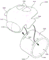
参考图26和图27,根据实施例的远程控制设备2000包括基座部分2002。基座部分2002包括用于接纳远程控制设备2000的内部部件的内部区域,内部部件包括无线通信系统2004,其包括无线发送器2006,用于从远程控制设备20发送无线命令,参见图26。Referring to FIGS. 26 and 27 , a remote control device 2000 according to an embodiment includes a base portion 2002 . The base portion 2002 includes an interior area for receiving internal components of the remote control device 2000, including a wireless communication system 2004 including a wireless transmitter 2006 for transmitting wireless commands from the remote control device 20, see FIG.

基座部分2002可以适当地成形以围绕穿戴远程控制设备2000的操作者的肢体的至少一部分装配。肢体可以是至少一个手指,例如,根据实施例是食指或食指和中指。如图26和图27中所示,基座部分2002可以包括第一区段2010和第二区段2012,第一区段2010被配置为定位在操作者肢体的顶部上方,第二区段2012连接到第一区段2010并被配置为定位在操作者肢体的一侧上方。第一和第二区段2010、2012可以被布置为使得在它们之间限定角度α,其中角度α优选地是锐角,使得第一和第二区段2010、2012有效地支撑操作者的肢体的一部分。Base portion 2002 may be suitably shaped to fit around at least a portion of the limb of an operator wearing remote control device 2000 . The limb may be at least one finger, for example, according to an embodiment, the index finger or the index and middle fingers. As shown in FIGS. 26 and 27 , the base portion 2002 can include a first section 2010 configured to be positioned over the top of the operator's limb and a second section 2012 . Connected to the first section 2010 and configured to be positioned over one side of the operator's limb. The first and second sections 2010, 2012 may be arranged such that an angle α is defined therebetween, wherein the angle α is preferably an acute angle, such that the first and second sections 2010, 2012 effectively support the limb of the operator. part.

远程控制设备2000还包括至少一个控件2020,诸如按钮、控制杆、开关等,如上所述。至少一个控件2020可以位于基座部分2002的外表面2022,即,当远程控制设备2000正被操作者穿戴时背对操作者的肢体的表面中。优选地,至少一个控件2020设置在基座部分2002的背对操作者食指的第二区段2012中,使得至少一个控件2020可以由操作者的拇指致动。至少一个控件2020可通信地耦合到无线通信系统2004,其中至少一个控件2020的致动使得无线发送器2006向与远程控制设备2000配对的车辆发送对应的无线命令。Remote control device 2000 also includes at least one control 2020, such as a button, lever, switch, etc., as described above. At least one control 2020 may be located in an outer surface 2022 of base portion 2002, ie, the surface facing away from the operator's limb when remote control device 2000 is being worn by the operator. Preferably, the at least one control 2020 is disposed in the second section 2012 of the base portion 2002 facing away from the operator's index finger such that the at least one control 2020 can be actuated by the operator's thumb. At least one control 2020 is communicatively coupled to wireless communication system 2004 , wherein actuation of at least one control 2020 causes wireless transmitter 2006 to transmit a corresponding wireless command to a vehicle paired with remote control device 2000 .

根据该实施例的远程控制设备2000还包括耦合到基座部分2002的固定结构2030(为了清楚起见,固定结构2030已从图27中移除)。固定结构2030可以包括保持带2032,保持带2032包括例如钩环带紧固件以将远程控制设备2000固定到操作者的肢体。保持带2032的至少一部分,例如,接触操作者的肢体的部分,可以包括抓握材料2033,诸如硅树脂,其提供附加的阻力以防止远程控制设备2000在操作者的肢体上滑动或旋转。基座部分2002可以设有位于第一和第二区段2010、2012中的每一个的远侧部分中的第一和第二槽2034和2036,用于接纳固定结构2030的相应部分。根据该实施例,第一槽2034接纳固定结构2030的紧固件部分2038以将固定结构2030紧固到基座部分2002,例如,经由缝合、胶合、嵌件模制或以其它方式将固定结构2030封装或固定到基座部分2002。固定结构2030的固定部分2040然后被馈送通过第二槽2036并折回,使得固定结构2030可以例如经由钩环带紧固件固定到其自身。要注意的是,固定结构2030可以采用保持带以外的其它形式,诸如刚性紧固件、柔性套筒等。The remote control device 2000 according to this embodiment also includes a fixing structure 2030 coupled to the base portion 2002 (the fixing structure 2030 has been removed from FIG. 27 for clarity). The securing structure 2030 may include a retention strap 2032 comprising, for example, hook and loop strap fasteners to secure the remote control device 2000 to the operator's limb. At least a portion of the retention strap 2032, eg, the portion that contacts the operator's limb, may include a gripping material 2033, such as silicone, that provides additional resistance to prevent the remote control device 2000 from sliding or rotating on the operator's limb. The base portion 2002 may be provided with first and second slots 2034 and 2036 in a distal portion of each of the first and second sections 2010 , 2012 for receiving respective portions of the fixation structure 2030 . According to this embodiment, first slot 2034 receives fastener portion 2038 of securing structure 2030 to secure securing structure 2030 to base portion 2002, for example, via stitching, gluing, insert molding, or otherwise securing the securing structure 2030 to base portion 2002. 2030 is encapsulated or secured to base portion 2002. The securing portion 2040 of the securing structure 2030 is then fed through the second slot 2036 and folded back so that the securing structure 2030 can be secured to itself, for example via a hook and loop fastener. It is to be noted that the securing structure 2030 may take other forms than retaining straps, such as rigid fasteners, flexible sleeves, and the like.

开口2042被限定在基座部分2002的内表面2044和固定结构2030的固定部分2040之间,用于接纳操作者的肢体,参见图26。开口2042的尺寸可以适当地接纳远程控制设备2000旨在被穿戴在其上的任何肢体。可以调整固定结构2030以适应不同尺寸的肢体或者使得远程控制设备2000可以穿戴在诸如手套(未示出)之类的衣服上。An opening 2042 is defined between an inner surface 2044 of the base portion 2002 and the fixation portion 2040 of the fixation structure 2030 for receiving an operator's limb, see FIG. 26 . Opening 2042 may be suitably sized to accommodate any limb on which remote control device 2000 is intended to be worn. The securing structure 2030 can be adjusted to accommodate different sized limbs or to allow the remote control device 2000 to be worn on clothing such as gloves (not shown).

远程控制设备2000还包括插入构件2050,插入构件2050可移除地附接到基座部分2002或固定结构2030中的至少一个,其中插入构件2050实现开口2042的尺寸的减小。根据这个实施例,插入构件2050包括接合基座部分2002的内表面2044的外表面2052。插入构件外表面2052和基座部分内表面2044可以对应地成形以彼此贴合,使得在插入构件2050和基座部分2002之间形成紧密配合。The remote control device 2000 also includes an insert member 2050 removably attached to at least one of the base portion 2002 or the fixed structure 2030 , wherein the insert member 2050 effects a reduction in the size of the opening 2042 . According to this embodiment, the insertion member 2050 includes an outer surface 2052 that engages the inner surface 2044 of the base portion 2002 . Insert member outer surface 2052 and base portion inner surface 2044 may be correspondingly shaped to fit each other such that a tight fit is formed between insert member 2050 and base portion 2002 .

在图26的实施例中,插入构件2050经由插入构件2050的一对接片2060可移除地附接到基座部分2002,插入构件2050的这对接片2060被基座部分2002的表面(诸如基座部分2002的外表面2022)接纳,或者接纳在基座部分2002中形成的用于接纳接片2060的槽(在该实施例中未示出)中。要注意的是,接片2060可以形成为基座部分2002的一部分,其中槽在插入构件2050中形成用于接纳接片2060。也可以使用附加的或更少的接片2060(和对应的槽,如果存在的话),并且插入构件2050可以使用其它紧固件可移除地附接到基座部分2002,其一些示例将在下面参考图28-图37进行讨论。In the embodiment of FIG. 26 , the insertion member 2050 is removably attached to the base portion 2002 via a pair of tabs 2060 of the insertion member 2050 that are secured by a surface of the base portion 2002 , such as a base. The outer surface 2022 of the seat portion 2002), or is received in a groove (not shown in this embodiment) formed in the base portion 2002 for receiving the tab 2060. It is noted that the tab 2060 may be formed as part of the base portion 2002 with a slot formed in the insert member 2050 for receiving the tab 2060 . Additional or fewer tabs 2060 (and corresponding slots, if present) may also be used, and the insert member 2050 may be removably attached to the base portion 2002 using other fasteners, some examples of which will be discussed in The following discussion is made with reference to Figures 28-37.

根据这个实施例,插入构件2050在其第一端部分2072处包括凹口2070(参见图27),以接纳固定结构2030的固定部分2040。According to this embodiment, the insertion member 2050 includes a notch 2070 at its first end portion 2072 (see FIG. 27 ) to receive the fixation portion 2040 of the fixation structure 2030 .

插入构件2050可以由具有与形成基座部分2002的材料不同的物理性质的材料形成。作为几个非限制性示例,插入构件2050可以具有不同于基座部分2002的物理性质的一种或多种以下物理性质:更高的摩擦系数,使得插入构件2050比基座部分2002具有更大的抓握力;更低的硬度,使得插入构件2050比基座部分2002更软;更高的压缩性,使得插入构件2050比基座部分2002更可压缩;和/或更高的透气性,使得与通过基座部分2002相比,更多的空气可以通过插入构件2050被引入到操作者的肢体。Insertion member 2050 may be formed from a material having different physical properties than the material forming base portion 2002 . As a few non-limiting examples, the insertion member 2050 may have one or more of the following physical properties different from those of the base portion 2002: a higher coefficient of friction such that the insertion member 2050 has a greater lower hardness, making the insertion member 2050 softer than the base portion 2002; higher compressibility, making the insertion member 2050 more compressible than the base portion 2002; and/or higher air permeability, making the More air may be introduced to the operator's extremity through the insertion member 2050 than through the base portion 2002 .

附加地或替代地,插入构件2050可以具有与基座部分2002不同的纹理以改变插入构件2050相对于基座部分2002的手感和/或抓握特性。例如,根据一些实施例,插入构件2050可以包括多个表面特征2080,其从插入构件2050的内表面2082向外或向内中的至少一个延伸。示例表面特征2080包括肋、穿孔、凹坑、突起、脊、通道和/或提供具有增加抓握力的区域的粗糙区域。表面特征2080还可以增加透气性/气流、允许排汗、增加舒适度等。参考图27,根据该实施例的插入构件2050的表面特征2080包括从插入构件2050的第一端部分2072从插入构件内表面2082向外延伸到与基座部分2002的第一区段2010相邻的插入构件2050的第二端部分2086的多个肋。根据该实施例的肋实现增加由插入构件2050提供的抓握,以防止远程控制设备2000在操作者的肢体上滑动。肋还增加了通过相邻肋之间限定的通道的气流。应该注意的是,肋可以根据需要在其它方向延伸,诸如垂直于图27中所示的方向。肋也可以在多于一个方向上延伸,诸如例如以交叉图案延伸。Additionally or alternatively, the insertion member 2050 may have a different texture than the base portion 2002 to alter the feel and/or grip characteristics of the insertion member 2050 relative to the base portion 2002 . For example, according to some embodiments, insertion member 2050 may include a plurality of surface features 2080 extending at least one of outwardly or inwardly from inner surface 2082 of insertion member 2050 . Example surface features 2080 include ribs, perforations, dimples, protrusions, ridges, channels, and/or roughened areas that provide areas with increased grip. Surface features 2080 may also increase breathability/airflow, allow perspiration to wick away, increase comfort, and the like. Referring to FIG. 27 , the surface features 2080 of the insertion member 2050 according to this embodiment include extending outwardly from the insertion member inner surface 2082 from the first end portion 2072 of the insertion member 2050 to adjacent the first section 2010 of the base portion 2002 . A plurality of ribs on the second end portion 2086 of the insertion member 2050. The ribs according to this embodiment enable to increase the grip provided by the insertion member 2050 to prevent the remote control device 2000 from slipping on the operator's limb. The ribs also increase airflow through the channels defined between adjacent ribs. It should be noted that the ribs may extend in other directions as desired, such as perpendicular to the direction shown in FIG. 27 . The ribs may also extend in more than one direction, such as for example in a cross pattern.

现在参考图28,根据另一个实施例的插入构件2050被延伸,使得它不仅沿着基座部分2002的第二区段2012的大部分和基座部分2002的第一区段2010的一部分延伸(与图26和图27的插入构件2050一样),而且图28的插入构件2050沿着基座部分2002的第一区段2010和第二区段2012两者的大部分延伸。因此,与图26和图27的远程控制设备2000的插入构件2050相比,根据该实施例的插入构件2050围绕操作者的肢体(例如,食指)的更大部分延伸。由于该实施例的插入构件2050沿着基座部分2002的第一区段2010的大部分延伸,因此插入构件2050包括用于接纳固定结构2030的槽2051,为了清楚起见,该固定结构2030已从图28中移除。Referring now to FIG. 28 , an insertion member 2050 according to another embodiment is extended such that it not only extends along most of the second section 2012 of the base portion 2002 and a portion of the first section 2010 of the base portion 2002 ( 26 and 27), and the insertion member 2050 of FIG. 28 extends along most of both the first section 2010 and the second section 2012 of the base portion 2002. Thus, the insertion member 2050 according to this embodiment extends around a larger portion of the operator's limb (eg index finger) than the insertion member 2050 of the remote control device 2000 of FIGS. 26 and 27 . Since the insertion member 2050 of this embodiment extends along most of the first section 2010 of the base portion 2002, the insertion member 2050 includes a slot 2051 for receiving a fixation structure 2030, which has been removed from Removed in Figure 28.

此外,代替肋,根据该实施例的插入构件表面特征2080包括从插入构件内表面2082向外延伸的突起。表面特征2080可以附加地或替代地包括从插入构件内表面2082向内延伸的凹坑。根据该实施例的突起实现增加由插入构件2050提供的抓握,以防止远程控制设备2000在操作者的肢体上滑动。Furthermore, instead of ribs, the insertion member surface feature 2080 according to this embodiment includes protrusions extending outwardly from the insertion member inner surface 2082 . Surface features 2080 may additionally or alternatively include dimples extending inwardly from insertion member inner surface 2082 . The protrusions according to this embodiment enable to increase the grip provided by the insertion member 2050 to prevent the remote control device 2000 from slipping on the operator's limb.

图28中所示的远程控制设备2000的其余结构可以与图26和图27的远程控制设备2000的结构相同或相似。The rest of the structure of the remote control device 2000 shown in FIG. 28 may be the same as or similar to that of the remote control device 2000 of FIGS. 26 and 27 .

现在转向图29,与图28的插入构件2050类似,根据该实施例的插入构件2050被延伸,使得它沿着基座部分2002的第一区段2010和第二区段2012两者的大部分延伸。因此,与图26和图27的远程控制设备2000的插入构件2050相比,根据该实施例的插入构件2050围绕操作者的肢体(例如,食指)的更大部分延伸。该实施例的插入构件2050的相对的第一和第二端部分2072、2086可以向内弯曲以更牢固地支撑操作者的肢体。虽然未在该实施例中具体示出,但是图29的插入构件2050可以包括如本文所公开的一个或多个表面特征2080。Turning now to FIG. 29 , similar to the insertion member 2050 of FIG. 28 , the insertion member 2050 according to this embodiment is extended such that it extends along most extend. Thus, the insertion member 2050 according to this embodiment extends around a larger portion of the operator's limb (eg index finger) than the insertion member 2050 of the remote control device 2000 of FIGS. 26 and 27 . The opposing first and second end portions 2072, 2086 of the insertion member 2050 of this embodiment can be bent inwardly to more securely support the operator's limb. Although not specifically shown in this embodiment, the insertion member 2050 of FIG. 29 may include one or more surface features 2080 as disclosed herein.

图29中所示的远程控制设备2000的其余结构可以与图26和图27的远程控制设备2000的结构相同或相似。The rest of the structure of the remote control device 2000 shown in FIG. 29 may be the same as or similar to that of the remote control device 2000 of FIGS. 26 and 27 .

在图30中所示的又一个实施例中,插入构件2050的表面特征2080可以包括一系列交替的脊和通道,它们分别从插入构件2050的内表面2082向外和向内延伸。脊和通道实现增加由插入构件2050提供的抓握,以防止远程控制设备2000在操作者的肢体上滑动,并且还增加通过相邻脊之间限定的通道的气流。In yet another embodiment shown in FIG. 30 , the surface features 2080 of the insertion member 2050 can include a series of alternating ridges and channels extending outwardly and inwardly from the inner surface 2082 of the insertion member 2050 , respectively. The ridges and channels enable to increase the grip provided by the insertion member 2050 to prevent the remote control device 2000 from slipping on the operator's limb, and also to increase the airflow through the channels defined between adjacent ridges.

图30中所示的远程控制设备2000的其余结构可以与图29的远程控制设备2000的结构相同或相似。The rest of the structure of the remote control device 2000 shown in FIG. 30 may be the same as or similar to that of the remote control device 2000 of FIG. 29 .

在图26-图30的实施例中,各种插入构件2050可以从相应的基座部分2002和/或固定结构2030移除,其中根据这些实施例,远程控制设备2000可以在没有插入构件2050的情况下使用。替代地,插入构件2050可以由可以选自多个插入构件的另一个插入构件代替。这些多个插入构件中的每一个可以具有与其它插入构件不同的尺寸、形状、纹理、硬度、透气性、压缩性或摩擦系数中的至少一个。因此,远程控制设备2000可以根据将要使用它的操作者的喜好和/或满足将远程控制设备2000固定到操作者的肢体所需的维度来定制。In the embodiments of FIGS. 26-30 , the various insertion members 2050 can be removed from the corresponding base portion 2002 and/or fixed structure 2030 , wherein according to these embodiments, the remote control device 2000 can be removed without the insertion members 2050 . case use. Alternatively, the insertion member 2050 may be replaced by another insertion member which may be selected from a plurality of insertion members. Each of the plurality of insertion members may have at least one of a different size, shape, texture, stiffness, air permeability, compressibility, or coefficient of friction than the other insertion members. Thus, the remote control device 2000 may be customized according to the preferences of the operator who will use it and/or to meet the dimensions required to secure the remote control device 2000 to the operator's extremity.

现在转向图31,根据实施例的远程控制设备2100包括基座部分2102。基座部分2102包括用于接纳远程控制设备2100的内部部件的内部区域,包括无线通信系统2104,该无线通信系统2104包括无线发送器2106,用于从远程控制设备2100发送无线命令。Turning now to FIG. 31 , a remote control device 2100 includes a base portion 2102 in accordance with an embodiment. Base portion 2102 includes an interior area for receiving internal components of remote control device 2100 , including wireless communication system 2104 including wireless transmitter 2106 for transmitting wireless commands from remote control device 2100 .

基座部分2102可以适当地成形以围绕穿戴远程控制设备2100的操作者的肢体的至少一部分装配。肢体可以是至少一个手指,例如,根据实施例是食指或食指和中指。如图31中所示,基座部分2102可以包括第一区段2110和第二区段2112,第一区段2110被配置为定位在操作者肢体的顶部上方,第二区段2112连接到第一区段2110并被配置为定位在操作者肢体的一侧上方。第一和第二区段2110、2112可以被布置为使得在它们之间限定角度α,其中角度α优选地是锐角,使得第一和第二区段2110、2112有效地支撑操作者的肢体的一部分。Base portion 2102 may be suitably shaped to fit around at least a portion of the limb of an operator wearing remote control device 2100 . The limb may be at least one finger, for example, according to an embodiment, the index finger or the index and middle fingers. As shown in FIG. 31 , the base portion 2102 can include a first section 2110 configured to be positioned over the top of the operator's limb and a second section 2112 connected to the second section 2112. A section 2110 is also configured to be positioned over one side of the operator's limb. The first and second sections 2110, 2112 may be arranged such that an angle α is defined therebetween, wherein the angle α is preferably an acute angle, such that the first and second sections 2110, 2112 effectively support the limb of the operator. part.

远程控制设备2100还包括至少一个控件2120,诸如按钮、控制杆、开关等,如上所述。至少一个控件2120可以位于基座部分2102的外表面2122,即,当远程控制设备2100正被操作者穿戴时背对操作者的肢体的表面中。优选地,至少一个控件2120设置在基座部分2102的背对操作者食指的第二区段2112中,使得至少一个控件2120可以由操作者的拇指致动。至少一个控件2120可通信地耦合到无线通信系统2104,其中至少一个控件2120的致动使得无线发送器2106向与远程控制设备2000配对的物料搬运车辆发送对应的无线命令。The remote control device 2100 also includes at least one control 2120, such as a button, lever, switch, etc., as described above. At least one control 2120 may be located in an outer surface 2122 of base portion 2102, ie, the surface facing away from the operator's limb when remote control device 2100 is being worn by the operator. Preferably, the at least one control 2120 is disposed in the second section 2112 of the base portion 2102 facing away from the operator's index finger such that the at least one control 2120 can be actuated by the operator's thumb. At least one control 2120 is communicatively coupled to wireless communication system 2104 , wherein actuation of at least one control 2120 causes wireless transmitter 2106 to transmit a corresponding wireless command to a materials handling vehicle paired with remote control device 2000 .

远程控制设备2100还包括可移除地附接到基座部分2102的插入构件2150(也参见图32)。开口2142由插入构件2150限定,用于接纳操作者的肢体,参见图31和图32。开口2142的尺寸可以被确定为适当地接纳远程控制设备2100打算穿戴在其上的任何肢体,例如操作者的食指和中指。插入构件2150可以如将在下面更详细地描述的那样被调整以适应不同尺寸的肢体和/或使得远程控制设备2100可以穿戴在诸如手套(未示出)之类的衣服上。The remote control device 2100 also includes an insert member 2150 removably attached to the base portion 2102 (see also FIG. 32 ). An opening 2142 is defined by the insertion member 2150 for receiving an operator's limb, see FIGS. 31 and 32 . Opening 2142 may be sized to appropriately receive any limb on which remote control device 2100 is intended to be worn, such as the operator's index and middle fingers. Insertion member 2150 may be adjusted as will be described in more detail below to accommodate different sized limbs and/or to allow remote control device 2100 to be worn on clothing such as gloves (not shown).

根据该实施例,插入构件2150包括接合基座部分2102的内表面2144的外表面2152,参见图31。插入构件外表面2152和基座部分内表面2144可以对应地成形以彼此贴合,使得在插入构件2150和基座部分2102之间产生紧密配合。According to this embodiment, the insertion member 2150 includes an outer surface 2152 that engages the inner surface 2144 of the base portion 2102, see FIG. 31 . Insert member outer surface 2152 and base portion inner surface 2144 may be correspondingly shaped to fit each other such that a snug fit is created between insert member 2150 and base portion 2102 .

在图31和图32的实施例中,插入构件2150经由插入构件2150的一对相对的接片2160可移除地附接到基座部分2102,插入构件2150的这对相对接片2160被接纳在形成于基座部分2102中的对应槽2162中,但是要注意的是,接片2160可以形成为基座部分2102的一部分,其中槽在插入构件2150中形成,例如,如图33的实施例中所示,这将在下面讨论。也可以在不使用槽2162的情况下,由基座部分2002的外表面2122接纳接片2160。也可以使用附加的或更少的接片2160(和对应的槽,如果存在的话),并且插入构件2150可以使用其它紧固件可移除地附接到基座部分2102。插入构件2150的替代配置如图32A-图32D中所示,其包括用于支撑接片2160的附加示例性结构。In the embodiment of FIGS. 31 and 32 , the insertion member 2150 is removably attached to the base portion 2102 via a pair of opposing tabs 2160 of the insertion member 2150 which are received In a corresponding slot 2162 formed in the base portion 2102, however, it is noted that the tab 2160 may be formed as part of the base portion 2102 with the slot formed in the insert member 2150, for example, as in the embodiment of FIG. , which will be discussed below. The tabs 2160 may also be received by the outer surface 2122 of the base portion 2002 without the use of the slots 2162 . Additional or fewer tabs 2160 (and corresponding slots, if present) may also be used, and the insertion member 2150 may be removably attached to the base portion 2102 using other fasteners. An alternate configuration of insert member 2150 is shown in FIGS. 32A-32D , which includes additional exemplary structures for supporting tabs 2160 .

插入构件2150可以由具有与形成基座部分2102的材料不同的物理性质的材料形成。作为几个非限制性示例,插入构件2150具有不同于基座部分2102的物理性质的一种或多种以下物理性质:更高的摩擦系数,使得插入构件2150比基座部分2102具有更大的抓握力;更低的硬度,使得插入构件2150比基座部分2102更软;更高的压缩性,使得插入构件2150比基座部分2102更可压缩;和/或更高的透气性,使得与通过基座部分2102相比,更多的空气可以通过插入构件2150被引入到操作者的肢体。Insertion member 2150 may be formed from a material having different physical properties than the material forming base portion 2102 . As a few non-limiting examples, the insertion member 2150 has one or more of the following physical properties different from those of the base portion 2102: a higher coefficient of friction such that the insertion member 2150 has a greater friction than the base portion 2102 grip; lower stiffness, making the insertion member 2150 softer than the base portion 2102; higher compressibility, making the insertion member 2150 more compressible than the base portion 2102; and/or higher air permeability, making it more compatible with More air may be introduced to the operator's extremity through the insertion member 2150 than through the base portion 2102 .

附加地或替代地,插入构件2150可以具有与基座部分2102不同的纹理以改变插入构件2150相对于基座部分2102的手感和/或抓握特性。例如,根据一些实施例,插入构件2150可以包括多个表面特征2180,其从插入构件2150的内表面2182向外或向内中的至少一个延伸。示例性表面特征2180包括肋、穿孔、凹坑、突起、脊、通道和/或提供具有增加抓握力的区域的粗糙区域。表面特征2180还可以增加透气性/气流、允许排汗、增加舒适度等。参考图32,根据该实施例的插入构件2150的表面特征2180包括粗糙区域。粗糙区域可以位于插入构件内表面2182中的任何地方,并且可以包括一个以上的粗糙区域。在图31和图32中所示的实施例中,粗糙区域位于与插入构件2150可移除地附接到基座部分2102的位置相对的位置。根据该实施例的粗糙区域实现增加由插入构件2150提供的抓握,以防止远程控制设备2100在操作者的肢体上滑动。根据另一个实施例,图32中被设计为粗糙区域的区域可以是插入构件2150的柔性区域,其允许插入构件2150扩展以适应不同尺寸的肢体和/或使得远程控制设备2100可以被穿戴在衣服上。Additionally or alternatively, the insertion member 2150 may have a different texture than the base portion 2102 to alter the feel and/or grip characteristics of the insertion member 2150 relative to the base portion 2102 . For example, according to some embodiments, insertion member 2150 may include a plurality of surface features 2180 that extend at least one of outwardly or inwardly from inner surface 2182 of insertion member 2150 . Exemplary surface features 2180 include ribs, perforations, dimples, protrusions, ridges, channels, and/or roughened areas that provide areas with increased grip. Surface features 2180 may also increase breathability/airflow, allow perspiration to wick away, increase comfort, and the like. Referring to FIG. 32, the surface features 2180 of the insertion member 2150 according to this embodiment include roughened areas. The roughened region may be located anywhere in the insertion member inner surface 2182 and may include more than one roughened region. In the embodiment shown in FIGS. 31 and 32 , the roughened area is located opposite where the insertion member 2150 is removably attached to the base portion 2102 . The roughened area according to this embodiment enables to increase the grip provided by the insert member 2150 to prevent the remote control device 2100 from slipping on the operator's limb. According to another embodiment, the area designed as a rough area in FIG. 32 may be a flexible area of the insertion member 2150, which allows the insertion member 2150 to expand to accommodate limbs of different sizes and/or allows the remote control device 2100 to be worn under clothing. superior.

插入构件2150可以由可膨胀材料形成,例如弹性体或合成纤维,使得它可以被拉伸以增加开口2142的尺寸。图31中所示的实线插入构件2150图示了处于松弛或默认状态的插入构件2150,而图31中所示的点划线插入构件2150'图示了处于拉伸或展开状态的插入构件2150。在图31和图32所示的实施例中,插入构件2150包括封闭的、可扩展的/柔性的圆柱形构件,其适于接纳呈食指和中指形式的操作者肢体。插入构件2150的可扩展性允许插入构件2150被拉伸以适合较大的手指和/或操作者穿戴的手套。Insertion member 2150 may be formed from an expandable material, such as an elastomer or synthetic fiber, such that it can be stretched to increase the size of opening 2142 . The insertion member 2150 shown in solid line in FIG. 31 illustrates the insertion member 2150 in a relaxed or default state, while the insertion member 2150' shown in dashed lines in FIG. 31 illustrates the insertion member in a stretched or expanded state. 2150. In the embodiment shown in Figures 31 and 32, the insertion member 2150 comprises a closed, expandable/flexible cylindrical member adapted to receive an operator's limb in the form of the index and middle fingers. The expandability of the insertion member 2150 allows the insertion member 2150 to be stretched to fit larger fingers and/or gloves worn by the operator.

图33描绘了类似于图31和图32的远程控制设备2100,并且具有限定开口2142的插入构件2150的另一个示例性远程控制设备2100。根据图33的插入构件2150由可膨胀材料形成,例如弹性体或合成纤维,使得它可以被拉伸以增加开口2142的尺寸。在图33所示的实施例中,插入构件2150包括限定开口2142并适于接纳呈单个手指(例如食指)形式的操作者肢体的封闭的、可扩展的/柔性的、圆柱形构件。插入构件2150的可扩展性允许插入构件2150被拉伸以适合较大手指和/或操作者穿戴的手套。如上文简要指出的,根据该实施例的接片2160形成为基座部分2102的一部分,并且接纳接片2160以将插入构件2150固定到基座部分2002的槽2162形成在插入构件2150中。虽然未在该实施例中具体示出,但是图33的插入构件2150可以包括如本文所公开的一个或多个表面特征2180。FIG. 33 depicts another exemplary remote control device 2100 similar to the remote control device 2100 of FIGS. 31 and 32 , and having an insertion member 2150 defining an opening 2142 . The insertion member 2150 according to FIG. 33 is formed from an expandable material, such as an elastomer or synthetic fibers, so that it can be stretched to increase the size of the opening 2142 . In the embodiment shown in FIG. 33, insertion member 2150 comprises a closed, expandable/flexible, cylindrical member defining opening 2142 and adapted to receive an operator's limb in the form of a single finger (eg, index finger). The expandability of the insertion member 2150 allows the insertion member 2150 to be stretched to fit larger fingers and/or gloves worn by the operator. As noted briefly above, the tab 2160 according to this embodiment is formed as part of the base portion 2102 and the slot 2162 that receives the tab 2160 to secure the insert member 2150 to the base portion 2002 is formed in the insert member 2150 . Although not specifically shown in this embodiment, the insertion member 2150 of FIG. 33 may include one or more surface features 2180 as disclosed herein.

图33中所示的远程控制设备2100的其余结构可以与图31和图32的远程控制设备2000的结构相同或相似。The rest of the structure of the remote control device 2100 shown in FIG. 33 may be the same as or similar to that of the remote control device 2000 of FIGS. 31 and 32 .

图34和图35描绘了与图31和图32的远程控制设备2100类似,并且具有限定开口2142的插入构件2150的两个更多的示例性远程控制设备2100。图34和图35的插入构件2150包括相应的紧固件2153用于将插入构件2150固定到操作者的肢体。紧固件可以是例如图34中所示的按扣、图35中所示的钩环带、嵌入式磁铁或其它类型的紧固件。根据图34和图35实施例的插入构件2150可以包括表面特征2180,其包括从插入构件内表面2182向外延伸的突起(图34A中所示)、向内延伸到插入构件内表面2182中的凹坑(图34B中所示)、延伸穿过插入构件2150的穿孔(图35中所示)和/或其它表面特征中的任何一个或多个。根据这些实施例的插入构件2150可以由柔软的、可扩展的/柔性的材料形成,诸如用于增加抓握和舒适度的硅。FIGS. 34 and 35 depict two more exemplary remote control devices 2100 similar to the remote control devices 2100 of FIGS. 31 and 32 , and having an insertion member 2150 defining an opening 2142 . The insertion member 2150 of FIGS. 34 and 35 includes corresponding fasteners 2153 for securing the insertion member 2150 to the operator's limb. The fasteners may be, for example, snap buttons as shown in FIG. 34, hook and loop straps as shown in FIG. 35, embedded magnets, or other types of fasteners. Insertion member 2150 according to the embodiment of FIGS. 34 and 35 may include surface features 2180 including protrusions (shown in FIG. 34A ) extending outward from insertion member inner surface 2182 , protrusions extending inward into insertion member inner surface 2182 . Any one or more of dimples (shown in FIG. 34B ), perforations extending through insertion member 2150 (shown in FIG. 35 ), and/or other surface features. Insertion member 2150 according to these embodiments may be formed from a soft, expandable/flexible material, such as silicon for increased grip and comfort.

根据图34的插入构件2150的一对接片2160被接纳在基座部分2102中形成的对应槽2162中,以将插入构件2150卡扣到基座部分2102。根据图35的基座部分2012的多个接片2160被接纳在插入构件2150中形成的对应槽2162中以将插入构件2150固定到基座部分2102。A pair of tabs 2160 of the insertion member 2150 according to FIG. 34 are received in corresponding slots 2162 formed in the base portion 2102 to snap the insertion member 2150 to the base portion 2102 . A plurality of tabs 2160 of the base portion 2012 according to FIG. 35 are received in corresponding slots 2162 formed in the insert member 2150 to secure the insert member 2150 to the base portion 2102 .

图34和图35中所示的远程控制设备2100的其余结构可以与图31和图32的远程控制设备2000的结构相同或相似。The rest of the structure of the remote control device 2100 shown in FIGS. 34 and 35 may be the same as or similar to that of the remote control device 2000 of FIGS. 31 and 32 .

图36描绘了与图35的远程控制设备2100类似,并且具有限定开口2142的插入构件2150的另一个示例性远程控制设备2100。根据图36的插入构件2150由比形成基座部分2102的材料更软的材料形成,例如棉/弹性纤维混合物、弹性体或合成纤维。在图36所示的实施例中,插入构件2150包括适于接纳操作者的食指形式的肢体的封闭的、可扩展的/柔性的圆柱形构件,其中插入构件2150是可扩展的,使得它可以被拉伸以增加开口2142的尺寸。插入构件2150的可扩展性允许它被拉伸以适合较大手指和/或操作者穿戴的手套,并且形成插入构件2150的较软材料可以增加舒适度。根据这个实施例的插入构件2150的接片2160可以滑入到在基座部分2102中形成的对应槽2162中。虽然未在该实施例中具体示出,但是图36的插入构件2150可以包括如本文公开的一个或多个表面特征2180。FIG. 36 depicts another exemplary remote control device 2100 similar to remote control device 2100 of FIG. 35 and having an insertion member 2150 defining an opening 2142 . The insertion member 2150 according to Fig. 36 is formed of a softer material than the material forming the base portion 2102, such as a cotton/elastane blend, elastomer or synthetic fibres. In the embodiment shown in FIG. 36, the insertion member 2150 comprises a closed, expandable/flexible cylindrical member adapted to receive a limb in the form of an operator's index finger, wherein the insertion member 2150 is expandable such that it can is stretched to increase the size of the opening 2142. The expandability of the insert member 2150 allows it to be stretched to fit larger fingers and/or gloves worn by the operator, and the softer material forming the insert member 2150 can increase comfort. The tabs 2160 of the insert member 2150 according to this embodiment can be slid into corresponding slots 2162 formed in the base portion 2102 . Although not specifically shown in this embodiment, the insertion member 2150 of FIG. 36 may include one or more surface features 2180 as disclosed herein.

图36中所示的远程控制设备2100的其余结构可以与图35的远程控制设备2000的结构相同或相似。The rest of the structure of the remote control device 2100 shown in FIG. 36 may be the same as or similar to that of the remote control device 2000 of FIG. 35 .

图37描绘了与图31和图32的远程控制设备2100类似,并且具有插入构件2150的另一个示例性远程控制设备2100。在图37所示的实施例中,插入构件2150与基座部分2102协作以限定开口2142。由基座部分2102和插入构件2150限定的开口2142适于接纳操作者的食指形式的肢体。FIG. 37 depicts another exemplary remote control device 2100 similar to the remote control device 2100 of FIGS. 31 and 32 , and having an insertion member 2150 . In the embodiment shown in FIG. 37 , insert member 2150 cooperates with base portion 2102 to define opening 2142 . An opening 2142 defined by base portion 2102 and insertion member 2150 is adapted to receive a limb in the form of an operator's index finger.

根据该实施例的插入构件2150可以是可扩展的/柔性的。插入构件2150的可扩展性允许插入构件2150被拉伸以适合较大手指和/或操作者穿戴的手套。Insertion member 2150 according to this embodiment may be expandable/flexible. The expandability of the insertion member 2150 allows the insertion member 2150 to be stretched to fit larger fingers and/or gloves worn by the operator.

根据该实施例的基座部分2102的一对接片2160配合在插入构件2150中形成的对应槽2162中,以将插入构件2150固定到基座部分2102。虽然未在该实施例中具体示出,但是图37的插入构件2150可以包括如本文公开的一个或多个表面特征2180。A pair of tabs 2160 of the base portion 2102 according to this embodiment fit into corresponding slots 2162 formed in the insert member 2150 to secure the insert member 2150 to the base portion 2102 . Although not specifically shown in this embodiment, the insertion member 2150 of FIG. 37 may include one or more surface features 2180 as disclosed herein.

图37中所示的远程控制设备2100的其余结构可以与图31和图32的远程控制设备2000的结构相同或相似。The rest of the structure of the remote control device 2100 shown in FIG. 37 may be the same as or similar to that of the remote control device 2000 of FIGS. 31 and 32 .

在图31-图37的实施例中,插入构件2150可以从基座部分2102移除并用可以选自多个插入构件的另一个插入构件替换。这些多个插入构件中的每一个可以具有与其它插入构件不同的尺寸、形状、纹理、硬度、透气性、压缩性或摩擦系数中的至少一个。因此,远程控制设备2100可以根据将要使用它的操作者的喜好和/或满足将远程控制设备2100固定到操作者的肢体所需的维度来定制。In the embodiment of FIGS. 31-37 , the insertion member 2150 can be removed from the base portion 2102 and replaced with another insertion member that can be selected from a plurality of insertion members. Each of the plurality of insertion members may have at least one of a different size, shape, texture, stiffness, air permeability, compressibility, or coefficient of friction than the other insertion members. Thus, the remote control device 2100 may be customized according to the preferences of the operator with whom it will be used and/or to meet the dimensions required to secure the remote control device 2100 to the operator's extremity.

现在转向图38A-图44,示出了根据实施例的附加远程控制设备。图38A-图44的每个远程控制设备可以包括与上述远程控制设备相同或相似的无线通信系统、可再充电电源、(一个或多个)控件、(一个或多个)充电触点和/或(一个或多个)传感器。在图38A-图44中使用相同的附图标记来描述相应远程控制设备的相似特征。Turning now to FIGS. 38A-44 , an additional remote control device is shown in accordance with an embodiment. Each of the remote control devices of FIGS. 38A-44 may include the same or similar wireless communication system, rechargeable power supply, control(s), charging contact(s) and/or or sensor(s). The same reference numerals are used in FIGS. 38A-44 to describe similar features of the corresponding remote control devices.

参考图38A-图38D,示出了根据实施例的示例性远程控制设备2000,其类似于图29和图30的远程控制设备2000并且包括附接到远程控制设备2000的基座部分2002的插入构件2092。在固定结构2030和插入构件2092之间限定用于接纳操作者的肢体的开口2041,参见图38D。插入构件2092可以由在形成阶段期间处于可延展状态的材料形成,使得它可以被形成定制形状并且最终以其定制形状硬化。为清楚起见,远程控制设备2000的固定结构2030已从图38A-38C中移除。Referring to FIGS. 38A-38D , an exemplary remote control device 2000 is shown, which is similar to the remote control device 2000 of FIGS. 29 and 30 and includes an insert attached to a base portion 2002 of the remote control device 2000 , according to an embodiment. Build 2092. An opening 2041 is defined between the fixation structure 2030 and the insertion member 2092 for receiving an operator's limb, see Fig. 38D. Insert member 2092 may be formed from a material that is in a malleable state during the forming phase so that it may be formed into a custom shape and eventually harden in its custom shape. The securing structure 2030 of the remote control device 2000 has been removed from FIGS. 38A-38C for clarity.

插入构件2092可以以不同方式形成定制形状。根据一个示例性实施例,要形成插入构件2092的材料可以是例如热塑性乙烯醋酸乙烯酯(EVA),并且被加热,诸如通过将材料放置在温/热液体浴中或加热源(诸如微波炉或烤箱)中,直到材料处于可延展状态。然后将加热的材料放置在操作者的肢体2090(例如,手指)上,以形成其定制形状,参见图38A和图38B。然后将材料从操作者的肢体2090中移除,参见图38B,并冷却以硬化成其定制形状。Insertion member 2092 can be formed into a custom shape in various ways. According to an exemplary embodiment, the material to form the insertion member 2092 may be, for example, thermoplastic ethylene vinyl acetate (EVA), and is heated, such as by placing the material in a bath of warm/hot liquid or a heat source such as a microwave oven or an oven. ) until the material is in a ductile state. The heated material is then placed on the operator's limb 2090 (eg, finger) to form its custom shape, see Figures 38A and 38B. The material is then removed from the operator's limb 2090, see Fig. 38B, and cooled to harden into its custom shape.

根据另一个示例性实施例,插入构件2092可以通过将两种或更多种材料混合在一起而形成,诸如,例如,使用聚二甲基硅氧烷(PMDS)的基础糊剂和具有硅酸烷基酯和辛酸亚锡的加速糊剂的两部分缩合硅,以产生临时可延展的材料。材料可以在可延展状态下压靠在操作者的肢体2090上,以将材料模塑成其定制形状,参见图38A和图38B。该材料然后可以例如利用化学反应经历硬化过程,以将插入构件2092硬化成其定制形状。According to another exemplary embodiment, the insertion member 2092 may be formed by mixing two or more materials together, such as, for example, using a base paste of polydimethylsiloxane (PMDS) and a base paste with silicic acid. Two-part condensation of alkyl esters and stannous octoate accelerated pastes to silicon to produce temporarily malleable materials. The material may be pressed against the operator's limb 2090 in an extensible state to mold the material into its custom shape, see Figures 38A and 38B. The material may then undergo a hardening process, such as using a chemical reaction, to harden the insert member 2092 into its custom shape.

在又一个示例性实施例中,插入构件2092可以由风干材料形成,诸如例如风干粘土,该材料在硬化之前在有限时间段内处于可延展状态。可以将材料保持防止暴露于空气,例如在真空中,直到它准备好形成其定制形状。一旦暴露于空气并且处于可延展状态时,材料就可以被压靠在操作者的肢体2090上以将材料模塑成其定制形状,参见图38A和图38B。这种材料在暴露于空气中时会随着时间的推移硬化成其定制形状。In yet another exemplary embodiment, the insert member 2092 may be formed from an air-dried material, such as, for example, air-dried clay, that is malleable for a limited period of time before hardening. The material can be kept from exposure to air, such as in a vacuum, until it is ready to be formed into its custom shape. Once exposed to air and in a malleable state, the material can be pressed against the operator's limb 2090 to mold the material into its custom shape, see Figures 38A and 38B. The material hardens into its custom shape over time when exposed to air.

现在参考图39-图39C,图示了根据实施例的另一个示例性远程控制设备2000。图39-图39C的远程控制设备2000包括固定结构2030(参见图39A-39C),其可以类似于图29和图30的远程控制设备2000的固定结构2030,并且还包括可以使用诸如一对紧固件2096(例如,螺钉)的紧固硬件保持在适当位置的可移除的可调整插入构件2094。如图39中所示,紧固件2096穿过插入构件2094中的开口2096A并被接纳在远程控制设备基座部分2002的对应插座2096B中。Referring now to FIGS. 39-39C , another exemplary remote control device 2000 is illustrated, in accordance with an embodiment. The remote control device 2000 of FIGS. 39-39C includes a fixed structure 2030 (see FIGS. 39A-39C ), which may be similar to the fixed structure 2030 of the remote control device 2000 of FIGS. Fastening hardware of fasteners 2096 (eg, screws) holds the removable adjustable insertion member 2094 in place. As shown in FIG. 39 , fasteners 2096 pass through openings 2096A in insertion member 2094 and are received in corresponding receptacles 2096B of remote control base portion 2002 .

插入构件2094可枢转地附接到基座部分2002,使得插入构件2094的位置可以被调整(或者插入构件2094可以被移除,如图39A中所示)以供具有不同尺寸手指的操作者和/或戴手套的操作者使用。例如,远程控制设备2000可以在如图39A中所示没有插入构件2094的情况下例如由具有较大尺寸手指2090的操作者和/或由戴手套的操作者使用,其中开口2041被限定在固定结构2030和远程控制设备基座部分2002之间,在这种配置中没有安装插入构件2094。插入构件2094可以通过移除紧固件2096然后从远程控制设备基座部分2002撤回插入构件2094而从远程控制设备基座部分2002移除。图39B示出了远程控制设备2000,其中插入构件2094安装在第一插入构件位置并用紧固件2096固定,以由具有中等尺寸手指2090的操作者穿戴。图39C示出了远程控制设备2000,其中插入构件2094安装在第二插入构件位置并用紧固件2096固定,以由具有较小尺寸手指2090的操作者穿戴。插入构件2094可以枢转,以便通过松开紧固件2096、将插入构件2094枢转至期望位置,以及然后重新拧紧紧固件2096来调整开口2041的尺寸。插入构件2094可以根据期望固定在任何数量的位置或者被移除(如图39A中所示)。Insertion member 2094 is pivotally attached to base portion 2002 such that the position of insertion member 2094 can be adjusted (or insertion member 2094 can be removed, as shown in FIG. 39A ) for operators with fingers of different sizes. and/or operators wearing gloves. For example, the remote control device 2000 may be used without the insertion member 2094 as shown in FIG. Between structure 2030 and remote control device base portion 2002, no insert member 2094 is installed in this configuration. Insertion member 2094 may be removed from remote control device base portion 2002 by removing fastener 2096 and then withdrawing insertion member 2094 from remote control device base portion 2002 . FIG. 39B shows remote control device 2000 with insertion member 2094 mounted in a first insertion member position and secured with fasteners 2096 for wear by an operator with medium sized fingers 2090 . FIG. 39C shows remote control device 2000 with insertion member 2094 mounted in a second insertion member position and secured with fasteners 2096 to be worn by an operator with fingers 2090 of smaller size. Insertion member 2094 may pivot to adjust the size of opening 2041 by loosening fastener 2096 , pivoting insertion member 2094 to a desired position, and then re-tightening fastener 2096 . Insertion member 2094 may be secured in any number of positions or removed (as shown in FIG. 39A ) as desired.

图40-图40C描绘了根据实施例的另一个示例性远程控制设备2000,该远程控制设备2000类似于图39-图39C的远程控制设备2000。40-40C depict another exemplary remote control device 2000 that is similar to the remote control device 2000 of FIGS. 39-39C , according to an embodiment.

根据这个实施例,远程控制设备2000的可移除插入构件2098包括细长开口2099以接纳固定结构2030的固定部分2040。根据这个实施例的插入构件2098在铰接紧固件2096上枢转(参见图40),铰接紧固件2096接纳在远程控制设备基座部分2002的对应插口2096B中(参见图40和40A)。插入构件2098可以在被操作者穿戴并使用固定结构2030紧固到他们的手指2090时自动调整/枢转至合适的尺寸。因此,根据该实施例,不需要松开/拧紧插入构件2098的紧固件2096来调整插入构件2098的位置,例如,从图40B中所示的用于具有中等尺寸手指2090的操作者的配置到图40C中所示的用于具有较小尺寸手指2090的操作者的配置。根据该实施例的插入构件2098如图40A中所示可以从远程控制设备基座部分2002移除,其中开口2041限定在固定结构2030和远程控制设备基座部分2002之间。在图40B和图40C中,开口2041被限定在固定结构2030和插入构件2098之间。According to this embodiment, the removable insert member 2098 of the remote control device 2000 includes an elongated opening 2099 to receive the fixing portion 2040 of the fixing structure 2030 . Insertion member 2098 according to this embodiment pivots on hinge fastener 2096 (see FIG. 40 ), which is received in a corresponding socket 2096B of remote control device base portion 2002 (see FIGS. 40 and 40A ). The insertion member 2098 may automatically adjust/pivot to the proper size when worn by the operator and secured to their finger 2090 using the securing structure 2030 . Thus, according to this embodiment, there is no need to loosen/tighten the fasteners 2096 of the insertion member 2098 to adjust the position of the insertion member 2098, for example, from the configuration shown in FIG. 40B for an operator with a medium-sized finger 2090 To the configuration shown in Fig. 40C for an operator with a smaller sized finger 2090. Insertion member 2098 according to this embodiment is removable from remote control base portion 2002 as shown in FIG. 40A , with opening 2041 defined between securing structure 2030 and remote control base portion 2002 . In FIGS. 40B and 40C , opening 2041 is defined between fixation structure 2030 and insertion member 2098 .

图41-图41D描绘了根据实施例的另一个示例性远程控制设备2000。图41-图41D的远程控制设备2000包括可移除的插入构件3000,该插入构件3000包括多个插入构件槽3002、3004、3006、3008。这些插入构件槽3002、3004、3006、3008允许如将在下面详细讨论的不同配置的固定结构2030。插入构件3000可以例如通过使固定结构2030馈送穿过插入构件槽3002、3004、3006、3008中的两个或更多个、通过使用适当的咬合结构将插入构件3000咬合到位、或者通过在插入构件3000和远程控制设备基座部分2002之间施加粘合材料可移除地固定到远程控制设备基座部分2002。插入构件3000可以由防滑型材料形成,诸如硅树脂,以防止远程控制设备2000在操作者的(一个或多个)手指上滑动或旋转。41-41D depict another exemplary remote control device 2000 according to an embodiment. The remote control device 2000 of FIGS. 41-41D includes a removable insertion member 3000 that includes a plurality of insertion member slots 3002 , 3004 , 3006 , 3008 . These insert member slots 3002, 3004, 3006, 3008 allow for different configurations of the securing structure 2030 as will be discussed in detail below. The insertion member 3000 can be inserted, for example, by feeding the securing structure 2030 through two or more of the insertion member slots 3002, 3004, 3006, 3008, by snapping the insertion member 3000 into place using a suitable snapping structure, or by Adhesive material is applied between 3000 and remote control device base portion 2002 to be removably secured to remote control device base portion 2002 . Insertion member 3000 may be formed of a non-slip type material, such as silicone, to prevent remote control device 2000 from sliding or rotating on the operator's finger(s).

如图41A中所示,在根据该实施例的第一配置中,远程控制设备2000可以在没有插入构件3000的情况下使用,其中在该第一配置中远程控制设备2000在远程控制设备基座部分2002和固定结构2030之间直接固定到操作者的食指2090,而没有插入构件3000。在第一配置中,开口2041限定在固定结构2030和远程控制设备基座部分2002之间。形成在远程控制设备基座部分2002中的第一槽2034接纳固定结构2030的紧固件部分2038以将固定结构2030紧固到基座部分2002,例如,经由缝合、胶合、嵌件模制,或以其它方式将固定结构2030封装或固定到基座部分2002。固定结构2030的固定部分2040被馈送穿过在远程控制设备基座部分2002中形成的第二槽2036并折回,使得固定结构2030可以例如经由钩环带紧固件固定到自身。As shown in FIG. 41A, in a first configuration according to this embodiment, the remote control device 2000 can be used without the insertion member 3000, wherein in the first configuration the remote control device 2000 is mounted on the remote control device base The part 2002 and the fixation structure 2030 are fixed directly to the operator's index finger 2090 without the insertion member 3000 . In the first configuration, an opening 2041 is defined between the fixed structure 2030 and the remote control base portion 2002 . A first slot 2034 formed in the remote control device base portion 2002 receives a fastener portion 2038 of the securing structure 2030 to secure the securing structure 2030 to the base portion 2002, for example, via stitching, gluing, insert molding, Or otherwise encapsulate or secure the securing structure 2030 to the base portion 2002 . The securing portion 2040 of the securing structure 2030 is fed through the second slot 2036 formed in the remote control base portion 2002 and folded back so that the securing structure 2030 can be secured to itself, eg via hook and loop fasteners.

图41B描绘了在根据该实施例的第二配置中的远程控制设备2000,其中插入构件3000固定到远程控制设备基座部分2002并且由操作者穿戴。在第二配置中,开口2041限定在固定结构2030和插入构件3000之间,其中固定结构2030的紧固件部分2038接纳在远程控制设备基座部分2002的第一槽2034中,然后固定结构2030穿透第二插入构件槽3004。固定结构2030的固定部分2040馈送穿过在远程控制设备基座部分2002中形成的第一插入构件槽3002和第二槽2036并折回,使得固定结构2030可以固定到自身。在第二配置中,远程控制设备2000在插入构件3000和固定结构2030之间固定到操作者的食指2090。操作者的中指2091可以靠在固定结构2030和插入构件3000上,以防止远程控制设备2000在操作者的食指2090上旋转。Figure 41B depicts the remote control device 2000 in a second configuration according to this embodiment, wherein the insert member 3000 is secured to the remote control device base portion 2002 and is worn by the operator. In a second configuration, an opening 2041 is defined between the securing structure 2030 and the insert member 3000, wherein the fastener portion 2038 of the securing structure 2030 is received in the first slot 2034 of the remote control base portion 2002, and then the securing structure 2030 The second insert member slot 3004 is penetrated. The securing portion 2040 of the securing structure 2030 is fed through the first insert member slot 3002 and the second slot 2036 formed in the remote control base portion 2002 and folded back so that the securing structure 2030 can be secured to itself. In the second configuration, the remote control device 2000 is secured to the operator's index finger 2090 between the insertion member 3000 and the securing structure 2030 . The operator's middle finger 2091 may rest on the fixation structure 2030 and the insertion member 3000 to prevent the remote control device 2000 from rotating on the operator's index finger 2090 .

图41C描绘了根据该实施例的第三配置中的远程控制设备2000,其中插入构件3000固定到远程控制设备基座部分2002并且由操作者穿戴。在第三配置中,开口2041限定在固定结构2030和插入构件3000之间,其中固定结构2030的紧固件部分2038接纳在第四插入构件槽3008中以将固定结构2030固定到插入构件3000,例如,经由缝合、胶合、嵌件模制,或以其它方式将固定结构2030封装或固定到插入构件3000。固定结构2030的固定部分2040馈送穿过在远程控制设备基座部分2002中形成的第一插入构件槽3002和第二槽2036并折回,使得固定结构2030可以固定到其自身。在第三配置中,远程控制设备2000在插入构件3000和固定结构2030之间固定到操作者的食指和中指2090、2091。操作者的无名指(未示出)可以靠在固定结构2030上,以防止远程控制设备2000在操作者的食指和中指2090、2091上旋转。Figure 41C depicts the remote control device 2000 in a third configuration according to this embodiment, wherein the insert member 3000 is secured to the remote control device base portion 2002 and is worn by the operator. In a third configuration, an opening 2041 is defined between the fixation structure 2030 and the insertion member 3000, wherein the fastener portion 2038 of the fixation structure 2030 is received in the fourth insertion member slot 3008 to secure the fixation structure 2030 to the insertion member 3000, For example, fixation structure 2030 is encapsulated or secured to insertion member 3000 via stitching, gluing, insert molding, or otherwise. The securing portion 2040 of the securing structure 2030 is fed through the first insert member slot 3002 and the second slot 2036 formed in the remote control base portion 2002 and folded back so that the securing structure 2030 can be secured to itself. In a third configuration, the remote control device 2000 is secured to the index and middle fingers 2090 , 2091 of the operator between the insertion member 3000 and the securing structure 2030 . The operator's ring finger (not shown) may rest on the fixed structure 2030 to prevent the remote control device 2000 from rotating on the operator's index and middle fingers 2090,2091.

图41D描绘了根据该实施例的第四配置中的由操作者穿戴的插入构件3000。第四配置类似于第三配置,但还包括馈送穿过第二和第三插入构件槽3004、3006的固定结构2030,其中插入构件3000在插入构件3000和固定结构2030之间固定到操作者的食指和中指2090、2091。根据第四配置,固定结构2030的一部分将操作者的食指和中指2090、2091分开,即,根据第四配置,两个分开的开口2042、2043限定在固定结构2030和插入构件3000之间。第四配置在操作者的食指和中指2090、2091上提供了紧密贴合,并额外防止远程控制设备2000在操作者的手指上旋转。此外,操作者的无名指(未示出)可以靠在固定结构2030上,以防止远程控制设备2000在操作者的食指和中指2090、2091上旋转。FIG. 41D depicts the insertion member 3000 worn by the operator in a fourth configuration according to this embodiment. The fourth configuration is similar to the third configuration, but also includes a securing structure 2030 fed through the second and third insertion member slots 3004, 3006, wherein the insertion member 3000 is secured to the operator's body between the insertion member 3000 and the securing structure 2030 Index and middle fingers 2090, 2091. According to a fourth configuration, a part of the fixation structure 2030 separates the operator's index and middle fingers 2090 , 2091 , ie two separate openings 2042 , 2043 are defined between the fixation structure 2030 and the insertion member 3000 according to the fourth configuration. The fourth configuration provides a snug fit on the operator's index and middle fingers 2090, 2091 and additionally prevents the remote control device 2000 from rotating on the operator's fingers. In addition, the operator's ring finger (not shown) may rest on the fixed structure 2030 to prevent the remote control device 2000 from rotating on the operator's index and middle fingers 2090,2091.

图41E描绘了根据该实施例的第五配置中的由操作者穿戴的插入构件3000。第五配置类似于第四配置,但还包括馈送穿过远程控制设备基座部分2002的第一槽2034的固定结构2030,这提供了插入构件3000与远程控制设备基座部分2002的另一个附接点。Figure 41E depicts the insertion member 3000 worn by the operator in a fifth configuration according to this embodiment. The fifth configuration is similar to the fourth configuration, but also includes a securing structure 2030 that feeds through a first slot 2034 of the remote control device base portion 2002, which provides another attachment of the insertion member 3000 to the remote control device base portion 2002. contact.

图42描绘了根据实施例的另一个示例性远程控制设备2000,其具有固定结构2030和可以卡合到远程控制设备基座部分2002上的适当位置的可移除插入构件3010。根据该实施例的插入构件3010可以包括第一和第二部分3012、3014,它们可以一体形成或单独形成并连接在一起。第一部分3012由第一材料形成,诸如例如聚碳酸酯,其比形成第二部分3014的第二材料(诸如例如硅橡胶)更硬并且具有更高的硬度。第一材料优选地足够耐用,使得第一部分3012可以牢固地卡扣到基座部分2002上。第二材料可以是更软、硬度更低的材料,具有防滑性质,并且提供更舒适的感觉和对操作者的手指更好的贴合性。第二部分3014还可以包括纹理细节3016,诸如例如肋、穿孔、凹坑、突起、脊、通道或粗糙区域以增加操作者的手指或操作者的手套上的抓握。纹理细节3016还可以在插入构件3010和操作者的手指之间提供附加的缓冲。此外,纹理细节3016可以形成通道以增加透气性/气流并允许排汗。根据该实施例的开口2041限定在固定结构2030和插入构件3010之间。42 depicts another exemplary remote control device 2000 having a fixed structure 2030 and a removable insert member 3010 that can snap into place on the remote control device base portion 2002, according to an embodiment. The insertion member 3010 according to this embodiment may include first and second portions 3012, 3014, which may be integrally formed or separately formed and joined together. The first portion 3012 is formed of a first material, such as, for example, polycarbonate, which is harder and has a higher hardness than the second material forming the second portion 3014, such as, for example, silicone rubber. The first material is preferably durable enough that the first portion 3012 can be securely snapped onto the base portion 2002 . The second material may be a softer, less rigid material that has non-slip properties and provides a more comfortable feel and better fit to the operator's fingers. The second portion 3014 may also include textural details 3016 such as, for example, ribs, perforations, dimples, protrusions, ridges, channels, or roughened areas to increase grip on the operator's fingers or on the operator's glove. Textured details 3016 can also provide additional cushioning between the insertion member 3010 and the operator's fingers. Additionally, textured details 3016 can create channels to increase breathability/airflow and allow for perspiration. An opening 2041 according to this embodiment is defined between the fixation structure 2030 and the insertion member 3010 .

图43A和图43B描绘了根据实施例的进一步示例性远程控制设备2000的截面图,每个远程控制设备包括基座部分2002和插入构件3020(图43A)或3020'(图43B)。根据这些实施例的插入构件3020或3020'可以通过增材制造形成,例如3D打印,以允许定制插入构件3020或3020'。例如,插入构件3020或3020'的尺寸、形状、触感等可以非常精确地构造和/或形成插入构件3020或3020'的材料可以基于操作者偏好来选择,例如,以定制插入构件3020或3020'的尺寸、形状、触感、弹性、抓握力等,以适应操作者的手指维度和几何形状的微小变化。定制的插入构件3020或3020'还可以提供额外的缓冲和拉伸以提高舒适度。根据该实施例的插入构件3020或3020'可以在存在增材制造机器的客户设施现场打印。可以测量或扫描操作者的(一个或多个)肢体,例如一根或多根手指,包括相应的远程控制设备2000将穿戴在其上的手指2090,以便为操作者创建定制打印的插入构件3020或3020'。图43A的远程控制设备2000的开口2041限定在插入构件3020和远程控制设备基座部分2002之间,并且图43B的远程控制设备2000的开口2041完全由插入构件3020'限定。根据图43A和图43B的远程控制设备2000的插入构件3020或3020'也用作固定结构,即当使用插入构件3020或3020'时不需要单独的带子。43A and 43B depict cross-sectional views of further exemplary remote control devices 2000, each comprising a base portion 2002 and an insertion member 3020 (FIG. 43A) or 3020' (FIG. 43B), according to an embodiment. Insertion member 3020 or 3020' according to these embodiments may be formed by additive manufacturing, such as 3D printing, to allow customization of insertion member 3020 or 3020'. For example, the size, shape, feel, etc. of the insertion member 3020 or 3020' can be very precisely configured and/or the material forming the insertion member 3020 or 3020' can be selected based on operator preference, e.g., to customize the insertion member 3020 or 3020' The size, shape, touch, elasticity, grip, etc. of the operator's fingers can be adapted to small changes in the dimension and geometry of the operator's fingers. A custom insert member 3020 or 3020' may also provide additional cushioning and stretch for improved comfort. An insert member 3020 or 3020' according to this embodiment may be printed on-site at a customer's facility where an additive manufacturing machine exists. An operator's extremity(s), such as one or more fingers, including a corresponding finger 2090 on which the remote control device 2000 will be worn, may be measured or scanned to create a custom printed insertion member 3020 for the operator or 3020'. The opening 2041 of the remote control device 2000 of FIG. 43A is defined between the insert member 3020 and the remote control device base portion 2002, and the opening 2041 of the remote control device 2000 of FIG. 43B is completely defined by the insert member 3020'. The insertion member 3020 or 3020' of the remote control device 2000 according to FIGS. 43A and 43B is also used as a fixation structure, ie no separate strap is required when the insertion member 3020 or 3020' is used.

图44图示了根据实施例的又一个示例性远程控制设备2000,该远程控制设备2000包括基座部分2002和固定结构2030。根据该实施例的固定结构2030可以限定第一开口2042和第二开口2043用于接纳正在使用远程控制设备2000的操作者的食指和中指(在该实施例中未示出)。开口2042、2043的尺寸可以通过沿着基座部分2002移动夹子2031和/或通过松开或收紧固定结构2030来调整。Fig. 44 illustrates yet another exemplary remote control device 2000 comprising a base portion 2002 and a fixed structure 2030, according to an embodiment. The securing structure 2030 according to this embodiment may define a first opening 2042 and a second opening 2043 for receiving index and middle fingers (not shown in this embodiment) of an operator who is using the remote control device 2000 . The size of openings 2042 , 2043 may be adjusted by moving clip 2031 along base portion 2002 and/or by loosening or tightening securing structure 2030 .

夹子2031可以定位到基座部分2002的最远侧,使得第一开口2042或第二开口2043中的一个能够接纳操作者的手指,而另一个开口2042或2043被关闭。在这种配置中,操作者将把远程控制设备2000戴在他们的食指或中指之一上,而不戴在另一个手指上。这种配置也可以通过拧紧固定结构2030来实现,使得第一开口2042或第二开口2043变平并且不能接纳操作者的对应手指。远程控制设备2000也可以在没有夹子2031的情况下穿戴,使得固定结构2030限定接纳操作者的食指和中指两者的单个、两个手指接纳开口。The clip 2031 can be positioned to the distal-most side of the base portion 2002 such that one of the first opening 2042 or the second opening 2043 can receive an operator's finger while the other opening 2042 or 2043 is closed. In this configuration, the operator would wear the remote control device 2000 on one of their index or middle fingers and not the other. This configuration can also be achieved by tightening the securing structure 2030 so that either the first opening 2042 or the second opening 2043 is flattened and unable to receive the operator's corresponding finger. The remote control device 2000 may also be worn without the clip 2031 such that the securing structure 2030 defines a single, two finger receiving opening that receives both the operator's index and middle fingers.

根据图26-图44的远程控制设备2000、2100是紧凑的,并且基本上每个远程控制设备2000、2100的整体都可安装并直接定位在操作者的肢体上,如本文所公开的,肢体可以是一个或多个手指。因此,由穿戴远程控制设备2000、2100引起的操作者执行工作任务的干扰是最小的或不存在的。The remote control devices 2000, 2100 according to FIGS. 26-44 are compact and substantially the entirety of each remote control device 2000, 2100 can be mounted and positioned directly on the operator's extremity, as disclosed herein, the limb Can be one or more fingers. Thus, there is minimal or no disruption to the operator performing work tasks caused by wearing the remote control device 2000, 2100.

术语“配对”和“同步”(如本文以及通过引用并入本文的各种专利和公开的专利申请中所使用的)在本文中可互换使用以描述安全过程,由此无线远程控制设备和车辆控制器将彼此识别为有效的命令和响应设备。The terms "pairing" and "synchronization" (as used herein and in the various patents and published patent applications incorporated herein by reference) are used interchangeably herein to describe the security process whereby the wireless remote control device and The vehicle controllers recognize each other as valid command and response devices.

本文描述的各种特征、方面和实施例可以彼此以任意(一个或多个)组合或单独使用。The various features, aspects and embodiments described herein can be used in any combination(s) with each other or alone.

已经如此详细地描述了实施例,显然在不脱离所附权利要求的范围的情况下可以进行修改和变化。Having described the embodiment in such detail, it will be apparent that modifications and changes may be made without departing from the scope of the appended claims.

Claims (30)

1. A remote control device, comprising:
a base portion;
a wireless communication system including a wireless transmitter for transmitting wireless commands from a remote control device;
A control communicatively coupled to the wireless communication system, wherein actuation of the control causes the wireless transmitter to transmit a wireless command;
a fixation structure coupled to the base portion, wherein the fixation structure defines an opening for receiving a limb of an operator; and
an insert member attached to at least one of the base portion or the fixed structure, wherein the insert member achieves a reduction in the size of the opening.
2. The remote control device of claim 1, wherein the securing structure comprises a securing portion and a fastener portion coupled to the base portion, and wherein the opening is defined between the securing portion and at least one of the base portion or the insert member.
3. The remote control device of claim 2, wherein the insert member includes a recess at an end portion thereof to receive the securing portion of the securing structure.
4. A remote control device as claimed in any preceding claim, wherein the insert member is removably attached to the base portion.
5. A remote control device as claimed in any preceding claim, wherein the insert member has a different texture to the base portion.
6. A remote control device as claimed in any preceding claim, wherein the insert member is formed of an expandable material such that the insert member can be stretched to increase the size of the opening.
7. A remote control device as claimed in any preceding claim, wherein the insert member is formed from a material having at least one of:
a higher coefficient of friction than the base portion;
lower hardness than the base portion;
higher compressibility than the base portion; or alternatively
Higher air permeability than the base portion.
8. The remote control device of any preceding claim, wherein a plurality of surface features extend at least one of outwardly or inwardly from an inner surface of the insert member.
9. The remote control device of claim 8, wherein the surface features comprise at least one of ribs, perforations, dimples, protrusions, ridges, channels, or roughened areas.
10. A remote control device as claimed in any preceding claim, wherein the insert member comprises an outer surface which engages a correspondingly shaped inner surface of the base portion to form a tight fit between the insert member and the base portion.
11. A remote control device as claimed in any preceding claim, wherein the limb comprises one or more fingers of an operator's hand.
12. The remote control device of any preceding claim, wherein the insert member is selected from a plurality of insert members, each of the plurality of insert members having at least one of a different size, shape, texture, hardness, air permeability, compressibility, or coefficient of friction than the other insert members.
13. A remote control device, comprising:
a base portion;
a wireless communication system including a wireless transmitter for transmitting wireless commands from a remote control device;
a control communicatively coupled to the wireless communication system, wherein actuation of the control causes the wireless transmitter to transmit a wireless command; and
an insert member attached to the base portion, wherein:
the opening for receiving the limb of the operator is defined as one of:
between the base portion and the insert member; or alternatively
Is defined by the insert member; and
the insert member is formed of an expandable material such that the insert member can be stretched to increase the size of the opening.
14. The remote control device of claim 13, wherein the insert member comprises a cylindrical member.
15. The remote control device of claim 13 or claim 14, wherein at least one of:
the insert member includes at least one tab received in a corresponding slot in the base portion to removably attach the insert member to the base portion; or alternatively
The base portion includes at least one tab received in a corresponding slot in the insert member to removably attach the insert member to the base portion.
16. The remote control device of any of claims 13-15, wherein at least one of:
the insert member has a different texture than the base portion; or alternatively
The insert member is formed of a material having at least one of:
a higher coefficient of friction than the base portion;
lower hardness than the base portion;
higher compressibility than the base portion; or alternatively
Higher air permeability than the base portion.
17. The remote control device of any of claims 13-16, wherein a plurality of surface features extend at least one of outwardly or inwardly from an inner surface of the insert member.
18. The remote control device of any of claims 13-17, wherein the insert member includes an outer surface that engages a correspondingly shaped inner surface of the base portion to form a tight fit between the insert member and the base portion.
19. The remote control device of any of claims 13-18, wherein the insert member is selected from a plurality of insert members, each of the plurality of insert members having at least one of a different size, shape, texture, hardness, air permeability, compressibility, or coefficient of friction than the other insert members.
20. A remote control device, comprising:
a base portion;
a wireless communication system including a wireless transmitter for transmitting wireless commands from a remote control device;
a control communicatively coupled to the wireless communication system, wherein actuation of the control causes the wireless transmitter to transmit a wireless command; and
an insert member selected from a plurality of insert members, each of the plurality of insert members having at least one of a different size, shape, texture, hardness, air permeability, compressibility, or coefficient of friction than the other insert members;
wherein:
the insert member is removably attached to the base portion such that any one of the plurality of insert members may be attached to the base portion to customize the at least one of the insert member's size, shape, texture, hardness, air permeability, compressibility, or coefficient of friction; and
the opening for receiving the limb of the operator is at least partially defined by the insert member.
21. The remote control device of claim 20, wherein the insert member comprises a cylindrical member.
22. The remote control device of claim 20 or claim 21, wherein at least one of:
The insert member includes at least one tab received in a corresponding slot in the base portion to removably attach the insert member to the base portion; or alternatively
The base portion includes at least one tab received in a corresponding slot in the insert member to removably attach the insert member to the base portion.
23. The remote control device of any of claims 20-22, wherein at least one of:
the insert member has a different texture than the base portion; or alternatively
The insert member is formed of a material having at least one of:
a higher coefficient of friction than the base portion;
lower hardness than the base portion;
higher compressibility than the base portion; or alternatively
Higher air permeability than the base portion.
24. The remote control device of any of claims 20-23, wherein a plurality of surface features extend at least one of outwardly or inwardly from an inner surface of the insert member.
25. The remote control device of any of claims 20-24, wherein the insert member includes an outer surface that engages a correspondingly shaped inner surface of the base portion to form a tight fit between the insert member and the base portion.
26. A remote control device, comprising:
a base portion;
a wireless communication system including a wireless transmitter for transmitting wireless commands from a remote control device;
a control communicatively coupled to the wireless communication system, wherein actuation of the control causes the wireless transmitter to transmit a wireless command;
a fixation structure coupled to the base portion, wherein the opening is defined by the fixation structure for receiving a limb of an operator; and
an insert member is pivotally attached to the base portion, wherein pivotal movement of the insert member adjusts the size of the opening.
27. The remote control device of claim 26, wherein the insert member is pivotably attached to the base portion using at least one fastener.
28. The remote control device of claim 26 or claim 27, wherein the securing structure comprises a securing portion and a fastener portion coupled to the base portion, wherein the opening is defined between the base portion and the securing portion.
29. The remote control device of any of claims 26-28, wherein the insert member includes a recess that receives the securing portion of the securing structure.
30. The remote control device of any of claims 26-29, wherein the limb comprises one or more fingers of an operator's hand.
CN202180056325.XA 2020-08-11 2021-08-10 remote control device Pending CN116057491A (en)

Applications Claiming Priority (5)

Application Number Priority Date Filing Date Title
US202063064011P 2020-08-11 2020-08-11
US63/064,011 2020-08-11
US202163202588P 2021-06-17 2021-06-17
US63/202,588 2021-06-17
PCT/US2021/045310 WO2022035797A1 (en) 2020-08-11 2021-08-10 Remote control device

Publications (1)

Publication Number Publication Date
CN116057491A true CN116057491A (en) 2023-05-02

Family

ID=77595640

Family Applications (1)

Application Number Title Priority Date Filing Date
CN202180056325.XA Pending CN116057491A (en) 2020-08-11 2021-08-10 remote control device

Country Status (8)

Country Link
US (1) US11626011B2 (en)
EP (4) EP4196857B1 (en)
KR (1) KR102844524B1 (en)
CN (1) CN116057491A (en)
AU (1) AU2021325685B2 (en)
CA (1) CA3186028A1 (en)
MX (1) MX2023001754A (en)
WO (1) WO2022035797A1 (en)

Families Citing this family (2)

* Cited by examiner, † Cited by third party
Publication number Priority date Publication date Assignee Title
CN114926974A (en) * 2022-05-16 2022-08-19 深圳市华阳智能制造技术有限公司 Control method and communication method of infrared communication system
US20250060818A1 (en) * 2023-08-18 2025-02-20 Htc Corporation Controller

Citations (6)

* Cited by examiner, † Cited by third party
Publication number Priority date Publication date Assignee Title
JP2006302204A (en) * 2005-04-25 2006-11-02 Chiba Inst Of Technology Portable operation input device
WO2011002478A2 (en) * 2009-07-02 2011-01-06 Crown Equipment Corporation Apparatus for remotely controlling a materials handling vehicle
US20150277489A1 (en) * 2014-04-01 2015-10-01 Htc Corporation Wearable device
CN105278677A (en) * 2014-06-13 2016-01-27 福特全球技术公司 Vehicle computing system in communication with a wearable device
CN105321071A (en) * 2014-07-31 2016-02-10 Lg电子株式会社 Wearable device and method for controlling the same
US20200249668A1 (en) * 2019-02-01 2020-08-06 Crown Equipment Corporation Pairing a remote control device to a vehicle

Family Cites Families (216)

* Cited by examiner, † Cited by third party
Publication number Priority date Publication date Assignee Title
US1835808A (en) 1930-02-06 1931-12-08 Baker Raulang Co Industrial truck
US2931117A (en) 1953-12-10 1960-04-05 Lockheed Aircraft Corp Heat resistant shatter-proof sign panel
US2959260A (en) 1955-10-17 1960-11-08 Thew Shovel Co Dual control system for cranes and the like
US3047783A (en) 1957-08-27 1962-07-31 Philips Corp Remote control arrangements
US3016973A (en) 1958-12-29 1962-01-16 Clark Equipment Co Lift truck
GB1002825A (en) 1962-02-07 1965-09-02 Lansing Bagnall Ltd Improvements in or relating to industrial trucks
US3587784A (en) 1968-09-26 1971-06-28 Hunter Manufacturing Co Inc Telescopic load booster
US3968893A (en) 1972-06-26 1976-07-13 Lapham Engineering Co., Inc. Material handling vehicle with H-shaped walk area
US3825130A (en) 1972-06-26 1974-07-23 S Lapham Material handling system
GB1515712A (en) 1975-08-14 1978-06-28 Total Mech Handling Ltd Mechanical handling apparatus
US4077486A (en) 1975-11-06 1978-03-07 Logisticon, Inc. Power steering device for lift truck
US4106584A (en) 1975-12-05 1978-08-15 Diesel Kiki Co., Ltd. Vehicle speed control system
US4074120A (en) 1976-03-02 1978-02-14 Kenway Incorporated Automated materials storage system and method
US4258825A (en) 1978-05-18 1981-03-31 Collins Pat L Powered manlift cart
US4287966A (en) 1978-11-06 1981-09-08 Missouri Research Laboratories Inc. Industrial truck
JPS5612801A (en) 1979-07-13 1981-02-07 Hitachi Ltd Method of stopping vehicle in fixed position
JPS58217012A (en) 1982-06-11 1983-12-16 Kubota Ltd Traveling vehicle with obstacle detecting sensor
US4518043A (en) 1982-08-09 1985-05-21 Jack F. Anderson Tool apparatus with control to move tool when object approached
US4476954A (en) 1982-09-22 1984-10-16 Johnson Engineering Corporation Remote control for motor vehicle
GB8313338D0 (en) 1983-05-14 1983-06-22 Gen Electric Co Plc Vehicle control
US4551059A (en) 1983-11-02 1985-11-05 The United States Of America As Represented By The Secretary Of The Navy Multi-directional straddle-lift carrier
US4527651A (en) 1983-11-17 1985-07-09 Racine Federated Inc. Remote control handle assembly
SE456372B (en) 1984-04-06 1988-09-26 Bt Ind Ab PROCEDURE TO HAVE AN OPERATOR-FREE MACHINE DETECTING DIFFICULTIES
US4665487A (en) 1984-05-25 1987-05-12 Kabushiki Kaisha Meidensha Unmanned vehicle control system and method
EP0243382B1 (en) 1985-10-15 1992-08-26 Hans-Reinhard Knepper Process and installation for the automatic control of a utility vehicle
US4644237A (en) 1985-10-17 1987-02-17 International Business Machines Corp. Collision avoidance system
US4716980A (en) 1986-02-14 1988-01-05 The Prime Mover Company Control system for rider vehicles
US4714140A (en) 1986-03-17 1987-12-22 Hatton John H Multi-axis articulated all terrain vehicle
US4785664A (en) 1986-04-28 1988-11-22 Kay-Ray, Inc. Ultrasonic sensor
US5457629A (en) 1989-01-31 1995-10-10 Norand Corporation Vehicle data system with common supply of data and power to vehicle devices
GB2197799A (en) 1986-10-08 1988-06-02 Synergistics Research A remote controller for a toy vehicle
US4849735A (en) 1987-06-02 1989-07-18 James M. Kirtley Radio controlled safety stop system for forklift trucks
US4954817A (en) 1988-05-02 1990-09-04 Levine Neil A Finger worn graphic interface device
JPH02152898A (en) 1988-12-06 1990-06-12 Komatsu Forklift Co Ltd Stock control method in material handling vehicle
US4967362A (en) 1989-01-30 1990-10-30 Eaton Corporation Automatic steering apparatus for crop vehicle
US5023790A (en) 1989-02-17 1991-06-11 Whs Robotics Automatic guided vehicle system
JP2636403B2 (en) 1989-03-08 1997-07-30 株式会社豊田自動織機製作所 Operation control device for unmanned vehicles
JP2728174B2 (en) 1989-05-29 1998-03-18 マツダ株式会社 Forward car recognition device for mobile vehicles
FR2648842B1 (en) 1989-06-26 1992-05-15 Screg Routes & Travaux SECURITY SYSTEM FOR A MACHINE, PARTICULARLY FOR PUBLIC WORKS
US5107946A (en) 1989-07-26 1992-04-28 Honda Giken Kogyo Kabushiki Kaisha Steering control system for moving vehicle
US5044472A (en) 1989-12-05 1991-09-03 Crown Equipment Corporation Dual operator position for material handling vehicle
US5136507A (en) 1990-06-01 1992-08-04 Honda Giken Kogyo Kabushiki Kaisha System for correctively controlling turning movement of vehicle
US5170351A (en) 1990-09-18 1992-12-08 Matushita Electric Industrial Co., Ltd. Automatic guided vehicle and method for controlling travel thereof
US5307271A (en) 1990-09-28 1994-04-26 The United States Of America As Represented By The Secretary Of The Navy Reflexive teleoperated control system for a remotely controlled vehicle
US5141381A (en) 1990-11-19 1992-08-25 Daifuku Co., Ltd. Safety arrangement for automatic warehousing facility
WO1992015977A1 (en) 1991-03-04 1992-09-17 Sydec N.V. Selectively addressable programmable remote control system
DE4111736C1 (en) 1991-04-08 1992-08-27 Mannesmann Ag, 4000 Duesseldorf, De
US5220319A (en) 1991-06-03 1993-06-15 Motorola, Inc. Adaptable key holder for a remote control transmitter
US5245144A (en) 1991-10-25 1993-09-14 Crown Equipment Corporation Walk along hand grip switch control for pallet truck
US5502638A (en) 1992-02-10 1996-03-26 Honda Giken Kogyo Kabushiki Kaisha System for obstacle avoidance path planning for multiple-degree-of-freedom mechanism
JP3210121B2 (en) 1992-02-10 2001-09-17 本田技研工業株式会社 Obstacle avoidance route search method for moving objects
US5357560A (en) 1992-07-16 1994-10-18 Electronic Security Products Of California, Inc. Adaptable alarm interface unit for use with electronic automobile alarm systems and the like
EP0658467B1 (en) 1993-11-10 1997-11-26 Raymond Corporation Guidewire controls for a manned, material handling vehicle
JPH07138000A (en) 1993-11-15 1995-05-30 Shinko Electric Co Ltd Manned / unmanned cargo handling vehicle
DE4415736C2 (en) 1994-05-04 2002-11-14 Siemens Ag Collision avoidance method using a steering angle field for an autonomous mobile unit
DE19509320A1 (en) 1995-03-15 1996-09-19 Technologietransfer Anstalt Te Sequence control for a self-driving vehicle
US5652486A (en) 1995-04-14 1997-07-29 S.L.O.W. Corporation Travel speed limiting system for forklift trucks
WO1996039679A1 (en) 1995-06-06 1996-12-12 Mrigank Shekhar Pointer device
US5709523A (en) 1995-06-07 1998-01-20 Ware; Emmet P. Material handling lift
JPH0995194A (en) 1995-09-29 1997-04-08 Aisin Seiki Co Ltd Object detection device in front of the vehicle
JP3239727B2 (en) 1995-12-05 2001-12-17 トヨタ自動車株式会社 Automatic driving control device for vehicles
DE19613386A1 (en) 1996-04-03 1997-10-09 Fiat Om Carrelli Elevatori Industrial truck, which can be operated either manually or automatically
CA2210037C (en) 1996-07-30 2001-01-23 The Raymond Corporation Motion control system for a materials handling vehicle
US5939986A (en) 1996-10-18 1999-08-17 The United States Of America As Represented By The United States Department Of Energy Mobile machine hazardous working zone warning system
US5816741A (en) 1997-04-03 1998-10-06 Ingersoll-Rand Company Remote control for walk-behind compactor
US6112839A (en) 1997-05-08 2000-09-05 Case Corporation Automatic remote auxiliary implement control
FR2764091B1 (en) 1997-05-30 1999-09-03 Peugeot REMOTE CONTROL AND OPERATING DEVICE FOR AT LEAST ONE URBAN VEHICLE, ESPECIALLY ELECTRIC
US20030109778A1 (en) 1997-06-20 2003-06-12 Cardiac Assist Devices, Inc. Electrophysiology/ablation catheter and remote actuator therefor
NL1007225C2 (en) 1997-10-08 1999-04-09 Maasland Nv Vehicle combination.
US6033366A (en) 1997-10-14 2000-03-07 Data Sciences International, Inc. Pressure measurement device
DE19746700C2 (en) 1997-10-22 2000-01-13 Wacker Werke Kg Method and safety device for remote control of self-propelled work equipment
US6173215B1 (en) 1997-12-19 2001-01-09 Caterpillar Inc. Method for determining a desired response to detection of an obstacle
ITVI980062A1 (en) 1998-03-27 1999-09-27 Bitelli Spa REMOTE CONTROL DEVICE FOR OPERATING MACHINES
US6179390B1 (en) 1998-04-24 2001-01-30 Saturn Electronics & Engineering, Inc. Electronic trailer brake controller
JP3828663B2 (en) 1998-06-11 2006-10-04 本田技研工業株式会社 Vehicle obstacle avoidance control device
DE19827781C2 (en) 1998-06-23 2000-05-18 Danfoss As Steering device for a vehicle
US6268803B1 (en) 1998-08-06 2001-07-31 Altra Technologies Incorporated System and method of avoiding collisions
US6030169A (en) 1998-08-07 2000-02-29 Clark Equipment Company Remote attachment control device for power machine
US6276485B1 (en) 1998-12-30 2001-08-21 Bt Industries Ab Device at tiller truck
JP2003501635A (en) 1999-05-26 2003-01-14 ローベルト ボッシュ ゲゼルシャフト ミット ベシュレンクテル ハフツング Object detection system
US6137404A (en) 1999-05-26 2000-10-24 Prospects, Corp. Method and apparatus for preventing entrapment by a vehicle closure
JP2000357299A (en) 1999-06-16 2000-12-26 Honda Motor Co Ltd Vehicle safety devices
US6226902B1 (en) 1999-07-16 2001-05-08 Case Corporation Operator presence system with bypass logic
US6382359B1 (en) 1999-10-29 2002-05-07 Jungheinrich Aktiengesellschaft Hand/co-traveller lift truck with a holding bar
IL149558A0 (en) 1999-11-18 2002-11-10 Procter & Gamble Home cleaning robot
US6548982B1 (en) 1999-11-19 2003-04-15 Regents Of The University Of Minnesota Miniature robotic vehicles and methods of controlling same
US6686951B1 (en) 2000-02-28 2004-02-03 Case, Llc Crop row segmentation by K-means clustering for a vision guidance system
AT412196B (en) 2000-03-17 2004-11-25 Keba Ag METHOD FOR ASSIGNING A MOBILE OPERATING AND / OR OBSERVATION DEVICE TO A MACHINE AND OPERATING AND / OR OBSERVATION DEVICE THEREFOR
DE10015009B4 (en) 2000-03-20 2006-02-23 Jungheinrich Ag Industrial truck with a display, control and monitoring system
US20030205433A1 (en) 2001-05-03 2003-11-06 Hagman Earl L Variable straddle transporter lift with programmable height positions
DE10033857A1 (en) 2000-07-12 2002-01-24 Dambach Lagersysteme Gmbh Storage system operating device is remotely controllable by operator via remote control unit; controller positions device coarsely, control unit automatically performs storage/extraction
US6691015B1 (en) 2000-08-02 2004-02-10 Alfred B. Levine Vehicle drive overdrive system
US6675094B2 (en) 2000-09-08 2004-01-06 Raytheon Company Path prediction system and method
JP2002104800A (en) 2000-09-29 2002-04-10 Komatsu Forklift Co Ltd Remote control device for battery forklift truck
JP2002179196A (en) 2000-12-12 2002-06-26 Makoto Sarutani Automobile managing system
FR2819596B1 (en) 2001-01-12 2003-05-30 Applic De Productivite Logisti METHOD AND INSTALLATION FOR PREPARING ORDERS
US20020163495A1 (en) 2001-05-02 2002-11-07 Plamen Doynov Multi-functional ergonomic interface
US6681638B2 (en) 2001-05-04 2004-01-27 Homayoon Kazerooni Device and method for wireless material handling systems
US6464025B1 (en) 2001-05-15 2002-10-15 Crown Equipment Corporation Coast control for walkie/rider pallet truck
US6784800B2 (en) 2001-06-19 2004-08-31 Signal Tech Industrial vehicle safety system
JP2003022130A (en) 2001-07-05 2003-01-24 Tsubakimoto Chain Co Carrier truck and method for controlling steering of carrier truck
JP3905727B2 (en) 2001-07-13 2007-04-18 日産自動車株式会社 Vehicle lane tracking control device
US6595306B2 (en) 2001-08-09 2003-07-22 Crown Equipment Corporation Supplemental walk along control for walkie/rider pallet trucks
DE60143524D1 (en) 2001-08-28 2011-01-05 In Rad Co Sa Remote Control System
JP3865121B2 (en) 2001-10-31 2007-01-10 株式会社小松製作所 Vehicle obstacle detection device
JP2003231422A (en) 2002-02-08 2003-08-19 Hitachi Ltd Automatic inter-vehicle distance control device and automobile
DE10218010A1 (en) 2002-04-23 2003-11-06 Bosch Gmbh Robert Method and device for lateral guidance support in motor vehicles
JP2003327013A (en) 2002-05-16 2003-11-19 Nissan Motor Co Ltd Vehicle driving force control device
US20030235489A1 (en) 2002-06-24 2003-12-25 Hoff William H. Load control system for tandem pallet truck
US6748292B2 (en) 2002-07-15 2004-06-08 Distrobot Systems, Inc. Material handling method using autonomous mobile drive units and movable inventory trays
US7076366B2 (en) 2002-09-06 2006-07-11 Steven Simon Object collision avoidance system for a vehicle
US20040099453A1 (en) 2002-11-26 2004-05-27 Guy Douglas S. Lift truck with coast mode of operation and indicator
GB0229700D0 (en) 2002-12-19 2003-01-29 Koninkl Philips Electronics Nv Remote control system and authentication method
JP4045961B2 (en) 2003-01-24 2008-02-13 日産自動車株式会社 Braking control device
GB2398394B (en) 2003-02-14 2006-05-17 Dyson Ltd An autonomous machine
EP1462880A3 (en) 2003-03-24 2005-04-06 Fila Luxembourg S.a.r.l. Housing for electronic device wearable on user's finger
US7009503B2 (en) 2003-03-25 2006-03-07 Idealab Collision warning systems and methods
FI115668B (en) 2003-03-25 2005-06-15 Sandvik Tamrock Oy Initialization of position and direction of mining vehicles
US6813557B2 (en) 2003-03-27 2004-11-02 Deere & Company Method and system for controlling a vehicle having multiple control modes
US7016783B2 (en) 2003-03-28 2006-03-21 Delphi Technologies, Inc. Collision avoidance with active steering and braking
US6934615B2 (en) 2003-03-31 2005-08-23 Deere & Company Method and system for determining an efficient vehicle path
US7010425B2 (en) 2003-03-31 2006-03-07 Deere & Company Path planner and a method for planning a path of a work vehicle
SE524091C2 (en) 2003-05-08 2004-06-22 Bt Ind Ab Picking truck, has maximum speed reduced in steps as steering angle is increased
DE10323641A1 (en) 2003-05-26 2005-01-05 Daimlerchrysler Ag Movable sensor device on the load means of a forklift
US7510038B2 (en) 2003-06-11 2009-03-31 Delphi Technologies, Inc. Steering system with lane keeping integration
US7027920B2 (en) 2003-07-18 2006-04-11 Visteon Global Technologies, Inc. Low-speed collision avoidance system
US7042438B2 (en) 2003-09-06 2006-05-09 Mcrae Michael William Hand manipulated data apparatus for computers and video games
JP2005094425A (en) 2003-09-18 2005-04-07 Fuji Xerox Co Ltd Remote control device
JP4647201B2 (en) 2003-12-05 2011-03-09 富士重工業株式会社 Vehicle travel control device
US7047132B2 (en) 2004-01-12 2006-05-16 Steven Jacobs Mobile vehicle sensor array
JP4257230B2 (en) 2004-02-26 2009-04-22 株式会社東芝 Mobile robot
KR100594257B1 (en) 2004-02-26 2006-06-30 삼성전자주식회사 SOC having a built-in self test circuit and its self test method
FR2867593B3 (en) 2004-03-15 2006-02-24 Christine Muller REMOTE CONTROL DEVICE FOR RADIO APPARATUS HAVING SCREEN AND KEYBOARD
US8075243B2 (en) 2004-05-03 2011-12-13 Jervis B. Webb Company Automatic transport loading system and method
US7648329B2 (en) 2004-05-03 2010-01-19 Jervis B. Webb Company Automatic transport loading system and method
US7980808B2 (en) 2004-05-03 2011-07-19 Jervis B. Webb Company Automatic transport loading system and method
US7017689B2 (en) 2004-05-06 2006-03-28 Crown Equipment Corporation Electrical steering assist for material handling vehicles
US7188015B2 (en) 2004-07-14 2007-03-06 Trimble Navigation Limited Method and system for controlling a mobile machine
KR101172670B1 (en) 2004-08-06 2012-08-08 혼다 기켄 고교 가부시키가이샤 Control device for vehicle
US20060041271A1 (en) 2004-08-20 2006-02-23 Gjalt Bosma Vascular filter with sleeve
JP4359545B2 (en) 2004-09-01 2009-11-04 パナソニック株式会社 Contact load control method for electronic component mounting apparatus
US20060125806A1 (en) 2004-09-27 2006-06-15 The Regents Of The University Of Minnesota Human-activated displacement control appliance for use with computerized device/mechanism
US20060084422A1 (en) 2004-10-20 2006-04-20 Tonic Fitness Technology, Inc. Control glove
JP4400418B2 (en) 2004-10-29 2010-01-20 日産自動車株式会社 Inter-vehicle distance control device, inter-vehicle distance control method, driving operation support device, and driving operation support method
WO2006054678A1 (en) 2004-11-19 2006-05-26 Mitsubishi Heavy Industries, Ltd. Overturning prevention device for forklift truck
US7580696B2 (en) 2004-12-14 2009-08-25 Lear Corporation Self-aligning vehicular transmitter system
WO2006078604A2 (en) 2005-01-18 2006-07-27 Rallypoint, Inc. Sensing input actions
DE202005003366U1 (en) 2005-02-28 2005-06-16 Sauermann, Hans Device for controlling drive of floor conveyor has positioning member connected to drive and controlled by communications device and sensor detecting position of stationary displaceable objects
JP2006259877A (en) 2005-03-15 2006-09-28 Daifuku Co Ltd Article conveyance equipment
US7400415B2 (en) 2005-03-15 2008-07-15 Mitutoyo Corporation Operator interface apparatus and method for displacement transducer with selectable detector area
JP4093261B2 (en) 2005-03-15 2008-06-04 松下電工株式会社 Autonomous mobile device
US7665555B2 (en) 2005-04-19 2010-02-23 Nmhg Oregon, Llc Coast control system for an industrial vehicle
US7661493B2 (en) 2005-04-19 2010-02-16 Nmhg Oregon, Llc Power assisted steering for motorized pallet truck
CA2531305A1 (en) 2005-04-25 2006-10-25 Lg Electronics Inc. Self-moving robot capable of correcting movement errors and method for correcting movement errors of the same
US20060250255A1 (en) 2005-05-06 2006-11-09 Flanagan Eugene E Paired child to parent separation distance monitoring and alarm system and method of same
WO2006138241A2 (en) 2005-06-13 2006-12-28 Maxbotix, Inc. Methods and device for ultrasonic range sensing
US7266477B2 (en) 2005-06-22 2007-09-04 Deere & Company Method and system for sensor signal fusion
US8364366B2 (en) 2005-06-24 2013-01-29 Deere & Company System and method for providing a safety zone associated with a vehicle
JP4375565B2 (en) 2005-07-12 2009-12-02 村田機械株式会社 Traveling cart system
DE102005045018A1 (en) 2005-09-21 2007-03-22 Robert Bosch Gmbh Device for longitudinal guidance of a motor vehicle
CA2864027C (en) 2005-10-14 2017-05-02 Aldo Zini Robotic ordering and delivery apparatuses, systems and methods
US7477973B2 (en) 2005-10-15 2009-01-13 Trimble Navigation Ltd Vehicle gyro based steering assembly angle and angular rate sensor
JP4887980B2 (en) 2005-11-09 2012-02-29 日産自動車株式会社 VEHICLE DRIVE OPERATION ASSISTANCE DEVICE AND VEHICLE WITH VEHICLE DRIVE OPERATION ASSISTANCE DEVICE
US8050863B2 (en) 2006-03-16 2011-11-01 Gray & Company, Inc. Navigation and control system for autonomous vehicles
JP5130638B2 (en) 2006-03-22 2013-01-30 日産自動車株式会社 Avoidance operation calculation device, avoidance control device, vehicle including each device, avoidance operation calculation method, and avoidance control method
GB2437555B (en) 2006-04-28 2008-09-24 Brightwell Dispensers Ltd Control and monitoring apparatus for fluid dispensing means
KR100776944B1 (en) 2006-05-01 2007-11-21 주식회사 한울로보틱스 Map building method of mobile robot
RU60486U1 (en) 2006-07-17 2007-01-27 Общество с ограниченной ответственностью "ФОРИО-ЭКСПРЕСС ХОЛДИНГ" FOOD VESSEL
US7775317B1 (en) 2006-07-17 2010-08-17 Nmhg Oregon, Llc Multi-directional operator controls for an industrial vehicle
US8970363B2 (en) 2006-09-14 2015-03-03 Crown Equipment Corporation Wrist/arm/hand mounted device for remotely controlling a materials handling vehicle
US8452464B2 (en) 2009-08-18 2013-05-28 Crown Equipment Corporation Steer correction for a remotely operated materials handling vehicle
US9207673B2 (en) 2008-12-04 2015-12-08 Crown Equipment Corporation Finger-mounted apparatus for remotely controlling a materials handling vehicle
US9122276B2 (en) 2006-09-14 2015-09-01 Crown Equipment Corporation Wearable wireless remote control device for use with a materials handling vehicle
MX2009002803A (en) * 2006-09-14 2009-05-12 Crown Equip Corp Systems and methods of remotely controlling a materials handling vehicle.
US8072309B2 (en) 2006-09-14 2011-12-06 Crown Equipment Corporation Systems and methods of remotely controlling a materials handling vehicle
US20130197720A1 (en) 2006-09-14 2013-08-01 James V. Kraimer Wearable wireless remote control device for use with a materials handling vehicle
US9645968B2 (en) 2006-09-14 2017-05-09 Crown Equipment Corporation Multiple zone sensing for materials handling vehicles
JP4270259B2 (en) 2006-10-05 2009-05-27 日産自動車株式会社 Obstacle avoidance control device
US8983765B2 (en) 2006-10-11 2015-03-17 GM Global Technology Operations LLC Method and system for lane centering control
KR20200051054A (en) 2006-12-13 2020-05-12 크라운 이큅먼트 코포레이션 Fleet management system
JP4905156B2 (en) 2007-01-26 2012-03-28 株式会社豊田自動織機 Industrial vehicle travel control device
JP2008226140A (en) 2007-03-15 2008-09-25 Mazda Motor Corp Vehicle operation support system
JP5053692B2 (en) 2007-04-16 2012-10-17 日立オートモティブシステムズ株式会社 Steering support system and vehicle equipped with the same
DE102007027494B4 (en) 2007-06-14 2012-12-06 Daimler Ag A method and apparatus for assisting the driver of a vehicle in vehicle guidance
US8196787B2 (en) 2007-07-30 2012-06-12 Hewlett-Packard Development Company, L.P. Hand mount
US9051006B2 (en) 2007-09-06 2015-06-09 Tsd Integrated Controls, Llc Method and apparatus for vehicle auto-guidance
US8195366B2 (en) 2007-09-13 2012-06-05 The Raymond Corporation Control system for a pallet truck
US8027029B2 (en) 2007-11-07 2011-09-27 Magna Electronics Inc. Object detection and tracking system
US8296011B2 (en) 2007-12-12 2012-10-23 Steering Solutions IP Holding Corporations Systems and methods involving quadrant dependent active damping
JP4775391B2 (en) 2008-03-18 2011-09-21 株式会社デンソー Obstacle detection device
KR100946723B1 (en) 2008-04-12 2010-03-12 재단법인서울대학교산학협력재단 Vehicle steering method and device
US8170787B2 (en) 2008-04-15 2012-05-01 Caterpillar Inc. Vehicle collision avoidance system
JP4538762B2 (en) 2008-05-20 2010-09-08 トヨタ自動車株式会社 Inter-vehicle distance control device
DE102008027282A1 (en) 2008-06-06 2009-12-10 Claas Industrietechnik Gmbh Agricultural vehicle and operating procedure for it
US8190364B2 (en) 2008-06-30 2012-05-29 Deere & Company System and method for providing towed implement compensation
US8705792B2 (en) 2008-08-06 2014-04-22 Toyota Motor Engineering & Manufacturing North America, Inc. Object tracking using linear features
US8392065B2 (en) 2008-09-11 2013-03-05 Deere & Company Leader-follower semi-autonomous vehicle with operator on side
US9522817B2 (en) 2008-12-04 2016-12-20 Crown Equipment Corporation Sensor configuration for a materials handling vehicle
KR101653968B1 (en) 2008-12-04 2016-09-05 크라운 이큅먼트 코포레이션 Multiple zone sensing for materials handling vehicles
EP2381697B1 (en) 2008-12-24 2014-11-12 Doosan Infracore Co., Ltd. Remote control system and method for construction equipment
US8099214B2 (en) 2009-02-09 2012-01-17 GM Global Technology Operations LLC Path planning for autonomous parking
JP5805542B2 (en) 2009-02-20 2015-11-04 オムリックス・バイオファーマシューティカルズ・リミテッドOmrix Biopharmaceuticals Ltd. Device for administering at least two drugs
US8120476B2 (en) 2009-07-22 2012-02-21 International Truck Intellectual Property Company, Llc Digital camera rear-view system
US8731777B2 (en) 2009-08-18 2014-05-20 Crown Equipment Corporation Object tracking and steer maneuvers for materials handling vehicles
US8577551B2 (en) 2009-08-18 2013-11-05 Crown Equipment Corporation Steer control maneuvers for materials handling vehicles
US8228180B2 (en) 2010-04-02 2012-07-24 GM Global Technology Operations LLC Vehicle fuel efficiency display
WO2012054443A1 (en) 2010-10-18 2012-04-26 Blue Infusion Technologies, Llc Electronic control glove
US20120293410A1 (en) * 2011-05-18 2012-11-22 Ian Bell Flexible Input Device Worn on a Finger
WO2013102212A1 (en) 2011-12-30 2013-07-04 Seegrid Corporation Auto-navigating vehicle with field-of-view enhancing sensor positioning and method of accomplishing same
US10992187B2 (en) * 2012-07-06 2021-04-27 Energous Corporation System and methods of using electromagnetic waves to wirelessly deliver power to electronic devices
KR101925588B1 (en) 2012-12-10 2018-12-05 주식회사 두산 Automatic Brake System of Forklift Truck
KR101656391B1 (en) * 2013-12-30 2016-09-09 (주)유즈브레인넷 Ring type wireless controller apparatus
US10534370B2 (en) 2014-04-04 2020-01-14 Signify Holding B.V. System and methods to support autonomous vehicles via environmental perception and sensor calibration and verification
US20170010619A1 (en) 2015-07-08 2017-01-12 Cnh Industrial America Llc Automation kit for an agricultural vehicle
US20190294242A1 (en) * 2018-03-22 2019-09-26 Logan Amstutz Systems, Devices, and/or Methods for Clothing
CN114399014B (en) * 2019-04-17 2024-11-29 苹果公司 Wireless locatable tag

Patent Citations (6)

* Cited by examiner, † Cited by third party
Publication number Priority date Publication date Assignee Title
JP2006302204A (en) * 2005-04-25 2006-11-02 Chiba Inst Of Technology Portable operation input device
WO2011002478A2 (en) * 2009-07-02 2011-01-06 Crown Equipment Corporation Apparatus for remotely controlling a materials handling vehicle
US20150277489A1 (en) * 2014-04-01 2015-10-01 Htc Corporation Wearable device
CN105278677A (en) * 2014-06-13 2016-01-27 福特全球技术公司 Vehicle computing system in communication with a wearable device
CN105321071A (en) * 2014-07-31 2016-02-10 Lg电子株式会社 Wearable device and method for controlling the same
US20200249668A1 (en) * 2019-02-01 2020-08-06 Crown Equipment Corporation Pairing a remote control device to a vehicle

Also Published As

Publication number Publication date
US11626011B2 (en) 2023-04-11
EP4196857A1 (en) 2023-06-21
WO2022035797A1 (en) 2022-02-17
KR20230050383A (en) 2023-04-14
CA3186028A1 (en) 2022-02-17
AU2021325685A1 (en) 2023-01-19
AU2021325685B2 (en) 2024-04-04
KR102844524B1 (en) 2025-08-12
EP4196857B1 (en) 2025-10-15
EP4446841A2 (en) 2024-10-16
EP4446840A3 (en) 2024-10-23
EP4446842A2 (en) 2024-10-16
EP4446842A3 (en) 2024-10-30
MX2023001754A (en) 2023-03-07
EP4446841A3 (en) 2024-10-23
US20220051555A1 (en) 2022-02-17
EP4446840A2 (en) 2024-10-16

Similar Documents

Publication Publication Date Title
CN113316806B (en) Onboard charging station for remote control devices
US12308681B2 (en) On-board charging station for a remote control device
CN116057491A (en) remote control device
CN116868595A (en) Calculates missed messages expected to be received by the central device from the peripheral device
CN116057492B (en) Method and system for testing a remote control device
CN116057808A (en) On-board charging station for remote control devices
CN115985080B (en) Method for establishing a wireless connection between the remote control device and the controller on the material handling vehicle
KR102924680B1 (en) On-board charging station for a remote control device
KR102677629B1 (en) Method for opening a wireless connection between a remote control device and a controller on a materials handling vehicle

Legal Events

Date Code Title Description
PB01 Publication
PB01 Publication
SE01 Entry into force of request for substantive examination