CN116026921A - An intelligent grouting sleeve system with a built-in annular ultrasonic sensor array - Google Patents
An intelligent grouting sleeve system with a built-in annular ultrasonic sensor array Download PDFInfo
- Publication number
- CN116026921A CN116026921A CN202211730659.3A CN202211730659A CN116026921A CN 116026921 A CN116026921 A CN 116026921A CN 202211730659 A CN202211730659 A CN 202211730659A CN 116026921 A CN116026921 A CN 116026921A
- Authority
- CN
- China
- Prior art keywords
- ultrasonic
- sensor array
- sensors
- grouting
- sleeve
- Prior art date
- Legal status (The legal status is an assumption and is not a legal conclusion. Google has not performed a legal analysis and makes no representation as to the accuracy of the status listed.)
- Pending
Links
- 238000001514 detection method Methods 0.000 claims abstract description 63
- 230000005284 excitation Effects 0.000 claims abstract description 37
- 238000004364 calculation method Methods 0.000 claims abstract description 28
- 230000008054 signal transmission Effects 0.000 claims abstract description 24
- 239000000463 material Substances 0.000 claims abstract description 19
- 230000007547 defect Effects 0.000 claims description 69
- 238000000034 method Methods 0.000 claims description 26
- 238000004422 calculation algorithm Methods 0.000 claims description 16
- 239000000919 ceramic Substances 0.000 claims description 15
- 239000004698 Polyethylene Substances 0.000 claims description 10
- 230000008447 perception Effects 0.000 claims description 10
- 229920000573 polyethylene Polymers 0.000 claims description 10
- 230000008569 process Effects 0.000 claims description 10
- -1 polyethylene Polymers 0.000 claims description 9
- 238000011156 evaluation Methods 0.000 claims description 8
- 239000012790 adhesive layer Substances 0.000 claims description 6
- 238000010586 diagram Methods 0.000 claims description 6
- 229910000831 Steel Inorganic materials 0.000 claims description 5
- 230000008859 change Effects 0.000 claims description 5
- 239000010959 steel Substances 0.000 claims description 5
- 239000004570 mortar (masonry) Substances 0.000 claims description 3
- 238000007789 sealing Methods 0.000 claims description 3
- 230000002950 deficient Effects 0.000 claims description 2
- 238000007619 statistical method Methods 0.000 claims description 2
- 238000004458 analytical method Methods 0.000 abstract description 5
- 230000007613 environmental effect Effects 0.000 abstract description 2
- 238000012360 testing method Methods 0.000 description 12
- 239000003292 glue Substances 0.000 description 4
- 238000003491 array Methods 0.000 description 3
- 230000008901 benefit Effects 0.000 description 3
- 230000006872 improvement Effects 0.000 description 3
- 238000007689 inspection Methods 0.000 description 3
- 238000009659 non-destructive testing Methods 0.000 description 3
- 230000005540 biological transmission Effects 0.000 description 2
- 238000011161 development Methods 0.000 description 2
- 230000000694 effects Effects 0.000 description 2
- 238000005516 engineering process Methods 0.000 description 2
- 230000006870 function Effects 0.000 description 2
- 238000012986 modification Methods 0.000 description 2
- 230000004048 modification Effects 0.000 description 2
- 238000012545 processing Methods 0.000 description 2
- 239000000523 sample Substances 0.000 description 2
- 230000002411 adverse Effects 0.000 description 1
- 230000009286 beneficial effect Effects 0.000 description 1
- 238000010276 construction Methods 0.000 description 1
- 238000010168 coupling process Methods 0.000 description 1
- 238000009658 destructive testing Methods 0.000 description 1
- 230000001939 inductive effect Effects 0.000 description 1
- 238000009434 installation Methods 0.000 description 1
- 239000010410 layer Substances 0.000 description 1
- 230000007246 mechanism Effects 0.000 description 1
- 239000007769 metal material Substances 0.000 description 1
- 238000012544 monitoring process Methods 0.000 description 1
- 235000012149 noodles Nutrition 0.000 description 1
- 230000035515 penetration Effects 0.000 description 1
- 238000011002 quantification Methods 0.000 description 1
- 230000005855 radiation Effects 0.000 description 1
- 230000002787 reinforcement Effects 0.000 description 1
- 238000001228 spectrum Methods 0.000 description 1
- 238000002604 ultrasonography Methods 0.000 description 1
Images


Landscapes
- Investigating Or Analyzing Materials By The Use Of Ultrasonic Waves (AREA)
Abstract
Description
技术领域technical field
本发明涉及灌浆套筒技术领域,尤其涉及一种内建环形超声波传感器阵列的智能灌浆套筒系统。The invention relates to the technical field of grouting sleeves, in particular to an intelligent grouting sleeve system with a built-in annular ultrasonic sensor array.
背景技术Background technique
对于连接预制混凝土构件的灌浆套筒,在现场注浆中,套筒内部不可避免会产生各种缺陷,检测并评估灌浆套筒缺陷是亟需解决的问题,直接影响到装配式建筑节点乃至整栋建筑的稳定性和安全性。在装配式建筑现场施工中,采用不收缩的高强度灌浆料在灌浆时的人工失误、灌浆回流、漏气等会在套筒内部产生诸多类型的缺陷,如集中缺陷、分散性缺陷、斜侧缺陷等等。当缺陷率达到20%以上时,这些缺陷会严重削弱灌浆套筒的力学性能,导致建筑节点的承载力下降,因此对套筒内部缺陷的检测和评估其损伤程度是非常必要的,尤其建筑在经过火灾、地震、到达一定使用年限,其中高温会使灌浆料变脆和钢套筒软化,而且地震和到一定使用年限后灌浆料内产生微小裂纹,若不及时更换,则会严重影响建筑的使用甚至产生很大的安全隐患。然而现有的检测评估方法有X射线检测、涡流检测、CT三维扫描等等,尚存在诸多问题,比如X射线检测操作复杂设备昂贵更重要的是产生的辐射残留对人体和后续使用产生不良影响,涡电流检测只能作用于导电的金属材料,而在灌浆套筒中存在与混凝土中的内部缺陷是无法通过涡电流技术测定的,CT三维扫描尽管精度和检测准确性都能够得以保证,但是其设备成本和专业操作人工成本昂贵,更重要的是无法实现现场快速检测,大大削弱了其的应用性。以上方法尽管各有优势,但是都无法实现套筒缺陷的现场快速量化和套筒状态的评价。For grouting sleeves connecting prefabricated concrete components, various defects will inevitably occur inside the sleeves during on-site grouting. Detection and evaluation of grouting sleeve defects is an urgent problem that needs to be solved, which directly affects the joints of prefabricated buildings and even the entire building. stability and safety of the building. In the on-site construction of prefabricated buildings, manual errors, grouting backflow, air leakage, etc. during grouting using non-shrinking high-strength grouting materials will cause many types of defects inside the sleeve, such as concentrated defects, dispersed defects, inclined sides Defects and more. When the defect rate reaches more than 20%, these defects will seriously weaken the mechanical properties of the grouting sleeve, resulting in a decrease in the bearing capacity of the building joints. Therefore, it is very necessary to detect and evaluate the damage degree of the internal defects of the sleeve, especially in the building After fires, earthquakes, and reaching a certain service life, the high temperature will make the grouting material brittle and the steel sleeve will soften, and after the earthquake and a certain service life, there will be tiny cracks in the grouting material. If it is not replaced in time, it will seriously affect the building. Use even produces very big potential safety hazard. However, the existing detection and evaluation methods include X-ray detection, eddy current detection, CT three-dimensional scanning, etc., and there are still many problems, such as X-ray detection operation is complicated and the equipment is expensive. More importantly, the radiation residue produced has adverse effects on the human body and subsequent use. , eddy current detection can only act on conductive metal materials, and the internal defects in the grouting sleeve and concrete cannot be measured by eddy current technology. Although the accuracy and detection accuracy of CT three-dimensional scanning can be guaranteed, but Its equipment cost and professional operation labor cost are expensive, and more importantly, it cannot realize rapid on-site detection, which greatly weakens its applicability. Although the above methods have their own advantages, none of them can realize rapid on-site quantification of sleeve defects and evaluation of sleeve status.
发明内容Contents of the invention
本发明的目的在于提供一种内建环形超声波传感器阵列的智能灌浆套筒系统,解决现有灌浆套筒内部各种类型缺陷的快速识别与评价的技术问题。The purpose of the present invention is to provide an intelligent grouting sleeve system with a built-in annular ultrasonic sensor array to solve the technical problem of rapid identification and evaluation of various types of defects inside the existing grouting sleeve.
基于超过声波检测的智能灌浆套筒发明研发目的是从根本出发,通过将传感器技术与现有套筒相结合,实现套筒自感知能力,从而为套筒赋予智慧。所形成的智能套筒在不增加成本的基础上可以有效的代替其他不经济和不实用的检测方法,解决可能在套筒内部产生的不同位置,各种形状类型的缺陷,最终达到评估其缺陷是否对连接件的力学性能造成重大影响的问题,实现现场快速高效精确的状态判断。The purpose of the invention and development of the intelligent grouting sleeve based on more than acoustic wave detection is to start from the root, and realize the self-sensing ability of the sleeve by combining the sensor technology with the existing sleeve, so as to endow the sleeve with wisdom. The formed intelligent sleeve can effectively replace other uneconomical and impractical detection methods without increasing the cost, and solve the defects of different positions and shapes that may occur inside the sleeve, and finally achieve the evaluation of its defects Whether it has a significant impact on the mechanical properties of the connecting parts, to achieve fast, efficient and accurate state judgment on site.
为了实现上述目的,本发明采用的技术方案如下:In order to achieve the above object, the technical scheme adopted in the present invention is as follows:
一种内建环形超声波传感器阵列的智能灌浆套筒系统,包括内部感知单元、激发显示单元、计算单元和信号传输单元,激发显示单元通过信号传输单元与内部感知单元连接,计算单元与激发显示单元连接,内部感知单元用于实时感知内部的结构的信号并通过信号传输单元传给激发显示单元进行显示,最后传给计算单元进行计算。An intelligent grouting sleeve system with a built-in annular ultrasonic sensor array, including an internal perception unit, an excitation display unit, a calculation unit and a signal transmission unit, the excitation display unit is connected to the internal perception unit through the signal transmission unit, and the calculation unit is connected to the excitation display unit Connection, the internal perception unit is used to perceive the internal structure signal in real time and transmit it to the excitation display unit for display through the signal transmission unit, and finally transmit it to the calculation unit for calculation.
灌浆套筒内部感知单元包括底梁、剪力墙和灌浆套筒,灌浆套筒设置在剪力墙的内部,底梁与剪力墙连接处设置砂浆密封接缝,灌浆套筒与底梁连接。The internal sensing unit of the grouting sleeve includes the bottom beam, the shear wall and the grouting sleeve, the grouting sleeve is set inside the shear wall, the mortar sealing joint is set at the connection between the bottom beam and the shear wall, and the grouting sleeve is connected to the bottom beam .
灌浆套筒信号传输单元由分流器、超声波信号传输线和通用端口组成,其中通用端口能匹配超声波信号传输线。The grouting sleeve signal transmission unit is composed of a shunt, an ultrasonic signal transmission line and a universal port, wherein the universal port can match the ultrasonic signal transmission line.
进一步地,计算单元由电脑主机和显示器组成,电脑主机能运行智能算法计算超声波数据,智能算法是采用的自动提取超声波相关数据,对超声波滤波,计算到达时间、首波能量和熵的数据,其中计算超声波到达时间采用阈值法的循环进行提取,首波能量通过计算接收到的信号首波包络图的面积所得,熵的计算是基于香农熵的概率密度统计方法得到一个数值来表示该信号的熵值,将时间、首波能量和熵的数据与一个完整无缺陷的套筒数据进行比较就能得出结果。Further, the calculation unit is composed of a host computer and a display. The host computer can run an intelligent algorithm to calculate ultrasonic data. The intelligent algorithm is used to automatically extract ultrasonic related data, filter the ultrasonic wave, and calculate the data of arrival time, first wave energy and entropy. The calculation of ultrasonic arrival time is extracted by the cycle of the threshold method. The energy of the first wave is obtained by calculating the area of the envelope of the first wave of the received signal. The calculation of entropy is based on the probability density statistics method of Shannon entropy to obtain a value to represent the signal. Entropy, which compares the time, first wave energy, and entropy data to that of a complete, defect-free sleeve.
进一步地,激发显示单元分别由任意波形激发器和超声波示波器组成,其中任意波形发生器装备高频和低频信号激发的接口,针对所需的激发频率进行检测。Furthermore, the excitation display unit is composed of an arbitrary waveform exciter and an ultrasonic oscilloscope, wherein the arbitrary waveform generator is equipped with high-frequency and low-frequency signal excitation interfaces to detect the required excitation frequency.
进一步地,灌浆套筒包括套筒壳体、灌浆口和传感器阵列,套筒壳体内部设置为空心结构,灌浆口设置在套筒壳体的侧边,传感器阵列贴合设置在套筒壳体的外侧。Further, the grouting sleeve includes a sleeve housing, a grouting port and a sensor array, the inside of the sleeve housing is set as a hollow structure, the grouting port is provided on the side of the sleeve housing, and the sensor array is attached to the sleeve housing outside.
进一步地,传感器阵列包括四组传感器,每组传感器由四个压电陶瓷圆片传感器组成,第一组传感器负责检测水平管壁的集中缺陷,第二组传感器负责检测斜向水平缺陷,第一组传感器和第二组传感器均采用线性超声波,第三第二组传感器和第四组第二组传感器负责采用非线性超声波检测,非线性超声波分辨率相对线性超声波高。Further, the sensor array includes four groups of sensors, each group of sensors is composed of four piezoelectric ceramic disc sensors, the first group of sensors is responsible for detecting concentrated defects on the horizontal pipe wall, the second group of sensors is responsible for detecting oblique horizontal defects, the first Both the first group of sensors and the second group of sensors use linear ultrasonic waves, the third and second group of sensors and the fourth group of second group of sensors are responsible for the use of nonlinear ultrasonic detection, and the resolution of nonlinear ultrasonic waves is higher than that of linear ultrasonic waves.
进一步地,线性超声波检测过程为:第一组传感器包括激发器和接收器,激发器和接收器都为压电陶瓷传感器,激发器经过高频脉冲激励压电晶片,将电能转换为声能,最后超声波经过套筒和内部缺陷使超声波信号的幅相发生变化,幅相变化通过激发和接收到的超声波波形反应,通过测量波的衰减,波速或者共振频率来检测材料缺陷,线性超声波检测中激发器和接收器使用的压电陶瓷传感器的峰值频率需要相同,信号的到达时间、首波能量比、信息熵都是通过编译好的智能算法计算,一个横截面上设置两个路径的超声波检测路径,一个经过缺陷,另一个没有经过缺陷,设置的这两个路径通过智能算法数据对比,有效评估内部缺陷。Further, the linear ultrasonic detection process is as follows: the first group of sensors includes an exciter and a receiver, both of which are piezoelectric ceramic sensors, and the exciter excites the piezoelectric chip through a high-frequency pulse to convert electrical energy into acoustic energy, Finally, the ultrasonic wave passes through the sleeve and internal defects to change the amplitude and phase of the ultrasonic signal. The amplitude and phase change is reflected by the excitation and received ultrasonic waveform, and the material defect is detected by measuring the attenuation, wave velocity or resonance frequency of the wave. Excitation in linear ultrasonic testing The peak frequency of the piezoelectric ceramic sensor used by the transmitter and the receiver needs to be the same. The arrival time of the signal, the energy ratio of the first wave, and the information entropy are all calculated by the compiled intelligent algorithm. Two ultrasonic detection paths are set on a cross section. , one has passed through the defect, and the other has not passed through the defect. These two paths are set to compare the data of the intelligent algorithm to effectively evaluate the internal defects.
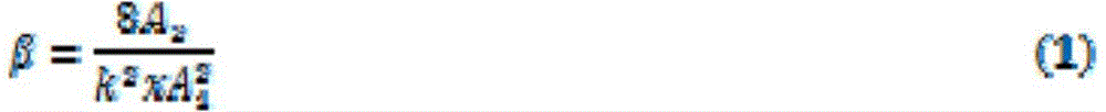
进一步地,非线性超声波检测过程为:超声波信号激发过程和线性超声波一样,同样设置两个路经检测,不同的是非线性超声波使用的两个传感器峰值频率必须为两倍关系,非线性超声波对亚波长的微观缺陷非常敏感其中二次谐波产生的方法是非线性超声波检测的一种,二次谐波是基于材料的非线性弹性相关的二次谐波频率分量产生的,微观结构的非均匀性引起非线弹性,材料的不均匀性可以通过声学非线性参数β来量化,参数使用基波和二次谐波振幅计算:Furthermore, the nonlinear ultrasonic detection process is as follows: the ultrasonic signal excitation process is the same as that of the linear ultrasonic wave, and two path detections are also set up. The difference is that the peak frequencies of the two sensors used by the nonlinear ultrasonic wave must be twice the relationship. Microscopic defects of wavelength are very sensitive. The second harmonic generation method is a kind of nonlinear ultrasonic testing. The second harmonic is generated based on the second harmonic frequency component related to the nonlinear elasticity of the material. The non-uniformity of the microstructure Inducing nonlinear elasticity, the inhomogeneity of the material can be quantified by the acoustic nonlinearity parameter β, calculated using the fundamental and second harmonic amplitudes:
二次谐波的声学非线性参数来表征非线性:Acoustic nonlinear parameters of the second harmonic to characterize the nonlinearity:
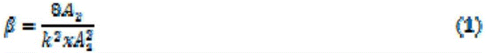
式中A1为基波电压振幅;第A2为二次谐波电压振幅,x为传播距离,k为波数。In the formula, A1 is the fundamental wave voltage amplitude; A2 is the second harmonic voltage amplitude, x is the propagation distance, and k is the wave number.
进一步地,传感器阵列的外侧设置有聚乙烯胶层,聚乙烯胶层包裹在传感器阵列和套筒壳体的外侧,传感器阵列包括若干组缺陷检测传感器,每组缺陷检测传感器之间间隔设置,每组缺陷检测传感器包括激发器和接收器,激发器和接收器相对设置;Further, the outer side of the sensor array is provided with a polyethylene adhesive layer, and the polyethylene adhesive layer is wrapped on the outer side of the sensor array and the sleeve housing. The sensor array includes several groups of defect detection sensors, and each group of defect detection sensors is arranged at intervals. The group defect detection sensor includes an exciter and a receiver, and the exciter and the receiver are arranged relatively;
灌浆口包括灌浆入口和灌浆出口,灌浆入口和灌浆出口分别设置在套筒壳体的两端,且设置在同一侧上,套筒壳体的两端设置有连接螺纹口,套筒壳体的内部设置有中心钢筋。The grouting port includes a grouting inlet and a grouting outlet, the grouting inlet and the grouting outlet are respectively arranged at both ends of the sleeve shell, and are arranged on the same side, the two ends of the sleeve shell are provided with connecting threaded ports, the sleeve shell The interior is provided with a central steel bar.
本发明由于采用了上述技术方案,具有以下有益效果:The present invention has the following beneficial effects due to the adoption of the above technical solution:
本发明所提出的基于超声波检测的智能灌浆套筒装置,具有绿色、高效、安全、成本低,使用寿命长的特点,且不受时间周围环境限制的特点,对传统的超声波无损检测方式进行了改进,使其具备更准确的检测能力,对环境变化有更强的适应性,另外超声波激发和示波器系统能激发不同类型的超声波信号,对与计算单元得出结果能够进行更丰富的数据对比,不同类型的波形对检测不同材料,材料形状,检测环境等有不同的分辨率从而实现分析的多样性,将压电陶瓷传感器和灌浆套筒结合起来,应用于实际工程中,从而起到监测的作用,将超声波检测运用于装配式建筑节点连接的灌浆套筒中,实现了对灌浆套筒内部缺陷的检测,能有效评估建筑节点的安全性,使结构更可靠。The intelligent grouting sleeve device based on ultrasonic detection proposed by the present invention has the characteristics of green, high efficiency, safety, low cost and long service life, and is not limited by time and surrounding environment. Improvement, so that it has more accurate detection capabilities and stronger adaptability to environmental changes. In addition, the ultrasonic excitation and oscilloscope system can excite different types of ultrasonic signals, and the results obtained by the calculation unit can be compared with richer data. Different types of waveforms have different resolutions for the detection of different materials, material shapes, detection environments, etc., so as to achieve the diversity of analysis. The combination of piezoelectric ceramic sensors and grouting sleeves is applied to actual projects, so as to play a role in monitoring. Function, the application of ultrasonic testing to the grouting sleeve connected to the joint of the prefabricated building realizes the detection of internal defects of the grouting sleeve, which can effectively evaluate the safety of the building joint and make the structure more reliable.
附图说明Description of drawings
图1是本发明系统结构示意图;Fig. 1 is a schematic structural diagram of the system of the present invention;
图2是本发明套筒横向剖面图;Fig. 2 is a cross-sectional view of the sleeve of the present invention;
图3是本发明套筒水平泡面图;Fig. 3 is the horizontal bubble noodle diagram of sleeve of the present invention;
图4是图3的3-3剖面图;Fig. 4 is a 3-3 sectional view of Fig. 3;
图5是本发明套筒立体图;Fig. 5 is a perspective view of the sleeve of the present invention;
图6是本发明非线性超声波检测实列图。Fig. 6 is a real sequence diagram of nonlinear ultrasonic detection in the present invention.
附图中,A-内部感知单元,B-激发显示单元,C-计算单元,D-信号传输单元,1-套筒壳体,2-灌浆口,3-激发器,4-接收器,5-超声波信号,6-传感器阵列,7-聚乙烯胶层,8-中心钢筋,9-缺陷,10-连接螺纹口,11-底梁,12-剪力墙,13-传输线预留管,14-砂浆密封接缝,15-波形激发器,16-示波器。In the drawings, A-internal perception unit, B-excitation display unit, C-calculation unit, D-signal transmission unit, 1-sleeve shell, 2-grouting port, 3-stimulator, 4-receiver, 5 -Ultrasonic signal, 6-sensor array, 7-polyethylene glue layer, 8-central steel bar, 9-defect, 10-connecting screw hole, 11-bottom beam, 12-shear wall, 13-transmission line reserved pipe, 14 - Mortar-sealed joints, 15 - waveform exciter, 16 - oscilloscope.
具体实施方式Detailed ways
为使本发明的目的、技术方案及优点更加清楚明白,以下参照附图并举出优选实施例,对本发明进一步详细说明。然而,需要说明的是,说明书中列出的许多细节仅仅是为了使读者对本发明的一个或多个方面有一个透彻的理解,即便没有这些特定的细节也可以实现本发明的这些方面。In order to make the object, technical solution and advantages of the present invention clearer, the present invention will be described in further detail below with reference to the accompanying drawings and preferred embodiments. However, it should be noted that many of the details listed in the specification are only for readers to have a thorough understanding of one or more aspects of the present invention, and these aspects of the present invention can be implemented even without these specific details.
如图1所示,一种内建环形超声波传感器阵列的智能灌浆套筒系统,包括内部感知单元A、激发显示单元B、计算单元C和信号传输单元D,激发显示单元B通过信号传输单元D与内部感知单元A连接,计算单元C与激发显示单元B连接,内部感知单元A用于实时感知内部的结构的信号并通过信号传输单元D传给激发显示单元B进行显示,最后传给计算单元C进行计算。As shown in Figure 1, an intelligent grouting sleeve system with a built-in annular ultrasonic sensor array includes an internal perception unit A, an excitation display unit B, a calculation unit C, and a signal transmission unit D, and the excitation display unit B passes through the signal transmission unit D It is connected with the internal perception unit A, and the calculation unit C is connected with the excitation display unit B. The internal perception unit A is used to sense the internal structure signal in real time and transmits it to the excitation display unit B for display through the signal transmission unit D, and finally transmits it to the calculation unit C performs calculations.
基于超声波检测原理,提出了开发一种基于超声波检测的智能灌浆套筒就可以有效的实现套筒内部各种类型缺陷的快速识别与评价,具体是通过在灌浆套筒管壁外贴上压电陶瓷传感器(PZT)阵列,并将这些传感器用聚乙烯胶包裹密封在套筒表面起来并将灌浆套筒预埋到混凝土中,传感器通过预留的管线连接到专业的超声波设备上,只需要在设备激发一定频率超声波信号,传感器就能接收到,并分析信号的到达时间(TOF)、能量、熵等数值就可以评估其缺陷。本发明是为了检测套筒内部产生的所有类型缺陷,这种自检测方法操作简单、成本低、绿色化。Based on the principle of ultrasonic testing, it is proposed that the development of an intelligent grouting sleeve based on ultrasonic testing can effectively realize the rapid identification and evaluation of various types of defects inside the sleeve. Ceramic sensor (PZT) array, and these sensors are wrapped and sealed on the surface of the sleeve with polyethylene glue, and the grouting sleeve is pre-embedded in the concrete. The sensor is connected to the professional ultrasonic equipment through the reserved pipeline. The equipment excites a certain frequency of ultrasonic signals, and the sensor can receive them, and analyze the signal's time of arrival (TOF), energy, entropy and other values to evaluate its defects. The invention aims to detect all types of defects generated inside the sleeve, and the self-inspection method is simple in operation, low in cost and green.
在灌浆套筒缺陷检测中,无论是有损检测或者无损检测,超声波检测是一种经济、高效的方式,可以在不破坏构件情况下评估其缺陷,对于将传感器设置在套筒壁并埋置混凝土构件中,设置这种内置传感器可以更加接近缺陷源,从而有效降低其他噪音的影响,对后续的检测也是能直接将传感器线连至激发设备上即可,有效降低检测成本,提高了经济效益。其中智能灌浆套筒检测是对其内部缺陷进行自检测并评估建筑节点安全性的重要装置。超声波探伤是利用材料及其缺陷的声学性能差异对超声波传播波形反射情况和穿透时间的能量变化来检验材料内部缺陷的无损检测方法,压电陶瓷传感器将超声波信号转化为电信号的原理进行检测,本发明的系统主要由四组环形传感器阵列构成,其中每组阵列由四个传感器、并辅以外部专业超声波检测设备、灌浆套筒等组成,检测过程只需将预留的传感器信号输出端口连接至外部专业超声波设备上即可,检测设备安装方便。超声波检测和其他检测方式最大的区别在于其能高效无损地对内部缺陷进行检测并评估,设置在套筒比上的几组呈现螺旋状的传感器阵列,实现了对各种类型缺陷和各种缺陷所在位置的有效检测,提高了其可检测性。In the detection of grouting sleeve defects, whether it is destructive testing or non-destructive testing, ultrasonic testing is an economical and efficient way to evaluate its defects without destroying components. In concrete components, setting this kind of built-in sensor can be closer to the defect source, thereby effectively reducing the influence of other noises. For subsequent detection, the sensor line can be directly connected to the excitation device, which can effectively reduce the detection cost and improve economic benefits. . Among them, the intelligent grouting sleeve inspection is an important device for self-inspection of its internal defects and evaluation of the safety of building nodes. Ultrasonic flaw detection is a non-destructive testing method that uses the difference in acoustic properties of materials and their defects to detect the internal defects of materials based on the energy changes in the reflection of ultrasonic wave propagation and penetration time. The piezoelectric ceramic sensor converts ultrasonic signals into electrical signals for detection. , the system of the present invention is mainly composed of four groups of annular sensor arrays, wherein each group of arrays is composed of four sensors, supplemented by external professional ultrasonic detection equipment, grouting sleeves, etc., the detection process only needs to output the reserved sensor signal output port It only needs to be connected to external professional ultrasonic equipment, and the detection equipment is easy to install. The biggest difference between ultrasonic testing and other testing methods is that it can detect and evaluate internal defects efficiently and non-destructively. Several sets of spiral sensor arrays arranged on the sleeve ratio realize the detection of various types of defects and various defects. The effective detection of the location improves its detectability.
此外,其他无损检测方式,其中最常见的X射线检测、涡流检测、CT三维扫描,这些方法效率低,成本高。尽管也有将传感器预埋至套筒内部的方法,但是因为套筒内部复杂性,灌浆时可能会损坏传感器,传感器也不容易将信号传输线拉出,总的说就是安装繁琐,不确定性高,也不宜使用这类方法。由聚乙烯胶包裹保护下,套筒表面的传感器不仅从一定程度上可以安全有效的激发超声波信号,更可以为传感器提供有效的耦合方式,最大化的提高信噪比。In addition, other non-destructive testing methods, the most common of which are X-ray testing, eddy current testing, and CT three-dimensional scanning, these methods have low efficiency and high cost. Although there is also a method to pre-embed the sensor inside the sleeve, due to the complexity of the inside of the sleeve, the sensor may be damaged during grouting, and the sensor is not easy to pull out the signal transmission line. Generally speaking, the installation is cumbersome and the uncertainty is high. Such methods should also not be used. Protected by polyethylene glue, the sensor on the surface of the sleeve can not only safely and effectively excite the ultrasonic signal to a certain extent, but also provide an effective coupling method for the sensor to maximize the signal-to-noise ratio.
本发明实施例中,内部感知单元A包括底梁11、剪力墙12和灌浆套筒,灌浆套筒设置在剪力墙12的内部,底梁11与剪力墙12连接处设置砂浆密封接缝14,灌浆套筒与底梁11连接。In the embodiment of the present invention, the internal sensing unit A includes a bottom beam 11, a shear wall 12 and a grouting sleeve, the grouting sleeve is arranged inside the shear wall 12, and a mortar sealing joint is provided at the joint between the bottom beam 11 and the shear wall 12.
本发明实施例中,信号传输单元D由分流器、超声波信号传输线和通用端口组成,其中通用端口能匹配超声波信号传输线。In the embodiment of the present invention, the signal transmission unit D is composed of a shunt, an ultrasonic signal transmission line and a general port, wherein the general port can match the ultrasonic signal transmission line.
本发明实施例中,计算单元C由电脑主机和显示器组成,电脑主机能运行智能算法计算超声波数据,智能算法是采用的自动提取超声波相关数据,对超声波滤波,计算到达时间、首波能量和熵的数据,其中计算超声波到达时间采用阈值法的循环进行提取,首波能量通过计算接收到的信号首波包络图的面积所得,熵的计算是基于香农熵的概率密度统计方法得到一个数值来表示该信号的熵值,将时间、首波能量和熵的数据与一个完整无缺陷的套筒数据进行比较就能得出结果。In the embodiment of the present invention, the calculation unit C is composed of a computer host and a display. The computer host can run an intelligent algorithm to calculate ultrasonic data. The intelligent algorithm is to automatically extract ultrasonic related data, filter ultrasonic waves, and calculate arrival time, first wave energy and entropy. The data, in which the calculation of the arrival time of the ultrasonic wave is extracted by the cycle of the threshold method, the energy of the first wave is obtained by calculating the area of the envelope diagram of the first wave of the received signal, and the calculation of the entropy is based on the probability density statistical method of Shannon entropy to get a value. Indicates the entropy value of the signal, and the result can be obtained by comparing the data of time, first wave energy and entropy with the data of a complete and non-defective sleeve.
本发明实施例中,激发显示单元B分别由任意波形激发器和超声波示波器组成,其中任意波形发生器装备高频和低频信号激发的接口,针对所需的激发频率进行检测。In the embodiment of the present invention, the excitation display unit B is composed of an arbitrary waveform exciter and an ultrasonic oscilloscope, wherein the arbitrary waveform generator is equipped with high-frequency and low-frequency signal excitation interfaces to detect the required excitation frequency.
本发明实施例中,如图2-5所示,灌浆套筒包括套筒壳体1、灌浆口2和传感器阵列6,套筒壳体1内部设置为空心结构,灌浆口2设置在套筒壳体1的侧边,传感器阵列6贴合设置在套筒壳体1的外侧。传感器阵列6包括四组传感器,每组传感器由四个压电陶瓷圆片传感器组成,第一组传感器负责检测水平管壁的集中缺陷,第二组传感器负责检测斜向水平缺陷,第一组传感器和第二组传感器均采用线性超声波,第三第二组传感器和第四组第二组传感器负责采用非线性超声波检测,非线性超声波分辨率相对线性超声波高。In the embodiment of the present invention, as shown in Figures 2-5, the grouting sleeve includes a
声源产生超声波,压电陶瓷传感器通过高频电压脉冲激励压电晶片时,发生逆压电效应,将电能转换为声能(机械能),探头激发超声波,然后超声波进入试件内。超声波在工件中传播并与工件材料以及其中的缺陷相互作用,使其传播方向或特征改变。改变后的超声波通过检测设备被接收,并可对其进行处理和分析。根据接收的超声波的特征,评估工件本身及其内部是否存在缺陷及缺陷的特性。The sound source generates ultrasonic waves, and when the piezoelectric ceramic sensor excites the piezoelectric wafer through high-frequency voltage pulses, the inverse piezoelectric effect occurs, converting electrical energy into acoustic energy (mechanical energy), the probe excites ultrasonic waves, and then the ultrasonic waves enter the specimen. Ultrasonic waves propagate in the workpiece and interact with the workpiece material and the defects in it, changing its direction of propagation or changing its characteristics. The changed ultrasonic waves are received by the detection equipment, and can be processed and analyzed. Based on the characteristics of the received ultrasonic waves, the workpiece itself and its interior are evaluated for defects and their characteristics.
线性超声波检测过程为:第一组传感器包括激发器和接收器,激发器和接收器都为压电陶瓷传感器,激发器经过高频脉冲激励压电晶片,将电能转换为声能,最后超声波经过套筒和内部缺陷使超声波信号的幅相发生变化,幅相变化通过激发和接收到的超声波波形反应,通过测量波的衰减,波速或者共振频率来检测材料缺陷,线性超声波检测中激发器和接收器使用的压电陶瓷传感器的峰值频率需要相同,信号的到达时间、首波能量比、信息熵都是通过编译好的智能算法计算,一个横截面上设置两个路径的超声波检测路径,一个经过缺陷,另一个没有经过缺陷,设置的这两个路径通过智能算法数据对比,有效评估内部缺陷。The linear ultrasonic detection process is as follows: the first group of sensors includes an exciter and a receiver, both of which are piezoelectric ceramic sensors, and the exciter excites the piezoelectric chip through a high-frequency pulse to convert electrical energy into acoustic energy, and finally the ultrasonic wave passes through The sleeve and internal defects change the amplitude and phase of the ultrasonic signal. The amplitude and phase changes are reflected by the excitation and received ultrasonic waveforms, and the material defects are detected by measuring the attenuation, wave velocity or resonance frequency of the wave. The exciter and receiver in linear ultrasonic testing The peak frequency of the piezoelectric ceramic sensor used in the sensor needs to be the same. The arrival time of the signal, the energy ratio of the first wave, and the information entropy are all calculated by the compiled intelligent algorithm. Two ultrasonic detection paths are set on one cross section, and one passes through Defects, and the other without defects, the two paths set are compared with intelligent algorithm data to effectively evaluate internal defects.
非线性超声波检测过程为:超声波信号激发过程和线性超声波一样,同样设置两个路经检测,不同的是非线性超声波使用的两个传感器峰值频率必须为两倍关系,非线性超声波对亚波长的微观缺陷非常敏感其中二次谐波产生的方法是非线性超声波检测的一种,二次谐波是基于材料的非线性弹性相关的二次谐波频率分量产生的,微观结构的非均匀性引起非线弹性,材料的不均匀性可以通过声学非线性参数β来量化,参数使用基波和二次谐波振幅计算:The nonlinear ultrasonic detection process is as follows: the ultrasonic signal excitation process is the same as the linear ultrasonic wave, and two path detections are also set up. The difference is that the peak frequency of the two sensors used by the nonlinear ultrasonic wave must be twice the relationship. Defects are very sensitive. The second harmonic generation method is a kind of nonlinear ultrasonic testing. The second harmonic is generated based on the second harmonic frequency component related to the nonlinear elasticity of the material. The non-uniformity of the microstructure causes nonlinear Elasticity, the inhomogeneity of the material, can be quantified by the acoustic nonlinear parameter β, calculated using the fundamental and second harmonic amplitudes:
二次谐波的声学非线性参数来表征非线性:Acoustic nonlinear parameters of the second harmonic to characterize the nonlinearity:
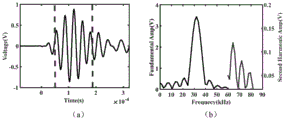
式中A1为基波电压振幅;第A2为二次谐波电压振幅,x为传播距离,k为波数。图6(b)为快速傅里叶变换(FFT)计算得到的接收信号频谱图中标出来基波和二次谐波。x为传播距离是恒定的(本文为不同路径的传感器距离);k为波数,由激励信号源控制,对每个样本来说都是恒定的。In the formula, A1 is the fundamental wave voltage amplitude; A2 is the second harmonic voltage amplitude, x is the propagation distance, and k is the wave number. Fig. 6(b) shows the fundamental wave and the second harmonic in the frequency spectrum of the received signal calculated by Fast Fourier Transform (FFT). x is the propagation distance is constant (in this paper, it is the sensor distance of different paths); k is the wave number, which is controlled by the excitation signal source and is constant for each sample.
本发明实施例中,传感器阵列6的外侧设置有聚乙烯胶层,聚乙烯胶层包裹在传感器阵列6和套筒壳体1的外侧,传感器阵列6包括若干组缺陷检测传感器,每组缺陷检测传感器之间间隔设置,每组缺陷检测传感器包括激发器3和接收器4,激发器3和接收器4相对设置。In the embodiment of the present invention, the outer side of the
灌浆口2包括灌浆入口和灌浆出口,灌浆入口和灌浆出口分别设置在套筒壳体1的两端,且设置在同一侧上,套筒壳体1的两端设置有连接螺纹口10,套筒壳体1的内部设置有中心钢筋8。The
其中传感器是由四组每组四个的压电陶瓷圆片传感器组成,直径为20mm,厚度为2mm,如图2和图3所示传感器需螺旋状布置在套筒壁外并用3mm厚聚乙烯胶将其包裹密封,将传感器传输线通过预留管道拉出如图1所示,采用峰值频率为600kHz和1.2MHz,因为超声波在套筒中的波速大致为4300m/s,能容纳的波长为7.17mm的波长所以缺陷厚度一般为波长的一半合适,并且每组超声波传感器由一对600kHz做线性超声波检测,一组600kHz和1.2MHz的传感器做非线性超声波检测,这是考虑到缺陷厚度大小的问题,第一组负责检测水平管壁的集中缺陷,第二组负责检测斜向水平缺陷,前两组采用线性超声波,第三第四组负责采用非线性超声波检测,而且非线性超声波分辨率相对线性超声波较高;Among them, the sensor is composed of four groups of four piezoelectric ceramic disc sensors, with a diameter of 20mm and a thickness of 2mm. As shown in Figure 2 and Figure 3, the sensor should be arranged spirally outside the sleeve wall and made of 3mm thick polyethylene. Seal it with glue, and pull out the sensor transmission line through the reserved pipe as shown in Figure 1. The peak frequencies are 600kHz and 1.2MHz, because the wave velocity of ultrasonic waves in the sleeve is roughly 4300m/s, and the wavelength that can be accommodated is 7.17 mm wavelength, so the thickness of the defect is generally half of the wavelength, and each group of ultrasonic sensors has a pair of 600kHz for linear ultrasonic detection, and a group of 600kHz and 1.2MHz sensors for nonlinear ultrasonic detection, which is considering the thickness of the defect. , the first group is responsible for detecting concentrated defects on the horizontal pipe wall, the second group is responsible for detecting oblique horizontal defects, the first two groups use linear ultrasonic, the third and fourth groups are responsible for non-linear ultrasonic detection, and the resolution of nonlinear ultrasonic is relatively linear Ultrasound is higher;
灌浆套筒按照《JGT398-2012钢筋连接用灌浆套筒》和《JGJ钢筋套筒灌浆连接应用技术规程》规范制作,灌浆套筒在底部埋置集中缺陷,紧贴钢筋周围的分散缺陷,呈螺旋条状分布的斜缺陷,这是为了模拟在套筒内部产生的缺陷,其中缺陷大小厚度根据传感器激发的频率而定;3.信号传输分别由分流器、超声波信号传输线和通用端口组成,其中通用端口能匹配各类超声波信号传输线4.外部计算系统由电脑主机和显示器组成,电脑主机能运行智能算法计算超声波数据,智能算法是采用的自动提取超声波相关数据,对超声波滤波,计算到达时间(TOF)、首波能量、熵等数据。其中计算超声波到达时间采用了阈值法的循环进行提取,首波能量是算法计算了接收到的信号首波包络图的面积所得。熵的计算是基于香农熵的概率密度统计方法得到一个数值来表示该信号的熵值。将这些数据与一个完整无缺陷的套筒数据进行比较就能得出结果。The grouting sleeve is manufactured in accordance with the specifications of "JGT398-2012 Grouting Sleeve for Rebar Connection" and "JGJ Application Technical Regulations for Reinforcement Sleeve Grouting Connection". Oblique defects distributed in stripes, this is to simulate the defects generated inside the sleeve, where the size and thickness of the defects are determined according to the excitation frequency of the sensor; 3. The signal transmission consists of a shunt, an ultrasonic signal transmission line and a general port, of which the general The port can match all kinds of ultrasonic signal transmission lines. 4. The external computing system is composed of a host computer and a display. The host computer can run an intelligent algorithm to calculate ultrasonic data. The intelligent algorithm is used to automatically extract ultrasonic related data, filter ultrasonic waves, and calculate time of arrival (TOF ), first wave energy, entropy and other data. Among them, the calculation of the ultrasonic arrival time adopts the cycle of the threshold method to extract, and the energy of the first wave is obtained by calculating the area of the envelope diagram of the first wave of the received signal by the algorithm. The calculation of entropy is based on the probability density statistics method of Shannon entropy to obtain a value to represent the entropy value of the signal. Comparing these data with the data of a complete, defect-free sleeve yields the results.
工作机制介绍:将贴有四组直径方向每组4个传感器的灌浆套筒表面提前于埋至剪力墙和柱子中,传感器线路通过预留的管道连到超声波激发器和示波器上,超声波波形激发器激发600kHz的超声波信号,由同一组对侧的传感器接收并在示波器上显示,通过智能算法将示波器上的波形数据导出并分析其到达时间(TOF)、首波能量、熵等等,将这些数据与一个完整无缺陷的套筒数据进行比较就能得出结果。Introduction to the working mechanism: The surface of the grouting sleeve with four sets of 4 sensors in the diameter direction is buried in the shear wall and the column in advance, and the sensor line is connected to the ultrasonic exciter and oscilloscope through the reserved pipe, and the ultrasonic waveform The exciter excites a 600kHz ultrasonic signal, which is received by the same group of sensors on the opposite side and displayed on the oscilloscope. The waveform data on the oscilloscope is exported and analyzed by an intelligent algorithm, such as time of arrival (TOF), energy of the first wave, entropy, etc. These data are compared with the data of a complete and defect-free sleeve to obtain the results.
所提出的发明中,智能检测灌浆套筒是通过设置在套筒壁上螺旋分布的压电陶瓷传感器来实现的,这套系统是由激发显示单元、感知单元、信号传输单元、外部分析处理系统单元构成;其中激发显示单元是由波形激发器激发信号,感知单元是由接收信号的传感器接收并显示在示波器上;而外部分析处理系统单元是由计算机收集示波器数据,功能包括数据采集、计算分析。智能检测灌浆套筒如图2所示,设置了4组传感器在套筒壁表面,每组有两个传感器激发两个接收,传感器激发和接收就是通过每组传感器实现的。In the proposed invention, the intelligent detection of the grouting sleeve is realized by means of piezoelectric ceramic sensors arranged in a spiral distribution on the sleeve wall. This system is composed of an excitation display unit, a sensing unit, a signal transmission unit, and an external analysis and processing system The excitation display unit is composed of a waveform exciter to stimulate the signal, the sensing unit is received by the sensor receiving the signal and displayed on the oscilloscope; the external analysis and processing system unit is a computer that collects oscilloscope data, and its functions include data acquisition, calculation and analysis . The intelligent detection grouting sleeve is shown in Figure 2. Four sets of sensors are set on the surface of the sleeve wall. Each set has two sensors to stimulate and two receivers. The sensor excitation and reception are realized through each set of sensors.
以上所述仅是本发明的优选实施方式,应当指出,对于本技术领域的普通技术人员来说,在不脱离本发明原理的前提下,还可以作出若干改进和润饰,这些改进和润饰也应视为本发明的保护范围。The above is only a preferred embodiment of the present invention, it should be pointed out that for those of ordinary skill in the art, without departing from the principle of the present invention, some improvements and modifications can also be made, and these improvements and modifications should also be It is regarded as the protection scope of the present invention.
Claims (10)

Priority Applications (1)
| Application Number | Priority Date | Filing Date | Title |
|---|---|---|---|
| CN202211730659.3A CN116026921A (en) | 2022-12-30 | 2022-12-30 | An intelligent grouting sleeve system with a built-in annular ultrasonic sensor array |
Applications Claiming Priority (1)
| Application Number | Priority Date | Filing Date | Title |
|---|---|---|---|
| CN202211730659.3A CN116026921A (en) | 2022-12-30 | 2022-12-30 | An intelligent grouting sleeve system with a built-in annular ultrasonic sensor array |
Publications (1)
| Publication Number | Publication Date |
|---|---|
| CN116026921A true CN116026921A (en) | 2023-04-28 |
Family
ID=86073621
Family Applications (1)
| Application Number | Title | Priority Date | Filing Date |
|---|---|---|---|
| CN202211730659.3A Pending CN116026921A (en) | 2022-12-30 | 2022-12-30 | An intelligent grouting sleeve system with a built-in annular ultrasonic sensor array |
Country Status (1)
| Country | Link |
|---|---|
| CN (1) | CN116026921A (en) |
Cited By (1)
| Publication number | Priority date | Publication date | Assignee | Title |
|---|---|---|---|---|
| CN116486021A (en) * | 2023-06-25 | 2023-07-25 | 天津医科大学总医院 | Three-dimensional model construction method and system based on CT density value and ultrasonic gray value |
-
2022
- 2022-12-30 CN CN202211730659.3A patent/CN116026921A/en active Pending
Cited By (2)
| Publication number | Priority date | Publication date | Assignee | Title |
|---|---|---|---|---|
| CN116486021A (en) * | 2023-06-25 | 2023-07-25 | 天津医科大学总医院 | Three-dimensional model construction method and system based on CT density value and ultrasonic gray value |
| CN116486021B (en) * | 2023-06-25 | 2023-08-18 | 天津医科大学总医院 | Three-dimensional model construction method and system based on CT density value and ultrasonic gray value |
Similar Documents
| Publication | Publication Date | Title |
|---|---|---|
| Liu et al. | Interfacial debonding detection for CFST structures using an ultrasonic phased array: Application to the Shenzhen SEG building | |
| CN101539541B (en) | Detection method of thick beam structure damage based on guide wave | |
| CN102944608B (en) | Device and method for ultrasonic testing of corrugated pipe duck grouting compactness | |
| CN103604868B (en) | Bellows Grouting Quality Detection Device and Method Based on Synthetic Aperture and Information Entropy | |
| Krause et al. | Elastic wave modes for the assessment of structural timber: ultrasonic echo for building elements and guided waves for pole and pile structures | |
| CN112098512B (en) | A detection method for grouting sleeve grouting defects based on acoustic local resonance scattering characteristics | |
| CN109470769B (en) | Method and system for detecting sleeve grouting fullness by ultrasonic reflection method | |
| CN107561123A (en) | A kind of beams of concrete damage monitoring system and monitoring method | |
| CN103852492A (en) | Monitoring method for grouting compaction of pre-stressed pipe based on piezoelectric ceramic | |
| CN102967657A (en) | Nondestructive testing method based on synthetic aperture ultrasonic imaging technique | |
| Stepinski | Novel instrument for inspecting rock bolt integrity using ultrasonic guided waves | |
| Im et al. | Non-destructive testing methods to identify voids in external post-tensioned tendons | |
| CN103995051A (en) | Testing device and testing method for recognizing weld defects of orthotropic steel bridge deck slab | |
| CN116735714B (en) | A method for testing the void defects of steel box concrete shear wall | |
| CN111678465B (en) | Pipeline bending detection method based on ultrasonic guided waves | |
| Fierro et al. | Nonlinear imaging (NIM) of flaws in a complex composite stiffened panel using a constructive nonlinear array (CNA) technique | |
| CN106053602A (en) | A self-closed rock bolt nondestructive testing method based on a magnetostrictive effect | |
| CN101750035B (en) | Non-destructive testing method and testing device for the length of anchor bolt | |
| Jiao et al. | Low-frequency vibration modulation of guided waves to image nonlinear scatterers for structural health monitoring | |
| CN116026921A (en) | An intelligent grouting sleeve system with a built-in annular ultrasonic sensor array | |
| CN218911991U (en) | Intelligent grouting sleeve with built-in annular ultrasonic sensor array | |
| CN114062506B (en) | Air coupling ultrasonic damage imaging system based on non-collinear frequency mixing technology and imaging method thereof | |
| CN203069556U (en) | Ultrasonic detection device for highway steel bridge | |
| CN106501285A (en) | The equipment of the mud jacking degree of compaction of Non-Destructive Testing prestress pipe and detection method | |
| He et al. | Health monitoring of rock bolts using ultrasonic guided waves |
Legal Events
| Date | Code | Title | Description |
|---|---|---|---|
| PB01 | Publication | ||
| PB01 | Publication | ||
| SE01 | Entry into force of request for substantive examination | ||
| SE01 | Entry into force of request for substantive examination |