CN115967947A - Intermodulation product interference determination method and device, electronic equipment and readable storage medium - Google Patents
Intermodulation product interference determination method and device, electronic equipment and readable storage medium Download PDFInfo
- Publication number
- CN115967947A CN115967947A CN202310244979.6A CN202310244979A CN115967947A CN 115967947 A CN115967947 A CN 115967947A CN 202310244979 A CN202310244979 A CN 202310244979A CN 115967947 A CN115967947 A CN 115967947A
- Authority
- CN
- China
- Prior art keywords
- matrix
- order intermodulation
- frequency
- target
- intermodulation product
- Prior art date
- Legal status (The legal status is an assumption and is not a legal conclusion. Google has not performed a legal analysis and makes no representation as to the accuracy of the status listed.)
- Granted
Links
Images


Classifications
-
- Y—GENERAL TAGGING OF NEW TECHNOLOGICAL DEVELOPMENTS; GENERAL TAGGING OF CROSS-SECTIONAL TECHNOLOGIES SPANNING OVER SEVERAL SECTIONS OF THE IPC; TECHNICAL SUBJECTS COVERED BY FORMER USPC CROSS-REFERENCE ART COLLECTIONS [XRACs] AND DIGESTS
- Y02—TECHNOLOGIES OR APPLICATIONS FOR MITIGATION OR ADAPTATION AGAINST CLIMATE CHANGE
- Y02D—CLIMATE CHANGE MITIGATION TECHNOLOGIES IN INFORMATION AND COMMUNICATION TECHNOLOGIES [ICT], I.E. INFORMATION AND COMMUNICATION TECHNOLOGIES AIMING AT THE REDUCTION OF THEIR OWN ENERGY USE
- Y02D30/00—Reducing energy consumption in communication networks
- Y02D30/70—Reducing energy consumption in communication networks in wireless communication networks
Landscapes
- Mobile Radio Communication Systems (AREA)
Abstract
The invention provides an intermodulation product interference determination method, an intermodulation product interference determination device, electronic equipment and a readable storage medium, and relates to the technical field of communication, wherein the method comprises the following steps: acquiring signal source power, a first frequency range of uplink frequency, downlink center frequency and frequency bandwidth of each base station in L base stations, and a coefficient matrix of an n-order intermodulation product; generating a target central frequency matrix based on the downlink central frequency and the coefficient matrix of each base station; generating a target bandwidth matrix based on the frequency bandwidth and the coefficient matrix of each base station; calculating a second frequency range of the n-order intermodulation product based on the target center frequency matrix and the target bandwidth matrix; in case of an overlapping area of the second frequency range and the first frequency range, an interference noise value of the n-order intermodulation product is calculated based on the first frequency range, the second frequency range and the signal source power. The invention calculates through coefficient matrix, target center frequency matrix and target bandwidth matrix, reduce and confirm the time of intermodulation product interference.
Description
Technical Field
The invention relates to the technical field of communication, in particular to an intermodulation product interference determination method, an intermodulation product interference determination device, electronic equipment and a readable storage medium.
Background
In an indoor signal distribution system, intermodulation products are generated due to the presence of different signal source inputs, and there may be overlapping frequency ranges of the intermodulation products and the upstream frequencies of the signal sources, which may interfere with communications. In the related art, a serial loop algorithm is used to calculate the interference of each intermodulation product. However, as the number of input signal sources increases, the types of intermodulation products also increase, including 2 nd order intermodulation products, 3 rd order intermodulation products, and 5 th order intermodulation products (2 nd order intermodulation products are intermodulation products generated by two signal sources, 3 rd order intermodulation products are intermodulation products generated by three signal sources, and 5 th order intermodulation products are intermodulation products generated by five signal sources). In the related art, due to the adoption of serial calculation by a loop algorithm, the calculation amount is large when the interference of the third-order intermodulation product and the interference of the fifth-order intermodulation product are calculated, so that the time for determining the interference of the intermodulation products is long.
It can be seen that there is a problem in the prior art that the time for determining the intermodulation product interference is long.
Disclosure of Invention
The embodiment of the invention provides an intermodulation product interference determination method, an intermodulation product interference determination device, electronic equipment and a readable storage medium, and aims to solve the problem that in the prior art, the time for determining the intermodulation product interference is long.
In order to solve the problems, the invention is realized as follows:
in a first aspect, an embodiment of the present invention provides a method for determining intermodulation product interference, where the method includes:
the method comprises the steps of obtaining signal source power, a first frequency range of uplink frequency, downlink center frequency and frequency bandwidth corresponding to the downlink center frequency of each base station in L base stations, and a coefficient matrix of n-order intermodulation products, wherein the n-order intermodulation products are intermodulation products generated by n signal sources in the L base stations through interaction, the coefficient matrix is used for representing calculation coefficients of the signal sources corresponding to the n-order intermodulation products, L is a positive integer larger than 2, n is a positive integer 2, 3 or 5, and n is smaller than L, and each row in the coefficient matrix is used for representing coefficients of n signal sources corresponding to one n-order intermodulation product;
generating an initial central frequency matrix based on the downlink central frequency of each base station, wherein each column of the initial central frequency matrix is used for representing the downlink central frequencies of n signal sources corresponding to one n-order intermodulation product;
multiplying the initial center frequency matrix and the coefficient matrix to generate a target center frequency matrix, wherein the target center frequency matrix is used for representing the frequencies of n-order intermodulation products generated by n signal sources in the L base stations;
generating a target bandwidth matrix based on the frequency bandwidth of each base station, the initial center frequency matrix and the coefficient matrix, wherein the target bandwidth matrix is used for representing the frequency bandwidth of n-order intermodulation products generated by n signal sources in the L base stations, and the positions of the target bandwidth matrix and the target center frequency matrix in the same row and column correspond to the same signal source;
calculating a second frequency range of the n-order intermodulation products based on the target center frequency matrix, the target bandwidth matrix;
calculating an interference noise value of the n-order intermodulation products based on the first frequency range, the second frequency range and the signal source power, if there is an overlapping area between the second frequency range and the first frequency range, the interference noise value being used to characterize interference of the n-order intermodulation products with L signal sources;
determining coefficients of n signal sources of the n-order intermodulation products based on the number of rows of the n-order intermodulation products in the target center frequency matrix or the target bandwidth matrix and the coefficient matrix if the interference noise value corresponding to the n-order intermodulation products is greater than a set threshold;
determining downlink center frequencies of n signal sources of the n-order intermodulation products based on the number of columns of the n-order intermodulation products in the target center frequency matrix or the target bandwidth matrix and the initial center frequency matrix.
Optionally, the generating a target bandwidth matrix based on the frequency bandwidth of each base station, the initial center frequency matrix, and the coefficient matrix includes:
determining an initial bandwidth matrix based on the frequency bandwidth of each base station and the initial center frequency matrix, wherein the positions of the initial bandwidth matrix and the initial center frequency matrix in the same row and column correspond to the same signal source, and the initial bandwidth matrix is used for representing the frequency bandwidth of each base station in different n signal source combinations;
and multiplying the absolute value of the coefficient matrix and the initial bandwidth matrix to obtain a target bandwidth matrix of the n-order intermodulation product.
Optionally, the calculating an interference noise value of the n-order intermodulation product based on the first frequency range, the second frequency range, and the signal source power includes:
calculating a target intensity ratio based on the overlap region and the second frequency range, the target intensity ratio being used to characterize a signal power intensity ratio of the overlap region and the n-order intermodulation products;
calculating the power intensity of the n-order intermodulation product based on the coefficient matrix and the signal source power;
setting a product of the target intensity ratio and the power intensity of the n-order intermodulation products as the interference noise value.
Optionally, the calculating a target intensity ratio based on the overlap region and the second frequency range includes:
based on the overlapping area and the second frequency range, calculating a first ratio of the overlapping area in a first area of the second frequency range and a second ratio of the overlapping area in a second area of the second frequency range, wherein the first area and the second area are areas of the second frequency range, the first area is located on two sides of the second area, and the first area is larger than the second area;
setting the sum of the product of the first ratio and a first power ratio of the first area and the product of the second ratio and a second power ratio of the second area as the target intensity ratio, wherein the first power ratio is the same as the second power ratio.
Optionally, the calculating, based on the coefficient matrix and the signal source power, the power strength of the n-order intermodulation product includes:
obtaining an intermodulation suppression degree and a rated input carrier power of a tested device for receiving L signal sources, wherein the tested device is used for representing a device for receiving the signal source of each base station in the L base stations;
bringing the intermodulation suppression degree, the rated input carrier power, the coefficient matrix and the signal source power into a preset formula to obtain the power intensity of the n-order intermodulation product, wherein the preset formula comprises a first formula corresponding to the condition that n is 2 or 3 and a second formula corresponding to the condition that n is 5, and the power intensity of the n-order intermodulation product is calculated through the first formula and expressed as follows:

P RIM for the power strength, RIM is the intermodulation suppression degree, P 1 For said nominal input carrier power, O 1 To O n Is the coefficient, P f1 To P fn Is the signal source power;
the power strength of the n-th order intermodulation product is calculated by the second equation as follows:

and K is a constant.
Optionally, the calculating a second frequency range of the n-order intermodulation products based on the target center frequency matrix and the target bandwidth matrix includes:
calculating a first product value of the target bandwidth matrix and a first weighting value, and setting a difference value between the target center frequency matrix and the first product value as a minimum value of the second frequency range;
a second product value of the target bandwidth matrix and a second weight value is calculated, and a sum of the target center frequency matrix and the second product value is set as a maximum value of the second frequency range.
In a second aspect, an embodiment of the present invention further provides an intermodulation product interference determining apparatus, including:
an obtaining module, configured to obtain, for each base station of L base stations, signal source power, a first frequency range of an uplink frequency, a downlink central frequency, a frequency bandwidth corresponding to the downlink central frequency, and a coefficient matrix of an n-order intermodulation product, where the n-order intermodulation product is an intermodulation product generated by n signal sources in the L base stations through interaction, the coefficient matrix is used to represent a calculation coefficient of the signal source corresponding to the n-order intermodulation product, where L is a positive integer greater than 2, n is a positive integer 2, 3, or 5, and n is less than L, and each row in the coefficient matrix is used to represent coefficients of n signal sources corresponding to one n-order intermodulation product;
a first generating module, configured to generate an initial central frequency matrix based on a downlink central frequency of each base station, where each column of the initial central frequency matrix is used to represent downlink central frequencies of n signal sources corresponding to one n-order intermodulation product;
a second generating module, configured to multiply the initial center frequency matrix and the coefficient matrix to generate a target center frequency matrix, where the target center frequency matrix is used to characterize frequencies of n-order intermodulation products generated by n signal sources in the L base stations;
a third generating module, configured to generate a target bandwidth matrix based on the frequency bandwidth of each base station, the initial center frequency matrix, and the coefficient matrix, where the target bandwidth matrix is used to characterize frequency bandwidths of n-order intermodulation products generated by n signal sources in the L base stations, and the positions of the target bandwidth matrix and the target center frequency matrix in the same row and column correspond to the same signal source;
a first calculation module for calculating a second frequency range of the n-order intermodulation products based on the target center frequency matrix and the target bandwidth matrix;
a second calculating module, configured to calculate, based on the first frequency range, the second frequency range and the signal source power, an interference noise value of the n-order intermodulation product, where there is an overlapping area between the second frequency range and the first frequency range, and the interference noise value is used to characterize interference of the n-order intermodulation product on L signal sources;
a first processing module, configured to, if the interference noise value corresponding to the n-order intermodulation product is greater than a set threshold, determine coefficients of n signal sources of the n-order intermodulation product based on a number of rows of the n-order intermodulation product located in the target center frequency matrix or the target bandwidth matrix, and the coefficient matrix;
a second processing module, configured to determine downlink center frequencies of n signal sources of the n-order intermodulation products based on the number of columns of the n-order intermodulation products in the target center frequency matrix or the target bandwidth matrix and the initial center frequency matrix.
Optionally, the third generating module includes:
the first processing submodule is used for determining an initial bandwidth matrix based on the frequency bandwidth of each base station and the initial center frequency matrix, the positions of the initial bandwidth matrix and the initial center frequency matrix in the same row and column correspond to the same signal source, and the initial bandwidth matrix is used for representing the frequency bandwidth of each base station in different n signal source combinations;
and the second processing submodule is used for multiplying the absolute value of the coefficient matrix and the initial bandwidth matrix to obtain a target bandwidth matrix of the n-order intermodulation product.
Optionally, the second computing module includes:
a first calculation submodule, configured to calculate a target intensity ratio based on the overlap region and the second frequency range, where the target intensity ratio is used to characterize a signal power intensity ratio between the overlap region and the n-order intermodulation product;
the second calculation submodule is used for calculating the power intensity of the n-order intermodulation product based on the coefficient matrix and the signal source power;
a third calculation submodule for setting a product of the target intensity ratio and the power intensity of the n-order intermodulation products as the interference noise value.
Optionally, the first computing submodule includes:
a first calculating unit, configured to calculate, based on the overlapping area and the second frequency range, a first ratio of the overlapping area in a first area of the second frequency range and a second ratio of the overlapping area in a second area of the second frequency range, where the first area and the second area are areas of the second frequency range, the first area is located on two sides of the second area, and the first area is larger than the second area;
a second calculating unit, configured to set a sum of a product of the first ratio and a first power ratio of the first area and a product of the second ratio and a second power ratio of the second area as the target intensity ratio, where the first power ratio is the same as the second power ratio.
Optionally, the second computing submodule includes:
an obtaining unit, configured to obtain an intermodulation suppression degree and a rated input carrier power of a device under test that receives L signal sources, where the device under test is used to characterize a device that receives a signal source of each base station in the L base stations;
a third calculating unit, configured to bring the intermodulation suppression degree, the rated input carrier power, the coefficient matrix, and the signal source power into a preset formula, to obtain the power strength of the n-order intermodulation product, where the preset formula includes a first formula corresponding to the case where n is 2 or 3, and a second formula corresponding to the case where n is 5, where the power strength of the n-order intermodulation product is calculated through the first formula as follows:

P RIM for the power strength, RIM is the intermodulation suppression degree, P 1 For said nominal input carrier power, O 1 To O n Is the coefficient, P f1 To P fn Is the signal source power;
the power strength of the n-th order intermodulation products is calculated by the second equation as follows:

the K is a constant.
Optionally, the first computing module includes:
a fourth calculation submodule, configured to calculate a first product value of the target bandwidth matrix and the first weighting value, and set a difference between the target center frequency matrix and the first product value as a minimum value of the second frequency range;
a fifth calculation sub-module, configured to calculate a second product value of the target bandwidth matrix and a second weighting value, and set a sum of the target center frequency matrix and the second product value as a maximum value of the second frequency range.
In a third aspect, an embodiment of the present invention also provides an electronic device, including a processor, a memory, and a computer program stored on the memory and executable on the processor, where the computer program, when executed by the processor, implements the steps in the intermodulation product interference determination method according to the first aspect.
In a fourth aspect, an embodiment of the present invention further provides a readable storage medium for storing a program, where the program, when executed by a processor, implements the steps in the intermodulation product interference determination method as described in the first aspect.
In the embodiment of the invention, an initial central frequency matrix is generated based on the downlink central frequency of each base station; multiplying the initial central frequency matrix and the coefficient matrix to generate a target central frequency matrix; generating a target bandwidth matrix based on the frequency bandwidth, the initial center frequency matrix and the coefficient matrix of each base station; calculating a second frequency range of the n-order intermodulation product based on the target center frequency matrix and the target bandwidth matrix; under the condition that the second frequency range and the first frequency range have an overlapping region, calculating an interference noise value of an n-order intermodulation product based on the first frequency range, the second frequency range and the signal source power, and realizing that the interference noise value is calculated through a coefficient matrix, a target bandwidth matrix and a target central frequency matrix, wherein the coefficient matrix, the target bandwidth matrix and the target central frequency matrix can quickly locate the coefficient, the bandwidth and the frequency corresponding to the intermodulation product, so that the calculation speed is improved, and the time for determining the interference of the intermodulation product is shortened.
Drawings
To more clearly illustrate the technical solutions of the embodiments of the present invention, the drawings used in the description of the embodiments of the present invention will be briefly introduced below, and it is obvious that the drawings in the following description are only some embodiments of the present invention, and it is obvious for those skilled in the art to obtain other drawings based on these drawings without inventive labor.
Fig. 1 is a schematic diagram of intermodulation product generation provided by an embodiment of the present invention;
fig. 2 is a schematic diagram of intermodulation products and an uplink carrier signal provided by an embodiment of the present invention;
fig. 3 is a flowchart of an intermodulation product interference determination method according to an embodiment of the present invention;
fig. 4 is a schematic diagram illustrating intermodulation products and signal sources provided by an embodiment of the present invention without overlap;
fig. 5 is a schematic diagram of power distribution of uplink frequency and n-order intermodulation products of a base station according to an embodiment of the present invention;
fig. 6 is a schematic diagram of power distribution of n-order intermodulation products provided by an embodiment of the present invention;
fig. 7 is a block diagram of an intermodulation product interference determination apparatus according to an embodiment of the present invention;
fig. 8 is a block diagram of an electronic device according to an embodiment of the present invention.
Detailed Description
The technical solutions in the embodiments of the present invention will be clearly and completely described below with reference to the drawings in the embodiments of the present invention, and it is obvious that the described embodiments are some, not all, embodiments of the present invention. All other embodiments, which can be obtained by a person skilled in the art without inventive step based on the embodiments of the present invention, are within the scope of protection of the present invention.
In an indoor signal distribution system, as shown in fig. 1, at least two carrier signals (carrier signal F) exist in one transmission device 1 And a carrier signal F 2 ) In the case of (2), intermodulation products are generated due to carrier signal nonlinearity. The signal sources input to the antennas in the indoor signal distribution system include a plurality of, for example,

the interaction between the different signal sources generates intermodulation products. For a transmission device, intermodulation products can be detected in both uplink and downlink directions, but the intermodulation products in the uplink direction are received by other receivers in the uplink direction, and since the frequencies of the intermodulation products overlap with the frequencies of carrier signals in the uplink direction, as shown in fig. 2, the sensitivity of the receiver is affected by interference, and the intermodulation products causing the interference need to be determined to avoid continuously causing the interference. Because the matrix can quickly position the relevant parameters of each carrier signal, a large amount of calculation is avoided, the calculation speed can be improved, and the time for determining the intermodulation products causing the interference is shortened, as seen in the subsequent embodiment.
Referring to fig. 3, fig. 3 is a flowchart of an intermodulation product interference determination method according to an embodiment of the present invention, as shown in fig. 3, including the following steps:
The L base stations are base stations that provide carrier signals in an indoor signal distribution system. Each base station provides a downlink carrier signal and an uplink carrier signal, the frequency ranges of the carrier signals corresponding to different base stations are different, and the power of signal sources corresponding to different base stations is also different.
The n-order intermodulation products are intermodulation products generated by the interaction of different signal sources, and comprise 2-order intermodulation products, 3-order intermodulation products and 5-order intermodulation products. The frequency ranges of different 2-order intermodulation products generated by different signal sources through interaction are different, the frequency ranges of different 3-order intermodulation products generated by different signal sources through interaction are different, the frequency ranges of different 5-order intermodulation products generated by different signal sources through interaction are different, the frequency ranges among the 2-order intermodulation products, the 3-order intermodulation products and the 5-order intermodulation products are different, and in the interference determining process, the interference generated by each intermodulation product needs to be determined, which is detailed in the following embodiments.
The coefficient matrix is a calculation coefficient of a signal source corresponding to the n-order intermodulation product, and in the related art, the center frequency corresponding to the n-order intermodulation product is calculated and obtained by calculating the center frequency of the downlink carrier wave of the signal source corresponding to the calculation coefficient and the n-order intermodulation product. For example, the first signal source and the second signal source interact to generate a 2 nd order intermodulation product, and the center frequency of the 2 nd order intermodulation product can be calculated by the following formula one:
PIM 2 =O 1 ×f 1 +O 2 ×f 2 ;
wherein the PIM 2 Is the center frequency, f, of the 2 nd order intermodulation product 1 Is the center frequency, f, of the downstream carrier of the first signal source 2 Is the center frequency, O, of the downstream carrier of the second signal source 1 And O 2 In order to calculate the coefficients of the coefficients, 。
。
it should be understood that the co-operation between carrier signals of different base stations produces n-order intermodulation products, including 2-order intermodulation products, 3-order intermodulation products, and 5-order intermodulation products, whose corresponding coefficient matrices differ for the different n-order intermodulation products. Wherein the coefficient matrix O of the n-order intermodulation products m×n Expressed as formula two:

wherein, ,
, ,
, for calculating coefficients, there is @forany i>
 And &>
 ,
, Is an integer, and m is a positive integer greater than 0.
The first frequency range of the uplink frequency is the frequency range of the uplink carrier signal of the signal source of each base station in the L base stations, and comprises a starting frequency and a terminating frequency; the downlink central frequency is the central frequency of an uplink carrier signal of a signal source of each of the L base stations; the frequency bandwidth is the bandwidth of the uplink carrier signal of the signal source of each of the L base stations. It should be understood that the frequency range of each of the L base stations, including the start frequency and the end frequency, can be determined by the downlink center frequency and the frequency bandwidth. And determining a second frequency range of the intermodulation product through the downlink central frequency and the frequency bandwidth, further determining whether an overlapping part exists with the first frequency range of the uplink frequency, and adding the subsequent embodiments.
The initial central frequency matrix comprises downlink central frequencies of n signal source combinations in the L signal sources, and an n-order intermodulation product generated by each signal source combination, wherein the central frequencies of the n-order intermodulation products can be calculated through the downlink central frequencies and the calculation coefficients of the n signal sources in the signal source combinations.
Wherein the initial center frequency matrix F n×k Represented by the following formula three:

in the formula three, the first step is that, ,
, ,
, is the downlink center frequency of one signal source in the L signal sources, and k is the combined number of different signal sources for generating n-order intermodulation products. It should be understood that different n-order intermodulation products differ by n, as do the initial center frequency matrices they construct.
The target center frequency matrix includes frequencies corresponding to different n-order intermodulation products. It is understood that different n-order intermodulation products are differentThe signal sources interact to generate signals, and the center frequencies of the signals are different. Because there are L signal sources of the base station, intermodulation products may be generated between different signal sources, so the number of different intermodulation products is also different. For example, there is a total in an indoor signal distribution system Second order intermodulation products->
 A third order intermodulation product and->
 A fifth order intermodulation product.
Specifically, the coefficient matrix is multiplied by the initial center frequency matrix to obtain a target center frequency matrix of the n-order intermodulation product. The coefficient matrix is a matrix of a formula two, the initial center frequency matrix is a matrix of a formula three, and the coefficient matrix is multiplied by the initial center frequency matrix to obtain a matrix of which the target center frequency matrix is the formula three, namely:
O m×n ×F n×k =R m×k ;
the downlink central frequency of the signal source is the central frequency of the downlink carrier signal, and the frequency of the n-order intermodulation product is the central frequency. Target center frequency matrix R m×k Can be expressed by the following formula four:

in the formula four, the first step is carried out, ,
, ,
, k is the combined number of different signal sources that generate the n-order intermodulation products for the frequencies of the n-order intermodulation products. For example, for a 2 nd order intermodulation product, <' >>
 (ii) a For a 3 rd order intermodulation product, ->
 (ii) a For a intermodulation product of order 5, ->
 。
。
Step 304, generating a target bandwidth matrix based on the frequency bandwidth, the initial center frequency matrix and the coefficient matrix of each base station, where the target bandwidth matrix is used to characterize the frequency bandwidths of the n-order intermodulation products generated by the n signal sources in the L base stations, and the positions of the target bandwidth matrix and the target center frequency matrix in the same row and column correspond to the same signal source.
The target bandwidth matrix includes bandwidths of frequencies corresponding to different n-order intermodulation products. It should be appreciated that since different n-order intermodulation products are generated for different signal source interactions, there is also a difference in the bandwidth of their frequencies. The frequency range corresponding to the n-order intermodulation products can be determined by determining the bandwidths of the downlink center frequencies corresponding to different n-order intermodulation products and the downlink center frequency corresponding to the n-order intermodulation products.
The target bandwidth matrix may be represented by the following formula five:

in the formula five, the first step is carried out, ,
, ,
, is the bandwidth of the frequencies of the n-order intermodulation products, and k is the combined number of different signal sources that generate the n-order intermodulation products.
Furthermore, the number of rows and columns of the target bandwidth matrix is the same as that of the target central frequency matrix, the same row and column positions of the target bandwidth matrix and the target central frequency matrix correspond to the same n-order intermodulation products, and the downlink central frequency corresponding to the n-order intermodulation products and the bandwidth of the downlink central frequency are quickly determined by determining the row and column positions of the matrix.
it should be understood that the target center frequency matrix includes the frequency of each n-th order intermodulation product, and the target bandwidth matrix includes the bandwidth of the frequency of each n-th order intermodulation product, and the second frequency range corresponding to the n-th order intermodulation product can be determined by the parameters of the same row and column positions of the target bandwidth matrix and the target center frequency matrix, as described in the following embodiments.
Further, determining the target center frequency matrix, the target bandwidth matrix, and calculating the second frequency range of the n-order intermodulation product based on the target center frequency matrix and the target bandwidth matrix may be implemented by invoking a main flow program PACKage, i.e., a Basic Linear Algebra sub-program library (BLAS) and a Linear Algebra database (LAPACK), and performing parallel distributed calculation using multiple processors after vectorization, thereby improving the operation efficiency.
After calculating the second frequency range of the n-order intermodulation products, it may be determined whether there is an overlap region by comparing the second frequency range of the n-order intermodulation products with the first frequency range of the upstream frequencies of the signal sources of the L base stations. In the case that there is no overlap between the second frequency range and the first frequency range, the n-order intermodulation products will not cause interference to the uplink frequency, and it is not necessary to determine the interference noise value.
For example, as shown in fig. 4, the bandwidths of the input signal source a and signal source B are B 1 And B 2 PIM, 3 rd order intermodulation product 3-1 Has a bandwidth of 2B 1 +B 2 PIM, 3 rd order intermodulation product 3-2 Has a bandwidth of 2B 2 +B 1 PIM, a 5 th order intermodulation product 5-3 Has a bandwidth of 3B 1 +2B 2 PIM, a 5 th order intermodulation product 5-4 Has a bandwidth of 3B 2 +2B 1 There is no overlapping area among the input signal source, the 3 rd order intermodulation product and the 5 th order intermodulation product, and the n-order intermodulation product will not cause interference to the uplink frequency.
Further, in the case that there is an overlapping area between the second frequency range and the first frequency range, the n-order intermodulation product may cause interference to the uplink frequency, but since the device has a certain anti-interference capability, it is further necessary to further determine an interference noise value of the n-order intermodulation product, and determine whether the n-order intermodulation product causes a substantial influence, and the specific determination process is described in subsequent embodiments.
The entire indoor signal distribution system may have an overlapping region between the multiple n-order intermodulation products and the first frequency range of the uplink frequency, and the multiple n-order intermodulation products need to be sorted according to the interference noise values, so as to determine the n-order intermodulation product that most seriously affects the base station.
Illustratively, the initial base station thermal noise is calculated by the following equation:
initial base station thermal noise (unit dBm) = -174+10 × log (signal source bandwidth of base station) +2dBm
Under the condition that an overlapping area exists between the n-order intermodulation product and the first frequency range of the uplink frequency, the thermal noise of the base station is infected, and the overall noise of the base station after interference is:
integral noise of base station after interference (unit is mw) = thermal noise of initial base station (unit is mw) + sigma interference noise value (unit is mw)
At this time, the base noise degradation rise value of the base station is:
base noise degradation rise (in dB) = base station overall noise after interference (in dBm) -initial base station thermal noise (in dBm)
When the bottom noise deterioration rises above a threshold, the quality of the uplink frequency of the base station is affected, in this case, the n-order intermodulation products need to be sorted according to the interference noise values, and the n-order intermodulation product which affects the base station most seriously is determined for targeted adjustment and investigation.
Step 308, determining downlink center frequencies of n signal sources of the n-order intermodulation products based on the number of columns of the n-order intermodulation products in the target center frequency matrix or the target bandwidth matrix and the initial center frequency matrix.
It will be appreciated that in the case of interference noise values above a set threshold value, the n-order intermodulation products have an effect on the signal transmission, in which case the source of the n-order intermodulation products, i.e. the downstream center frequencies, and coefficients of the n signal sources forming the n-order intermodulation products, need to be determined.
The method comprises the steps that a target central frequency matrix and a target bandwidth matrix are used as a coefficient matrix, the number of rows in the target central frequency matrix and the target bandwidth matrix corresponds to the number of rows in the coefficient matrix, the number of columns in the target central frequency matrix and the target bandwidth matrix corresponds to the number of columns in an initial central frequency matrix, and under the condition that n signal sources of n-order products need to be determined, coefficients of the n signal sources are determined in the coefficient matrix according to the number of rows of the n-order products as indexes; and determining coefficients of n signal sources in the initial central frequency matrix according to the column number of the n-order product as an index, so that the complex calculation is reduced, and the determination efficiency is improved.
In the embodiment of the invention, an initial central frequency matrix is generated based on the downlink central frequency of each base station; multiplying the initial central frequency matrix and the coefficient matrix to generate a target central frequency matrix; generating a target bandwidth matrix based on the frequency bandwidth, the initial center frequency matrix and the coefficient matrix of each base station; calculating a second frequency range of the n-order intermodulation product based on the target center frequency matrix and the target bandwidth matrix; under the condition that the second frequency range and the first frequency range have an overlapping region, calculating an interference noise value of an n-order intermodulation product based on the first frequency range, the second frequency range and the signal source power, and realizing that the interference noise value is calculated through a coefficient matrix, a target bandwidth matrix and a target central frequency matrix, and the coefficient matrix, the target bandwidth matrix and the target central frequency matrix can quickly locate the coefficient, the bandwidth and the frequency corresponding to the intermodulation product, so that the calculation speed is improved, and the time for determining the intermodulation product interference is shortened.
In one embodiment, the generating a target bandwidth matrix based on the frequency bandwidth of each base station, the initial center frequency matrix, and the coefficient matrix comprises:
determining an initial bandwidth matrix based on the frequency bandwidth of each base station and the initial center frequency matrix, wherein the positions of the initial bandwidth matrix and the initial center frequency matrix in the same row and column correspond to the same signal source, and the initial bandwidth matrix is used for representing the frequency bandwidth of each base station in different n signal source combinations;
and multiplying the absolute value of the coefficient matrix and the initial bandwidth matrix to obtain a target bandwidth matrix of the n-order intermodulation product.
The initial bandwidth matrix and the initial center frequency matrix correspond to the same signal source at the same row and column positions, and the initial bandwidth matrix can be obtained by replacing the downlink center frequency with the bandwidth corresponding to the downlink center frequency through the established initial center frequency matrix.
For example, if the initial center frequency matrix is formula three, the corresponding initial bandwidth matrix B n×k The following formula six:

in the formula six, the first step is carried out, ,
, ,
, the signal source is a bandwidth of a downlink central frequency of one signal source in the L signal sources, and the initial central frequency matrix and the initial bandwidth matrix correspond to the same signal source at the same row and column positions.
The process of obtaining the target bandwidth matrix of the n-order intermodulation product by multiplying the absolute values of the coefficient matrix and the initial bandwidth matrix is as follows:

wherein the product of each row in the coefficient matrix and each column in the initial bandwidth matrix is the bandwidth of an n-order intermodulation product.
In the embodiment of the invention, an initial bandwidth matrix is determined based on the frequency bandwidth and the initial center frequency matrix of each base station, the positions of the initial bandwidth matrix and the initial center frequency matrix in the same row and column correspond to the same signal source, and the initial bandwidth matrix is used for representing the frequency bandwidth of each base station in different n signal source combinations; and multiplying the absolute values of the coefficient matrix and the initial bandwidth matrix to obtain a target bandwidth matrix of the n-order intermodulation product, so that the product of each row in the coefficient matrix and each column in the initial bandwidth matrix is the bandwidth of one n-order intermodulation product, the bandwidths of different signal sources corresponding to one n-order intermodulation product can be quickly determined through the initial bandwidth matrix, and the time for determining the interference is further shortened.
In one embodiment, said calculating an interference noise value for the n-order intermodulation products based on the first frequency range, the second frequency range, and the signal source power comprises:
calculating a target intensity ratio based on the overlap region and the second frequency range, the target intensity ratio being used for characterizing a signal power intensity ratio of the overlap region and the n-order intermodulation product;
calculating the power intensity of the n-order intermodulation product based on the coefficient matrix and the signal source power;
setting a product of the target intensity ratio and the power intensity of the n-order intermodulation products as the interference noise value.
It should be understood that, in the case that there is an overlapping region between the first frequency range and the second frequency range, the overlapping region characterizes the interference strength of the n-th order intermodulation product on the uplink signal, and by based on the overlapping region and the second frequency range, the target strength ratio of the power of the n-th order intermodulation product causing interference on the uplink signal can be calculated, as described in the following embodiments.
Since the power of the uplink frequency (i.e., the signal source power) is obtained from L base stations, the power intensity of the n-order intermodulation product can be calculated by generating the signal source power of the n-order intermodulation product, which is described in the following embodiments.
Further, after the power intensity of the n-order intermodulation product is obtained, the interference noise value is obtained by multiplying the target intensity ratio obtained by calculation, and the specific process is as follows:
interference noise value = P RIM X target intensity ratio;
P RIM power level, interference noise value and P for n order intermodulation products RIM The units of (A) are mw.
In the embodiment of the invention, a target intensity ratio is calculated and obtained based on the overlapping region and the second frequency range, and the target intensity ratio is used for representing the signal power intensity ratio of the overlapping region and the n-order intermodulation product; calculating to obtain the power intensity of the n-order intermodulation product based on the coefficient matrix and the signal source power; and then, the product of the target intensity ratio and the power intensity of the n-order intermodulation product is set as an interference noise value, so that whether the interference noise value of the n-order intermodulation product influences the uplink frequency of the base station or not can be determined, and the determination time is shortened.
In one embodiment, said calculating a target intensity ratio based on said overlapping region and said second frequency range comprises:
calculating a first ratio of the overlapping area in a first area of the second frequency range and a second ratio of the overlapping area in a second area of the second frequency range based on the overlapping area and the second frequency range, wherein the first area and the second area are areas of the second frequency range, the first area is located on two sides of the second area, and the first area is larger than the second area;
setting the sum of the product of the first ratio and a first power ratio of the first area and the product of the second ratio and a second power ratio of the second area as the target intensity ratio, wherein the first power ratio is the same as the second power ratio.
As shown in fig. 5, the power intensity distributions of the uplink frequency and the n-order intermodulation products of the signal source of the L-base station are different, and among the n-order intermodulation products, the power intensity at the middle position of the second frequency range of the n-order intermodulation products is higher, and the power at the two side positions of the second frequency range of the n-order intermodulation products is lower. It will be appreciated that since the energy corresponding to different locations in the second frequency range of the n-order intermodulation products is different, different regions need to be divided to determine the target intensity ratio for the overlap region.
Specifically, as shown in fig. 6, the second frequency range includes a first region and a second region, the bandwidth of the second region is about 1/3 of the total bandwidth of the n-order intermodulation products, and the bandwidth of the first region is about 2/3 of the total bandwidth of the n-order intermodulation products; the power corresponding to the first area is the same as the power corresponding to the second area, and is 1/2 of the total power of the n-order intermodulation products. When the target intensity ratio is calculated, a first ratio of the overlapping area in the first area and a second ratio of the overlapping area in the second area are determined, and the target intensity ratio is calculated according to the first ratio, the first power ratio of the first area, the second ratio and the second power ratio of the second area.
Illustratively, the overlapping range is 1/2 of the total bandwidth, and if the first ratio is 1/6 and the second ratio is 1/3, the target intensity ratio is 1/6 + 1/2+1/3 + 1/2=5/24; if the first ratio is 1/3 and the second ratio is 1/6, the target intensity ratio is 1/3 + 1/2+1/6 + 1/2=1/6. Obviously, in the case where the overlapping ranges are the same, the more the overlapping ranges in the second region, the larger the target intensity ratio.
In the embodiment of the invention, a first ratio of the overlapping area in a first area of a second frequency range and a second ratio of the overlapping area in a second area of the second frequency range are calculated and obtained based on the overlapping area and the second frequency range; and setting the sum of the product of the first ratio and the first power ratio of the first area and the product of the second ratio and the second power ratio of the second area as a target intensity ratio, so as to determine the target intensity ratio of the power through the overlapping area of the frequencies, and further realize the subsequent calculation of the interference noise value.
In one embodiment, the calculating the power strength of the n-order intermodulation product based on the coefficient matrix and the signal source power includes:
obtaining an intermodulation suppression degree and a rated input carrier power of a device to be tested for receiving L signal sources, wherein the device to be tested is used for representing the device for receiving the signal source of each base station in the L base stations;
bringing the intermodulation suppression degree, the rated input carrier power, the coefficient matrix and the signal source power into a preset formula to obtain the power intensity of the n-order intermodulation product, wherein the preset formula comprises a first formula corresponding to the condition that n is 2 or 3 and a second formula corresponding to the condition that n is 5, and the power intensity of the n-order intermodulation product is calculated through the first formula and expressed as follows:

P RIM for the power strength, RIM is the intermodulation suppression degree, P 1 For said nominal input carrier power, O 1 To O n Is the coefficient, P f1 To P fn Is the signal source power;
the power strength of the n-th order intermodulation product is calculated by the second equation as follows:

and K is a constant.
The intermodulation suppression degree and the rated input carrier power are basic parameters of the tested device, and need to be introduced when calculating the power strength of the n-order intermodulation product. It should be understood that the intermodulation suppression degree and the rated input carrier power of the device under test can be obtained in advance through testing or according to the mark when the equipment is produced.
It should be understood that, in the process of calculating the power intensity of the n-order intermodulation product, the coefficient and the signal source frequency can be quickly determined through the coefficient matrix and the initial center frequency matrix, so as to determine the signal source power, and then the power intensity of the n-order intermodulation product is calculated according to the first formula or the second formula.
Illustratively, the intermodulation suppression degree of the device under test is RIM, the rated input carrier power is 43dBm, and the power strength of the 3 rd order intermodulation product is calculated as:

and after the power intensity of the 3-order intermodulation product is obtained through calculation, multiplying the power intensity by the target intensity ratio to obtain the interference noise value of the 3-order intermodulation product.
Similarly, under the condition of calculating the 5 th-order intermodulation product, the coefficient matrix is used for quickly determining the coefficient and the signal source frequency through the initial central frequency matrix, so that the signal source power is determined, and then the power intensity of the 5 th-order intermodulation product is obtained through the second formula.
In the embodiment of the invention, the intermodulation suppression degree and the rated input carrier power of the tested device receiving L signal sources are obtained; and then substituting the intermodulation suppression degree, the rated input carrier power, the coefficient matrix and the signal source power into a preset formula to obtain the power intensity of an n-order intermodulation product, quickly determining the coefficient and the signal source power through the coefficient matrix, and substituting the coefficient matrix into the preset formula to calculate to obtain the power intensity, so that the time for determining the interference noise value is shortened.
In one embodiment, the calculating a second frequency range of the n-order intermodulation products based on the target center frequency matrix, the target bandwidth matrix, comprises:
calculating a first product value of the target bandwidth matrix and a first weighting value, and setting a difference value between the target center frequency matrix and the first product value as a minimum value of the second frequency range;
a second product value of the target bandwidth matrix and a second weight value is calculated, and a sum of the target center frequency matrix and the second product value is set as a maximum value of the second frequency range.
It should be appreciated that after determining the target center frequency matrix and the target bandwidth matrix for the n-order intermodulation products, a second frequency range correspondence matrix for the n-order intermodulation products may be calculated from the target center frequency matrix and the target bandwidth matrix. The target center frequency matrix may be obtained from center frequencies of downlink carrier signals of L base stations, a frequency corresponding to the target center frequency matrix is a bandwidth center frequency, and a matrix R' corresponding to a second frequency range where both the first weighted value and the second weighted value are 1/2, and the intermodulation product of order n may be represented by the following matrix:
R’=[R m×k -B m×k /2,R m×k +B m×k /2];
and the minimum value in the second frequency range is the difference value between the target central frequency matrix and the first product value. The maximum value of the second frequency generation device is the sum of the target center frequency matrix and the second product value. The second frequency range of the n-order intermodulation products can be quickly determined by the matrix.
In the embodiment of the invention, a first product value of the target bandwidth matrix and the first weighted value is calculated, and the difference value of the target central frequency matrix and the first product value is set as the minimum value of the second frequency range; a second product value of the target bandwidth matrix and the second weighting value is calculated, and the sum of the target center frequency matrix and the second product value is set as the maximum value of the second frequency range, thereby obtaining a second frequency range of the n-order intermodulation products.
Exemplarily, the interference tracing can be performed by determining the interference noise value through the method provided by the embodiment, and the specific process is as follows:
1. the method is characterized in that the method is measured and calculated by the scale of the dominant frequency band of the existing domestic operators, and 6 frequency bands are configured:
1) Calculating interference results of 2-order and 3-order and interference tracing, recording 32 interference records in total, and controlling the operation time within 0.32 second;
2) Calculating interference results and interference tracing sources of 2-order, 3-order and 5-order, recording 234 interference records, and controlling the operation time within 1.84 seconds
2. Taking an example that one indoor sub-base station accesses a very large number of carriers, as shown in the following table, a total of 17 frequency bands are configured:
1) Calculating interference results and interference tracing sources of 2-order and 3-order, and recording 2019 interference records together, wherein the operation time is controlled within 12.54 seconds;
2) Calculating interference results and interference tracing sources of 2 th order, 3 rd order and 5 th order, recording 94622 interference records in total, and calculating the operation time of 20232 seconds (when the frequency exceeds 10 frequency bands, the complexity of the operation time is huge, and only intermodulation interference of 2 th order and 3 rd order is recommended to be calculated):
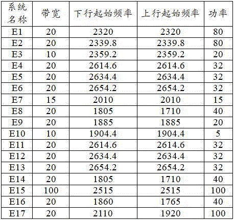
therefore, the interference tracing is performed by adopting the method for determining the intermodulation product interference provided by the embodiment, the calculation time is reduced by multiple times, and the determination consumption time is effectively shortened.
Referring to fig. 7, fig. 7 is a block diagram of an intermodulation product interference determination apparatus according to an embodiment of the present invention, and as shown in fig. 7, an intermodulation product interference determination apparatus 700 includes:
an obtaining module 701, configured to obtain a signal source power, a first frequency range of an uplink frequency, a downlink central frequency, a frequency bandwidth corresponding to the downlink central frequency, and a coefficient matrix of an n-order intermodulation product, where the n-order intermodulation product is an intermodulation product generated by n signal sources in the L base stations through interaction, and the coefficient matrix is used to represent a calculation coefficient of the signal source corresponding to the n-order intermodulation product, where L is a positive integer greater than 2, n is a positive integer 2, 3, or 5, and n is smaller than L, and each row in the coefficient matrix is used to represent coefficients of n signal sources corresponding to one n-order intermodulation product;
a first generating module 702, configured to generate an initial center frequency matrix based on a downlink center frequency of each base station, where each column of the initial center frequency matrix is used to represent downlink center frequencies of n signal sources corresponding to one n-order intermodulation product;
a second generating module 703, configured to multiply the initial center frequency matrix and the coefficient matrix to generate a target center frequency matrix, where the target center frequency matrix is used to characterize frequencies of n-order intermodulation products generated by n signal sources in the L base stations;
a third generating module 704, configured to generate a target bandwidth matrix based on the frequency bandwidth of each base station and the coefficient matrix, where the target bandwidth matrix is used to characterize the frequency bandwidths of n-order intermodulation products generated by n signal sources in the L base stations, and the positions of the target bandwidth matrix and the target center frequency matrix in the same row and column correspond to the same signal source;
a first calculating module 705 for calculating a second frequency range of the n-order intermodulation products based on the target center frequency matrix and the target bandwidth matrix;
a second calculating module 706, configured to calculate, based on the first frequency range, the second frequency range and the signal source power, an interference noise value of the n-order intermodulation product, where there is an overlapping area between the second frequency range and the first frequency range, and the interference noise value is used to characterize interference of the n-order intermodulation product on L signal sources;
a first processing module 707, configured to, if the interference noise value corresponding to the n-th order intermodulation product is greater than a set threshold, determine coefficients of n signal sources of the n-th order intermodulation product based on the number of rows of the n-th order intermodulation product in the target center frequency matrix or the target bandwidth matrix and the coefficient matrix;
a second processing module 708, configured to determine downlink center frequencies of n signal sources of the n-th order intermodulation products based on the number of columns of the n-th order intermodulation products in the target center frequency matrix or the target bandwidth matrix and the initial center frequency matrix.
Optionally, the third generating module 704 includes:
the first processing submodule is used for determining an initial bandwidth matrix based on the frequency bandwidth of each base station and the initial central frequency matrix, the positions of the initial bandwidth matrix and the initial central frequency matrix in the same row and column correspond to the same signal source, and the initial bandwidth matrix is used for representing the frequency bandwidth of each base station in different n signal source combinations;
and the second processing submodule is used for multiplying the absolute value of the coefficient matrix and the initial bandwidth matrix to obtain a target bandwidth matrix of the n-order intermodulation product.
Optionally, the second calculating module 706 includes:
a first calculation submodule, configured to calculate a target intensity ratio based on the overlap region and the second frequency range, where the target intensity ratio is used to characterize a signal power intensity ratio between the overlap region and the n-order intermodulation product;
the second calculation submodule is used for calculating the power intensity of the n-order intermodulation product based on the coefficient matrix and the signal source power;
a third calculation submodule for setting a product of the target intensity ratio and the power intensity of the n-order intermodulation products as the interference noise value.
Optionally, the first computing submodule includes:
a first calculating unit, configured to calculate, based on the overlapping area and the second frequency range, a first ratio of the overlapping area in a first area of the second frequency range and a second ratio of the overlapping area in a second area of the second frequency range, where the first area and the second area are areas of the second frequency range, the first area is located on two sides of the second area, and the first area is larger than the second area;
a second calculating unit, configured to set a sum of a product of the first ratio and a first power ratio of the first area and a product of the second ratio and a second power ratio of the second area as the target intensity ratio, where the first power ratio is the same as the second power ratio.
Optionally, the second computing submodule includes:
an obtaining unit, configured to obtain an intermodulation suppression degree and a rated input carrier power of a device under test that receives L signal sources, where the device under test is used to characterize a device that receives a signal source of each base station in the L base stations;
a third calculating unit, configured to bring the intermodulation suppression degree, the rated input carrier power, the coefficient matrix, and the signal source power into a preset formula, to obtain the power strength of the n-order intermodulation product, where the preset formula includes a first formula corresponding to the case where n is 2 or 3, and a second formula corresponding to the case where n is 5, where the power strength of the n-order intermodulation product is calculated through the first formula as follows:

P RIM for the power strength, RIM is the intermodulation suppression degree, P 1 For said nominal input carrier power, O 1 To O n Is the coefficient, P f1 To P fn Is the signal source power;
the power strength of the n-th order intermodulation product is calculated by the second equation as follows:

and K is a constant.
Optionally, the first calculating module 705 includes:
a fourth calculation submodule, configured to calculate a first product value of the target bandwidth matrix and the first weighting value, and set a difference between the target center frequency matrix and the first product value as a minimum value of the second frequency range;
a fifth calculation sub-module, configured to calculate a second product value of the target bandwidth matrix and a second weighting value, and set a sum of the target center frequency matrix and the second product value as a maximum value of the second frequency range.
The intermodulation product interference determination apparatus provided in the embodiment of the present invention is capable of implementing each process of each embodiment of the intermodulation product interference determination method, and has one-to-one correspondence of technical features, and can achieve the same technical effect, and is not described here again to avoid repetition.
It should be noted that the intermodulation product interference determination apparatus in the embodiment of the present invention may be an apparatus, or may be a component, an integrated circuit, or a chip in an electronic device.
An embodiment of the present invention further provides an electronic device, referring to fig. 8, where fig. 8 is a schematic structural diagram of an electronic device according to an embodiment of the present invention, and the electronic device includes a memory 801, a processor 802, and a program or an instruction stored in the memory 801 and run on the memory 802, and when the program or the instruction is executed by the processor 802, any step in the method embodiment corresponding to fig. 1 may be implemented and the same beneficial effect may be achieved, which is not described herein again.
The processor 802 may be a CPU, ASIC, FPGA, or GPU, among others.
Those skilled in the art will appreciate that all or part of the steps of the method according to the above embodiments may be implemented by hardware related to program instructions, and the program may be stored in a readable medium.
An embodiment of the present invention further provides a readable storage medium, where a computer program is stored on the readable storage medium, and when the computer program is executed by a processor, any step in the method embodiment corresponding to fig. 1 may be implemented, and the same technical effect may be achieved, and in order to avoid repetition, details are not repeated here. The storage medium may be a Read-Only Memory (ROM), a Random Access Memory (RAM), a magnetic disk or an optical disk.
The terms "first," "second," and the like in the embodiments of the present invention are used for distinguishing between similar elements and not necessarily for describing a particular sequential or chronological order. Furthermore, the terms "comprises," "comprising," and "having," and any variations thereof, are intended to cover a non-exclusive inclusion, such that a process, method, system, article, or apparatus that comprises a list of steps or elements is not necessarily limited to those steps or elements expressly listed, but may include other steps or elements not expressly listed or inherent to such process, method, article, or apparatus. Further, as used herein, "and/or" means at least one of the connected objects, e.g., a and/or B and/or C, means 7 cases including a alone, B alone, C alone, and both a and B present, B and C present, a and C present, and a, B, and C present.
It should be noted that, in this document, the terms "comprises," "comprising," or any other variation thereof, are intended to cover a non-exclusive inclusion, such that a process, method, article, or apparatus that comprises a list of elements does not include only those elements but may include other elements not expressly listed or inherent to such process, method, article, or apparatus. Without further limitation, an element defined by the phrases "comprising a component of' 8230; \8230;" does not exclude the presence of another like element in a process, method, article, or apparatus that comprises the element.
Through the above description of the embodiments, those skilled in the art will clearly understand that the method of the above embodiments can be implemented by software plus a necessary general hardware platform, and certainly can also be implemented by hardware, but in many cases, the former is a better implementation manner. Based on such understanding, the technical solution of the present application may be substantially or partially embodied in the form of a software product, which is stored in a storage medium (e.g. ROM/RAM, magnetic disk, optical disk) and includes instructions for enabling a terminal (e.g. a mobile phone, a computer, a server, an air conditioner, or a second terminal device) to execute the method of the embodiments of the present application.
While the present embodiments have been described with reference to the accompanying drawings, it is to be understood that the invention is not limited to the precise embodiments described above, which are meant to be illustrative and not restrictive, and that various changes may be made therein by those skilled in the art without departing from the spirit and scope of the invention as defined by the appended claims.
Claims (10)


Priority Applications (1)
| Application Number | Priority Date | Filing Date | Title |
|---|---|---|---|
| CN202310244979.6A CN115967947B (en) | 2023-03-15 | 2023-03-15 | Intermodulation product interference determination method, device, electronic equipment and readable storage medium |
Applications Claiming Priority (1)
| Application Number | Priority Date | Filing Date | Title |
|---|---|---|---|
| CN202310244979.6A CN115967947B (en) | 2023-03-15 | 2023-03-15 | Intermodulation product interference determination method, device, electronic equipment and readable storage medium |
Publications (2)
| Publication Number | Publication Date |
|---|---|
| CN115967947A true CN115967947A (en) | 2023-04-14 |
| CN115967947B CN115967947B (en) | 2023-05-09 |
Family
ID=85890478
Family Applications (1)
| Application Number | Title | Priority Date | Filing Date |
|---|---|---|---|
| CN202310244979.6A Active CN115967947B (en) | 2023-03-15 | 2023-03-15 | Intermodulation product interference determination method, device, electronic equipment and readable storage medium |
Country Status (1)
| Country | Link |
|---|---|
| CN (1) | CN115967947B (en) |
Citations (8)
| Publication number | Priority date | Publication date | Assignee | Title |
|---|---|---|---|---|
| CN205356357U (en) * | 2016-01-20 | 2016-06-29 | 南京迈科拓通讯有限公司 | Multifrequency section passive signal combination intermodulation interference's test system |
| CN105959066A (en) * | 2016-04-27 | 2016-09-21 | 浙江大学 | Multiple passive intermodulation generation points positioning method based on matrix pencil method |
| US20190052294A1 (en) * | 2017-08-09 | 2019-02-14 | Isco International, Llc | Method and apparatus for detecting and analyzing passive intermodulation interference in a communication system |
| CN111988790A (en) * | 2020-08-28 | 2020-11-24 | 中国铁塔股份有限公司 | Intermodulation interference processing method and device, electronic equipment and readable storage medium |
| CN113141653A (en) * | 2020-01-17 | 2021-07-20 | 上海华为技术有限公司 | Passive intermodulation interference suppression method and related equipment |
| WO2022037188A1 (en) * | 2020-08-20 | 2022-02-24 | 华为技术有限公司 | Passive inter-modulation source positioning method and apparatus |
| US20220158673A1 (en) * | 2019-03-20 | 2022-05-19 | Telefonaktiebolaget Lm Ericsson (Publ) | Method and Control Device for Mitigating Interference |
| CN115694768A (en) * | 2022-11-02 | 2023-02-03 | 中国铁塔股份有限公司 | Intermodulation interference analysis method, device, electronic equipment and readable storage medium |
-
2023
- 2023-03-15 CN CN202310244979.6A patent/CN115967947B/en active Active
Patent Citations (8)
| Publication number | Priority date | Publication date | Assignee | Title |
|---|---|---|---|---|
| CN205356357U (en) * | 2016-01-20 | 2016-06-29 | 南京迈科拓通讯有限公司 | Multifrequency section passive signal combination intermodulation interference's test system |
| CN105959066A (en) * | 2016-04-27 | 2016-09-21 | 浙江大学 | Multiple passive intermodulation generation points positioning method based on matrix pencil method |
| US20190052294A1 (en) * | 2017-08-09 | 2019-02-14 | Isco International, Llc | Method and apparatus for detecting and analyzing passive intermodulation interference in a communication system |
| US20220158673A1 (en) * | 2019-03-20 | 2022-05-19 | Telefonaktiebolaget Lm Ericsson (Publ) | Method and Control Device for Mitigating Interference |
| CN113141653A (en) * | 2020-01-17 | 2021-07-20 | 上海华为技术有限公司 | Passive intermodulation interference suppression method and related equipment |
| WO2022037188A1 (en) * | 2020-08-20 | 2022-02-24 | 华为技术有限公司 | Passive inter-modulation source positioning method and apparatus |
| CN111988790A (en) * | 2020-08-28 | 2020-11-24 | 中国铁塔股份有限公司 | Intermodulation interference processing method and device, electronic equipment and readable storage medium |
| CN115694768A (en) * | 2022-11-02 | 2023-02-03 | 中国铁塔股份有限公司 | Intermodulation interference analysis method, device, electronic equipment and readable storage medium |
Non-Patent Citations (1)
| Title |
|---|
| 夏天 等: "5G室内分布系统互调干扰解决方案", 电子技术应用 * |
Also Published As
| Publication number | Publication date |
|---|---|
| CN115967947B (en) | 2023-05-09 |
Similar Documents
| Publication | Publication Date | Title |
|---|---|---|
| KR102436859B1 (en) | Method and system for testing wireless performance of wireless terminals | |
| US10256923B2 (en) | Method and device for generating MIMO test signal | |
| CN113688507B (en) | Optimal configuration and type selection method for amplifier of radio frequency link of superheterodyne receiver | |
| CN112350756B (en) | Method and device for optimizing weight parameters of antenna and electronic equipment | |
| CN108632856B (en) | Processing method for determining target neighbor cell and server | |
| Parshin et al. | Investigation of efficient receiving of ultra low power signal for IoT application | |
| Testolina et al. | Scalable and accurate modeling of the millimeter wave channel | |
| CN115967947A (en) | Intermodulation product interference determination method and device, electronic equipment and readable storage medium | |
| CN111880201A (en) | Beidou terminal testing system, testing method and testing device | |
| Shinakov | Power spectral density of interference caused by nonlinear distortions in devices with amplitude-phase conversion | |
| Tellambura | Cochannel interference computation for arbitrary Nakagami fading | |
| US11140636B1 (en) | Roaming method based on MESH WIFI, electronic device and computer program product | |
| CN105430682A (en) | Mobile communication signal interference protection evaluation method and system | |
| US20190199453A1 (en) | Method and radio network node for determining total radiated power from a plurality of antennas | |
| JP7742487B2 (en) | Reducing interference from downlink attackers | |
| JP6933106B2 (en) | Distortion canceling device and distortion canceling method | |
| US9692465B1 (en) | Aggregate interference model and use thereof to evaluate performance of a receiver | |
| Biondi et al. | Electromagnetic compatibility aware design and testing of intermodulation distortion under multiple co-located sources illumination | |
| CA3084614C (en) | System and method for mitigating broadband interference | |
| Biondi et al. | Multi-tone EMC testing strategy for RF-devices | |
| Kassianides et al. | Dynamic model of tropospheric scintillation on earth-space paths | |
| Sinkevich | Worst-case models of RF front-end nonlinearity for discrete nonlinear analysis of electromagnetic compatibility | |
| US12385961B2 (en) | Method for total isotropic sensitivity testing of a user equipment | |
| Fu et al. | BER analysis of coherent FSO systems with SC receive diversity over correlated turbulence channels | |
| Li et al. | A Novel Method for Tailoring the Electromagnetic Radiation Emission Limits of Equipment in Complex System |
Legal Events
| Date | Code | Title | Description |
|---|---|---|---|
| PB01 | Publication | ||
| PB01 | Publication | ||
| SE01 | Entry into force of request for substantive examination | ||
| SE01 | Entry into force of request for substantive examination | ||
| GR01 | Patent grant | ||
| GR01 | Patent grant |