[go: up one dir, main page]

CN115919504B - Split type single embedded branch tectorial membrane support - Google Patents

Split type single embedded branch tectorial membrane support Download PDF

Info

Publication number
CN115919504B
CN115919504B CN202310155246.5A CN202310155246A CN115919504B CN 115919504 B CN115919504 B CN 115919504B CN 202310155246 A CN202310155246 A CN 202310155246A CN 115919504 B CN115919504 B CN 115919504B
Authority
CN
China
Prior art keywords
stent
branch
support
framework
embedded
Prior art date
Legal status (The legal status is an assumption and is not a legal conclusion. Google has not performed a legal analysis and makes no representation as to the accuracy of the status listed.)
Active
Application number
CN202310155246.5A
Other languages
Chinese (zh)
Other versions
CN115919504A (en
Inventor
王永胜
尹玉杨
吴雅莎
肖添
Current Assignee (The listed assignees may be inaccurate. Google has not performed a legal analysis and makes no representation or warranty as to the accuracy of the list.)
Hangzhou Wei Qiang Medical Technology Co ltd
Original Assignee
Hangzhou Wei Qiang Medical Technology Co ltd
Priority date (The priority date is an assumption and is not a legal conclusion. Google has not performed a legal analysis and makes no representation as to the accuracy of the date listed.)
Filing date
Publication date
Application filed by Hangzhou Wei Qiang Medical Technology Co ltd filed Critical Hangzhou Wei Qiang Medical Technology Co ltd
Priority to CN202310155246.5A priority Critical patent/CN115919504B/en
Publication of CN115919504A publication Critical patent/CN115919504A/en
Application granted granted Critical
Publication of CN115919504B publication Critical patent/CN115919504B/en
Active legal-status Critical Current
Anticipated expiration legal-status Critical

Links

Images

Landscapes

  • Prostheses (AREA)

Abstract

本申请涉及一种分体式单内嵌分支覆膜支架,其包括设有至少一开窗结构的主体支架;内嵌支架的一端密封固定于开窗结构,以使开窗结构通过内嵌支架与主体支架的连通腔连通;分支支架通过开窗结构可拆卸插接于内嵌支架内;分支支架包括分支覆膜以及固定于分支覆膜的分支骨架组件,沿分支支架的径向,分支覆膜包括第一层膜和第二层膜,第一层膜位于分支支架的连接腔的内侧,第二层膜位于分支支架的外侧,分支骨架组件固定于第一层膜和第二层膜之间,分支覆膜的近端和远端分别一体成形有翻折段,翻折段固定于分支覆膜的内周壁。本申请具有减少心动周期内分支支架对LSA远端血管壁的损伤刺激,提高分支动脉远期通畅率的效果。

Figure 202310155246

The present application relates to a split-type single embedded branch covered stent, which includes a main frame with at least one fenestration structure; one end of the embedded stent is sealed and fixed to the fenestration structure, so that the fenestration structure passes through the embedded stent and the fenestration structure. The connecting cavity of the main stent is connected; the branch stent is detachably inserted into the embedded stent through the fenestration structure; the branch stent includes the branch film and the branch skeleton assembly fixed on the branch film. Along the radial direction of the branch stent, the branch film Including a first layer of membrane and a second layer of membrane, the first layer of membrane is located inside the connecting cavity of the branch stent, the second layer of membrane is located outside the branch stent, and the branch skeleton assembly is fixed between the first layer of membrane and the second layer of membrane , the proximal end and the far end of the branch coating are respectively integrally formed with folded sections, and the folded sections are fixed to the inner peripheral wall of the branch coating. The application has the effect of reducing the damage and stimulation of the branch stent to the LSA distal vessel wall in the cardiac cycle, and improving the long-term patency rate of the branch artery.

Figure 202310155246

Description

分体式单内嵌分支覆膜支架Split single embedded branch covered stent

技术领域technical field

本申请涉及医疗器械的领域,尤其是涉及一种分体式单内嵌分支覆膜支架。The present application relates to the field of medical devices, in particular to a split-type single-embedded branch covered stent.

背景技术Background technique

随着腔内技术的提高及材料科学的进步,腔内修复术(Thoracic EndovascularAortic Artery Repair, TEVAR)已经成为B型主动脉夹层的首选治疗方式,但对于破口或血肿靠近分支动脉(例如左锁骨动脉(LeftSubclavian Artery, LSA))的病变由于近端锚定区不足或不健康,常规TEVAR需封堵左锁骨动脉以延长近端锚定区,但术后可能出现左上肢缺血、锁骨下动脉窃血综合征、椎动脉型脑缺血等并发症,并增加截瘫的风险,因此在进行TEVAR 手术治疗Stanford B型夹层时,保留或重建左锁骨动脉非常重要。With the improvement of endovascular technology and advances in material science, Thoracic Endovascular Aortic Artery Repair (TEVAR) has become the first choice for the treatment of type B aortic dissection. Artery (Left Subclavian Artery, LSA)) lesions due to insufficient or unhealthy proximal anchoring area, conventional TEVAR needs to occlude the left clavicle artery to prolong the proximal anchoring area, but left upper limb ischemia, subclavian artery stealing may occur after surgery Therefore, it is very important to preserve or reconstruct the left clavicle artery when performing TEVAR surgery for Stanford type B dissection.

左锁骨动脉重建的常用手术方式有杂交手术、平行支架技术、开窗技术和分支支架技术等。杂交手术效果确切,但相比全腔内手术仍有创伤大、手术时间长的缺点。平行支架技术相对简单易于操作,但由于两个支架间存在沟槽(gutter),使得I型内漏出现的几率增高,另外支架间和支架与主动脉壁间的相互作用力使得逆撕夹层和平行支架闭塞的风险增高。开窗技术主要是在支架的人工血管膜上预留、术前根据具体情况设计侧孔或者原位开窗,支架释放后通过侧孔保留分支动脉血供,缺点是定位不准确,技术难度高,存在失败的风险,改造支架过程中有增加感染的几率,或者有影响LSA支架远期通畅率、主体支架结构稳定和/或使用寿命的风险。分支支架技术更加符合生理解剖,在降低I型内漏风险的同时也降低了III型内漏风险,对破口位于LSA的病变也能有效隔绝,未来有望成为重建LSA的首选方式。Common surgical methods for left clavicle artery reconstruction include hybrid surgery, parallel stent technique, fenestration technique, and branch stent technique. Hybrid surgery is effective, but compared with total endovascular surgery, it still has the disadvantages of large trauma and long operation time. Parallel stent technology is relatively simple and easy to operate, but because there is a gutter between the two stents, the probability of type I endoleak increases, and the interaction force between the stents and between the stent and the aortic wall makes reverse tearing of the dissection and There is an increased risk of parallel stent occlusion. The fenestration technique is mainly to reserve on the artificial vascular membrane of the stent, design a side hole or in-situ fenestration according to the specific situation before the operation, and reserve the blood supply of the branch arteries through the side hole after the stent is released. The disadvantage is that the positioning is not accurate and the technical difficulty is high. , there is a risk of failure, an increase in the chance of infection during the reconstruction of the stent, or a risk of affecting the long-term patency rate of the LSA stent, the structural stability of the main stent and/or the service life. The branch stent technology is more in line with the physiological anatomy. While reducing the risk of type I endoleak, it also reduces the risk of type III endoleak. It can also effectively isolate lesions with breaches located in LSA. It is expected to become the first choice for reconstructing LSA in the future.

分支支架技术中提供了一种一体化分支型主动脉覆膜支架的技术以治疗Stanford B型夹层患者,其利用相应的介入器械将覆膜支架径向压缩后输送至病变位置后释放出来,以使覆膜支架回复至预定形态,从而将人体血管的夹层破口或扩大的腔体隔开来,重塑血管真腔,使血流恢复正确的流向,进而达到治疗效果。为了保证分支动脉的血供,通常通过分支支架连接分支动脉和覆膜支架,即,将分支支架和覆膜支架一体设置,并将分支支架释放于分支动脉内,从而起到保证分支动脉血供的效果。然而,分支支架在拉入分支动脉内时会对动脉内壁造成损伤。Branch stent technology provides an integrated branched aortic stent-graft technology to treat patients with Stanford type B dissection. It uses corresponding interventional instruments to radially compress the stent-graft and deliver it to the lesion position to release it. Restore the stent graft to the predetermined shape, thereby separating the dissection breach or enlarged cavity of the human blood vessel, reshaping the true lumen of the blood vessel, and restoring the blood flow to the correct direction, thereby achieving the therapeutic effect. In order to ensure the blood supply of the branch arteries, the branch arteries and the stent graft are usually connected by a branch stent, that is, the branch stent and the stent graft are integrated, and the branch stent is released in the branch artery, thereby ensuring the blood supply of the branch artery. Effect. However, branch stents can cause damage to the inner wall of the artery when pulled into the branch artery.

发明内容Contents of the invention

为了改善现有的覆膜支架的分支支架在拉入分支动脉内时会对动脉内壁造成损失的问题,本申请提供一种分体式单内嵌分支覆膜支架。In order to improve the problem that the branch stent of the existing covered stent will cause damage to the inner wall of the artery when it is pulled into the branch artery, the present application provides a split-type single-embedded branch covered stent.

本申请提供一种分体式单内嵌分支覆膜支架,包括主体支架,所述主体支架为两端开口的管状结构,所述主体支架围合成用于和目标血管连通的连通腔,所述主体支架设有至少一开窗结构;The application provides a split-type single embedded branch covered stent, including a main body stent, the main body stent is a tubular structure with openings at both ends, the main body stent encloses a communication cavity for communicating with the target blood vessel, the main body The bracket is provided with at least one window structure;

内嵌支架,所述内嵌支架为两端开口的管状结构,所述内嵌支架的一端密封固定于所述开窗结构,以使所述开窗结构通过所述内嵌支架与所述主体支架的所述连通腔连通;及An embedded bracket, the embedded bracket is a tubular structure with openings at both ends, and one end of the embedded bracket is sealed and fixed to the window structure, so that the window structure passes through the embedded bracket and the main body The communication cavity of the stent communicates; and

分支支架,所述分支支架为两端开口的管状结构,所述分支支架围合成用于和分支动脉连通的连接腔,所述分支支架通过所述开窗结构可拆卸插接于所述内嵌支架内,以使所述分支支架的所述连接腔与所述连通腔连通;A branch stent, the branch stent is a tubular structure with openings at both ends, the branch stent encloses a connecting cavity for communicating with the branch artery, and the branch stent is detachably plugged into the embedded In the stent, the connection cavity of the branch stent communicates with the communication cavity;

所述分支支架包括分支覆膜以及固定于所述分支覆膜的分支骨架组件,沿所述分支支架的径向,所述分支覆膜包括第一层膜和第二层膜,所述第一层膜位于所述分支支架的所述连接腔的内侧,所述第二层膜位于所述分支支架的外侧,所述分支骨架组件固定于所述第一层膜和所述第二层膜之间,所述分支覆膜的近端和远端分别一体成形有翻折段,所述翻折段固定于所述分支覆膜的内周壁。The branch stent includes a branch film and a branch skeleton assembly fixed to the branch film. Along the radial direction of the branch stent, the branch film includes a first layer of film and a second layer of film. The first A layer of membrane is located inside the connecting cavity of the branch stent, the second layer of membrane is located outside the branch stent, and the branch skeleton assembly is fixed between the first layer of membrane and the second layer of membrane In between, the proximal end and the distal end of the branch coating are respectively integrally formed with folded sections, and the folded sections are fixed to the inner peripheral wall of the branch coating.

在其他一些实施方式中,所述主体支架包括管状覆膜、裸支架及多个支撑骨架,所述裸支架和所述支撑骨架均呈环状结构,所述裸支架固定于所述管状覆膜的近端,多个所述支撑骨架位于所述裸支架的远端侧,多个所述支撑骨架沿所述管状覆膜的轴向依次排列固定;所述裸支架和所述支撑骨架均包括多个呈夹角依次相连的支撑杆,沿所述主体支架的周向上,相邻的两个所述夹角分别为波峰和波谷,所述波峰相比所述波谷更靠近所述主体支架的近端;至少部分所述支撑骨架的所述波峰、所述波谷和所述支撑杆均贴合固定于所述管状覆膜的周壁,至少部分所述支撑骨架的至少部分所述波峰与所述管状覆膜之间具有间隙且能够和所述管状覆膜分离从而形成自由区,所述自由区的轴向长度至少为2.5-4mm。In some other embodiments, the main body stent includes a tubular membrane, a bare stent, and a plurality of supporting skeletons, both the bare stent and the supporting framework are in a ring structure, and the bare stent is fixed on the tubular membrane A plurality of the support skeletons are located at the distal end side of the bare stent, and a plurality of the support skeletons are arranged and fixed in sequence along the axial direction of the tubular covering; the bare stent and the support skeleton both include A plurality of supporting rods connected successively at included angles, along the circumferential direction of the main body bracket, two adjacent included angles are respectively crests and troughs, and the crests are closer to the center of the main body bracket than the troughs Proximal end: at least part of the crests, troughs and the support rods of the supporting frame are fitted and fixed on the peripheral wall of the tubular covering, at least part of the crests of the supporting frame are in contact with the The tubular coverings have gaps therebetween and are separable from said tubular coverings to form free zones, said free zones having an axial length of at least 2.5-4 mm.

在其他一些实施方式中,多个所述支撑骨架包括沿所述管状覆膜的近端至远端依次排列的贴壁骨架、束径骨架、辅助骨架及远端骨架,所述贴壁骨架和所述束径骨架均位于所述开窗结构的近端侧,所述辅助骨架及所述远端骨架均位于所述开窗结构的远端侧;所述裸支架的所述波谷固定于所述管状覆膜,所述裸支架的所述波峰和所述裸支架的所述支撑杆至少局部延伸出所述管状覆膜的近端;所述贴壁骨架上的各支撑杆的轴向长度均相同;所述束径骨架设有多个,至少一所述束径骨架上的各支撑杆的轴向长度均相同;所述远端骨架上的各支撑杆的轴向长度均相同;In some other embodiments, the plurality of supporting skeletons include an adherent skeleton, a bundle diameter skeleton, an auxiliary skeleton and a distal skeleton arranged in sequence from the proximal end to the distal end of the tubular membrane, and the adherent skeleton and The beam diameter skeletons are all located on the proximal side of the fenestration structure, the auxiliary skeleton and the distal skeleton are both located on the distal side of the fenestration structure; the troughs of the bare stent are fixed on the The tubular covering, the crest of the bare stent and the struts of the bare stent at least partially extend beyond the proximal end of the tubular covering; the axial length of each strut on the adherent skeleton are all the same; there are multiple beam diameter skeletons, and the axial lengths of the supporting rods on at least one of the beam diameter skeletons are the same; the axial lengths of the supporting rods on the distal end skeleton are the same;

所述辅助骨架设置有至少两个,相邻两个所述辅助骨架的所述波谷在轴向上相对,相邻两个所述辅助骨架的所述波峰在轴向上相对;沿所述主体支架的周向上,所述辅助骨架上相邻的两个所述波峰中包括高波和低波,所述高波相比所述低波更靠近所述主体支架的近端;所述辅助骨架上的所述波峰中,所述高波和所述低波沿所述主体支架的周向交替设置。There are at least two auxiliary frames, the troughs of two adjacent auxiliary frames are axially opposite, and the peaks of two adjacent auxiliary frames are axially opposite; along the main body In the circumferential direction of the bracket, the two adjacent peaks on the auxiliary frame include high waves and low waves, and the high waves are closer to the proximal end of the main body bracket than the low waves; Among the peaks, the high waves and the low waves are arranged alternately along the circumferential direction of the main body bracket.

在其他一些实施方式中,所述裸支架的所述波谷通过缝合线加密缝合固定有多个缝合线圈以将所述裸支架的所述波谷固定于所述管状覆膜,所述支撑杆通过缝合线缝合固定有至少一个缝合线圈以将所述裸支架的所述支撑杆固定于所述管状覆膜,且所述裸支架的所述支撑杆上的所述缝合线圈与所述裸支架的所述波谷上的所述缝合线圈紧密相邻;所述裸支架的所述波谷和所述支撑杆通过所述缝合线圈固定于所述管状覆膜的轴向长度形成锚定区,所述锚定区的轴向长度至少为3-5mm,所述锚定区的轴向长度为所述裸支架与所述贴壁骨架在轴向上的重合长度。In some other embodiments, the trough of the bare stent is fixed with a plurality of suture loops by dense sutures to fix the trough of the bare stent to the tubular graft, and the support rod is fixed by suturing. At least one suture coil is fixed by thread suture to fix the support rod of the bare stent to the tubular graft, and the suture coil on the support rod of the bare stent is connected to the The suture coils on the troughs are closely adjacent; the troughs of the bare stent and the struts are fixed to the axial length of the tubular graft by the suture coils to form an anchoring zone, and the anchoring The axial length of the region is at least 3-5 mm, and the axial length of the anchoring region is the overlapping length of the bare stent and the adherent framework in the axial direction.

在其他一些实施方式中,多个所述支撑骨架还包括至少一第一加强骨架,至少一所述第一加强骨架位于所述开窗结构的远端侧;所述束径骨架还包括至少一第二加强骨架,至少一所述第二加强骨架位于至少一所述第二全固定骨架的远端侧,所述第一加强骨架和所述第二加强骨架在轴向上相邻设置,所述第一加强骨架和所述第二加强骨架分别位于所述开窗结构轴向上的两侧;至少一所述第一加强骨架上的所述支撑杆的轴向长度相同,至少一所述第二加强骨架上的所述支撑杆的轴向长度相同,至少一所述第一加强骨架上的所述波峰、所述波谷和所述支撑杆均贴合固定于所述管状覆膜的周壁,所述第一加强骨架上的所述波谷和所述第二加强骨架上的所述波峰在轴向上相对。In some other embodiments, the plurality of supporting frames further include at least one first reinforcing frame, and at least one of the first reinforcing frames is located at the distal side of the fenestration structure; the beam diameter frame also includes at least one The second reinforcing frame, at least one second reinforcing frame is located on the distal side of at least one second full fixed frame, the first reinforcing frame and the second reinforcing frame are arranged adjacent to each other in the axial direction, so The first reinforcing frame and the second reinforcing frame are respectively located on both sides of the window structure in the axial direction; at least one of the supporting rods on the first reinforcing frame has the same axial length, and at least one of the The axial lengths of the supporting rods on the second reinforcing frame are the same, and the peaks, the troughs and the supporting rods on at least one of the first reinforcing frames are all attached and fixed to the peripheral wall of the tubular coating , the trough on the first reinforcing skeleton is axially opposite to the crest on the second reinforcing skeleton.

在其他一些实施方式中,所述柔性束径构件为一环状结构,所述束径构件的环上任意至少两点固定于所述主体支架以形成两个固定位点,进而使所述柔性束径构件形成至少两个柔性环;或者,所述柔性束径构件包括至少两个柔性环,所述柔性环长度方向的一端固定于所述管状覆膜和所述支撑骨架的至少一者以形成固定位点;In some other embodiments, the flexible beam diameter member is a ring structure, and any at least two points on the ring of the beam diameter member are fixed to the main body bracket to form two fixing points, so that the flexible The bundle diameter member forms at least two flexible rings; alternatively, the flexible bundle diameter member includes at least two flexible rings, and one end of the flexible ring in the length direction is fixed to at least one of the tubular membrane and the supporting frame to Form a fixed site;

沿所述主体支架的周向,两个所述柔性环远离所述固定位点的一端能够相互重合以形成供束径导丝穿设的线环,所述柔性环的长度方向能够沿所述主体支架的周向排布,至少两个所述柔性环的长度方向能够围抱所述主体支架的周向以使所述主体支架能够径向压缩。Along the circumferential direction of the main body bracket, the ends of the two flexible rings away from the fixing point can overlap each other to form a wire loop for the bundle diameter guide wire to pass through, and the length direction of the flexible ring can be along the The circumferential arrangement of the main body bracket, the length direction of at least two flexible rings can surround the circumferential direction of the main body bracket so that the main body bracket can be radially compressed.

在其他一些实施方式中,所述固定位为固定套,所述固定套将所述连接骨固定于每一所述第一波形环对应的所述分支杆上;或者,所述至少部分固定位由每一所述第一波形环上所述连接骨所在的所述分支杆螺旋缠绕于所述连接骨而形成。In some other embodiments, the fixing position is a fixing sleeve, and the fixing sleeve fixes the connecting bone on the branch rod corresponding to each of the first wave-shaped rings; or, the at least part of the fixing position Each of the first wave-shaped rings is formed by helically winding the branch rod where the connecting bone is located on the connecting bone.

本申请提供的分体式单内嵌分支覆膜支架,分支支架通过开窗结构插接于内嵌支架内,以使分支支架与连通腔连通,从而将流经连通腔内的血流引入分支支架,重建分支动脉,分支支架与主体支架的可拆卸插接配合,能够减少心动周期内分支支架对 LSA 远端血管壁的损伤刺激,进而保证分支动脉远期通畅率。分支支架的结构设计对分支动脉的远期通畅率有重大影响,分支覆膜为两层膜状物,且分支骨架组件位于两层膜状物之间,进一步能够减少心动周期内分支支架对 LSA 远端血管壁的损伤刺激。分支支架径向压缩于介入器械的过程中,或者分支支架在脱离介入器械以释放于分支动脉的过程中,分支支架与介入器械之间的摩擦力、目标血管和分支动脉自身的脉动、不恰当地主体支架和分支支架释放、定位,都对两层膜状物有不同程度的分离考验,即,两层膜状物具有至少部分彼此分离的风险,导致分支支架具有闭塞的风险,影响分支支架的远期通畅率。至少两段翻折段的设置,有利于改善第一层膜和第二层膜的近端和远端受到高流量血流的冲击、分支支架压缩和释放过程中与介入器械之间的摩擦力、目标血管与分支动脉自身的脉动对分支支架的冲击离或者不恰当的操作而至少部分分离的问题,降低分支支架发生闭塞的风险,提高分支支架的远期通畅率。In the split-type single embedded branch covered stent provided by the present application, the branched stent is inserted into the embedded stent through the fenestrated structure, so that the branched stent communicates with the communicating cavity, so that the blood flow flowing through the communicating cavity is introduced into the branched stent , to reconstruct branch arteries, the detachable plug-in cooperation between the branch stent and the main body stent can reduce the damage and stimulation of the branch stent to the LSA distal vessel wall during the cardiac cycle, thereby ensuring the long-term patency of the branch artery. The structural design of the branch stent has a significant impact on the long-term patency of the branch artery. The covering of the branch is two layers of membrane, and the branch skeleton component is located between the two layers of membrane, which can further reduce the impact of the branch stent on the LSA during the cardiac cycle. Injury stimulation of the distal vessel wall. During the process of radial compression of the branch stent in the interventional device, or in the process of releasing the branch stent from the interventional device to the branch artery, the friction between the branch stent and the interventional device, the pulsation of the target vessel and the branch artery itself, inappropriate The release and positioning of the main body stent and the branch stent have different degrees of separation tests on the two layers of membranous material, that is, the two layers of membranous material have the risk of being at least partially separated from each other, resulting in the risk of occlusion of the branch stent and affecting the branch stent. long-term patency. The setting of at least two turning sections is beneficial to improve the friction force between the proximal end and the distal end of the first layer of film and the second layer of film being impacted by high-flow blood flow, and the friction between the branch stent and the interventional instrument during the compression and release process 1. The impact of the target blood vessel and the branch artery's own pulsation on the branch stent or the problem of at least partial separation due to inappropriate operation reduces the risk of occlusion of the branch stent and improves the long-term patency rate of the branch stent.

附图说明Description of drawings

图1为分体式单内嵌分支覆膜支架的结构示意图。Fig. 1 is a schematic diagram of the structure of a split type single embedded branch covered stent.

图2为分体式单内嵌分支覆膜支架的另一视角的结构示意图。Fig. 2 is a structural schematic diagram of another viewing angle of the split-type single embedded branch stent-graft.

图3为主体支架的结构示意图(未示出柔性束径构件)。Fig. 3 is a schematic structural view of the main body stent (the flexible bundle diameter member is not shown).

图4为主体支架的平面展开图(未示出内嵌支架)。Fig. 4 is a plane expanded view of the main body bracket (the built-in bracket is not shown).

图5为主体支架另一可能实施方式的平面展开图。Fig. 5 is a plan development view of another possible embodiment of the main body bracket.

图6为柔性束径构件与外接束径导丝配合以径向压缩部分主体支架的结构示意图。Fig. 6 is a structural schematic diagram of the cooperation of the flexible bundle diameter member and the circumscribed bundle diameter guide wire to radially compress part of the main body stent.

图7为内嵌支架的结构示意图。Fig. 7 is a schematic diagram of the structure of the embedded stent.

图8为分支支架的结构示意图。Fig. 8 is a schematic structural diagram of a branch bracket.

图9为连接骨与第一波形环的另一可能固定方式的结构示意图。Fig. 9 is a structural schematic diagram of another possible fixing method for connecting the bone and the first wave-shaped ring.

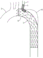
图10为分体式单内嵌分支覆膜支架用于重建主动脉弓的场景示意图。Fig. 10 is a schematic diagram of a scene where a split type single embedded branch covered stent is used for reconstruction of the aortic arch.

图11为主体支架另一示例性结构示意图。Fig. 11 is a schematic diagram of another exemplary structure of the main body bracket.

图12为图11中A处的放大结构示意图。FIG. 12 is a schematic diagram of an enlarged structure at point A in FIG. 11 .

附图标记说明:1、主体支架;10、管状覆膜;20、裸支架;201、锚定区;30、支撑骨架;3001、支撑杆;3002、波峰;3003、波谷;31、贴壁骨架;32、束径骨架;321、第一全固定骨架;322、第二全固定骨架;3221、高波;3222、低波;323、第二加强骨架;33、第一加强骨架;34、辅助骨架;341、自由区;35、远端骨架;36、加强部;361、第一支撑杆;362、第二支撑杆;363、加强波谷;364、第一贴壁波谷;365、第二贴壁波谷;366、第一避位波峰;367、第二避位波峰;40、柔性束径构件;401、柔性环;402、固定位点;403、线环;404、束径导丝;50、缝合线圈;60、连接结点;70、显影标记;2、内嵌支架;21、内嵌覆膜;22、内嵌骨架;3、分支支架;301、分支覆膜;302、支撑段;303、柔性段;304、贴壁段;305、翻折段;306、支撑骨环;3061、第一波形环;3062、第二波形环;3063、连接骨;3064、分支杆;3065、固定套;307、柔性骨环;371、波形单元;372、单元杆;308、贴壁骨环;4、开窗结构;5、主动脉弓;6、小弯侧;7、左锁骨动脉;8、瘤腔。Explanation of reference numerals: 1. main body support; 10. tubular coating; 20. bare support; 201. anchoring area; 30. support frame; 3001. support rod; 3002. peak; ;32, beam diameter frame; 321, first fully fixed frame; 322, second fully fixed frame; 3221, high wave; 3222, low wave; 323, second reinforced frame; 33, first reinforced frame; 34, auxiliary frame ; 341, free zone; 35, distal skeleton; 36, reinforced part; 361, first support rod; 362, second support rod; 363, reinforced trough; 364, first wall-attached trough; 365, second wall-attached trough; 366, first avoidance peak; 367, second avoidance peak; 40, flexible beam diameter member; 401, flexible ring; 402, fixed position; 403, wire ring; 404, beam diameter guide wire; 50, Suture coil; 60, connecting node; 70, developing mark; 2, embedded stent; 21, embedded membrane; 22, embedded skeleton; 3, branch bracket; 301, branch membrane; 302, support section; 303 , flexible segment; 304, adherent segment; 305, folded segment; 306, supporting bone ring; 3061, first wave ring; 3062, second wave ring; 3063, connecting bone; 3064, branch rod; 3065, fixed sleeve ;307, flexible bone ring; 371, wave-shaped unit; 372, unit rod; 308, adherent bone ring; 4, fenestration structure; 5, aortic arch; 6, lesser curvature; 7, left clavicle artery; 8, tumor cavity .

具体实施方式Detailed ways

下面将结合本申请实施方式中的附图,对本申请实施方式中的技术方案进行清楚、完整地描述,显然,所描述的实施方式仅仅是本申请一部分实施方式,而不是全部的实施方式。基于本申请中的实施方式,本领域普通技术人员在没有作出创造性劳动前提下所获得的所有其他实施方式,都属于本申请保护的范围。The following will clearly and completely describe the technical solutions in the embodiments of the application with reference to the accompanying drawings in the embodiments of the application. Apparently, the described embodiments are only part of the embodiments of the application, not all of them. Based on the implementation manners in this application, all other implementation manners obtained by persons of ordinary skill in the art without creative efforts shall fall within the scope of protection of this application.

对于介入医疗器械领域,近端是指将支架用于介入治疗后其靠近人体心脏的一端,远端是指支架用于介入治疗后其远离人体心脏的一端。将柱体、管体等一类物体的旋转中心轴的方向为轴向,与轴向垂直的方向为径向。周向就是指“圆周方向”,即绕柱体、管体等轴线方向(垂直于轴线,同时垂直于截面半径)。“周向”、“轴向”、“径向”共同构成柱坐标的三个正交方向。周向长度,是指结构或元件沿柱体、管体等的周向方向的延伸长度。轴向长度,是指结构或元件沿柱体、管体等的轴向方向的延伸长度。该种描述只是为了表述方便,并不构成对本申请的限制。以下的结构是指分体式单内嵌分支覆膜支架膨胀后的结构。For the field of interventional medical devices, the proximal end refers to the end of the stent close to the human heart after the interventional treatment, and the distal end refers to the end of the stent away from the human heart after the interventional treatment. The direction of the rotation center axis of objects such as cylinders and tubes is the axial direction, and the direction perpendicular to the axial direction is the radial direction. The circumferential direction refers to the "circumferential direction", that is, the direction around the axis of the cylinder, tube, etc. (perpendicular to the axis and perpendicular to the radius of the section). "Circumferential", "axial", and "radial" together constitute three orthogonal directions of cylindrical coordinates. Circumferential length refers to the extension length of a structure or element along the circumferential direction of a column, tube, etc. Axial length refers to the extension length of a structure or element along the axial direction of a column, tube, etc. This description is only for the convenience of expression, and does not constitute a limitation to the present application. The structure below refers to the expanded structure of the split-type single-embedded branch stent-graft.

为了改善现有的覆膜支架的分支支架在拉入分支动脉内时会对动脉内壁造成损失的问题,本申请第一实施例提供一种分体式单内嵌分支覆膜支架,可应用于血管中以实施腔内隔绝术来隔绝管腔内的病变区域或隔绝夹层破口,例如,可采用分体式单内嵌分支覆膜支架在血管的管腔中隔绝动脉夹层破口或动脉瘤等。可以理解,该血管可以是主动脉弓、胸主动脉,或腹主动脉等。本领域的普通技术人员应当知晓,采用血管来阐述仅用作举例,并不是对本申请的限制,本申请的方案适用于各种人体或动物管腔,例如消化道管腔等。In order to improve the problem that the branch stent of the existing stent-graft will cause damage to the inner wall of the artery when it is pulled into the branch artery, the first embodiment of the present application provides a split-type single-embedded branch stent-graft, which can be applied to blood vessels In this method, endoluminal isolation can be performed to isolate the lesion area in the lumen or the dissection breach. For example, a split-type single-embedded branch covered stent can be used to isolate the arterial dissection breach or aneurysm in the lumen of the blood vessel. It can be understood that the blood vessel may be the aortic arch, thoracic aorta, abdominal aorta, etc. Those of ordinary skill in the art should know that the use of blood vessels for illustration is only used as an example and not a limitation of the present application. The solutions of the present application are applicable to various human or animal lumens, such as digestive tract lumens.

请参阅图1及图2,图1为分体式单内嵌分支覆膜支架的结构示意图,图2为分体式单内嵌分支覆膜支架的另一视角的结构示意图。分体式单内嵌分支覆膜支架包括主体支架1、固定于主体支架1内壁的内嵌支架2及可拆卸连接于主体支架1的分支支架3,分支支架3用于重建分支动脉。主体支架1为两端开口的管状结构,主体支架1围合成用于和目标血管连通的连通腔(图中未示出)。主体支架1设有至少一开窗结构4,开窗结构4可以是圆形、椭圆形或其他不规则形状等。内嵌支架2为两端开口的管状结构,内嵌支架2的一端密封固定于开窗结构4,以使开窗结构4通过内嵌支架2与主体支架1的连通腔连通。分支支架3为两端开口的管状结构,分支支架3围合成用于和分支动脉连通的连接腔(图中未示出)。分支支架3通过开窗结构4插接于内嵌支架2内,以使分支支架3与连通腔连通,从而将流经连通腔内的血流引入分支支架3,重建分支动脉。分支支架3与主体支架1的可拆卸插接配合,能够减少心动周期内分支支架3对 LSA 远端血管壁的损伤刺激,进而保证分支动脉远期通畅率。Please refer to FIG. 1 and FIG. 2 . FIG. 1 is a schematic structural diagram of a split-type single embedded branch stent-graft, and FIG. 2 is a structural schematic diagram of a split-type single embedded branch stent-graft from another perspective. The split-type single embedded branch stent-graft includes a main body stent 1, an embedded stent 2 fixed on the inner wall of the main body stent 1, and a branch stent 3 detachably connected to the main body stent 1, and the branch stent 3 is used for reconstructing branch arteries. The main body stent 1 is a tubular structure with two ends open, and the main body stent 1 encloses a communicating cavity (not shown in the figure) for communicating with a target blood vessel. The main body bracket 1 is provided with at least one window opening structure 4, and the window opening structure 4 may be circular, oval or other irregular shapes. The embedded bracket 2 is a tubular structure with two ends open, and one end of the embedded bracket 2 is sealed and fixed to the window structure 4 so that the window structure 4 communicates with the communication cavity of the main body bracket 1 through the embedded bracket 2 . The branch stent 3 is a tubular structure with two ends open, and the branch stent 3 encloses a connecting cavity (not shown in the figure) for communicating with the branch artery. The branch stent 3 is plugged into the embedded stent 2 through the fenestration structure 4, so that the branch stent 3 communicates with the communicating cavity, so that the blood flowing through the communicating cavity is introduced into the branch stent 3, and the branch artery is reconstructed. The detachable plug-in cooperation between the branch stent 3 and the main body stent 1 can reduce the damage and stimulation of the branch stent 3 to the LSA distal vessel wall during the cardiac cycle, thereby ensuring the long-term patency of the branch artery.

请结合参阅图3及图4,图3为主体支架1的结构示意图(未示出柔性束径构件40),图4为主体支架1的平面展开图(未示出内嵌支架2)。主体支架1包括管状覆膜10、裸支架20、多个支撑骨架30及多组柔性束径构件40。裸支架20和支撑骨架30均呈环状结构,裸支架20固定于管状覆膜10的近端,多个支撑骨架30位于裸支架20的远端侧,多个支撑骨架30沿管状覆膜10的轴向依次排列固定。裸支架20和支撑骨架30均包括多个呈夹角依次相连的支撑杆3001,沿主体支架1的周向上,相邻的两个夹角分别为波峰3002和波谷3003,波峰3002相比波谷3003更靠近主体支架1的近端。裸支架20和支撑骨架30可以通过缝合、贴覆、冲压、贴设、镶设或热压等方式固定于管状覆膜10上。多组柔性束径构件40均位于开窗结构4的近端侧,柔性束径构件40用于径向压缩位于开窗结构4近端侧的局部主体支架1,即,开窗结构4的近端边缘至主体支架1近端边缘的区域能够被柔性束径构件40径向压缩以处于径向压缩状态,使得主体支架1进入目标血管后,至少部分径向压缩的主体支架1依然能够在目标血管内轴向移动或周向转动,从而便于精确调整开窗结构4的位置,使得开窗结构4更好地和分支动脉的根部开口对中,提高开窗结构4的定位精度。Please refer to FIG. 3 and FIG. 4 together. FIG. 3 is a schematic structural view of the main body stent 1 (the flexible beam diameter member 40 is not shown), and FIG. 4 is a planar development view of the main body stent 1 (the embedded bracket 2 is not shown). The main body stent 1 includes a tubular covering 10 , a bare stent 20 , a plurality of supporting frameworks 30 and a plurality of groups of flexible bundle diameter members 40 . Both the bare stent 20 and the support frame 30 are ring-shaped structures, the bare stent 20 is fixed on the proximal end of the tubular membrane 10, a plurality of support frameworks 30 are located at the distal side of the bare stent 20, and the plurality of support frameworks 30 are arranged along the tubular membrane 10. The axial direction is arranged in sequence and fixed. Both the bare bracket 20 and the supporting frame 30 include a plurality of supporting rods 3001 connected in sequence at angles. Along the circumferential direction of the main body bracket 1, the two adjacent angles are respectively a peak 3002 and a valley 3003, and the peak 3002 is compared with the valley 3003. Closer to the proximal end of the main body bracket 1. The bare stent 20 and the supporting frame 30 can be fixed on the tubular covering 10 by suturing, sticking, stamping, sticking, setting or hot pressing. A plurality of groups of flexible beam diameter members 40 are all located at the proximal side of the fenestration structure 4, and the flexible beam diameter members 40 are used to radially compress the local body stent 1 located at the proximal end side of the fenestration structure 4, that is, the proximal end of the fenestration structure 4 The region from the end edge to the proximal edge of the main body stent 1 can be radially compressed by the flexible beam diameter member 40 to be in a radially compressed state, so that after the main body stent 1 enters the target blood vessel, the at least partially radially compressed main body stent 1 can still be in the target blood vessel. Axial movement or circumferential rotation in the blood vessel facilitates precise adjustment of the position of the fenestration structure 4 , so that the fenestration structure 4 is better aligned with the root opening of the branch artery, and the positioning accuracy of the fenestration structure 4 is improved.

多个支撑骨架30包括贴壁骨架31、束径骨架32、至少一第一加强骨架33、辅助骨架34及远端骨架35,贴壁骨架31、束径骨架32、至少一第一加强骨架33、辅助骨架34及远端骨架35沿管状覆膜10的近端至管状覆膜10的远端依次排列固定。贴壁骨架31和束径骨架32均位于开窗结构4的近端侧,辅助骨架34、远端骨架35及至少一第一加强骨架33均位于开窗结构4的远端侧。A plurality of supporting frames 30 includes an adherent frame 31, a beam diameter frame 32, at least one first reinforcing frame 33, an auxiliary frame 34 and a distal frame 35, an adherent frame 31, a beam diameter frame 32, and at least one first reinforcing frame 33 , the auxiliary frame 34 and the distal frame 35 are arranged and fixed sequentially along the proximal end of the tubular membrane 10 to the distal end of the tubular membrane 10 . The sticking frame 31 and beam diameter frame 32 are located at the proximal side of the fenestration structure 4 , and the auxiliary frame 34 , the distal frame 35 and at least one first reinforcing frame 33 are all located at the distal side of the fenestration structure 4 .

裸支架20的波谷3003固定于管状覆膜10上,裸支架20的波峰3002和裸支架20的支撑杆3001至少局部延伸出管状覆膜10的近端,即裸支架20的支撑杆3001的至少局部及裸支架20的波峰3002未被管状覆膜10覆盖,换而言之,沿支撑杆3001的轴向方向,支撑杆3001至少局部未被管状覆膜10覆盖,且裸支架20的波峰3002未被管状覆膜10覆盖。裸支架20的波谷3003通过缝合线加密缝合固定有多个缝合线圈50以将裸支架20的波谷3003固定于管状覆膜10的近端(即多个缝合线圈50之间紧密相邻),支撑杆3001通过缝合线缝合固定有至少一个缝合线圈50以将裸支架20的支撑杆3001固定于管状覆膜10,且支撑杆3001上的缝合线圈50与裸支架20的波谷3003上的缝合线圈50紧密相邻。裸支架20的波谷3003和支撑杆3001通过缝合线圈50固定于管状覆膜10的轴向长度形成了锚定区201,锚定区201的轴向长度至少为3-5mm,即,裸支架20被管状覆膜10覆盖的轴向长度为3-5mm,且裸支架20被管状覆膜10覆盖的部分通过缝合线圈50固定于管状覆膜10。在其他一些实施方式中,缝合线圈50的示例性形成方式可以是:以支撑骨架30固定于管状覆膜10的外周壁举例说明,将支撑杆3001长度方向的两侧分别命名为第一侧和第二侧,缝合线的一端固定于管状覆膜10的外周壁,步骤S1,将缝合线的另一端沿支撑杆3001的第一侧穿入管状覆膜10的内周壁,步骤S2,紧接着缝合线从管状覆膜10的内周壁沿支撑杆3001的第二侧穿出至管状覆膜10的外周壁,步骤S3,随后缝合线包绕支撑杆3001并从支撑杆3001的第一侧穿入至管状覆膜10的内周壁,步骤S1-步骤S3完成后即形成一大致呈环状结构的缝合线圈50。最后沿支撑骨架30的形状走势重复步骤S1-步骤S3以将裸支架20、支撑骨架30固定于管状覆膜10。The trough 3003 of the bare stent 20 is fixed on the tubular covering 10, the crest 3002 of the bare stent 20 and the support rod 3001 of the bare stent 20 at least partially extend out of the proximal end of the tubular covering 10, that is, at least part of the support rod 3001 of the bare stent 20 The peak 3002 of the partial and bare stent 20 is not covered by the tubular coating 10, in other words, along the axial direction of the support rod 3001, the support rod 3001 is at least partially not covered by the tubular coating 10, and the peak 3002 of the bare stent 20 Not covered by the tubular membrane 10 . The trough 3003 of the bare stent 20 is fixed with a plurality of suture coils 50 by dense sutures to fix the trough 3003 of the bare stent 20 to the proximal end of the tubular covering 10 (that is, the multiple suture coils 50 are closely adjacent to each other), supporting The rod 3001 is sutured with at least one suture coil 50 to fix the support rod 3001 of the bare stent 20 to the tubular covering 10, and the suture coil 50 on the support rod 3001 is connected with the suture coil 50 on the valley 3003 of the bare stent 20 closely adjacent. The trough 3003 and the support rod 3001 of the bare stent 20 are fixed to the axial length of the tubular graft 10 through the suture coil 50 to form an anchoring region 201, and the axial length of the anchoring region 201 is at least 3-5mm, that is, the bare stent 20 The axial length covered by the tubular membrane 10 is 3-5 mm, and the part of the bare stent 20 covered by the tubular membrane 10 is fixed to the tubular membrane 10 by suturing coils 50 . In some other embodiments, the exemplary formation method of the suture coil 50 may be as follows: taking the support frame 30 fixed on the outer peripheral wall of the tubular membrane 10 as an example, the two sides in the length direction of the support rod 3001 are named as the first side and the first side respectively. On the second side, one end of the suture is fixed on the outer peripheral wall of the tubular covering 10, step S1, the other end of the suture is inserted into the inner peripheral wall of the tubular covering 10 along the first side of the support rod 3001, step S2, followed by The suture thread passes from the inner peripheral wall of the tubular covering 10 to the outer peripheral wall of the tubular covering 10 along the second side of the support rod 3001, step S3, then the suture wraps around the support rod 3001 and passes through the first side of the support rod 3001 Inserted into the inner peripheral wall of the tubular covering film 10, a suture coil 50 with a substantially ring-shaped structure is formed after the steps S1-S3 are completed. Finally, steps S1 to S3 are repeated along the shape trend of the support frame 30 to fix the bare stent 20 and the support frame 30 to the tubular membrane 10 .

贴壁骨架31、束径骨架32、至少一第一加强骨架33及远端骨架35的波峰3002、波谷3003和支撑杆3001均通过缝合线缝合固定于管状覆膜10,例如波峰3002和波谷3003均通过缝合线加密缝合固定有多个缝合线圈50(即多个缝合线圈50之间紧密相邻),支撑杆3001间隔设置至少一个缝合线圈50,以使缝合线将贴壁骨架31、束径骨架32、至少一第一加强骨架33及远端骨架35贴合固定于管状覆膜10,进而使得贴壁骨架31、束径骨架32、至少一第一加强骨架33及远端骨架35几乎完全贴合管状覆膜10固定,既提高贴壁骨架31、束径骨架32、至少一第一加强骨架33及远端骨架35的径向支撑力,也有利于避免束径骨架32钩挂到柔性束径构件40,从而有利于柔性束径构件40的解脱以释放主体支架1,使主体支架1自膨胀以顺利恢复至预定形态。The crests 3002, troughs 3003, and support rods 3001 of the adherent frame 31, beam diameter frame 32, at least one first reinforcement frame 33, and the distal frame 35 are all fixed to the tubular membrane 10 by sutures, such as the crests 3002 and troughs 3003 All of them are fixed with a plurality of suture coils 50 (that is, the multiple suture coils 50 are closely adjacent to each other) through intensive suture with suture threads, and at least one suture coil 50 is arranged at intervals on the support rod 3001, so that the suture threads will adhere to the wall skeleton 31, beam diameter The frame 32, at least one first reinforcing frame 33, and the distal frame 35 are fitted and fixed on the tubular covering 10, so that the wall-attached frame 31, beam diameter frame 32, at least one first reinforcing frame 33, and the distal frame 35 are almost completely Fitting the tubular film 10 for fixation not only improves the radial support force of the adherent frame 31, the beam diameter frame 32, at least one first reinforcement frame 33 and the distal frame 35, but also helps to prevent the beam diameter frame 32 from being hooked to the flexible frame. The bundle diameter member 40 facilitates the disengagement of the flexible bundle diameter member 40 to release the main body stent 1 , so that the main body stent 1 self-expands to return to a predetermined shape smoothly.

至少一贴壁骨架31位于开窗结构4的近端侧。贴壁骨架31的波形走势与裸支架20的波形走势保持一致,即,贴壁骨架31的波峰3002与裸支架20的波峰3002在轴向上相对,第一全固定骨架321的波谷3003与裸支架20的波谷3003在轴向上相对,使得贴壁骨架31的波峰3002能够位于裸支架20相邻两个支撑杆3001之间的区域,有利于避免管状覆膜10的近端在植入目标血管后,由于目标血管的解剖结构较为弯曲而导致管状覆膜10近端容易打皱,有利于减少Ia型内漏的发生。将裸支架20上的支撑杆3001与管状覆膜10的近端边缘交叉的点以及贴壁骨架31的波峰3002与管状覆膜10的接触点均命名为连接结点60,裸支架20的锚定区201的轴向长度的设置,使得各连接结点60沿管状覆膜10的周向排布更为合理,避免任意相邻两个连接结点60之间沿周向上的间距相差太大,即锚定区201的轴向长度的设置使得各连接结点60沿管状覆膜10的周向排布更为均匀,有利于进一步避免管状覆膜10的近端植入弯曲的目标血管后发生打皱的问题,从而更好的起到防内漏的效果。贴壁骨架31的波峰3002固定于管状覆膜10靠近近端边缘的位置,使得锚定区201的轴向长度大致为裸支架20与贴壁骨架31在轴向上的重合长度(即贴壁骨架31的波峰3002与管状覆膜10的近端边缘的距离允许有±1.5mm的误差),裸支架20的锚定区201的轴向长度的设置使得主体支架1径向收缩或者径向自膨胀的过程中,贴壁骨架31的波形走势与裸支架20的波形走势保持一致,有利于避免主体支架1近端在径向收缩或径向自膨胀的过程中变形,从而使得主体支架1与血管壁之间的贴壁性更好,进一步提高防内漏的效果。贴壁骨架31中,各支撑杆3001沿管状覆膜10的轴向长度相同,以增强主体支架1近端的径向支撑力,从而有利于减少主体支架1植入目标血管之后由于高流量血流的冲击而发生位移的风险。At least one wall-attached framework 31 is located on the proximal side of the fenestration structure 4 . The waveform trend of the adherent framework 31 is consistent with that of the bare stent 20, that is, the peak 3002 of the adherent framework 31 is opposite to the peak 3002 of the bare stent 20 in the axial direction, and the wave trough 3003 of the first fully fixed framework 321 is opposite to that of the bare stent 20 in the axial direction. The troughs 3003 of the stent 20 are opposite in the axial direction, so that the crests 3002 of the adherent framework 31 can be located in the area between two adjacent support rods 3001 of the bare stent 20, which is beneficial to avoid the proximal end of the tubular membrane 10 from being placed on the implantation target. After the blood vessel, because the anatomical structure of the target blood vessel is relatively curved, the proximal end of the tubular membrane 10 is easy to wrinkle, which is beneficial to reduce the occurrence of type Ia endoleak. The point where the strut 3001 on the bare stent 20 intersects with the proximal edge of the tubular covering 10 and the contact point between the crest 3002 of the adherent skeleton 31 and the tubular covering 10 are both named connection nodes 60, the anchor of the bare stent 20 The setting of the axial length of the fixed area 201 makes the arrangement of the connecting nodes 60 along the circumferential direction of the tubular coating 10 more reasonable, and avoids too large a difference in the circumferential distance between any two adjacent connecting nodes 60 , that is, the setting of the axial length of the anchoring area 201 makes the arrangement of the connecting nodes 60 more uniform along the circumferential direction of the tubular membrane 10, which is beneficial to further avoid The problem of wrinkling occurs, so as to better prevent internal leakage. The crest 3002 of the adherent framework 31 is fixed at the position near the proximal edge of the tubular covering 10, so that the axial length of the anchoring area 201 is approximately the overlapping length of the bare stent 20 and the adherent framework 31 in the axial direction (ie, the length of the adherent The distance between the crest 3002 of the skeleton 31 and the proximal edge of the tubular covering 10 is allowed to have an error of ±1.5mm), the axial length of the anchoring area 201 of the bare stent 20 is set so that the main body stent 1 radially shrinks or radially During the expansion process, the waveform trend of the adherent skeleton 31 is consistent with the waveform trend of the bare stent 20, which is beneficial to avoid deformation of the proximal end of the main body stent 1 during radial contraction or radial self-expansion, so that the main body stent 1 and the The adherence between the blood vessel walls is better, further improving the effect of preventing endoleak. In the adherent framework 31, each support rod 3001 has the same axial length along the tubular covering 10, so as to enhance the radial support force of the proximal end of the main body stent 1, thereby helping to reduce the risk of blood flow due to high flow after the main body stent 1 is implanted in the target blood vessel. The risk of displacement due to the impact of the current.

束径骨架32包括至少一第一全固定骨架321、至少一第二全固定骨架322及至少一第二加强骨架323,至少一第一全固定骨架321、至少一第二全固定骨架322及至少一第二加强骨架323沿管状覆膜10的近端至远端依次排列固定。至少一第一全固定骨架321可以位于开窗结构4的近端侧。至少一第一全固定骨架321位于至少一贴壁骨架31的远端侧,且第一全固定骨架321的波长小于其他支撑骨架30的波长,换而言之,至少一第一全固定骨架321的波形相比其他支撑骨架30的波形更为密集,使得主体支架1的近端更好地贴合血管壁,降低Ia型内漏的风险。至少一第一全固定骨架321上各支撑杆3001沿主体支架1的轴向长度均相同,以进一步增加主体支架1近端有的径向支撑力,从而有利于减少主体支架1植入目标血管之后由于高流量血流的冲击而发生位移的风险。Beam diameter frame 32 includes at least one first fully fixed frame 321, at least one second fully fixed frame 322 and at least one second reinforced frame 323, at least one first fully fixed frame 321, at least one second fully fixed frame 322 and at least one A second reinforcing frame 323 is arranged and fixed sequentially along the proximal end to the distal end of the tubular membrane 10 . At least one first full fixation frame 321 can be located at the proximal side of the fenestration structure 4 . At least one first fully fixed framework 321 is located at the distal side of at least one wall-attached framework 31, and the wavelength of the first fully fixed framework 321 is smaller than the wavelength of other supporting frameworks 30, in other words, at least one first fully fixed framework 321 Compared with the waveforms of other supporting frameworks 30, the waveform of the main body stent 1 is denser, so that the proximal end of the main body stent 1 fits the blood vessel wall better, and reduces the risk of type Ia endoleak. The axial lengths of the support rods 3001 on at least one first fully fixed frame 321 along the main body stent 1 are the same, so as to further increase the radial support force at the proximal end of the main body stent 1, thereby helping to reduce the number of implants of the main body stent 1 into the target blood vessel. There is a risk of subsequent displacement due to the impact of high flow blood flow.

至少一第二全固定骨架322位于开窗结构4的近端侧。至少一第三固定骨架上的各支撑杆3001的轴向长度不同,具体地,沿主体支架1的周向上,相邻两个波峰3002中包括高波3221和低波3222,高波3221相比低波3222更靠近主体支架1的近端。沿主体支架1的周向上,高波3221和低波3222交替设置,从而有利于降低主体支架1近端的回直力,提高主体支架1近端的柔顺性,使得主体支架1的近端更好的贴合弯曲的血管解剖结构,有利于降低Ia型内漏的发生风险。At least one second full fixation frame 322 is located at the proximal side of the fenestration structure 4 . The axial lengths of the support rods 3001 on at least one third fixed frame are different. Specifically, along the circumferential direction of the main body bracket 1, two adjacent crests 3002 include a high wave 3221 and a low wave 3222. Compared with the low wave, the high wave 3221 3222 is closer to the proximal end of the body stent 1 . Along the circumferential direction of the main body stent 1, the high wave 3221 and the low wave 3222 are arranged alternately, which is beneficial to reduce the straightening force of the proximal end of the main body stent 1, improve the flexibility of the proximal end of the main body stent 1, and make the proximal end of the main body stent 1 better. Fitting the anatomical structure of the curved blood vessel, it is beneficial to reduce the risk of type Ia endoleak.

在其他实施方式中,例如请参阅图5,图5为主体支架1另一可能实施方式的平面展开图。也可以省略第二全固定骨架322的设置。In other embodiments, for example, please refer to FIG. 5 , which is a plan development view of another possible embodiment of the main body bracket 1 . The setting of the second full fixed frame 322 can also be omitted.

在本实施例中,第一加强骨架33和第二加强骨架323在轴向上相邻设置,第一加强骨架33和第二加强骨架323分别位于开窗结构4轴向上的两侧,即第一加强骨架33位于开窗结构4的远端侧,第二加强骨架323位于开窗结构4的近端侧。第一加强骨架33上的各支撑杆3001的轴向长度均相同,第二加强骨架323上的各支撑杆3001的轴向长度均相同。第一加强骨架33和第二加强骨架323的设置用于增强开窗结构4周围的径向支撑力,使得开窗结构4能够更为充分的和血管壁接触,有利于改善开窗结构4被挤压变形(例如钙化斑块、不规则的血管截面等对主体支架1的挤压)的问题。对于第一加强骨架33和第二加强骨架323上的波峰3002和波谷3003,第一加强骨架33上的波峰3002和第二加强骨架323上的波谷3003在轴向上相对,第一加强骨架33上的波谷3003和第二加强骨架323上的波峰3002在轴向上相对,从而有利于改善主体支架1靠近开窗结构4的部分发生轴向短缩的问题,充分保证开窗结构4从径向压缩状态回复至预定形态,同时,能够为开窗结构4预留更为充足的空间,进一步充分保证开窗结构4从径向压缩状态回复至预定形态。In this embodiment, the first reinforcing frame 33 and the second reinforcing frame 323 are arranged adjacent to each other in the axial direction, and the first reinforcing frame 33 and the second reinforcing frame 323 are located on both sides of the window structure 4 in the axial direction, namely The first reinforcing frame 33 is located at the distal side of the fenestration structure 4 , and the second reinforcing frame 323 is located at the proximal end side of the fenestration structure 4 . The axial lengths of the supporting rods 3001 on the first reinforcing frame 33 are the same, and the axial lengths of the supporting rods 3001 on the second reinforcing frame 323 are the same. The setting of the first reinforcement frame 33 and the second reinforcement frame 323 is used to enhance the radial support force around the fenestration structure 4, so that the fenestration structure 4 can be more fully in contact with the blood vessel wall, which is beneficial to improve the fenestration structure 4 Extrusion deformation (such as extrusion of calcified plaque, irregular blood vessel section, etc. on the main body stent 1). For the peaks 3002 and troughs 3003 on the first reinforcement skeleton 33 and the second reinforcement skeleton 323, the peaks 3002 on the first reinforcement skeleton 33 and the troughs 3003 on the second reinforcement skeleton 323 are axially opposite, and the first reinforcement skeleton 33 The trough 3003 on the top and the crest 3002 on the second reinforcing frame 323 are opposite in the axial direction, which helps to improve the problem of axial shortening of the part of the main body bracket 1 close to the window structure 4, and fully ensures that the window structure 4 is Returning to the predetermined form from the compressed state, at the same time, more sufficient space can be reserved for the window structure 4, which further fully ensures that the window structure 4 returns to the predetermined form from the radially compressed state.

在其他实施方式中,第一加强骨架33上的轴向长度也可以不相同,第二加强骨架323上的轴向长度也可以不相同,即,沿主体支架1的周向上,第一加强骨架33和第二加强骨架323上相邻的两个波峰3002中包括高波3221和低波3222,高波3221相比低波3222更靠近管状覆膜10的近端。沿主体支架1的周向上,高波3221和低波3222交替设置,以进一步提高主体支架1近端的柔顺性,改善鸟嘴征效应。In other embodiments, the axial length of the first reinforcing skeleton 33 may also be different, and the axial length of the second reinforcing skeleton 323 may also be different, that is, along the circumferential direction of the main body bracket 1, the first reinforcing skeleton 33 and the two adjacent crests 3002 on the second reinforcing frame 323 include a high wave 3221 and a low wave 3222 , and the high wave 3221 is closer to the proximal end of the tubular covering 10 than the low wave 3222 . Along the circumferential direction of the main body stent 1 , high waves 3221 and low waves 3222 are arranged alternately to further improve the flexibility of the proximal end of the main body stent 1 and improve the bird's beak effect.

根据本申请的示例性实施例,在一些示例性实施例中,也可以省略第二加强骨架323的设置,使得开窗结构4位于至少一第一全固定骨架321和第一加强骨架33之间。According to the exemplary embodiment of the present application, in some exemplary embodiments, the setting of the second reinforcing frame 323 can also be omitted, so that the window structure 4 is located between at least one first full fixed frame 321 and the first reinforcing frame 33 .

辅助骨架34设置有至少两个,至少两个辅助骨架34上的支撑杆3001的轴向长度不相同,即,沿主体支架1的周向上,辅助骨架34上相邻的两个波峰3002中包括高波3221和低波3222,高波3221相比低波3222更靠近管状覆膜10的近端。沿管状覆膜10的周向上,高波3221和低波3222交替设置。靠近管状覆膜10近端的辅助骨架34上的高波3221与靠近管状覆膜10远端的辅助骨架34上的低波3222在轴向上相对,靠近管状覆膜10近端的辅助骨架34上的波谷3003与靠近管状覆膜10远端的辅助骨架34上的波谷3003在轴向上相对,使得至少两个辅助骨架34的波形走势大致相同。The auxiliary frame 34 is provided with at least two, and the axial lengths of the support rods 3001 on the at least two auxiliary frames 34 are different, that is, along the circumferential direction of the main frame 1, two adjacent peaks 3002 on the auxiliary frame 34 include The high wave 3221 and the low wave 3222, the high wave 3221 is closer to the proximal end of the tubular graft 10 than the low wave 3222. Along the circumferential direction of the tubular membrane 10, high waves 3221 and low waves 3222 are arranged alternately. The high wave 3221 on the auxiliary framework 34 near the proximal end of the tubular membrane 10 is axially opposite to the low wave 3222 on the auxiliary framework 34 near the distal end of the tubular membrane 10 , and on the auxiliary framework 34 near the proximal end of the tubular membrane 10 The trough 3003 of the trough is opposite to the trough 3003 on the auxiliary frame 34 near the distal end of the tubular membrane 10 in the axial direction, so that the waveform trends of at least two auxiliary frames 34 are approximately the same.

辅助骨架34的低波3222、波谷3003和支撑杆3001均通过缝合线缝合固定于管状覆膜10,例如低波3222和波谷3003均通过缝合线加密缝合固定有多个缝合线圈50(即多个缝合线圈50之间紧密相邻),支撑杆3001间隔设置至少一个缝合线圈50,以使缝合线将辅助骨架34缝合固定于管状覆膜10。辅助骨架34的高波3221与管状覆膜10之间具有间隙且辅助骨架34的高波3221能够和管状覆膜10分离从而形成自由区341,即,辅助骨架34的高波3221无需通过缝合线固定于管状覆膜10,或者,辅助支架的高波3221无需通过贴覆、冲压、贴设、镶设或热压等方式固定于管状覆膜10,使得辅助骨架34的高波3221相比辅助骨架34的低波3222具有更多的变形空间。自由区341的轴向长度为2.5-4mm,保证辅助骨架34的高波3221具有充足的活动空间。The low wave 3222, the wave trough 3003 and the support rod 3001 of the auxiliary frame 34 are all fixed to the tubular covering 10 by sutures. The suture coils 50 are closely adjacent to each other), and at least one suture coil 50 is arranged at intervals on the support rod 3001 , so that the suture thread can suture and fix the auxiliary framework 34 to the tubular graft 10 . There is a gap between the high wave 3221 of the auxiliary frame 34 and the tubular covering 10 and the high wave 3221 of the auxiliary frame 34 can be separated from the tubular covering 10 to form a free area 341, that is, the high wave 3221 of the auxiliary frame 34 does not need to be fixed to the tubular covering 10 by sutures. The covering film 10, or the high wave 3221 of the auxiliary bracket does not need to be fixed on the tubular covering film 10 by sticking, punching, sticking, setting or hot pressing, so that the high wave 3221 of the auxiliary frame 34 is lower than the low wave of the auxiliary frame 34. 3222 has more room for deformation. The axial length of the free zone 341 is 2.5-4 mm, which ensures that the high wave 3221 of the auxiliary frame 34 has sufficient space for movement.

主体支架1植入弯曲的目标血管之后,例如主体支架1植入主动脉弓5之后,主体支架1为了适应主动脉弓5拱起的弓部,主体支架1靠近血管小弯侧6(请参阅图10)的一侧需要适应性弯曲,则主体支架1上的支撑骨架30的波峰3002和波谷3003可以在轴向上相互靠近,辅助骨架34上高波3221和低波3222的交替设置以及高波3221的自由区341设置,使得辅助骨架34靠近血管小弯侧6的一侧有更大的变形空间,即,相邻两个辅助骨架34靠近血管小弯侧6一侧的支撑杆3001可以有更多的轴向变形以增加轴向重合长度,同时,高波3221能够向远离主体支架1中轴线的方向与轴向上相邻的支撑骨架30在轴向上折叠,高波3221的自由区341设置带动相邻的波谷3003向靠近主体支架1中轴线的方向与轴向上相邻的支撑骨架30在轴向上折叠,从而使得主体支架1靠近血管小弯侧6的一侧更加贴合血管的弯曲曲线,降低内漏的发生。目标血管的拱起幅度越大,则辅助骨架34靠近血管小弯侧6一侧的支撑杆3001的轴向变形程度越大。After the main body stent 1 is implanted into a curved target vessel, for example, after the main body stent 1 is implanted into the aortic arch 5, in order to adapt to the arched portion of the aortic arch 5, the main body stent 1 is close to the lesser curved side 6 of the vessel (see Figure 10). If one side needs to be adaptively bent, then the crests 3002 and troughs 3003 of the supporting frame 30 on the main frame 1 can approach each other in the axial direction, the alternate arrangement of high waves 3221 and low waves 3222 on the auxiliary frame 34 and the free area 341 of the high waves 3221 It is set so that the side of the auxiliary frame 34 close to the lesser curvature of the blood vessel 6 has a larger deformation space, that is, the support rods 3001 of two adjacent auxiliary frames 34 near the side of the lesser curvature of the blood vessel 6 can have more axial Deformation to increase the axial overlap length, at the same time, the high wave 3221 can be folded in the axial direction with the axially adjacent support frame 30 in a direction away from the central axis of the main body bracket 1, and the free area 341 of the high wave 3221 is set to drive the adjacent wave trough 3003 is folded in the axial direction with the axially adjacent support frame 30 in the direction close to the central axis of the main body stent 1, so that the side of the main body stent 1 close to the lesser curved side 6 of the blood vessel fits the curved curve of the blood vessel more closely, reducing the internal Leakage occurs. The greater the degree of arching of the target blood vessel, the greater the degree of axial deformation of the support rod 3001 on the side of the auxiliary frame 34 near the lesser curvature side 6 of the blood vessel.

远端骨架35设有至少两个,至少两个远端骨架35沿管状覆膜10的轴向依次排列。远端骨架35上各支撑杆3001的轴向长度相同,以增加主体支架1远端的径向支撑力,有利于改善主体支架1植入目标血管后容易发生位移的问题。管状覆膜10的远端设有至少一显影标记70,显影标记70位于靠近管状覆膜10的远端口的至少两个远端骨架35的近端或者近端侧,即,显影标记70可以固定于远端骨架35上,以使显影标记70位于靠近管状覆膜10的远端口的至少两个远端骨架35的近端;显影标记70也可以固定于管状覆膜10上,以使显影标记70位于靠近管状覆膜10的远端口的至少两个远端骨架35的近端侧。显影标记70与管状覆膜10的远端边缘的轴向长度至少为30-50mm。显影标记70用于指示另一外接支架插接于主体支架1的位置,使得外接支架与主体支架1具有充足的重合轴向长度,为外接支架提供充足的锚定长度。管状覆膜10的近端也可以固定有至少一显影标记70以用于指示主体支架1的近端位置;管状覆膜10的远端也可以固定有至少一显影标记70以用于指示主体支架1的远端位置。管状覆膜10上环绕开窗结构4的周向也可以固定有多个显影标记70。在其他一些实施方式中,环绕开窗结构4的周向的显影标记70为四个,其中两个显影标记70位于开窗结构4沿主体支架1轴向上的两侧,另外两个显影标记70位于开窗结构4沿主体支架1周向上的两侧。开窗结构4轴向两侧的两个显影标记70便于开窗结构4最大限度的和分支动脉的根部开口边缘对位,便于手术操作者判断开窗结构4的释放完成度,即便于判断开窗结构4是否释放到最大直径;开窗结构4周向两侧的两个显影标记70便于手术操作者判断在主体支架1释放后两个显影标记70的重合情况,如果开窗结构4周向上的两个显影标记70未重合,手术操作者可以再次调整主体支架1的位置以调整开窗结构4的位置,直至开窗结构4周向上的两个显影标记70重合,从而较好的保证开窗结构4更完全的和分支动脉的根部开口吻合,保证了分支支架3释放的定位精准,明显降低术中操作难度。There are at least two distal skeletons 35 , and at least two distal skeletons 35 are arranged in sequence along the axial direction of the tubular membrane 10 . The axial lengths of the support rods 3001 on the distal frame 35 are the same to increase the radial support force of the distal end of the main body stent 1, which is beneficial to improve the problem that the main body stent 1 is prone to displacement after being implanted in the target blood vessel. The distal end of the tubular covering film 10 is provided with at least one developing mark 70, and the developing mark 70 is located at the proximal end or the proximal end side of at least two distal skeletons 35 close to the distal end of the tubular covering film 10, that is, the developing mark 70 can be fixed On the distal skeleton 35, so that the development mark 70 is located at the proximal end of at least two distal skeletons 35 close to the distal port of the tubular film 10; the development mark 70 can also be fixed on the tubular film 10, so that the development mark 70 is located on the proximal side of at least two distal skeletons 35 near the distal port of the tubular graft 10 . The axial length of the visualized marker 70 and the distal edge of the tubular covering 10 is at least 30-50 mm. The developing mark 70 is used to indicate the position where another external support is plugged into the main support 1 , so that the external support and the main support 1 have sufficient overlapping axial lengths to provide sufficient anchoring length for the external support. The proximal end of the tubular covering 10 can also be fixed with at least one developing mark 70 for indicating the proximal position of the main body stent 1; the distal end of the tubular covering 10 can also be fixed with at least one developing mark 70 for indicating the main body stent 1 in the remote position. A plurality of developing marks 70 may also be fixed on the tubular film 10 around the circumference of the window structure 4 . In some other embodiments, there are four developing marks 70 around the window opening structure 4 in the circumferential direction, two of which are located on both sides of the window opening structure 4 along the axial direction of the main body bracket 1, and the other two developing marks 70 are located on both sides of the window opening structure 4 along the circumferential direction of the main body support 1 . The two development marks 70 on both sides of the fenestration structure 4 in the axial direction facilitate the alignment of the fenestration structure 4 with the edge of the root opening of the branch artery to the maximum extent, and it is convenient for the operator to judge the release completion degree of the fenestration structure 4, that is, to judge the opening Whether the window structure 4 is released to the maximum diameter; the two developing marks 70 on both sides of the window structure 4 are convenient for the operator to judge the coincidence of the two developing marks 70 after the main body support 1 is released. The two developing marks 70 do not coincide, and the operator can adjust the position of the main frame 1 again to adjust the position of the window structure 4 until the two developing marks 70 on the 4 circumference of the window structure overlap, so as to better ensure the opening The window structure 4 more completely coincides with the root opening of the branch artery, which ensures the precise positioning of the release of the branch stent 3 and significantly reduces the difficulty of operation during the operation.

显影标记70的材料可由不透X射线性能好、耐腐蚀性强、生物相容性好的材料制成,可以是金、铂、钽、锇、铼、钨、铱、铑等材料或这些材料的合金。可以理解,显影标记70也可以理解为对应的远端骨架35或者管状覆膜10的对应位置具有显影材料;或者,可以是管状覆膜10的对应位置设有显影标记70,也可以是对应的远端骨架35或开窗结构4分别设有显影标记70,显影标记70至少环绕部分远端骨架35或开窗结构4设置。The material of the developing mark 70 can be made of materials with good X-ray opacity, strong corrosion resistance, and good biocompatibility, and can be materials such as gold, platinum, tantalum, osmium, rhenium, tungsten, iridium, rhodium, or these materials alloy. It can be understood that the development mark 70 can also be understood as having a development material at the corresponding position of the corresponding distal end skeleton 35 or the tubular coating 10; The distal frame 35 or the fenestration structure 4 is respectively provided with a developing mark 70 , and the developing mark 70 is arranged around at least part of the distal frame 35 or the fenestration structure 4 .

请结合参阅图4和图6,图6为柔性束径构件40与外接束径导丝404配合以径向压缩部分主体支架1的结构示意图。柔性束径构件40为一环状结构,柔性束径构件40的环上任意两点固定于支撑骨架30以形成两个固定位点402(例如通过缝合、贴覆、冲压、贴设、镶设或热压等方式固定于支撑骨架30上以形成固定位点402),从而使柔性束径构件40形成至少两个柔性环401。两个固定位点402可以大致重合,以使柔性环401的长度方向能够沿管状覆膜10的周向方向排布。两个固定位点402也可以不重合,例如两个固定位点402可以在周向间隔一定距离、在轴向上间隔一定距离或者同时在周向和轴向上均间隔有一定距离,能够使得至少部分柔性环401的长度方向沿管状覆膜10的周向方向排布。本实施例中,柔性束径构件40上的至少两个固定位点402可以大致重合以形成重合固定点,多组柔性束径构件40形成的多个重合固定点大致沿主体支架1的轴向方向排列延伸。可以理解,在其他实施方式中,至少两个柔性环401也可以各自独立成形,而不是由同一环状结构通过设置至少两个固定位点402分离得到,例如,柔性束径构件40包括至少两个柔性环401,柔性环401长度方向的一端固定于管状覆膜10和支撑骨架30的至少一者以形成固定位点402。Please refer to FIG. 4 and FIG. 6 in conjunction. FIG. 6 is a structural schematic diagram of the flexible bundle diameter member 40 cooperating with the circumscribed bundle diameter guide wire 404 to radially compress part of the main body stent 1 . The flexible bundle diameter member 40 is an annular structure, and any two points on the ring of the flexible bundle diameter member 40 are fixed to the support frame 30 to form two fixed points 402 (for example, by suturing, sticking, stamping, sticking, setting or hot pressing to form a fixing point 402 ), so that the flexible beam path member 40 forms at least two flexible rings 401 . The two fixing points 402 can be roughly coincident, so that the length direction of the flexible ring 401 can be arranged along the circumferential direction of the tubular membrane 10 . The two fixing points 402 may not coincide. For example, the two fixing points 402 may be spaced at a certain distance in the circumferential direction, at a certain distance in the axial direction, or at the same time in both the circumferential direction and the axial direction, so that The length direction of at least part of the flexible ring 401 is arranged along the circumferential direction of the tubular membrane 10 . In this embodiment, at least two fixed points 402 on the flexible beam diameter member 40 can be roughly overlapped to form coincident fixed points, and the multiple coincident fixed points formed by multiple groups of flexible beam diameter members 40 are roughly along the axial direction of the main body stent 1 The directions are aligned and extended. It can be understood that, in other embodiments, at least two flexible rings 401 can also be formed independently, instead of being separated from the same ring structure by setting at least two fixing points 402, for example, the flexible beam path member 40 includes at least two A flexible ring 401 , one end of the flexible ring 401 in the length direction is fixed to at least one of the tubular membrane 10 and the supporting frame 30 to form a fixing point 402 .

多组柔性束径构件40从管状覆膜10的近端至远端依次排列,且多组柔性束径构件40均位于开窗结构4的近端侧。对于同一柔性束径构件40,将至少两个柔性环401远离固定位点402的一端沿主体支架1的周向相互靠近,直至至少两个柔性环401远离固定位点402的一端能够相互重合以形成供束径导丝404穿设的线环403,柔性环401的长度方向能够沿主体支架1的周向排布,至少两个柔性环401的长度方向能够围抱主体支架1的周向以使主体支架1能够径向压缩。多组柔性束径构件40形成的多个线环403大致沿主体支架1的轴向方向排列延伸,将一束径导丝404沿主体支架1的轴向依次穿设各个线环403,使得每一柔性束径构件40上的至少两个柔性环401能够形成沿主体支架1的周向围抱主体支架1的环状物,束径导丝404起到维持环状物的作用,从而使得主体支架1的部分轴向长度呈径向压缩状态。主体支架1植入目标血管后,径向压缩的主体支架1依然能够在目标血管内轴向移动或周向转动,从而便于精确调整开窗结构4的位置,使得开窗结构4更好地和分支动脉的根部开口对中,提高开窗结构4的定位精度。Multiple groups of flexible bundle diameter members 40 are arranged sequentially from the proximal end to the distal end of the tubular covering 10 , and the multiple groups of flexible bundle diameter members 40 are located on the proximal side of the fenestration structure 4 . For the same flexible beam path member 40, the ends of at least two flexible rings 401 away from the fixing point 402 are approached to each other along the circumferential direction of the main body bracket 1 until the ends of at least two flexible rings 401 away from the fixing point 402 can overlap each other to A wire loop 403 is formed for the guide wire 404 to pass through. The length direction of the flexible ring 401 can be arranged along the circumferential direction of the main body stent 1, and the length direction of at least two flexible rings 401 can surround the circumferential direction of the main body stent 1. The main body support 1 can be radially compressed. A plurality of wire loops 403 formed by multiple sets of flexible beam diameter members 40 are arranged and extended along the axial direction of the main body stent 1, and a bundle of diameter guide wires 404 are sequentially passed through each wire loop 403 along the axial direction of the main body stent 1, so that each At least two flexible rings 401 on a flexible bundle diameter member 40 can form a ring surrounding the main body stent 1 along the circumference of the main body stent 1, and the bundle diameter guide wire 404 plays a role in maintaining the ring, so that the main body Part of the axial length of the stent 1 is in a state of radial compression. After the main body stent 1 is implanted in the target blood vessel, the radially compressed main body stent 1 can still move axially or rotate circumferentially in the target blood vessel, so that it is convenient to precisely adjust the position of the fenestration structure 4, so that the fenestration structure 4 is better in harmony with the target blood vessel. The root openings of the branch arteries are aligned to improve the positioning accuracy of the fenestrated structure 4 .

沿主体支架1的轴向,裸支架20的至少一波谷3003设有柔性束径构件40,贴壁骨架31的至少一波谷3003设有柔性束径构件40,每一束径骨架32上相邻的至少一波谷3003和至少一波峰3002均设有柔性束径构件40。换而言之,沿主体支架1的轴向,多组柔性束径构件40的重合固定点分别位于裸支架20的至少一波谷3003、贴壁骨架31的至少一波谷3003、第一全固定骨架321上相邻的至少一波峰3002和至少一波谷3003、第二全固定骨架322上相邻的至少一高波3221和至少一波谷3003以及第二加强骨架323上相邻的至少一波峰3002和至少一波谷3003。相比将重合固定点设置于支撑杆3001上,将重合固定点设置于支撑骨架30相邻的波峰3002和波谷3003上,有利于改善主体支架1径向压缩装配于介入器械内后,波峰3002和波谷3003向远离主体支架1中轴线的方向翘起的问题,从而降低主体支架1的近端与介入器械的内壁之间的摩擦力,使得主体支架1近端能够更顺利的脱离介入器械和释放于目标血管。沿主体支架1的轴向,各重合固定点位于各支撑骨架30上相近的波峰3002和波谷3003上,以使多组柔性束径构件40形成的多个重合固定点大致沿主体支架1的轴向方向排列延伸。Along the axial direction of the main body stent 1, at least one wave trough 3003 of the bare stent 20 is provided with a flexible beam diameter member 40, and at least one wave valley 3003 of the wall-attached skeleton 31 is provided with a flexible beam diameter member 40, and each beam diameter skeleton 32 is adjacent The at least one wave trough 3003 and the at least one wave crest 3002 are both provided with a flexible beam path member 40 . In other words, along the axial direction of the main body stent 1, the coincident fixed points of multiple sets of flexible beam diameter members 40 are located at least one trough 3003 of the bare stent 20, at least one trough 3003 of the adherent skeleton 31, and the first fully fixed skeleton. At least one crest 3002 and at least one trough 3003 adjacent to 321, at least one high wave 3221 and at least one trough 3003 adjacent to the second full fixed skeleton 322, and at least one crest 3002 and at least one adjacent trough 3003 on the second reinforced skeleton 323 One wave trough 3003. Compared with setting the coincident fixed point on the support rod 3001, setting the coincident fixed point on the adjacent wave peak 3002 and wave trough 3003 of the support frame 30 is beneficial to improve the radial compression of the main body bracket 1 after it is assembled in the interventional instrument. And the problem that the trough 3003 is tilted away from the central axis of the main body stent 1, thereby reducing the friction between the proximal end of the main body stent 1 and the inner wall of the interventional device, so that the proximal end of the main body stent 1 can be more smoothly separated from the interventional device and Released in target blood vessels. Along the axial direction of the main body stent 1, each overlapping fixed point is located on the similar peaks 3002 and troughs 3003 on each support frame 30, so that the multiple overlapping fixed points formed by multiple groups of flexible beam diameter members 40 are roughly along the axis of the main body stent 1. Arrange and extend in the direction.

可以理解,若主体支架1可以省略第二全固定骨架322和/或第二加强骨架323,则第二全固定骨架322和/或第二加强骨架323上的柔性束径构件40也相应省略。It can be understood that if the main body bracket 1 can omit the second full fixed frame 322 and/or the second reinforced frame 323 , then the flexible beam diameter member 40 on the second fully fixed frame 322 and/or the second reinforced frame 323 is correspondingly omitted.

请结合参阅图4及图7,图7为内嵌支架2的结构示意图。内嵌支架2的近端密封固定于开窗结构4,以使开窗结构4通过内嵌支架2与连通腔连通。内嵌支架2的远端向主体支架1的远端延伸,以使行腔内介入治疗的过程中的导丝入路更为方便,达到更加理想的腔内介入治疗效果。内嵌支架2包括内嵌覆膜21和多个内嵌骨架22,内嵌覆膜21呈管状结构,多个内嵌骨架22沿内嵌覆膜21的轴向依次排列。内嵌覆膜21的远端口为斜口,使得内嵌覆膜21的远端口靠近主体支架1中轴线的一侧相比内嵌覆膜21的远端口远离主体支架1中轴线的一侧更靠近主体支架1的近端。内嵌覆膜21的远端口为斜口的设计,有利于避免内嵌覆膜21的远端口的应力过于集中,应力过于集中容易导致内嵌支架2径向压缩后的内嵌支架2远端口难以自膨胀回复至预定形态。内嵌骨架22为开环结构,内嵌骨架22的开环口位于内嵌覆膜21靠近主体支架1内壁的一侧。开环结构的内嵌骨架22有利于降低主体支架1的径向尺寸,使得主体支架1更为顺利的从介入器械中释放。Please refer to FIG. 4 and FIG. 7 together. FIG. 7 is a schematic structural diagram of the embedded bracket 2 . The proximal end of the embedded bracket 2 is sealed and fixed to the fenestration structure 4 , so that the fenestration structure 4 communicates with the communication cavity through the embedded bracket 2 . The distal end of the embedded stent 2 extends toward the distal end of the main body stent 1, so as to facilitate the guide wire approach during the intracavitary interventional therapy and achieve a more ideal effect of the intracavitary interventional therapy. The embedded stent 2 includes an embedded membrane 21 and a plurality of embedded skeletons 22 , the embedded membrane 21 has a tubular structure, and the plurality of embedded skeletons 22 are arranged in sequence along the axial direction of the embedded membrane 21 . The distal port of the embedded film 21 is oblique, so that the side of the distal port of the embedded film 21 closer to the central axis of the main body stent 1 is closer than the side of the distal port of the embedded film 21 away from the central axis of the main body stent 1 Close to the proximal end of the main frame 1. The distal port of the embedded film 21 is designed with an oblique opening, which is beneficial to avoid excessive concentration of stress on the distal port of the embedded film 21, which may easily lead to the radial compression of the embedded stent 2 at the distal port of the embedded stent 2. Difficulty returning from self-expansion to a predetermined configuration. The embedded frame 22 is an open-loop structure, and the open ring opening of the embedded frame 22 is located on the side of the embedded coating 21 close to the inner wall of the main body stent 1 . The embedded framework 22 of the open-loop structure is beneficial to reduce the radial dimension of the main body stent 1 , so that the main body stent 1 can be released from the interventional device more smoothly.

分支支架3插接于内嵌支架2内,以使分支支架3与连通腔连通,从而将流经连通腔内的血流引入分支支架3,重建分支动脉。分支支架3的结构设计对分支动脉的远期通畅率有重大影响,分支支架3技术中提供了一种一体化分支型主动脉覆膜支架的技术以治疗Stanford B型夹层患者,但可能由于高流量血流的冲击、血管壁搏动范围广、不正确的主体支架1和分支支架3释放、定位或者血管截面呈不规则形状等问题,分支支架3自身的结构限制较难保证分支支架3的远期通畅率,分支支架3有可能发生闭塞的风险,较难保证介入治疗的中远期疗效,后期可能还需在分支支架3内放置裸支架20进行分支动脉干预以保证分支支架3的通畅率,增加并发症的发生风险。The branch stent 3 is inserted into the embedded stent 2, so that the branch stent 3 communicates with the communicating cavity, so that the blood flowing through the communicating cavity is introduced into the branch stent 3, and the branch artery is reconstructed. The structural design of branch stent 3 has a significant impact on the long-term patency rate of branch arteries. Branch stent 3 technology provides an integrated branched aortic stent-graft technology to treat patients with Stanford type B dissection, but it may be due to high The impact of flow and blood flow, the wide range of pulsation of the vessel wall, the incorrect release and positioning of the main body stent 1 and the branch stent 3, or the irregular shape of the blood vessel section, etc., the structural limitations of the branch stent 3 itself are difficult to ensure the distance of the branch stent 3. In the long-term patency rate, the branch stent 3 may have the risk of occlusion, and it is difficult to guarantee the medium and long-term efficacy of interventional therapy. In the later stage, it may be necessary to place a bare stent 20 in the branch stent 3 for branch artery intervention to ensure the patency rate of the branch stent 3 , increasing the risk of complications.

为了改善分支支架3插接于主体支架1后,分支支架3的远期通畅率较难保证的问题,沿分支支架3的轴向方向,分支支架3的不同区域采用不同的结构设计。In order to improve the problem that the long-term patency of the branch stent 3 is difficult to guarantee after the branch stent 3 is inserted into the main body stent 1 , different structural designs are adopted for different regions of the branch stent 3 along the axial direction of the branch stent 3 .

请结合参照图1和图8,图8为分支支架3的结构示意图。分支支架3包括分支覆膜301以及固定于分支覆膜301的分支骨架组件。沿分支支架3的径向,分支覆膜301包括第一层膜和第二层膜(图中未示出),第一层膜位于分支支架3的连接腔的内侧,第二层膜位于分支支架3的外侧,第一层膜用于和血流接触,第二层膜用于和血管壁接触。分支骨架组件固定于第一层膜和第二层膜之间,例如分支骨架组件通过可以通过热压的方式固定于第一层膜和第二层膜之间。Please refer to FIG. 1 and FIG. 8 in conjunction. FIG. 8 is a schematic structural diagram of the branch bracket 3 . The branch stent 3 includes a branch covering film 301 and a branch skeleton assembly fixed to the branch covering film 301 . Along the radial direction of the branch stent 3, the branch coating 301 includes a first layer of film and a second layer of film (not shown in the figure), the first layer of film is located inside the connecting cavity of the branch stent 3, and the second layer of film is located inside the branch stent 3. On the outside of the stent 3 , the first layer of membrane is used for contacting with the blood flow, and the second layer of membrane is used for contacting with the blood vessel wall. The branch skeleton assembly is fixed between the first layer of film and the second layer of film, for example, the branch skeleton assembly can be fixed between the first layer of film and the second layer of film by means of heat and pressure.

沿分支支架3的轴向,分支支架3包括从近端至远端依次连接的支撑段302、柔性段303和贴壁段304,支撑段302和贴壁段304为等径结构,柔性段303采用锥度设计。可以理解,支撑段302和贴壁段304为等径结构是相对柔性段303而言,在实际生产过程中,允许有±10%的误差,或者,支撑段302和贴壁段304在设计时具有小幅度的锥度设计,使得支撑段302和贴壁段304可能并非完全的等径结构。支撑段302的径向尺寸大于贴壁段304的径向尺寸,且支撑段302的径向尺寸大于内嵌支架2的径向尺寸。柔性段303的近端径向尺寸大于柔性段303的远端径向尺寸,柔性段303的近端和支撑段302连接,柔性段303的远端和贴壁段304连接。Along the axial direction of the branch stent 3, the branch stent 3 includes a support section 302, a flexible section 303 and a wall-adhering section 304 connected in sequence from the proximal end to the distal end. Tapered design. It can be understood that the support segment 302 and the wall-adhering segment 304 are equal-diameter structures, relative to the flexible segment 303, in the actual production process, an error of ±10% is allowed, or, the support segment 302 and the wall-adhering segment 304 are designed With a small taper design, the supporting section 302 and the wall-adhering section 304 may not be completely isometric structures. The radial dimension of the support section 302 is greater than the radial dimension of the wall-adhering section 304 , and the radial dimension of the support section 302 is greater than the radial dimension of the embedded stent 2 . The radial dimension of the proximal end of the flexible segment 303 is greater than the radial dimension of the distal end of the flexible segment 303 , the proximal end of the flexible segment 303 is connected to the supporting segment 302 , and the distal end of the flexible segment 303 is connected to the adherent segment 304 .

分支支架3还包括翻折段305,翻折段305设置有至少两段,至少两段翻折段305分别位于分支覆膜301的近端和远端,翻折段305位于连接腔内,且翻折段305固定于分支覆膜301的内周壁,例如翻折段305可以通过缝合、贴覆、冲压、贴设、镶设或热压等方式固定于分支覆膜301的内周壁。翻折段305由分支覆膜301的近端和远端向连接腔内翻折形成,即,至少一翻折段305与分支覆膜301的近端一体成形,至少一翻折段305与分支覆膜301的远端一体成形。由于分支覆膜301包括第一层膜和第二层膜,使得分支覆膜301为两层膜状物,且分支骨架组件位于两层膜状物之间,分支支架3径向压缩于介入器械的过程中,或者分支支架3在脱离介入器械以释放于分支动脉的过程中,分支支架3与介入器械之间的摩擦力、目标血管和分支动脉自身的脉动、不恰当地主体支架1和分支支架3释放、定位,都对两层膜状物有不同程度的分离考验,即,两层膜状物具有至少部分彼此分离的风险,导致分支支架3具有闭塞的风险,影响分支支架3的远期通畅率。至少两段翻折段305的设置,有利于改善第一层膜和第二层膜的近端和远端受到高流量血流的冲击、分支支架3压缩和释放过程中与介入器械之间的摩擦力、目标血管与分支动脉自身的脉动对分支支架3的冲击离或者不恰当的操作而至少部分分离的问题,降低分支支架3发生闭塞的风险,提高分支支架3的远期通畅率。翻折段305的轴向长度为1-5mm。The branch stent 3 also includes a turn-over section 305, the turn-over section 305 is provided with at least two sections, the at least two turn-over sections 305 are respectively located at the proximal end and the distal end of the branch coating 301, the turn-over section 305 is located in the connecting cavity, and The folded section 305 is fixed on the inner peripheral wall of the branch coating 301 , for example, the folded section 305 can be fixed to the inner peripheral wall of the branch coating 301 by means of sewing, pasting, stamping, pasting, embedding or hot pressing. The folded section 305 is formed by turning the proximal end and the distal end of the branch coating 301 into the connecting cavity, that is, at least one folded section 305 is integrally formed with the proximal end of the branch coating 301, and at least one folded section 305 is integrated with the branch membrane 301. The distal end of the covering film 301 is integrally formed. Since the branch coating 301 includes a first layer of film and a second layer of film, the branch coating 301 is two layers of membranes, and the branch skeleton assembly is located between the two layers of membranes, the branch stent 3 is radially compressed on the interventional instrument During the process, or when the branch stent 3 is separated from the interventional device to be released in the branch artery, the friction between the branch stent 3 and the interventional device, the pulsation of the target vessel and the branch artery itself, improper main body stent 1 and branch The release and positioning of the stent 3 all have different degrees of separation tests on the two layers of membranous matter, that is, the two layers of membranous matter have the risk of being at least partially separated from each other, resulting in the risk of occlusion of the branch stent 3 and affecting the distance of the branch stent 3. Period patency. The setting of at least two turning sections 305 is beneficial to improve the impact between the proximal end and the distal end of the first layer of film and the second layer of film and the impact of high-flow blood flow, the compression and release of the branch stent 3 and the interventional instrument. The impact of the friction force, the pulsation of the target blood vessel and the branch artery itself on the branch stent 3 or the problem of at least partial separation due to improper operation can reduce the risk of occlusion of the branch stent 3 and improve the long-term patency rate of the branch stent 3 . The axial length of the folded section 305 is 1-5 mm.

分支骨架组件包括沿分支支架3的轴向依次排列的支撑骨环306、柔性骨环307和贴壁骨环308,支撑骨环306位于支撑段302,柔性骨环307从至少部分支撑段302、柔性段303、至少部分贴壁段304依次延伸,贴壁骨环308位于贴壁段304。The branch skeleton assembly includes a supporting bone ring 306, a flexible bone ring 307 and a wall-attached bone ring 308 arranged in sequence along the axial direction of the branch bracket 3, the supporting bone ring 306 is located at the supporting segment 302, and the flexible bone ring 307 extends from at least part of the supporting segment 302, The flexible segment 303 and at least part of the adherent segment 304 extend sequentially, and the adherent bone ring 308 is located in the adherent segment 304 .

支撑骨环306包括多个第一波形环3061、至少一第二波形环3062以及连接骨3063,多个第一波形环3061、至少一第二波形环3062沿分支支架3的轴向依次排列,第二波形环3062位于第一波形环3061的远端侧,换而言之,第一波形环3061相比第二波形环3062更靠近分支支架3的近端。连接骨3063将多个第一波形环3061连接在一起。第一波形环3061和第二波形环3062均包括多个呈夹角依次相连的分支杆3064,沿分支支架3的周向上,相邻的两个夹角分别为波峰3002和波谷3003,波峰3002相比波谷3003更靠近分支支架3的近端。每个第一波形环3061均设有至少一个和连接骨3063固定的固定位,以使连接骨3063将多个第一波形环3061沿轴向相连。固定位位于每一第一波形环3061的分支杆3064上。固定位可以是通过缝合、贴覆、冲压、贴设、镶设、焊接或热压等方式形成,本实施例中,固定位为固定套3065,固定套3065将连接骨3063固定于每一第一波形环3061上的分支杆3064上。沿分支支架3的轴向,连接骨3063沿相连两个第一波形环3061的相邻支撑杆3001延伸,以使连接骨3063为一从支撑段302的近端至远端延伸的倾斜线性形。连接骨3063的设置,有利于改善分支支架3因介入器械的摩擦、血管的脉动、血流的冲击等原因而发生短缩的问题,或者减少短缩的幅度,同时起到增强支撑段302的径向支撑力的效果。连接骨3063为一倾斜线性形的设置,有利于降低连接骨3063因为与介入器械支架的摩擦或者因分支支架3的径向压缩和自膨胀回复至预定形态的过程中顶破第一层膜和第二层膜的风险。The supporting bone ring 306 includes a plurality of first wave-shaped rings 3061, at least one second wave-shaped ring 3062 and a connecting bone 3063. The plurality of first wave-shaped rings 3061 and at least one second wave-shaped ring 3062 are arranged in sequence along the axial direction of the branch bracket 3, The second wave ring 3062 is located at the distal side of the first wave ring 3061 , in other words, the first wave ring 3061 is closer to the proximal end of the branch stent 3 than the second wave ring 3062 . The connecting bone 3063 connects the plurality of first wave rings 3061 together. Both the first wave ring 3061 and the second wave ring 3062 include a plurality of branch rods 3064 which are successively connected at angles. It is closer to the proximal end of the branch stent 3 than the trough 3003 . Each first wave ring 3061 is provided with at least one fixing position fixed to the connecting bone 3063 so that the connecting bone 3063 connects the plurality of first wave rings 3061 in the axial direction. The fixing position is located on the branch bar 3064 of each first wave ring 3061 . The fixing position can be formed by suturing, sticking, punching, sticking, setting, welding or hot pressing. In this embodiment, the fixing position is a fixing sleeve 3065, and the fixing sleeve 3065 fixes the connecting bone 3063 on each first On the branch rod 3064 on the wave ring 3061. Along the axial direction of the branch bracket 3, the connecting bone 3063 extends along the adjacent support rods 3001 connecting two first wave-shaped rings 3061, so that the connecting bone 3063 is an inclined linear shape extending from the proximal end to the distal end of the support segment 302. . The setting of the connecting bone 3063 is beneficial to improve the shortening of the branch stent 3 due to the friction of the interventional instrument, the pulsation of the blood vessel, the impact of the blood flow, etc., or reduce the extent of the shortening, and at the same time strengthen the support section 302. The effect of radial support force. The connecting bone 3063 is set in an inclined linear shape, which is beneficial to reduce the friction between the connecting bone 3063 and the interventional instrument bracket or the radial compression and self-expansion of the branch bracket 3 to return to the predetermined shape. The risk of a second coat.

根据本申请的示例性实施例,在其他实施方式中,例如请参阅图9,图9为连接骨3063与第一波形环3061的另一可能固定方式的结构示意图(仅示出部分第一波形环3061和部分连接骨3063)。至少部分固定位由每一第一波形环3061上连接骨3063所在的分支杆3064螺旋缠绕于所述连接骨3063而形成,即每一第一波形环3061上固定位所在的分支杆3064可以螺旋缠绕于连接骨3063上,使得连接骨3063能够更稳定地将多个第一波形环3061连接在一起,有利于进一步改善分支支架3发生短缩的问题,或者进一步减少短缩的幅度。每一第一波形环3061上固定位所在的分支杆3064可以螺旋缠绕于连接骨3063上的设置方式,还起到减少固定位的数量的效果,例如仅保留连接骨3063长度方向的两端上的固定套3065,固定位数量的减少,可以降低分支支架3与介入器械之间的摩擦力,降低固定套3065有可能顶破分支覆膜301的风险,减小介入器械的径向尺寸等。可以理解,在螺旋缠绕的基础上,还可以叠加缝合、贴覆、冲压、贴设、镶设、焊接或热压等固定方式。According to an exemplary embodiment of the present application, in other implementation manners, please refer to FIG. 9, for example, which is a structural schematic diagram of another possible fixing method between the connecting bone 3063 and the first waveform ring 3061 (only part of the first waveform is shown ring 3061 and partially connecting bone 3063). At least part of the fixed position is formed by helically winding the branch rod 3064 where the connecting bone 3063 is located on each first wave-shaped ring 3061 around the connecting bone 3063, that is, the branch rod 3064 where the fixed position is located on each first wave-shaped ring 3061 can be spirally wound. Winding on the connecting bone 3063 enables the connecting bone 3063 to more stably connect multiple first wave-shaped rings 3061 together, which is beneficial to further improve the problem of shortening of the branch stent 3 or further reduce the degree of shortening. The branch rod 3064 where the fixing position is located on each first wave-shaped ring 3061 can be helically wound on the connecting bone 3063, which also has the effect of reducing the number of fixing positions, for example, only retaining the two ends of the connecting bone 3063 in the length direction The fixing sleeve 3065 and the reduction in the number of fixing positions can reduce the friction between the branch bracket 3 and the interventional device, reduce the risk that the fixing sleeve 3065 may break the branch covering film 301, and reduce the radial size of the interventional device. It can be understood that, on the basis of spiral winding, other fixing methods such as sewing, cladding, punching, sticking, setting, welding or hot pressing can also be superimposed.

柔性骨环307包括多个波形单元371,柔性骨环307由多个波形单元371首尾相接且沿第一层膜的外周连续螺旋排布形成的管状结构。波形单元371包括多个呈夹角依次相连的单元杆372,沿分支支架3的周向上,相邻的两个夹角分别为波峰3002和波谷3003,波峰3002相比波谷3003更靠近分支支架3的近端。第二波形环3062上的一分支杆3064上设有固定位,第二波形环3062上的固定位将柔性骨环307靠近分支支架3近端的一端固定于第二波形环3062上,有利于提高柔性骨环307在分支支架3轴向上的结构稳定性。The flexible bone ring 307 includes a plurality of wave-shaped units 371 , and the flexible bone ring 307 is a tubular structure formed by connecting the wave-shaped units 371 end-to-end and continuously helically arranged along the outer periphery of the first layer of membrane. The wave unit 371 includes a plurality of unit rods 372 connected in sequence at angles. Along the circumferential direction of the branch bracket 3, the two adjacent angles are respectively a peak 3002 and a valley 3003. The peak 3002 is closer to the branch bracket 3 than the valley 3003. the proximal end. A branch rod 3064 on the second wave ring 3062 is provided with a fixing position, and the fixing position on the second wave ring 3062 fixes the end of the flexible bone ring 307 close to the proximal end of the branch bracket 3 on the second wave ring 3062, which is beneficial to The structural stability of the flexible bone ring 307 in the axial direction of the branch bracket 3 is improved.

贴壁骨环308的结构与支撑骨环306的结构相同,在此不再赘述。可以理解,贴壁骨环308的结构与支撑骨环306的结构相同,但第一波形环3061和第二波形环3062的数量可以不同。对于贴壁骨环308,贴壁骨环308的多个第一波形环3061、至少一第二波形环3062沿分支支架3的轴向依次排列,贴壁骨环308的第二波形环3062位于贴壁骨环308的第一波形环3061的近端侧,换而言之,贴壁骨环308的第一波形环3061相比贴壁骨环308的第二波形环3062更靠近分支支架3的远端。贴壁骨环308的第二波形环3062的一分支杆3064上设有固定位,贴壁骨环308的第二波形环3062上的固定位将柔性骨环307靠近分支支架3远端的一端固定于贴壁骨环308的第二波形环3062上,有利于进一步提高柔性骨环307在分支支架3轴向上的结构稳定性。The structure of the adherent bone ring 308 is the same as that of the supporting bone ring 306 , and will not be repeated here. It can be understood that the structure of the adherent bone ring 308 is the same as that of the supporting bone ring 306 , but the number of the first wave ring 3061 and the second wave ring 3062 may be different. For the adherent bone ring 308, a plurality of first wave-shaped rings 3061 and at least one second wave-shaped ring 3062 of the adherent bone ring 308 are arranged in sequence along the axial direction of the branch bracket 3, and the second wave-shaped ring 3062 of the adherent bone ring 308 is located at The proximal side of the first wave-shaped ring 3061 of the adherent bone ring 308 , in other words, the first wave-shaped ring 3061 of the adherent bone ring 308 is closer to the branch bracket 3 than the second wave-shaped ring 3062 of the adherent bone ring 308 the far end. A branch rod 3064 of the second wave-shaped ring 3062 of the adherent bone ring 308 is provided with a fixed position, and the fixed position on the second wave-shaped ring 3062 of the adherent bone ring 308 makes the flexible bone ring 307 close to the distal end of the branch bracket 3 Fixing on the second wave-shaped ring 3062 of the adherent bone ring 308 is beneficial to further improve the structural stability of the flexible bone ring 307 in the axial direction of the branch bracket 3 .

分支支架3通过至少部分支撑段302插接于内嵌支架2内,支撑段302远离贴壁段304的一端延伸出内嵌支架2的远端,使得分支支架3能够更稳定地插接于内嵌支架2内,有利于改善植入支架发生位移的问题,从而有利于避免分支支架3因位移而受到挤压导致至少局部闭塞,提高分支动脉的远期通畅率;同时,支撑段302的径向尺寸大于内嵌支架2的径向尺寸能够较好的撑开内嵌支架2,有利于避免影响分支动脉的血通量。分支支架3的至少部分柔性段303、贴壁段304用于植入分支动脉内。若分支动脉(例如左锁骨动脉)与目标血管(例如主动脉弓5)之间的夹角为锐角(锐角为分支动脉与目标血管形成的夹角中远离心脏端一侧的夹角),柔性段303具有较好的柔顺性,能够适应弯曲的血管解剖结构,有利于降低由于分支动脉与目标血管之间形成锐角时分支支架3闭塞的风险。贴壁段304能够减少对血管壁的刺激,附着性好。沿分支支架3的轴向的不同区域采用不同的设计,可以使得分支支架3适应不同分支血管对分支支架3结构的不同需求。The branch bracket 3 is inserted into the built-in bracket 2 through at least part of the support section 302, and the end of the support section 302 away from the wall-adhering section 304 extends out of the distal end of the built-in bracket 2, so that the branch bracket 3 can be more stably inserted into the inner bracket. Embedded in the stent 2, it is beneficial to improve the problem of displacement of the implanted stent, thereby helping to avoid at least partial occlusion of the branch stent 3 due to displacement, and improve the long-term patency of the branch artery; at the same time, the diameter of the support section 302 The radial dimension larger than that of the embedded stent 2 can better expand the embedded stent 2, which is beneficial to avoid affecting the blood flow of the branch arteries. At least part of the flexible section 303 and the wall-attached section 304 of the branch stent 3 are used to be implanted into the branch artery. If the angle between the branch artery (such as the left clavicle artery) and the target blood vessel (such as the aortic arch 5 ) is an acute angle (the acute angle is the angle between the branch artery and the target blood vessel that is far away from the end of the heart), the flexible section 303 It has better flexibility, can adapt to the anatomical structure of the curved blood vessel, and is beneficial to reduce the risk of occlusion of the branch stent 3 due to the acute angle formed between the branch artery and the target blood vessel. The wall-adhering section 304 can reduce the stimulation to the blood vessel wall, and has good adhesion. Different designs are adopted for different regions along the axial direction of the branch stent 3 , so that the branch stent 3 can adapt to different requirements of different branch vessels for the structure of the branch stent 3 .

管状覆膜10、内嵌覆膜21、分支覆膜301均为生物相容性织物,包括但不限于机织或针织聚酯,例如聚对苯二甲酸乙二酯、聚对苯二甲酸乙二醇酯、聚丙交酯、聚乙交酯及其共聚物;氟化聚合物,例如聚四氟乙烯、膨体或电纺聚四氟乙烯和聚偏二氟乙烯;聚硅氧烷,例如聚二甲基硅氧烷;聚氨酯,例如聚醚聚氨酯、聚氨酯脲、聚醚聚氨酯脲、含有碳酸酯键的聚氨酯,含有硅氧烷链段的绕制镍钛和聚氨酯;硅酮、超高分子量聚乙烯、氟化乙烯丙烯共聚物或其他合适材料。本实施例以管状覆膜10和内嵌覆膜21采用PET材料、分支覆膜301采用e-PTFE材料举例说明,并不对管状覆膜10、内嵌覆膜21、分支覆膜301的使用材料进行限制。The tubular covering 10, the insert covering 21, and the branch covering 301 are all biocompatible fabrics, including but not limited to woven or knitted polyester such as polyethylene terephthalate, polyethylene terephthalate Glycol esters, polylactides, polyglycolides and their copolymers; fluorinated polymers such as polytetrafluoroethylene, expanded or electrospun polytetrafluoroethylene and polyvinylidene fluoride; polysiloxanes such as Polydimethylsiloxanes; Polyurethanes such as polyether polyurethanes, polyurethane ureas, polyether polyurethane ureas, polyurethanes containing carbonate linkages, wound nickel titanium and polyurethanes containing siloxane segments; silicones, ultra-high molecular weight Polyethylene, fluorinated ethylene propylene copolymer, or other suitable material. In this embodiment, the tubular coating 10 and the embedded coating 21 are made of PET material, and the branch coating 301 is made of e-PTFE material. Limit.

支撑骨架30、内嵌骨架22和分支骨架均采用弹性材料,以使撑骨架、内嵌骨架22和分支骨架组件能够沿径向收缩或展开,即支撑骨架30、内嵌骨架22和分支骨架组件具有径向膨胀能力,可在外力作用下被压缩并在外力撤销后自膨胀或通过机械膨胀恢复至初始形状并保持初始形状,由此植入血管后可通过其径向支撑力贴覆血管壁。弹性材料包括但不限于镍钛合金、镍钛超弹性合金、钴铬镍钼合金、铜基形状记忆合金、铁基形状记忆合金、医用不锈钢合金或各种聚合物(例如聚降冰片烯、聚氨酯、聚乳酸共聚物等)等的一种或多种制成。The support frame 30, the embedded frame 22 and the branch frame all adopt elastic materials, so that the support frame, the embedded frame 22 and the branch frame components can shrink or expand in the radial direction, that is, the support frame 30, the embedded frame 22 and the branch frame components With radial expansion ability, it can be compressed under the action of external force and self-expand or mechanically expand to return to the original shape and maintain the original shape after the external force is removed, so that it can adhere to the vessel wall through its radial support force after implantation . Elastomeric materials include, but are not limited to, nickel-titanium alloys, nickel-titanium superelastic alloys, cobalt-chromium-nickel-molybdenum alloys, copper-based shape memory alloys, iron-based shape memory alloys, medical stainless steel alloys, or various polymers such as polynorbornene, polyurethane , polylactic acid copolymer, etc.) and the like are made of one or more.

在一分体式单内嵌分支覆膜支架的可能应用场景中,请参照图10,图10为分体式单内嵌分支覆膜支架用于重建主动脉弓5的场景示意图。血管可以是主动脉弓5,将分体式单内嵌分支覆膜支架释放于主动脉弓5内、且重建主动脉弓5上的至少一分支动脉(例如头臂干动脉、左颈总动脉和左锁骨动脉7等分支动脉)为例。将分体式单内嵌分支覆膜支架释放于主动脉弓5内,分体式单内嵌分支覆膜支架可以隔绝主动脉弓5形成的瘤腔8或者夹层破口。分体式单内嵌分支覆膜支架上的开窗结构4对准分支动脉的根部开口,将分支支架3的一端通过开窗结构4释放于内嵌支架2内,分支支架3的另一端释放于分支动脉内以重建主动脉弓5上的至少一分支动脉(例如头臂干动脉、左颈总动脉和左锁骨动脉7等分支动脉)。本实施例以重建左锁骨动脉为例。In a possible application scenario of a split-type single-embedded branch stent-graft, please refer to FIG. 10 , which is a schematic diagram of a scenario where a split-type single-embedded-branch covered stent is used for reconstruction of the aortic arch 5 . The blood vessel may be the aortic arch 5, release the split-type single embedded branch stent-graft in the aortic arch 5, and reconstruct at least one branch artery on the aortic arch 5 (such as branches of the brachiocephalic artery, left common carotid artery, and left clavicle artery 7) arteries) as an example. The split-type single embedded branch stent-graft is released in the aortic arch 5 , and the split-type single embedded branch covered stent can isolate the tumor cavity 8 formed by the aortic arch 5 or the dissection breach. The fenestration structure 4 on the split-type single embedded branch covered stent is aligned with the root opening of the branch artery, and one end of the branch stent 3 is released into the embedded stent 2 through the fenestration structure 4, and the other end of the branch stent 3 is released in the In order to reconstruct at least one branch artery on the aortic arch 5 (for example, branch arteries such as the brachiocephalic artery, the left common carotid artery, and the left clavicle artery). In this embodiment, reconstruction of the left clavicle artery is taken as an example.

本申请第二实施例提供一种分体式单内嵌分支覆膜支架,请参阅图11,图11为主体支架1另一示例性结构示意图。本实施例与第一实施例提供的分体式单内嵌分支覆膜支架的不同之处在于,本实施例中至少一第一全固定骨架321的结构不同,沿主体支架1的轴向,开窗结构4位于至少一贴壁骨架31和至少一第一全固定骨架321之间,换而言之,至少一第一全固定骨架321位于开窗结构4的远端侧。本实施例可以省略第二全固定骨架322、第一加强骨架33和第二加强骨架323。The second embodiment of the present application provides a split-type single embedded branch covered stent, please refer to FIG. 11 , which is another exemplary structural diagram of the main body stent 1 . The difference between this embodiment and the split-type single embedded branch stent-graft provided in the first embodiment is that the structure of at least one first fully fixed skeleton 321 in this embodiment is different, and along the axial direction of the main body stent 1, The window structure 4 is located between at least one adherent frame 31 and at least one first full-fixed frame 321 , in other words, at least one first full-fixed frame 321 is located at the distal side of the fenestration structure 4 . In this embodiment, the second full fixing frame 322 , the first reinforcing frame 33 and the second reinforcing frame 323 can be omitted.

本实施例中,至少一第一全固定骨架321上的相邻两个形成波谷3003的支撑杆3001围合形成加强部36,为了便于区分,将形成加强部36的两个支撑杆3001分别命名为第一支撑杆361及第二支撑杆362,第一支撑杆361的远端与第二支撑杆362的远端相连形成的波谷3003为加强波谷363。第一支撑杆361、第二支撑杆362和加强波谷363形成一围绕至少部分开窗结构4的半环状结构,有利于提高开窗结构4的贴壁性,起到更好的防内漏效果。In this embodiment, two adjacent support rods 3001 forming troughs 3003 on at least one first fully fixed frame 321 enclose and form a reinforcing part 36. For the convenience of distinction, the two supporting rods 3001 forming a reinforcing part 36 are named respectively These are the first support rod 361 and the second support rod 362 , and the trough 3003 formed by connecting the distal end of the first support rod 361 with the distal end of the second support rod 362 is a reinforced trough 363 . The first support rod 361, the second support rod 362 and the reinforcement trough 363 form a semi-circular structure surrounding at least part of the window structure 4, which is conducive to improving the adhesion of the window structure 4 and better preventing internal leakage Effect.

请结合参阅图12,图12为图11中A处的放大结构示意图。至少一第一全固定骨架321上远离主体支架1近端的一侧形成有一贴壁区,靠近主体支架1近端的一侧形成有一避位区。具体地,沿主体支架1的周向方向上,临近加强波谷363两侧的至少两个波谷3003和加强波谷363相比第一全固定骨架321上的其他波谷3003更远离主体支架1的近端,临近加强波谷363两侧的至少两个波峰3002相比第一全固定骨架321上的其他波峰3002更远离主体支架1的近端,为了便于区分,将临近加强波谷363两侧的至少两个波谷3003分别命名为第一贴壁波谷364和第二贴壁波谷365,临近加强波谷363两侧的至少两个波峰3002分别命名为第一避位波峰366和第二避位波峰367。沿主体支架1的周向方向上,第一贴壁波谷364和第二贴壁波谷365分别位于加强波谷363的两侧,第一避位波峰366和第二避位波峰367分别位于加强波谷363的两侧。形成第一避位波峰366的两个支撑杆3001以及形成第二避位波峰367的两个支撑杆3001的近端至第一全固定骨架321中形成其他波峰3002的支撑杆3001的近端之间的轴向长度即为避位区的轴向长度,避位区的长度可以是2-4mm,避位区的设置有利于避免主体支架1径向压缩或自膨胀回复至预定形态的过程中挤压开窗结构4,有利于开窗结构4自膨胀后较为顺利地回复至预定形态。形成第一贴壁波谷364的两个支撑杆3001、形成第二贴壁波谷365的两个支撑杆3001以及形成加强波谷363的两个支撑杆3001的远端至第一全固定骨架321中形成其他波谷3003的支撑杆3001的远端之间的轴向长度即为贴壁区的轴向长度,贴壁区的长度可以是3-5mm,贴壁区的设置起到增加开窗结构4周围的支撑骨架30的贴壁性的效果,有利于减少管状覆膜10的近端植入弯曲的目标血管后出现鸟嘴征,即有利于减少管状覆膜10的近端植入弯曲的目标血管后,主体支架1近端的小弯侧6与血管壁较难紧密贴合,主体支架1近端的小弯侧6与血管壁之间容易出现间隙而导致发生Ia型内漏的问题。Please refer to FIG. 12 in conjunction with FIG. 12 . FIG. 12 is a schematic diagram of an enlarged structure at point A in FIG. 11 . At least one first full fixation frame 321 forms a wall-adhering area on a side away from the proximal end of the main body bracket 1 , and forms an escape area on a side close to the proximal end of the main body bracket 1 . Specifically, along the circumferential direction of the main body stent 1, at least two troughs 3003 adjacent to both sides of the reinforcement trough 363 and the reinforcement trough 363 are farther away from the proximal end of the main body stent 1 than other troughs 3003 on the first full fixed frame 321 , at least two crests 3002 adjacent to both sides of the reinforced trough 363 are farther away from the proximal end of the main body bracket 1 than the other crests 3002 on the first fully fixed frame 321. The troughs 3003 are respectively named as the first adherent trough 364 and the second adherent trough 365 , and at least two peaks 3002 adjacent to both sides of the reinforced trough 363 are respectively named as the first avoiding peak 366 and the second avoiding peak 367 . Along the circumferential direction of the main body bracket 1, the first wall-adhering trough 364 and the second wall-attaching trough 365 are respectively located on both sides of the reinforcement trough 363, and the first avoidance peak 366 and the second avoidance peak 367 are respectively located at the reinforcement trough 363 on both sides. Between the proximal ends of the two support rods 3001 forming the first avoidance peak 366 and the two support rods 3001 forming the second avoidance peak 367 to the proximal ends of the support rods 3001 forming other peaks 3002 in the first fully fixed frame 321 The axial length between them is the axial length of the escaping area, and the length of the escaping area can be 2-4mm. The setting of the escaping area is beneficial to avoid the process of radial compression or self-expansion of the main body stent 1 and returning to the predetermined shape. Extruding the window structure 4 is beneficial for the window structure 4 to return to a predetermined shape more smoothly after self-expansion. The distal ends of the two support rods 3001 forming the first adherent trough 364, the two support rods 3001 forming the second adherent trough 365, and the two support rods 3001 forming the reinforcing trough 363 are formed in the first full fixed skeleton 321 The axial length between the distal ends of the support rods 3001 of the other troughs 3003 is the axial length of the wall-attached area, and the length of the wall-attached area can be 3-5mm. The effect of the adherence of the supporting framework 30 is beneficial to reduce the bird’s beak sign after the proximal end of the tubular membrane 10 is implanted into a curved target blood vessel, that is, it is beneficial to reduce the proximal end of the tubular membrane 10 implanted into a curved target blood vessel. Finally, the lesser curved side 6 at the proximal end of the main body stent 1 is more difficult to fit closely with the vessel wall, and a gap is likely to appear between the lesser curved side 6 at the proximal end of the main body stent 1 and the vessel wall, resulting in Type Ia endoleak.

以上均为本申请的较佳实施例,并非依此限制本申请的保护范围,故:凡依本申请的结构、形状、原理所做的等效变化,均应涵盖于本申请的保护范围之内。All of the above are preferred embodiments of the application, and are not intended to limit the protection scope of the application. Therefore, all equivalent changes made according to the structure, shape, and principle of the application should be covered by the protection scope of the application. Inside.

Claims (21)

1. A split single embedded branch stent graft, comprising:
the main body support is of a tubular structure with two open ends, the main body support is enclosed into a communication cavity for communicating with a target blood vessel, and the main body support is provided with at least one windowing structure;
the embedded support is of a tubular structure with two open ends, and one end of the embedded support is fixed on the windowing structure in a sealing mode, so that the windowing structure is communicated with the communication cavity of the main body support through the embedded support; and
The branch support is of a tubular structure with two open ends, the branch support is enclosed into a connecting cavity for communicating with a branch artery, and the branch support is detachably inserted into the embedded support through the windowing structure so as to enable the connecting cavity of the branch support to be communicated with the connecting cavity;
the main body support comprises a tubular tectorial membrane and a plurality of supporting frameworks, the supporting frameworks are sequentially arranged and fixed along the axial direction of the tubular tectorial membrane, each supporting framework comprises a plurality of supporting rods which are sequentially connected with each other in an included angle, two adjacent included angles are respectively a wave crest and a wave trough along the circumferential direction of the main body support, and the wave crest is closer to the proximal end of the main body support than the wave trough; the supporting framework comprises at least one first full-fixed framework, two adjacent supporting rods forming the trough on the at least one first full-fixed framework are enclosed to form a reinforcing part, the trough formed by connecting the distal ends of the two supporting rods on the reinforcing part is a reinforcing trough, and the two supporting rods on the reinforcing part and the reinforcing trough form a semi-annular structure surrounding at least part of the windowing structure;
Along in the circumference direction of main part support, at least two of the trough of strengthening the trough both sides is first adherence trough and second adherence trough respectively, first adherence trough, second adherence trough with strengthen the trough compare other on the first full fixed skeleton the trough is more kept away from the proximal end of main part support is in order to form the adherence district.
2. The split type single-embedded branch stent-graft of claim 1, wherein the branch stent comprises a branch stent-graft and a branch skeleton assembly fixed to the branch stent-graft, the branch stent-graft comprises a first layer of film and a second layer of film along the radial direction of the branch stent, the first layer of film is positioned at the inner side of the connecting cavity of the branch stent, the second layer of film is positioned at the outer side of the branch stent, the branch skeleton assembly is fixed between the first layer of film and the second layer of film, the proximal end and the distal end of the branch stent-graft are respectively integrally formed with a turnover section, and the turnover section is fixed to the inner peripheral wall of the branch stent-graft; the axial length of the turnover section is 1-5mm.
3. The split type single embedded branch stent graft of claim 2, wherein the main body stent comprises a tubular stent graft, a bare stent and a plurality of supporting frameworks, the bare stent and the supporting frameworks are in annular structures, the bare stent is fixed at the proximal end of the tubular stent graft, the supporting frameworks are positioned at the distal end side of the bare stent, and the supporting frameworks are sequentially arranged and fixed along the axial direction of the tubular stent graft; the bare support and the support framework comprise a plurality of support rods which are sequentially connected with each other in an included angle manner, two adjacent included angles are respectively a peak and a trough along the circumferential direction of the main body support, and the peak is closer to the proximal end of the main body support than the trough; at least part of the peaks, the troughs and the support rods of the support framework are all attached to and fixed on the peripheral wall of the tubular coating, at least part of the peaks of the support framework are provided with gaps with the tubular coating and can be separated from the tubular coating to form a free zone, and the axial length of the free zone is at least 2.5-4mm.
4. The split type single embedded branched stent graft of claim 3, wherein a plurality of said supporting frameworks comprise an adherent framework, a bundle diameter framework, an auxiliary framework and a distal framework which are sequentially arranged from the proximal end to the distal end of said tubular stent graft, said adherent framework and said bundle diameter framework are both positioned on the proximal side of said fenestration, and said auxiliary framework and said distal framework are both positioned on the distal side of said fenestration; the wave trough of the bare stent is fixed on the tubular tectorial membrane, and the wave crest of the bare stent and the supporting rod of the bare stent extend out of the proximal end of the tubular tectorial membrane at least partially; the axial lengths of the supporting rods on the adherence framework are the same; the plurality of beam diameter frameworks are arranged, and the axial lengths of all the support rods on at least one beam diameter framework are the same; the axial length of each supporting rod on the distal framework is the same;
the auxiliary frameworks are provided with at least two, the wave troughs of two adjacent auxiliary frameworks are opposite in the axial direction, and the wave crests of two adjacent auxiliary frameworks are opposite in the axial direction; along the circumferential direction of the main body support, two adjacent wave crests on the auxiliary skeleton comprise high waves and low waves, and the high waves are closer to the proximal end of the main body support than the low waves; in the peaks on the auxiliary skeleton, the high waves and the low waves are alternately arranged along the circumferential direction of the main body support.
5. The split single-embedded branched stent graft of claim 4, wherein said troughs of said bare stent are secured with a plurality of seaming loops by stitching to secure said troughs of said bare stent to said tubular stent, said strut is secured with at least one seaming loop by stitching to secure said strut of said bare stent to said tubular stent, and said seaming loops on said strut of said bare stent are immediately adjacent to said seaming loops on said troughs of said bare stent; the trough and the support rod of the bare stent are fixed on the axial length of the tubular tectorial membrane through the suture ring to form an anchoring zone, the axial length of the anchoring zone is at least 3-5mm, and the axial length of the anchoring zone is the superposition length of the bare stent and the wall-attached framework in the axial direction.
6. The split type single embedded branched stent graft of claim 4, wherein said wall-attached framework, said beam-diameter framework and said peaks, said troughs and said support bars of said distal framework are all affixed to the peripheral wall of said tubular stent graft; the trough, the support rod and the low wave of the auxiliary framework are all attached and fixed to the peripheral wall of the tubular coating, and a gap is reserved between the high wave of the auxiliary framework and the tubular coating and can be separated from the tubular coating so as to form a free zone.
7. The split type single embedded branched stent graft of any one of claims 4-6, wherein at least one of said wall-mounted frameworks is provided, at least one of said wall-mounted frameworks is positioned on a distal side of said bare stent, and the waveform profile of at least one of said wall-mounted frameworks is consistent with the waveform profile of said bare stent, such that said peaks of said wall-mounted frameworks can be positioned in an area between two adjacent support struts on said bare stent.
8. The split single-embedded branched stent graft of claim 7, wherein at least one of said first fully-fixed struts is distal to at least one of said wall-engaging struts; the axial length of each supporting rod on at least one first full-fixed framework is the same, and the wavelength of at least one first full-fixed framework is smaller than that of other supporting frameworks.
9. The split single-embedded branched stent graft of claim 8, wherein said bundle diameter scaffold further comprises at least a second fully secured scaffold, at least one of said second fully secured scaffold being distal to at least one of said first fully secured scaffold; along the circumferential direction of the main body support, two adjacent wave crests on at least one second full-fixed framework comprise high waves and low waves, and the high waves are closer to the proximal end of the main body support than the low waves; and in the wave crest on at least one second full-fixed framework, the high waves and the low waves are alternately arranged along the circumferential direction of the main body support.
10. The split single-embedded branched stent graft of claim 9, wherein a plurality of said struts further comprise at least a first reinforcement matrix, at least one of said first reinforcement matrix being located on a distal side of said fenestration; the beam diameter framework further comprises at least one second reinforcing framework, at least one second reinforcing framework is positioned at the far end side of at least one second full-fixed framework, the first reinforcing framework and the second reinforcing framework are adjacently arranged in the axial direction, and the first reinforcing framework and the second reinforcing framework are respectively positioned at two sides of the windowing structure in the axial direction; the axial lengths of the supporting rods on at least one first reinforcing framework are the same, the axial lengths of the supporting rods on at least one second reinforcing framework are the same, the wave crests, the wave troughs and the supporting rods on at least one first reinforcing framework are all adhered and fixed on the peripheral wall of the tubular coating, and the wave troughs on the first reinforcing framework are opposite to the wave crests on the second reinforcing framework in the axial direction.
11. The split single-embedded branched stent graft of claim 1, wherein the axial length between the distal ends of the two struts forming the first wall-attached trough, the two struts forming the second wall-attached trough, and the two struts forming the reinforcing trough to the distal ends of the struts forming the other trough in the first fully-fixed frame is the axial length of the wall-attached region, and the axial length of the wall-attached region is 3-5mm.
12. The split type single embedded branch stent graft according to claim 1, wherein in the circumferential direction of the main body stent, at least two peaks at two sides of the reinforcing trough are a first avoidance peak and a second avoidance peak, the first avoidance peak and the second avoidance peak are further away from the proximal end of the main body stent than other peaks on the first fully fixed skeleton to form a avoidance zone, and the axial length between the proximal ends of the two support rods forming the first avoidance peak and the proximal ends of the two support rods forming the second avoidance peak to the proximal ends of the support rods forming other peaks in the first fully fixed skeleton is the axial length of the avoidance zone, and the axial length of the avoidance zone is 2-4mm.
13. The split single-embedded branched stent graft of claim 6, wherein at least two distal end frames are provided, at least two distal end frames are sequentially arranged along the axial direction of the tubular stent graft, the distal end of the tubular stent graft is provided with at least one development mark, the development mark is positioned at least one of the proximal end and the proximal end side of at least two distal end frames near the distal end port of the tubular stent graft, the axial length of the development mark and the distal end edge of the tubular stent graft is at least 30-50mm, and the development mark is used for indicating the position of another external stent graft in the communication cavity of the main body stent.
14. The split single embedded branched stent graft of claim 4, further comprising a plurality of sets of flexible beam diameter members on the proximal side of the fenestration, said flexible beam diameter members for radially compressing a portion of said main body stent on the proximal side of said fenestration; the wall-attaching framework and the wave crests, the wave troughs and the supporting rods of the beam-diameter framework are all attached and fixed to the peripheral wall of the tubular tectorial membrane, at least one wave trough of the bare stent is provided with a flexible beam-diameter member, at least one wave trough of the wall-attaching framework is provided with a flexible beam-diameter member, at least one wave trough and at least one wave crest adjacent to each beam-diameter framework are all provided with flexible beam-diameter members, a plurality of flexible beam-diameter members are approximately arranged and extend along the axial direction of the main body stent, and the beam-diameter members are used for radially compressing local parts located at the proximal end side of the windowing structure.
15. The split single-embedded branched stent graft of claim 14, wherein said flexible beam member is of a loop configuration, any at least two points on the loop of said beam member being secured to said main body stent to form two securing points, thereby forming said flexible beam member into at least two flexible loops; alternatively, the flexible beam diameter member includes at least two flexible rings, one end of the flexible rings in the length direction is fixed to at least one of the tubular covering film and the supporting skeleton to form a fixing site;
Along the circumference of main part support, two the flexible ring is kept away from the one end of fixed site can coincide each other in order to form the wire loop that supplies the footpath seal wire to wear to establish, the length direction of flexible ring can be followed the circumference of main part support is arranged, and at least two the length direction of flexible ring can encircle the circumference of main part support is in order to make the main part support can radial compression.
16. The split single-embedded branched stent graft of claim 1, wherein the embedded stent graft comprises an embedded stent graft and a plurality of embedded frameworks, the embedded frameworks are sequentially arranged along the axial direction of the embedded stent graft, the far end opening of the embedded stent graft is an inclined opening, the embedded frameworks are in an open-loop structure, and the open-loop opening of the embedded frameworks is positioned on one side of the embedded stent graft close to the inner wall of the main body stent graft.
17. The split single-embedded branch stent graft of claim 3, wherein said branch stent graft comprises a support section, a flexible section and an attachment section connected in sequence from a proximal end to a distal end, said branch stent graft assembly comprising a support bone ring, a flexible bone ring and an attachment bone ring arranged in sequence along an axial direction of said branch stent graft, said support bone ring being positioned at said support section, said flexible bone ring extending in sequence from at least a portion of said support section, said flexible section, at least a portion of said attachment section, said attachment bone ring being positioned at said attachment section;
The flexible support comprises a flexible section, a support section and an adherence section, wherein the support section and the adherence section are of an equal-diameter structure, the flexible section adopts a taper design, the radial size of the proximal end of the flexible section is larger than the radial size of the distal end of the flexible section, the proximal end of the flexible section is connected with the support section, the distal end of the flexible section is connected with the adherence section, the radial size of the support section is larger than the radial size of the adherence section, and the radial size of the support section is larger than the radial size of the embedded bracket.
18. The split type single-embedded branch stent graft of claim 17, wherein said supporting bone ring comprises a plurality of first wavy rings, at least one second wavy ring and a connecting bone, said plurality of first wavy rings and said at least one second wavy ring are sequentially arranged along the axial direction of said branch stent, said second wavy rings are positioned at the distal end side of said first wavy rings, said first wavy rings and said second wavy rings each comprise a plurality of branching bars which are sequentially connected in an included angle, and in the circumferential direction of said branch stent, adjacent two included angles are a peak and a trough, respectively, said peak being closer to the proximal end of said branch stent than said trough; each first wavy ring is provided with at least one fixing position which is fixed with the connecting bone, so that the connecting bone axially connects a plurality of first wavy rings, and the fixing position is positioned on the branch rod of each first wavy ring; the structure of the wall-attached bone ring is the same as that of the supporting bone ring.
19. The split single-embedded branched stent graft of claim 18, wherein said anchor is a sleeve that secures said connecting bone to said split struts corresponding to each of said first undulating rings; alternatively, at least part of the fixation sites are formed by spirally winding the branch bars of each of the first wavy rings on the connective bone to the connective bone.
20. The split single-embedded branched stent graft of any one of claims 18-19, wherein said connecting bone extends along adjacent said support struts connecting two of said first undulating rings in the axial direction of said branched stent such that said connecting bone is of an oblique linear shape extending from the proximal end to the distal end of said support segments.
21. The split type single embedded branch stent graft of claim 20, wherein said flexible bone ring comprises a plurality of wave units, said flexible bone ring is a tubular structure formed by a plurality of wave units connected end to end and continuously and spirally arranged along the periphery of said first layer of membrane, said wave units comprise a plurality of unit rods connected in sequence with included angles, two adjacent included angles are respectively a peak and a trough along the periphery of said branch stent, said peak is closer to the proximal end of said branch stent than said trough; the fixing position is arranged on one of the branch rods on the second wavy ring of the supporting bone ring, and the fixing position on the second wavy ring of the supporting bone ring is used for fixing one end, close to the proximal end of the branch bracket, of the flexible bone ring on the second wavy ring of the supporting bone ring; one end of the flexible bone ring, which is close to the distal end of the branch bracket, is fixed on the wall-attached bone ring.
CN202310155246.5A 2023-02-23 2023-02-23 Split type single embedded branch tectorial membrane support Active CN115919504B (en)

Priority Applications (1)

Application Number Priority Date Filing Date Title
CN202310155246.5A CN115919504B (en) 2023-02-23 2023-02-23 Split type single embedded branch tectorial membrane support

Applications Claiming Priority (1)

Application Number Priority Date Filing Date Title
CN202310155246.5A CN115919504B (en) 2023-02-23 2023-02-23 Split type single embedded branch tectorial membrane support

Publications (2)

Publication Number Publication Date
CN115919504A CN115919504A (en) 2023-04-07
CN115919504B true CN115919504B (en) 2023-05-23

Family

ID=85836947

Family Applications (1)

Application Number Title Priority Date Filing Date
CN202310155246.5A Active CN115919504B (en) 2023-02-23 2023-02-23 Split type single embedded branch tectorial membrane support

Country Status (1)

Country Link
CN (1) CN115919504B (en)

Families Citing this family (6)

* Cited by examiner, † Cited by third party
Publication number Priority date Publication date Assignee Title
CN221154417U (en) * 2023-04-28 2024-06-18 杭州唯强医疗科技有限公司 Lumen stent and implant device
CN116370144A (en) * 2023-05-19 2023-07-04 杭州唯强医疗科技有限公司 Vascular Stents and Systems
CN118845296B (en) * 2024-09-27 2024-12-10 北京华脉泰科医疗器械股份有限公司 Aortic tectorial membrane support
CN120000392B (en) * 2025-04-21 2025-07-11 四川国屹医疗科技有限公司 Multi-branch tectorial membrane support
CN120000391B (en) * 2025-04-21 2025-08-08 四川国屹医疗科技有限公司 Split type multi-branch intraoperative support
CN120305005B (en) * 2025-06-17 2025-08-22 上海浦东复旦大学张江科技研究院 Ascending aorta covered stent

Citations (1)

* Cited by examiner, † Cited by third party
Publication number Priority date Publication date Assignee Title
CN112438823A (en) * 2019-08-30 2021-03-05 陈兵 Preset windowing covered stent and preset windowing covered stent system

Family Cites Families (7)

* Cited by examiner, † Cited by third party
Publication number Priority date Publication date Assignee Title
CN105726164B (en) * 2016-03-18 2018-01-23 杭州唯强医疗科技有限公司 A plastic stent graft for aortic dissection and aortic dissection stent
CN112451170B (en) * 2016-12-28 2022-09-02 先健科技(深圳)有限公司 Covered stent
US20180200089A1 (en) * 2017-01-18 2018-07-19 Cook Medical Technologies Llc Branch stent retention cuff
CN209107690U (en) * 2018-05-30 2019-07-16 杭州唯强医疗科技有限公司 Segmented overlay film frame
CN114681113A (en) * 2020-12-29 2022-07-01 上海微创心脉医疗科技(集团)股份有限公司 Covered stent system
CN112773584B (en) * 2020-12-30 2024-03-19 杭州唯强医疗科技有限公司 Implant holder
CN114652495B (en) * 2022-05-18 2022-08-30 上海微创心脉医疗科技(集团)股份有限公司 Covered stent

Patent Citations (1)

* Cited by examiner, † Cited by third party
Publication number Priority date Publication date Assignee Title
CN112438823A (en) * 2019-08-30 2021-03-05 陈兵 Preset windowing covered stent and preset windowing covered stent system

Also Published As

Publication number Publication date
CN115919504A (en) 2023-04-07

Similar Documents

Publication Publication Date Title
CN115919504B (en) Split type single embedded branch tectorial membrane support
CN111067664B (en) stent graft
CN116035788B (en) Window opening support, tectorial membrane support system and sewing method of window opening support
JP6404947B2 (en) Anastomosis instrument
CN118490412A (en) Vascular stent, stent system and delivery system
US20060106406A1 (en) Methods and devices for extravascular intervention
CN111374810B (en) A coated vascular stent with improved wall adhesion performance
JP2004344489A (en) Temporary indwelling stent and stent graft
CN111317595B (en) A vascular stent for preventing the covering from slipping off
CN113476175B (en) Vascular stent
CN114099062B (en) Covered stent
CN116407375A (en) Bare stents and stent systems
CN219207502U (en) Endoluminal prosthesis and endoluminal implant
CN109730805B (en) Branch type blood vessel support
CN110393607B (en) stent graft
CN116407338A (en) Vascular stent and stent system
CN113116613A (en) Covered stent
CN215458979U (en) Blood vessel support
CN115836928A (en) Interventional stent and interventional prosthesis
CN112603591B (en) Covered stent
CN221998096U (en) Tectorial membrane support and stent system
CN113952094A (en) Detachable branch support for bifurcation
CN116370144A (en) Vascular Stents and Systems
CN219184347U (en) Lumen graft and anchor graft
CN219207503U (en) Implantation of stents and implantation of prostheses

Legal Events

Date Code Title Description
PB01 Publication
PB01 Publication
SE01 Entry into force of request for substantive examination
GR01 Patent grant
GR01 Patent grant
CP03 Change of name, title or address

Address after: Room 401, 4th Floor, Building 2, No. 228 Hongsheng Road, Qiaonan Block, Economic and Technological Development Zone, Xiaoshan District, Hangzhou City, Zhejiang Province, 310000 (independently divided)

Patentee after: HANGZHOU WEI QIANG MEDICAL TECHNOLOGY Co.,Ltd.

Country or region after: China

Address before: Room 318, 3 / F, building 2, 88 Jiangling Road, Binjiang District, Hangzhou, Zhejiang 310000

Patentee before: HANGZHOU WEI QIANG MEDICAL TECHNOLOGY Co.,Ltd.

Country or region before: China

PP01 Preservation of patent right

Effective date of registration: 20241217

Granted publication date: 20230523

PD01 Discharge of preservation of patent

Date of cancellation: 20250123

Granted publication date: 20230523

PE01 Entry into force of the registration of the contract for pledge of patent right

Denomination of invention: Split type single embedded branch laminated bracket

Granted publication date: 20230523

Pledgee: Shanghai Yingtai Medical Equipment Co.,Ltd.

Pledgor: HANGZHOU WEI QIANG MEDICAL TECHNOLOGY Co.,Ltd.

Registration number: Y2025980005406

PC01 Cancellation of the registration of the contract for pledge of patent right

Granted publication date: 20230523

Pledgee: Shanghai Yingtai Medical Equipment Co.,Ltd.

Pledgor: HANGZHOU WEI QIANG MEDICAL TECHNOLOGY Co.,Ltd.

Registration number: Y2025980005406