CN115887870A - micro guide wire - Google Patents
micro guide wire Download PDFInfo
- Publication number
- CN115887870A CN115887870A CN202211405177.0A CN202211405177A CN115887870A CN 115887870 A CN115887870 A CN 115887870A CN 202211405177 A CN202211405177 A CN 202211405177A CN 115887870 A CN115887870 A CN 115887870A
- Authority
- CN
- China
- Prior art keywords
- hypotube
- core wire
- micro
- distal end
- developing element
- Prior art date
- Legal status (The legal status is an assumption and is not a legal conclusion. Google has not performed a legal analysis and makes no representation as to the accuracy of the status listed.)
- Pending
Links
Images


Landscapes
- Media Introduction/Drainage Providing Device (AREA)
Abstract
本申请公开了一种微导丝,包括芯丝、套于芯丝远端外表面的显影元件和套于芯丝远端以及显影元件外表面的海波管,海波管设有填充孔,填充物填充满之后产生阻止海波管与显影元件、芯丝发生相对位移的作用力;海波管外表面设有沿海波管径向分布的条形槽,条形槽向芯丝远端方向逐步密集化分布。在本申请实施例中,增设海波管填充孔并辅以焊接固定的方式能够有效增强海波管与芯丝、显影元件之间的固定,在海波管表面形成条形槽的情形下,使微导丝在人体内移动更为灵活但依旧保持自身内部结构的稳固,海波管与芯丝之间不会发生逃逸,在临床操作中能够有效地通过不同弯曲程度的组织结构,从而避免对人体组织的伤害。
The application discloses a micro guide wire, which includes a core wire, a developing element sleeved on the outer surface of the distal end of the core wire, and a hypotube sleeved on the distal end of the core wire and the outer surface of the developing element. The hypotube is provided with a filling hole. After the filler is filled, it will generate a force that prevents the relative displacement of the hypotube, the developing element and the core wire; the outer surface of the hypotube is provided with strip-shaped grooves distributed radially along the wave tube, and the strip-shaped grooves are directed toward the distal end of the core wire Gradually densify the distribution. In the embodiment of the present application, the addition of filling holes for the hypotube and the supplementary welding and fixing can effectively enhance the fixation between the hypotube, the core wire and the developing element. It makes the micro-guide wire move more flexibly in the human body but still maintains the stability of its own internal structure, and there will be no escape between the hypotube and the core wire, and it can effectively pass through tissue structures with different degrees of curvature in clinical operations, thereby avoiding Damage to human tissue.
Description
技术领域technical field
本发明涉及医疗血管取栓领域,特别涉及血管介入治疗手术,涉及一种医用微导丝。The invention relates to the field of medical blood vessel thrombus removal, in particular to vascular interventional surgery, and relates to a medical micro guide wire.
背景技术Background technique
随着微创技术的不断发展,导丝越来越多地应用到血管病变的治疗中,其中微导丝的连接方式决定导丝的生物和机械性能,目前市场上导丝与海波管的连接方式主要有两种,一种是胶结,通过特殊的粘结剂进行连接,但是粘结剂与人体接触的稳定性有待验证,并且易脱落;另一种是端面焊接的连接方式,由于端面的圆周结构,这种方式的焊接点不易控制形状,工艺过程不易成型,过焊和漏焊均会造成应力集中的问题,易折断。因此需要一种焊接结构,既能解决胶结点脱落的问题,又能确保焊点的均匀性。With the continuous development of minimally invasive technology, guide wires are increasingly used in the treatment of vascular lesions. The connection method of the micro guide wire determines the biological and mechanical properties of the guide wire. There are two main connection methods, one is cementation, which is connected by a special adhesive, but the stability of the adhesive in contact with the human body needs to be verified, and it is easy to fall off; the other is the connection method of end welding, because the end surface The circular structure of this method is not easy to control the shape of the welding point, and the process is not easy to form. Both over-welding and missing welding will cause stress concentration problems and are easy to break. Therefore, there is a need for a welding structure that can not only solve the problem of the peeling off of the bonding point, but also ensure the uniformity of the soldering point.
发明内容Contents of the invention
为了解决上述技术问题,本申请实施例提供一种微导丝,其内部的海波管以独特的焊接方式采用轴向固定的方法固定于芯丝之上,可使微导丝在人体内移动更为灵活,在临床操作中能够有效地通过不同弯曲程度的组织结构,从而避免对人体组织的伤害。In order to solve the above technical problems, the embodiment of the present application provides a micro-guide wire, the internal hypotube is fixed on the core wire by a unique welding method and fixed in the axial direction, so that the micro-guide wire can move in the human body It is more flexible, and can effectively pass through tissue structures with different degrees of curvature in clinical operations, thereby avoiding damage to human tissues.
本申请实施例提供了一种微导丝,可包括:芯丝、套于芯丝远端外表面的显影元件和套于芯丝远端以及显影元件外表面的海波管,所述海波管设有填充孔;所述填充孔内被填充物填充之后产生阻止海波管与显影元件、芯丝发生相对位移的作用力。The embodiment of the present application provides a micro-guide wire, which may include: a core wire, a developing element sleeved on the outer surface of the distal end of the core wire, and a hypotube sleeved on the distal end of the core wire and the outer surface of the developing element. The tube is provided with a filling hole; after the filling hole is filled with a filler, a force is generated to prevent the relative displacement of the hypotube, the developing element and the core wire.
进一步地,所述芯丝由多段端面尺寸不同的结构组成,且在近端向远端的延伸方向上,芯丝的直径逐步降低。Further, the core wire is composed of multiple segments with different end surface sizes, and the diameter of the core wire gradually decreases in the extending direction from the proximal end to the distal end.
进一步地,所述芯丝的远端硬度小于近端硬度,以提高芯丝远端的过弯能力。Further, the hardness of the distal end of the core wire is smaller than that of the proximal end, so as to improve the bending ability of the distal end of the core wire.
进一步地,所述海波管的近端和远端均设有所述填充孔。Further, the proximal end and the distal end of the hypotube are provided with the filling holes.
进一步地,在所述海波管近端填充孔中,填充物被填充至芯丝上并填满填充孔,以使得芯丝与海波管在近端固定。Further, in the filling hole at the proximal end of the hypotube, the filler is filled onto the core wire and fills up the filling hole, so that the core wire and the hypotube are fixed at the proximal end.
进一步地,在所述海波管远端填充孔中,填充物被填充于显影元件内以使得显影元件和芯丝之间固定,填充物填满填充孔以使得海波管的远端固定于显影元件和芯丝形成的结构上。Further, in the filling hole at the distal end of the hypotube, the filler is filled in the developing element so that the developing element and the core wire are fixed, and the filler fills the filling hole so that the distal end of the hypotube is fixed on the On the structure formed by the developing element and the core wire.
进一步地,所述填充孔内采用激光焊补丝的方式进行填充。Further, the filling hole is filled with laser welding wire.
进一步地,所述海波管外表面设有沿海波管径向开口的条形槽;沿海波管远端向海波管近端的延伸方向上,所述条形槽错位分布且相邻条形槽的间距逐步减小。Further, the outer surface of the hypotube is provided with strip-shaped grooves that open radially along the wave tube; in the extending direction from the far end of the seawave tube to the proximal end of the hypotube, the strip-shaped grooves are dislocated and adjacent strips The distance between the grooves gradually decreases.
进一步地,所述芯丝远端涂布胶体形成外表面光滑的远端热胶头;在涂布过程中,所述远端热胶头将显影元件的部分与芯丝粘连固定。Further, the distal end of the core wire is coated with colloid to form a distal thermal glue head with a smooth outer surface; during the coating process, the distal thermal glue head adheres and fixes the part of the developing element to the core wire.
进一步地,所述远端热胶头与海波管的远端面粘连且平滑过渡。Further, the distal hot glue head adheres to the distal surface of the hypotube and transitions smoothly.
在本申请实施例中,微导丝的芯丝、远端热胶头的圆柱面、显影弹簧与海波管独特的固定连接方式,以轴向固定方案使得海波管与芯丝之间固定增强,使微导丝在人体内移动更为灵活,在临床操作中能够有效地通过不同弯曲程度的组织结构,从而避免对人体组织的伤害。In the embodiment of this application, the core wire of the micro guide wire, the cylindrical surface of the distal hot glue head, the development spring and the hypotube are fixed in a unique way, and the axial fixing scheme is used to fix the hypotube and the core wire. Enhanced, the micro-guidewire moves more flexibly in the human body, and can effectively pass through tissue structures with different degrees of curvature in clinical operations, thereby avoiding damage to human tissue.
附图说明Description of drawings
为了更清楚地说明本申请实施例或现有技术中的技术方案,下面将对实施例或现有技术描述中所需要使用的附图作简单地介绍,显而易见地,下面描述中的附图仅仅是本申请的一些实施例,对于本领域普通技术人员来讲,在不付出创造性劳动的前提下,还可以根据这些附图获得其他的附图。In order to more clearly illustrate the technical solutions in the embodiments of the present application or the prior art, the following will briefly introduce the drawings that need to be used in the description of the embodiments or the prior art. Obviously, the accompanying drawings in the following description are only These are some embodiments of the present application. Those skilled in the art can also obtain other drawings based on these drawings without creative work.
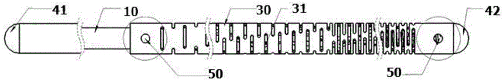
图1是本申请实施例提供的微导丝整体结构示意图;Fig. 1 is a schematic diagram of the overall structure of the micro guide wire provided by the embodiment of the present application;
图2是本申请实施例提供的海波管局部剖视图;Fig. 2 is a partial cross-sectional view of the hypotube provided by the embodiment of the present application;
图3是本申请实施例提供的近端焊接结构示意图;Fig. 3 is a schematic diagram of a proximal welding structure provided by an embodiment of the present application;
图4是本申请实施例提供的远端焊接结构示意图;Fig. 4 is a schematic diagram of the distal welding structure provided by the embodiment of the present application;
图中附图标记的含义:10-芯丝,20-显影元件,30-海波管,31-条形槽,41-近端热胶头,42-远端热胶头,50-填充孔。The meanings of reference signs in the figure: 10-core wire, 20-developing element, 30-hypotube, 31-strip groove, 41-proximal thermal glue tip, 42-distal thermal glue tip, 50-filling hole .
具体实施方式Detailed ways
为使得本申请的申请目的、特征、优点能够更加的明显和易懂,下面将结合本申请实施例中的附图,对本申请实施例中的技术方案进行清楚、完整地描述,显然,下面所描述的实施例仅仅是本申请一部分实施例,而非全部的实施例。基于本申请中的实施例,本领域普通技术人员在没有做出创造性劳动前提下所获得的所有其它实施例,都属于本申请保护的范围。In order to make the purpose, features, and advantages of the application more obvious and understandable, the technical solutions in the embodiments of the application will be clearly and completely described below in conjunction with the drawings in the embodiments of the application. Obviously, the following The described embodiments are only some of the embodiments of the present application, but not all of them. Based on the embodiments in this application, all other embodiments obtained by persons of ordinary skill in the art without making creative efforts belong to the scope of protection of this application.
下面结合附图和具体实施例,进一步阐明本发明。The present invention will be further explained below in conjunction with the accompanying drawings and specific embodiments.
在本申请的描述中,需要理解的是,术语“上”、“下”、“顶”、“底”、“内”、“外”等指示的方位或位置关系为基于附图所示的方位或位置关系,仅是为了便于描述本申请和简化描述,而不是指示或暗示所指的装置或元件必须具有特定的方位、以特定的方位构造和操作,因此不能理解为对本申请的限制。In the description of the present application, it should be understood that the orientation or positional relationship indicated by the terms "upper", "lower", "top", "bottom", "inner", "outer" etc. Orientation or positional relationship is only for the convenience of describing the present application and simplifying the description, and does not indicate or imply that the referred device or element must have a specific orientation, be constructed and operated in a specific orientation, and thus should not be construed as limiting the present application.
本申请涉及医疗血管取栓中的微导丝,该微导丝的芯丝10远端较细以增强柔韧性,近端较粗以便于有效受力被推进人体血管,外部海波管30自身具有传递和通过性,该特性使导丝移动更加灵活。This application relates to a micro-guide wire in medical blood vessel thrombectomy. The
如图1所示,本申请的微导丝完整结构包括近端热胶头41、芯丝10、海波管30、显影弹簧、远端热胶头42。靠近操作人员操作的一端记为近端,背离操作人员操作的一端记为远端。As shown in FIG. 1 , the complete structure of the micro guide wire of the present application includes a proximal
整个芯丝10作为微导丝的主要结构,由多段端面尺寸不同的结构组成,整个芯丝10的直径以逐步减小的趋势由近端向远端延展,这样所形成的芯丝10在近端的断面尺寸较大,芯丝10较硬,靠近远端的芯丝10端面尺寸较小,硬度较小,该设计的目的在于手术的过程中,远端芯丝10最先进入人体组织,这样可以避免对人体组织造成损伤,近端芯丝10也能有足够的支撑力,推动远端芯丝10沿血管接近病变位置,这样的结构可有效地推进导丝沿人体血管前进,外部海波管30自身具有传递和通过性,该特性使导丝移动更加灵活。医护人员通过手持鞘管倾斜一定角度刺入人体血管,当鞘管与人体血管连通之后,手持导丝的较细端从鞘管的孔内沿鞘管推入人体血管,通过微导丝上的显影设计判断导丝与人体病变的相对位置,直到导丝前端到达病变位置,然后将导管鞘沿微导丝推送到人体病变处,进行后续操作。The
整个芯丝10的近端和远端均利用热胶形成热胶头作为芯丝10两头的保护端,其中近端热胶头41连接芯丝10的较大截面一端,远端热胶头42连接芯丝10的较小截面一端,近端热胶头41与芯丝10外延平滑过渡,远端热胶头42与海波管30外端面平滑过渡。The near end and the far end of the
显影元件20套于芯丝10远端表面上,并由热胶粘连,显影元件20的显影作用在临床操作中有利于判断微导丝与病变部位的相对位置。The developing
作为一个具体的实施例,显影元件20采用表面涂布有显影涂层的弹簧,弹簧的弹性结构有利于增加导丝的灵活性,提高过弯能力。As a specific embodiment, the developing
作为一个具体的实施例,海波管30套在显影元件20的外表面以及芯丝10外表面,具体地,海波管30的远端套在显影元件20的外表面,海波管30远端的端面与远端热胶头42粘连,由于海波管30一定比显影元件20长,因此海波管30的近端是套在芯丝10外表面。As a specific embodiment, the
本申请中,海波管30的近端和远端都是从侧面打孔形成贯通的填充孔50,在填充孔50内涂布填充物之后与海波管30内的芯丝10和显影元件20形成固定结构,填充物自身硬度足够的情况下产生阻止海波管30与显影元件20、芯丝10发生相对位移的作用力。In the present application, both the proximal end and the distal end of the
作为一个具体的实施例,如图3中所示,在海波管30的近端一侧,开有对称的2个焊接孔,如图4中所示,在海波管30的远端一侧,开有对称的2个焊接孔。As a specific embodiment, as shown in Figure 3, two symmetrical welding holes are opened on the proximal side of the
通过激光焊接机补丝的方式从焊接孔将芯丝10、显影弹簧与海波管30进行固定,Fix the
作为一个具体的实施例,填充方式采用焊接,以激光焊接机补丝的方式实现亦或者利用圆柱销的焊接方式。As a specific embodiment, the filling method adopts welding, which is realized by a laser welding machine supplementing wire or using a cylindrical pin welding method.
比如,在图3中,海波管30近端的焊接孔可以直插入圆柱销以使得焊接孔内形成填充物,阻止芯丝10与海波管30之间产生滑动。另一个方案是可以利用激光焊接的方式进行补丝焊接,这样相对来说填充更加饱满,稳固性更强。For example, in FIG. 3 , the welding hole at the proximal end of the
图4中,海波管30远端焊接结构的实施方式也分为两种在远端端面一定距离处开有对称的2个焊接孔,远端焊接结构的实施方式也分为两种:一种通过图4所述的远端的两个焊接孔以圆柱销的焊接方式将海波管30与芯丝10、远端热胶头42的圆柱面、显影弹簧进行轴向焊接,在远端热胶头42形成之后,通过激光焊接机补丝的方式从焊接孔将芯丝10、显影弹簧与海波管30进行固定。另一种是通过图4所述的远端的两个焊接孔将芯丝10、远端热胶头42的圆柱面、显影弹簧进行轴向固定的焊接方式。以上所述独特的焊接方式能够使焊点均匀分布于芯丝10、远端热胶头42的圆柱面、显影弹簧的表面,增加芯丝10、远端热胶头42的圆柱面、显影弹簧与海波管30轴向接触面,使连接更加牢固,由于焊接点在海波管30内部,从而也避免了焊点脱落的问题,并且金属焊接,材料特性稳定,避免与人体组织的粘结,海波管30本身又具有柔顺性和可扭转性,在内部接触面的焊接方式也避免了应力集中现象。In Fig. 4, the embodiment of the welding structure at the far end of the
作为一个具体的实施例,海波管30外表面设有沿海波管30径向开口的条形槽31,如图1所示,条形槽31的分布沿海波管30远端向海波管30近端的延伸方向上,条形槽31错位分布且相邻条形槽31的间距逐步减小,条形槽31本身可以降低海波管30的硬度,且有利于海波管30过弯,考虑到整个芯丝10整的直径变化,其远端的过弯性要求更高,因此在本申请中条形槽31的远端分布的更加密集一些以使得海波管30的过弯能力与远端的芯丝10能够保持一致。As a specific embodiment, the outer surface of the
以上详细描述了本发明的优选实施方式,但是本发明并不限于上述实施方式中的具体细节,在本发明的技术构思范围内,可以对本发明的技术方案进行多种等同变换(如数量、形状、位置等),这些等同变换均属于本发明的保护。Preferred embodiments of the present invention have been described in detail above, but the present invention is not limited to the specific details in the above-mentioned embodiments. Within the scope of the technical concept of the present invention, various equivalent transformations (such as quantity, shape, etc.) can be carried out to the technical solutions of the present invention. , position, etc.), these equivalent transformations all belong to the protection of the present invention.
Claims (6)
Priority Applications (1)
| Application Number | Priority Date | Filing Date | Title |
|---|---|---|---|
| CN202211405177.0A CN115887870A (en) | 2022-11-10 | 2022-11-10 | micro guide wire |
Applications Claiming Priority (1)
| Application Number | Priority Date | Filing Date | Title |
|---|---|---|---|
| CN202211405177.0A CN115887870A (en) | 2022-11-10 | 2022-11-10 | micro guide wire |
Publications (1)
| Publication Number | Publication Date |
|---|---|
| CN115887870A true CN115887870A (en) | 2023-04-04 |
Family
ID=86483378
Family Applications (1)
| Application Number | Title | Priority Date | Filing Date |
|---|---|---|---|
| CN202211405177.0A Pending CN115887870A (en) | 2022-11-10 | 2022-11-10 | micro guide wire |
Country Status (1)
| Country | Link |
|---|---|
| CN (1) | CN115887870A (en) |
Cited By (3)
| Publication number | Priority date | Publication date | Assignee | Title |
|---|---|---|---|---|
| CN117982777A (en) * | 2024-04-03 | 2024-05-07 | 万漉医疗科技(江苏)有限公司 | Guide wire system with sacculus |
| CN119733154A (en) * | 2025-03-05 | 2025-04-01 | 杭州亿科医疗科技有限公司 | Vascular interventional catheters |
| WO2025103434A1 (en) * | 2023-11-16 | 2025-05-22 | 深圳市先健神康医疗有限公司 | Deflectable guide wire |
Citations (9)
| Publication number | Priority date | Publication date | Assignee | Title |
|---|---|---|---|---|
| US20090157050A1 (en) * | 2007-03-29 | 2009-06-18 | Terumo Kabushiki Kaisha | Guide wire |
| CN103328033A (en) * | 2010-11-09 | 2013-09-25 | 奥普森斯公司 | Guidewire with internal pressure sensor |
| CN106794330A (en) * | 2014-09-26 | 2017-05-31 | 泰尔茂株式会社 | guide wire |
| US20190030300A1 (en) * | 2017-07-26 | 2019-01-31 | Heraeus Medical Components Llc | Resilient tip and method |
| JP2020518386A (en) * | 2017-05-05 | 2020-06-25 | Hoya株式会社 | Device and method for endoscopic instrument joints |
| CN211243922U (en) * | 2019-08-29 | 2020-08-14 | 北京泰杰伟业科技有限公司 | Conveying device for conveying peripheral blood vessel self-expanding type stent |
| CN113474034A (en) * | 2019-01-15 | 2021-10-01 | 血管科学有限公司 | Guidewire with core centering mechanism |
| CN114041845A (en) * | 2021-12-10 | 2022-02-15 | 上海拓舜医疗科技有限公司 | Conveying system for spring ring for interventional embolization |
| CN217612447U (en) * | 2022-05-06 | 2022-10-21 | 上海通耀医疗科技有限公司 | Hypotube and peripheral sacculus expansion pipe |
-
2022
- 2022-11-10 CN CN202211405177.0A patent/CN115887870A/en active Pending
Patent Citations (9)
| Publication number | Priority date | Publication date | Assignee | Title |
|---|---|---|---|---|
| US20090157050A1 (en) * | 2007-03-29 | 2009-06-18 | Terumo Kabushiki Kaisha | Guide wire |
| CN103328033A (en) * | 2010-11-09 | 2013-09-25 | 奥普森斯公司 | Guidewire with internal pressure sensor |
| CN106794330A (en) * | 2014-09-26 | 2017-05-31 | 泰尔茂株式会社 | guide wire |
| JP2020518386A (en) * | 2017-05-05 | 2020-06-25 | Hoya株式会社 | Device and method for endoscopic instrument joints |
| US20190030300A1 (en) * | 2017-07-26 | 2019-01-31 | Heraeus Medical Components Llc | Resilient tip and method |
| CN113474034A (en) * | 2019-01-15 | 2021-10-01 | 血管科学有限公司 | Guidewire with core centering mechanism |
| CN211243922U (en) * | 2019-08-29 | 2020-08-14 | 北京泰杰伟业科技有限公司 | Conveying device for conveying peripheral blood vessel self-expanding type stent |
| CN114041845A (en) * | 2021-12-10 | 2022-02-15 | 上海拓舜医疗科技有限公司 | Conveying system for spring ring for interventional embolization |
| CN217612447U (en) * | 2022-05-06 | 2022-10-21 | 上海通耀医疗科技有限公司 | Hypotube and peripheral sacculus expansion pipe |
Cited By (4)
| Publication number | Priority date | Publication date | Assignee | Title |
|---|---|---|---|---|
| WO2025103434A1 (en) * | 2023-11-16 | 2025-05-22 | 深圳市先健神康医疗有限公司 | Deflectable guide wire |
| CN117982777A (en) * | 2024-04-03 | 2024-05-07 | 万漉医疗科技(江苏)有限公司 | Guide wire system with sacculus |
| CN117982777B (en) * | 2024-04-03 | 2024-06-14 | 万漉医疗科技(江苏)有限公司 | Guide wire system with sacculus |
| CN119733154A (en) * | 2025-03-05 | 2025-04-01 | 杭州亿科医疗科技有限公司 | Vascular interventional catheters |
Similar Documents
| Publication | Publication Date | Title |
|---|---|---|
| CN115887870A (en) | micro guide wire | |
| US20200121460A1 (en) | Tissue cutting systems, devices and methods | |
| JP5300734B2 (en) | catheter | |
| JP4674969B2 (en) | Guide catheter | |
| US20140066895A1 (en) | Anatomic device delivery and positioning system and method of use | |
| JP2006223338A (en) | catheter | |
| JP2003508110A (en) | Electrosurgical cutting instruments | |
| JP2012533409A (en) | Intraventricular infusion catheter system with integrated echocardiography capability | |
| WO2017185705A1 (en) | Balloon catheter | |
| CN219847790U (en) | A double balloon dilation catheter | |
| JP3380691B2 (en) | Guide wire | |
| JP2022546513A (en) | Methods and devices for delivering implantable prostheses | |
| JPH11221286A (en) | Medical tube | |
| WO2019042454A1 (en) | Coronary vein guide system and guide method thereof | |
| JP4602049B2 (en) | catheter | |
| JP2006075232A (en) | Wire for removing endovascular foreign body, and medical appliance | |
| CN217365999U (en) | Intravascular cutting device | |
| CN216676051U (en) | Sheath core assembly and delivery instrument | |
| CN118526248A (en) | Tectorial membrane support rupture of membranes device | |
| CN117481776A (en) | Small vessel ablation catheter | |
| CN116173375A (en) | A pre-dilated guide wire | |
| US11364368B2 (en) | Guidewire with an integrated flexible tube | |
| CN221750594U (en) | Intervention finger guide wire assembly and intervention system | |
| JP4209753B2 (en) | Heart left ventricular catheter | |
| CN223054510U (en) | A quick exchange extension catheter |
Legal Events
| Date | Code | Title | Description |
|---|---|---|---|
| PB01 | Publication | ||
| PB01 | Publication | ||
| SE01 | Entry into force of request for substantive examination | ||
| SE01 | Entry into force of request for substantive examination |