[go: up one dir, main page]

CN115868073A - Pouch type secondary battery and battery module - Google Patents

Pouch type secondary battery and battery module Download PDF

Info

Publication number
CN115868073A
CN115868073A CN202180050227.5A CN202180050227A CN115868073A CN 115868073 A CN115868073 A CN 115868073A CN 202180050227 A CN202180050227 A CN 202180050227A CN 115868073 A CN115868073 A CN 115868073A
Authority
CN
China
Prior art keywords
secondary battery
edge
cup
pouch
housing
Prior art date
Legal status (The legal status is an assumption and is not a legal conclusion. Google has not performed a legal analysis and makes no representation as to the accuracy of the status listed.)
Pending
Application number
CN202180050227.5A
Other languages
Chinese (zh)
Inventor
吴世永
河廷玟
金根熙
金炫杋
Current Assignee (The listed assignees may be inaccurate. Google has not performed a legal analysis and makes no representation or warranty as to the accuracy of the list.)
LG Energy Solution Ltd
Original Assignee
LG Energy Solution Ltd
Priority date (The priority date is an assumption and is not a legal conclusion. Google has not performed a legal analysis and makes no representation as to the accuracy of the date listed.)
Filing date
Publication date
Priority claimed from KR1020210074471A external-priority patent/KR102564839B1/en
Application filed by LG Energy Solution Ltd filed Critical LG Energy Solution Ltd
Publication of CN115868073A publication Critical patent/CN115868073A/en
Pending legal-status Critical Current

Links

Images

Classifications

    • CCHEMISTRY; METALLURGY
    • C22METALLURGY; FERROUS OR NON-FERROUS ALLOYS; TREATMENT OF ALLOYS OR NON-FERROUS METALS
    • C22CALLOYS
    • C22C21/00Alloys based on aluminium
    • HELECTRICITY
    • H01ELECTRIC ELEMENTS
    • H01MPROCESSES OR MEANS, e.g. BATTERIES, FOR THE DIRECT CONVERSION OF CHEMICAL ENERGY INTO ELECTRICAL ENERGY
    • H01M50/00Constructional details or processes of manufacture of the non-active parts of electrochemical cells other than fuel cells, e.g. hybrid cells
    • H01M50/10Primary casings; Jackets or wrappings
    • H01M50/102Primary casings; Jackets or wrappings characterised by their shape or physical structure
    • H01M50/105Pouches or flexible bags
    • BPERFORMING OPERATIONS; TRANSPORTING
    • B32LAYERED PRODUCTS
    • B32BLAYERED PRODUCTS, i.e. PRODUCTS BUILT-UP OF STRATA OF FLAT OR NON-FLAT, e.g. CELLULAR OR HONEYCOMB, FORM
    • B32B15/00Layered products comprising a layer of metal
    • B32B15/04Layered products comprising a layer of metal comprising metal as the main or only constituent of a layer, which is next to another layer of the same or of a different material
    • B32B15/08Layered products comprising a layer of metal comprising metal as the main or only constituent of a layer, which is next to another layer of the same or of a different material of synthetic resin
    • B32B15/082Layered products comprising a layer of metal comprising metal as the main or only constituent of a layer, which is next to another layer of the same or of a different material of synthetic resin comprising vinyl resins; comprising acrylic resins
    • BPERFORMING OPERATIONS; TRANSPORTING
    • B32LAYERED PRODUCTS
    • B32BLAYERED PRODUCTS, i.e. PRODUCTS BUILT-UP OF STRATA OF FLAT OR NON-FLAT, e.g. CELLULAR OR HONEYCOMB, FORM
    • B32B15/00Layered products comprising a layer of metal
    • B32B15/04Layered products comprising a layer of metal comprising metal as the main or only constituent of a layer, which is next to another layer of the same or of a different material
    • B32B15/08Layered products comprising a layer of metal comprising metal as the main or only constituent of a layer, which is next to another layer of the same or of a different material of synthetic resin
    • B32B15/085Layered products comprising a layer of metal comprising metal as the main or only constituent of a layer, which is next to another layer of the same or of a different material of synthetic resin comprising polyolefins
    • BPERFORMING OPERATIONS; TRANSPORTING
    • B32LAYERED PRODUCTS
    • B32BLAYERED PRODUCTS, i.e. PRODUCTS BUILT-UP OF STRATA OF FLAT OR NON-FLAT, e.g. CELLULAR OR HONEYCOMB, FORM
    • B32B15/00Layered products comprising a layer of metal
    • B32B15/04Layered products comprising a layer of metal comprising metal as the main or only constituent of a layer, which is next to another layer of the same or of a different material
    • B32B15/08Layered products comprising a layer of metal comprising metal as the main or only constituent of a layer, which is next to another layer of the same or of a different material of synthetic resin
    • B32B15/088Layered products comprising a layer of metal comprising metal as the main or only constituent of a layer, which is next to another layer of the same or of a different material of synthetic resin comprising polyamides
    • BPERFORMING OPERATIONS; TRANSPORTING
    • B32LAYERED PRODUCTS
    • B32BLAYERED PRODUCTS, i.e. PRODUCTS BUILT-UP OF STRATA OF FLAT OR NON-FLAT, e.g. CELLULAR OR HONEYCOMB, FORM
    • B32B15/00Layered products comprising a layer of metal
    • B32B15/04Layered products comprising a layer of metal comprising metal as the main or only constituent of a layer, which is next to another layer of the same or of a different material
    • B32B15/08Layered products comprising a layer of metal comprising metal as the main or only constituent of a layer, which is next to another layer of the same or of a different material of synthetic resin
    • B32B15/09Layered products comprising a layer of metal comprising metal as the main or only constituent of a layer, which is next to another layer of the same or of a different material of synthetic resin comprising polyesters
    • BPERFORMING OPERATIONS; TRANSPORTING
    • B32LAYERED PRODUCTS
    • B32BLAYERED PRODUCTS, i.e. PRODUCTS BUILT-UP OF STRATA OF FLAT OR NON-FLAT, e.g. CELLULAR OR HONEYCOMB, FORM
    • B32B15/00Layered products comprising a layer of metal
    • B32B15/04Layered products comprising a layer of metal comprising metal as the main or only constituent of a layer, which is next to another layer of the same or of a different material
    • B32B15/10Layered products comprising a layer of metal comprising metal as the main or only constituent of a layer, which is next to another layer of the same or of a different material of wood
    • BPERFORMING OPERATIONS; TRANSPORTING
    • B32LAYERED PRODUCTS
    • B32BLAYERED PRODUCTS, i.e. PRODUCTS BUILT-UP OF STRATA OF FLAT OR NON-FLAT, e.g. CELLULAR OR HONEYCOMB, FORM
    • B32B15/00Layered products comprising a layer of metal
    • B32B15/14Layered products comprising a layer of metal next to a fibrous or filamentary layer
    • BPERFORMING OPERATIONS; TRANSPORTING
    • B32LAYERED PRODUCTS
    • B32BLAYERED PRODUCTS, i.e. PRODUCTS BUILT-UP OF STRATA OF FLAT OR NON-FLAT, e.g. CELLULAR OR HONEYCOMB, FORM
    • B32B15/00Layered products comprising a layer of metal
    • B32B15/20Layered products comprising a layer of metal comprising aluminium or copper
    • BPERFORMING OPERATIONS; TRANSPORTING
    • B32LAYERED PRODUCTS
    • B32BLAYERED PRODUCTS, i.e. PRODUCTS BUILT-UP OF STRATA OF FLAT OR NON-FLAT, e.g. CELLULAR OR HONEYCOMB, FORM
    • B32B21/00Layered products comprising a layer of wood, e.g. wood board, veneer, wood particle board
    • B32B21/04Layered products comprising a layer of wood, e.g. wood board, veneer, wood particle board comprising wood as the main or only constituent of a layer, which is next to another layer of the same or of a different material
    • B32B21/042Layered products comprising a layer of wood, e.g. wood board, veneer, wood particle board comprising wood as the main or only constituent of a layer, which is next to another layer of the same or of a different material of wood
    • BPERFORMING OPERATIONS; TRANSPORTING
    • B32LAYERED PRODUCTS
    • B32BLAYERED PRODUCTS, i.e. PRODUCTS BUILT-UP OF STRATA OF FLAT OR NON-FLAT, e.g. CELLULAR OR HONEYCOMB, FORM
    • B32B21/00Layered products comprising a layer of wood, e.g. wood board, veneer, wood particle board
    • B32B21/04Layered products comprising a layer of wood, e.g. wood board, veneer, wood particle board comprising wood as the main or only constituent of a layer, which is next to another layer of the same or of a different material
    • B32B21/08Layered products comprising a layer of wood, e.g. wood board, veneer, wood particle board comprising wood as the main or only constituent of a layer, which is next to another layer of the same or of a different material of synthetic resin
    • BPERFORMING OPERATIONS; TRANSPORTING
    • B32LAYERED PRODUCTS
    • B32BLAYERED PRODUCTS, i.e. PRODUCTS BUILT-UP OF STRATA OF FLAT OR NON-FLAT, e.g. CELLULAR OR HONEYCOMB, FORM
    • B32B27/00Layered products comprising a layer of synthetic resin
    • B32B27/06Layered products comprising a layer of synthetic resin as the main or only constituent of a layer, which is next to another layer of the same or of a different material
    • B32B27/08Layered products comprising a layer of synthetic resin as the main or only constituent of a layer, which is next to another layer of the same or of a different material of synthetic resin
    • BPERFORMING OPERATIONS; TRANSPORTING
    • B32LAYERED PRODUCTS
    • B32BLAYERED PRODUCTS, i.e. PRODUCTS BUILT-UP OF STRATA OF FLAT OR NON-FLAT, e.g. CELLULAR OR HONEYCOMB, FORM
    • B32B27/00Layered products comprising a layer of synthetic resin
    • B32B27/28Layered products comprising a layer of synthetic resin comprising synthetic resins not wholly covered by any one of the sub-groups B32B27/30 - B32B27/42
    • B32B27/281Layered products comprising a layer of synthetic resin comprising synthetic resins not wholly covered by any one of the sub-groups B32B27/30 - B32B27/42 comprising polyimides
    • BPERFORMING OPERATIONS; TRANSPORTING
    • B32LAYERED PRODUCTS
    • B32BLAYERED PRODUCTS, i.e. PRODUCTS BUILT-UP OF STRATA OF FLAT OR NON-FLAT, e.g. CELLULAR OR HONEYCOMB, FORM
    • B32B27/00Layered products comprising a layer of synthetic resin
    • B32B27/30Layered products comprising a layer of synthetic resin comprising vinyl (co)polymers; comprising acrylic (co)polymers
    • B32B27/304Layered products comprising a layer of synthetic resin comprising vinyl (co)polymers; comprising acrylic (co)polymers comprising vinyl halide (co)polymers, e.g. PVC, PVDC, PVF, PVDF
    • BPERFORMING OPERATIONS; TRANSPORTING
    • B32LAYERED PRODUCTS
    • B32BLAYERED PRODUCTS, i.e. PRODUCTS BUILT-UP OF STRATA OF FLAT OR NON-FLAT, e.g. CELLULAR OR HONEYCOMB, FORM
    • B32B27/00Layered products comprising a layer of synthetic resin
    • B32B27/30Layered products comprising a layer of synthetic resin comprising vinyl (co)polymers; comprising acrylic (co)polymers
    • B32B27/308Layered products comprising a layer of synthetic resin comprising vinyl (co)polymers; comprising acrylic (co)polymers comprising acrylic (co)polymers
    • BPERFORMING OPERATIONS; TRANSPORTING
    • B32LAYERED PRODUCTS
    • B32BLAYERED PRODUCTS, i.e. PRODUCTS BUILT-UP OF STRATA OF FLAT OR NON-FLAT, e.g. CELLULAR OR HONEYCOMB, FORM
    • B32B27/00Layered products comprising a layer of synthetic resin
    • B32B27/32Layered products comprising a layer of synthetic resin comprising polyolefins
    • BPERFORMING OPERATIONS; TRANSPORTING
    • B32LAYERED PRODUCTS
    • B32BLAYERED PRODUCTS, i.e. PRODUCTS BUILT-UP OF STRATA OF FLAT OR NON-FLAT, e.g. CELLULAR OR HONEYCOMB, FORM
    • B32B27/00Layered products comprising a layer of synthetic resin
    • B32B27/34Layered products comprising a layer of synthetic resin comprising polyamides
    • BPERFORMING OPERATIONS; TRANSPORTING
    • B32LAYERED PRODUCTS
    • B32BLAYERED PRODUCTS, i.e. PRODUCTS BUILT-UP OF STRATA OF FLAT OR NON-FLAT, e.g. CELLULAR OR HONEYCOMB, FORM
    • B32B27/00Layered products comprising a layer of synthetic resin
    • B32B27/36Layered products comprising a layer of synthetic resin comprising polyesters
    • B32B27/365Layered products comprising a layer of synthetic resin comprising polyesters comprising polycarbonates
    • BPERFORMING OPERATIONS; TRANSPORTING
    • B32LAYERED PRODUCTS
    • B32BLAYERED PRODUCTS, i.e. PRODUCTS BUILT-UP OF STRATA OF FLAT OR NON-FLAT, e.g. CELLULAR OR HONEYCOMB, FORM
    • B32B5/00Layered products characterised by the non- homogeneity or physical structure, i.e. comprising a fibrous, filamentary, particulate or foam layer; Layered products characterised by having a layer differing constitutionally or physically in different parts
    • B32B5/02Layered products characterised by the non- homogeneity or physical structure, i.e. comprising a fibrous, filamentary, particulate or foam layer; Layered products characterised by having a layer differing constitutionally or physically in different parts characterised by structural features of a fibrous or filamentary layer
    • BPERFORMING OPERATIONS; TRANSPORTING
    • B32LAYERED PRODUCTS
    • B32BLAYERED PRODUCTS, i.e. PRODUCTS BUILT-UP OF STRATA OF FLAT OR NON-FLAT, e.g. CELLULAR OR HONEYCOMB, FORM
    • B32B7/00Layered products characterised by the relation between layers; Layered products characterised by the relative orientation of features between layers, or by the relative values of a measurable parameter between layers, i.e. products comprising layers having different physical, chemical or physicochemical properties; Layered products characterised by the interconnection of layers
    • B32B7/02Physical, chemical or physicochemical properties
    • HELECTRICITY
    • H01ELECTRIC ELEMENTS
    • H01MPROCESSES OR MEANS, e.g. BATTERIES, FOR THE DIRECT CONVERSION OF CHEMICAL ENERGY INTO ELECTRICAL ENERGY
    • H01M10/00Secondary cells; Manufacture thereof
    • H01M10/04Construction or manufacture in general
    • HELECTRICITY
    • H01ELECTRIC ELEMENTS
    • H01MPROCESSES OR MEANS, e.g. BATTERIES, FOR THE DIRECT CONVERSION OF CHEMICAL ENERGY INTO ELECTRICAL ENERGY
    • H01M10/00Secondary cells; Manufacture thereof
    • H01M10/60Heating or cooling; Temperature control
    • H01M10/61Types of temperature control
    • H01M10/613Cooling or keeping cold
    • HELECTRICITY
    • H01ELECTRIC ELEMENTS
    • H01MPROCESSES OR MEANS, e.g. BATTERIES, FOR THE DIRECT CONVERSION OF CHEMICAL ENERGY INTO ELECTRICAL ENERGY
    • H01M10/00Secondary cells; Manufacture thereof
    • H01M10/60Heating or cooling; Temperature control
    • H01M10/64Heating or cooling; Temperature control characterised by the shape of the cells
    • H01M10/647Prismatic or flat cells, e.g. pouch cells
    • HELECTRICITY
    • H01ELECTRIC ELEMENTS
    • H01MPROCESSES OR MEANS, e.g. BATTERIES, FOR THE DIRECT CONVERSION OF CHEMICAL ENERGY INTO ELECTRICAL ENERGY
    • H01M10/00Secondary cells; Manufacture thereof
    • H01M10/60Heating or cooling; Temperature control
    • H01M10/65Means for temperature control structurally associated with the cells
    • H01M10/653Means for temperature control structurally associated with the cells characterised by electrically insulating or thermally conductive materials
    • HELECTRICITY
    • H01ELECTRIC ELEMENTS
    • H01MPROCESSES OR MEANS, e.g. BATTERIES, FOR THE DIRECT CONVERSION OF CHEMICAL ENERGY INTO ELECTRICAL ENERGY
    • H01M10/00Secondary cells; Manufacture thereof
    • H01M10/60Heating or cooling; Temperature control
    • H01M10/65Means for temperature control structurally associated with the cells
    • H01M10/655Solid structures for heat exchange or heat conduction
    • H01M10/6554Rods or plates
    • HELECTRICITY
    • H01ELECTRIC ELEMENTS
    • H01MPROCESSES OR MEANS, e.g. BATTERIES, FOR THE DIRECT CONVERSION OF CHEMICAL ENERGY INTO ELECTRICAL ENERGY
    • H01M50/00Constructional details or processes of manufacture of the non-active parts of electrochemical cells other than fuel cells, e.g. hybrid cells
    • H01M50/10Primary casings; Jackets or wrappings
    • H01M50/102Primary casings; Jackets or wrappings characterised by their shape or physical structure
    • H01M50/103Primary casings; Jackets or wrappings characterised by their shape or physical structure prismatic or rectangular
    • HELECTRICITY
    • H01ELECTRIC ELEMENTS
    • H01MPROCESSES OR MEANS, e.g. BATTERIES, FOR THE DIRECT CONVERSION OF CHEMICAL ENERGY INTO ELECTRICAL ENERGY
    • H01M50/00Constructional details or processes of manufacture of the non-active parts of electrochemical cells other than fuel cells, e.g. hybrid cells
    • H01M50/10Primary casings; Jackets or wrappings
    • H01M50/116Primary casings; Jackets or wrappings characterised by the material
    • H01M50/117Inorganic material
    • H01M50/119Metals
    • HELECTRICITY
    • H01ELECTRIC ELEMENTS
    • H01MPROCESSES OR MEANS, e.g. BATTERIES, FOR THE DIRECT CONVERSION OF CHEMICAL ENERGY INTO ELECTRICAL ENERGY
    • H01M50/00Constructional details or processes of manufacture of the non-active parts of electrochemical cells other than fuel cells, e.g. hybrid cells
    • H01M50/10Primary casings; Jackets or wrappings
    • H01M50/116Primary casings; Jackets or wrappings characterised by the material
    • H01M50/121Organic material
    • HELECTRICITY
    • H01ELECTRIC ELEMENTS
    • H01MPROCESSES OR MEANS, e.g. BATTERIES, FOR THE DIRECT CONVERSION OF CHEMICAL ENERGY INTO ELECTRICAL ENERGY
    • H01M50/00Constructional details or processes of manufacture of the non-active parts of electrochemical cells other than fuel cells, e.g. hybrid cells
    • H01M50/10Primary casings; Jackets or wrappings
    • H01M50/116Primary casings; Jackets or wrappings characterised by the material
    • H01M50/124Primary casings; Jackets or wrappings characterised by the material having a layered structure
    • H01M50/126Primary casings; Jackets or wrappings characterised by the material having a layered structure comprising three or more layers
    • H01M50/129Primary casings; Jackets or wrappings characterised by the material having a layered structure comprising three or more layers with two or more layers of only organic material
    • HELECTRICITY
    • H01ELECTRIC ELEMENTS
    • H01MPROCESSES OR MEANS, e.g. BATTERIES, FOR THE DIRECT CONVERSION OF CHEMICAL ENERGY INTO ELECTRICAL ENERGY
    • H01M50/00Constructional details or processes of manufacture of the non-active parts of electrochemical cells other than fuel cells, e.g. hybrid cells
    • H01M50/10Primary casings; Jackets or wrappings
    • H01M50/131Primary casings; Jackets or wrappings characterised by physical properties, e.g. gas permeability, size or heat resistance
    • H01M50/133Thickness
    • HELECTRICITY
    • H01ELECTRIC ELEMENTS
    • H01MPROCESSES OR MEANS, e.g. BATTERIES, FOR THE DIRECT CONVERSION OF CHEMICAL ENERGY INTO ELECTRICAL ENERGY
    • H01M50/00Constructional details or processes of manufacture of the non-active parts of electrochemical cells other than fuel cells, e.g. hybrid cells
    • H01M50/10Primary casings; Jackets or wrappings
    • H01M50/131Primary casings; Jackets or wrappings characterised by physical properties, e.g. gas permeability, size or heat resistance
    • H01M50/136Flexibility or foldability
    • HELECTRICITY
    • H01ELECTRIC ELEMENTS
    • H01MPROCESSES OR MEANS, e.g. BATTERIES, FOR THE DIRECT CONVERSION OF CHEMICAL ENERGY INTO ELECTRICAL ENERGY
    • H01M50/00Constructional details or processes of manufacture of the non-active parts of electrochemical cells other than fuel cells, e.g. hybrid cells
    • H01M50/10Primary casings; Jackets or wrappings
    • H01M50/14Primary casings; Jackets or wrappings for protecting against damage caused by external factors
    • H01M50/141Primary casings; Jackets or wrappings for protecting against damage caused by external factors for protecting against humidity
    • HELECTRICITY
    • H01ELECTRIC ELEMENTS
    • H01MPROCESSES OR MEANS, e.g. BATTERIES, FOR THE DIRECT CONVERSION OF CHEMICAL ENERGY INTO ELECTRICAL ENERGY
    • H01M50/00Constructional details or processes of manufacture of the non-active parts of electrochemical cells other than fuel cells, e.g. hybrid cells
    • H01M50/10Primary casings; Jackets or wrappings
    • H01M50/172Arrangements of electric connectors penetrating the casing
    • H01M50/174Arrangements of electric connectors penetrating the casing adapted for the shape of the cells
    • H01M50/178Arrangements of electric connectors penetrating the casing adapted for the shape of the cells for pouch or flexible bag cells
    • HELECTRICITY
    • H01ELECTRIC ELEMENTS
    • H01MPROCESSES OR MEANS, e.g. BATTERIES, FOR THE DIRECT CONVERSION OF CHEMICAL ENERGY INTO ELECTRICAL ENERGY
    • H01M50/00Constructional details or processes of manufacture of the non-active parts of electrochemical cells other than fuel cells, e.g. hybrid cells
    • H01M50/10Primary casings; Jackets or wrappings
    • H01M50/183Sealing members
    • H01M50/186Sealing members characterised by the disposition of the sealing members
    • HELECTRICITY
    • H01ELECTRIC ELEMENTS
    • H01MPROCESSES OR MEANS, e.g. BATTERIES, FOR THE DIRECT CONVERSION OF CHEMICAL ENERGY INTO ELECTRICAL ENERGY
    • H01M50/00Constructional details or processes of manufacture of the non-active parts of electrochemical cells other than fuel cells, e.g. hybrid cells
    • H01M50/20Mountings; Secondary casings or frames; Racks, modules or packs; Suspension devices; Shock absorbers; Transport or carrying devices; Holders
    • H01M50/202Casings or frames around the primary casing of a single cell or a single battery
    • HELECTRICITY
    • H01ELECTRIC ELEMENTS
    • H01MPROCESSES OR MEANS, e.g. BATTERIES, FOR THE DIRECT CONVERSION OF CHEMICAL ENERGY INTO ELECTRICAL ENERGY
    • H01M50/00Constructional details or processes of manufacture of the non-active parts of electrochemical cells other than fuel cells, e.g. hybrid cells
    • H01M50/50Current conducting connections for cells or batteries
    • H01M50/543Terminals
    • H01M50/547Terminals characterised by the disposition of the terminals on the cells
    • H01M50/548Terminals characterised by the disposition of the terminals on the cells on opposite sides of the cell
    • HELECTRICITY
    • H01ELECTRIC ELEMENTS
    • H01MPROCESSES OR MEANS, e.g. BATTERIES, FOR THE DIRECT CONVERSION OF CHEMICAL ENERGY INTO ELECTRICAL ENERGY
    • H01M50/00Constructional details or processes of manufacture of the non-active parts of electrochemical cells other than fuel cells, e.g. hybrid cells
    • H01M50/50Current conducting connections for cells or batteries
    • H01M50/543Terminals
    • H01M50/547Terminals characterised by the disposition of the terminals on the cells
    • H01M50/55Terminals characterised by the disposition of the terminals on the cells on the same side of the cell
    • HELECTRICITY
    • H01ELECTRIC ELEMENTS
    • H01MPROCESSES OR MEANS, e.g. BATTERIES, FOR THE DIRECT CONVERSION OF CHEMICAL ENERGY INTO ELECTRICAL ENERGY
    • H01M50/00Constructional details or processes of manufacture of the non-active parts of electrochemical cells other than fuel cells, e.g. hybrid cells
    • H01M50/50Current conducting connections for cells or batteries
    • H01M50/543Terminals
    • H01M50/552Terminals characterised by their shape
    • H01M50/553Terminals adapted for prismatic, pouch or rectangular cells
    • H01M50/557Plate-shaped terminals
    • BPERFORMING OPERATIONS; TRANSPORTING
    • B32LAYERED PRODUCTS
    • B32BLAYERED PRODUCTS, i.e. PRODUCTS BUILT-UP OF STRATA OF FLAT OR NON-FLAT, e.g. CELLULAR OR HONEYCOMB, FORM
    • B32B2262/00Composition or structural features of fibres which form a fibrous or filamentary layer or are present as additives
    • B32B2262/10Inorganic fibres
    • B32B2262/101Glass fibres
    • BPERFORMING OPERATIONS; TRANSPORTING
    • B32LAYERED PRODUCTS
    • B32BLAYERED PRODUCTS, i.e. PRODUCTS BUILT-UP OF STRATA OF FLAT OR NON-FLAT, e.g. CELLULAR OR HONEYCOMB, FORM
    • B32B2307/00Properties of the layers or laminate
    • B32B2307/70Other properties
    • B32B2307/724Permeability to gases, adsorption
    • B32B2307/7242Non-permeable
    • B32B2307/7246Water vapor barrier
    • BPERFORMING OPERATIONS; TRANSPORTING
    • B32LAYERED PRODUCTS
    • B32BLAYERED PRODUCTS, i.e. PRODUCTS BUILT-UP OF STRATA OF FLAT OR NON-FLAT, e.g. CELLULAR OR HONEYCOMB, FORM
    • B32B2307/00Properties of the layers or laminate
    • B32B2307/70Other properties
    • B32B2307/732Dimensional properties
    • B32B2307/734Dimensional stability
    • BPERFORMING OPERATIONS; TRANSPORTING
    • B32LAYERED PRODUCTS
    • B32BLAYERED PRODUCTS, i.e. PRODUCTS BUILT-UP OF STRATA OF FLAT OR NON-FLAT, e.g. CELLULAR OR HONEYCOMB, FORM
    • B32B2307/00Properties of the layers or laminate
    • B32B2307/70Other properties
    • B32B2307/732Dimensional properties
    • B32B2307/737Dimensions, e.g. volume or area
    • B32B2307/7375Linear, e.g. length, distance or width
    • B32B2307/7376Thickness
    • BPERFORMING OPERATIONS; TRANSPORTING
    • B32LAYERED PRODUCTS
    • B32BLAYERED PRODUCTS, i.e. PRODUCTS BUILT-UP OF STRATA OF FLAT OR NON-FLAT, e.g. CELLULAR OR HONEYCOMB, FORM
    • B32B2439/00Containers; Receptacles
    • B32B2439/40Closed containers
    • HELECTRICITY
    • H01ELECTRIC ELEMENTS
    • H01MPROCESSES OR MEANS, e.g. BATTERIES, FOR THE DIRECT CONVERSION OF CHEMICAL ENERGY INTO ELECTRICAL ENERGY
    • H01M2220/00Batteries for particular applications
    • H01M2220/30Batteries in portable systems, e.g. mobile phone, laptop
    • YGENERAL TAGGING OF NEW TECHNOLOGICAL DEVELOPMENTS; GENERAL TAGGING OF CROSS-SECTIONAL TECHNOLOGIES SPANNING OVER SEVERAL SECTIONS OF THE IPC; TECHNICAL SUBJECTS COVERED BY FORMER USPC CROSS-REFERENCE ART COLLECTIONS [XRACs] AND DIGESTS
    • Y02TECHNOLOGIES OR APPLICATIONS FOR MITIGATION OR ADAPTATION AGAINST CLIMATE CHANGE
    • Y02EREDUCTION OF GREENHOUSE GAS [GHG] EMISSIONS, RELATED TO ENERGY GENERATION, TRANSMISSION OR DISTRIBUTION
    • Y02E60/00Enabling technologies; Technologies with a potential or indirect contribution to GHG emissions mitigation
    • Y02E60/10Energy storage using batteries

Landscapes

  • Chemical & Material Sciences (AREA)
  • Chemical Kinetics & Catalysis (AREA)
  • Electrochemistry (AREA)
  • General Chemical & Material Sciences (AREA)
  • Engineering & Computer Science (AREA)
  • Manufacturing & Machinery (AREA)
  • Wood Science & Technology (AREA)
  • Life Sciences & Earth Sciences (AREA)
  • Inorganic Chemistry (AREA)
  • Materials Engineering (AREA)
  • Mechanical Engineering (AREA)
  • Metallurgy (AREA)
  • Organic Chemistry (AREA)
  • Sealing Battery Cases Or Jackets (AREA)
  • Secondary Cells (AREA)
  • Battery Mounting, Suspending (AREA)

Abstract

根据本发明的一个实施方案的软包型二次电池包括:电极组件,其中堆叠有电极和隔板;软包型电池壳体,包括被配置为内部容纳电极组件的杯部,其中所述电池壳体包括:第一壳体和第二壳体,其中至少一个包括杯部;折叠部,被配置为将所述第一壳体整体连接到所述第二壳体上;以及蝙蝠耳,从所述折叠部的两端的一部分向外突出,其中所述蝙蝠耳的长度为1.5mm以下。

Figure 202180050227

A pouch type secondary battery according to an embodiment of the present invention includes: an electrode assembly in which electrodes and separators are stacked; a pouch type battery case including a cup portion configured to accommodate the electrode assembly inside, wherein the battery The housing includes: a first housing and a second housing, at least one of which includes a cup; a fold configured to integrally connect the first housing to the second housing; and bat ears from Parts of both ends of the folded portion protrude outward, wherein the length of the bat ears is 1.5 mm or less.

Figure 202180050227

Description

软包型二次电池和电池模块Pouch type secondary battery and battery module

技术领域technical field

相关申请的交叉引用Cross References to Related Applications

本申请要求于2020年8月19日提交的韩国专利申请第10-2020-0104227号和于2021年6月08日提交的韩国专利申请第10-2021-0074471号的优先权的权益,通过引用将它们全部并入本说明书中。This application claims the benefit of priority of Korean Patent Application No. 10-2020-0104227 filed on August 19, 2020 and Korean Patent Application No. 10-2021-0074471 filed on June 08, 2021, by reference All of them are incorporated into this specification.

技术领域technical field

本发明涉及一种软包型二次电池和电池模块,并且更具体地,涉及一种能够提高相对于体积的能量密度并且具有优美的外观的软包型二次电池以及电池模块。The present invention relates to a pouch type secondary battery and battery module, and more particularly, to a pouch type secondary battery and battery module capable of improving energy density with respect to volume and having an elegant appearance.

背景技术Background technique

通常,二次电池包括镍-镉电池、镍-氢电池、锂离子电池和锂离子聚合物电池。这种二次电池正在应用于例如数码相机、P-DVD、MP3P、移动电话、PDA、便携式游戏设备、电动工具、电动自行车等小型产品以及例如电动汽车和混合动力汽车、用于存储剩余电力或可再生能源的储能设备和备用储能设备的需要高功率的大型产品中。Generally, secondary batteries include nickel-cadmium batteries, nickel-hydrogen batteries, lithium-ion batteries, and lithium-ion polymer batteries. Such secondary batteries are being used in small products such as digital cameras, P-DVD, MP3P, mobile phones, PDAs, portable game devices, power tools, electric bicycles, etc., as well as for storing surplus power or Renewable energy storage equipment and backup energy storage equipment in large-scale products that require high power.

通常,为了制造二次电池,首先,将电极活性材料浆料施用到正极集电器和负极集电器上以制造正极和负极。然后,将电极堆叠在隔板的两侧上以形成电极组件。此外,将电极组件容纳在电池壳体中,然后在其中注入电解质后将电池壳体密封。Generally, to manufacture a secondary battery, first, an electrode active material slurry is applied to a cathode current collector and an anode current collector to manufacture a cathode and an anode. Then, electrodes are stacked on both sides of the separator to form an electrode assembly. In addition, the electrode assembly is accommodated in a battery case, and then the battery case is sealed after injecting an electrolyte therein.

根据容纳电极组件的壳体的材料,将这种二次电池分类为软包型二次电池和罐型二次电池。在软包型二次电池中,将电极组件容纳在由柔性聚合物材料制成的软包(pouch)中。此外,在罐型二次电池中,将电极组件容纳在由金属或塑料材料制成的壳体中。Such secondary batteries are classified into pouch-type secondary batteries and can-type secondary batteries according to the material of a case housing the electrode assembly. In a pouch type secondary battery, an electrode assembly is accommodated in a pouch made of a flexible polymer material. Also, in a can type secondary battery, an electrode assembly is housed in a case made of metal or plastic material.

软包作为软包型二次电池的壳体,通过在具有柔性的软包膜(pouchfilm)上进行压制处理形成杯部来制造。此外,当形成杯部时,将电极组件容纳在杯部的容纳空间中,然后,将杯部的侧面密封以制造二次电池。The pouch is a case of a pouch-type secondary battery, and is manufactured by pressing a flexible pouch film to form a cup. Also, when the cup is formed, the electrode assembly is accommodated in the accommodation space of the cup, and then, the sides of the cup are sealed to manufacture a secondary battery.

在压制处理时,通过将软包膜插入如压合机的成型设备中并且通过使用冲头对软包膜施加压力来拉伸软包膜而进行拉伸成型。软包膜作为多个层来提供,并且在软包膜中设置的湿气阻挡层由金属制成。然而,根据现有技术,湿气阻挡层的金属在铝合金中具有大的晶粒尺寸,并且湿气阻挡层具有薄的厚度。因此,可模塑性会劣化。因此,当在软包膜上模制杯部时,在模制深度较深的杯部的同时提高杯部边缘的曲率半径和间隙受到限制。此外,电极组件的体积与杯部的体积之比小,并且在减小蝙蝠耳的尺寸方面受到限制,使得相对于二次电池的体积的能量密度也降低。此外,在整体上制造为尖形形状方面受到限制,因此,二次电池的外观不优美,因此,存在市场性也下降的问题。In the pressing process, stretch molding is performed by inserting the soft film into a forming device such as a press machine and stretching the soft film by applying pressure to the soft film using a punch. The soft envelope is provided as a plurality of layers, and the moisture barrier layer provided in the soft envelope is made of metal. However, according to the prior art, the metal of the moisture barrier layer has a large grain size in the aluminum alloy, and the moisture barrier layer has a thin thickness. Therefore, moldability may be deteriorated. Therefore, when the cup is molded on the soft cover, there is a limit to increasing the radius of curvature and clearance of the edge of the cup while molding a cup having a deep depth. In addition, the ratio of the volume of the electrode assembly to the volume of the cup portion is small, and there is a limit in reducing the size of the bat ear, so that the energy density relative to the volume of the secondary battery is also reduced. In addition, there is a limitation in manufacturing the secondary battery in a pointed shape as a whole, so that the appearance of the secondary battery is not beautiful, and therefore, there is a problem that the marketability is also reduced.

日本专利注册第6022956号作为现有技术文件存在。Japanese Patent Registration No. 6022956 exists as a prior art document.

发明内容Contents of the invention

技术问题technical problem

本发明要实现的一个目的是提供一种软包型二次电池和电池模块,该软包型二次电池能够提高相对于体积的能量密度,具有优美的外观,并且提高市场性。An object to be achieved by the present invention is to provide a pouch type secondary battery capable of increasing energy density relative to volume, having an elegant appearance, and improving marketability, and a battery module.

本发明的目的不限于上述目的,但是本领域技术人员将通过下面的描述清楚地理解本文中未描述的其它目的。The object of the present invention is not limited to the above object, but other objects not described herein will be clearly understood by those skilled in the art through the following description.

技术方案Technical solutions

为了实现上述目的,根据本发明的一个实施方案的软包型二次电池包括:电极组件,其中堆叠有电极和隔板;软包型电池壳体,包括被配置为内部容纳电极组件的杯部,其中所述电池壳体包括:第一壳体和第二壳体,其中至少一个包括杯部;折叠部,被配置为将所述第一壳体整体连接到所述第二壳体;以及蝙蝠耳,从所述折叠部的两端中的每一端的一部分向外突出,其中所述蝙蝠耳的长度为1.5mm以下。In order to achieve the above object, a pouch type secondary battery according to an embodiment of the present invention includes: an electrode assembly in which electrodes and separators are stacked; a pouch type battery case including a cup portion configured to accommodate the electrode assembly inside , wherein the battery case includes: a first case and a second case, at least one of which includes a cup; a fold configured to integrally connect the first case to the second case; and A bat ear protrudes outward from a part of each of both ends of the folded portion, wherein the length of the bat ear is 1.5 mm or less.

此外,所述蝙蝠耳的最外端距离折叠部侧外壁的长度可以为1.5mm以下。In addition, the distance from the outermost end of the bat ear to the outer wall on the side of the folded part may be 1.5 mm or less.

此外,所述折叠部与所述蝙蝠耳的内边缘之间的角度可以大于151度。Additionally, the angle between the fold and the inner edge of the bat ear may be greater than 151 degrees.

此外,所述折叠部可以包括向内凹陷的凹槽。In addition, the folded portion may include an inwardly depressed groove.

此外,所述电池壳体可以包括一对突起,所述突起向外突出并且其间具有凹槽,并且所述凹槽的最内侧部分与所述突起的最外侧部分之间的距离可以为0.8mm以下。In addition, the battery case may include a pair of protrusions protruding outward with a groove therebetween, and a distance between an innermost part of the groove and an outermost part of the protrusion may be 0.8 mm. the following.

此外,所述杯部可以包括多个冲头边缘,所述冲头边缘将被配置为围绕其周边的多个外壁分别连接到底部,并且至少一个冲头边缘可以被倒圆。In addition, the cup portion may include a plurality of punch edges connecting a plurality of outer walls configured around its periphery to the bottom, respectively, and at least one punch edge may be rounded.

此外,所述冲头边缘可以具有对应于所述杯部的深度的1/20至1/6的曲率半径。Also, the punch edge may have a radius of curvature corresponding to 1/20 to 1/6 of the depth of the cup.

此外,所述杯部还可以包括厚度边缘,所述厚度边缘被配置为连接彼此相邻的两个外壁,其中所述厚度边缘可以连接至彼此相邻的两个冲头边缘以形成角部。In addition, the cup portion may further include a thickness edge configured to connect two outer walls adjacent to each other, wherein the thickness edge may be connected to two punch edges adjacent to each other to form a corner.

此外,至少一个角部可以被倒圆,并且该角部的曲率半径可以等于或大于冲头边缘或厚度边缘中的至少一者的曲率半径。Furthermore, at least one corner may be rounded, and the radius of curvature of the corner may be equal to or greater than the radius of curvature of at least one of the punch edge or the thickness edge.

此外,所述第一壳体和所述第二壳体各自可以包括杯部,并且所述软包型电池壳体可以包括在这两个杯部之间形成的桥接部,In addition, each of the first case and the second case may include a cup, and the pouch type battery case may include a bridge formed between the two cups,

其中所述桥接部被倒圆。In this case, the bridges are rounded.

此外,所述杯部的深度可以为6.5mm以上。In addition, the depth of the cup may be 6.5 mm or more.

此外,所述电极组件的表面积可以为15000mm2至100000mm2Also, the electrode assembly may have a surface area of 15000 mm 2 to 100000 mm 2 .

此外,可以通过模制软包膜来制造所述电池壳体,并且软包膜可以包括:密封剂层,由第一聚合物制成并且形成在最内层;表面保护层,由第二聚合物制成并且形成在最外层;以及湿气阻挡层,堆叠在所述表面保护层和所述密封剂层之间,其中所述湿气阻挡层可以形成为厚度为50μm至80μm、粒度为10μm至13μm的铝合金薄膜,并且所述密封剂层的厚度可以为60μm至100μm。In addition, the battery case may be manufactured by molding a soft cover, and the soft cover may include: a sealant layer made of a first polymer and formed in the innermost layer; a surface protection layer made of a second polymer; and formed on the outermost layer; and a moisture barrier layer stacked between the surface protection layer and the sealant layer, wherein the moisture barrier layer may be formed with a thickness of 50 μm to 80 μm and a particle size of An aluminum alloy thin film of 10 μm to 13 μm, and the thickness of the sealant layer may be 60 μm to 100 μm.

此外,所述铝合金薄膜可以包括AA8021铝合金。In addition, the aluminum alloy thin film may include AA8021 aluminum alloy.

此外,所述铝合金薄膜可以包含1.3重量%至1.7重量%的铁和0.2重量%以下的硅。In addition, the aluminum alloy thin film may contain 1.3 wt% to 1.7 wt% of iron and 0.2 wt% or less of silicon.

此外,所述湿气阻挡层的厚度可以为55μm至65μm,并且In addition, the thickness of the moisture barrier layer may be 55 μm to 65 μm, and

所述密封剂层的厚度为75μm至85μm。The thickness of the sealant layer is 75 μm to 85 μm.

此外,所述软包型电池壳体还可以包括拉伸辅助层,所述拉伸辅助层由第三聚合物制成并且堆叠在所述表面保护层和所述湿气阻挡层之间。In addition, the pouch type battery case may further include a stretching auxiliary layer made of a third polymer and stacked between the surface protection layer and the moisture barrier layer.

此外,所述拉伸辅助层的厚度可以为20μm至50μm。In addition, the stretching auxiliary layer may have a thickness of 20 μm to 50 μm.

为了实现上述目的,根据本发明的一个实施方案的软包型二次电池包括:电极组件,其中堆叠有电极和隔板;软包型电池壳体,包括被配置为内部容纳电极组件的杯部,其中所述电池壳体包括:第一壳体和第二壳体,其中至少一个包括杯部;折叠部,被配置为将所述第一壳体整体连接到所述第二壳体上;以及蝙蝠耳,从所述折叠部的两端中的每一端的一部分向外突出,其中所述折叠部与所述蝙蝠耳的内边缘之间的角度大于151度。In order to achieve the above object, a pouch type secondary battery according to an embodiment of the present invention includes: an electrode assembly in which electrodes and separators are stacked; a pouch type battery case including a cup portion configured to accommodate the electrode assembly inside , wherein the battery case includes: a first case and a second case, at least one of which includes a cup; a fold configured to integrally connect the first case to the second case; and a bat ear protruding outwardly from a portion of each of two ends of the fold, wherein an angle between the fold and an inner edge of the bat ear is greater than 151 degrees.

为了实现上述目的,根据本发明的一个实施方案的电池模块包括:电极组件,其中堆叠有电极和隔板;软包型二次电池,容纳在软包型电池壳体中形成的杯部中;以及外壳,其中容纳有二次电池,其中所述电池壳体包括:第一壳体和第二壳体,其中至少一个包括杯部;折叠部,被配置为将所述第一壳体整体连接到所述第二壳体;以及蝙蝠耳,从所述折叠部的两端的每一端的一部分向外突出,其中所述蝙蝠耳的长度为1.5mm以下。To achieve the above object, a battery module according to an embodiment of the present invention includes: an electrode assembly in which electrodes and separators are stacked; a pouch type secondary battery housed in a cup formed in a pouch type battery case; and a case in which a secondary battery is accommodated, wherein the battery case includes: a first case and a second case, at least one of which includes a cup portion; a fold portion configured to integrally connect the first case to the second housing; and bat ears protruding outward from a portion of each of both ends of the folded portion, wherein the bat ears have a length of 1.5 mm or less.

此外,所述折叠部与所述蝙蝠耳的内边缘之间的角度可以大于151度。Additionally, the angle between the fold and the inner edge of the bat ear may be greater than 151 degrees.

此外,所述外壳可以包括冷却板,所述冷却板被配置为冷却所述二次电池。Also, the case may include a cooling plate configured to cool the secondary battery.

此外,所述电池模块还可以包括传热材料,所述传热材料形成在所述冷却板和所述二次电池的折叠部之间。In addition, the battery module may further include a heat transfer material formed between the cooling plate and the folded portion of the secondary battery.

此外,所述传热材料在外壳内的厚度可以为1mm以下。In addition, the thickness of the heat transfer material inside the housing may be less than 1 mm.

为了实现上述目的,根据本发明的一个实施方案的电池模块包括:电极组件,其中堆叠有电极和隔板;软包型二次电池,容纳在软包型电池壳体中形成的杯部中;以及外壳,其中容纳有二次电池,其中所述电池壳体包括:第一壳体和第二壳体,其中至少一个包括杯部;折叠部,被配置为将所述第一壳体整体连接到所述第二壳体;以及蝙蝠耳,从所述折叠部的两端的每一端的一部分向外突出,其中所述折叠部与所述蝙蝠耳的内边缘之间的角度大于151度。To achieve the above object, a battery module according to an embodiment of the present invention includes: an electrode assembly in which electrodes and separators are stacked; a pouch type secondary battery housed in a cup formed in a pouch type battery case; and a case in which a secondary battery is accommodated, wherein the battery case includes: a first case and a second case, at least one of which includes a cup portion; a fold portion configured to integrally connect the first case to the second housing; and a bat ear protruding outwardly from a portion of each of two ends of the fold, wherein an angle between the fold and an inner edge of the bat ear is greater than 151 degrees.

实施方案的其它细节包括在详细的描述和附图中。Additional details of the embodiments are included in the detailed description and drawings.

有益效果Beneficial effect

根据本发明的实施方案,具有至少以下效果。According to an embodiment of the present invention, there are at least the following effects.

由于可以减小蝙蝠耳的尺寸,因此,相对于二次电池的体积的能量密度可以增加。Since the size of the bat ear can be reduced, the energy density relative to the volume of the secondary battery can be increased.

此外,由于杯部的外壁和电极组件之间的空间缩小,因此,相对于二次电池的体积的能量密度可以增加。In addition, since the space between the outer wall of the cup portion and the electrode assembly is reduced, energy density with respect to the volume of the secondary battery may increase.

此外,由于电极组件和热润滑脂之间的距离也缩短了,因此可以进一步提高冷却效率。In addition, since the distance between the electrode assembly and thermal grease is also shortened, cooling efficiency can be further improved.

此外,由于软包型电池壳体和软包型二次电池各自整体上具有尖形形状,因此二次电池的外观可以优美,并且可以提高市场性。In addition, since the pouch-type battery case and the pouch-type secondary battery each have a pointed shape as a whole, the appearance of the secondary battery can be elegant, and marketability can be improved.

本发明的效果不限于上述的描述,因此,本说明书中涉及更多不同的效果。The effects of the present invention are not limited to the above description, and therefore, more various effects are involved in this specification.

附图说明Description of drawings

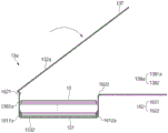
图1是根据本发明的一个实施方案的二次电池1的组装图;FIG. 1 is an assembly diagram of a secondary battery 1 according to an embodiment of the present invention;

图2是根据本发明的一个实施方案的软包膜135的截面图;Figure 2 is a cross-sectional view of a soft envelope 135 according to one embodiment of the present invention;

图3是示出合金编号为AA8079的铝合金和合金编号为AA8021的铝合金的铁和硅的含量的图;3 is a graph showing the iron and silicon content of an aluminum alloy having alloy number AA8079 and an aluminum alloy having alloy number AA8021;

图4是示出根据合金编号为AA8079的铝合金和合金编号为AA8021的铝合金的铁和硅的含量的拉伸强度、伸长率和粒度的曲线图。4 is a graph showing tensile strength, elongation, and grain size according to the iron and silicon content of an aluminum alloy having alloy number AA8079 and an aluminum alloy having alloy number AA8021.

图5是合金编号为AA8079的铝合金和合金编号为AA8021的铝合金的晶粒的放大SEM照片;Figure 5 is an enlarged SEM photo of the grains of the aluminum alloy with the alloy number AA8079 and the aluminum alloy with the alloy number AA8021;

图6是根据本发明的一个实施方案的成型设备2的示意图。Fig. 6 is a schematic diagram of a molding apparatus 2 according to an embodiment of the present invention.

图7是根据现有技术的杯部333和桥接部336的放大示意图。FIG. 7 is an enlarged schematic view of the cup portion 333 and the bridge portion 336 according to the prior art.

图8是根据本发明的一个实施方案的杯部333和桥接部336的放大示意图。FIG. 8 is an enlarged schematic view of the cup portion 333 and the bridge portion 336 according to one embodiment of the present invention.

图9是根据本发明的一个实施方案的杯部133和脱气部137的放大示意图。FIG. 9 is an enlarged schematic view of the cup portion 133 and the degassing portion 137 according to an embodiment of the present invention.

图10是示出根据本发明的一个实施方案的将电极组件10容纳在杯部133中的状态的示意性顶视图。FIG. 10 is a schematic top view showing a state in which the electrode assembly 10 is accommodated in the cup portion 133 according to one embodiment of the present invention.

图11是根据现有技术的角部364的示意图。Figure 11 is a schematic illustration of a corner 364 according to the prior art.

图12是根据本发明的一个实施方案的角部164的示意图。Figure 12 is a schematic illustration of corner 164 according to one embodiment of the present invention.

图13是示出根据本发明的一个实施方案的电池壳体13折叠的状态的示意图。FIG. 13 is a schematic diagram showing a state in which the battery case 13 according to one embodiment of the present invention is folded.

图14是示出根据本发明的一个实施方案的电池壳体13折叠的状态的示意图。FIG. 14 is a schematic diagram showing a state in which the battery case 13 according to one embodiment of the present invention is folded.

图15是根据本发明的一个实施方案的电池壳体13中形成的凹槽1391的放大图。FIG. 15 is an enlarged view of a groove 1391 formed in the battery case 13 according to an embodiment of the present invention.

图16是根据本发明的另一实施方案的杯部133和模压边缘1621的放大示意图。FIG. 16 is an enlarged schematic view of a cup portion 133 and a molded rim 1621 according to another embodiment of the present invention.

图17是示出根据本发明的另一实施方案的电池壳体13a折叠的状态的示意图。FIG. 17 is a schematic view showing a folded state of a battery case 13a according to another embodiment of the present invention.

图18是示出根据本发明的另一实施方案的电池壳体13a折叠的状态的示意图。FIG. 18 is a schematic diagram showing a state in which a battery case 13a according to another embodiment of the present invention is folded.

图19是根据本发明的另一实施方案的电池壳体13中形成的凹槽1391a的放大图。FIG. 19 is an enlarged view of a groove 1391a formed in a battery case 13 according to another embodiment of the present invention.

图20是示出根据现有技术的电池壳体33的脱气部337切割之前的状态的示意性顶视图。FIG. 20 is a schematic top view showing the state before the degassing portion 337 of the battery case 33 according to the prior art is cut.

图21是示出根据本发明的一个实施方案的电池壳体13的脱气部137切割之前的状态的示意性顶视图。FIG. 21 is a schematic top view showing a state before the degassing portion 137 of the battery case 13 is cut according to an embodiment of the present invention.

图22是根据本发明的一个实施方案的检查装置4的方框图。Fig. 22 is a block diagram of an inspection device 4 according to an embodiment of the present invention.

图23是示出根据本发明的一个实施方案的电池壳体13的脱气部被切割而完成二次电池1的制造的状态的示意图。23 is a schematic diagram showing a state in which the degassed portion of the battery case 13 is cut to complete the manufacture of the secondary battery 1 according to one embodiment of the present invention.

图24是示出根据现有技术的侧面334折叠的状态的示意性侧视图。FIG. 24 is a schematic side view showing a state in which the side 334 is folded according to the prior art.

图25是示出根据现有技术的侧面334折叠的状态的示意性顶视图。FIG. 25 is a schematic top view showing a state in which the sides 334 are folded according to the prior art.

图26是示出根据本发明的一个实施方案的侧面134折叠的状态的示意性侧视图。Fig. 26 is a schematic side view showing a state in which the sides 134 are folded according to one embodiment of the present invention.

图27是根据本发明的一个实施方案的电池模块5的示意图。Fig. 27 is a schematic diagram of a battery module 5 according to an embodiment of the present invention.

图28是示出根据现有技术的电池模块5的外壳51中容纳二次电池3的状态的放大前视图。28 is an enlarged front view showing a state in which the secondary battery 3 is housed in the case 51 of the battery module 5 according to the related art.

图29是示出根据现有技术的电池模块5的外壳51中容纳二次电池3的状态的放大侧视图。29 is an enlarged side view showing a state in which the secondary battery 3 is housed in the case 51 of the battery module 5 according to the related art.

图30是示出根据本发明的一个实施方案的电池模块的外壳51中容纳二次电池1的状态的放大前视图。FIG. 30 is an enlarged front view showing a state in which the secondary battery 1 is accommodated in the case 51 of the battery module according to one embodiment of the present invention.

图31是示出根据本发明的一个实施方案的电池模块的外壳51中容纳二次电池1的状态的放大侧视图。31 is an enlarged side view showing a state in which a secondary battery 1 is accommodated in a case 51 of a battery module according to an embodiment of the present invention.

具体实施方式Detailed ways

将通过参考附图描述的以下实施方案来阐明本发明的优点和特征以及它们的实现方法。然而,本发明可以以不同的形式实施,并且不应被解释为限于本文所列的实施方案。相反,提供这些实施方案以使本公开将是彻底和完整的,并且将向本领域技术人员充分传达本发明的范围。此外,本发明仅由权利要求的范围限定。全文中相同的附图标记是指相同的元件。Advantages and features of the present invention and methods of achieving them will be clarified by the following embodiments described with reference to the accompanying drawings. However, this invention may be embodied in different forms and should not be construed as limited to the embodiments set forth herein. Rather, these embodiments are provided so that this disclosure will be thorough and complete, and will fully convey the scope of the invention to those skilled in the art. Furthermore, the present invention is limited only by the scope of the claims. Like reference numerals refer to like elements throughout.

除非本发明中使用的术语定义不同,否则本文中使用的所有术语(包括技术术语和科学术语)具有本领域技术人员通常理解的相同含义。此外,除非在说明书中明确定义,否则常用词典中定义的术语不会理想化或过度解释为具有正式的含义。Unless the definitions of terms used in the present invention are different, all terms (including technical terms and scientific terms) used herein have the same meaning as commonly understood by those skilled in the art. Furthermore, terms defined in commonly used dictionaries are not idealized or over-interpreted to have official meanings unless explicitly defined in the specification.

在下面的描述中,技术术语在不限制本发明的同时仅用于解释特定的示例性实施方案。在本说明书中,除非特别提及,否则单数形式的术语也可以包括复数形式。“包括(包含)”和/或“包括(含有)”的含义不排除除所述部件之外的其它部件。In the following description, technical terms are merely used to explain specific exemplary embodiments while not limiting the present invention. In this specification, unless specifically mentioned, the terms of singular form may also include plural forms. The meaning of "comprises" and/or "comprises" does not exclude other elements than those stated.

下文中,将参照附图详细地描述优选的实施方案。Hereinafter, preferred embodiments will be described in detail with reference to the accompanying drawings.

图1是根据本发明的一个实施方案的二次电池1的组装图。FIG. 1 is an assembly view of a secondary battery 1 according to an embodiment of the present invention.

根据本发明的一个实施方案,由于软包膜135的拉伸强度和拉伸率可以提高,因此在模制软包膜135来制造软包型电池壳体13时,可以提高韧性从而改善模压性能。According to one embodiment of the present invention, since the tensile strength and elongation rate of the soft coating film 135 can be increased, when the soft coating film 135 is molded to manufacture the soft pack type battery case 13, the toughness can be improved so as to improve the molding performance. .

为此,根据本发明的一个实施方案的软包膜135包括:密封剂层1351(见图2),由第一聚合物制成并形成在最内层;表面保护层1353(见图2),由第二聚合物制成并形成在最外层;以及湿气(或气体)阻挡层1352(参见图2),堆叠在表面保护层1353和密封剂层1351之间。湿气阻挡层1352可以形成为厚度为50μm至80μm、粒度为10μm至13μm的铝合金薄膜,密封剂层1351的厚度可以为60μm至100μm。特别地,湿气阻挡层1352的厚度可以为55μm至65μm,密封剂层1351的厚度可以为75μm至85μm。To this end, the soft envelope 135 according to one embodiment of the present invention includes: a sealant layer 1351 (see FIG. 2 ), made of a first polymer and formed in the innermost layer; a surface protection layer 1353 (see FIG. 2 ). , made of the second polymer and formed in the outermost layer; and a moisture (or gas) barrier layer 1352 (see FIG. 2 ), stacked between the surface protection layer 1353 and the sealant layer 1351. The moisture barrier layer 1352 may be formed as an aluminum alloy thin film with a thickness of 50-80 μm and a grain size of 10-13 μm, and the thickness of the sealant layer 1351 may be 60-100 μm. In particular, the moisture barrier layer 1352 may have a thickness of 55 μm to 65 μm, and the sealant layer 1351 may have a thickness of 75 μm to 85 μm.

电极组件10通过交替堆叠电极101(见图8)和隔板102(见图8)形成。首先,将其中电极活性材料、粘合剂和增塑剂相互混合的浆料施用到正极集电器和负极集电器上来制造电极101,例如正极和负极。然后,在电极101之间堆叠各自的隔板102以形成电极组件10,将电极组件10插入电池壳体13中,并且注入电解质以密封电池壳体13。The electrode assembly 10 is formed by alternately stacking electrodes 101 (see FIG. 8 ) and separators 102 (see FIG. 8 ). First, a slurry in which an electrode active material, a binder, and a plasticizer are mixed with each other is applied to a positive electrode current collector and a negative electrode current collector to manufacture the electrode 101 such as a positive electrode and a negative electrode. Then, the respective separators 102 are stacked between the electrodes 101 to form the electrode assembly 10 , the electrode assembly 10 is inserted into the battery case 13 , and electrolyte is injected to seal the battery case 13 .

电极组件10的表面积可以为15000mm2至100000mm2,通过将全长乘以全宽获得。特别地,电极组件10的全宽可以是60mm以上。此外,电极组件10在堆叠方向上的厚度可以为6mm至20mm。因此,与一般小型电池相比,根据本发明的一个实施方案的电极组件10可以提供大的电池容量。The surface area of the electrode assembly 10 may be 15000 mm 2 to 100000 mm 2 obtained by multiplying the overall length by the overall width. In particular, the entire width of the electrode assembly 10 may be 60 mm or more. In addition, the thickness of the electrode assembly 10 in the stacking direction may be 6 mm to 20 mm. Therefore, the electrode assembly 10 according to one embodiment of the present invention can provide a large battery capacity compared with a general small battery.

具体而言,电极组件10包括例如正极和负极的两种类型的电极101和插入电极101之间以使电极101彼此绝缘的隔板102。电极组件10可以是堆式、果冻卷式、堆叠和折叠式等。这两种类型的电极101,即正极和负极各自具有其中活性材料浆料施用到具有金属箔或金属网形状的电极集电器上的结构。活性材料浆料通常可以通过在添加溶剂的状态下搅拌粒状活性材料、导体等形成。溶剂可以在后续过程中除去。Specifically, the electrode assembly 10 includes two types of electrodes 101 such as a positive electrode and a negative electrode, and a separator 102 interposed between the electrodes 101 to insulate the electrodes 101 from each other. The electrode assembly 10 may be a stack type, a jelly-roll type, a stacked and folded type, or the like. These two types of electrodes 101 , positive and negative electrodes each have a structure in which an active material slurry is applied to an electrode collector having a metal foil or metal mesh shape. The active material slurry can generally be formed by stirring granular active materials, conductors, and the like in a state where a solvent is added. The solvent can be removed in a subsequent process.

如图1所示,电极组件10包括电极片11。电极片11分别连接到电极组件10的正极和负极上以从电极组件10向外突出,从而在电极组件10的内部和外部之间提供一条电子移动的路径。电极组件10的电极集电器由涂覆有电极活性材料的部分和其上未涂覆电极活性材料的远端即未涂覆部分构成。此外,每个电极片11可以通过切割未涂覆部分或通过超声波焊接将单独的导电构件与未涂覆部分连接来形成。如图1所示,电极片11可以沿电极组件10的不同方向的每个方向突出,但不限于此。例如,电极片可以沿各种方向突出,例如,从一侧以同一方向彼此平行地突出。As shown in FIG. 1 , the electrode assembly 10 includes an electrode sheet 11 . The electrode tabs 11 are respectively connected to positive and negative electrodes of the electrode assembly 10 to protrude outward from the electrode assembly 10 , thereby providing a path for electron movement between the inside and outside of the electrode assembly 10 . The electrode collector of the electrode assembly 10 is composed of a portion coated with an electrode active material and a distal end, ie, an uncoated portion, on which the electrode active material is not coated. In addition, each electrode tab 11 may be formed by cutting an uncoated portion or connecting a separate conductive member to the uncoated portion by ultrasonic welding. As shown in FIG. 1 , the electrode sheet 11 may protrude in each of different directions of the electrode assembly 10 , but is not limited thereto. For example, the electrode tabs may protrude in various directions, for example, protrude from one side in parallel to each other in the same direction.

在电极组件10中,通过点焊将向二次电池1的外部供电的电极引线12连接到电极片11上。此外,电极引线12的一部分被绝缘部14包围。绝缘部14可以布置为限于将电池壳体13的第一壳体131和第二壳体132热熔合的侧面134处,以使电极引线12接合到电池壳体13上。此外,可以防止从电极组件10产生的电通过电极引线12流向电池壳体13,并且可以保持电池壳体13密封。因此,绝缘部14可以由没有导电性,即不导电的非导体制成。通常,虽然容易粘附到电极引线12并且具有相对薄的厚度的绝缘胶带主要用作绝缘部14,但是本发明不限于此。例如,可以使用各种构件作为绝缘部14,只要这些构件能够将电极引线12绝缘即可。In the electrode assembly 10 , electrode leads 12 for supplying power to the outside of the secondary battery 1 are connected to the electrode tabs 11 by spot welding. In addition, a part of the electrode lead 12 is surrounded by the insulating part 14 . The insulating part 14 may be arranged limited to the side 134 thermally fusing the first case 131 and the second case 132 of the battery case 13 to bond the electrode lead 12 to the battery case 13 . In addition, electricity generated from the electrode assembly 10 can be prevented from flowing to the battery case 13 through the electrode lead 12, and the battery case 13 can be kept sealed. Therefore, the insulating part 14 may be made of a non-conductor that has no conductivity, ie is not conductive. Generally, although an insulating tape that is easily adhered to the electrode lead 12 and has a relatively thin thickness is mainly used as the insulating portion 14, the present invention is not limited thereto. For example, various members can be used as the insulating portion 14 as long as they can insulate the electrode lead 12 .

电极引线12的一端连接到电极片11上,并且电极引线12的另一端突出到电池壳体13的外部。即,电极引线12包括一端连接到正极片111上以在正极片111突出的方向上延伸的正极引线121和一端连接到负极片112上以在负极片112突出的方向上延伸的负极引线122。另一方面,如图1所示,正极引线121和负极引线122的另一端全部突出到电池壳体13的外部。结果,在电极组件10中产生的电可以供应到外部。此外,由于正极片111和负极片112各自形成为在不同方向上突出,因此正极引线121和负极引线122各自可以在不同方向上延伸。One end of the electrode lead 12 is connected to the electrode sheet 11 , and the other end of the electrode lead 12 protrudes to the outside of the battery case 13 . That is, the electrode lead 12 includes a positive lead 121 connected at one end to the positive tab 111 to extend in the direction in which the positive tab 111 protrudes, and a negative lead 122 connected to the negative tab 112 at one end to extend in the direction in which the negative tab 112 protrudes. On the other hand, as shown in FIG. 1 , the other ends of the positive electrode lead 121 and the negative electrode lead 122 all protrude to the outside of the battery case 13 . As a result, electricity generated in the electrode assembly 10 can be supplied to the outside. In addition, since each of the positive electrode tab 111 and the negative electrode tab 112 is formed to protrude in different directions, each of the positive electrode lead 121 and the negative electrode lead 122 may extend in different directions.

正极引线121和负极引线122可以由彼此不同的材料制成。即,正极引线121可以由与正极集电器相同的材料,即铝(Al)材料制成,负极引线122可以由与负极集电器相同的材料,即铜(Cu)材料或涂覆有镍(Ni)的铜材料制成。此外,突出到电池壳体13的外部的电极引线12的部分可以设置为端子部并且电连接到外端。The cathode lead 121 and the anode lead 122 may be made of different materials from each other. That is, the positive electrode lead 121 may be made of the same material as the positive electrode current collector, that is, aluminum (Al), and the negative electrode lead 122 may be made of the same material as the negative electrode current collector, that is, copper (Cu) material or coated with nickel (Ni ) made of copper material. In addition, a portion of the electrode lead 12 protruding to the outside of the battery case 13 may be provided as a terminal portion and electrically connected to the outer end.

电池壳体13是通过模制柔性材料制造并在其中容纳电极组件10的软包。下文中,将描述电池壳体13是软包的情况。当通过使用冲头22(参见图6)等将具有柔韧性的软包膜135拉伸成型时,将软包膜135的一部分拉伸以形成包括口软包状的容纳空间1331的杯部133,从而制造电池壳体13。The battery case 13 is a soft case manufactured by molding a flexible material and accommodates the electrode assembly 10 therein. Hereinafter, the case where the battery case 13 is a soft case will be described. When stretching the flexible soft coating 135 by using a punch 22 (see FIG. 6 ) or the like, a part of the soft coating 135 is stretched to form the cup portion 133 including a soft bag-shaped accommodation space 1331. , thereby manufacturing the battery case 13 .

电池壳体13容纳电极组件10,使得电极引线12的一部分露出,然后密封。如图1所示,电池壳体13包括第一壳体131和第二壳体132。可以在第一壳体131中设置其中形成有杯部133以容纳电极组件10的容纳空间1331,并且第二壳体132可以覆盖容纳空间1331的上面,使得电极组件10不会脱离到电池壳体13的外部。如图1所示,第一壳体131的一侧和第二壳体132的一侧可以彼此连接。然而,本发明不限于此。例如,第一壳体131和第二壳体132可以单独制造为彼此分离。The battery case 13 accommodates the electrode assembly 10 such that a part of the electrode lead 12 is exposed, and is then sealed. As shown in FIG. 1 , the battery case 13 includes a first case 131 and a second case 132 . An accommodating space 1331 in which a cup portion 133 is formed to accommodate the electrode assembly 10 may be provided in the first case 131, and the second case 132 may cover the upper side of the accommodating space 1331 so that the electrode assembly 10 does not detach from the battery case. 13 exterior. As shown in FIG. 1 , one side of the first case 131 and one side of the second case 132 may be connected to each other. However, the present invention is not limited thereto. For example, the first case 131 and the second case 132 may be separately manufactured to be separated from each other.

当在软包膜135中模制杯部133时,可以在一个软包膜135中只形成一个杯部133,但是本发明不限于此。例如,可以在一个软包膜135中拉伸成型为彼此相邻的两个杯部。然后,如图1所示,分别在第一壳体131和第二壳体132中形成杯部133。这里,在第一壳体131和第二壳体132中分别形成的杯部133各自可以具有相同的深度D,但是不限于此,并且可以具有不同的深度D。When the cup part 133 is molded in the soft cover 135, only one cup part 133 may be formed in one soft cover 135, but the present invention is not limited thereto. For example, two cups adjacent to each other may be stretch formed in one soft envelope 135 . Then, as shown in FIG. 1 , cup portions 133 are formed in the first housing 131 and the second housing 132 , respectively. Here, the cup portions 133 respectively formed in the first case 131 and the second case 132 may each have the same depth D, but are not limited thereto, and may have different depths D. Referring to FIG.

根据本发明的一个实施方案,杯部133的深度D可以为3mm以上,尤其是6.5mm以上。因此,根据本发明的一个实施方案的杯部133可以容纳比常规小型电池具有更大的电极容量的电极组件10。According to an embodiment of the present invention, the depth D of the cup portion 133 may be greater than 3 mm, especially greater than 6.5 mm. Therefore, the cup portion 133 according to one embodiment of the present invention can accommodate the electrode assembly 10 having a larger electrode capacity than conventional small batteries.

在第一壳体131的杯部133中设置的容纳空间1331中容纳电极组件10后,电池壳体13可以相对于在电池壳体13中的两个杯部133之间形成的桥接部136折叠,以使两个杯部133彼此面对。然后,第二壳体132的杯部133也从其上面容纳电极组件10。因此,由于两个杯部133容纳一个电极组件10,因此当与设置一个杯部133的情况相比,可以容纳具有更厚的厚度的电极组件10。此外,由于第一壳体131和第二壳体132通过折叠电池壳体13而彼此整体连接,因此可以减少后面进行密封处理时要密封的侧面134的数量。因此,可以提高处理速率,并且可以减少密封处理的数量。After accommodating the electrode assembly 10 in the accommodation space 1331 provided in the cup portion 133 of the first case 131 , the battery case 13 can be folded relative to the bridge portion 136 formed between the two cup portions 133 in the battery case 13 , so that the two cup portions 133 face each other. Then, the cup portion 133 of the second case 132 also accommodates the electrode assembly 10 from above. Therefore, since two cups 133 accommodate one electrode assembly 10 , an electrode assembly 10 having a thicker thickness can be accommodated when compared with a case where one cup 133 is provided. In addition, since the first case 131 and the second case 132 are integrally connected to each other by folding the battery case 13, the number of sides 134 to be sealed in a later sealing process can be reduced. Therefore, the processing rate can be increased, and the number of sealing processes can be reduced.

电池壳体13可以包括其中设置有容纳电极组件10的容纳空间1331的杯部133以及形成在杯部133的侧部以通过脱气孔H排出在杯部133中产生的气体的脱气部137。当将电极组件10容纳在电池壳体13的杯部133中,并且注入电解质,然后进行活化过程时,在电池壳体13的内部产生气体,因此进行将气体排出到外部的脱气过程。脱气部137的详细说明将在后面描述。The battery case 13 may include a cup portion 133 in which an accommodation space 1331 accommodating the electrode assembly 10 is disposed, and a degassing portion 137 formed at a side of the cup portion 133 to discharge gas generated in the cup portion 133 through a degassing hole H. When the electrode assembly 10 is accommodated in the cup portion 133 of the battery case 13, and electrolyte is injected, and then an activation process is performed, gas is generated inside the battery case 13, and thus a degassing process of exhausting the gas to the outside is performed. Details of the degassing unit 137 will be described later.

当电极引线12连接到电极组件10的电极片11上,并且在电极引线12的一部分上形成绝缘部14时,将电极组件10容纳在第一壳体131的杯部133中设置的容纳空间1331中,并且第二壳体132从上面覆盖容纳空间。此外,将电解质注入到容纳空间中,并且密封延伸至第一壳体131和第二壳体132的各自的杯部133的外部的侧面134。电解质可以移动在二次电池1的充电和放电过程中由电极101的电化学反应产生的锂离子。电解质可以包括非水性的有机电解液(即锂盐和高纯度有机溶剂的混合物),或者使用聚合物电解质的聚合物。此外,电解质可以包括硫化物类、氧化物类或聚合物类固体电解质,并且固体电解质可以具有易受外力变形的柔韧性。软包型二次电池1可以通过上述方法制造。When the electrode lead 12 is connected to the electrode sheet 11 of the electrode assembly 10, and the insulating portion 14 is formed on a part of the electrode lead 12, the electrode assembly 10 is accommodated in the accommodation space 1331 provided in the cup portion 133 of the first case 131 , and the second housing 132 covers the accommodation space from above. In addition, the electrolyte is injected into the accommodation space, and the side surfaces 134 extending to the outside of the respective cup portions 133 of the first case 131 and the second case 132 are sealed. The electrolyte can move lithium ions generated by an electrochemical reaction of the electrode 101 during charge and discharge of the secondary battery 1 . Electrolytes may include non-aqueous organic electrolytes (ie, mixtures of lithium salts and high-purity organic solvents), or polymers using polymer electrolytes. In addition, the electrolyte may include a sulfide-based, oxide-based, or polymer-based solid electrolyte, and the solid electrolyte may have flexibility to be easily deformed by external force. The pouch type secondary battery 1 can be manufactured by the method described above.

图2是根据本发明的一个实施方案的软包膜135的截面图;Figure 2 is a cross-sectional view of a soft envelope 135 according to one embodiment of the present invention;

作为根据本发明的一个实施方案的软包型二次电池1的电池壳体13的软包可以通过拉伸软包膜135来制造。即,通过使用冲头22等拉伸软包膜135以形成杯部133,从而制造电池壳体13。根据本发明的一个实施方案,如图2所示,软包膜135可以包括密封剂层1351、湿气阻挡层1352和表面保护层1353,并且根据需要可以进一步包括拉伸辅助层1354。The pouch as the battery case 13 of the pouch type secondary battery 1 according to one embodiment of the present invention may be manufactured by stretching the pouch film 135 . That is, the battery case 13 is manufactured by stretching the soft film 135 using the punch 22 or the like to form the cup portion 133 . According to one embodiment of the present invention, as shown in FIG. 2 , the soft envelope 135 may include a sealant layer 1351 , a moisture barrier layer 1352 and a surface protection layer 1353 , and may further include a stretch assist layer 1354 as required.

密封剂层1351可以由第一聚合物制成并且形成在最内层以与电极组件10直接接触。这里,最内层表示相对于湿气阻挡层1352当以电极组件10的布置方向取向时最后布置的层。当通过使用冲头22等将具有如上所述堆叠结构的软包膜135拉伸成型时,可以在拉伸软包膜135的一部分以形成包括具有口软包状形状的容纳空间1331的杯部133的同时制造电池壳体13。此外,当电极组件10容纳在容纳空间1331中时,注入电解质。此后,当第一壳体131和第二壳体132彼此接触以便彼此面对,并且对侧面134施加热压缩时,密封剂层1351彼此粘合以将软包密封。这里,由于密封剂层1351与电极组件10直接接触,因此密封剂层1351必须具有绝缘性质。此外,由于密封剂层1351与电解质接触,因此密封剂层1351必须具有耐腐蚀性。此外,由于电池壳体13的内部完全密封以防止材料在电池壳体13的内部和外部之间移动,因此必须实现高密封性。即,密封剂层1351彼此粘合的侧面134应当具有优异的热粘合强度。通常,形成密封剂层1351的第一聚合物可以包括选自由聚乙烯、聚丙烯、聚碳酸酯、聚对苯二甲酸乙二醇酯、聚氯乙烯、丙烯酸聚合物、聚丙烯腈、聚酰亚胺、聚酰胺、纤维素、芳族聚酰胺、尼龙、聚酯、聚对苯撑苯并双恶唑、聚芳酯(polyarylate)、聚四氟乙烯和玻璃纤维组成的组中的一种或多种材料。特别地,使用聚烯烃类树脂,例如聚丙烯(PP)或聚乙烯(PE)用于密封剂层1351。聚丙烯(PP)的拉伸强度、刚度、表面硬度、耐磨性和耐热性等机械性能和耐腐蚀性等化学性能优异,因此主要用于制造密封剂层1351。此外,密封剂层1351可以由流延聚丙烯、酸改性聚丙烯或聚丙烯-丁烯-乙烯三元共聚物制成。这里,酸处理的聚丙烯可以是马来酸酐聚丙烯(MAHPP)。此外,密封剂层1351可以具有由一种材料制成的单层结构或其中两种或更多种材料分别形成层的复合层结构。The sealant layer 1351 may be made of the first polymer and formed at the innermost layer to directly contact the electrode assembly 10 . Here, the innermost layer means a layer arranged last when oriented in the arrangement direction of the electrode assembly 10 with respect to the moisture barrier layer 1352 . When stretch-forming the soft pack 135 having the stacked structure as described above by using the punch 22 or the like, a part of the soft pack 135 may be stretched to form a cup portion including the accommodation space 1331 having a pouch-like shape. 133 while manufacturing the battery case 13. In addition, electrolyte is injected when the electrode assembly 10 is accommodated in the accommodation space 1331 . Thereafter, when the first case 131 and the second case 132 are brought into contact with each other so as to face each other, and thermal compression is applied to the side surface 134, the sealant layer 1351 is adhered to each other to seal the soft pack. Here, since the sealant layer 1351 is in direct contact with the electrode assembly 10, the sealant layer 1351 must have insulating properties. In addition, since the sealant layer 1351 is in contact with the electrolyte, the sealant layer 1351 must have corrosion resistance. Furthermore, since the inside of the battery case 13 is completely sealed to prevent movement of materials between the inside and outside of the battery case 13 , high sealing must be achieved. That is, the sides 134 where the sealant layers 1351 are bonded to each other should have excellent thermal bonding strength. Typically, the first polymer forming the sealant layer 1351 may comprise a polymer selected from polyethylene, polypropylene, polycarbonate, polyethylene terephthalate, polyvinyl chloride, acrylic polymers, polyacrylonitrile, polyamide One of the group consisting of imine, polyamide, cellulose, aramid, nylon, polyester, polyparaphenylene benzobisoxazole, polyarylate, polytetrafluoroethylene, and glass fiber or multiple materials. In particular, a polyolefin-based resin such as polypropylene (PP) or polyethylene (PE) is used for the sealant layer 1351 . Polypropylene (PP) is mainly used for manufacturing the sealant layer 1351 because it is excellent in mechanical properties such as tensile strength, stiffness, surface hardness, abrasion resistance, and heat resistance, and chemical properties such as corrosion resistance. In addition, the sealant layer 1351 may be made of cast polypropylene, acid-modified polypropylene, or polypropylene-butylene-ethylene terpolymer. Here, the acid-treated polypropylene may be maleic anhydride polypropylene (MAHPP). In addition, the sealant layer 1351 may have a single layer structure made of one material or a composite layer structure in which two or more materials form layers respectively.

根据本发明的一个实施方案,密封剂层1351可以具有60μm至100μm的厚度,尤其75μm至85μm的厚度。如果密封剂层1351的厚度小于60μm,则存在密封剂层1351的耐久性劣化的问题,例如在密封过程中内部破裂的情况。此外,如果密封剂层1351的厚度比100μm更厚,则由于整个软包过厚,模压性反而会劣化,或者相对于二次电池1的体积的能量密度会降低。当密封剂层1351的厚度薄时,软包膜135的绝缘击穿电压会降低,因此绝缘性会劣化。当使用绝缘性差的软包膜135制造电池时,缺陷率会增加。According to an embodiment of the present invention, the sealant layer 1351 may have a thickness of 60 μm to 100 μm, especially a thickness of 75 μm to 85 μm. If the thickness of the sealant layer 1351 is less than 60 μm, there is a problem that the durability of the sealant layer 1351 deteriorates, such as a case where the inside is broken during the sealing process. In addition, if the thickness of the sealant layer 1351 is thicker than 100 μm, the moldability deteriorates or the energy density relative to the volume of the secondary battery 1 decreases because the entire pouch is too thick. When the thickness of the sealant layer 1351 is thin, the insulation breakdown voltage of the soft cover film 135 decreases, and thus the insulation property deteriorates. When a battery is manufactured using a soft cover 135 with poor insulation, the defect rate increases.

湿气阻挡层1352层叠在表面保护层1353和密封剂层1351之间,以确保软包的机械强度,阻止二次电池1外部的气体或湿气的引入和排出,并防止电解质泄漏。湿气阻挡层1352可以由铝合金薄膜制成。铝合金薄膜可以确保具有预定水平以上的机械强度,但是重量轻。因此,铝合金薄膜可以补充电极组件10和电解质的电化学性能并确保散热。The moisture barrier layer 1352 is laminated between the surface protection layer 1353 and the sealant layer 1351 to ensure the mechanical strength of the pouch, prevent the introduction and discharge of gas or moisture outside the secondary battery 1, and prevent electrolyte leakage. The moisture barrier layer 1352 may be made of an aluminum alloy film. The aluminum alloy thin film can secure a mechanical strength above a predetermined level, but is light in weight. Therefore, the aluminum alloy thin film can complement the electrochemical performance of the electrode assembly 10 and the electrolyte and ensure heat dissipation.

更具体地,根据本发明的一个实施方案的铝合金薄膜可以具有10μm至13μm的粒度,优选10.5μm至12.5μm,更优选11μm至12μm。当铝合金薄膜的粒度满足上述范围时,在杯成型时不会产生针孔或裂纹的情况下,成型深度可以增加。More specifically, the aluminum alloy thin film according to one embodiment of the present invention may have a grain size of 10 μm to 13 μm, preferably 10.5 μm to 12.5 μm, more preferably 11 μm to 12 μm. When the grain size of the aluminum alloy film satisfies the above range, the forming depth can be increased without pinholes or cracks being generated during cup forming.

除了铝之外,铝合金薄膜还可以包括选自由铁(Fe)、铜(Cu)、铬(Cr)、锰(Mn)、镍(Ni)、镁(Mg)和锌(Zn)组成的组中的一种或两种以上。In addition to aluminum, the aluminum alloy thin film may also include an aluminum alloy selected from the group consisting of iron (Fe), copper (Cu), chromium (Cr), manganese (Mn), nickel (Ni), magnesium (Mg), and zinc (Zn). one or more of them.

根据现有技术,湿气阻挡层1352的厚度为约30μm至约50μm,尤其40μm,因此,模压性劣化。因此,即使当软包膜被拉伸成型时,杯部333(参见图7)的深度D′会加深,由此也会限制杯部333的外壁338(参见图7)形成为类似于垂直状态。此外,在减小杯部333的边缘36(参见图7)的曲率半径方面也存在限制。此外,当电池壳体受到来自外部的冲击时,内部电极组件会由于穿刺强度弱而容易损坏。According to the prior art, the thickness of the moisture barrier layer 1352 is about 30 μm to about 50 μm, especially 40 μm, and thus, moldability is deteriorated. Therefore, even when the soft cover is stretched, the depth D' of the cup portion 333 (see FIG. 7 ) is deepened, thereby restricting the formation of the outer wall 338 (see FIG. 7 ) of the cup portion 333 to resemble a vertical state. . Furthermore, there is also a limit in reducing the radius of curvature of the edge 36 (see FIG. 7 ) of the cup portion 333 . In addition, when the battery case receives an impact from the outside, the inner electrode assembly is easily damaged due to weak puncture strength.

为了解决这个问题,如果将湿气阻挡层1352的厚度增加到大约80μm以上,不仅制造成本增加,而且软包的总厚度过厚。结果,存在相对于二次电池1的体积的能量密度劣化的问题。如果将密封剂层1351的厚度减小到小于60μm以减小软包的总厚度,则存在如上所述的密封耐久性劣化的问题。In order to solve this problem, if the thickness of the moisture barrier layer 1352 is increased above about 80 μm, not only the manufacturing cost will increase, but also the total thickness of the soft package will be too thick. As a result, there is a problem that the energy density with respect to the volume of the secondary battery 1 deteriorates. If the thickness of the sealant layer 1351 is reduced to less than 60 μm to reduce the total thickness of the pouch, there is a problem of deterioration of sealing durability as described above.

根据本发明的一个实施方案,湿气阻挡层1352的厚度可以为50μm至80μm,尤其是55μm至65μm。因此,湿气阻挡层1352的模压性可以改善,并且当将软包膜135拉伸成型时,杯部133的深度D可以形成为深,并且杯部133的外壁138可以形成为类似于垂直状态,因此,杯部133的边缘16(参见图8)的曲率半径R2可以减小。因此,由于容纳空间1331的体积增大,容纳在容纳空间1331中的电极组件10的体积也可以增大,并且与二次电池1的体积相比的能量效率也可以增大。此外,制造成本不会显著增加,在不减小密封剂层1351的厚度的情况下软包的总厚度不会显著增加,并且密封耐久性不会劣化。According to an embodiment of the present invention, the thickness of the moisture barrier layer 1352 may be 50 μm to 80 μm, especially 55 μm to 65 μm. Therefore, the moldability of the moisture barrier layer 1352 can be improved, and when the soft cover film 135 is stretch-molded, the depth D of the cup portion 133 can be formed deep, and the outer wall 138 of the cup portion 133 can be formed like a vertical state Therefore, the radius of curvature R2 of the edge 16 (see FIG. 8 ) of the cup portion 133 can be reduced. Therefore, as the volume of the accommodation space 1331 increases, the volume of the electrode assembly 10 accommodated in the accommodation space 1331 may also increase, and energy efficiency may also increase compared to the volume of the secondary battery 1 . In addition, the manufacturing cost does not significantly increase, the total thickness of the pouch does not significantly increase without reducing the thickness of the sealant layer 1351, and the sealing durability does not deteriorate.

此外,由于软包膜的冲击强度提高,因此即使软包膜受到来自外部的巨大压力或被尖锐物体刺穿而损坏,软包膜中的电极组件10也可以得到更有效的保护。这里,优异的冲击强度可以是指在软包膜135中打孔时的强度高。In addition, due to the improved impact strength of the soft envelope, even if the soft envelope is damaged by a huge pressure from the outside or pierced by a sharp object, the electrode assembly 10 in the soft envelope can be more effectively protected. Here, excellent impact strength may mean high strength when holes are punched in the soft cover 135 .

然而,当仅铝合金薄膜的厚度增加时,成型深度会增加,但是成型后可能会在铝合金薄膜中产生针孔或裂纹,从而劣化密封耐久性。However, when only the thickness of the aluminum alloy film is increased, the forming depth is increased, but pinholes or cracks may be generated in the aluminum alloy film after forming, deteriorating the sealing durability.

作为本发明人反复研究的结果,当应用具有特定粒度的铝合金薄膜作为湿气阻挡层的材料,并且将湿气阻挡层和密封剂层各自厚度控制在特定的范围内时,发现杯部成型深,密封耐久性也保持优异。因此,实现了本发明。As a result of repeated research by the present inventors, when an aluminum alloy film having a specific particle size is used as the material of the moisture barrier layer, and the respective thicknesses of the moisture barrier layer and the sealant layer are controlled within specific ranges, it is found that the cup portion is formed Deep, excellent seal durability is also maintained. Thus, the present invention has been achieved.

特别地,根据本发明的湿气阻挡层1352包括具有10μm至13μm、优选10.5μm至12.5μm和更优选11μm至12μm的粒度的铝合金薄膜。当铝合金薄膜的粒度满足上述范围时,在杯成型时,可以在不产生针孔或裂纹的情况下将成型深度增加。当铝合金薄膜的粒度超过13μm时,铝合金薄膜的强度下降,并且由于在拉伸过程中难以分散内应力而增加了裂纹或针孔的产生。当粒度小于10μm时,铝合金薄膜的柔韧性降低,并且改善模压性受到限制。In particular, the moisture barrier layer 1352 according to the present invention includes an aluminum alloy thin film having a grain size of 10 μm to 13 μm, preferably 10.5 μm to 12.5 μm, and more preferably 11 μm to 12 μm. When the grain size of the aluminum alloy film satisfies the above range, the forming depth can be increased without pinholes or cracks during cup forming. When the grain size of the aluminum alloy film exceeds 13 μm, the strength of the aluminum alloy film decreases, and the generation of cracks or pinholes increases due to the difficulty in dispersing internal stress during stretching. When the particle size is less than 10 μm, the flexibility of the aluminum alloy thin film decreases, and improvement of moldability is limited.

粒度根据铝合金薄膜的组成和铝合金薄膜的加工方法而变化。这里,可以使用扫描电子显微镜(SEM)观察和测量铝合金薄膜厚度方向的截面。特别地,在本发明中,可以使用扫描电子显微镜获得铝合金薄膜厚度方向的截面,然后,可以测量通过SEM图像观察到的晶粒中预定数量的晶粒的最大直径,以将最大直径的平均值评价为粒度。The grain size varies depending on the composition of the aluminum alloy film and the processing method of the aluminum alloy film. Here, the cross section in the thickness direction of the aluminum alloy thin film can be observed and measured using a scanning electron microscope (SEM). In particular, in the present invention, a scanning electron microscope can be used to obtain a cross-section in the thickness direction of the aluminum alloy film, and then, the maximum diameters of a predetermined number of crystal grains among the crystal grains observed by the SEM image can be measured, so that the average of the maximum diameters Values are evaluated as granularity.

表面保护层1353由第二聚合物制成并且形成在最外层以保护二次电池1免受外部摩擦和碰撞,并且也将电极组件10与外部电绝缘。这里,最外层表示相对于湿气阻挡层1352当以与电极组件10的布置方向相反的方向取向时最后布置的层。形成表面保护层1353的第二聚合物可以包括选自由聚乙烯、聚丙烯、聚碳酸酯、聚对苯二甲酸乙二醇酯、聚氯乙烯、丙烯酸聚合物、聚丙烯腈、聚酰亚胺、聚酰胺、纤维素、芳族聚酰胺、尼龙、聚酯、聚对苯撑苯并双恶唑、聚芳酯、聚四氟乙烯和玻璃纤维组成的组中的一种或多种材料。特别地,可以主要使用具有耐磨性和耐热性的聚对苯二甲酸乙二醇酯(PET)等聚合物。此外,表面保护层1353可以具有由一种材料制成的单层结构或其中两种或更多种材料分别形成为层的复合层结构。The surface protection layer 1353 is made of the second polymer and is formed at the outermost layer to protect the secondary battery 1 from external friction and impact, and also electrically insulate the electrode assembly 10 from the outside. Here, the outermost layer refers to a layer arranged last when oriented in a direction opposite to the direction in which the electrode assembly 10 is arranged with respect to the moisture barrier layer 1352 . The second polymer forming the surface protection layer 1353 may include a polymer selected from polyethylene, polypropylene, polycarbonate, polyethylene terephthalate, polyvinyl chloride, acrylic polymer, polyacrylonitrile, polyimide , polyamide, cellulose, aramid, nylon, polyester, polyparaphenylene benzobisoxazole, polyarylate, polytetrafluoroethylene, and glass fiber. In particular, polymers such as polyethylene terephthalate (PET) having abrasion resistance and heat resistance can be mainly used. In addition, the surface protection layer 1353 may have a single layer structure made of one material or a composite layer structure in which two or more materials are respectively formed as layers.

根据本发明的一个实施方案,表面保护层1353的厚度可以为5μm至25μm,尤其为7μm至12μm。如果表面保护层1352的厚度小于5μm,则可能存在外部绝缘劣化的问题。另一方面,如果表面保护层1352的厚度大于25μm,则整个软包更厚,因此,相对于二次电池1的体积的能量密度会降低。According to an embodiment of the present invention, the thickness of the surface protection layer 1353 may be 5 μm to 25 μm, especially 7 μm to 12 μm. If the thickness of the surface protection layer 1352 is less than 5 μm, there may be a problem of deterioration of external insulation. On the other hand, if the thickness of the surface protective layer 1352 is greater than 25 μm, the entire pouch is thicker, and therefore, the energy density with respect to the volume of the secondary battery 1 may decrease.

虽然PET价格低廉,具有优异的耐久性,并且具有优异的电绝缘性,但是PET与通常用于湿气阻挡层1352的铝的粘合力差,而且,PET通过施加应力被拉伸时的行为可以不同。因此,当表面保护层1353和湿气阻挡层1352彼此直接粘合时,表面保护层1353和湿气阻挡层1352可以在拉伸成型过程中分层。结果,湿气阻挡层1352不能被均匀地拉伸,导致模压性劣化。Although PET is inexpensive, has excellent durability, and has excellent electrical insulation properties, PET has poor adhesion to aluminum, which is commonly used for the moisture barrier layer 1352, and the behavior of PET when it is stretched by applying stress Can be different. Therefore, when the surface protection layer 1353 and the moisture barrier layer 1352 are directly bonded to each other, the surface protection layer 1353 and the moisture barrier layer 1352 may be delaminated during stretch molding. As a result, the moisture barrier layer 1352 cannot be stretched uniformly, resulting in deterioration of moldability.

根据本发明的一个实施方案,电池壳体13可以由第三聚合物制成,并且进一步包括层叠在表面保护层1353和湿气阻挡层1352之间的拉伸辅助层1354。拉伸辅助层1354可以层叠在表面保护层1353和湿气阻挡层1352之间,以防止在拉伸表面保护层1353和湿气阻挡层1352时表面保护层1353和湿气阻挡层1352分层。形成拉伸辅助层1354的第三聚合物可以包括选自由聚乙烯、聚丙烯、聚碳酸酯、聚对苯二甲酸乙二醇酯、聚氯乙烯、丙烯酸聚合物、聚丙烯腈、聚酰亚胺、聚酰胺、纤维素、芳族聚酰胺、尼龙、聚酯、聚对苯撑苯并双恶唑、聚芳酯、聚四氟乙烯和玻璃纤维组成的组中的一种或多种材料。特别地,由于尼龙树脂容易粘附到表面保护层1353的聚对苯二甲酸乙二醇酯(PET)上,并且拉伸时的行为类似于湿气阻挡层1352的铝合金的行为,因此可以主要使用尼龙树脂。此外,拉伸辅助层1354可以具有由一种材料制成的单层结构或其中两种或更多种材料分别形成为层的复合层结构。According to one embodiment of the present invention, the battery case 13 may be made of a third polymer, and further includes a stretching auxiliary layer 1354 laminated between the surface protection layer 1353 and the moisture barrier layer 1352 . The stretching auxiliary layer 1354 may be laminated between the surface protection layer 1353 and the moisture barrier layer 1352 to prevent delamination of the surface protection layer 1353 and the moisture barrier layer 1352 when the surface protection layer 1353 and the moisture barrier layer 1352 are stretched. The third polymer forming the stretch assist layer 1354 may include a polymer selected from polyethylene, polypropylene, polycarbonate, polyethylene terephthalate, polyvinyl chloride, acrylic polymers, polyacrylonitrile, polyimide One or more materials from the group consisting of amine, polyamide, cellulose, aramid, nylon, polyester, polyparaphenylene benzobisoxazole, polyarylate, polytetrafluoroethylene and glass fiber . In particular, since nylon resin is easily adhered to polyethylene terephthalate (PET) of the surface protection layer 1353 and behaves similarly to that of the aluminum alloy of the moisture barrier layer 1352 when stretched, it can be Nylon resin is mainly used. In addition, the stretching auxiliary layer 1354 may have a single layer structure made of one material or a composite layer structure in which two or more materials are respectively formed as layers.

在现有技术中,湿气阻挡层1352的厚度为约40μm,因此拉伸辅助层1354具有为约15μm的明显薄的厚度。即,拉伸辅助层和湿气阻挡层的厚度之比为1:2.67,湿气阻挡层的厚度比相当高。然而,如上所述,根据本发明的一个实施方案,由于湿气阻挡层1352具有约50μm至约80μm的厚度,尤其55μm至65μm的厚度,因此改善了湿气阻挡层1352的模压性。这里,为了还改善拉伸辅助层1354的模压性,拉伸辅助层1354可以具有20μm至50μm的厚度,尤其25μm至38μm的厚度。如果拉伸辅助层1354的厚度小于20μm,则拉伸辅助层1354可能不符合湿气阻挡层1352的改进的模压性,并且可能在伸长过程中损坏。另一方面,如果拉伸辅助层1354的厚度大于50μm,则软包的总厚度变厚因此二次电池1的体积增大,因而使能量密度劣化。特别地,根据本发明的一个实施方案,拉伸辅助层1354和湿气阻挡层1352的厚度比可以小于1:2.5。即,当与根据现有技术的拉伸辅助层1354的厚度比相比时,拉伸辅助层1354的厚度比可以更多地提高。然而,当拉伸辅助层1354的厚度过厚时,软包的总厚度更厚,因此,厚度比可以大于1:1.5,以防止软包的总厚度过厚。即,厚度比可以是1:1.5至1:2.5。In the prior art, the moisture barrier layer 1352 has a thickness of about 40 μm, and thus the stretch assist layer 1354 has a significantly thin thickness of about 15 μm. That is, the thickness ratio of the stretch assist layer to the moisture barrier layer was 1:2.67, and the thickness ratio of the moisture barrier layer was quite high. However, as described above, according to one embodiment of the present invention, since the moisture barrier layer 1352 has a thickness of about 50 μm to about 80 μm, especially a thickness of 55 μm to 65 μm, moldability of the moisture barrier layer 1352 is improved. Here, in order to also improve the moldability of the stretching auxiliary layer 1354, the stretching auxiliary layer 1354 may have a thickness of 20 μm to 50 μm, especially a thickness of 25 μm to 38 μm. If the thickness of the stretching assisting layer 1354 is less than 20 μm, the stretching assisting layer 1354 may not comply with the improved moldability of the moisture barrier layer 1352 and may be damaged during elongation. On the other hand, if the thickness of the stretching auxiliary layer 1354 is greater than 50 μm, the total thickness of the pouch becomes thick and thus the volume of the secondary battery 1 increases, thus deteriorating the energy density. In particular, according to one embodiment of the present invention, the thickness ratio of the stretch assist layer 1354 and the moisture barrier layer 1352 may be less than 1:2.5. That is, the thickness ratio of the stretching auxiliary layer 1354 may be more improved when compared with that of the stretching auxiliary layer 1354 according to the related art. However, when the thickness of the stretching auxiliary layer 1354 is too thick, the total thickness of the soft package is thicker, so the thickness ratio may be greater than 1:1.5 to prevent the total thickness of the soft package from being too thick. That is, the thickness ratio may be 1:1.5 to 1:2.5.

图3是示出合金编号为AA8079的铝合金和合金编号为AA8021的铝合金中的铁和硅的含量的图。3 is a graph showing the contents of iron and silicon in an aluminum alloy having an alloy number AA8079 and an aluminum alloy having an alloy number AA8021.

如上所述,形成湿气阻挡层1352的铝合金薄膜可以具有10μm至13μm、优选10.5μm至12.5μm、更优选11μm至12μm的粒度。As described above, the aluminum alloy thin film forming the moisture barrier layer 1352 may have a grain size of 10 μm to 13 μm, preferably 10.5 μm to 12.5 μm, more preferably 11 μm to 12 μm.

此外,铝合金薄膜中的铁(Fe)含量可以为1.2重量%至1.7重量%,优选1.3重量%至1.7重量%,更优选1.3重量%至1.45重量%。如果铝合金薄膜中的铁(Fe)含量小于1.2重量%,则铝合金薄膜的强度会劣化,从而在成型过程中产生裂纹和针孔。如果铁(Fe)含量超过1.7重量%,则铝合金薄膜的柔韧性会劣化,导致改善模压性受到限制。In addition, the iron (Fe) content in the aluminum alloy thin film may be 1.2 wt% to 1.7 wt%, preferably 1.3 wt% to 1.7 wt%, more preferably 1.3 wt% to 1.45 wt%. If the content of iron (Fe) in the aluminum alloy thin film is less than 1.2% by weight, the strength of the aluminum alloy thin film may deteriorate, thereby generating cracks and pinholes during forming. If the iron (Fe) content exceeds 1.7% by weight, the flexibility of the aluminum alloy thin film may deteriorate, resulting in limitations in improving moldability.

此外,铝合金薄膜中的硅(Si)含量可以为0.2重量%以下,优选0.05重量%至0.2重量%,更优选0.1重量%至0.2重量%。当硅含量超过0.2重量%时,模压性会劣化。In addition, the content of silicon (Si) in the aluminum alloy film may be 0.2 wt % or less, preferably 0.05 wt % to 0.2 wt %, more preferably 0.1 wt % to 0.2 wt %. When the silicon content exceeds 0.2% by weight, moldability may deteriorate.

特别地,根据本发明的铝合金薄膜可以是合金编号为AA8021的铝合金。In particular, the aluminum alloy thin film according to the present invention may be an aluminum alloy whose alloy number is AA8021.

另一方面,合金编号为AA8079的铝合金薄膜主要用于根据现有技术的电池软包。当铝合金含有大量铁时,改善机械强度,当铝合金含有少量铁时,改善柔韧性。On the other hand, the aluminum alloy film with the alloy number AA8079 is mainly used in the battery pouch according to the prior art. When the aluminum alloy contains a large amount of iron, the mechanical strength is improved, and when the aluminum alloy contains a small amount of iron, the flexibility is improved.

如图3所示,合金编号为AA8079的铝合金(以下称为AA8079铝合金)包含0.6重量%至1.2重量%的铁和0.3重量%以下的硅。在合金编号为AA8079的铝合金的情况下,包含较少的铁,并且当使用其制造湿气阻挡层1352时,可以改善柔韧性,但是强度会劣化,因此模压性会受到限制。As shown in FIG. 3 , an aluminum alloy having an alloy number of AA8079 (hereinafter referred to as AA8079 aluminum alloy) contains 0.6 wt% to 1.2 wt% of iron and 0.3 wt% or less of silicon. In the case of an aluminum alloy having an alloy number of AA8079, less iron is contained, and when the moisture barrier layer 1352 is manufactured using it, the flexibility can be improved, but the strength is degraded, so the moldability is limited.

另一方面,如图3所示,AA8021铝合金可以包含1.2重量%至1.7重量%的铁,尤其1.3重量%至1.7重量%,以及0.2重量%以下的硅。在使用AA8021铝合金制造湿气阻挡层1352的情况下,由于包含较大量的铁,因此可以提高拉伸强度、拉伸率和冲击强度。On the other hand, as shown in FIG. 3, the AA8021 aluminum alloy may contain 1.2 wt% to 1.7 wt% iron, especially 1.3 wt% to 1.7 wt%, and 0.2 wt% or less silicon. In the case of using the AA8021 aluminum alloy to manufacture the moisture barrier layer 1352, since a larger amount of iron is contained, the tensile strength, elongation ratio, and impact strength can be improved.

另一方面,当向任何材料施加拉伸力时,拉伸强度和拉伸比之间的关系可以用图表示。这里,如果图的纵轴是拉伸强度,横轴是拉伸比,则图的下方区域是相应材料的韧度。韧度是指材料抗断裂的韧性程度,韧度增大越多,直到材料断裂为止材料被拉伸地越多。On the other hand, when a tensile force is applied to any material, the relationship between tensile strength and stretch ratio can be represented graphically. Here, if the vertical axis of the graph is the tensile strength and the horizontal axis is the stretch ratio, the lower area of the graph is the toughness of the corresponding material. Toughness refers to the degree of toughness of a material against fracture, the more the toughness increases, the more the material is stretched until it breaks.

因此,当使用AA8021铝合金制造湿气阻挡层1352时,可以提高拉伸强度和拉伸比,从而可以改善韧性和模压性。Therefore, when the moisture barrier layer 1352 is manufactured using the AA8021 aluminum alloy, the tensile strength and stretch ratio can be increased, so that the toughness and moldability can be improved.

图4是示出根据AA8079铝合金和AA8021铝合金的铁和硅的含量的拉伸强度、拉伸比和粒度的图,图5是AA8079铝合金和AA8021铝合金的晶粒的放大SEM照片。4 is a graph showing tensile strength, tensile ratio, and grain size according to iron and silicon contents of AA8079 and AA8021 aluminum alloys, and FIG. 5 is an enlarged SEM photograph of crystal grains of AA8079 and AA8021 aluminum alloys.

如图4所示,拉伸强度、拉伸比和粒度根据铝合金的铁含量而变化。特别是,由于拉伸强度和拉伸比与铁含量成正比,因此拉伸强度和拉伸比也随着铁含量的升高而升高。另一方面,由于粒度与铁含量成反比,因此粒度随着铁含量的升高而减小。As shown in Fig. 4, the tensile strength, draw ratio, and grain size vary according to the iron content of the aluminum alloy. In particular, since the tensile strength and the draw ratio are directly proportional to the iron content, the tensile strength and the draw ratio also increase with the iron content. On the other hand, since the particle size is inversely proportional to the iron content, the particle size decreases with increasing iron content.

AA8079铝合金具有13μm至21μm的较大的粒度。因此,存在的问题在于由于在拉伸时内应力较少分散,因此针孔数量增加,电池壳体13的模压性劣化。The AA8079 aluminum alloy has a larger grain size of 13 μm to 21 μm. Therefore, there is a problem in that the moldability of the battery case 13 deteriorates because the internal stress is less dispersed at the time of stretching, and thus the number of pinholes increases.

AA8021铝合金具有10μm至13μm的较小的粒度。因此,由于在拉伸时内部应力更加分散,因此针孔的数量会减少,从而改善电池壳体13的模压性。The AA8021 aluminum alloy has a smaller grain size of 10 μm to 13 μm. Therefore, since the internal stress is more dispersed at the time of stretching, the number of pinholes may be reduced, thereby improving the moldability of the battery case 13 .

通过模制具有湿气阻挡层1352的软包膜135制造的软包型二次电池壳体13可以具有改善的模压性,使得杯部133的深度D可以更深,杯部133的外壁138也可以形成为类似于垂直状态,并且杯部133的边缘16的曲率半径可以减小以容纳更大和更厚的电极组件10。因此,使用电池壳体13制造的二次电池1可以提高相对于其体积的能量效率。The pouch type secondary battery case 13 manufactured by molding the soft cover film 135 with the moisture barrier layer 1352 can have improved moldability, so that the depth D of the cup portion 133 can be deeper, and the outer wall 138 of the cup portion 133 can also be Formed like a vertical state, and the radius of curvature of the edge 16 of the cup portion 133 may be reduced to accommodate a larger and thicker electrode assembly 10 . Therefore, the secondary battery 1 manufactured using the battery case 13 can improve energy efficiency with respect to its volume.

根据本发明的软包膜135的总厚度可以为160μm至200μm,优选180μm至200μm。当软包膜135的厚度满足上述范围时,可以在使由于软包厚度的增加导致电池容纳空间的减少以及密封耐久性的劣化最小化的同时增加成型深度。The total thickness of the soft envelope 135 according to the present invention may be 160 μm to 200 μm, preferably 180 μm to 200 μm. When the thickness of the soft pack 135 satisfies the above range, it is possible to increase the molding depth while minimizing the reduction of the battery accommodation space and the deterioration of the sealing durability due to the increase in the thickness of the soft pack.

根据本发明的软包膜135通过包括具有特定厚度和粒度的铝合金薄膜而具有优异的拉伸强度和拉伸比。特别地,在将根据本发明的软包膜135切割成15mm×80mm的尺寸后,在以50mm/min的拉伸速度拉伸时测量的拉伸强度可以为200N/15mm至300N/15mm,优选210N/15mm至270N/15mm,更优选220N/15mm至250N/15mm,并且拉伸比可以为120%至150%,优选120%至140%,更优选120%至130%。如上所述,根据本发明的软包膜层叠体具有高的拉伸强度和拉伸比,从而增加韧性。因此,当杯成型时,即使成型深度深,产生裂纹的可能性也很低。The soft cover film 135 according to the present invention has excellent tensile strength and stretch ratio by including an aluminum alloy film having a specific thickness and grain size. In particular, after cutting the soft film 135 according to the present invention into a size of 15mm×80mm, the tensile strength measured when stretched at a tensile speed of 50mm/min can be 200N/15mm to 300N/15mm, preferably 210N/15mm to 270N/15mm, more preferably 220N/15mm to 250N/15mm, and the draw ratio may be 120% to 150%, preferably 120% to 140%, more preferably 120% to 130%. As described above, the soft cover laminate according to the present invention has high tensile strength and stretch ratio, thereby increasing toughness. Therefore, when the cup is molded, the possibility of cracks is low even if the molding depth is deep.

此外,根据本发明的软包膜层叠体通过包括具有特定的厚度和粒度的铝合金薄膜而具有优异的冲击强度。具体而言,根据本发明的软包膜层叠体可以具有30N以上的冲击强度。In addition, the soft cover laminate according to the present invention has excellent impact strength by including an aluminum alloy film having a specific thickness and grain size. Specifically, the soft film laminate according to the present invention can have an impact strength of 30N or more.

图6是根据本发明的一个实施方案的成型设备2的示意图。Fig. 6 is a schematic diagram of a molding apparatus 2 according to an embodiment of the present invention.

根据本发明的一个实施方案的用于软包膜135成型的成型设备2包括:模具21,在模具21上将软包膜135置于其顶面上;以及冲头22,设置在模具21的上方进行下降从而对软包膜135进行冲孔。此外,模具21包括从顶面向内凹陷的成型部211,并且冲头22通过将软包膜135插入成型部211中以将软包膜135拉伸成型来形成杯部133。According to one embodiment of the present invention, the forming equipment 2 for molding the soft envelope 135 includes: a mold 21 on which the soft envelope 135 is placed on its top surface; Descending from above to punch holes in the soft envelope 135 . In addition, the die 21 includes a molding portion 211 depressed inwardly from the top surface, and the punch 22 forms the cup portion 133 by inserting the soft coating 135 into the molding portion 211 to stretch the soft coating 135 into shape.

根据本发明的一个实施方案,当使用成型设备2使软包膜135成型时,如图6所示,模具21具有彼此相邻的两个成型部211,并且在这两个成型部211之间形成分隔壁212。当在将冲头22插入这两个成型部211中对软包膜135拉伸模压的同时将软包膜135拉伸成型时,可以在第一壳体131和第二壳体132中的每一个中形成一个杯部,以分别对应这两个成型部211,并且结果,总共形成两个杯部133。此外,还可以在两个杯部133之间形成桥接部136,以对应于分隔壁212。According to one embodiment of the present invention, when using the molding device 2 to mold the soft envelope 135, as shown in FIG. Partition walls 212 are formed. When the soft envelope 135 is stretch-molded while inserting the punch 22 into the two forming parts 211 and stretch-molding the soft envelope 135, each of the first housing 131 and the second housing 132 can One cup portion is formed in one to respectively correspond to the two molding portions 211 , and as a result, two cup portions 133 are formed in total. In addition, a bridging portion 136 may also be formed between the two cup portions 133 to correspond to the partition wall 212 .

当后面折叠电池壳体13时,桥接部136可以作为基准部分。当二次电池1的制造完成时,桥接部136可以在二次电池1的一侧形成折叠部139(参见图14)。由于折叠部139将第一壳体131和第二壳体132彼此整体连接,因此当后面进行密封处理时,可以减少要密封的侧面134的数量。因此,可以提高处理速率,并且可以减少密封处理的数量。这里,随着折叠部139的宽度减小,杯部133的外壁138(参见图8)和电极组件10之间的空间17(参见图8)也可以减小,因此,由于二次电池1的整个体积减小,因此相对于体积的能量密度可以增大。The bridging portion 136 may serve as a reference portion when the battery case 13 is folded behind. The bridging portion 136 may form a folded portion 139 on one side of the secondary battery 1 when the manufacture of the secondary battery 1 is completed (see FIG. 14 ). Since the folded portion 139 integrally connects the first case 131 and the second case 132 to each other, when the sealing process is performed later, the number of sides 134 to be sealed can be reduced. Therefore, the processing rate can be increased, and the number of sealing processes can be reduced. Here, as the width of the folded portion 139 decreases, the space 17 (see FIG. 8 ) between the outer wall 138 (see FIG. 8 ) of the cup portion 133 and the electrode assembly 10 can also be reduced, and therefore, since the secondary battery 1 The overall volume is reduced, so the energy density relative to the volume can be increased.

由于折叠部139的宽度与桥接部136的厚度t(参见图8)成正比,并且桥接部136形成为对应于分隔壁212,因此桥接部136的厚度t与分隔壁212的厚度成正比。因此,当软包膜135成型时,桥接部136的厚度t可以最小化,为此,分隔壁212的厚度可以最小化。然而,如果分隔壁212形成为薄状态下具有过高的高度,则分隔壁212会在拉伸成型过程中损坏。特别地,根据现有技术,模具具有底部,但是在这种情况下,当冲头22模压软包膜135时,在软包膜135和成型部211之间的空间中存在的气体不会排出。因此,最近,可以移除模具的底部,使得存在于软包膜135和成型部211之间的空间中的气体容易排出,但是分隔壁212的高度可能过高。因此,根据本发明的一个实施方案,如图6所示,可以在分隔壁212的下部形成厚度大于分隔壁212的加强部2121。加强部2121可以形成为比将在电池壳体13中形成的杯部133的深度D更深,并且可以形成在分隔壁212不被损坏的位置。可以根据分隔壁212的厚度、分隔壁212的材料、冲头22的压力和待形成的杯部133的深度D,通过实验确定加强部2121的准确位置。Since the width of the folded portion 139 is proportional to the thickness t (see FIG. 8 ) of the bridge portion 136 and the bridge portion 136 is formed corresponding to the partition wall 212 , the thickness t of the bridge portion 136 is proportional to the thickness of the partition wall 212 . Therefore, when the soft envelope 135 is molded, the thickness t of the bridging portion 136 can be minimized, and for this, the thickness of the partition wall 212 can be minimized. However, if the partition wall 212 is formed to have an excessively high height in a thin state, the partition wall 212 may be damaged during stretch molding. In particular, according to the prior art, the mold has a bottom, but in this case, when the punch 22 molds the soft envelope 135, the gas present in the space between the soft envelope 135 and the forming part 211 does not escape . Therefore, recently, the bottom of the mold may be removed so that the gas existing in the space between the soft envelope 135 and the molding part 211 is easily discharged, but the height of the partition wall 212 may be too high. Therefore, according to an embodiment of the present invention, as shown in FIG. 6 , a reinforcing portion 2121 having a thickness greater than that of the partition wall 212 may be formed at a lower portion of the partition wall 212 . The reinforcement part 2121 may be formed deeper than the depth D of the cup part 133 to be formed in the battery case 13, and may be formed at a position where the partition wall 212 is not damaged. The exact position of the reinforcing portion 2121 can be determined through experiments according to the thickness of the partition wall 212 , the material of the partition wall 212 , the pressure of the punch 22 and the depth D of the cup portion 133 to be formed.

图7是根据现有技术的杯部333和桥接部336的放大示意图。FIG. 7 is an enlarged schematic view of the cup portion 333 and the bridge portion 336 according to the prior art.

如上所述,在现有技术中,在制造湿气阻挡层时,经常使用合金编号为AA30XX系列的铝合金。此外,湿气阻挡层的厚度为约30μm至约50μm,特别地为40μm,拉伸辅助层具有为约15μm的相当薄的厚度。因此,由于软包膜的模压性不好,即使制造了电池壳体和二次电池,杯部333的深度D′也不深,因此,在制造整体为尖形形状的软包膜方面受到限制。As mentioned above, in the prior art, aluminum alloys whose alloy numbers are AA30XX series are often used when manufacturing the moisture barrier layer. In addition, the moisture barrier layer has a thickness of about 30 μm to about 50 μm, particularly 40 μm, and the stretch assist layer has a relatively thin thickness of about 15 μm. Therefore, since the moldability of the soft cover is not good, the depth D' of the cup portion 333 is not deep even if the battery case and the secondary battery are manufactured, and therefore, there is a limitation in manufacturing a soft cover having a pointed shape as a whole. .

具体而言,在将根据现有技术的杯部333的边缘36的曲率半径减小方面受到限制。Specifically, there is a limit in reducing the radius of curvature of the edge 36 of the cup portion 333 according to the prior art.

杯部333的边缘36包括形成为与冲头22的边缘221(见图6)相对应的冲头边缘361和形成为与模具21的边缘213(见图6)相对应的模具边缘362(见图11)。The edge 36 of the cup portion 333 includes a punch edge 361 formed to correspond to the edge 221 of the punch 22 (see FIG. 6 ) and a die edge 362 (see FIG. 6 ) formed to correspond to the edge 213 of the die 21 (see FIG. 6 ). Figure 11).

冲头边缘361将围绕杯部333周围的多个外壁338各自与底部3332连接。然而,如果在冲头22的边缘221上没有进行成圆处理,则冲头22的边缘221是尖的。结果,当软包膜成型时,应力可以集中到杯部333的冲头边缘361上,从而容易引起裂纹。此外,模具边缘362将多个外壁338各自与侧面134或脱气部137连接。如果在模具21的冲压边缘上没有进行成圆处理,则模具21的冲压边缘是尖的。结果,当软包膜成型时,应力集中到杯部333的模具边缘362,容易引起裂纹。这里,模具边缘成圆是指形成具有曲率的曲面,并且该曲面可以仅具有均匀的曲率,但不限于此。例如,曲面可以具有非均匀的曲率。在本说明书中,所述冲头边缘161、模具边缘162、桥接部136等以特定曲率成圆是指冲头边缘161、模头边缘162、桥接部136等不仅作为整体仅具有特定的曲率,而且仅至少部分具有特定曲率。The punch edge 361 connects each of the plurality of outer walls 338 around the circumference of the cup portion 333 to the bottom 3332 . However, if no rounding process is performed on the edge 221 of the punch 22, the edge 221 of the punch 22 is pointed. As a result, stress may be concentrated on the punch edge 361 of the cup portion 333 when the soft envelope is formed, thereby easily causing cracks. Furthermore, a mold edge 362 connects each of the plurality of outer walls 338 to the side 134 or the degassing section 137 . If no rounding process is performed on the punching edge of the die 21 , the punching edge of the die 21 is pointed. As a result, when the soft cover is molded, stress is concentrated on the mold edge 362 of the cup portion 333, easily causing cracks. Here, rounding the edge of the mold means forming a curved surface with a curvature, and the curved surface may have only a uniform curvature, but is not limited thereto. For example, a curved surface can have non-uniform curvature. In this specification, the punch edge 161, the die edge 162, the bridge portion 136, etc. are rounded with a specific curvature means that the punch edge 161, the die edge 162, the bridge portion 136, etc. not only have a specific curvature as a whole, but And only at least partially with a certain curvature.

为了解决上述问题,如图7所示,将冲头22的边缘221和模具21的边缘213圆化为杯部333的圆形冲头边缘361和圆形模具边缘362。结果,集中在杯部333的冲头边缘361和模具边缘362的应力可以在一定程度上分散。In order to solve the above problem, as shown in FIG. 7 , the edge 221 of the punch 22 and the edge 213 of the die 21 are rounded into a circular punch edge 361 and a circular die edge 362 of the cup portion 333 . As a result, the stress concentrated on the punch edge 361 and the die edge 362 of the cup portion 333 can be dispersed to some extent.

然而,即使杯部333的冲头边缘361和模具边缘362形成为圆形,制造的杯部333的深度D′限制在边缘361和362的各自曲率半径之比的2倍到5倍,特别是2倍到3.25倍之内。However, even if the punch edge 361 and die edge 362 of the cup portion 333 are formed in a circular shape, the depth D′ of the manufactured cup portion 333 is limited to 2 times to 5 times the ratio of the respective curvature radii of the edges 361 and 362, especially Within 2 times to 3.25 times.

因此,为了将杯部333的深度D'形成为一定程度的深,冲头边缘361的曲率半径R2'和模具边缘362的曲率半径必须足够大,并且,如果杯部333的深度D′与冲头边缘361和模具边缘362的曲率半径相比太深,则在冲头边缘361和模具边缘362中会出现裂纹。Therefore, in order to form the depth D' of the cup portion 333 to a certain degree, the radius of curvature R2' of the punch edge 361 and the radius of curvature of the die edge 362 must be sufficiently large, and if the depth D' of the cup portion 333 is the same as that of the punch If the radii of curvature of the head edge 361 and the die edge 362 are too deep compared to each other, cracks may appear in the punch edge 361 and the die edge 362 .

因此,在现有技术中,当杯部333的深度D′成型为足够深(例如,6.5mm以上)时,存在的问题在于难以将杯部333的冲头边缘361的曲率半径R2′和模具边缘362的曲率半径形成在一定值(例如,2mm)以下。Therefore, in the prior art, when the depth D′ of the cup portion 333 is formed to be sufficiently deep (for example, 6.5 mm or more), there is a problem that it is difficult to match the radius of curvature R2′ of the punch edge 361 of the cup portion 333 to that of the mold. The radius of curvature of the edge 362 is formed below a certain value (for example, 2 mm).

此外,当形成两个杯部133时,分隔壁212必须存在于模具21中以形成桥接部136。然而,根据现有技术,软包膜的模压性并不优异,因此,在形成具有薄厚度的桥接部336方面受到限制。即,如果分隔壁212也形成为预定厚度以下以形成预定厚度以下的桥接部336,则因为分隔壁212成为尖的,因此桥接部336中会出现裂纹。Furthermore, when forming the two cup portions 133 , the partition wall 212 must exist in the mold 21 to form the bridge portion 136 . However, according to the prior art, the moldability of the soft cover film is not excellent, and thus, there is a limitation in forming the bridge portion 336 having a thin thickness. That is, if the partition wall 212 is also formed to have a predetermined thickness or less to form the bridge portion 336 of a predetermined thickness or less, cracks may occur in the bridge portion 336 because the partition wall 212 becomes pointed.

为了解决这个问题,如图7所示,通过使分隔壁212圆化将桥接部336形成为圆形。因此,集中在桥接部336处的应力可以在一定程度上分散。特别地,当桥接部336的曲率半径R1′恒定时,曲率半径R1′对应于桥接部336的厚度t′的一半。例如,当桥接部336的曲率半径R1′形成为接近约1mm时,桥接部336的厚度t′形成为接近约2mm。In order to solve this problem, as shown in FIG. 7 , the bridging portion 336 is formed in a circular shape by rounding the partition wall 212 . Therefore, the stress concentrated at the bridge portion 336 can be dispersed to some extent. In particular, when the radius of curvature R1 ′ of the bridging portion 336 is constant, the radius of curvature R1 ′ corresponds to half the thickness t′ of the bridging portion 336 . For example, when the radius of curvature R1' of the bridge portion 336 is formed to be approximately 1 mm, the thickness t' of the bridge portion 336 is formed to be approximately 2 mm.

然而,即使桥接部336形成为圆形,如果桥接部336的曲率半径R1′形成为小,当杯部333的深度D′形成为稍深时,桥接部336中也会出现裂纹。因此,在现有技术中,具有的问题在于,在将杯部333形成到一定深度D′(例如,6.5mm)以上的同时,难以形成厚度t′在预定值(例如,2mm)以下范围内的桥接部336。However, even if the bridge portion 336 is formed in a circular shape, if the radius of curvature R1' of the bridge portion 336 is formed small, cracks may occur in the bridge portion 336 when the depth D' of the cup portion 333 is formed slightly deeper. Therefore, in the prior art, there is a problem that it is difficult to form the cup portion 333 within a range of a predetermined value (for example, 2 mm) or less while forming the cup portion 333 to a certain depth D′ (for example, 6.5 mm). The bridging portion 336.

此外,由于间隙CL′的程度也相当大,因此在杯部333的外壁338形成为类似于垂直状态的方面受到限制。间隙CL是指模具21的成型部211的内壁和冲头22的外壁之间的垂直距离。实际上,在模具21的成型部211和冲头22之间存在与间隙CL一样多的细小尺寸差。如果间隙CL过小,则成型部211的内壁和冲头22的外壁之间的距离过小。然后,软包膜135不能插入成型部211中,或者软包膜135会由于摩擦大而损坏。另一方面,如果间隙CL过大,则杯部333的外壁338的倾角增大,则杯部333的外壁338与电极组件10之间的空间37增大。因此,当软包膜135成型时,必须设置具有适当尺寸的间隙CL。In addition, since the degree of the clearance CL' is also considerably large, there is a limit in that the outer wall 338 of the cup portion 333 is formed like a vertical state. The clearance CL refers to the vertical distance between the inner wall of the forming portion 211 of the die 21 and the outer wall of the punch 22 . Actually, there are as many minute dimensional differences as the clearance CL between the forming portion 211 of the die 21 and the punch 22 . If the clearance CL is too small, the distance between the inner wall of the forming part 211 and the outer wall of the punch 22 is too small. Then, the soft cover 135 cannot be inserted into the molding part 211, or the soft cover 135 may be damaged due to large friction. On the other hand, if the gap CL is too large, the inclination angle of the outer wall 338 of the cup portion 333 increases, and the space 37 between the outer wall 338 of the cup portion 333 and the electrode assembly 10 increases. Therefore, when the soft envelope 135 is molded, it is necessary to provide the gap CL having an appropriate size.

桥接部336形成为与模具21的分隔壁212相对应,并且冲头边缘361形成为与冲头22的边缘221相对应。因此,间隙CL′作为模具21的成型部211的内壁与冲头22的外壁之间的垂直距离,可以表示电池壳体33中的桥接部336和冲头边缘361之间的垂直距离。The bridge portion 336 is formed to correspond to the partition wall 212 of the die 21 , and the punch edge 361 is formed to correspond to the edge 221 of the punch 22 . Therefore, the clearance CL′, as the vertical distance between the inner wall of the forming portion 211 of the die 21 and the outer wall of the punch 22 , can represent the vertical distance between the bridging portion 336 in the battery case 33 and the punch edge 361 .

具体而言,如图7所示,虚拟地示出了桥接部垂直线V1′和边缘垂直线V2′。桥接部垂直线V1′是穿过桥接部336和桥接部336侧外壁338之间的边界点P1′并垂直于底部3332的虚拟垂直线。此外,边缘垂直线V2′是穿过桥接部336侧冲头边缘361和桥接部336侧外壁338之间的边界点P2′并垂直于底部3332的虚拟垂直线。桥接部垂直线V1′对应于模具21的成型部211的内壁,尤其是分隔壁212的内壁,边缘垂直线V2′对应于冲头22的外壁。因此,桥接部垂直线V1′和边缘垂直线V2′之间的垂直距离对应于电池壳体33中出现的间隙CL′。Specifically, as shown in FIG. 7 , a bridge portion vertical line V1 ′ and an edge vertical line V2 ′ are virtually shown. The bridge portion vertical line V1 ′ is an imaginary vertical line passing through the boundary point P1 ′ between the bridge portion 336 and the bridge portion 336 side outer wall 338 and perpendicular to the bottom portion 3332 . Also, the edge vertical line V2 ′ is an imaginary vertical line passing through the boundary point P2 ′ between the bridging portion 336 side punch edge 361 and the bridging portion 336 side outer wall 338 and perpendicular to the bottom portion 3332 . The bridge vertical line V1 ′ corresponds to the inner wall of the forming portion 211 of the die 21 , especially the inner wall of the partition wall 212 , and the edge vertical line V2 ′ corresponds to the outer wall of the punch 22 . Therefore, the vertical distance between the bridge vertical line V1 ′ and the edge vertical line V2 ′ corresponds to the gap CL′ present in the battery case 33 .

然而,在现有技术中,当间隙CL减小到0.5mm以下时,当杯部333的深度D′形成为稍深时,软包膜135中会容易出现裂纹。However, in the prior art, when the gap CL is reduced below 0.5 mm, when the depth D' of the cup portion 333 is formed slightly deeper, cracks tend to occur in the soft envelope 135 .

如上所述,在现有技术中,使间隙CL′形成得更小并且使杯部333的深度D′形成得更深受到限制。例如,当将杯部333模压到预定深度D′(例如,6.5mm)以上时,杯部333的外壁338与底部3332的倾角大于95°。即,将杯部333的外壁338形成为倾角为95°以下的类似于的垂直状态受到限制。As described above, in the related art, there is a limit to forming the clearance CL' smaller and forming the depth D' of the cup portion 333 deeper. For example, when the cup portion 333 is molded to a predetermined depth D′ (eg, 6.5 mm), the inclination angle between the outer wall 338 and the bottom 3332 of the cup portion 333 is greater than 95°. That is, there is a limit to forming the outer wall 338 of the cup portion 333 in a similar vertical state with an inclination angle of 95° or less.

此外,由于在改善杯部333的边缘的曲率半径R2′方面存在限制,因此也存在杯部333中容纳的电极组件10的体积缩小的问题。具体而言,如图7所示,在现有技术中,由于杯部333的冲头边缘361的曲率半径R2′大,因此,当将电极组件10设置得太靠近杯部333的外壁338时,存在电极组件10的电极101被杯部333的冲头边缘361损坏的问题。即,包括金属的电极101的一端设置在杯部333的冲头边缘361上,并且电极101的一端变形以对应于杯部333的冲头边缘361,从而造成损坏。In addition, since there is a limitation in improving the radius of curvature R2' of the edge of the cup part 333, there is also a problem that the volume of the electrode assembly 10 housed in the cup part 333 is reduced. Specifically, as shown in FIG. 7 , in the prior art, since the radius of curvature R2' of the punch edge 361 of the cup 333 is large, when the electrode assembly 10 is placed too close to the outer wall 338 of the cup 333 , there is a problem that the electrode 101 of the electrode assembly 10 is damaged by the punch edge 361 of the cup portion 333 . That is, one end of the electrode 101 including metal is disposed on the punch edge 361 of the cup 333 , and one end of the electrode 101 is deformed to correspond to the punch edge 361 of the cup 333 , thereby causing damage.

为了解决这个问题,在现有技术中,当将电极组件10容纳在杯部333中时,将电极组件10容纳为与杯部333的外壁338间隔开一定距离。首先,与边缘垂直线V2′的垂直距离g′为0.75mm,特别是0.5mm,并且用虚线表示与底部3332垂直的基准垂直线V3′,然后,如图7所示,容纳电极组件10,使得电极101的一端设置在基准垂直线V3′的外侧。因此,由于电极101在一定程度上与杯部333的外壁338间隔开,因此可以防止电极101损坏。然而,在这种情况下,由于杯部333的外壁338和电极组件10之间的空间37增大,因此电极组件10的体积与杯部333的体积之比变小,因此,存在二次电池3相对于体积的能量密度降低的问题。此外,由于杯部333的内部不必要空间的体积增大,因此还存在电极组件10在密封侧面之前在杯部333内部移动的问题。To solve this problem, in the related art, when the electrode assembly 10 is accommodated in the cup portion 333 , the electrode assembly 10 is accommodated at a distance from the outer wall 338 of the cup portion 333 . First, the vertical distance g' from the edge vertical line V2' is 0.75mm, especially 0.5mm, and the reference vertical line V3' perpendicular to the bottom 3332 is indicated by a dotted line, and then, as shown in FIG. 7, the electrode assembly 10 is accommodated, One end of the electrode 101 is arranged outside the reference vertical line V3'. Therefore, since the electrode 101 is spaced apart from the outer wall 338 of the cup portion 333 to some extent, the electrode 101 can be prevented from being damaged. However, in this case, since the space 37 between the outer wall 338 of the cup portion 333 and the electrode assembly 10 increases, the ratio of the volume of the electrode assembly 10 to the volume of the cup portion 333 becomes smaller, and therefore, there is a secondary battery 3. The problem of reduced energy density relative to volume. In addition, there is also a problem that the electrode assembly 10 moves inside the cup part 333 before sealing the sides because the volume of the unnecessary space inside the cup part 333 increases.

此外,在电极组件10中,电极101具有不易受外力变形的高刚度,而隔板102具有易受外力变形的高柔韧性。然而,当相邻电极101彼此直接接触时,发生短路,因此,隔板102形成为大于电极101,以防止发生短路。因此,当形成电极组件10时,一起形成其中隔板102比电极101向外突出的周边部分1021。然而,在现有技术中,由于将电极组件10容纳为与杯部333的外壁338间隔一定的距离,因此隔板102的所有周边部分1021无序地褶皱或折叠而将电极101暴露于外部,从而增加了发生短路的可能性。Furthermore, in the electrode assembly 10, the electrode 101 has high rigidity which is not easily deformed by external force, and the separator 102 has high flexibility which is easily deformed by external force. However, when the adjacent electrodes 101 are in direct contact with each other, a short circuit occurs, and therefore, the separator 102 is formed larger than the electrodes 101 to prevent the short circuit from occurring. Therefore, when the electrode assembly 10 is formed, the peripheral portion 1021 in which the separator 102 protrudes outward from the electrode 101 is formed together. However, in the prior art, since the electrode assembly 10 is accommodated at a certain distance from the outer wall 338 of the cup portion 333, all the peripheral portions 1021 of the separator 102 are randomly folded or folded to expose the electrodes 101 to the outside, This increases the possibility of a short circuit occurring.

如上所述,在现有技术中,由于软包膜的模压性并不优异,因此在提高桥接部336的厚度t′、杯部333的深度D′、杯部333的边缘361的曲率半径R2′以及间隙CL′方面受到限制。此外,由于电极组件10的体积与杯部333的体积之比较小,因此,二次电池3中的不必要体积也较大,相对于体积的能量密度也减小。此外,由于杯部333的外壁338没有形成为类似垂直状态,并且杯部133的边缘361的曲率半径R2也较大,因此在制造整体上尖形形状的方面存在限制。结果,存在二次电池3的外观不优美、市场性也降低的问题。As mentioned above, in the prior art, since the moldability of the soft film is not excellent, it is necessary to improve the thickness t' of the bridging portion 336, the depth D' of the cup portion 333, and the radius of curvature R2 of the edge 361 of the cup portion 333. ' and clearance CL' are limited. In addition, since the ratio of the volume of the electrode assembly 10 to the volume of the cup portion 333 is small, the unnecessary volume in the secondary battery 3 is also large, and the energy density relative to the volume is also reduced. In addition, since the outer wall 338 of the cup portion 333 is not formed in a quasi-vertical state, and the radius of curvature R2 of the edge 361 of the cup portion 133 is also large, there is a limit in making a pointed shape as a whole. As a result, there is a problem that the appearance of the secondary battery 3 is not beautiful, and the marketability is also reduced.

图8是根据本发明的一个实施方案的杯部133和桥接部136的放大示意图,并且图9是根据本发明的一个实施方案的杯部133和脱气部137的放大示意图。FIG. 8 is an enlarged schematic view of the cup portion 133 and the bridge portion 136 according to one embodiment of the present invention, and FIG. 9 is an enlarged schematic view of the cup portion 133 and the degassing portion 137 according to one embodiment of the present invention.

根据本发明的一个实施方案,由于改善了软包膜135的模压性,因此桥接部136的厚度t形成为更薄,杯部133的边缘16的曲率半径R2和间隙CL可以形成为更小,并且电极组件10的体积可以增大。因此,由于二次电池1中的不必要体积也减少了,因此相对于体积的能量密度可以增大。此外,由于软包型电池壳体13和软包型二次电池1各自整体上制造为尖形形状,因此二次电池1的外观可以是优异的,并且可以提高市场性。According to one embodiment of the present invention, since the moldability of the soft envelope 135 is improved, the thickness t of the bridging portion 136 is formed to be thinner, the radius of curvature R2 and the gap CL of the edge 16 of the cup portion 133 can be formed to be smaller, And the volume of the electrode assembly 10 can be increased. Therefore, since the unnecessary volume in the secondary battery 1 is also reduced, the energy density with respect to the volume can be increased. Furthermore, since the pouch-type battery case 13 and the pouch-type secondary battery 1 are each manufactured in a pointed shape as a whole, the appearance of the secondary battery 1 can be excellent, and marketability can be improved.

为此,在根据本发明的一个实施方案的软包型电池壳体13中,形成了内部容纳通过堆叠电极101和隔板102而形成的电极组件10的杯部133。然而,杯部133包括多个冲头边缘161,该冲头边缘161将围绕周围的多个外壁138分别连接到底部1332,并且至少一个冲头边缘161以对应于杯部133的深度D的1/20至1/6的曲率半径倒圆。如果冲头边缘161的曲率半径R2小于杯部133的深度D的1/20,则应力会过度集中在冲头边缘161处,导致裂纹。另一方面,如果冲头边缘161的曲率半径R2大于杯部133的深度D的1/6,则不能形成尖形的杯部133,因此,能量密度会下降。For this reason, in the pouch type battery case 13 according to one embodiment of the present invention, a cup portion 133 internally accommodating the electrode assembly 10 formed by stacking the electrodes 101 and the separator 102 is formed. However, the cup portion 133 includes a plurality of punched edges 161 that connect the surrounding plurality of outer walls 138 to the bottom 1332, respectively, and at least one punched edge 161 has a thickness corresponding to 1% of the depth D of the cup portion 133. /20 to 1/6 radius of curvature rounding. If the radius of curvature R2 of the punch edge 161 is less than 1/20 of the depth D of the cup portion 133, stress may be excessively concentrated at the punch edge 161, resulting in cracks. On the other hand, if the radius of curvature R2 of the punch edge 161 is greater than 1/6 of the depth D of the cup portion 133, the pointed cup portion 133 cannot be formed, and therefore, the energy density is lowered.

具体而言,至少一个冲头边缘161可以形成为以1mm以下,尤其是0.7mm以下的曲率半径倒圆。Specifically, at least one punch edge 161 may be formed to be rounded with a curvature radius of 1 mm or less, especially 0.7 mm or less.

此外,软包型二次电池可以包括:第一壳体131和第二壳体132,其中分别形成杯部133;以及在两个杯部133之间形成的桥接部136,其中桥接部136的厚度可以为电极组件10的宽度的1/200至1/30。如果桥接部136的厚度t小于电极组件10的宽度的1/200,则应力会过度集中在桥接部136,由此会出现裂纹。当桥接部136的厚度t大于电极组件10的宽度的1/30时,桥接部136不会形成尖形形状,因此能量密度会降低。In addition, the pouch type secondary battery may include: a first case 131 and a second case 132 in which cups 133 are respectively formed; and a bridge 136 formed between the two cups 133, wherein the bridge 136 The thickness may be 1/200 to 1/30 of the width of the electrode assembly 10 . If the thickness t of the bridge part 136 is less than 1/200 of the width of the electrode assembly 10, stress may be excessively concentrated on the bridge part 136, whereby cracks may occur. When the thickness t of the bridge part 136 is greater than 1/30 of the width of the electrode assembly 10, the bridge part 136 does not form a pointed shape, and thus the energy density may decrease.

具体而言,桥接部136的厚度可以为2mm以下,尤其是1.4mm以下。Specifically, the thickness of the bridging portion 136 may be less than 2 mm, especially less than 1.4 mm.

此外,在多个冲头边缘161中,将面向桥接部136的桥接部136侧外壁1381和底部1332连接的桥接部136侧冲头边缘1611可以形成为以对应于杯部133的深度D的1/20至1/6的曲率半径倒圆。具体而言,冲头边缘1611可以形成为以1mm以下,尤其是0.7mm以下的曲率半径倒圆。In addition, among the plurality of punch edges 161 , the bridge portion 136 side punch edge 1611 connecting the bridge portion 136 side outer wall 1381 facing the bridge portion 136 and the bottom portion 1332 may be formed to correspond to 1 of the depth D of the cup portion 133 . /20 to 1/6 radius of curvature rounding. Specifically, the punch edge 1611 may be formed to be rounded with a curvature radius of 1 mm or less, especially 0.7 mm or less.

此外,穿过桥接部136和桥接部136侧外壁1381的边界点P1并且垂直于底部1332的桥接部垂直线V1,和穿过过桥接部136侧冲头边缘1611和桥接部136侧外壁1381的边界点P2并垂直于底部1332的边缘垂直线V2之间的垂直距离可以是0.5mm以下,尤其是0.35mm以下。In addition, the bridge vertical line V1 passing through the boundary point P1 of the bridging portion 136 and the bridging portion 136 side outer wall 1381 and perpendicular to the bottom 1332, and passing through the bridging portion 136 side punch edge 1611 and the bridging portion 136 side outer wall 1381 The vertical distance between the boundary point P2 and the edge vertical line V2 perpendicular to the bottom 1332 may be less than 0.5 mm, especially less than 0.35 mm.

杯部133通过使用冲头22等模压具有柔韧性的软包膜135形成。杯部133由多个外壁138和底部1332包围而成,并且由外壁138和底部1332形成的空间用作容纳空间1331来容纳电极组件10。The cup portion 133 is formed by molding the flexible soft cover 135 using the punch 22 or the like. The cup part 133 is surrounded by a plurality of outer walls 138 and a bottom 1332 , and a space formed by the outer walls 138 and the bottom 1332 is used as an accommodation space 1331 to accommodate the electrode assembly 10 .

杯部133的外壁138包围杯部133的外缘,以体现杯部133的形状。外壁138围绕杯部133形成多个,也形成在桥接部136的一侧,也形成在下面要描述的脱气部137的一侧,并且也形成在电极引线12的一侧。外壁138具有面向杯部133的开口的上端和面向底部1332的下端。The outer wall 138 of the cup portion 133 surrounds the outer edge of the cup portion 133 to reflect the shape of the cup portion 133 . The outer wall 138 is formed in plural around the cup portion 133 , is also formed on the side of the bridge portion 136 , is also formed on the side of the degassing portion 137 to be described below, and is also formed on the side of the electrode lead 12 . The outer wall 138 has an upper end facing the opening of the cup portion 133 and a lower end facing the bottom 1332 .

如上所述,杯部133的边缘16包括形成为对应于冲头22的边缘221的冲头边缘161和形成为对应于模具21的边缘213(见图6)的模具边缘362。侧面134和脱气部137从外壁138的上端向外形成,并且模具边缘162将外壁138的上端连接到侧面134或脱气部137。此外,冲头边缘161将外壁138的下端连接到底部1332。As described above, the edge 16 of the cup portion 133 includes the punch edge 161 formed to correspond to the edge 221 of the punch 22 and the die edge 362 formed to correspond to the edge 213 of the die 21 (see FIG. 6 ). The side 134 and the degassing portion 137 are formed outwardly from the upper end of the outer wall 138 , and the mold edge 162 connects the upper end of the outer wall 138 to the side 134 or the degassing portion 137 . Furthermore, punch edge 161 connects the lower end of outer wall 138 to bottom 1332 .

由于杯部133的外壁138形成多个,因此杯部133的边缘16也形成为与外壁138数量一样多的多个。即,如果杯部133形成为矩形,由于也形成了杯部133的四个外壁138,因此也形成了四个冲头边缘161和四个模具边缘162。根据本发明的一个实施方案,由于改善了软包膜135的模压性,因此杯部133的至少一个冲头边缘161以对应于杯部133的深度D的1/20至1/6的曲率半径倒圆。具体地,冲头边缘161中的至少一个可以形成为以1mm以下,尤其是0.7mm以下的曲率半径倒圆。Since the outer walls 138 of the cup portion 133 are formed in plural, the edges 16 of the cup portion 133 are also formed in plural as many as the outer walls 138 . That is, if the cup portion 133 is formed in a rectangular shape, since the four outer walls 138 of the cup portion 133 are also formed, four punch edges 161 and four die edges 162 are also formed. According to one embodiment of the present invention, since the moldability of the soft envelope 135 is improved, at least one punch edge 161 of the cup portion 133 is formed at a radius of curvature corresponding to 1/20 to 1/6 of the depth D of the cup portion 133. rounded. Specifically, at least one of the punch edges 161 may be formed to be rounded with a curvature radius of 1 mm or less, especially 0.7 mm or less.

特别地,根据本发明的一个实施方案,在一个软包膜135上形成两个杯部133,并且在这两个杯部133之间也一起形成桥接部136。此外,如图8所示,在多个冲头边缘161中,将面向桥接部136的桥接部136侧外壁1381连接到底部1332的桥接部136侧冲头边缘1611可以形成为以对应于杯部133的深度D的1/20至1/6的曲率半径倒圆。具体而言,桥接部136侧冲头边缘1611可以形成为以1mm以下,尤其是0.7mm以下的曲率半径倒圆。In particular, according to one embodiment of the present invention, two cup portions 133 are formed on one soft envelope 135 , and a bridging portion 136 is also formed together between the two cup portions 133 . In addition, as shown in FIG. 8, among the plurality of punch edges 161, the bridge 136 side outer wall 1381 facing the bridge 136 is connected to the bridge 136 side punch edge 1611 of the bottom 1332 may be formed so as to correspond to the cup portion The radius of curvature of 1/20 to 1/6 of the depth D of 133 is rounded. Specifically, the bridging portion 136 side punch edge 1611 may be formed to be rounded with a curvature radius of 1 mm or less, especially 0.7 mm or less.

此外,如图9所示,在多个冲头边缘161中,将面向在脱气部137或电极引线12上形成的模具边缘162的模具边缘162侧外壁1382连接至底部1332的模具边缘162侧冲头边缘1612也可以以对应于杯部133的深度D的1/20至1/6的曲率半径倒圆。如果模具边缘162的曲率半径小于杯部133的深度D的1/20,则应力会过度集中在冲头边缘162处,导致裂纹。另一方面,如果模具边缘162的曲率半径大于杯部133的深度D的1/6,则杯部133的上端不会形成尖形,因此,能量密度会降低。In addition, as shown in FIG. 9, among the plurality of punch edges 161, the outer wall 1382 on the mold edge 162 side facing the mold edge 162 formed on the degassing part 137 or the electrode lead 12 is connected to the mold edge 162 side of the bottom 1332. The punch edge 1612 may also be rounded with a radius of curvature corresponding to 1/20 to 1/6 of the depth D of the cup portion 133 . If the radius of curvature of the die edge 162 is less than 1/20 of the depth D of the cup portion 133, stress may be excessively concentrated at the punch edge 162, resulting in cracks. On the other hand, if the radius of curvature of the mold edge 162 is greater than 1/6 of the depth D of the cup portion 133, the upper end of the cup portion 133 does not form a pointed shape, and thus, the energy density decreases.

具体而言,模具边缘162侧冲头边缘1612可以形成为以1mm以下,尤其是0.7mm以下的曲率半径倒圆。这里,在冲头边缘161和外壁138的边界点P2和P4处,优选坡度是连续的。Specifically, the punch edge 1612 on the side of the die edge 162 may be formed to be rounded with a curvature radius of 1 mm or less, especially 0.7 mm or less. Here, at the boundary points P2 and P4 of the punch edge 161 and the outer wall 138, the gradient is preferably continuous.

为此,冲头22的边缘221也可以以预定的曲率半径倒圆。这里,冲头22的边缘221的曲率半径可以是通过从冲头边缘161的曲率半径R2减去软包膜135本身的厚度而获得的值。例如,如果软包膜135的厚度为0.2mm,则当冲头22的边缘221的曲率半径为0.5mm以下时,冲头边缘161的曲率半径R2为0.7mm以下。For this purpose, the edge 221 of the punch 22 can also be rounded with a predetermined radius of curvature. Here, the radius of curvature of the edge 221 of the punch 22 may be a value obtained by subtracting the thickness of the soft cover 135 itself from the radius of curvature R2 of the punch edge 161 . For example, if the thickness of the soft coating 135 is 0.2 mm, when the radius of curvature of the edge 221 of the punch 22 is 0.5 mm or less, the curvature radius R2 of the punch edge 161 is 0.7 mm or less.

根据本发明的一个实施方案,由于改善了软包膜135的模压性,因此即使杯部133的深度D模压为一定程度的深,当软包膜135被冲头22拉伸成型时,也可以防止杯部133的冲头边缘161出现裂纹。例如,即使基于成型一个杯部133的情况,将杯部133成型为7mm以上的深度,以及基于成型两个杯部133的情况,将杯部133成型为6.5mm以上的深度,并且即使将杯部133成型为10mm以上的深度,也可以防止杯部133的冲头边缘161中出现裂纹。According to one embodiment of the present invention, since the moldability of the soft coating 135 is improved, even if the depth D of the cup portion 133 is molded to a certain degree, when the soft coating 135 is stretched and formed by the punch 22, it can The punch edge 161 of the cup portion 133 is prevented from cracking. For example, even if the cup portion 133 is molded to a depth of 7 mm or more based on the case of molding one cup portion 133, and based on the situation of molding two cup portions 133, the cup portion 133 is molded to a depth of 6.5 mm or more, and even if the cup Forming the portion 133 to a depth of 10 mm or more can also prevent cracks from occurring in the punch edge 161 of the cup portion 133 .

在此,可以基于湿气阻挡层1352的铝合金的剩余率(residualratio),当剩余率为60%以上时,将可能出现裂纹的杯部133的上述深度(D)确定为好的产品,当剩余率小于60%时确定为有缺陷。剩余率是指在软包膜135的特定点处,湿气阻挡层1352的铝合金模压后的剩余量与模压前的剩余量之比。事实上,在剩余率小于60%的情况下,当将杯部133在软包膜135上拉伸并成型时,在特定点出现裂纹的频率高,但是当剩余率大于60%时,不会出现裂纹。Here, based on the residual ratio (residual ratio) of the aluminum alloy of the moisture barrier layer 1352, when the residual ratio is 60% or more, the above-mentioned depth (D) of the cup portion 133 where cracks may occur can be determined as a good product. When the remaining rate was less than 60%, it was determined to be defective. The remaining ratio refers to the ratio of the remaining amount of the aluminum alloy of the moisture barrier layer 1352 after molding to the remaining amount before molding at a specific point of the soft coating 135 . In fact, when the remaining ratio is less than 60%, when the cup portion 133 is stretched and molded on the soft cover 135, the frequency of occurrence of cracks at a specific point is high, but when the remaining ratio is greater than 60%, there is no Cracks appear.

在现有技术中,当杯部333的深度D′形成为大于冲头边缘361的曲率半径R2′或模具边缘362的曲率半径的5倍,尤其是3.25倍时,剩余率较低,因此,裂纹的发生频率高。下文中,容易发生裂纹是指剩余率较低,并且裂纹的发生频率高。In the prior art, when the depth D' of the cup portion 333 is formed to be greater than 5 times, especially 3.25 times, the curvature radius R2' of the punch edge 361 or the die edge 362, the remaining rate is low, therefore, The frequency of occurrence of cracks is high. Hereinafter, easy occurrence of cracks means that the remaining rate is low, and the frequency of occurrence of cracks is high.

外壁138具有面向杯部133的开口的上端,并且侧面134和脱气部137延伸至杯部133的外部。这里,如图9所示,杯部133还可以包括将外壁138的上端连接到侧面134或脱气部137的多个模具边缘162。此外,至少一个模具边缘162也可以形成为以对应于杯部133的深度D的1/20至1/6的曲率半径倒圆。具体地,至少一个模具边缘162可以形成为以1mm以下,特别是0.7mm以下的曲率半径倒圆。为此,模具21的边缘213也可以以预定曲率半径倒圆。这里,模具21的边缘213的曲率半径可以是通过从模具边缘162的曲率半径减去软包膜135本身的厚度而获得的值。例如,如果软包膜135的厚度为0.2mm,则当模具21的边缘213的曲率半径为0.5mm以下时,模具边缘162的曲率半径为0.7mm以下。The outer wall 138 has an upper end facing the opening of the cup portion 133 , and the side surface 134 and the degassing portion 137 extend to the outside of the cup portion 133 . Here, as shown in FIG. 9 , the cup part 133 may further include a plurality of mold edges 162 connecting the upper end of the outer wall 138 to the side 134 or the degassing part 137 . In addition, at least one mold edge 162 may also be formed to be rounded with a radius of curvature corresponding to 1/20 to 1/6 of the depth D of the cup portion 133 . Specifically, at least one mold edge 162 may be formed to be rounded with a curvature radius of 1 mm or less, particularly 0.7 mm or less. To this end, the edge 213 of the mold 21 may also be rounded with a predetermined radius of curvature. Here, the radius of curvature of the edge 213 of the mold 21 may be a value obtained by subtracting the thickness of the soft cover 135 itself from the radius of curvature of the mold edge 162 . For example, if the thickness of the soft coating 135 is 0.2mm, when the radius of curvature of the edge 213 of the mold 21 is 0.5mm or less, the curvature radius of the mold edge 162 is 0.7mm or less.

特别地,如上所述,在一个软包膜135上形成两个杯部133,并且在这两个杯部133之间也一起形成桥接部136。即,根据本发明的一个实施方案的软包型电池壳体13包括:第一壳体131和第二壳体132,其中分别形成有内部容纳通过将电极101和隔板102堆叠而形成的电极组件10的杯部133;以及在两个杯部133之间形成的桥接部136。由于桥接部136也形成为对应于模具21的分隔壁212,因此桥接部136可以是多个模具边缘162中的一个。In particular, as described above, two cup portions 133 are formed on one soft envelope 135 , and a bridge portion 136 is also formed together between these two cup portions 133 . That is, the pouch type battery case 13 according to one embodiment of the present invention includes: a first case 131 and a second case 132 in which an electrode formed by stacking the electrode 101 and the separator 102 is formed therein, respectively. the cups 133 of the assembly 10 ; and the bridge 136 formed between the two cups 133 . Since the bridge portion 136 is also formed corresponding to the partition wall 212 of the mold 21 , the bridge portion 136 may be one of the plurality of mold edges 162 .

因此,根据本发明的一个实施方案,由于改善了软包膜135的模压性,因此桥接部136的厚度t可以是电极组件10(见图10)的宽度EW的1/200至1/30。具体地,桥接部136的厚度t可以形成为2mm以下,尤其是1.4mm以下。Therefore, according to an embodiment of the present invention, the thickness t of the bridge portion 136 may be 1/200 to 1/30 of the width EW of the electrode assembly 10 (see FIG. 10 ) due to improved moldability of the soft cover 135 . Specifically, the thickness t of the bridging portion 136 may be formed to be 2 mm or less, especially 1.4 mm or less.

这里,如图8所示,桥接部136的厚度t优选为桥接部136和桥接部136侧外壁1381的两个边界点P1之间的距离。具体而言,优选地,厚度t对应于穿过边界点P1并且垂直于底部1332的两条垂直桥接部线V1之间的距离。因此,当桥接部136具有恒定的曲率半径时,桥接部136的曲率半径可以与厚度t的一半对应。桥接部136的曲率半径可以为1mm以下,尤其是0.7mm以下。Here, as shown in FIG. 8 , the thickness t of the bridging portion 136 is preferably the distance between the bridging portion 136 and two boundary points P1 of the bridging portion 136 side outer wall 1381 . Specifically, preferably, the thickness t corresponds to the distance between two vertical bridge lines V1 passing through the boundary point P1 and perpendicular to the bottom 1332 . Therefore, when the bridge portion 136 has a constant radius of curvature, the radius of curvature of the bridge portion 136 may correspond to half the thickness t. The radius of curvature of the bridging portion 136 may be less than 1 mm, especially less than 0.7 mm.

为此,成型部211的分隔壁212的顶表面也可以以预定曲率半径倒圆。这里,在桥接部136和桥接部136侧外壁1381的边界点P1处,优选坡度是连续的。这里,成型部211的分隔壁212的顶表面的曲率半径可以是通过从桥接部136的曲率半径减去软包膜135的厚度而获得的值。例如,如果软包膜135的厚度为0.2mm,则当分隔壁212的顶表面的曲率半径为0.5mm以下时,桥接部136的曲率半径为0.7mm以下。For this, the top surface of the partition wall 212 of the molding part 211 may also be rounded with a predetermined radius of curvature. Here, at the boundary point P1 between the bridging portion 136 and the bridging portion 136 side outer wall 1381 , it is preferable that the gradient is continuous. Here, the radius of curvature of the top surface of the partition wall 212 of the molding part 211 may be a value obtained by subtracting the thickness of the soft cover 135 from the radius of curvature of the bridge part 136 . For example, if the thickness of the soft envelope 135 is 0.2 mm, when the radius of curvature of the top surface of the partition wall 212 is 0.5 mm or less, the radius of curvature of the bridge portion 136 is 0.7 mm or less.

根据本发明的一个实施方案,由于软包膜135的模压性得到改善,因此杯部133的深度D模压为一定的深度。因此,即使模具21的边缘213的曲率半径减小,并且分隔壁212的厚度形成为薄,也可以防止在模具边缘162和桥接部136中发生裂纹。桥接部136可以具有扇形截面,并且由于杯部133的外壁138形成为类似于垂直状态,因此截面可以具有更接近半圆的形状。According to an embodiment of the present invention, since the moldability of the soft cover film 135 is improved, the depth D of the cup portion 133 is molded to a certain depth. Therefore, even if the radius of curvature of the edge 213 of the mold 21 is reduced and the thickness of the partition wall 212 is formed thin, cracks can be prevented from occurring in the mold edge 162 and the bridge portion 136 . The bridging portion 136 may have a fan-shaped cross section, and since the outer wall 138 of the cup portion 133 is formed like a vertical state, the cross section may have a shape closer to a semicircle.

在此,即使基于成型为两个杯部133的情况,将杯部133成型为3mm以上、特别是6.5mm以上、更特别是10mm以上的深度D,也可以防止在桥接部136中出现裂纹。Here, even if the cups 133 are formed to a depth D of 3 mm or more, particularly 6.5 mm or more, more particularly 10 mm or more based on the case of forming two cups 133 , cracks can be prevented from occurring in the bridging portion 136 .

此外,由于改善了软包膜135的模压性,因此间隙CL可以减小至0.5mm以下,以使所有的多个外壁138形成为类似于垂直状态。例如,如图8所示,在多个外壁138中的桥接部136侧外壁1381可以形成为类似于垂直状态。即,间隙CL作为穿过桥接部136和桥接部136侧外壁1381的边界点P1并且垂直于底部1332的桥接部垂直线V1与穿过桥接部136侧冲头边缘1611和桥接部136侧外壁1381的边界点P2并垂直于底部1332的边缘垂直线V2之间的垂直距离,可以是0.5mm以下,尤其是0.35mm以下。In addition, since the moldability of the soft cover 135 is improved, the gap CL can be reduced to less than 0.5 mm so that all of the plurality of outer walls 138 are formed like a vertical state. For example, as shown in FIG. 8 , the bridge portion 136 side outer wall 1381 among the plurality of outer walls 138 may be formed like a vertical state. That is, the gap CL serves as the boundary point P1 passing through the bridging portion 136 and the bridging portion 136 side outer wall 1381 and perpendicular to the bridging portion vertical line V1 of the bottom 1332 and passing through the bridging portion 136 side punch edge 1611 and the bridging portion 136 side outer wall 1381 The vertical distance between the boundary point P2 and the vertical line V2 perpendicular to the edge of the bottom 1332 may be less than 0.5mm, especially less than 0.35mm.

此外,如图9所示,在多个外壁138中的模具边缘162侧外壁1382也可以形成为类似于垂直状态。即,间隙CL作为穿过模具边缘162和模具边缘162侧外壁1382的边界点P3并且垂直于底部1332的模具边缘垂直线V4与穿过模具边缘162侧冲头边缘1612和模具边缘162侧外壁1382的边界点P4并垂直于底部1332的边缘垂直线V2之间的垂直距离,可以是0.5mm以下,尤其是0.35mm以下。In addition, as shown in FIG. 9 , the outer wall 1382 on the side of the mold edge 162 among the plurality of outer walls 138 may also be formed similarly to a vertical state. That is, the gap CL serves as the boundary point P3 passing through the die edge 162 and the die edge 162 side outer wall 1382 and perpendicular to the die edge vertical line V4 of the bottom 1332 and passing through the die edge 162 side punch edge 1612 and the die edge 162 side outer wall 1382 The vertical distance between the boundary point P4 and the vertical line V2 perpendicular to the edge of the bottom 1332 may be less than 0.5mm, especially less than 0.35mm.

因此,即使基于成型为两个杯部133的情况,杯部133的深度D为3mm以上,特别是6.5mm以上,或更特别是10mm以上,杯部133的外壁138和底部1332之间的倾角也可以为90°至95°,并且还可以形成为类似于垂直状态,以具有90°至93°之间的倾角,因此,可以防止电池壳体13中出现裂纹。此外,由于杯部133的外壁138和电极组件10之间的空间也可以减小,因此相对于二次电池1的体积的能量密度可以增大。Therefore, even if the depth D of the cups 133 is 3mm or more, especially 6.5mm or more, or more particularly 10mm or more based on the situation of forming two cups 133, the inclination angle between the outer wall 138 and the bottom 1332 of the cups 133 It may also be 90° to 95°, and may also be formed like a vertical state to have an inclination angle between 90° to 93°, and thus, cracks in the battery case 13 can be prevented. In addition, since the space between the outer wall 138 of the cup portion 133 and the electrode assembly 10 can also be reduced, the energy density with respect to the volume of the secondary battery 1 can be increased.

由于杯部133的冲头边缘161的曲率半径R2进一步减小,因此即使电极组件10设置为非常靠近杯部133的外壁138,也可以防止电极组件10的电极101损坏。Since the radius of curvature R2 of the punch edge 161 of the cup 133 is further reduced, the electrode 101 of the electrode assembly 10 can be prevented from being damaged even if the electrode assembly 10 is disposed very close to the outer wall 138 of the cup 133 .

为此,根据本发明的一个实施方案制造软包型二次电池1的方法包括:通过堆叠电极101和隔板102形成电极组件10的过程;模制软包膜135以形成杯部133从而制造软包型电池壳体13的过程;将电极组件10容纳在杯部133的容纳空间1331中的过程;以及密封延伸至杯部133外部的侧面134以制造软包型二次电池1的过程。For this reason, the method of manufacturing the pouch type secondary battery 1 according to one embodiment of the present invention includes: a process of forming the electrode assembly 10 by stacking the electrodes 101 and the separator 102; molding the pouch film 135 to form the cup portion 133 to manufacture A process of pouch type battery case 13 ; a process of accommodating electrode assembly 10 in accommodation space 1331 of cup portion 133 ; and a process of sealing side surface 134 extending outside cup portion 133 to manufacture pouch type secondary battery 1 .

特别地,在容纳电极组件10的过程中,杯部133的宽度CW和电极组件10的宽度EW之间的差值可以为2.5mm以下,尤其是1.7mm以下。这里,电极组件10的宽度EW可以是指电极101的宽度。即,可以从宽度EW的计算中排除从隔板102比电极101突出的周边部分1021。In particular, during accommodating the electrode assembly 10 , the difference between the width CW of the cup portion 133 and the width EW of the electrode assembly 10 may be 2.5 mm or less, especially 1.7 mm or less. Here, the width EW of the electrode assembly 10 may refer to the width of the electrode 101 . That is, the peripheral portion 1021 protruding from the separator 102 than the electrode 101 may be excluded from the calculation of the width EW.

此外,可以容纳电极组件10以使电极101的至少一端设置在距离边缘垂直线V2的垂直距离g为0.75mm以下,特别是0.5mm以下的位置,该边缘垂直线V2穿过冲头边缘161和外壁138之间的边界点P2并垂直于底部1332。In addition, the electrode assembly 10 can be accommodated so that at least one end of the electrode 101 is disposed at a position where the vertical distance g from the edge vertical line V2 passing through the punch edge 161 and The boundary point P2 between the outer walls 138 is perpendicular to the bottom 1332 .

具体而言,如图8和图9所示,穿过冲头边缘161和外壁138的边界点P2并垂直于底部1332的边缘垂直线V2用虚线表示。此外,电极101的至少一端容纳电极组件10,使得与边缘垂直线V2的垂直距离g为0.75mm以下,尤其是0.5mm以下。更具体地,距离边缘垂直线V2的垂直距离g为0.75mm,特别是0.5mm,并且垂直于底部1332的基准垂直线V3用虚线表示。这里,由于冲头边缘161的曲率半径R2可以特别是0.7mm以下,因此基准垂直线V3可以通过冲头边缘161的曲率中心C。此外,容纳电极组件10,使得电极101的一端设置在边缘垂直线V2和基准垂直线V3之间。这可以通过拆卸二次电池1本身来确认,但不限于此,并且可以在不拆卸二次电池1的情况下通过各种方法来确认,例如计算机断层扫描(CT)、磁共振成像(MRI)、X射线等。因此,在防止电极101损坏的同时,电极组件10的体积与杯部133的体积之比可以进一步增大,因此相对于体积的能量效率也可以增大。此外,由于杯部133内部的不必要体积减小,因此可以防止电极组件10在杯部133内部移动。Specifically, as shown in FIGS. 8 and 9 , an edge vertical line V2 passing through the boundary point P2 of the punch edge 161 and the outer wall 138 and perpendicular to the bottom 1332 is indicated by a dotted line. In addition, at least one end of the electrode 101 accommodates the electrode assembly 10 such that the vertical distance g from the edge vertical line V2 is 0.75 mm or less, especially 0.5 mm or less. More specifically, the vertical distance g from the edge vertical line V2 is 0.75 mm, especially 0.5 mm, and the reference vertical line V3 perpendicular to the bottom 1332 is indicated by a dotted line. Here, since the radius of curvature R2 of the punch edge 161 may be 0.7 mm or less, the reference vertical line V3 may pass through the center of curvature C of the punch edge 161 . In addition, the electrode assembly 10 is accommodated such that one end of the electrode 101 is disposed between the edge vertical line V2 and the reference vertical line V3. This can be confirmed by disassembling the secondary battery 1 itself, but not limited thereto, and can be confirmed by various methods such as computed tomography (CT), magnetic resonance imaging (MRI) without disassembling the secondary battery 1 , X-rays, etc. Therefore, while preventing the electrode 101 from being damaged, the ratio of the volume of the electrode assembly 10 to the volume of the cup portion 133 can be further increased, and thus the energy efficiency with respect to the volume can also be increased. In addition, since unnecessary volume inside the cup part 133 is reduced, the electrode assembly 10 can be prevented from moving inside the cup part 133 .

此外,由于容纳的电极组件10布置为非常靠近杯部133的外壁138,因此隔板102不会无序皱折或折叠。如图8所示,隔板102从电极101向外突出的周边部分1021相对于电极101的一端向底部1332的相反方向折叠。In addition, since the housed electrode assembly 10 is arranged very close to the outer wall 138 of the cup portion 133 , the separator 102 is not randomly crumpled or folded. As shown in FIG. 8 , the peripheral portion 1021 of the separator 102 protruding outward from the electrode 101 is folded in the opposite direction to the bottom 1332 with respect to one end of the electrode 101 .

通过堆叠电极101和隔板102形成电极组件10,并且可以形成多个电极101和多个隔板102。电池壳体13包括第一壳体131和第二壳体132。如果将电池壳体13的桥接部136折叠以将电极组件10的上部容纳在杯部133中,则容纳在第一壳体131的杯部133中的隔板102被设置为使得周边部分1021折叠以面对第二壳体,并且容纳在第二壳体132的杯部133中的隔板102被设置为使得周边部分1021折叠以面对第一壳体131。因此,隔板102的周边部分1021按照顺序对齐和折叠。此外,由于隔板102覆盖电极101以便不暴露于外部,因此可以防止发生短路。The electrode assembly 10 is formed by stacking electrodes 101 and separators 102 , and a plurality of electrodes 101 and separators 102 may be formed. The battery case 13 includes a first case 131 and a second case 132 . If the bridging portion 136 of the battery case 13 is folded to accommodate the upper portion of the electrode assembly 10 in the cup portion 133, the separator 102 accommodated in the cup portion 133 of the first case 131 is arranged such that the peripheral portion 1021 is folded To face the second case, and the partition 102 accommodated in the cup portion 133 of the second case 132 is arranged such that the peripheral portion 1021 is folded to face the first case 131 . Therefore, the peripheral portion 1021 of the separator 102 is aligned and folded in sequence. In addition, since the separator 102 covers the electrode 101 so as not to be exposed to the outside, it is possible to prevent short circuit from occurring.

更详细地,在将电极组件10容纳在杯部133中之前的状态下,隔板102的宽度可以比杯部133的宽度CW宽。因此,当将电极组件10容纳在杯部133中时,隔板102的周边部分1021可以以预定方向折叠,并与杯部133的内周接触。In more detail, the width of the separator 102 may be wider than the width CW of the cup part 133 in a state before the electrode assembly 10 is accommodated in the cup part 133 . Therefore, when the electrode assembly 10 is accommodated in the cup portion 133 , the peripheral portion 1021 of the separator 102 may be folded in a predetermined direction and be in contact with the inner periphery of the cup portion 133 .

杯部133的宽度CW和电极组件10的宽度EW之间的差值可以非常小,例如2.5mm以下,尤其是1.7mm以下。因此,可能需要在电极组件10容纳在杯部133中的同时容易折叠隔板102的周边部分1021的工艺。The difference between the width CW of the cup portion 133 and the width EW of the electrode assembly 10 may be very small, such as less than 2.5 mm, especially less than 1.7 mm. Therefore, a process of easily folding the peripheral portion 1021 of the separator 102 while the electrode assembly 10 is accommodated in the cup portion 133 may be required.

因此,在杯部133的容纳空间1331中容纳电极组件10的过程可以包括将电极组件10压入杯部133中的过程。因此,当与在杯部上放置电极组件10的传统方法相比时,隔板102可以在一定方向上折叠,同时保持杯部133的宽度CW和电极组件10的宽度EW之间的微小差值以使电极组件10容易且可靠地容纳在杯部133的容纳空间中。Accordingly, the process of accommodating the electrode assembly 10 in the accommodation space 1331 of the cup part 133 may include a process of pressing the electrode assembly 10 into the cup part 133 . Therefore, when compared with the conventional method of placing the electrode assembly 10 on the cup, the separator 102 can be folded in a certain direction while maintaining a slight difference between the width CW of the cup 133 and the width EW of the electrode assembly 10. So that the electrode assembly 10 can be easily and reliably accommodated in the accommodation space of the cup portion 133 .

此外,在杯部133的容纳空间1331中容纳电极组件10的过程还可以包括在将电极组件10压入杯部133的内部之前,折叠电极组件10中多个隔板102的每个角(顶点)的过程。在上述过程中,可以使用单独的密封工具将多个隔板102的每个角(顶点)折叠以聚集在电极组件10的堆叠方向的中心部分。In addition, the process of accommodating the electrode assembly 10 in the accommodating space 1331 of the cup portion 133 may also include folding each corner (vertex 102 ) of the plurality of separators 102 in the electrode assembly 10 before pressing the electrode assembly 10 into the interior of the cup portion 133 )the process of. In the above process, each corner (apex) of the plurality of separators 102 may be folded to gather at the central portion in the stacking direction of the electrode assembly 10 using a separate sealing tool.

即,电极组件10可以在隔板102的四个角预先对齐的状态下插入杯部133中。因此,电极组件10可以顺利地插入杯部133的容纳空间1331中。如上所述,根据本发明的一个实施方案,由于改善了软包膜135的模压性,因此桥接部136的厚度t形成为更薄,杯部133的边缘16的曲率半径R2和间隙CL可以形成为更小,并且电极组件10的体积可以增大。因此,由于二次电池1的不必要体积也减少了,因此相对于体积的能量密度可以增大。此外,由于软包型电池壳体13和软包型二次电池1各自整体上制造为尖形形状,因此二次电池1的外观可以是优异的,并且可以提高市场性。That is, the electrode assembly 10 may be inserted into the cup part 133 in a state where the four corners of the separator 102 are aligned in advance. Therefore, the electrode assembly 10 may be smoothly inserted into the receiving space 1331 of the cup part 133 . As described above, according to one embodiment of the present invention, since the moldability of the soft cover film 135 is improved, the thickness t of the bridging portion 136 is formed thinner, and the radius of curvature R2 and the gap CL of the edge 16 of the cup portion 133 can be formed. is smaller, and the volume of the electrode assembly 10 can be increased. Therefore, since the unnecessary volume of the secondary battery 1 is also reduced, the energy density with respect to the volume can be increased. Furthermore, since the pouch-type battery case 13 and the pouch-type secondary battery 1 are each manufactured in a pointed shape as a whole, the appearance of the secondary battery 1 can be excellent, and marketability can be improved.

图10是示出根据本发明的一个实施方案的杯部133中容纳电极组件10的状态的示意性顶视图。FIG. 10 is a schematic top view showing a state in which the electrode assembly 10 is accommodated in the cup portion 133 according to one embodiment of the present invention.

根据本发明的一个实施方案,如上所述,由于杯部133的冲头边缘161的曲率半径R2进一步减小,因此容纳电极组件10以使电极101的一端布置在边缘垂直线V2和基准垂直线V3之间。因此,即使将电极组件10布置为非常靠近杯部133的外壁138,也可以防止电极组件10的电极101被损坏。According to one embodiment of the present invention, as described above, since the radius of curvature R2 of the punch edge 161 of the cup portion 133 is further reduced, the electrode assembly 10 is accommodated so that one end of the electrode 101 is arranged between the edge vertical line V2 and the reference vertical line Between V3. Therefore, even if the electrode assembly 10 is disposed very close to the outer wall 138 of the cup portion 133, the electrode 101 of the electrode assembly 10 can be prevented from being damaged.

边缘垂直线V2和基准垂直线V3也可以在桥接部136侧冲头边缘1611上示出,也可以在模具边缘162侧冲头边缘1612上示出。边缘垂直线V2和基准垂直线V3之间的垂直距离g可以是0.75mm,特别是0.5mm。The edge vertical line V2 and the reference vertical line V3 can also be shown on the punch edge 1611 on the side of the bridge 136 and also on the punch edge 1612 on the side of the die edge 162 . The vertical distance g between the edge vertical line V2 and the reference vertical line V3 may be 0.75 mm, in particular 0.5 mm.

此外,如果在电池壳体13中形成两个杯部133,由于设置有桥接部136,因此桥接部垂直线V1可以在杯部133的一侧示出,并且模具边缘垂直线V4可以在杯部133的另一侧示出。桥接部垂直线V1和边缘垂直线V2之间的垂直距离CL可以是0.5mm以下,特别是0.35mm以下,并且模具边缘垂直线V4和边缘垂直线V2之间的垂直距离CL也可以是0.5mm以下,特别是0.35mm以下。In addition, if two cups 133 are formed in the battery case 13, since the bridge 136 is provided, the bridge vertical V1 can be shown on one side of the cup 133, and the mold edge vertical V4 can be drawn on the cup. The other side of 133 is shown. The vertical distance CL between the bridge portion vertical line V1 and the edge vertical line V2 may be 0.5mm or less, especially 0.35mm or less, and the vertical distance CL between the mold edge vertical line V4 and the edge vertical line V2 may also be 0.5mm Below, especially below 0.35mm.

然而,如果在电池壳体13中仅形成一个杯部133,则不设置桥接部。然而,由于模具边缘162形成在杯部133的两侧的每一侧上,因此可以在杯部133的两侧的每一侧示出模具边缘垂直线V4。However, if only one cup portion 133 is formed in the battery case 13, no bridging portion is provided. However, since the mold edge 162 is formed on each of both sides of the cup portion 133 , the mold edge vertical line V4 may be shown on each of both sides of the cup portion 133 .

如果在电池壳体13中形成两个杯部133,则杯部133的宽度CW可以表示从桥接部垂直线V1到模具边缘垂直线V4的垂直距离。然而,如果仅形成一个杯部133,则杯部133的宽度CW可以表示两条模具边缘垂直线V4之间的垂直距离。If two cups 133 are formed in the battery case 13, the width CW of the cups 133 may represent a vertical distance from a bridge vertical line V1 to a mold edge vertical line V4. However, if only one cup portion 133 is formed, the width CW of the cup portion 133 may represent a vertical distance between two mold edge vertical lines V4.

桥接部垂直线V1和模具边缘垂直线V4两者都通过杯部133的外壁138的顶端。因此,根据本发明的一个实施方案,杯部133的宽度CW可以是杯部133两侧上的外壁138的上端之间的垂直距离。杯部133的宽度CW和电极组件10的宽度EW之间的差值可以是2.5mm以下,尤其是1.7mm以下。此外,如上所述,电极组件10的宽度EW可以是60mm以上。Both the bridge vertical line V1 and the mold edge vertical line V4 pass through the top end of the outer wall 138 of the cup portion 133 . Therefore, according to one embodiment of the present invention, the width CW of the cup portion 133 may be the vertical distance between the upper ends of the outer walls 138 on both sides of the cup portion 133 . A difference between the width CW of the cup portion 133 and the width EW of the electrode assembly 10 may be 2.5 mm or less, particularly 1.7 mm or less. In addition, as described above, the width EW of the electrode assembly 10 may be 60 mm or more.

杯部133的宽度CW可以通过测量电池壳体13中的杯部133两侧上的外壁138的上端之间的垂直距离得到。此外,在二次电池1中,可以使用激光位移传感器等从杯部133的外侧抓取两侧外壁138的上端之间的位置,然后,可以计算这两个位置之间的距离。这里,当激光位移传感器从侧面134向模具边缘162和外壁138移动,同时从杯部133的外部通过激光位移传感器照射激光以检测位移突然变化的点时,可以将相应的点识别为外壁138的上端。以上作为示例描述了测量杯部的宽度CW的方法,并且在本发明的范围内不包括仅将所述方法限于上述测量方法的情况。杯部的宽度CW可以是本发明意义上的杯部的宽度CW,只要它落在权利要求的范围和本发明的精神内即可。The width CW of the cup portion 133 can be obtained by measuring the vertical distance between the upper ends of the outer walls 138 on both sides of the cup portion 133 in the battery case 13 . Also, in the secondary battery 1, the position between the upper ends of the both side outer walls 138 can be grasped from the outside of the cup portion 133 using a laser displacement sensor or the like, and then the distance between these two positions can be calculated. Here, when the laser displacement sensor moves from the side surface 134 toward the mold edge 162 and the outer wall 138 while irradiating laser light from the outside of the cup portion 133 through the laser displacement sensor to detect a point at which the displacement suddenly changes, the corresponding point can be identified as the edge of the outer wall 138. upper end. The method of measuring the width CW of the cup portion has been described above as an example, and the case where the method is limited only to the above-mentioned measuring method is not included in the scope of the present invention. The width CW of the cup portion may be the width CW of the cup portion in the sense of the present invention as long as it falls within the scope of the claims and the spirit of the present invention.

图11是根据现有技术的角部364的示意图,图12是根据本发明的一个实施方案的角部164的示意图。FIG. 11 is a schematic diagram of a corner 364 according to the prior art, and FIG. 12 is a schematic diagram of a corner 164 according to an embodiment of the present invention.

如图12所示,杯部133的边缘16还包括连接杯部133的两个相邻外壁138的厚度边缘163以及冲头边缘161和模具边缘162。该厚度边缘163沿杯部133的厚度方向形成,并且在软包膜135拉长时,在软包膜135在模具21的角部和冲头22的角部之间被拉长的同时形成。此外,厚度边缘163中的至少一个可以成圆形。As shown in FIG. 12 , the edge 16 of the cup portion 133 also includes a thickness edge 163 connecting two adjacent outer walls 138 of the cup portion 133 and a punch edge 161 and a die edge 162 . This thickness edge 163 is formed in the thickness direction of the cup portion 133 and is formed while the soft cover 135 is stretched between the corner of the die 21 and the corner of the punch 22 when the soft cover 135 is stretched. Additionally, at least one of the thickness edges 163 may be rounded.

厚度边缘163具有曲率半径,该曲率半径可以与两个相邻冲头边缘161,即第一冲头边缘1613和第二冲头边缘1614的曲率半径R2相同,但不限于此。例如,厚度边缘可以不同地形成。例如,如上所述,冲头边缘161中的至少一个可以以1mm以下,特别是0.7mm以下的曲率半径倒圆,厚度边缘163中的至少一个可以以0.5mm至5mm,特别是0.5mm至2mm的曲率半径倒圆。根据现有技术,当厚度边缘363形成为以5mm以下,特别是2mm以下的曲率半径倒圆时,存在的问题在于应力也集中在杯部333的厚度边缘363上,导致裂纹。然而,根据本发明的一个实施方案,即使将杯部133的深度D形成为一定程度,也可以防止杯部133的厚度边缘163中出现裂纹。这里,第一冲头边缘1613和第二冲头边缘1614中的一个可以是桥接部136侧冲头边缘1611,另一个可以是电极引线12侧冲头边缘(未示出)。或者,两个冲头边缘中的一个可以是模具边缘162侧冲头边缘1612,另一个可以是电极引线12侧冲头边缘(未示出)。The thickness edge 163 has a curvature radius which may be the same as the curvature radius R2 of two adjacent punch edges 161 , namely the first punch edge 1613 and the second punch edge 1614 , but is not limited thereto. For example, thickness edges may be formed differently. For example, as mentioned above, at least one of the punch edges 161 can be rounded with a curvature radius of less than 1 mm, especially less than 0.7 mm, and at least one of the thickness edges 163 can be rounded with a radius of curvature of 0.5 mm to 5 mm, especially 0.5 mm to 2 mm. The radius of curvature is rounded. According to the prior art, when the thickness edge 363 is formed to be rounded with a curvature radius of 5 mm or less, especially 2 mm or less, there is a problem that stress is also concentrated on the thickness edge 363 of the cup portion 333, causing cracks. However, according to one embodiment of the present invention, even if the depth D of the cup portion 133 is formed to some extent, cracks can be prevented from occurring in the thickness edge 163 of the cup portion 133 . Here, one of the first punch edge 1613 and the second punch edge 1614 may be the bridge portion 136 side punch edge 1611, and the other may be the electrode lead 12 side punch edge (not shown). Alternatively, one of the two punch edges may be the die edge 162 side punch edge 1612 and the other may be the electrode lead 12 side punch edge (not shown).

如图12所示,厚度边缘163连接至彼此相邻的两个冲头边缘161,即第一冲头边缘1613和第二冲头边缘1614以形成角部164。在现有技术中,如图11所示,在全部的冲头22的多个边缘221上以相同的曲率半径进行圆化,因此,冲头22的角部(未示出)以相同的曲率半径自然成圆。因此,当通过用冲头22模压软包膜135来拉长软包膜135时,角部364自然地以与冲头边缘361相同的曲率半径成圆。As shown in FIG. 12 , the thickness edge 163 is connected to two punch edges 161 adjacent to each other, namely, a first punch edge 1613 and a second punch edge 1614 to form a corner 164 . In the prior art, as shown in FIG. 11 , rounding is performed with the same radius of curvature on all of the plurality of edges 221 of the punch 22 , and therefore corners (not shown) of the punch 22 are rounded with the same curvature. The radius is naturally a circle. Therefore, when the soft cover film 135 is elongated by molding the soft cover film 135 with the punch 22 , the corner portion 364 is naturally rounded with the same radius of curvature as the punch edge 361 .

然而,当软包膜135拉长时,存在应力集中到角部364的问题。具体而言,角部364由三条边36相交形成,因此,角部364可以比冲头边缘361或厚度边缘363更长。因此,应力可以相比冲头边缘361或厚度边缘363更多集中于角部364。因此,软包膜135的过度拉长导致其中特定部分就在发生裂纹之前变为白色的白化现象,并且最终容易发生裂纹。However, when the soft envelope 135 is elongated, there is a problem that stress concentrates on the corners 364 . Specifically, the corner 364 is formed by the intersection of three sides 36 , therefore, the corner 364 may be longer than the punch edge 361 or the thickness edge 363 . Accordingly, stress may be more concentrated at the corner 364 than the punch edge 361 or the thickness edge 363 . Therefore, excessive elongation of the soft cover 135 causes a whitening phenomenon in which a specific portion becomes white just before cracking occurs, and cracks are easily generated in the end.

因此,根据本发明的一个实施方案,如图12所示,角部164中的至少一个也是圆的,并且角部164的曲率半径大于或等于冲头边缘161和厚度边缘163中的至少一个的曲率半径。Therefore, according to an embodiment of the present invention, as shown in FIG. radius of curvature.

特别地,根据本发明的一个实施方案,曲率半径可以在角部164的内部变化。即,角部164的中心部分1641的曲率半径和角部164的周边部分1642的曲率半径可以彼此不同。具体而言,角部164的中心部分1641的曲率半径可以大于角部164的周边部分1642的曲率半径。例如,因为与第一冲头边缘132、第二冲头边缘134和厚度边缘163相对相邻,因此第一角部164的周边部分1642的曲率半径可以与冲头边缘161和厚度边缘163中的至少一个的曲率半径相同。另一方面,因为与第一冲头边缘1613、第二冲头边缘1614和厚度边缘163相对隔开,因此第一角部164的中心部分1641的曲率半径可以大于冲头边缘161和厚度边缘164中的至少一个的曲率半径。即,角部164的曲率半径可以与冲头边缘161和厚度边缘163中的至少一个的曲率半径不同。In particular, according to one embodiment of the present invention, the radius of curvature may vary within the interior of corner 164 . That is, the radius of curvature of the central portion 1641 of the corner portion 164 and the radius of curvature of the peripheral portion 1642 of the corner portion 164 may be different from each other. Specifically, the radius of curvature of the central portion 1641 of the corner portion 164 may be greater than the radius of curvature of the peripheral portion 1642 of the corner portion 164 . For example, because it is relatively adjacent to first punch edge 132, second punch edge 134, and thickness edge 163, the radius of curvature of peripheral portion 1642 of first corner 164 may be the same as that of punch edge 161 and thickness edge 163. At least one has the same radius of curvature. On the other hand, because it is relatively spaced apart from the first punch edge 1613, the second punch edge 1614, and the thickness edge 163, the radius of curvature of the central portion 1641 of the first corner portion 164 may be larger than the punch edge 161 and the thickness edge 164. The radius of curvature of at least one of . That is, the radius of curvature of the corner portion 164 may be different from the radius of curvature of at least one of the punch edge 161 and the thickness edge 163 .

因此,角部164的曲率半径可以从角部164的周边部分1642到角部164的中心部分1641逐渐增加。此外,由于角部164内部的曲率半径不是恒定的而是变化的,因此角部164的中心部分1641可以具有非球面形状,而不是精确的球面。Accordingly, the radius of curvature of the corner portion 164 may gradually increase from the peripheral portion 1642 of the corner portion 164 to the central portion 1641 of the corner portion 164 . In addition, since the radius of curvature inside the corner 164 is not constant but varies, the central portion 1641 of the corner 164 may have an aspheric shape instead of a precise spherical surface.

与冲头边缘161不同,必须清楚地设置角部164的曲率半径以及在杯部133中待形成的范围。如果在杯部133中形成角部164的范围过窄,则软包膜135仍然被过度拉长,导致发白或开裂。另一方面,如果在杯部133中形成角部164的范围过宽,则在杯部133的外壁138和电极组件10之间的空间17减小,因此,二次电池1的相对于其体积的能量密度可以增大。因此,根据本发明的一个实施方案,如图12所示,角部164可以在距离厚度边缘163的杯部133的纵向lc形成为2mm至3.5mm以内,在距离厚度边缘163的杯部133的宽度方向wc形成为2mm至3.5mm以内,并且在距离冲头边缘161的杯部133的厚度方向dc形成为2mm至3.5mm以内。此外,角部164形成的范围可以随着杯部133的深度增加而逐渐变宽。Unlike the punch edge 161 , the radius of curvature of the corner portion 164 and the range to be formed in the cup portion 133 must be clearly set. If the range where the corner portion 164 is formed in the cup portion 133 is too narrow, the soft cover 135 is still stretched excessively, resulting in whitishness or cracking. On the other hand, if the range in which the corner portion 164 is formed in the cup portion 133 is too wide, the space 17 between the outer wall 138 of the cup portion 133 and the electrode assembly 10 is reduced, and therefore, the volume of the secondary battery 1 relative to its volume The energy density can be increased. Therefore, according to an embodiment of the present invention, as shown in FIG. The width direction wc is formed within 2 mm to 3.5 mm, and the thickness direction dc of the cup portion 133 from the punch edge 161 is formed within 2 mm to 3.5 mm. In addition, the range formed by the corner portion 164 may gradually become wider as the depth of the cup portion 133 increases.

由于杯部133的角部164如上所述形成,因此可以分散更多集中于角部164的应力,以防止发白和开裂。Since the corner portion 164 of the cup portion 133 is formed as described above, it is possible to disperse more stress concentrated on the corner portion 164 to prevent whitening and cracking.

图13是示出根据本发明的一个实施方案折叠电池壳体13的状态的示意图,图14是示出根据本发明的一个实施方案折叠电池壳体13的状态的示意图。FIG. 13 is a schematic diagram showing a state of folding the battery case 13 according to an embodiment of the present invention, and FIG. 14 is a schematic diagram showing a state of folding the battery case 13 according to an embodiment of the present invention.

当在软包膜135中形成两个杯部133时,杯部133分别形成在电池壳体13的第一壳体131和第二壳体132中。如图13所示,在将电极组件10容纳在第一壳体131的杯部133中设置的容纳空间1331中之后,在两个杯部133之间形成的桥接部136在电池壳体13中折叠,使得两个杯部133彼此面对。当桥接部136折叠时,在二次电池1的一侧形成折叠部139。然后,可以注入电解质,并且可以将延伸到第一壳体131和第二壳体132的杯部133的外部的侧面134密封,以制造软包型二次电池,如图14所示。When the two cups 133 are formed in the soft cover 135 , the cups 133 are respectively formed in the first case 131 and the second case 132 of the battery case 13 . As shown in FIG. 13 , after the electrode assembly 10 is accommodated in the accommodation space 1331 provided in the cup portion 133 of the first case 131 , the bridging portion 136 formed between the two cup portions 133 is in the battery case 13 Folded so that the two cups 133 face each other. When the bridge portion 136 is folded, a folded portion 139 is formed on one side of the secondary battery 1 . Then, the electrolyte may be injected, and the side 134 extending to the outside of the cup portion 133 of the first case 131 and the second case 132 may be sealed to manufacture a pouch type secondary battery, as shown in FIG. 14 .

如上所述制造的根据本发明的一个实施方案的软包型二次电池1可以包括:电极组件10,其中堆叠有电极101和隔板102;以及软包型电池壳体13,具有内部容纳电极组件10的杯部133,其中杯部133包括分别将多个外壁138连接到底部1332的多个冲头边缘161。冲头边缘161中的至少一个可以以对应于杯部133的深度D的1/20至1/6的曲率半径倒圆。具体地,冲头边缘161中的至少一个可以形成为以1mm以下,尤其是0.7mm以下的曲率半径倒圆。The pouch type secondary battery 1 according to one embodiment of the present invention manufactured as described above may include: an electrode assembly 10 in which electrodes 101 and separators 102 are stacked; and a pouch type battery case 13 having the electrodes housed therein. The cup portion 133 of the assembly 10 , wherein the cup portion 133 includes a plurality of punch edges 161 respectively connecting the plurality of outer walls 138 to a bottom 1332 . At least one of the punch edges 161 may be rounded with a radius of curvature corresponding to 1/20 to 1/6 of the depth D of the cup portion 133 . Specifically, at least one of the punch edges 161 may be formed to be rounded with a curvature radius of 1 mm or less, especially 0.7 mm or less.

杯部133的宽度CW和电极组件10的宽度EW之间的差值可以为2.5mm以下,尤其是1.7mm以下。此外,可以容纳电极组件10,以使电极101的至少一端设置在距离边缘垂直线V2的垂直距离g为0.75mm以下,特别是0.5mm以下的位置处,该边缘垂直线V2穿过冲头边缘161和外壁138之间的边界点P2并垂直于底部1332。此外,电池壳体13可以包括:第一壳体131和第二壳体132,其中在第一壳体131和第二壳体132中的至少一个上形成杯部133;以及将第一壳体131与第二壳体132整体连接的折叠部139。A difference between the width CW of the cup portion 133 and the width EW of the electrode assembly 10 may be 2.5 mm or less, especially 1.7 mm or less. In addition, the electrode assembly 10 may be accommodated so that at least one end of the electrode 101 is disposed at a position where the vertical distance g from the edge vertical line V2 passing through the edge of the punch is less than 0.75 mm, particularly less than 0.5 mm. The boundary point P2 between 161 and the outer wall 138 is perpendicular to the bottom 1332 . In addition, the battery case 13 may include: a first case 131 and a second case 132 in which a cup portion 133 is formed on at least one of the first case 131 and the second case 132; 131 is a folded portion 139 integrally connected with the second housing 132 .

当折叠电池壳体13制造二次电池1时,由于桥接部136成为折叠部139,因此在二次电池1中,折叠部139将第一壳体131整体连接到第二壳体132。并且,桥接部136侧冲头边缘1611成为折叠部139侧冲头边缘1611,桥接部136侧外壁1381成为折叠部139侧外壁1381。When the battery case 13 is folded to manufacture the secondary battery 1 , since the bridge portion 136 becomes the folded portion 139 , the folded portion 139 integrally connects the first case 131 to the second case 132 in the secondary battery 1 . Furthermore, the punch edge 1611 on the side of the bridge portion 136 becomes the punch edge 1611 on the side of the folded portion 139 , and the outer wall 1381 on the side of the bridge portion 136 becomes the outer wall 1381 on the side of the folded portion 139 .

此外,在多个冲头边缘161中,将面向折叠部139的折叠部139侧外壁1381连接到底部1332的折叠部139侧冲头边缘1611可以形成为以对应于杯部133的深度D的1/20到1/6的曲率半径倒圆。具体地,折叠部139侧冲头边缘1611可以形成为以1mm以下、尤其是0.7mm以下的曲率半径倒圆。此外,可以容纳电极组件10以使电极101的至少一端布置在边缘垂直线V2和基准垂直线V3之间,边缘垂直线V2通过冲头边缘161和外壁138之间的边界点P2并垂直于底部1332,基准垂直线V3距离边缘垂直线V2的垂直距离g为0.75mm,尤其是0.5mm以下,并且垂直于底部1332。如上所述,基准垂直线V3可以通过冲头边缘161的曲率中心C。Furthermore, among the plurality of punch edges 161 , the folded portion 139 side punch edge 1611 connecting the folded portion 139 side outer wall 1381 facing the folded portion 139 to the bottom portion 1332 may be formed to correspond to 1 of the depth D of the cup portion 133 . /20 to 1/6 radius of curvature rounding. Specifically, the folded part 139 side punch edge 1611 may be formed to be rounded with a curvature radius of 1 mm or less, especially 0.7 mm or less. In addition, the electrode assembly 10 may be accommodated so that at least one end of the electrode 101 is arranged between the edge vertical line V2 and the reference vertical line V3, the edge vertical line V2 passing through the boundary point P2 between the punch edge 161 and the outer wall 138 and perpendicular to the bottom 1332 , the vertical distance g between the reference vertical line V3 and the edge vertical line V2 is 0.75 mm, especially less than 0.5 mm, and is perpendicular to the bottom 1332 . As mentioned above, the reference vertical line V3 may pass through the center of curvature C of the punch edge 161 .

图15是根据本发明的一个实施方案的电池壳体13中形成的凹槽1391的放大图。FIG. 15 is an enlarged view of a groove 1391 formed in the battery case 13 according to an embodiment of the present invention.

根据本发明的一个实施方案,当如上所述折叠电池壳体13制造二次电池1时,桥接部136可以是折叠部139的形式。具体地,当折叠电池壳体13时,桥接部136的圆形也可以在某种程度上展开,但是桥接部136的痕迹留在二次电池1上,并且这些痕迹可以成为折叠部139。因此,电池壳体13的桥接部136和折叠部139可以彼此对应。According to an embodiment of the present invention, when the secondary battery 1 is manufactured by folding the battery case 13 as described above, the bridging portion 136 may be in the form of the folded portion 139 . Specifically, when the battery case 13 is folded, the circular shape of the bridging portion 136 may also be unfolded to some extent, but traces of the bridging portion 136 are left on the secondary battery 1 , and these traces may become the folded portion 139 . Accordingly, the bridging portion 136 and the folding portion 139 of the battery case 13 may correspond to each other.

例如,如图15所示,当桥接部136的圆形形状没有像平面一样完全展开时,折叠部139包括二次电池1的向内凹陷的凹槽1391。在这种情况下,由于折叠部139的曲率小于桥接部136的曲率,因此折叠部139可以具有更大的曲率半径。For example, as shown in FIG. 15 , when the circular shape of the bridging portion 136 is not completely unfolded like a plane, the folded portion 139 includes an inwardly depressed groove 1391 of the secondary battery 1 . In this case, since the curvature of the folded portion 139 is smaller than that of the bridge portion 136 , the folded portion 139 may have a larger radius of curvature.

由于桥接部136具有曲面,并且桥接部136侧外壁1381具有平面形状,因此变形量彼此不同。因此,当电池壳体13折叠时,桥接部136侧外壁1381变形较多,但是桥接部136变形较小,仅足够使圆形形状在一定程度上展开。然后,当电池壳体13折叠时,如图15所示,坡度变化量的增加或减少在边界点P1周围转变。即,每个边界点P1成为拐点。因此,折叠部139可以形成为这两个边界点P1,即两个拐点之间的曲面。Since the bridging portion 136 has a curved surface, and the bridging portion 136 side outer wall 1381 has a planar shape, deformation amounts are different from each other. Therefore, when the battery case 13 is folded, the outer wall 1381 on the side of the bridge portion 136 deforms more, but the deformation of the bridge portion 136 is small, which is only enough to expand the circular shape to a certain extent. Then, when the battery case 13 is folded, as shown in FIG. 15 , the increase or decrease of the gradient change amount transitions around the boundary point P1. That is, each boundary point P1 becomes an inflection point. Therefore, the folded portion 139 may be formed as a curved surface between these two boundary points P1, ie, two inflection points.

此外,当桥接部136的圆形形状未完全展开时,两个边界点P1,即与两个拐点相对应的部分可以向外突出形成突起。即,突起可以形成为一对向外突出的突出部分,其间插设折叠部139,更具体地,凹槽1391。In addition, when the circular shape of the bridging portion 136 is not fully developed, two boundary points P1, ie, portions corresponding to two inflection points, may protrude outward to form protrusions. That is, the protrusion may be formed as a pair of protruding portions protruding outward with the folded portion 139, more specifically, the groove 1391 interposed therebetween.

或者,即使桥接部136的圆形形状如平面一样完全展开,桥接部136和桥接部136侧外壁1381的边界点P通过两条线(未示出)中的每一条线连接到二次电池1上,并且折叠部139形成为这两条线之间的平面。Alternatively, even if the circular shape of the bridge portion 136 is fully developed as a plane, the boundary point P of the bridge portion 136 and the bridge portion 136 side outer wall 1381 is connected to the secondary battery 1 by each of two lines (not shown). , and the folded portion 139 is formed as a plane between these two lines.

可以由二次电池1的外观目视确认折叠部139。并且如上所述,由于桥接部136的厚度t优选是桥接部136和桥接部136侧外壁1381的两个边界点P1之间的距离,因此折叠部139的宽度FW是这两个边界点P1之间的距离。如果桥接部136的圆形形状没有完全展开,则折叠部139的宽度FW是这两个边界点P1,即两个拐点之间的距离。或者,如果桥接部136的圆形形状完全展开,则折叠部139是这两个边界点P1,即两条线之间的距离。The folded portion 139 can be visually confirmed from the appearance of the secondary battery 1 . And as mentioned above, since the thickness t of the bridging portion 136 is preferably the distance between the two boundary points P1 of the bridging portion 136 and the side outer wall 1381 of the bridging portion 136, the width FW of the folded portion 139 is the distance between the two boundary points P1. distance between. If the circular shape of the bridging portion 136 is not fully unfolded, the width FW of the folded portion 139 is the distance between these two boundary points P1, ie two inflection points. Alternatively, if the circular shape of the bridge 136 is fully unfolded, the fold 139 is the distance between these two boundary points P1, ie the two lines.

折叠部139的宽度FW不超过桥接部136的长度,并且可以是1mm至3.2mm,尤其是1mm至1.6mm。如上所述,可以使用直尺直接测量折叠部139的宽度FW,但是可以使用放大镜(Lupe)测量,或者使用3D相机或激光2D线传感器测量。即,可以以各种方法测量宽度FW而不受限制。The width FW of the folded portion 139 does not exceed the length of the bridging portion 136, and may be 1 mm to 3.2 mm, especially 1 mm to 1.6 mm. As described above, the width FW of the folded portion 139 may be directly measured using a ruler, but may be measured using a magnifying glass (Lupe), or may be measured using a 3D camera or a laser 2D line sensor. That is, the width FW can be measured in various methods without limitation.

根据现有技术,桥接部336的厚度t'形成为厚的,并且折叠部339的宽度也形成为大的,因此,杯部333的外壁338和电极组件10之间的空间37也形成为大的。然而,根据本发明的一个实施方案,由于折叠部139的宽度FW可以减小,因此在杯部133的外壁138和电极组件10之间的空间17也可以减小。因此,相对于二次电池1的体积的能量密度可以增大。According to the prior art, the thickness t' of the bridging portion 336 is formed thick, and the width of the folded portion 339 is also formed large, and therefore, the space 37 between the outer wall 338 of the cup portion 333 and the electrode assembly 10 is also formed large. of. However, according to one embodiment of the present invention, since the width FW of the folded portion 139 may be reduced, the space 17 between the outer wall 138 of the cup portion 133 and the electrode assembly 10 may also be reduced. Therefore, the energy density with respect to the volume of the secondary battery 1 can be increased.

此外,由于在现有技术中软包膜的模压性低,突起较大地向外突出。然而,根据本发明的一个实施方案,突起可以较小地突出,并且可以改善折叠部139或折叠部139侧外壁1381的平坦度。In addition, since the moldability of the soft cover is low in the prior art, the protrusion protrudes outward largely. However, according to an embodiment of the present invention, the protrusion may protrude less, and the flatness of the folded part 139 or the outer wall 1381 on the side of the folded part 139 may be improved.

具体而言,凹槽1391的最内侧部分和突起的最外侧部分之间的距离p可以定义为平坦度。在根据现有技术的电池壳体的情况下,平坦度形成为1mm以上,甚至1.5mm。另一方面,根据本发明的一个实施方案,平坦度p可以形成为0.8mm以下,优选为0.3mm以下。因此,相对于二次电池1的体积的能量密度可以进一步增大。Specifically, the distance p between the innermost portion of the groove 1391 and the outermost portion of the protrusion may be defined as flatness. In the case of the battery case according to the prior art, the flatness is formed to be 1 mm or more, even 1.5 mm. On the other hand, according to one embodiment of the present invention, the flatness p may be formed to be 0.8 mm or less, preferably 0.3 mm or less. Therefore, the energy density with respect to the volume of the secondary battery 1 can be further increased.

图16是根据本发明的另一实施方案的杯部133和模具边缘1621的放大示意图。Figure 16 is an enlarged schematic view of a cup portion 133 and a mold edge 1621 according to another embodiment of the present invention.

根据本发明的一个实施方案,在模具21上形成两个成型部211以彼此相邻,并且可以在这两个成型部211之间形成分隔壁212。因此,当软包膜135成型时,在一个软包膜135中形成两个杯部133,并且在这两个杯部133之间也一起形成桥接部136。即,在第一壳体131和第二壳体132中的每一个中形成一个杯部133。According to one embodiment of the present invention, two molding parts 211 are formed on the mold 21 to be adjacent to each other, and a partition wall 212 may be formed between the two molding parts 211 . Therefore, when the soft envelope 135 is molded, two cup portions 133 are formed in one soft envelope 135 , and a bridge portion 136 is also formed together between the two cup portions 133 . That is, one cup portion 133 is formed in each of the first case 131 and the second case 132 .

然而,根据本发明的另一个实施方案,在模具21上仅形成一个成型部211,并且没有分隔壁。因此,当软包膜135成型时,在一个软包膜135中形成一个杯部133,并且没有桥接部。即,仅在第一壳体131中形成杯部133。However, according to another embodiment of the present invention, only one molding part 211 is formed on the mold 21, and there is no partition wall. Therefore, when the soft envelope 135 is molded, one cup portion 133 is formed in one soft envelope 135 and there is no bridge portion. That is, the cup portion 133 is formed only in the first housing 131 .

根据本发明的另一个实施方案,杯部133的至少一个冲头边缘161a以对应于杯部133的深度D的1/20至1/6的曲率半径成圆。具体地,杯部133的冲头边缘161a中的至少一个可以形成为以1mm以下,尤其是0.7mm以下的曲率半径倒圆。结果,由于改善了软包膜135的模压性,因此,即使基于成型两个杯部133的情况,将杯部133成型地略深,例如深度D为3mm以上,特别是7mm以上,更特别是10mm以上,也可以防止杯部133的冲头边缘161a中出现裂纹。According to another embodiment of the present invention, at least one punch edge 161 a of the cup 133 is rounded with a radius of curvature corresponding to 1/20 to 1/6 of the depth D of the cup 133 . Specifically, at least one of the punch edges 161 a of the cup portion 133 may be formed to be rounded with a curvature radius of 1 mm or less, particularly 0.7 mm or less. As a result, since the moldability of the soft cover film 135 is improved, even if the two cups 133 are molded, the cups 133 are molded slightly deeper, for example, the depth D is 3 mm or more, particularly 7 mm or more, and more particularly 10 mm or more, cracks in the punch edge 161a of the cup portion 133 can also be prevented.

具体地,根据本发明的另一个实施方案,如图16所示,在多个冲头边缘161a中,将面向第二壳体132a的第二壳体132a侧外壁1381a连接至底部1332的第二壳体132a侧冲头边缘1611可以形成为以对应于杯部133的深度D的1/20至1/6的曲率半径倒圆。具体地,第二壳体132a侧冲头边缘1611a可以是圆形的,并且以1mm以下,特别是0.7mm以下的曲率半径形成。Specifically, according to another embodiment of the present invention, as shown in FIG. 16 , among the plurality of punch edges 161a, the side outer wall 1381a of the second shell 132a facing the second shell 132a is connected to the second edge of the bottom 1332. The casing 132 a side punch edge 1611 may be formed to be rounded with a radius of curvature corresponding to 1/20 to 1/6 of the depth D of the cup portion 133 . Specifically, the second housing 132a side punch edge 1611a may be circular and formed with a curvature radius of 1 mm or less, particularly 0.7 mm or less.

此外,模具边缘162侧冲头边缘1612也可以在以杯部133的深度D的1/20至1/6的曲率半径成为圆形的同时形成。具体而言,模具边缘162侧冲头边缘1612可以形成为以1mm以下,尤其是0.7mm以下的曲率半径倒圆。这里,在冲头边缘161a和外壁138的边界点P2和P4处,优选坡度是连续的。In addition, the punch edge 1612 on the die edge 162 side may also be formed while being circular with a curvature radius of 1/20 to 1/6 of the depth D of the cup portion 133 . Specifically, the punch edge 1612 on the side of the die edge 162 may be formed to be rounded with a curvature radius of 1 mm or less, especially 0.7 mm or less. Here, at boundary points P2 and P4 of the punch edge 161a and the outer wall 138, it is preferable that the slope is continuous.

以下,在本发明的另一实施方案中,将省略与本发明的一个实施方案重叠的内容的描述。然而,这是为了便于描述,并不是为了限制权利的范围。Hereinafter, in another embodiment of the present invention, a description of content overlapping with one embodiment of the present invention will be omitted. However, this is for convenience of description and is not intended to limit the scope of rights.

图17是示出根据本发明的另一实施方案折叠电池壳体13a的状态的示意图,图18是示出根据本发明的另一实施方案折叠电池壳体13a的状态的示意图。17 is a schematic view showing a state of folding a battery case 13a according to another embodiment of the present invention, and FIG. 18 is a schematic view showing a state of folding a battery case 13a according to another embodiment of the present invention.

外壁138具有面向杯部133的开口的上端,第二壳体132a、侧面134和脱气部137延伸至杯部133的外部。这里,连接外壁138的上端和第二壳体132a、侧面134或脱气部137的模具边缘162可以以对应于杯部133的深度D的1/20至1/6的曲率半径成圆。具体而言,模具边缘162可以形成为以1mm以下、尤其是0.7mm以下的曲率半径倒圆。The outer wall 138 has an upper end facing the opening of the cup part 133 , and the second housing 132 a , the side surface 134 and the degassing part 137 extend to the outside of the cup part 133 . Here, the mold edge 162 connecting the upper end of the outer wall 138 and the second case 132 a, the side 134 or the degassing part 137 may be rounded with a radius of curvature corresponding to 1/20 to 1/6 of the depth D of the cup part 133 . Specifically, the mold edge 162 may be formed to be rounded with a curvature radius of 1 mm or less, especially 0.7 mm or less.

即,根据本发明的另一个实施方案,如图17所示,电池壳体13a中没有桥接部,并且模具边缘1621将第一壳体131的杯部133连接到第二壳体132a。为此,模具21的边缘213可以成为圆形,其曲率半径通过从模具边缘162减去软包膜135的厚度获得。例如,如果软包膜135的厚度为0.2mm,则模具21的边缘213可以以0.8mm以下,特别是0.5mm以下的曲率半径倒圆。That is, according to another embodiment of the present invention, as shown in FIG. 17 , there is no bridging portion in the battery case 13a, and the mold edge 1621 connects the cup portion 133 of the first case 131 to the second case 132a. To this end, the edge 213 of the mold 21 may be rounded with a radius of curvature obtained by subtracting the thickness of the soft envelope 135 from the edge 162 of the mold. For example, if the thickness of the soft envelope 135 is 0.2 mm, the edge 213 of the mold 21 can be rounded with a curvature radius of 0.8 mm or less, especially 0.5 mm or less.

此外,将间隙CL减小至0.5mm以下,杯部133的外壁138a可以形成为类似于垂直状态。例如,如图16所示,间隙CL作为穿过模具边缘1621和第二壳体132a侧外壁1381a的边界点P1并垂直于底部1332的模具边缘垂直线V4与穿过第二壳体132a侧冲头边缘1611a和第二壳体132a侧外壁1381a的边界点P2并垂直于底部1332的边缘垂直线V2之间的垂直距离,可以是0.5mm以下,尤其是0.35mm以下。In addition, reducing the gap CL to below 0.5mm, the outer wall 138a of the cup portion 133 can be formed like a vertical state. For example, as shown in FIG. 16, the gap CL serves as the boundary point P1 passing through the mold edge 1621 and the side outer wall 1381a of the second housing 132a and perpendicular to the mold edge vertical line V4 of the bottom 1332 and passing through the side punch of the second housing 132a. The vertical distance between the boundary point P2 of the head edge 1611a and the side outer wall 1381a of the second housing 132a and the vertical line V2 perpendicular to the edge of the bottom 1332 may be less than 0.5mm, especially less than 0.35mm.

此外,容纳电极组件10以使电极101的一端设置在边缘垂直线V2和基准垂直线V3之间,基准垂直线V3距离边缘垂直线V2的垂直距离为0.75mm,特别是0.5mm,并垂直于底部1332。In addition, the electrode assembly 10 is accommodated so that one end of the electrode 101 is disposed between the edge vertical line V2 and the reference vertical line V3, the vertical distance of the reference vertical line V3 from the edge vertical line V2 is 0.75mm, especially 0.5mm, and perpendicular to Bottom 1332.

因此,根据本发明的另一个实施方案,由于改善了软包膜135的模压性,因此,即使基于成型两个杯部133的情况,将杯部133成型略深,例如深度D为3mm以上,特别是7mm以上,更特别是10mm以上,也可以防止在杯部133的冲头边缘161a和模具边缘162中出现裂纹。此外,杯部133的外壁138可以形成为类似于垂直状态,使得与底部1332的倾角为90°至95°,尤其是90°至93°,并且在防止电极101损坏的同时,使电极组件10的体积与杯部133的体积之比可以进一步增大,因此,相对于体积的能量效率也可以增大。Therefore, according to another embodiment of the present invention, since the moldability of the soft coating 135 is improved, even if the cups 133 are molded slightly deeper, for example, the depth D is more than 3mm, even if the two cups 133 are formed, Especially 7 mm or more, more particularly 10 mm or more, can also prevent cracks from occurring in the punch edge 161 a and the die edge 162 of the cup portion 133 . In addition, the outer wall 138 of the cup portion 133 can be formed to be similar to a vertical state so that the inclination angle with the bottom 1332 is 90° to 95°, especially 90° to 93°, and while preventing the electrode 101 from being damaged, the electrode assembly 10 The ratio of the volume of the cup portion 133 to the volume of the cup portion 133 can be further increased, and therefore, the energy efficiency with respect to the volume can also be increased.

图19是根据本发明的另一实施方案的电池壳体13中形成的凹槽1391a的放大图。FIG. 19 is an enlarged view of a groove 1391a formed in a battery case 13 according to another embodiment of the present invention.

根据本发明的另一实施方案,当折叠电池壳体13a来制造二次电池1a时,第二壳体132a侧模具边缘1621成为折叠部139a。具体地,当折叠电池壳体13时,模具边缘1621的圆形形状也可以展开,但是模具边缘1621的痕迹留在二次电池1上,并且这些痕迹可以成为折叠部139a。因此,电池壳体13a的第二壳体132a侧模具边缘1621和折叠部139a彼此对应。According to another embodiment of the present invention, when the battery case 13a is folded to manufacture the secondary battery 1a, the second case 132a side mold edge 1621 becomes the folded portion 139a. Specifically, when the battery case 13 is folded, the circular shape of the mold edge 1621 may also unfold, but traces of the mold edge 1621 are left on the secondary battery 1, and these traces may become folded portions 139a. Accordingly, the second case 132a side mold edge 1621 and the folded portion 139a of the battery case 13a correspond to each other.

例如,如图19所示,当模具边缘1621的圆形形状没有像平面一样完全展开时,折叠部139a包括二次电池1a的向内凹陷的凹槽1391a。在这种情况下,由于折叠部139a的曲率小于模具边缘1621的曲率,因此折叠部139a可以具有更大的曲率半径。For example, as shown in FIG. 19 , when the circular shape of the mold edge 1621 is not completely unfolded like a plane, the folded portion 139a includes an inwardly depressed groove 1391a of the secondary battery 1a. In this case, since the curvature of the folded portion 139a is smaller than that of the mold edge 1621, the folded portion 139a may have a larger radius of curvature.

由于模具边缘1621具有曲面,并且模具边缘1621侧外壁1381a具有平面形状,因此变形量彼此不同。因此,当折叠电池壳体13时,模具边缘1621侧外壁1381a变形较多,但是模具边缘1621变形较少,仅够使圆形形状在一定程度上展开。然后,当折叠电池壳体13时,如图19所示,坡度的变化量的增加或减少在边界点P1周围转变。即,每个边界点P1成为拐点。因此,折叠部139a可以形成为这两个边界点P1,即两个拐点之间的曲面。Since the mold edge 1621 has a curved surface, and the mold edge 1621 side outer wall 1381a has a planar shape, deformation amounts are different from each other. Therefore, when the battery case 13 is folded, the outer wall 1381a on the side of the mold edge 1621 deforms more, but the mold edge 1621 deforms less, only enough to unfold the circular shape to some extent. Then, when the battery case 13 is folded, as shown in FIG. 19 , the increase or decrease in the amount of change in the gradient transitions around the boundary point P1. That is, each boundary point P1 becomes an inflection point. Therefore, the folded portion 139a may be formed as a curved surface between these two boundary points P1, ie, two inflection points.

或者,即使模具边缘1621的圆形形状完全展开,模具边缘1621和第二壳体132a侧外壁1381的边界点P1以及模具边缘1621和第二壳体132a的边界点在二次电池1a中分别形成两条线(未示出),并且折叠部139a形成为这两条线之间的平面。Alternatively, even if the circular shape of the mold edge 1621 is fully developed, the boundary point P1 of the mold edge 1621 and the second case 132a side outer wall 1381 and the boundary point of the mold edge 1621 and the second case 132a are respectively formed in the secondary battery 1a. Two lines (not shown), and the folded portion 139a is formed as a plane between these two lines.

折叠部139的宽度FW不超过模具边缘1621的长度,并且可以是1mm至3.2mm,尤其是1mm至1.6mm。The width FW of the fold 139 does not exceed the length of the mold edge 1621 and may be 1 mm to 3.2 mm, especially 1 mm to 1.6 mm.

图20是示出根据现有技术切割电池壳体33的脱气部337之前的状态的示意性顶视图。FIG. 20 is a schematic top view showing a state before cutting the degassing portion 337 of the battery case 33 according to the prior art.

电池壳体13的桥接部136折叠以形成二次电池1的一侧的折叠部139,并且折叠部139将第一壳体131整体连接到第二壳体132。然而,电池壳体13通过拉伸软包膜135形成,在这种情况下,不仅杯部133被有限地拉长,而且杯部133的周边侧面134也作为一个整体被细微地拉长。因此,当桥接部136折叠时,侧面134的被细微拉长的部分累积,从而在从折叠部139的两端向外突出的同时肉眼可见。这称为蝙蝠耳35或15。The bridge portion 136 of the battery case 13 is folded to form a folded portion 139 of one side of the secondary battery 1 , and the folded portion 139 integrally connects the first case 131 to the second case 132 . However, the battery case 13 is formed by stretching the soft cover film 135, and in this case, not only the cup portion 133 is limitedly elongated, but also the peripheral side surface 134 of the cup portion 133 is finely elongated as a whole. Therefore, when the bridging portion 136 is folded, the slightly elongated portion of the side surface 134 accumulates to be visible to the naked eye while protruding outward from both ends of the folded portion 139 . This is called bat ear 35 or 15.

蝙蝠耳35的尺寸根据桥接部336的厚度t'、间隙CL'、杯部333的冲头边缘361的曲率半径R2'、杯部333的深度D'而变化。即,桥接部336的厚度t'越厚,间隙CL'越大,杯部333的冲头边缘361的曲率半径R2'越大,蝙蝠耳35的尺寸增加的越大。然而,在现有技术中,在改善桥接部336的厚度t′、杯部333的边缘361的曲率半径R2′和间隙CL′方面受到限制。因此,如图20所示,蝙蝠耳35的尺寸形成为相当大,并且减小蝙蝠耳35的尺寸也受到限制。The size of the bat ear 35 varies according to the thickness t′ of the bridge portion 336 , the gap CL′, the radius of curvature R2 ′ of the punch edge 361 of the cup portion 333 , and the depth D′ of the cup portion 333 . That is, the thicker the thickness t′ of the bridging portion 336 is, the larger the gap CL′ is, the larger the curvature radius R2′ of the punch edge 361 of the cup portion 333 is, and the larger the size of the bat ear 35 increases. However, in the prior art, there are limitations in improving the thickness t' of the bridge portion 336, the radius of curvature R2' of the edge 361 of the cup portion 333, and the clearance CL'. Therefore, as shown in FIG. 20 , the size of the bat ears 35 is formed considerably large, and there is a limit to reducing the size of the bat ears 35 .

当蝙蝠耳35的尺寸形成为较大时,二次电池3的不必要体积进一步增大,因此二次电池3的形状和尺寸的设计值和实际值出现误差。因此,当将二次电池3组装到电池模块5(参见图27)上时,不容易组装,并且考虑到蝙蝠耳35,存在从开始就必须将二次电池3的尺寸设计为小的问题。此外,由于二次电池3的体积增大,因此也存在相对于体积的能量密度减小的问题。When the size of the bat ears 35 is formed to be large, the unnecessary volume of the secondary battery 3 further increases, so errors occur between the design value and the actual value of the shape and size of the secondary battery 3 . Therefore, when assembling the secondary battery 3 to the battery module 5 (see FIG. 27 ), assembly is not easy, and there is a problem that the size of the secondary battery 3 must be designed small from the beginning in consideration of the bat ears 35 . In addition, since the volume of the secondary battery 3 increases, there is also a problem that the energy density with respect to the volume decreases.

如上所述,根据本发明的一个实施方案的软包型电池壳体13可以包括:杯部133,其中设置容纳电极组件10的容纳空间1331;以及脱气部137,形成在杯部133的一侧以通过脱气孔H排出杯部133中产生的气体。As described above, the pouch-type battery case 13 according to an embodiment of the present invention may include: a cup portion 133 in which an accommodating space 1331 for accommodating the electrode assembly 10 is provided; side to discharge the gas generated in the cup portion 133 through the degassing hole H.

此外,在密封侧面134的过程中,可以进行成型过程和脱气过程。具体地,在将电极组件10容纳在杯部133中之后,在电池壳体13中,打开在脱气部137中包括的边缘1371,并且密封剩余侧面134。当打开电池壳体13的边缘以形成开口时,将电解质通过开口注射到电池壳体13中。In addition, in the process of sealing the side surface 134, a molding process and a degassing process may be performed. Specifically, after the electrode assembly 10 is accommodated in the cup portion 133 , in the battery case 13 , the edge 1371 included in the degassing portion 137 is opened, and the remaining side 134 is sealed. When the edge of the battery case 13 is opened to form an opening, electrolyte is injected into the battery case 13 through the opening.

将电解质注射到电池壳体13中后,首先密封脱气部137,形成临时密封部分1340。由于密封部分1341是随后通过二次密封脱气部137形成的,因此优选在靠近脱气部137中的边缘1371的位置形成临时密封部分1340。After the electrolyte is injected into the battery case 13 , the degassing portion 137 is first sealed to form a temporary sealing portion 1340 . Since the sealing portion 1341 is subsequently formed by secondarily sealing the degassing portion 137 , it is preferable to form the temporary sealing portion 1340 at a position close to the edge 1371 in the degassing portion 137 .

之后,可以进行成型过程。成型过程(活化过程)是最终充电以使二次电池1能够提供电力的过程。由于成型过程是在形成临时密封部分1340并且将电池壳体13完全密封之后进行的,因此可以通过以高填充率快速排出气体在预定的处理时间内完成二次电池的制造。Afterwards, the molding process can be performed. The molding process (activation process) is a process of final charging to enable the secondary battery 1 to supply electric power. Since the molding process is performed after the temporary sealing portion 1340 is formed and the battery case 13 is completely sealed, it is possible to complete the fabrication of the secondary battery within a predetermined process time by rapidly exhausting gas at a high filling rate.

当成型过程完成时,在电池壳体13中产生气体。因此,在电池壳体13的脱气部137中冲压脱气孔H。通过脱气孔H,气体从电池壳体13的内部排放到外部。此处,在容易排出气体的同时,注射的电解质可能通过脱气孔H泄漏。为了防止这种情况,优选在靠近临时密封部分1340的位置冲压脱气孔H。当冲压脱气孔H时,进行将气体排放到电池壳体13的外部的脱气过程。When the molding process is completed, gas is generated in the battery case 13 . Therefore, degassing holes H are punched in the degassing portion 137 of the battery case 13 . Through the degassing hole H, gas is discharged from the inside of the battery case 13 to the outside. Here, the injected electrolyte may leak through the degassing hole H while gas is easily discharged. In order to prevent this, it is preferable to punch a degassing hole H at a position close to the temporary sealing portion 1340 . When the degassing hole H is punched, a degassing process of discharging gas to the outside of the battery case 13 is performed.

在冲压脱气孔H时,电池壳体13的内部再次打开,内部的电解质可能泄漏到外部。因此,通过二次密封杯部133和脱气部137之间的边界来形成密封部分1341。这里,密封部分1341形成在杯部133和脱气孔H之间,并且优选形成在靠近杯部133的位置。When the degassing hole H is punched, the inside of the battery case 13 is opened again, and the electrolyte inside may leak to the outside. Therefore, the sealing portion 1341 is formed by secondary sealing the boundary between the cup portion 133 and the degassing portion 137 . Here, the sealing portion 1341 is formed between the cup portion 133 and the degassing hole H, and is preferably formed at a position close to the cup portion 133 .

如上所述,在进行成型过程和脱气过程时,必须冲压脱气孔H,并且必须进行一次密封和二次密封。此外,当大量生产二次电池1时,需要共同管理二次电池1的规格和质量。为此,可以使用包括视觉传感器41的检查装置4(见图22)来检查电池壳体13或二次电池1。As mentioned above, when the forming process and the degassing process are performed, the degassing hole H must be punched, and primary sealing and secondary sealing must be performed. Furthermore, when the secondary battery 1 is mass-produced, it is necessary to collectively manage the specifications and quality of the secondary battery 1 . For this, the battery case 13 or the secondary battery 1 can be inspected using an inspection device 4 (see FIG. 22 ) including a vision sensor 41 .

根据现有技术,将电池壳体33和二次电池3作为整体制造成尖形形状受到限制。因此,当使用视觉传感器拍摄电池壳体33时,每个组件的尺寸和位置的误差较大。According to the prior art, there is a limit to manufacturing the battery case 33 and the secondary battery 3 as a whole into a pointed shape. Therefore, when the battery case 33 is photographed using a visual sensor, errors in size and position of each component are large.

具体而言,当后来完成二次电池1的制造后,可以通过将多个二次电池1的电极引线12相互连接来制造电池模块5(见图27)。为此,在多个二次电池1中形成的电极引线12的所有位置必须恒定。然而,在现有技术中,由于电极101与杯部333的外壁338在一定程度上间隔开,因此电极组件10可以在密封侧面134之前在杯部333内部移动。因此,当二次电池3大量生产时,即使杯部333的体积和电极组件10的体积都是恒定的,电极组件10的位置也略有不同,因此电极引线12的位置也略有不同。因此,必须使用检查装置4精确测量电极引线12的位置。Specifically, when the production of the secondary battery 1 is later completed, the battery module 5 can be produced by interconnecting the electrode leads 12 of the plurality of secondary batteries 1 (see FIG. 27 ). For this reason, all positions of electrode leads 12 formed in a plurality of secondary batteries 1 must be constant. However, in the prior art, since the electrode 101 is spaced apart from the outer wall 338 of the cup 333 to some extent, the electrode assembly 10 can move inside the cup 333 before sealing the side 134 . Therefore, when the secondary battery 3 is mass-produced, even if the volume of the cup portion 333 and the volume of the electrode assembly 10 are constant, the position of the electrode assembly 10 is slightly different, and thus the position of the electrode lead 12 is also slightly different. Therefore, it is necessary to accurately measure the position of the electrode lead 12 using the inspection device 4 .

此外,为了以正确的位置和尺寸冲压脱气孔H,并以正确的位置和尺寸进行一次密封和二次密封,必须精确地测量脱气部137的位置。此外,为了有效地管理多个二次电池1的整体质量,必须精确地测量电池壳体13或二次电池1的各个部件的位置,例如侧面134、折叠部139和从电池壳体13突出的绝缘部14,此外,必须精确地测量杯部133之间的宽度。Furthermore, in order to punch the degassing hole H in the correct position and size, and perform primary and secondary sealing in the correct position and size, the position of the degassing portion 137 must be accurately measured. In addition, in order to effectively manage the overall mass of a plurality of secondary batteries 1, it is necessary to accurately measure the position of the battery case 13 or each component of the secondary battery 1, such as the side 134, the folded portion 139, and the protrusion protruding from the battery case 13. The insulating portion 14, moreover, must precisely measure the width between the cup portions 133 .

为了测量部件的位置,必须设置特定的基准线,并且测量从基准线到待测量部件之间的垂直距离。例如,电极组件10常常在杯部333的内部移动,通常,在基于如图20所示的长条的左右方向,即,朝向折叠部339和脱气部337的方向移动。因此,为了测量电极引线12的位置,测量了电极引线12的左边缘或右边缘的位置,并且为了测量到左边缘或右边缘的垂直距离,建立了平行于左边缘或右边缘的基准。In order to measure the position of a part, a specific reference line must be set, and the vertical distance from the reference line to the part to be measured must be measured. For example, the electrode assembly 10 often moves inside the cup portion 333 , generally, in a left-right direction based on a strip as shown in FIG. Therefore, to measure the position of the electrode lead 12, the position of the left or right edge of the electrode lead 12 is measured, and to measure the vertical distance to the left or right edge, a reference parallel to the left or right edge is established.

然而,在现有技术中,杯部333的外壁338没有形成为类似于垂直状态,并且杯部333的冲头边缘361的曲率半径R2'也较大。因此,如图20所示,当使用视觉传感器41拍摄电池壳体33时,杯部333的冲头边缘361没有清晰地出现在图像中。因此,不可能基于杯部333的冲头边缘361来测量部件的位置,并且将靠近冲头边缘361的蝙蝠耳35设置为参照物,或者用户手动将杯部333的冲头边缘361设定为参照物。However, in the prior art, the outer wall 338 of the cup portion 333 is not formed like a vertical state, and the radius of curvature R2' of the punch edge 361 of the cup portion 333 is also large. Therefore, as shown in FIG. 20 , when the battery case 33 is photographed using the visual sensor 41 , the punch edge 361 of the cup portion 333 does not clearly appear in the image. Therefore, it is not possible to measure the position of the part based on the punch edge 361 of the cup 333 and set the bat ear 35 close to the punch edge 361 as a reference, or the user manually sets the punch edge 361 of the cup 333 as reference.

然而,由于蝙蝠耳35是通过在作为整体将杯部133的周边侧面134也略微拉长的状态下折叠桥接部136形成的,因此多个二次电池1的各自的蝙蝠耳35的尺寸略有不同。然后,即使当使用视觉传感器测量部件的位置时,由于作为参照物的蝙蝠耳35的尺寸不同,因此二次电池3之间的部件的位置的偏差增加,使得质量控制困难。However, since the bat ears 35 are formed by folding the bridge portion 136 in a state where the peripheral side surface 134 of the cup portion 133 is also slightly elongated as a whole, the respective bat ears 35 of the plurality of secondary batteries 1 are slightly different in size. different. Then, even when the position of the component is measured using the visual sensor, since the size of the bat ear 35 as a reference differs, the deviation of the position of the component among the secondary batteries 3 increases, making quality control difficult.

特别地,即使通过使用视觉传感器拍摄电池壳体33来测量电极引线12的位置时,电极引线12的位置也略有不同,因此,当连接电极引线12来制造电池模块5时,存在连接不容易的问题。此外,为了制造电池模块5,当多个二次电池1顺序堆叠或对齐成线时,杯部333的位置不正确,因此还存在多个二次电池1的排列度降低的问题。In particular, even when the position of the electrode lead 12 is measured by photographing the battery case 33 using a visual sensor, the position of the electrode lead 12 is slightly different, and therefore, when the electrode lead 12 is connected to manufacture the battery module 5, there is a problem that the connection is not easy. The problem. In addition, to manufacture the battery module 5, when the plurality of secondary batteries 1 are sequentially stacked or aligned in a line, the position of the cup portion 333 is not correct, so there is also a problem that the arrangement degree of the plurality of secondary batteries 1 is lowered.

在通过将二次电池3容纳在单独的外壳51(见图27)中来制造电池模块5的情况下,当测量值的偏差较大时,设计外壳51时的设计公差设置为不必要的大,因此也存在与电池模块5的体积相比的能量密度也降低的问题。In the case of manufacturing the battery module 5 by accommodating the secondary battery 3 in a separate case 51 (see FIG. 27 ), when the deviation of the measured value is large, the design tolerance in designing the case 51 is set unnecessarily large. , and therefore there is also a problem that the energy density is lowered compared to the volume of the battery module 5 .

图21是示出根据本发明的一个实施方案切割电池壳体13的脱气部137之前的状态的示意性顶视图,图22是根据本发明的一个实施方案的检查装置4的方框图。21 is a schematic top view showing a state before cutting the degassing portion 137 of the battery case 13 according to an embodiment of the present invention, and FIG. 22 is a block diagram of the inspection device 4 according to an embodiment of the present invention.

根据本发明的一个实施方案,如图21所示,由于改善了软包膜135的模压性,因此桥接部136的厚度t形成为更薄,杯部133的边缘1611的曲率半径R2和间隙CL可以形成为更小,蝙蝠耳15的尺寸可以更加减小。因此,二次电池1可以容易地组装到电池模块5中,并且二次电池1的不必要体积减小,因此相对于体积的能量密度可以增加。According to one embodiment of the present invention, as shown in FIG. 21, since the moldability of the soft cover 135 is improved, the thickness t of the bridging portion 136 is formed to be thinner, and the radius of curvature R2 and the gap CL of the edge 1611 of the cup portion 133 It can be made smaller, and the size of the bat ear 15 can be further reduced. Therefore, the secondary battery 1 can be easily assembled into the battery module 5, and the unnecessary volume of the secondary battery 1 is reduced, so the energy density with respect to the volume can be increased.

此外,根据本发明的一个实施方案,如图21所示,由于杯部133的冲头边缘1611清晰地出现在电池壳体13拍摄的图像中,因此检查装置4可以自动将杯部133的冲头边缘161设置为基准线ST,基于杯部133的冲头边缘161,可以精确地测量到电池壳体13或二次电池1的各个部件的距离,并且,甚至可以精确地测量杯部133之间的宽度CW。因此,可以准确地测量电池壳体13或二次电池1的部件的位置,以减小测量值的误差并减小二次电池1之间的偏差。In addition, according to an embodiment of the present invention, as shown in FIG. 21 , since the edge 1611 of the punch of the cup 133 clearly appears in the image captured by the battery case 13, the inspection device 4 can automatically check the punch edge 1611 of the cup 133. The tip edge 161 is set as the reference line ST, based on the punch edge 161 of the cup portion 133, the distance to the battery case 13 or each component of the secondary battery 1 can be accurately measured, and even the distance between the cup portion 133 can be accurately measured. Between the width CW. Therefore, it is possible to accurately measure the position of the battery case 13 or the components of the secondary battery 1 to reduce errors in measurement values and reduce variations among the secondary batteries 1 .

为此,根据本发明的一个实施方案的电池壳体13或二次电池1的检查装置4包括:视觉传感器41,拍摄电池壳体13以获取电池壳体13或二次电池1的图像;轮廓提取部421,从图像中提取电池壳体13或二次电池1的部件的轮廓;图像分析部422,对图像进行分析以检测与设置有将电极组件10容纳在电池壳体13中的容纳空间1331的杯部133的冲头边缘161相对应的轮廓;基准线设置部423,将与冲头边缘161相对应的轮廓设置为基准线ST;以及距离计算部424,计算从基准线ST到部件的距离。To this end, the inspection device 4 of the battery case 13 or the secondary battery 1 according to one embodiment of the present invention includes: a vision sensor 41 that photographs the battery case 13 to obtain an image of the battery case 13 or the secondary battery 1; The extraction part 421 extracts the outline of the battery case 13 or the components of the secondary battery 1 from the image; the image analysis part 422 analyzes the image to detect and set the accommodation space for accommodating the electrode assembly 10 in the battery case 13 The contour corresponding to the punch edge 161 of the cup portion 133 of 1331; the reference line setting part 423, which sets the contour corresponding to the punch edge 161 as the reference line ST; and the distance calculation part 424, which calculates the distance from the reference line ST to the part distance.

此外,根据本发明的一个实施方案的电池壳体13或二次电池1的检查方法包括:拍摄电池壳体13以获取电池壳体13或二次电池1的图像的过程;通过轮廓提取部421从图像中提取电池壳体13或二次电池1的部件的轮廓的过程;分析图像以检测与设置有将电极组件10容纳在电池壳体13中的容纳空间1331的杯部133的冲头边缘161相对应的轮廓的过程;将与冲头边缘161对应的轮廓设置为基准线ST的过程;以及计算从基准线ST到部件的距离的过程。In addition, the inspection method of the battery case 13 or the secondary battery 1 according to one embodiment of the present invention includes: a process of photographing the battery case 13 to obtain an image of the battery case 13 or the secondary battery 1; A process of extracting the outline of the battery case 13 or parts of the secondary battery 1 from the image; analyzing the image to detect the edge of the punch corresponding to the cup portion 133 provided with the accommodation space 1331 for accommodating the electrode assembly 10 in the battery case 13 161; the process of setting the profile corresponding to the punch edge 161 as the reference line ST; and the process of calculating the distance from the reference line ST to the part.

具体而言,如图22所示,检查装置4包括视觉传感器41和控制器42。此外,上述部件可以通过总线(未示出)彼此连接以彼此通信。控制器42中设置的所有部件可以通过至少一个接口或适配器连接到总线,或者可以直接连接到总线。此外,除了上述部件外,总线还可以连接到其它子系统。总线包括内存总线、内存控制器、外围总线和本地总线。Specifically, the inspection device 4 includes a visual sensor 41 and a controller 42 as shown in FIG. 22 . In addition, the above-mentioned components may be connected to each other through a bus (not shown) to communicate with each other. All components provided in the controller 42 may be connected to the bus through at least one interface or adapter, or may be directly connected to the bus. In addition, the bus can also connect to other subsystems in addition to the above-mentioned components. Buses include memory bus, memory controller, peripheral bus, and local bus.

视觉传感器41通过拍摄特定区域以接收特定区域的图像信号来获取图像。为此,通常,视觉传感器41包括成像器件,例如电荷耦合器件(CCD)或互补金属氧化物半导体(CMOS)图像传感器。特别地,在根据本发明的一个实施方案的视觉传感器41中,在将电池壳体13的桥接部136折叠后,拍摄电池壳体13以获取电池壳体13或二次电池1的每个部件的图像。这里,部件包括上述的杯部133、脱气部137、电极引线12、蝙蝠耳15、侧面134、折叠部139和绝缘部14。然后,将脱气部137切割后完成二次电池1的制造。因此,如果视觉传感器41在切割脱气部137之前拍摄电池壳体13,则可以获取电池壳体13和电极引线12的图像,并且如果在切割脱气部137之后拍摄电池壳体13,则可以获取二次电池1的图像。The vision sensor 41 acquires an image by photographing a specific area to receive an image signal of the specific area. To this end, typically, the vision sensor 41 includes an imaging device, such as a Charge Coupled Device (CCD) or a Complementary Metal Oxide Semiconductor (CMOS) image sensor. In particular, in the visual sensor 41 according to one embodiment of the present invention, after the bridge portion 136 of the battery case 13 is folded, the battery case 13 is photographed to obtain each part of the battery case 13 or the secondary battery 1 Image. Here, the components include the cup portion 133 , the degassing portion 137 , the electrode lead 12 , the bat ears 15 , the side surface 134 , the folded portion 139 , and the insulating portion 14 . Then, the degassing portion 137 is cut to complete the manufacture of the secondary battery 1 . Therefore, if the visual sensor 41 photographs the battery case 13 before cutting the degassing portion 137, an image of the battery case 13 and the electrode lead 12 can be acquired, and if the battery case 13 is photographed after cutting the degassing portion 137, it can An image of the secondary battery 1 is acquired.

控制器42接收由视觉传感器41获取的图像信号,以从图像信号中识别电池壳体13或二次电池1的每个部件的位置。控制器42包括轮廓提取部421、图像分析部422、基准线设置部423和距离计算部424。优选使用中央处理单元(CPU)、微控制单元(MCU)或数字信号处理器(DSP)作为控制器42,但不限于此。例如,可以使用各种逻辑运算处理器。The controller 42 receives the image signal acquired by the vision sensor 41 to recognize the position of the battery case 13 or each component of the secondary battery 1 from the image signal. The controller 42 includes a contour extraction section 421 , an image analysis section 422 , a reference line setting section 423 , and a distance calculation section 424 . It is preferable to use a central processing unit (CPU), a micro control unit (MCU), or a digital signal processor (DSP) as the controller 42, but not limited thereto. For example, various logical operation processors can be used.

轮廓提取部421从视觉传感器41接收的图像中提取电池壳体13或二次电池1的每个部件的轮廓。这里,轮廓提取部421可以提取图像中出现的所有部件的轮廓,但不限于此,并且可以在图像的一部分中设置感兴趣区域(ROI),并且还可以仅提取ROI内出现的部件的轮廓。为了提取轮廓,首先提取关于图像像素的信息,并且为此目的,可以使用通常使用的梯度公式。通过提取的像素信息揭示电池壳体13和电极引线12的轮廓。The contour extraction section 421 extracts the contour of each component of the battery case 13 or the secondary battery 1 from the image received by the vision sensor 41 . Here, the contour extraction section 421 may extract the contours of all parts appearing in the image, but is not limited thereto, and may set a region of interest (ROI) in a part of the image, and may also extract only the contours of parts appearing within the ROI. To extract contours, information about image pixels is first extracted, and for this purpose the commonly used gradient formula can be used. The contours of the battery case 13 and the electrode leads 12 are revealed by the extracted pixel information.

根据本发明的一个实施方案,杯部133的冲头边缘161的曲率半径R2和间隙CL可以形成更小,并且由于杯部133的外壁138形成为类似于垂直状态,因此图像中与杯部133的冲头边缘161对应的像素信息的梯度大。因此,由于轮廓和背景之间的边界是清晰的,因此可以清楚地提取与杯部133的冲头边缘161对应的轮廓。According to one embodiment of the present invention, the radius of curvature R2 and the gap CL of the punch edge 161 of the cup portion 133 can be formed smaller, and since the outer wall 138 of the cup portion 133 is formed to be similar to a vertical state, it is consistent with the cup portion 133 in the image. The gradient of the pixel information corresponding to the punch edge 161 is large. Therefore, since the boundary between the outline and the background is clear, the outline corresponding to the punch edge 161 of the cup portion 133 can be clearly extracted.

图像分析部422对图像进行分析,并检测与电池壳体13中的杯部133的冲头边缘161对应的轮廓。为此,图像分析部422将预先存储的杯部133的冲头边缘161的基准轮廓信息与提取的轮廓信息相匹配,以检测与杯部133的冲头边缘161对应的轮廓。在这种情况下,图像分析部422可以使用模板匹配技术匹配两条信息。The image analysis unit 422 analyzes the image, and detects a contour corresponding to the punch edge 161 of the cup portion 133 in the battery case 13 . For this, the image analysis part 422 matches the previously stored reference contour information of the punch edge 161 of the cup part 133 with the extracted contour information to detect a contour corresponding to the punch edge 161 of the cup part 133 . In this case, the image analysis section 422 can match the two pieces of information using a template matching technique.

基准线设置部423可以将与冲头边缘161对应的轮廓设置为基准线ST。由于杯部133包括多个冲头边缘161,因此也提取了与冲头边缘161对应的多个轮廓。这里,为了精确地测量电池壳体13或二次电池1的各个部件的位置,基准线设置部423可以优选地将与多个冲头边缘161中最接近待测量部件的冲头边缘161对应的轮廓设置为基准线ST。此外,如上所述,由于部件的位置必须测量与基准线ST的垂直距离,因此基准线设置部423可以将与多个冲头边缘161中的与待测量部件的边缘平行的冲头边缘161对应的轮廓设置为基准线ST。The reference line setting section 423 may set the outline corresponding to the punch edge 161 as the reference line ST. Since the cup portion 133 includes a plurality of punch edges 161 , a plurality of contours corresponding to the punch edges 161 are also extracted. Here, in order to accurately measure the position of each component of the battery case 13 or the secondary battery 1, the reference line setting part 423 may preferably set the edge of the punch edge 161 that is closest to the component to be measured among the plurality of punch edges 161. The outline is set to baseline ST. In addition, as described above, since the position of the part must measure the vertical distance from the reference line ST, the reference line setting part 423 can correspond to the punch edge 161 parallel to the edge of the part to be measured among the plurality of punch edges 161. The outline is set as the reference line ST.

例如,为了冲压脱气孔H并进行一次密封和二次密封,检查装置4可能需要测量脱气部137的位置。在这种情况下,基准线设置部423可以将与多个冲头边缘161中靠近脱气部137并且平行于脱气部137中包括的边缘1371的模具边缘162侧冲头边缘1612对应的轮廓设置为基准线ST。For example, in order to punch out the degassing hole H and perform primary and secondary sealing, the inspection device 4 may need to measure the position of the degassing part 137 . In this case, the reference line setting part 423 may set a contour corresponding to the die edge 162 side punch edge 1612 close to the degassing part 137 and parallel to the edge 1371 included in the degassing part 137 among the plurality of punch edges 161 Set as baseline ST.

例如,为了检查电极引线12的位置是否全部恒定,检查装置4可能必须测量电极引线12的位置。在这种情况下,基准线设置部423可以将与多个冲头边缘161中靠近电极引线12并且与电极引线12的左边缘和右边缘平行的折叠部139侧冲头边缘1611对应的电极引线12侧轮廓设置为基准线ST。For example, in order to check whether the positions of the electrode leads 12 are all constant, the checking device 4 may have to measure the positions of the electrode leads 12 . In this case, the reference line setting part 423 may place the electrode lead corresponding to the folded part 139 side punch edge 1611 close to the electrode lead 12 and parallel to the left edge and the right edge of the electrode lead 12 among the plurality of punch edges 161. 12 side profile set as reference line ST.

此外,为了测量杯部133之间的宽度,基准线设置部423可以将多个冲头边缘161中的与杯部133的宽度边界对应的两个冲头边缘161的轮廓中的一个轮廓设置为基准线ST。In addition, in order to measure the width between the cup portions 133, the reference line setting portion 423 may set one of the contours of the two punch edges 161 corresponding to the width boundary of the cup portion 133 among the plurality of punch edges 161 as Baseline ST.

即,只要基准线设置部423准确地测量电池壳体13或二次电池1的各个部件的位置,基准线设置部423就可以没有限制地将各种轮廓设置为基准线ST。That is, as long as the reference line setting part 423 accurately measures the position of each component of the battery case 13 or the secondary battery 1, the reference line setting part 423 can set various contours as the reference line ST without limitation.

距离计算部424计算图像中从基准线ST到电池壳体13或二次电池1的各个部件的距离。例如,如果将与模具边缘162侧冲头边缘1612对应的轮廓设置为基准线ST,则距离计算部424可以计算从基准线ST到脱气部137中包括的边缘的距离。或者,如果将与折叠部139侧冲头边缘1611对应的轮廓设置为基准线ST,则距离计算部424可以计算从基准线ST到电极引线12的一个边缘的距离,并且还可以计算到与模具边缘162侧冲头边缘1612对应的轮廓的距离。The distance calculation unit 424 calculates the distance from the reference line ST to each component of the battery case 13 or the secondary battery 1 in the image. For example, if an outline corresponding to the punch edge 1612 on the die edge 162 side is set as the reference line ST, the distance calculation section 424 may calculate the distance from the reference line ST to the edge included in the degassing section 137 . Alternatively, if the contour corresponding to the punch edge 1611 on the side of the folded part 139 is set as the reference line ST, the distance calculation part 424 can calculate the distance from the reference line ST to one edge of the electrode lead 12, and can also calculate the distance from the reference line ST to one edge of the electrode lead 12, and can also calculate the distance from the reference line ST to one edge of the electrode lead 12. The distance from edge 162 to the corresponding profile of punch edge 1612 .

距离计算部424可以使用关于图像中的像素数量与预先存储的实际距离之间的关系的信息。即,在图像中,距离计算部424可以将从基准线ST到每个部件的距离计算成像素数,然后通过使用关于预先存储的图像中的像素数与实际距离之间的关系的信息来计算与计算的像素数对应的实际距离。The distance calculation section 424 may use information on the relationship between the number of pixels in the image and the actual distance stored in advance. That is, in the image, the distance calculation section 424 may calculate the distance from the reference line ST to each component as the number of pixels, and then calculate the relationship between the number of pixels and the actual distance in the image stored in advance by using The calculated number of pixels corresponds to the actual distance.

检查装置4还可以包括存储部44。存储部44存储用于处理和控制检查装置4的操作的程序以及在执行每个程序期间生成的各种数据或接收的信号。具体地,可以存储关于电池壳体13的基准信息,以使图像分析部422检测与杯部133的冲头边缘1611对应的轮廓。这里,关于电池壳体13的基准信息包括关于杯部133的冲头边缘1611的基准轮廓信息和关于到电池壳体13或二次电池1的部件的距离的基准信息。这可以由用户直接存储在存储部44中,或者检查装置4可以通过反复学习来生成和存储基准信息。此外,存储部44可以存储关于图像中的像素数量和实际距离之间的关系的信息,以使距离计算部424计算从基准线ST到每个部件的实际距离。此外,还可以存储待检查的电池壳体13的检查结果信息。该存储部44可以嵌入检查装置4中,但是可以设置为单独的存储服务器。存储部44包括非易失性存储器件和易失性存储器件。非易失性存储器件可以是体积小、重量轻且耐外部冲击的NAND闪存,并且易失性存储器件可以是DDRSDRAM。The inspection device 4 may further include a storage unit 44 . The storage section 44 stores programs for processing and controlling the operation of the inspection apparatus 4 and various data generated or received signals during execution of each program. Specifically, reference information on the battery case 13 may be stored so that the image analysis section 422 detects an outline corresponding to the punch edge 1611 of the cup section 133 . Here, the reference information on the battery case 13 includes reference contour information on the punch edge 1611 of the cup portion 133 and reference information on distances to the battery case 13 or components of the secondary battery 1 . This may be directly stored in the storage unit 44 by the user, or the inspection device 4 may generate and store reference information through repeated learning. Furthermore, the storage section 44 may store information on the relationship between the number of pixels in the image and the actual distance so that the distance calculation section 424 calculates the actual distance from the reference line ST to each component. In addition, inspection result information of the battery case 13 to be inspected may also be stored. This storage unit 44 may be embedded in the inspection device 4, but may be provided as a separate storage server. The storage section 44 includes a nonvolatile memory device and a volatile memory device. The nonvolatile memory device may be a NAND flash memory that is small in size, light in weight, and resistant to external shocks, and the volatile memory device may be DDR SDRAM.

控制器42还可以包括用于确定待检查的电池壳体13是否有缺陷的缺陷确定部425。缺陷确定部425可以将存储在存储部44中的关于电池壳体13的基准信息与待检查的电池壳体13的检查结果信息进行比较。此外,如果检查结果信息包括在基准信息的误差范围内,则确定电池壳体13正常。然而,如果检查结果信息超出基准信息的误差范围,则确定电池壳体13有缺陷。The controller 42 may also include a defect determination section 425 for determining whether the battery case 13 to be inspected is defective. The defect determination section 425 may compare the reference information on the battery case 13 stored in the storage section 44 with the inspection result information of the battery case 13 to be inspected. Furthermore, if the inspection result information is included within the error range of the reference information, it is determined that the battery case 13 is normal. However, if the inspection result information exceeds the error range of the reference information, it is determined that the battery case 13 is defective.

检查装置4还可以包括用于接收和显示图像信号的显示部43。显示部43接收图像的信号并将图像显示给用户。此外,当轮廓提取部421提取电池壳体13的轮廓时,可以在图像上显示轮廓,以使用户通过显示部43检查轮廓。显示部43可以使用各种方法,例如液晶显示器(LCD)、有机液晶显示器(OLED)、阴极射线管(CRT)和等离子体显示面板(PDP)。此外,显示部43通过视频接口连接到总线,并且显示部43和总线之间的数据传输可以由图形控制器控制。The inspection device 4 may further include a display unit 43 for receiving and displaying image signals. The display unit 43 receives a signal of an image and displays the image to the user. Furthermore, when the outline extracting section 421 extracts the outline of the battery case 13 , the outline may be displayed on the image so that the user checks the outline through the display section 43 . The display section 43 may use various methods such as a liquid crystal display (LCD), an organic liquid crystal display (OLED), a cathode ray tube (CRT), and a plasma display panel (PDP). In addition, the display section 43 is connected to the bus through a video interface, and data transmission between the display section 43 and the bus can be controlled by a graphics controller.

检查装置4还可以包括警报部45,当缺陷确定部425确定电池壳体13有缺陷时,该警报部产生警报。当产生警报时,优选产生声音或视觉警报,例如灯亮或警告声,以使用户直观地知道。The inspection device 4 may further include an alarm unit 45 that generates an alarm when the defect determination unit 425 determines that the battery case 13 is defective. When an alarm is generated, it is preferable to generate an audible or visual alarm, such as lighting of a light or a warning sound, to let the user know intuitively.

迄今为止描述的视觉传感器41、控制器42、存储部44和显示部43的各个部件可以使用在存储器的预定区域中执行的如任务、分类、子例程、进程、对象、执行线程和程序的软件,或诸如现场可编程门阵列(FPGA)或专用集成电路(ASIC)的硬件,来实现,并且也可以通过软件和硬件的组合来实现。部件可以包括在计算机可读存储介质中,或者部件的部分可以分散和分布在多台计算机中。The respective components of the visual sensor 41, controller 42, storage section 44, and display section 43 described so far can use components such as tasks, classes, subroutines, processes, objects, execution threads, and programs executed in predetermined areas of the memory. software, or hardware such as a Field Programmable Gate Array (FPGA) or an Application Specific Integrated Circuit (ASIC), and may also be implemented by a combination of software and hardware. A component may be included in a computer readable storage medium, or portions of a component may be dispersed and distributed across multiple computers.

此外,每个块可以表示包括用于执行指定逻辑功能的一个或多个可执行指令的模块、段或代码的一部分。此外,在一些替代实现中,块中提到的功能也可能发生顺序错误。例如,可能连续显示的两个块实际上同时执行,并且也可以根据相应的功能有时以相反的顺序执行这些块。Furthermore, each block may represent a module, segment or portion of code that includes one or more executable instructions for performing the specified logical functions. Also, in some alternative implementations, the functions mentioned in the blocks may also occur out of order. For example, two blocks that may be shown in succession are, in fact, executed concurrently, and the blocks may also sometimes be executed in the reverse order, depending upon the respective functionality.

当使用根据本发明的一个实施方案的检查装置4时,由于杯部133的冲头边缘1611清晰显示,因此检查装置4可以自动地将杯部133的冲头边缘161设置为基准线ST,并基于杯部133的冲头边缘1611精确测量到电池壳体13的每个部件的距离。例如,可以测量脱气部137的尺寸和位置,并且即使在二次电池1的制造完成之后,也可以准确地识别杯部133、电极引线12、蝙蝠耳15和侧面134、折叠部139和绝缘部14的尺寸和位置。因此,可以容易地确定二次电池1是否有缺陷,并且即使二次电池1批量生产,其规格和质量也可以有效地集体管理。When using the inspection device 4 according to an embodiment of the present invention, since the punch edge 1611 of the cup portion 133 is clearly displayed, the inspection device 4 can automatically set the punch edge 161 of the cup portion 133 as the reference line ST, and The distance to each component of the battery case 13 is accurately measured based on the punch edge 1611 of the cup portion 133 . For example, the size and position of the degassing portion 137 can be measured, and the cup portion 133, the electrode lead 12, the bat ears 15 and the side surface 134, the folded portion 139, and the insulation can be accurately identified even after the secondary battery 1 is manufactured. Size and location of section 14. Therefore, it is possible to easily determine whether the secondary battery 1 is defective, and even if the secondary battery 1 is mass-produced, its specifications and quality can be collectively managed efficiently.

特别是,由于精确测量了电极引线12的位置,因此当连接电极引线12来制造电池模块5时,部件可以容易地相互连接。此外,精确测量了杯部333的位置,因此,当多个二次电池1顺序堆叠或对齐成线来制造电池模块5时,可以改进多个二次电池1的对齐。In particular, since the positions of the electrode leads 12 are precisely measured, when the electrode leads 12 are connected to manufacture the battery module 5, components can be easily connected to each other. In addition, the position of the cup portion 333 is precisely measured, and therefore, alignment of the plurality of secondary batteries 1 can be improved when the plurality of secondary batteries 1 are sequentially stacked or aligned in a line to manufacture the battery module 5 .

图23是示出根据本发明的一个实施方案的电池壳体13的脱气部被切割以完全制造二次电池1的状态的示意图。23 is a schematic view showing a state where the degassed portion of the battery case 13 is cut to completely manufacture the secondary battery 1 according to one embodiment of the present invention.

在电池壳体13二次密封形成密封部分1341后,通过在密封部分1341外部设置切割线CT来切割脱气部137。结果,如图23所示,可以缩短脱气部137的长度,并且可以减小二次电池1的体积。通过上述过程,完成了软包型二次电池1的制造。After the battery case 13 is secondarily sealed to form the sealing portion 1341 , the degassing portion 137 is cut by providing a cutting line CT outside the sealing portion 1341 . As a result, as shown in FIG. 23 , the length of the degassing portion 137 can be shortened, and the volume of the secondary battery 1 can be reduced. Through the above process, the manufacture of the pouch type secondary battery 1 is completed.

在切割脱气部137后剩下的侧面134中,电极引线12未在多个侧面134中形成突出。但是,如果侧面134在密封后保持原样,则二次电池1的总体积增加。因此,为了降低相对于体积的能量密度,希望折叠侧面134。Of the side surfaces 134 remaining after cutting the degassing portion 137 , the electrode lead 12 does not protrude from the plurality of side surfaces 134 . However, if the side 134 remains as it is after sealing, the overall volume of the secondary battery 1 increases. Therefore, to reduce energy density relative to volume, it is desirable to fold sides 134 .

如图23所示,侧面134可以包括密封部分1341和非密封部分1342。密封部分1341是布置在相对外侧的密封区域,非密封部分1342是布置在相对内侧的非密封区域。As shown in FIG. 23 , the side surface 134 may include a sealed portion 1341 and a non-sealed portion 1342 . The sealing portion 1341 is a sealing area arranged relatively outside, and the non-sealing portion 1342 is a non-sealing area arranged relatively inside.

具体而言,当密封部分1341由电池壳体13的二次密封形成时,密封部分1341不与杯部133直接连接,而是可以形成为以一定程度间隔。当密封侧面134时,使用单独的密封工具(未示出)对侧面134施加了热量和压力。然而,如果在密封工具与杯部133紧密接触的同时密封侧面134,则布置在侧面134内的密封剂层1351部分熔化,泄漏到电极组件10,从而污染电极组件10。此外,密封工具的热量会传递到电极组件10,从而损坏电极组件10。因此,优选在密封工具与杯部133间隔开一定程度的状态下密封侧面134。然后,由密封工具密封的部分成为密封部分1341,并且由于密封工具与杯部133间隔开而未密封的部分成为非密封部分1342。Specifically, when the sealing portion 1341 is formed by secondary sealing of the battery case 13, the sealing portion 1341 is not directly connected to the cup portion 133, but may be formed at intervals to some extent. When sealing sides 134, heat and pressure are applied to sides 134 using a separate sealing tool (not shown). However, if the side surface 134 is sealed while the sealing tool is in close contact with the cup portion 133 , the sealant layer 1351 disposed inside the side surface 134 is partially melted, leaked to the electrode assembly 10 , thereby contaminating the electrode assembly 10 . In addition, the heat of the sealing tool may be transferred to the electrode assembly 10 , thereby damaging the electrode assembly 10 . Therefore, it is preferable to seal the side surface 134 in a state where the sealing tool is spaced apart from the cup portion 133 to some extent. Then, a portion sealed by the sealing tool becomes a sealed portion 1341 , and a portion not sealed because the sealing tool is spaced apart from the cup portion 133 becomes a non-sealed portion 1342 .

图24是示出根据现有技术折叠侧面334的状态的示意性侧视图,图25是示出根据现有技术折叠侧面334的状态的示意性顶视图。FIG. 24 is a schematic side view showing a state of folding the side 334 according to the prior art, and FIG. 25 is a schematic top view showing the state of folding the side 334 according to the prior art.

在现有技术中,当侧面334折叠时,存在侧面334未固定且以预定角度再次展开的问题。具体地,如上所述,软包膜135通过层叠密封剂层1351、湿气阻挡层1352、拉伸辅助层1354和表面保护层1353而形成。其中,由于密封剂层1351包含第一聚合物,特别是聚丙烯(PP),因此柔韧性和弹性良好。因此,当侧面334折叠时,回到初始状态的回复力大。另一方面,由于湿气阻挡层1352由金属,特别是铝合金制成,因此在侧面334折叠之后,超过了弹性变形的极限,因此保持折叠状态的保持力大。In the prior art, when the side 334 is folded, there is a problem that the side 334 is not fixed and unfolded again at a predetermined angle. Specifically, as described above, the soft cover film 135 is formed by laminating the sealant layer 1351 , the moisture barrier layer 1352 , the stretch assist layer 1354 , and the surface protection layer 1353 . Wherein, since the sealant layer 1351 includes the first polymer, especially polypropylene (PP), the flexibility and elasticity are good. Therefore, when the side 334 is folded, the restoring force to return to the original state is large. On the other hand, since the moisture barrier layer 1352 is made of metal, especially aluminum alloy, after the side 334 is folded, the limit of elastic deformation is exceeded, so the holding force for maintaining the folded state is large.

然而,在根据现有技术的软包膜中,湿气阻挡层的厚度为约30μm至50度为,密封剂层的厚度为约60μm至100μm。即,湿气阻挡层的厚度形成为明显比密封剂层的厚度的薄。因此,回复力大于保持力,因此,侧面334不固定并以预定角度再次展开。然后,存在由于侧面334而使二次电池3的不必要体积增大的问题。However, in the soft envelope according to the prior art, the thickness of the moisture barrier layer is about 30 μm to 50 μm, and the thickness of the sealant layer is about 60 μm to 100 μm. That is, the thickness of the moisture barrier layer is formed significantly thinner than the thickness of the sealant layer. Therefore, the restoring force is greater than the retaining force, and thus, the sides 334 are not fixed and spread again at a predetermined angle. Then, there is a problem that the unnecessary volume of the secondary battery 3 increases due to the side surface 334 .

为了解决此问题,如图24和图25所示,将胶带38单独附接到侧面334。特别地,将胶带38一起附接到侧面334和杯部333的底部3332的外表面上,以将侧面334固定到杯部333上,从而防止侧面再次展开。然而,在这种情况下,如图24所示,存在由于胶带38本身的厚度使二次电池3的总厚度增大的问题。此外,在折叠侧面334的过程之后,需要附接胶带38的附加过程,并且该过程需要大量时间,从而增加过程的数量并降低二次电池3的制造产率。To solve this problem, as shown in FIGS. 24 and 25 , adhesive tape 38 is attached to side 334 separately. In particular, adhesive tape 38 is attached together to the outer surfaces of the sides 334 and the bottom 3332 of the cup 333 to secure the sides 334 to the cup 333 to prevent the sides from unfolding again. In this case, however, as shown in FIG. 24 , there is a problem that the overall thickness of the secondary battery 3 increases due to the thickness of the adhesive tape 38 itself. In addition, after the process of folding the sides 334 , an additional process of attaching the adhesive tape 38 is required, and this process requires a lot of time, thereby increasing the number of processes and reducing the manufacturing yield of the secondary battery 3 .

当进行脱气过程时,当气体从电池壳体13的内部排出到外部时,杯部133的内部压力降低。在现有技术中,将电极组件10布置为与杯部333的外壁338间隔开一定程度。因此,为了在降低杯部333的内部压力的同时减小杯部333的外壁338和电极组件10之间的空间37的体积,可以将杯部333的外壁338或底部3332变形。具体而言,如图24所示,当二次电池3的折叠部侧外壁338向内凹陷时,会出现其中杯部333的折叠部339侧冲头边缘361向外突出而增加高度的边缘高的现象。由于该边缘高的现象,二次电池3的不必要厚度增加,因此,存在相对于体积的能量密度降低的问题。此外,由于杯部333的折叠部339侧外壁338变形,二次电池3的外观不美观,因此存在市场性也下降的问题。此外,存在蝙蝠耳15的尺寸进一步增大,并且形状由于边缘高的现象而突出的问题。When the degassing process is performed, the internal pressure of the cup portion 133 decreases when the gas is discharged from the inside of the battery case 13 to the outside. In the prior art, the electrode assembly 10 is arranged to be spaced from the outer wall 338 of the cup portion 333 to some extent. Therefore, in order to reduce the volume of the space 37 between the outer wall 338 of the cup 333 and the electrode assembly 10 while reducing the internal pressure of the cup 333 , the outer wall 338 or the bottom 3332 of the cup 333 may be deformed. Specifically, as shown in FIG. 24 , when the folded portion side outer wall 338 of the secondary battery 3 is recessed inwardly, there occurs an edge height in which the folded portion 339 side punch edge 361 of the cup portion 333 protrudes outward to increase the height. The phenomenon. Due to this high edge phenomenon, the unnecessary thickness of the secondary battery 3 increases, and therefore, there is a problem that the energy density with respect to the volume decreases. In addition, since the outer wall 338 on the side of the folded portion 339 of the cup portion 333 is deformed, the appearance of the secondary battery 3 is not beautiful, and thus there is a problem that the marketability is also reduced. In addition, there is a problem that the size of the bat ear 15 is further increased, and the shape is protruded due to a phenomenon that the edge is high.

图26是示出根据本发明的一个实施方案折叠侧面134的状态的示意性侧视图。FIG. 26 is a schematic side view showing a state in which the side 134 is folded according to an embodiment of the present invention.

根据本发明的一个实施方案,在软包膜135中,由于湿气阻挡层1352具有50至70μm的厚度,并且密封剂层1351具有70至100μm的厚度,湿气阻挡层1352的厚度变得比现有技术中更厚。因此,由于侧面134折叠时保持力进一步增大,因此可以在无需将单独的胶带38附接其上的情况下防止侧面134再次展开。According to one embodiment of the present invention, in the soft envelope 135, since the moisture barrier layer 1352 has a thickness of 50 to 70 μm, and the sealant layer 1351 has a thickness of 70 to 100 μm, the thickness of the moisture barrier layer 1352 becomes larger than Thicker in the prior art. Therefore, since the holding force is further increased when the side 134 is folded, it is possible to prevent the side 134 from unfolding again without attaching a separate adhesive tape 38 thereto.

为此,根据本发明的一个实施方案的二次电池1包括:电极组件10,通过堆叠电极101和隔板102形成;以及软包型电池壳体13,具有内部容纳电极组件10的杯部133。软包型电池壳体13包括从杯部133向外延伸的侧面134,侧面134包括布置在相对外侧并密封的密封部分1344和布置在相对内侧且未密封的非密封部分1345。因此,侧面134没有粘合到杯部133上,并且在非密封部分1345折叠。To this end, a secondary battery 1 according to an embodiment of the present invention includes: an electrode assembly 10 formed by stacking electrodes 101 and separators 102; . The pouch type battery case 13 includes a side surface 134 extending outward from the cup portion 133 , and the side surface 134 includes a sealed portion 1344 arranged on the opposite outside and sealed and an unsealed portion 1345 arranged on the opposite inside and not sealed. Therefore, the side 134 is not bonded to the cup portion 133 and is folded at the non-sealing portion 1345 .

即,如图26所示,在二次电池1中侧面134向杯部133折叠后,侧面134在保持折叠状态的同时没有粘附到杯部133上,因此没有展开。在这种情况下,侧面134可以以85°到95°的角度,尤其是88°到92°的角度折叠。此外,侧面134可以在临近杯部133的位置折叠,以使侧面134与杯部133的外壁138接触。特别地,如上所述,侧面134可以包括布置在相对外侧并因此密封的密封部分1341和布置在相对内侧因而没有密封的非密封部分1342。此外,当侧面134折叠时,优选相对靠近杯部133的非密封部分1342折叠。因此,二次电池1的不必要体积可以进一步下降。然而,即使在这种情况下,侧面134和杯部133也不相互粘合,并且侧面134的保持力增加以保持折叠状态。That is, as shown in FIG. 26 , after the side surface 134 is folded toward the cup portion 133 in the secondary battery 1 , the side surface 134 is not adhered to the cup portion 133 while maintaining the folded state, and thus is not unfolded. In this case, the sides 134 can be folded at an angle of 85° to 95°, in particular at an angle of 88° to 92°. In addition, the side 134 may be folded adjacent to the cup 133 so that the side 134 is in contact with the outer wall 138 of the cup 133 . In particular, as described above, the side surface 134 may include a sealing portion 1341 arranged on the opposite outer side and thus sealed and a non-sealing portion 1342 arranged on the opposite inner side so as not to be sealed. In addition, when the side surface 134 is folded, it is preferable to fold relatively close to the non-sealing portion 1342 of the cup portion 133 . Therefore, the unnecessary volume of the secondary battery 1 can be further reduced. However, even in this case, the side 134 and the cup portion 133 are not adhered to each other, and the holding force of the side 134 is increased to maintain the folded state.

当在软包膜135上形成两个杯部133时,杯部133的深度D可以比形成一个杯部133时浅。这是因为,如上所述,不仅杯部133被集中拉长,而且杯部133的周边侧面134作为整体被细微拉长。然而,如果侧面134的宽度比杯部133的深度D长,则当侧面134仅折叠一次时,侧面134的外端1343会比杯部133的底部1332更加向外突出。When two cups 133 are formed on the soft cover 135 , the depth D of the cups 133 may be shallower than when one cup 133 is formed. This is because, as described above, not only the cup portion 133 is intensively elongated, but also the peripheral side surface 134 of the cup portion 133 is finely elongated as a whole. However, if the width of the side 134 is longer than the depth D of the cup 133 , the outer end 1343 of the side 134 protrudes more outward than the bottom 1332 of the cup 133 when the side 134 is folded only once.

因此,如果在软包膜135上形成两个杯部133,则可以使用如图26所示的将侧面134折叠两次的双面折叠(DSF)方法。具体地,侧面134可以包括第一折叠部1344和第二折叠部1345。第一折叠部1344是在相对靠近外端1343的位置折叠的部分,第二折叠部1345是在相对靠近杯部133的位置折叠的部分。因此,在侧面134基于第一折叠部1344进行第一折叠之后,侧面134可以基于第二折叠部1345进行第二折叠。在这种情况下,第一折叠部1344可以设置在侧面134的密封部分1341上,第二折叠部1345可以设置在侧面134的非密封部分1342上。此外,侧面134在第一折叠部1344中可以以170°到180°的角度,特别是以180°的角度折叠。此外,第二折叠部1345可以以85°到95°的角度,特别是88°到92°的角度折叠。因此,可以防止侧面134的外端1343比杯部133的底部1332更加向外突出。Therefore, if two cup parts 133 are formed on the soft cover film 135, a double side folding (DSF) method of folding the side 134 twice as shown in FIG. 26 can be used. Specifically, the side surface 134 may include a first folded portion 1344 and a second folded portion 1345 . The first folded portion 1344 is a portion folded relatively close to the outer end 1343 , and the second folded portion 1345 is a portion folded relatively close to the cup portion 133 . Therefore, after the side surface 134 is first folded based on the first folding part 1344 , the side surface 134 may be second folded based on the second folding part 1345 . In this case, the first folding part 1344 may be provided on the sealing part 1341 of the side 134 , and the second folding part 1345 may be provided on the non-sealing part 1342 of the side 134 . Furthermore, the side surface 134 can be folded at an angle of 170° to 180° in the first fold 1344 , in particular at an angle of 180°. In addition, the second folding part 1345 may be folded at an angle of 85° to 95°, particularly, an angle of 88° to 92°. Therefore, the outer end 1343 of the side surface 134 can be prevented from protruding further outward than the bottom 1332 of the cup portion 133 .

根据本发明的一个实施方案,由于电极组件10可以布置为非常靠近杯部133的外壁138,因此杯部133的不必要体积减小。因此,即使通过进行脱气过程降低杯部133的内部压力,也可以防止杯部133的外壁138或底部1332变形。即,如图26所示,可以防止出现边缘高的现象,因此,相对于体积的能量密度不会降低。According to one embodiment of the present invention, since the electrode assembly 10 may be disposed very close to the outer wall 138 of the cup 133 , unnecessary volume of the cup 133 is reduced. Therefore, even if the internal pressure of the cup part 133 is lowered by performing the degassing process, deformation of the outer wall 138 or the bottom 1332 of the cup part 133 can be prevented. That is, as shown in FIG. 26, the occurrence of edge height can be prevented, and therefore, the energy density with respect to the volume is not lowered.

图27是根据本发明的一个实施方案的电池模块5的示意图。Fig. 27 is a schematic diagram of a battery module 5 according to an embodiment of the present invention.

由于汽车等中大型电子设备需要有大的输出功率,因此需要许多二次电池1。为了方便移动和安装这些二次电池1,可以制造电池模块5。当将多个二次电池1安装在电池模块5中时,可以稳定地向外部供电。Since medium and large electronic devices such as automobiles need to have a large output power, many secondary batteries 1 are required. In order to facilitate moving and installing these secondary batteries 1, a battery module 5 may be manufactured. When a plurality of secondary batteries 1 are installed in the battery module 5, it is possible to stably supply power to the outside.

为了在二次电池1的电极组件10中产生电,在电极101和电解液之间发生化学反应,并且在此过程中产生热量。然而,当环境温度由于热过度升高时,存在以下问题:安装有二次电池1的电气设备的电路中发生故障,或者电气设备的寿命缩短。因此,电池模块5包括用于冷却二次电池1的冷却系统。冷却系统主要分为使用冷却水冷却二次电池的水冷却型和使用空气冷却二次电池的空气冷却型。其中,水冷却型冷却系统的冷却效率高于空气冷却型冷却系统,因此使用更广泛。In order to generate electricity in the electrode assembly 10 of the secondary battery 1, a chemical reaction occurs between the electrodes 101 and an electrolytic solution, and heat is generated in the process. However, when the ambient temperature rises excessively due to heat, there is a problem that a malfunction occurs in a circuit of an electric device in which the secondary battery 1 is mounted, or the life of the electric device is shortened. Therefore, the battery module 5 includes a cooling system for cooling the secondary battery 1 . The cooling system is mainly classified into a water cooling type that uses cooling water to cool the secondary battery and an air cooling type that uses air to cool the secondary battery. Among them, the cooling efficiency of the water-cooled cooling system is higher than that of the air-cooled cooling system, so it is more widely used.

冷却系统包括直接冷却二次电池1的冷却板,和在冷却板内部形成以使冷却水流动的单独流道。此外,随着通道厚度和长度增加,表面积会增加以提高冷却效率。The cooling system includes a cooling plate that directly cools the secondary battery 1, and a separate flow channel formed inside the cooling plate to allow cooling water to flow. Additionally, as the channel thickness and length increase, the surface area increases to improve cooling efficiency.

为了制造电池模块5,首先,制造多个二次电池1,然后将二次电池1彼此连接并容纳在外壳51中。在这种情况下,二次电池1可以对齐成线并堆叠。如图27所示,当将二次电池1容纳在外壳51中时,二次电池1的长的侧面可以面朝下,并且可以在外壳51的底面上形成冷却板(未示出)。因此,可以通过冷却板冷却二次电池1的长的侧面来提高冷却效率。To manufacture the battery module 5 , first, a plurality of secondary batteries 1 are manufactured, and then the secondary batteries 1 are connected to each other and accommodated in the case 51 . In this case, the secondary batteries 1 can be aligned in a line and stacked. As shown in FIG. 27 , when the secondary battery 1 is accommodated in the case 51 , the long sides of the secondary battery 1 may face downward, and a cooling plate (not shown) may be formed on the bottom surface of the case 51 . Therefore, the cooling efficiency can be improved by cooling the long sides of the secondary battery 1 with the cooling plate.

将通过折叠桥接部136形成的折叠部139形成在二次电池1的一侧,将切割脱气部137后剩余的区域即侧面134形成在另一侧上。然而,如果冷却板从二次电池1的多个表面中形成侧面134的一侧进行冷却,则冷却板和电极组件10之间的距离由于侧面134而增加,从而降低冷却效率。因此,优选冷却板从二次电池1的长的侧表面中形成折叠部139的一侧冷却。为此,当二次电池1容纳在外壳51中时,折叠部139可以在朝向冷却板的方向,即向下容纳。The folded portion 139 formed by folding the bridge portion 136 is formed on one side of the secondary battery 1, and the side surface 134, which is a region remaining after cutting the degassing portion 137, is formed on the other side. However, if the cooling plate is cooled from a side where the side surface 134 is formed among the surfaces of the secondary battery 1 , the distance between the cooling plate and the electrode assembly 10 increases due to the side surface 134 , thereby reducing cooling efficiency. Therefore, it is preferable that the cooling plate is cooled from the side where the folded portion 139 is formed in the long side surface of the secondary battery 1 . For this, when the secondary battery 1 is accommodated in the case 51 , the folded portion 139 may be accommodated in a direction toward the cooling plate, ie, downward.

图28是示出根据现有技术的电池模块5的外壳51中容纳二次电池3的状态的放大前视图,图29是示出根据现有技术的电池模块5的外壳51中容纳二次电池3的状态的放大侧视图。28 is an enlarged front view showing a state in which the secondary battery 3 is accommodated in the case 51 of the battery module 5 according to the prior art, and FIG. Magnified side view of the state of 3.

如上所述,在现有技术中缩小蝙蝠耳35的尺寸受到限制。尤其是,在形成足够深(例如,6.5mm以上)的杯部333的深度D′的同时,将蝙蝠耳35的尺寸减小到一定值(例如,1.5mm)以下受到限制。As described above, there is a limit to reducing the size of the bat ear 35 in the prior art. In particular, there is a limit to reducing the size of the bat ears 35 below a certain value (eg, 1.5 mm) while forming a sufficiently deep (eg, 6.5 mm or more) depth D' of the cup portion 333 .

此外,在现有技术中,在折叠部339和蝙蝠耳35的内边缘35a之间形成的角度θ′形成为小于151度。Furthermore, in the prior art, the angle θ' formed between the folded portion 339 and the inner edge 35a of the bat ear 35 is formed to be smaller than 151 degrees.

这里,角度θ′可以是指由对应于折叠部339的虚拟第一线L1和对应于蝙蝠耳35的内边缘35a的虚拟第二线L2形成的角度。特别地,第一线L1和第二线L2可以通过图像分析来确定。例如,第一线L1和第二线L2可以通过连接视觉装置中感兴趣区域(ROI)内识别的多个边缘点来提取。因此,即使折叠部339或蝙蝠耳35的内边缘35a部分弯折或弯曲时,也可以清楚地定义第一线L1和第二线L2。由于图像分析是众所周知的技术,因此将省略其详细描述。Here, the angle θ′ may refer to an angle formed by a virtual first line L1 corresponding to the folded portion 339 and a virtual second line L2 corresponding to the inner edge 35 a of the bat ear 35 . In particular, the first line L1 and the second line L2 may be determined by image analysis. For example, the first line L1 and the second line L2 may be extracted by connecting a plurality of edge points identified within a region of interest (ROI) in the vision device. Therefore, even when the folded portion 339 or the inner edge 35a of the bat ear 35 is partially bent or bent, the first line L1 and the second line L2 can be clearly defined. Since image analysis is a well-known technique, its detailed description will be omitted.

因此,如图28所示,当二次电池3容纳在外壳51中时,外壳51和折叠部339由于蝙蝠耳35彼此间隔开大的间隙d′(例如,大于1.5mm)。因此,间隙d′会妨碍冷却板的冷却,因此可以降低冷却效率。为了解决该问题,将传热材料52注射到冷却板和二次电池1的折叠部339之间的空间中,因此冷却板通过传热材料52冷却折叠部139。例如,传热材料52可以是热润滑脂(thermalgrease)。Therefore, as shown in FIG. 28 , when the secondary battery 3 is accommodated in the case 51 , the case 51 and the folded portion 339 are spaced apart from each other by a large gap d′ (for example, more than 1.5 mm) due to the bat ears 35 . Therefore, the gap d' hinders the cooling of the cooling plate, so cooling efficiency can be reduced. To solve this problem, the heat transfer material 52 is injected into the space between the cooling plate and the folded portion 339 of the secondary battery 1 , so the cooling plate cools the folded portion 139 through the heat transfer material 52 . For example, thermal transfer material 52 may be thermal grease.

然而,如果蝙蝠耳15的尺寸较大,因为必须注射大量传热材料52,因此成本增加,并且由于冷却板和折叠部139之间的间隙d′较大,因此冷却效率仍然较低。However, if the size of the bat ear 15 is large, the cost increases because a large amount of heat transfer material 52 must be injected, and the cooling efficiency is still low due to the large gap d' between the cooling plate and the fold 139 .

此外,当通过脱气孔H进行脱气过程时,如图29所示,当电池壳体33的内部压力降低时,电池壳体33的折叠部339与电极组件10紧密接触。然而,在现有技术中减小间隙CL′受到限制,并且折叠部339的宽度也形成得大。因此,杯部333的外壁338和电极组件10之间的空间37也形成为较大,并且存在相对于二次电池3的体积的能量密度降低的问题。此外,由于电极组件10与热润滑脂52分离的距离也增大,因此存在冷却效率进一步降低的问题。In addition, when the degassing process is performed through the degassing hole H, as shown in FIG. 29 , when the internal pressure of the battery case 33 is reduced, the folded portion 339 of the battery case 33 is in close contact with the electrode assembly 10 . However, reduction of the gap CL' is limited in the prior art, and the width of the folded portion 339 is also formed large. Therefore, the space 37 between the outer wall 338 of the cup portion 333 and the electrode assembly 10 is also formed large, and there is a problem that the energy density with respect to the volume of the secondary battery 3 is lowered. In addition, since the distance at which the electrode assembly 10 is separated from the thermal grease 52 is also increased, there is a problem that the cooling efficiency is further lowered.

图30是示出根据本发明的一个实施方案的电池模块的外壳51中容纳二次电池1的状态的放大前视图,图31是示出根据本发明的一个实施方案的电池模块的外壳51中容纳二次电池1的状态的放大侧视图。30 is an enlarged front view showing a state in which a secondary battery 1 is accommodated in a case 51 of a battery module according to an embodiment of the present invention, and FIG. An enlarged side view of a state in which the secondary battery 1 is accommodated.

根据本发明的一个实施方案的软包型二次电池1包括:电极组件10,其中堆叠有电极101和隔板102;以及软包型电池壳体13,具有内部容纳电极组件10的杯部133,其中电池壳体13包括:第一壳体131和第二壳体132,其中在第一壳体和第二壳体中的至少一个中形成杯部133;折叠部139,用于将第一壳体131整体连接到第二壳体132;以及蝙蝠耳15,从所述折叠部139的两端的一部分向外突出,其中蝙蝠耳15的长度d为1.5mm以下。A pouch type secondary battery 1 according to an embodiment of the present invention includes: an electrode assembly 10 in which electrodes 101 and separators 102 are stacked; and a pouch type battery case 13 having a cup portion 133 in which the electrode assembly 10 is accommodated , wherein the battery case 13 includes: a first case 131 and a second case 132, wherein a cup portion 133 is formed in at least one of the first case and the second case; The housing 131 is integrally connected to the second housing 132 ; and bat ears 15 protrude outward from part of both ends of the folded portion 139 , wherein the length d of the bat ears 15 is 1.5 mm or less.

此外,在折叠部139和蝙蝠耳15的内边缘15a之间的角度θ可以形成为大于151度。此外,角度θ可以是180度以下。此外,当角度θ为180度时,它可以是指蝙蝠耳15不存在的状态。In addition, the angle θ between the folded portion 139 and the inner edge 15a of the bat ear 15 may be formed to be greater than 151 degrees. Also, the angle θ may be 180 degrees or less. Also, when the angle θ is 180 degrees, it may refer to a state where the bat ears 15 do not exist.

这里,角度θ′可以是由对应于折叠部139的虚拟第一线L1和对应于蝙蝠耳15的内边缘15a的虚拟第二线L2形成的角度。第一线L1和第二线L2的描述将从上面的描述得到。根据本发明的一个实施方案的电池模块5包括:软包型二次电池,其中堆叠有电极101和隔板102的电极组件10容纳在软包型电池壳体13中形成的杯部133中;以及外壳51,其中二次电池1容纳在内部,其中电池壳体13包括:第一壳体131和第二壳体132,其中在第一壳体和第二壳体中形成杯部133;折叠部139,用于将第一壳体131整体连接到第二壳体132上;以及蝙蝠耳15,从所述折叠部139的两端的一部分向外突出,其中蝙蝠耳15的长度d为1.5mm以下。Here, the angle θ′ may be an angle formed by a virtual first line L1 corresponding to the folded portion 139 and a virtual second line L2 corresponding to the inner edge 15 a of the bat ear 15 . The description of the first line L1 and the second line L2 will be obtained from the above description. The battery module 5 according to one embodiment of the present invention includes: a pouch type secondary battery in which the electrode assembly 10 stacked with the electrodes 101 and the separator 102 is accommodated in the cup portion 133 formed in the pouch type battery case 13; And the case 51, in which the secondary battery 1 is housed inside, wherein the battery case 13 includes: a first case 131 and a second case 132, wherein a cup portion 133 is formed in the first case and the second case; part 139 for integrally connecting the first shell 131 to the second shell 132; and bat ears 15 protruding outward from a part of both ends of the folded part 139, wherein the length d of the bat ears 15 is 1.5mm the following.

如上所述,通过折叠桥接部136,蝙蝠耳15形成为从折叠部139的两端的一部分向外突出。根据本发明的一个实施方案,这种蝙蝠耳15的长度可以是1.5mm以下,尤其是1mm以下。蝙蝠耳15的长度可以是从折叠部139侧外壁1381到蝙蝠耳15的最外端测量的长度。在这种情况下,如上所述,由于间隙CL,折叠部139侧外壁1381可以与底部1332具有90°至95°的倾角。考虑到这一点,作为测量蝙蝠耳的实例,蝙蝠耳15的长度可以是从折叠部139侧外壁1381的最外突出部分到蝙蝠耳15的最外端测量的长度。As described above, by folding the bridge portion 136 , the bat ears 15 are formed to protrude outward from a part of both ends of the folded portion 139 . According to an embodiment of the present invention, the length of the bat ears 15 may be less than 1.5 mm, especially less than 1 mm. The length of the bat ear 15 may be the length measured from the outer wall 1381 on the side of the folded portion 139 to the outermost end of the bat ear 15 . In this case, as described above, the folded portion 139 side outer wall 1381 may have an inclination angle of 90° to 95° with the bottom 1332 due to the clearance CL. Taking this into consideration, as an example of measuring the bat ear, the length of the bat ear 15 may be the length measured from the outermost protruding portion of the outer wall 1381 on the side of the folded portion 139 to the outermost end of the bat ear 15 .

蝙蝠耳15的长度可以使用直尺或游标卡尺直接接触二次电池1来测量,也可以使用激光位移传感器或视觉传感器以非接触方式来测量。The length of the bat ear 15 can be measured by directly touching the secondary battery 1 using a ruler or a vernier caliper, or can be measured in a non-contact manner using a laser displacement sensor or a visual sensor.

如上所述,作为实例描述了测量蝙蝠耳长度的方法,在本发明的范围内不包括仅将该方法限于上述测量方法的情况。蝙蝠耳的长度可以是本发明含义内的蝙蝠耳的长度,只要它落入权利要求的范围和本发明的精神内即可。As described above, the method of measuring the length of the bat ear has been described as an example, and the case where the method is limited to the above-mentioned measuring method is not included in the scope of the present invention. The length of the bat ear may be the length of the bat ear within the meaning of the present invention as long as it falls within the scope of the claims and the spirit of the present invention.

根据本发明的一个实施方案,由于改善了软包膜135的模压性,因此桥接部136的厚度t形成为更薄,杯部133的边缘1611的曲率半径R2和间隙CL可以形成为更小。According to an embodiment of the present invention, since the moldability of the soft cover 135 is improved, the thickness t of the bridging portion 136 is formed thinner, and the radius of curvature R2 and the gap CL of the edge 1611 of the cup portion 133 can be formed smaller.

因此,在将杯部133的深度D成型为3mm以上,特别是6.5mm以上的同时,蝙蝠耳15的长度D也可以进一步减小为1.5mm以下,特别是1mm以下。因此,如图30所示,外壳51和折叠部139之间的间隔d可以缩小到1.5mm以下。结果,外壳51内部的传热材料52的厚度可以为1.5mm以下,因此可以进一步减少热润滑脂52的注射量以降低成本并提高冷却效率。Therefore, while the depth D of the cup portion 133 is formed to be 3 mm or more, especially 6.5 mm or more, the length D of the bat ears 15 can be further reduced to 1.5 mm or less, especially 1 mm or less. Therefore, as shown in FIG. 30, the interval d between the case 51 and the folded portion 139 can be reduced to 1.5 mm or less. As a result, the thickness of the heat transfer material 52 inside the housing 51 can be 1.5 mm or less, so the injection amount of the thermal grease 52 can be further reduced to reduce costs and improve cooling efficiency.

此外,如图31所示,可以使间隙CL更小,并且可以使折叠部139的宽度FW更小。因此,杯部133的外壁138和电极组件10之间的空间17减小,因此,相对于二次电池1的体积的能量密度可以增加。此外,由于电极组件10和热润滑脂52之间的距离也减小,因此冷却效率可以进一步提高。Furthermore, as shown in FIG. 31 , the gap CL can be made smaller, and the width FW of the folded portion 139 can be made smaller. Accordingly, the space 17 between the outer wall 138 of the cup portion 133 and the electrode assembly 10 is reduced, and thus, the energy density with respect to the volume of the secondary battery 1 may be increased. In addition, since the distance between the electrode assembly 10 and the thermal grease 52 is also reduced, the cooling efficiency can be further improved.

本发明所属技术领域的普通技术人员将理解,本发明可以在不改变技术思想或基本特征的情况下以其它具体形式实施。因此,上述公开的实施方案视为说明性的而非限制性的。因此,本发明的范围由所附权利要求而不是前面的描述和其中描述的示例性实施方案来定义。在等同于本发明权利要求的含义内以及在权利要求内进行的各种修改应被视为在本发明的范围内。Those skilled in the art to which the present invention pertains will understand that the present invention can be implemented in other specific forms without changing the technical idea or essential features. Accordingly, the above-disclosed embodiments are to be considered as illustrative and not restrictive. Accordingly, the scope of the present invention is defined by the appended claims rather than the foregoing description and the exemplary embodiments described therein. Various modifications made within the meaning equivalent to the claims of the present invention and within the claims should be regarded as within the scope of the present invention.

[附图标记说明][Description of Reference Signs]

1:二次电池2:成型设备1: Secondary battery 2: Forming equipment

3:根据现有技术的二次电池4:检查装置3: Secondary battery according to prior art 4: Inspection device

5:电极模块10:电极组件5: Electrode module 10: Electrode assembly

11:电极片12:电极引线11: electrode sheet 12: electrode lead

13:电池壳体14:绝缘部13: Battery case 14: Insulation part

15:蝙蝠耳16:边缘15: Bat Ears 16: Edge

17:空间21:模具17: space 21: mold

22:冲头33:根据现有技术的电池壳体22: Punch 33: Battery housing according to prior art

35:根据现有技术的蝙蝠耳36:根据现有技术的边缘35: Bat ear according to prior art 36: Edge according to prior art

37:根据现有技术的空间38:根据现有技术的胶带37: Space according to prior art 38: Adhesive tape according to prior art

41:视觉传感器42:控制器41: Vision sensor 42: Controller

43:显示部44:存储部43: display unit 44: storage unit

45:警报部51:外壳45: Alarm part 51: Housing

52:热润滑脂101:电极52: Thermal grease 101: Electrode

102:隔板111:正极片102: Separator 111: Positive plate

112:负极片121:正极引线112: negative plate 121: positive lead

122:负极引线131:第一壳体122: negative electrode lead 131: first case

132:第二壳体133:杯部132: second housing 133: cup portion

134:侧面135:软包膜134: side 135: soft envelope

136:桥接部137:脱气部136: bridge part 137: degassing part

138:外壁139:折叠部138: outer wall 139: folding part

161:冲头边缘162:模具边缘161: punch edge 162: die edge

163:厚度边缘164:角部163: thickness edge 164: corner

211:成型部212:分隔壁211: molding part 212: partition wall

213:模具的边缘221:冲头的边缘213: edge of die 221: edge of punch

333:根据现有技术的杯部334:根据现有技术的侧面333: cup according to prior art 334: side according to prior art

336:根据现有技术的桥接部337:根据现有技术的脱气部336: Bridging section according to prior art 337: Degassing section according to prior art

338:根据现有技术的外壁339:根据现有技术的折叠部338: Outer wall according to prior art 339: Fold according to prior art

361:根据现有技术的冲头边缘362:根据现有技术的模具边缘361: Punch edge according to prior art 362: Die edge according to prior art

421:轮廓提取部422:图像分析部421: contour extraction unit 422: image analysis unit

423:基准线设置部424:距离计算部423: reference line setting unit 424: distance calculation unit

425:缺陷确定部1021:周边部分425: Defect determination department 1021: Peripheral part

1331:容纳空间1332:底部1331: accommodation space 1332: bottom

1333:外壁1340:临时密封部分1333: outer wall 1340: temporary sealing part

1341:密封部分1342:非密封部分1341: sealed part 1342: non-sealed part

1343:外端1344:第一折叠部1343: outer end 1344: first folded portion

1345:第二折叠部1351:密封剂层1345: second folded portion 1351: sealant layer

1352:湿气阻挡层1353:表面保护层1352: moisture barrier layer 1353: surface protection layer

1354:拉伸辅助层1371:边缘1354: stretch auxiliary layer 1371: edge

1381:桥接部侧外壁1382:脱气部侧外壁1381: Bridge portion side outer wall 1382: Degassing portion side outer wall

1391:凹槽1611:桥接部侧冲头边缘1391: Groove 1611: Bridge side punch edge

1612:脱气部侧冲头边缘1613:第一冲头边缘1612: Degassing section side punch edge 1613: First punch edge

1614:第二冲头边缘1614: Second punch edge

Claims (25)

1. A pouch type secondary battery comprising:
an electrode assembly in which electrodes and separators are stacked;
a pouch-type battery case including a cup portion configured to receive the electrode assembly therein,
wherein the battery case includes:
a first housing and a second housing, at least one of the first housing and the second housing comprising a cup portion;
a folded portion configured to integrally connect the first housing to the second housing; and
a bat ear protruding outward from a portion of each of both ends of the folded portion,
wherein the length of the bat ear is less than 1.5mm.
2. The pouch-type secondary battery according to claim 1, wherein the length of the outermost end of the batear from the folded part-side outer wall is 1.5mm or less.
3. The pouch type secondary battery according to claim 1, wherein an angle between the fold and an inner edge of the bat ear is greater than 151 degrees.
4. The pouch-type secondary battery according to claim 1, wherein the folded part comprises a groove depressed inward.
5. The pouch-type secondary battery according to claim 1, wherein the battery case includes a pair of protrusions protruding outward with a groove therebetween, and
the distance between the innermost part of the groove and the outermost part of the protrusion is 0.8mm or less.
6. The pouch type secondary battery according to claim 1, wherein the cup part includes a plurality of punch edges respectively connecting a plurality of outer walls configured to surround the periphery of the punch edges with the bottom part, and
at least one of the punch edges is rounded.
7. The pouch type secondary battery according to claim 6, wherein the punch edge has a radius of curvature corresponding to 1/20 to 1/6 of the depth of the cup portion.
8. The pouch type secondary battery according to claim 6, wherein the cup portion further comprises a thickness edge configured to connect two of the outer walls adjacent to each other, and
wherein the thickness edge is connected to two of the punch edges adjacent to each other to form a corner.
9. The pouch-type secondary battery according to claim 8, wherein at least one of the corners is rounded, and
a radius of curvature of the corner is equal to or greater than a radius of curvature of at least one of the punch edge or the thickness edge.
10. The pouch type secondary battery according to claim 1, wherein the first case and the second case each include the cup portion, and
the pouch type battery case includes a bridge portion formed between the two cup portions,
wherein the bridge is rounded.
11. The pouch-type secondary battery according to claim 1, wherein the depth of the cup is 6.5mm or more.
12. The pouch-type secondary battery according to claim 1, wherein the area of the electrode assembly is 15000mm 2 To 100000mm 2
13. The pouch-type secondary battery according to claim 1, wherein the battery case is manufactured by molding a soft capsule, and
the soft capsule comprises:
a sealant layer made of a first polymer and formed at an innermost layer;
a surface protective layer made of a second polymer and formed on the outermost layer; and
a moisture barrier layer laminated between the surface protective layer and the sealant layer,
wherein the moisture barrier layer is formed as an aluminum alloy thin film having a thickness of 50 to 80 μm and a grain size of 10 to 13 μm, and
the sealant layer has a thickness of 60 to 100 μm.
14. The pouch-type secondary battery according to claim 13, wherein the aluminum alloy thin film comprises AA8021 aluminum alloy.
15. The pouch type secondary battery according to claim 13, wherein the aluminum alloy thin film comprises 1.3 to 1.7 wt% of iron and 0.2 wt% or less of silicon.
16. The pouch-type secondary battery according to claim 13, wherein the moisture barrier layer has a thickness of 55 to 65 μm, and
the sealant layer has a thickness of 75 to 85 μm.
17. The pouch type secondary battery according to claim 13, further comprising a stretching auxiliary layer made of a third polymer and laminated between the surface protective layer and the moisture barrier layer.
18. The pouch type secondary battery according to claim 17, wherein the thickness of the tensile auxiliary layer is 20 to 50 μm.
19. A pouch type secondary battery comprising:
an electrode assembly in which electrodes and separators are stacked;
a pouch-type battery case including a cup portion configured to receive the electrode assembly therein,
wherein the battery case includes:
a first housing and a second housing, at least one of the first housing and the second housing comprising a cup portion;
a folded portion configured to integrally connect the first housing to the second housing; and
a bat ear protruding outward from a portion of each of both ends of the folded portion,
wherein an angle between the fold and an inner edge of the batear is greater than 151 degrees.
20. A battery module, comprising:
an electrode assembly in which electrodes and separators are stacked;
a pouch-type secondary battery accommodated in a cup formed in a pouch-type battery case; and
a case in which the secondary battery is accommodated,
wherein the battery case includes:
a first housing and a second housing, at least one of the first housing and the second housing comprising a cup portion;
a folded portion configured to integrally connect the first housing to the second housing; and
a bat ear protruding outward from a portion of each of both ends of the folded portion,
wherein the length of the bat ear is less than 1.5mm.
21. The battery module of claim 20, wherein an angle between the fold and an inner edge of the batear is greater than 151 degrees.
22. The battery module of claim 20, wherein the housing comprises a cooling plate configured to cool the secondary battery.
23. The battery module according to claim 22, further comprising a heat transfer material formed between the cooling plate and the folded portion of the secondary battery.
24. The battery module of claim 23, wherein the thickness of the thermal transfer material within the housing is 1mm or less.
25. A battery module, comprising:
an electrode assembly in which electrodes and separators are stacked;
a pouch-type secondary battery accommodated in a cup formed in a pouch-type battery case; and
a case in which the secondary battery is accommodated,
wherein the battery case includes:
a first housing and a second housing, at least one of the first housing and the second housing comprising a cup portion;
a folded portion configured to integrally connect the first housing to the second housing; and
a bat ear protruding outward from a portion of each of both ends of the folded portion,
wherein an angle between the fold and an inner edge of the batear is greater than 151 degrees.
CN202180050227.5A 2020-08-19 2021-08-19 Pouch type secondary battery and battery module Pending CN115868073A (en)

Applications Claiming Priority (5)

Application Number Priority Date Filing Date Title
KR20200104227 2020-08-19
KR10-2020-0104227 2020-08-19
KR1020210074471A KR102564839B1 (en) 2020-08-19 2021-06-08 The Pouch Type Secondary Battery And The Battery Module
KR10-2021-0074471 2021-06-08
PCT/KR2021/011060 WO2022039534A1 (en) 2020-08-19 2021-08-19 Pouch type secondary battery and battery module

Publications (1)

Publication Number Publication Date
CN115868073A true CN115868073A (en) 2023-03-28

Family

ID=80323059

Family Applications (1)

Application Number Title Priority Date Filing Date
CN202180050227.5A Pending CN115868073A (en) 2020-08-19 2021-08-19 Pouch type secondary battery and battery module

Country Status (8)

Country Link
US (1) US20240039088A1 (en)
EP (1) EP4184671B1 (en)
JP (2) JP7537004B2 (en)
CN (1) CN115868073A (en)
ES (1) ES3038651T3 (en)
HU (1) HUE072762T2 (en)
PL (1) PL4184671T3 (en)
WO (1) WO2022039534A1 (en)

Cited By (1)

* Cited by examiner, † Cited by third party
Publication number Priority date Publication date Assignee Title
TWI900861B (en) * 2023-06-14 2025-10-11 鴻海精密工業股份有限公司 A lithium ion battery cell

Families Citing this family (5)

* Cited by examiner, † Cited by third party
Publication number Priority date Publication date Assignee Title
CN215955369U (en) * 2020-06-09 2022-03-04 株式会社Lg化学 Pouch film, pouch-type battery case, and pouch-type secondary battery
WO2022039531A1 (en) * 2020-08-19 2022-02-24 주식회사 엘지에너지솔루션 Pouch type secondary battery
JP7679456B2 (en) * 2020-08-19 2025-05-19 エルジー エナジー ソリューション リミテッド Pouch-type battery case and pouch-type secondary battery
EP4195375A4 (en) 2020-08-19 2025-02-12 LG Energy Solution, Ltd. POCKET TYPE BATTERY BOX AND POCKET TYPE SECONDARY BATTERY
JP2024539591A (en) * 2021-10-28 2024-10-29 24エム・テクノロジーズ・インコーポレイテッド Electrochemical cell module and method for manufacturing same

Citations (9)

* Cited by examiner, † Cited by third party
Publication number Priority date Publication date Assignee Title
JP2002050326A (en) * 2000-05-25 2002-02-15 Sumitomo Electric Ind Ltd Method for drawing film for battery package, method for forming laminate film and battery
KR101366217B1 (en) * 2013-02-26 2014-02-24 한화폴리드리머 주식회사 Packaging material for polymer cell and process for producing the same
US20140099535A1 (en) * 2011-06-01 2014-04-10 Seungwoo Chu Pouch-Type Battery Cell
KR20180057926A (en) * 2016-11-23 2018-05-31 율촌화학 주식회사 Cell pouch with high chemical resistance and moldability
CN208655703U (en) * 2017-09-03 2019-03-26 谢彦君 Electrical equipment and generating equipment
US20190237832A1 (en) * 2016-12-06 2019-08-01 Sk Innovation Co., Ltd. Secondary battery module
US20190393455A1 (en) * 2017-08-29 2019-12-26 Lg Chem, Ltd. Method of Sealing Side Portion of Pouch-shaped Battery Including Two-step Sealing Process
CN111357130A (en) * 2018-03-09 2020-06-30 株式会社Lg化学 Method for manufacturing secondary battery and bag for secondary battery
CN111492499A (en) * 2017-12-18 2020-08-04 大日本印刷株式会社 Battery packaging material, method for producing the same, and battery

Family Cites Families (16)

* Cited by examiner, † Cited by third party
Publication number Priority date Publication date Assignee Title
JP4806837B2 (en) 2000-04-07 2011-11-02 大日本印刷株式会社 Method for producing polymer battery exterior body
US6663729B2 (en) * 2001-02-13 2003-12-16 Alcan International Limited Production of aluminum alloy foils having high strength and good rollability
JP4140311B2 (en) 2002-08-05 2008-08-27 トヨタ自動車株式会社 Method for manufacturing case for power storage element
JP4752188B2 (en) 2004-03-29 2011-08-17 トヨタ自動車株式会社 Laminated battery manufacturing method and laminated battery
CN103223753B (en) 2012-01-26 2016-05-11 昭和电工包装株式会社 Be shaped with packaging material and lithium secondary battery
CN106165143B (en) 2014-04-09 2020-07-07 凸版印刷株式会社 Power storage device packaging material, power storage device, and manufacturing method of embossed packaging material
JP6859662B2 (en) 2015-10-28 2021-04-14 大日本印刷株式会社 Battery packaging materials, batteries, battery packaging material manufacturing methods, and aluminum alloy foil
KR102067713B1 (en) * 2016-05-31 2020-01-17 주식회사 엘지화학 Battery module, battery pack comprising the battery module and vehicle comprising the battery pack
KR102064460B1 (en) 2016-09-12 2020-01-10 주식회사 엘지화학 Pouch case for secondary battery, pouch type secondary battery and manufacturing method thereof using the same
KR102217451B1 (en) * 2017-08-29 2021-02-22 주식회사 엘지화학 Rechargeable battery and the manufacturing method, and press block for rechargeable battery
KR102176631B1 (en) * 2017-11-28 2020-11-09 주식회사 엘지화학 The Method And The Apparatus For Forming Pouch
KR102137757B1 (en) * 2017-12-21 2020-07-24 주식회사 엘지화학 Pouch case sealing apparatus
KR102284606B1 (en) * 2018-04-03 2021-07-30 에스케이이노베이션 주식회사 Pouch for secondary battery, Secondary battery and Battery module including the secondary battery
US11251479B2 (en) 2018-06-22 2022-02-15 Sk Innovation Co., Ltd. Pouch case and secondary battery using the same
JP6716102B1 (en) 2018-10-15 2020-07-01 大日本印刷株式会社 Electric storage device, electric storage device assembly, and electric vehicle
JP7693278B2 (en) 2020-03-12 2025-06-17 株式会社Dnp高機能マテリアル彦根 Manufacturing method of laminate material for double cup type case

Patent Citations (9)

* Cited by examiner, † Cited by third party
Publication number Priority date Publication date Assignee Title
JP2002050326A (en) * 2000-05-25 2002-02-15 Sumitomo Electric Ind Ltd Method for drawing film for battery package, method for forming laminate film and battery
US20140099535A1 (en) * 2011-06-01 2014-04-10 Seungwoo Chu Pouch-Type Battery Cell
KR101366217B1 (en) * 2013-02-26 2014-02-24 한화폴리드리머 주식회사 Packaging material for polymer cell and process for producing the same
KR20180057926A (en) * 2016-11-23 2018-05-31 율촌화학 주식회사 Cell pouch with high chemical resistance and moldability
US20190237832A1 (en) * 2016-12-06 2019-08-01 Sk Innovation Co., Ltd. Secondary battery module
US20190393455A1 (en) * 2017-08-29 2019-12-26 Lg Chem, Ltd. Method of Sealing Side Portion of Pouch-shaped Battery Including Two-step Sealing Process
CN208655703U (en) * 2017-09-03 2019-03-26 谢彦君 Electrical equipment and generating equipment
CN111492499A (en) * 2017-12-18 2020-08-04 大日本印刷株式会社 Battery packaging material, method for producing the same, and battery
CN111357130A (en) * 2018-03-09 2020-06-30 株式会社Lg化学 Method for manufacturing secondary battery and bag for secondary battery

Cited By (1)

* Cited by examiner, † Cited by third party
Publication number Priority date Publication date Assignee Title
TWI900861B (en) * 2023-06-14 2025-10-11 鴻海精密工業股份有限公司 A lithium ion battery cell

Also Published As

Publication number Publication date
JP7537004B2 (en) 2024-08-20
EP4184671A1 (en) 2023-05-24
US20240039088A1 (en) 2024-02-01
WO2022039534A1 (en) 2022-02-24
ES3038651T3 (en) 2025-10-14
EP4184671B1 (en) 2025-07-09
JP2024167227A (en) 2024-12-03
JP7789863B2 (en) 2025-12-22
JP2023538293A (en) 2023-09-07
EP4184671A4 (en) 2024-08-07
HUE072762T2 (en) 2025-12-28
PL4184671T3 (en) 2025-09-22

Similar Documents

Publication Publication Date Title
CN115868073A (en) Pouch type secondary battery and battery module
CN116034509A (en) Pouch type secondary battery and manufacturing method thereof
US12244023B2 (en) Pouch-type battery case and pouch type secondary battery
JP7679456B2 (en) Pouch-type battery case and pouch-type secondary battery
JP7680528B2 (en) Pouch-type battery case and pouch-type secondary battery
JP2024169437A (en) Pouch-type secondary battery
KR102684759B1 (en) The Pouch Type Battery Case And The Pouch Type Secondary Battery
KR102569012B1 (en) The Pouch Type Secondary Battery
KR102569014B1 (en) The Pouch Type Secondary Battery And The Method For Manufacturing Thereof
KR102564839B1 (en) The Pouch Type Secondary Battery And The Battery Module
KR102564846B1 (en) The Pouch Type Battery Case And The Pouch Type Secondary Battery
KR102925814B1 (en) The Method And The Method For Inspecting Battery Case Or Secondary Battery

Legal Events

Date Code Title Description
PB01 Publication
PB01 Publication
SE01 Entry into force of request for substantive examination