CN115856069B - An asphalt pavement crack detection device and its application method - Google Patents
An asphalt pavement crack detection device and its application method Download PDFInfo
- Publication number
- CN115856069B CN115856069B CN202310168291.4A CN202310168291A CN115856069B CN 115856069 B CN115856069 B CN 115856069B CN 202310168291 A CN202310168291 A CN 202310168291A CN 115856069 B CN115856069 B CN 115856069B
- Authority
- CN
- China
- Prior art keywords
- drilling
- crack detection
- lifting
- shell part
- asphalt pavement
- Prior art date
- Legal status (The legal status is an assumption and is not a legal conclusion. Google has not performed a legal analysis and makes no representation as to the accuracy of the status listed.)
- Expired - Fee Related
Links
- 239000010426 asphalt Substances 0.000 title claims abstract description 102
- 238000001514 detection method Methods 0.000 title claims abstract description 78
- 238000000034 method Methods 0.000 title claims abstract description 18
- 238000005553 drilling Methods 0.000 claims abstract description 95
- 239000011553 magnetic fluid Substances 0.000 claims abstract description 50
- 239000012530 fluid Substances 0.000 claims description 54
- 230000014759 maintenance of location Effects 0.000 claims description 13
- 238000002347 injection Methods 0.000 claims description 11
- 239000007924 injection Substances 0.000 claims description 11
- 239000002861 polymer material Substances 0.000 claims description 6
- 238000012360 testing method Methods 0.000 claims description 6
- 239000011554 ferrofluid Substances 0.000 claims description 5
- 210000003709 heart valve Anatomy 0.000 claims description 3
- 238000005336 cracking Methods 0.000 description 6
- 239000000243 solution Substances 0.000 description 3
- 238000012986 modification Methods 0.000 description 2
- 230000004048 modification Effects 0.000 description 2
- 241000270708 Testudinidae Species 0.000 description 1
- 230000004308 accommodation Effects 0.000 description 1
- 238000013459 approach Methods 0.000 description 1
- 230000009286 beneficial effect Effects 0.000 description 1
- 230000005540 biological transmission Effects 0.000 description 1
- 238000004891 communication Methods 0.000 description 1
- 238000013500 data storage Methods 0.000 description 1
- 230000007547 defect Effects 0.000 description 1
- UQSXHKLRYXJYBZ-UHFFFAOYSA-N iron oxide Inorganic materials [Fe]=O UQSXHKLRYXJYBZ-UHFFFAOYSA-N 0.000 description 1
- NDLPOXTZKUMGOV-UHFFFAOYSA-N oxo(oxoferriooxy)iron hydrate Chemical compound O.O=[Fe]O[Fe]=O NDLPOXTZKUMGOV-UHFFFAOYSA-N 0.000 description 1
- 230000001681 protective effect Effects 0.000 description 1
- 238000005070 sampling Methods 0.000 description 1
- 238000006467 substitution reaction Methods 0.000 description 1
- 238000012549 training Methods 0.000 description 1
Images


Classifications
-
- Y—GENERAL TAGGING OF NEW TECHNOLOGICAL DEVELOPMENTS; GENERAL TAGGING OF CROSS-SECTIONAL TECHNOLOGIES SPANNING OVER SEVERAL SECTIONS OF THE IPC; TECHNICAL SUBJECTS COVERED BY FORMER USPC CROSS-REFERENCE ART COLLECTIONS [XRACs] AND DIGESTS
- Y02—TECHNOLOGIES OR APPLICATIONS FOR MITIGATION OR ADAPTATION AGAINST CLIMATE CHANGE
- Y02A—TECHNOLOGIES FOR ADAPTATION TO CLIMATE CHANGE
- Y02A30/00—Adapting or protecting infrastructure or their operation
- Y02A30/60—Planning or developing urban green infrastructure
Landscapes
- Road Repair (AREA)
Abstract
本发明公开了一种沥青路面裂缝检测设备及其使用方法,包括裂缝检测显示组件、环绕钻进组件、升降组件、设备底座、滑动放置架和L字形挡板。本发明属于公路路面检测领域,具体是指一种沥青路面裂缝检测设备及其使用方法;本发明为了解决难以直观地得到沥青路面裂缝的具体分布位置的问题,提出了裂缝检测显示组件,磁流体在小磁铁上排布的形状即表示裂缝大体的位置、走向、长度、宽度,本发明提供了一种能够直观体现裂缝具体分布位置的方案,能够直观地反应路面内部的龟裂程度,在检测时无需进行沥青路面取芯,而只需在路面上钻出一个较浅的环形槽即可,检测方便快捷,也便于修补,实施成本低。

The invention discloses an asphalt pavement crack detection device and a use method thereof, which comprise a crack detection display component, a surrounding drilling component, a lifting component, a device base, a sliding placement frame and an L-shaped baffle. The invention belongs to the field of highway pavement detection, and specifically refers to an asphalt pavement crack detection device and its use method; in order to solve the problem that it is difficult to intuitively obtain the specific distribution position of asphalt pavement cracks, the invention proposes a crack detection display component, a magnetic fluid The shape arranged on the small magnets indicates the general position, direction, length and width of the cracks. The present invention provides a scheme that can intuitively reflect the specific distribution position of the cracks, and can intuitively reflect the degree of cracks inside the road surface. It is not necessary to carry out coring of asphalt pavement, but only needs to drill a shallow annular groove on the pavement, which is convenient and quick to detect, easy to repair, and low in implementation cost.
Description
技术领域technical field
本发明属于公路路面检测技术领域,具体是指一种沥青路面裂缝检测设备及其使用方法。The invention belongs to the technical field of highway pavement detection, and specifically refers to an asphalt pavement crack detection device and a using method thereof.
背景技术Background technique
路面龟裂是在重复交通荷载作用下,沥青面层或稳定基层疲劳破坏产生的一系列相互贯通的裂缝。Pavement cracking is a series of interpenetrating cracks produced by fatigue failure of asphalt pavement or stable base under repeated traffic loads.
现有技术公开了一种路面裂缝检测仪,公开号为CN212748756U,检测仪组件包括安装板、防护壳、检测摄像头、超声波检测装置、数据储存器和数据传输器和数据显示屏,并且采用一体化结构设置,使整体的使用更加方便,通过辅助车架的拐角处第一检测仪组件、第二检测仪组件、第三检测仪组件、第四检测仪组件能够更好和更为全面的对路面情况进行检测,该申请虽然能够通过检测摄像头、超声波检测装置等传感设备检测到路面裂缝,但难以直观地得到路面取样部分的裂缝分布位置,难以直观地反应路面内部的龟裂程度,且现有的设备成本较高,操作人员需要经过专业培训,否则难以读懂检测数据,为此,需要提出一种沥青路面裂缝检测设备及其使用方法。The prior art discloses a pavement crack detector, the publication number of which is CN212748756U. The detector assembly includes a mounting plate, a protective case, a detection camera, an ultrasonic detection device, a data storage device, a data transmitter and a data display screen, and adopts an integrated The structural setting makes the overall use more convenient. The first detector assembly, the second detector assembly, the third detector assembly, and the fourth detector assembly at the corner of the auxiliary frame can better and more comprehensively monitor the road surface. Although the application can detect pavement cracks through sensing equipment such as detection cameras and ultrasonic detection devices, it is difficult to intuitively obtain the distribution position of cracks in the sampling part of the pavement, and it is difficult to intuitively reflect the degree of cracking inside the pavement. Some equipment is expensive, and the operators need professional training, otherwise it is difficult to understand the test data. Therefore, it is necessary to propose an asphalt pavement crack detection equipment and its use method.
发明内容Contents of the invention
针对上述情况,为克服现有技术的缺陷,本发明提供了一种沥青路面裂缝检测设备及其使用方法,有效解决了难以直观地得到沥青路面裂缝的具体分布位置、难以直观地反应路面内部的龟裂程度的问题。In view of the above situation, in order to overcome the defects of the prior art, the present invention provides a kind of asphalt pavement crack detection equipment and its use method, which effectively solves the problem that it is difficult to intuitively obtain the specific distribution position of asphalt pavement cracks, and it is difficult to intuitively reflect the inside of the pavement. The problem of cracking degree.
本发明采取的技术方案如下:本发明提供了一种沥青路面裂缝检测设备及其使用方法,包括裂缝检测显示组件、环绕钻进组件、升降组件、设备底座、滑动放置架和L字形挡板,升降组件设于设备底座上,环绕钻进组件设于升降组件上,滑动放置架设于升降组件上,L字形挡板分两组固接于滑动放置架上,裂缝检测显示组件移动设于L字形挡板上。The technical scheme adopted by the present invention is as follows: The present invention provides a crack detection device for asphalt pavement and its use method, including a crack detection display component, a surrounding drilling component, a lifting component, a device base, a sliding shelf and an L-shaped baffle, The lifting component is set on the equipment base, the surrounding drilling component is set on the lifting component, and the sliding placement is installed on the lifting component. The L-shaped baffles are divided into two groups and fixed on the sliding placement frame. The crack detection display component moves on the L-shaped bezel.
作为优选地,裂缝检测显示组件包括流体容纳槽、磁流体、流体流动槽一、柔性外壳部分、喷射瓣膜一、倾斜导流管一、底部支脚一、流体流动槽二、喷射瓣膜二、倾斜导流管二、底部支脚二、内部磁铁容纳腔、小磁铁、顶部连接台和吸盘式电磁铁,吸盘式电磁铁架设于两组L字形挡板的底部之间,顶部连接台固接于吸盘式电磁铁的底部,柔性外壳部分固接于顶部连接台的底部,流体容纳槽设于柔性外壳部分内,流体流动槽一设于柔性外壳部分内的一侧,流体流动槽二设于柔性外壳部分内的另一侧,磁流体填充设于流体容纳槽、流体流动槽一和流体流动槽二内,喷射瓣膜一连通设于流体流动槽一的底部,喷射瓣膜二连通设于流体流动槽二的底部,倾斜导流管一连通设于喷射瓣膜一的底部,倾斜导流管二连通设于喷射瓣膜二的底部,底部支脚一固接于柔性外壳部分的底部的一侧,底部支脚二固接于柔性外壳部分的底部的另一侧,内部磁铁容纳腔设于柔性外壳部分中,使得柔性外壳部分的底部开口,小磁铁阵列设于内部磁铁容纳腔的壁上。Preferably, the crack detection and display assembly includes a fluid holding tank, a magnetic fluid, a fluid flow tank one, a flexible housing part, a jet valve one, an inclined guide tube one, a bottom leg one, a fluid flow tank two, a jet valve two, an inclined guide
进一步地,环绕钻进组件包括钻进电机、钻进保留腔、环绕钻进台、钻进刀头和钻进连接台,钻进电机的机身设于升降组件上,钻进连接台固接于钻进电机的输出端上,环绕钻进台环绕固接于钻进连接台的底部,钻进刀头设于环绕钻进台的底部,钻进保留腔设于钻进连接台内。Further, the surrounding drilling assembly includes a drilling motor, a drilling retention cavity, a surrounding drilling platform, a drilling cutter head and a drilling connection platform, the body of the drilling motor is arranged on the lifting assembly, and the drilling connection platform is fixedly connected On the output end of the drilling motor, the surrounding drilling platform is fixedly connected to the bottom of the drilling connection platform, the drilling cutter head is arranged at the bottom of the surrounding drilling platform, and the drilling retention cavity is arranged in the drilling connection platform.
其中,升降组件包括升降电机、电机支架、滚珠丝杠、丝杠螺母、升降连接台和升降导向杆,升降导向杆固接于设备底座上,滚珠丝杠转动设于设备底座上,丝杠螺母传动设于滚珠丝杠上,升降连接台设于丝杠螺母上并贯穿滑动于升降导向杆上,电机支架固接于设备底座上,升降电机的机身设于电机支架上,升降电机的输出端连接于滚珠丝杠的顶部。Among them, the lifting assembly includes a lifting motor, a motor bracket, a ball screw, a screw nut, a lifting connection table and a lifting guide rod. The lifting guide rod is fixed on the equipment base, and the ball screw is rotated on the equipment base. The screw nut The transmission is set on the ball screw, the lifting connection platform is set on the screw nut and slides through the lifting guide rod, the motor bracket is fixed on the equipment base, the body of the lifting motor is set on the motor bracket, and the output of the lifting motor The end is connected to the top of the ball screw.
其中,柔性外壳部分由高弹性聚合物材料制成。Wherein, the flexible shell part is made of high elastic polymer material.
优选地,滑动放置架固接于升降连接台的外壁上。Preferably, the sliding placement frame is fixed on the outer wall of the lifting connection platform.
其中,两组L字形挡板之间形成了贯穿移动口。Wherein, a through-moving opening is formed between the two sets of L-shaped baffles.
进一步地,柔性外壳部分和顶部连接台均能够移动穿过贯穿移动口。Further, both the flexible shell part and the top connecting platform can move through the through-moving opening.
其中,内部磁铁容纳腔呈圆柱形。Wherein, the inner magnet accommodating cavity is cylindrical.
进一步地,流体容纳槽和流体流动槽一与流体流动槽二相连通。Further, the fluid holding tank and the first fluid flow tank are in communication with the second fluid flow tank.
其中,倾斜导流管一和倾斜导流管二向内侧弯折设置。Wherein, the first inclined flow guide pipe and the second inclined flow guide pipe are bent inwardly.
进一步地,喷射瓣膜一和喷射瓣膜二运用了心脏瓣膜的原理,受压时打开,不受压时闭合。Furthermore, jet valve 1 and
相应的,本发明还提出了一种沥青路面裂缝检测设备的使用方法,包括如下步骤:Correspondingly, the present invention also proposes a method for using an asphalt pavement crack detection device, comprising the steps of:
步骤一:先将本设备移动至需要检测的沥青路面,使得设备底座置于沥青路面上;Step 1: First move the equipment to the asphalt road surface to be tested, so that the equipment base is placed on the asphalt road surface;
步骤二:启动钻进电机,使得环绕钻进台带动钻进刀头高速转动,再启动升降电机,于是滚珠丝杠转动,使得丝杠螺母移动,于是升降连接台通过丝杠螺母沿着升降导向杆向下运动,使得钻进刀头、钻进保留腔钻入沥青路面,当钻进刀头在路面上形成了环形槽以及钻进保留腔中形成了沥青柱后,停止钻进;Step 2: Start the drilling motor to drive the drilling head around the drilling table to rotate at a high speed, then start the lifting motor, then the ball screw rotates to make the screw nut move, so the lifting connection table is guided along the lifting direction through the screw nut The rod moves downwards, so that the drilling head and the retention cavity are drilled into the asphalt road surface. When the drilling head forms an annular groove on the road surface and an asphalt column is formed in the retention cavity, the drilling stops;
步骤三:通过升降组件再将环绕钻进组件上升至脱离路面,然后手持吸盘式电磁铁,将裂缝检测显示组件整体向上滑动,取出裂缝检测显示组件后,手持裂缝检测显示组件,使得倾斜导流管一、倾斜导流管二进入沥青路面上钻出的环形槽内,还需要操作人员握住柔性外壳部分,使得柔性外壳部分不进入沥青路面上钻出的环形槽,向下压柔性外壳部分的顶部,使得磁流体流入沥青路面上钻出的环形槽,使得沥青路面上钻出的环形槽被磁流体填满,等待五分钟后,磁流体均匀地填充在了沥青路面上钻出的环形槽以及钻进形成的沥青柱表面分布的裂缝中;Step 3: Use the lifting component to lift the surrounding drilling component out of the road, then hold the suction cup electromagnet and slide the crack detection and display component upwards as a whole. After taking out the crack detection and display component, hold the crack detection and display component to make the inclined flow Pipe 1 and
步骤四:接着将裂缝检测显示组件翻转180度,通过吸盘式电磁铁使得磁流体被吸附,而进入沥青柱侧壁裂缝中的磁流体仍会在该裂缝中存有残留,此时再将裂缝检测显示组件翻转180度,将柔性外壳部分的下半部分和小磁铁插入沥青路面上钻出的环形槽内,于是沥青柱侧壁裂缝中残留的磁流体被小磁铁吸附,向上取出裂缝检测显示组件,使得柔性外壳部分的下半部分和小磁铁完全脱离沥青路面上钻出的环形槽,此时流体容纳槽内的磁流体已排干,而柔性外壳部分由高弹性聚合物材料制成,于是可向上外翻柔性外壳部分,使得内部磁铁容纳腔和小磁铁向上外翻并露出,此时再将裂缝检测显示组件翻转180度,露出的若干组小磁铁上分布了轨迹不同的磁流体,磁流体排布的形状即表示裂缝大体的位置、走向、长度、宽度;Step 4: Then turn the crack detection display component over 180 degrees, and the magnetic fluid is absorbed by the suction cup electromagnet, and the magnetic fluid that enters the crack on the side wall of the asphalt column will still remain in the crack. The test shows that the component is turned over 180 degrees, and the lower half of the flexible shell part and the small magnet are inserted into the annular groove drilled on the asphalt pavement, so the residual magnetic fluid in the crack on the side wall of the asphalt column is absorbed by the small magnet, and the crack detection shows Assembly, so that the lower half of the flexible shell part and the small magnet are completely separated from the annular groove drilled on the asphalt road surface. At this time, the magnetic fluid in the fluid holding groove has been drained, and the flexible shell part is made of high elastic polymer material, Therefore, the flexible shell part can be turned upwards, so that the inner magnet accommodating cavity and the small magnets are turned upwards and exposed. At this time, the crack detection display assembly is turned 180 degrees, and the exposed groups of small magnets are distributed with ferrofluids with different trajectories. The shape of the magnetic fluid arrangement indicates the general position, direction, length and width of the crack;
步骤五:根据若干次检测试验中磁流体在小磁铁上分布的轨迹和情况即可分析出一片沥青路面内部裂缝的具体情况。Step 5: According to the trajectory and situation of the distribution of the magnetic fluid on the small magnet in several detection tests, the specific situation of the internal cracks of a piece of asphalt pavement can be analyzed.
采用上述结构本发明取得的有益效果如下:本方案提供了一种沥青路面裂缝检测设备及其使用方法,有效解决了难以直观地得到沥青路面裂缝的具体分布位置、难以直观地反应路面内部的龟裂程度的问题,这种方法带来了如下益处:The beneficial effects obtained by the present invention by adopting the above-mentioned structure are as follows: This scheme provides a kind of asphalt pavement crack detection equipment and its use method, which effectively solves the problem that it is difficult to intuitively obtain the specific distribution position of asphalt pavement cracks, and it is difficult to intuitively reflect the tortoise inside the pavement. The degree of cracking, this approach brings the following benefits:
(1)为了解决难以直观地得到沥青路面裂缝的具体分布位置的问题,本发明提出了裂缝检测显示组件,通过环绕钻进组件在沥青路面上钻出环形的槽后,能够使磁流体填充在沥青路面上钻出的环形槽以及钻进形成的沥青柱上的裂缝中,而进入沥青柱侧壁裂缝中的磁流体仍会在该裂缝中存有残留,将柔性外壳部分的下半部分和小磁铁插入沥青路面上钻出的环形槽内,即可使沥青柱侧壁裂缝中残留的磁流体被小磁铁吸附,向上取出裂缝检测显示组件后,再向上外翻柔性外壳部分,使得内部磁铁容纳腔和小磁铁外翻并露出,磁流体在小磁铁上排布的形状即表示裂缝大体的位置、走向、长度、宽度,本发明提供了一种能够直观体现裂缝具体分布位置的方案,能够直观地表达路面内部的龟裂程度;(1) In order to solve the problem that it is difficult to intuitively obtain the specific distribution position of asphalt pavement cracks, the present invention proposes a crack detection and display component, which can make the magnetic fluid fill in the asphalt pavement after drilling an annular groove on the asphalt pavement The annular groove drilled on the asphalt pavement and the crack on the asphalt column formed by drilling, and the magnetic fluid entering the crack in the side wall of the asphalt column will still remain in the crack, and the lower half of the flexible shell part and the The small magnet is inserted into the annular groove drilled on the asphalt pavement, so that the residual magnetic fluid in the cracks on the side wall of the asphalt column can be absorbed by the small magnet. After taking out the crack detection and display component upwards, the flexible shell part is turned upwards, so that the internal magnet The housing cavity and the small magnets are turned upside down and exposed, and the shape of the ferrofluid arrangement on the small magnets indicates the general position, direction, length, and width of the cracks. The present invention provides a solution that can intuitively reflect the specific distribution positions of the cracks, and can Visually express the degree of cracking inside the pavement;
(2)由于钻进刀头、钻进保留腔的尺寸固定,且倾斜导流管一、倾斜导流管二位置与钻进刀头在沥青路面上留下的槽对应,因此,磁流体能够直接流入在沥青路面上钻出的环形槽中,而柔性外壳部分的下半部分和小磁铁能够整个进入沥青路面上钻出的环形槽中,便于进行后续的裂缝检测工作;(2) Since the dimensions of the drilling head and the drilling retention cavity are fixed, and the positions of the first and second inclined guide pipes correspond to the grooves left by the drilling head on the asphalt pavement, the magnetic fluid can Directly flow into the annular groove drilled on the asphalt pavement, while the lower half of the flexible shell part and the small magnet can enter the entire annular groove drilled on the asphalt pavement, which is convenient for subsequent crack detection work;
(3)本发明在检测时无需进行沥青路面取芯,而只需在路面上钻出一个较浅的环形槽即可,检测方便快捷,也便于修补,实施成本低。(3) The present invention does not need to coring the asphalt pavement during detection, but only needs to drill a shallow annular groove on the road surface, which is convenient and fast for detection, easy for repair, and low in implementation cost.
附图说明Description of drawings
图1为本发明提供的一种沥青路面裂缝检测设备及其使用方法的主视图;Fig. 1 is the front view of a kind of asphalt pavement crack detection equipment and using method thereof provided by the present invention;
图2为本发明提供的环绕钻进组件的主视图;Fig. 2 is the front view of the surrounding drilling assembly provided by the present invention;
图3为本发明提供的环绕钻进组件的主视剖面图;Fig. 3 is a front sectional view of the surrounding drilling assembly provided by the present invention;
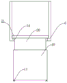
图4为本发明提供的裂缝检测显示组件、滑动放置架和L字形挡板的主视图;Fig. 4 is the front view of the crack detection display assembly, the sliding shelf and the L-shaped baffle provided by the present invention;
图5为本发明提供的裂缝检测显示组件的剖面图;Fig. 5 is a cross-sectional view of the crack detection display assembly provided by the present invention;
图6为本发明提供的喷射瓣膜一的俯视图;Fig. 6 is a top view of jet valve 1 provided by the present invention;
图7为图5的A部分的局部放大图。FIG. 7 is a partially enlarged view of part A of FIG. 5 .
其中,1、裂缝检测显示组件,2、环绕钻进组件,3、升降组件,4、设备底座,5、滑动放置架,6、L字形挡板,7、流体容纳槽,8、磁流体,9、流体流动槽一,10、柔性外壳部分,11、喷射瓣膜一,12、倾斜导流管一,13、底部支脚一,14、流体流动槽二,15、喷射瓣膜二,16、倾斜导流管二,17、底部支脚二,18、内部磁铁容纳腔,19、小磁铁,20、顶部连接台,21、吸盘式电磁铁,22、钻进电机,23、钻进保留腔,24、环绕钻进台,25、钻进刀头,26、钻进连接台,27、升降电机,28、电机支架,29、滚珠丝杠,30、丝杠螺母,31、升降连接台,32、升降导向杆,33、贯穿移动口。Among them, 1. Crack detection display component, 2. Surrounding drilling component, 3. Lifting component, 4. Equipment base, 5. Sliding shelf, 6. L-shaped baffle, 7. Fluid holding tank, 8. Magnetic fluid, 9. Fluid flow tank one, 10. Flexible shell part, 11. Jet valve one, 12. Inclined guide tube one, 13. Bottom leg one, 14. Fluid flow tank two, 15. Jet valve two, 16. Inclined guide tube Flow tube two, 17, bottom leg two, 18, internal magnet accommodation cavity, 19, small magnet, 20, top connection platform, 21, sucker type electromagnet, 22, drilling motor, 23, drilling retention cavity, 24, Surrounding drilling platform, 25, drilling head, 26, drilling connection platform, 27, lifting motor, 28, motor support, 29, ball screw, 30, screw nut, 31, lifting connection platform, 32, lifting Guide rod, 33, runs through the moving port.
附图用来提供对本发明的进一步理解,并且构成说明书的一部分,与本发明的实施例一起用于解释本发明,并不构成对本发明的限制。The accompanying drawings are used to provide a further understanding of the present invention, and constitute a part of the description, and are used together with the embodiments of the present invention to explain the present invention, and do not constitute a limitation to the present invention.
具体实施方式Detailed ways
下面将结合本发明实施例中的附图,对本发明实施例中的技术方案进行清楚、完整地描述,显然,所描述的实施例仅仅是本发明一部分实施例,而不是全部的实施例;基于本发明中的实施例,本领域普通技术人员在没有做出创造性劳动前提下所获得的所有其他实施例,都属于本发明保护的范围。The technical solutions in the embodiments of the present invention will be clearly and completely described below in conjunction with the accompanying drawings in the embodiments of the present invention. Obviously, the described embodiments are only some of the embodiments of the present invention, not all of them; based on The embodiments of the present invention and all other embodiments obtained by persons of ordinary skill in the art without making creative efforts belong to the protection scope of the present invention.
在本发明的描述中,需要理解的是,术语“上”、“下”、“前”、“后”、“左”、“右”、“顶”、“底”、“内”、“外”等指示方位或位置关系为基于附图所示的方位或位置关系,仅是为了便于描述本发明和简化描述,而不是指示或暗示所指的装置或元件必须具有特定的方位、以特定的方位构造和操作,因此不能理解为对本发明的限制。In describing the present invention, it should be understood that the terms "upper", "lower", "front", "rear", "left", "right", "top", "bottom", "inner", " "Outside" and other indication orientations or positional relationships are based on the orientations or positional relationships shown in the drawings, and are only for the convenience of describing the present invention and simplifying the description, rather than indicating or implying that the referred device or element must have a specific orientation, with a specific configuration and operation, and therefore should not be construed as limiting the invention.
如图1所示,本发明提供了一种沥青路面裂缝检测设备及其使用方法,包括裂缝检测显示组件1、环绕钻进组件2、升降组件3、设备底座4、滑动放置架5和L字形挡板6,升降组件3设于设备底座4上,环绕钻进组件2设于升降组件3上,滑动放置架5设于升降组件3上,L字形挡板6分两组固接于滑动放置架5上,裂缝检测显示组件1移动设于L字形挡板6上。As shown in Figure 1, the present invention provides an asphalt pavement crack detection device and its use method, including a crack detection display component 1, a surrounding
如图4-图7所示,裂缝检测显示组件1包括流体容纳槽7、磁流体8、流体流动槽一9、柔性外壳部分10、喷射瓣膜一11、倾斜导流管一12、底部支脚一13、流体流动槽二14、喷射瓣膜二15、倾斜导流管二16、底部支脚二17、内部磁铁容纳腔18、小磁铁19、顶部连接台20和吸盘式电磁铁21,吸盘式电磁铁21架设于两组L字形挡板6的底部之间,顶部连接台20固接于吸盘式电磁铁21的底部,柔性外壳部分10固接于顶部连接台20的底部,流体容纳槽7设于柔性外壳部分10内,流体流动槽一9设于柔性外壳部分10内的一侧,流体流动槽二14设于柔性外壳部分10内的另一侧,磁流体8填充设于流体容纳槽7、流体流动槽一9和流体流动槽二14内,喷射瓣膜一11连通设于流体流动槽一9的底部,喷射瓣膜二15连通设于流体流动槽二14的底部,倾斜导流管一12连通设于喷射瓣膜一11的底部,倾斜导流管二16连通设于喷射瓣膜二15的底部,底部支脚一13固接于柔性外壳部分10的底部的一侧,底部支脚二17固接于柔性外壳部分10的底部的另一侧,内部磁铁容纳腔18设于柔性外壳部分10中,使得柔性外壳部分10的底部开口,小磁铁19阵列设于内部磁铁容纳腔18的壁上。As shown in Figures 4-7, the crack detection and display assembly 1 includes a
如图1-图3所示,环绕钻进组件2包括钻进电机22、钻进保留腔23、环绕钻进台24、钻进刀头25和钻进连接台26,钻进电机22的机身设于升降组件3上,钻进连接台26固接于钻进电机22的输出端上,环绕钻进台24环绕固接于钻进连接台26的底部,钻进刀头25设于环绕钻进台24的底部,钻进保留腔23设于钻进连接台26内。As shown in Figures 1-3, the surrounding
如图1所示,升降组件3包括升降电机27、电机支架28、滚珠丝杠29、丝杠螺母30、升降连接台31和升降导向杆32,升降导向杆32固接于设备底座4上,滚珠丝杠29转动设于设备底座4上,丝杠螺母30传动设于滚珠丝杠29上,升降连接台31设于丝杠螺母30上并贯穿滑动于升降导向杆32上,电机支架28固接于设备底座4上,升降电机27的机身设于电机支架28上,升降电机27的输出端连接于滚珠丝杠29的顶部,滑动放置架5固接于升降连接台31的外壁上,两组L字形挡板6之间形成了贯穿移动口33,柔性外壳部分10和顶部连接台20均能够移动穿过贯穿移动口33。As shown in Figure 1, the lifting assembly 3 includes a lifting
如图5和图7所示,内部磁铁容纳腔18呈圆柱形,流体容纳槽7和流体流动槽一9与流体流动槽二14相连通,倾斜导流管一12和倾斜导流管二16向内侧弯折设置。As shown in Fig. 5 and Fig. 7, the inner
如图6所示,喷射瓣膜一11和喷射瓣膜二15运用了心脏瓣膜的原理,受压时打开,不受压时闭合。As shown in FIG. 6 , jetting valve 1 11 and jetting
相应的,本发明还提出了一种沥青路面裂缝检测设备的使用方法,包括如下步骤:Correspondingly, the present invention also proposes a method for using an asphalt pavement crack detection device, comprising the steps of:
步骤一:先将本设备移动至需要检测的沥青路面,使得设备底座4置于沥青路面上;Step 1: First move the device to the asphalt road surface to be tested, so that the equipment base 4 is placed on the asphalt road surface;
步骤二:启动钻进电机22,使得环绕钻进台24带动钻进刀头25高速转动,再启动升降电机27,于是滚珠丝杠29转动,使得丝杠螺母30移动,于是升降连接台31通过丝杠螺母30沿着升降导向杆32向下运动,使得钻进刀头25、钻进保留腔23钻入沥青路面,当钻进刀头25在路面上形成了环形槽以及钻进保留腔23中形成了沥青柱后,停止钻进;Step 2: start the
步骤三:通过升降组件3再将环绕钻进组件2上升至脱离路面,然后手持吸盘式电磁铁21,将裂缝检测显示组件1整体向上滑动,取出裂缝检测显示组件1后,手持裂缝检测显示组件1,使得倾斜导流管一12、倾斜导流管二16进入沥青路面上钻出的环形槽内,还需要操作人员握住柔性外壳部分10,使得柔性外壳部分10不进入沥青路面上钻出的环形槽,向下压柔性外壳部分10的顶部,使得磁流体8流入沥青路面上钻出的环形槽,使得沥青路面上钻出的环形槽被磁流体8填满,等待五分钟后,磁流体8均匀地填充在了沥青路面上钻出的环形槽以及钻进形成的沥青柱表面分布的裂缝中;Step 3: Use the lifting component 3 to lift the surrounding
步骤四:接着将裂缝检测显示组件1翻转180度,通过吸盘式电磁铁21使得磁流体8被吸附,而进入沥青柱侧壁裂缝中的磁流体8仍会在该裂缝中存有残留,此时再将裂缝检测显示组件1翻转180度,将柔性外壳部分10的下半部分和小磁铁19插入沥青路面上钻出的环形槽内,于是沥青柱侧壁裂缝中残留的磁流体8被小磁铁19吸附,向上取出裂缝检测显示组件1,使得柔性外壳部分10的下半部分和小磁铁19完全脱离沥青路面上钻出的环形槽,此时流体容纳槽7内的磁流体8已排干,而柔性外壳部分10由高弹性聚合物材料制成,于是可向上外翻柔性外壳部分10,使得内部磁铁容纳腔18和小磁铁19向上外翻并露出,此时再将裂缝检测显示组件1翻转180度,露出的若干组小磁铁19上分布了轨迹不同的磁流体8,磁流体8排布的形状即表示裂缝大体的位置、走向、长度、宽度;Step 4: Then turn the crack detection display assembly 1 over 180 degrees, and the
步骤五:根据若干次检测试验中磁流体8在小磁铁19上分布的轨迹和情况即可分析出一片沥青路面内部裂缝的具体情况。Step 5: According to the trajectory and situation of the distribution of the
具体使用时,先将本设备移动至需要检测的沥青路面,使得设备底座4置于沥青路面上,启动钻进电机22,使得环绕钻进台24带动钻进刀头25高速转动,再启动升降电机27,于是滚珠丝杠29转动,使得丝杠螺母30移动,于是升降连接台31通过丝杠螺母30沿着升降导向杆32向下运动,使得钻进刀头25、钻进保留腔23钻入沥青路面,很快,钻进刀头25在路面上形成了环形槽,而钻进保留腔23中形成了沥青柱,此时通过升降组件3再将环绕钻进组件2上升至脱离路面,然后手持吸盘式电磁铁21,将裂缝检测显示组件1整体向上滑动,直至其脱离贯穿移动口33和L字形挡板6,此时便取出裂缝检测显示组件1,手持裂缝检测显示组件1,使得倾斜导流管一12、倾斜导流管二16进入沥青路面上钻出的环形槽内,但需要操作人员握住柔性外壳部分10,使得柔性外壳部分10不进入沥青路面上钻出的环形槽,向下压柔性外壳部分10的顶部,使得流体容纳槽7内的磁流体8沿着流体流动槽一9、流体流动槽二14流动,并使得喷射瓣膜一11、喷射瓣膜二15打开,于是磁流体8通过倾斜导流管一12、倾斜导流管二16流入沥青路面上钻出的环形槽,使得沥青路面上钻出的环形槽被磁流体8填满,等待五分钟后,磁流体8填充在了沥青路面上钻出的环形槽以及钻进形成的沥青柱上的裂缝中,接着将裂缝检测显示组件1翻转180度,使得吸盘式电磁铁21位于沥青路面上钻出的环形槽的上方,启动吸盘式电磁铁21,由于磁流体8中的主要成分为四氧化三铁,于是此时磁流体8被吸盘式电磁铁21吸附,而进入沥青柱侧壁裂缝中的磁流体8仍会在该裂缝中存有残留,此时再将裂缝检测显示组件1翻转180度,将柔性外壳部分10的下半部分和小磁铁19插入沥青路面上钻出的环形槽内,到达底部后底部支脚一13和底部支脚二17作为支撑,于是沥青柱侧壁裂缝中残留的磁流体8被小磁铁19吸附,残留的磁流体8在若干组小磁铁19上排布的形状即表示裂缝大体的分布位置和情况,等待片刻后,向上取出裂缝检测显示组件1,使得柔性外壳部分10的下半部分和小磁铁19完全脱离沥青路面上钻出的环形槽,此时流体容纳槽7内的磁流体8已排干,而柔性外壳部分10由高弹性聚合物材料制成,于是可向上外翻柔性外壳部分10,使得内部磁铁容纳腔18和小磁铁19外翻并露出,此时再将裂缝检测显示组件1翻转180度,露出的若干组小磁铁19上分布了轨迹不同的磁流体8,磁流体8排布的形状即表示裂缝大体的位置、走向、长度、宽度,本发明提供了一种能够直观体现裂缝具体分布位置的方案,能够直观地反应路面内部的龟裂程度;由于钻进刀头25、钻进保留腔23的尺寸固定,且倾斜导流管一12、倾斜导流管二16位置与钻进刀头25在沥青路面上留下的槽对应,因此,磁流体8能够直接流入在沥青路面上钻出的环形槽中,而柔性外壳部分10的下半部分和小磁铁19能够整个进入沥青路面上钻出的环形槽中,便于进行后续的裂缝检测工作;本发明在检测时无需进行沥青路面取芯,而只需在路面上钻出一个较浅的环形槽即可,检测方便快捷,检测结果易懂,也便于修补,实施成本低。When in specific use, first move the device to the asphalt road surface that needs to be detected, so that the equipment base 4 is placed on the asphalt road surface, start the
需要说明的是,在本文中,诸如第一和第二等之类的关系术语仅仅用来将一个实体或者操作与另一个实体或操作区分开来,而不一定要求或者暗示这些实体或操作之间存在任何这种实际的关系或者顺序。而且,术语“包括”、“包含”或者其任何其他变体意在涵盖非排他性的包含,从而使得包括一系列要素的过程、方法、物品或者设备不仅包括那些要素,而且还包括没有明确列出的其他要素,或者是还包括为这种过程、方法、物品或者设备所固有的要素。It should be noted that in this article, relational terms such as first and second are only used to distinguish one entity or operation from another entity or operation, and do not necessarily require or imply that there is a relationship between these entities or operations. There is no such actual relationship or order between them. Furthermore, the term "comprises", "comprises" or any other variation thereof is intended to cover a non-exclusive inclusion such that a process, method, article, or apparatus comprising a set of elements includes not only those elements, but also includes elements not expressly listed. other elements of or also include elements inherent in such a process, method, article, or apparatus.
尽管已经示出和描述了本发明的实施例,对于本领域的普通技术人员而言,可以理解在不脱离本发明的原理和精神的情况下可以对这些实施例进行多种变化、修改、替换和变型,本发明的范围由所附权利要求及其等同物限定。Although the embodiments of the present invention have been shown and described, those skilled in the art can understand that various changes, modifications and substitutions can be made to these embodiments without departing from the principle and spirit of the present invention. and modifications, the scope of the invention is defined by the appended claims and their equivalents.
以上对本发明及其实施方式进行了描述,这种描述没有限制性,附图中所示的也只是本发明的实施方式之一,实际的结构并不局限于此。总而言之如果本领域的普通技术人员受其启示,在不脱离本发明创造宗旨的情况下,不经创造性的设计出与该技术方案相似的结构方式及实施例,均应属于本发明的保护范围。The present invention and its implementations have been described above, and this description is not limiting. What is shown in the drawings is only one of the implementations of the present invention, and the actual structure is not limited thereto. All in all, if a person of ordinary skill in the art is inspired by it, and without departing from the inventive concept of the present invention, without creatively designing a structure and an embodiment similar to the technical solution, it shall fall within the scope of protection of the present invention.
Claims (8)
Priority Applications (1)
| Application Number | Priority Date | Filing Date | Title |
|---|---|---|---|
| CN202310168291.4A CN115856069B (en) | 2023-02-27 | 2023-02-27 | An asphalt pavement crack detection device and its application method |
Applications Claiming Priority (1)
| Application Number | Priority Date | Filing Date | Title |
|---|---|---|---|
| CN202310168291.4A CN115856069B (en) | 2023-02-27 | 2023-02-27 | An asphalt pavement crack detection device and its application method |
Publications (2)
| Publication Number | Publication Date |
|---|---|
| CN115856069A CN115856069A (en) | 2023-03-28 |
| CN115856069B true CN115856069B (en) | 2023-05-05 |
Family
ID=85659046
Family Applications (1)
| Application Number | Title | Priority Date | Filing Date |
|---|---|---|---|
| CN202310168291.4A Expired - Fee Related CN115856069B (en) | 2023-02-27 | 2023-02-27 | An asphalt pavement crack detection device and its application method |
Country Status (1)
| Country | Link |
|---|---|
| CN (1) | CN115856069B (en) |
Families Citing this family (3)
| Publication number | Priority date | Publication date | Assignee | Title |
|---|---|---|---|---|
| CN117469476B (en) * | 2023-12-28 | 2024-04-02 | 临汾淼森能源工程有限公司 | Fixing support for heating pipeline |
| CN117664557B (en) * | 2024-01-29 | 2024-04-09 | 安徽省特种设备检测院 | Elevator test device |
| CN118150316B (en) * | 2024-05-09 | 2024-08-30 | 沛县万豪纺织科技有限公司 | Toughness detection equipment for cotton yarn |
Citations (5)
| Publication number | Priority date | Publication date | Assignee | Title |
|---|---|---|---|---|
| CN102012221A (en) * | 2010-10-27 | 2011-04-13 | 中公高科(北京)养护科技有限公司 | Ground penetrating radar-based pavement crack depth nondestructive test method |
| CN110178045A (en) * | 2016-11-17 | 2019-08-27 | 特里纳米克斯股份有限公司 | Detector at least one object of optical detection |
| CN111364338A (en) * | 2020-03-24 | 2020-07-03 | 长安大学 | Highway asphalt pavement crack repairing device and method |
| CN111691281A (en) * | 2020-06-19 | 2020-09-22 | 滨州学院 | Device for breaking concrete layer on pavement by subsonic particle flow impact and construction method |
| CN112964862A (en) * | 2021-02-05 | 2021-06-15 | 泗洪县城市建设投资经营集团有限公司 | High-elastic rubber asphalt composite broken stone seal on-site detection device |
Family Cites Families (8)
| Publication number | Priority date | Publication date | Assignee | Title |
|---|---|---|---|---|
| JP2003119717A (en) * | 2001-10-18 | 2003-04-23 | Mitsui Chemicals Inc | Pavement diagnosing sheet and pavement nondestruction diagnosing method |
| CN104727207B (en) * | 2015-03-31 | 2016-08-17 | 东南大学 | A kind of semi-rigid base asphalt pavement structure maintenance method for designing |
| CN205038019U (en) * | 2015-10-23 | 2016-02-17 | 沈阳鸿润水利工程有限公司 | Dykes and dams antiseep monitoring devices |
| KR102184399B1 (en) * | 2020-04-20 | 2020-11-30 | 서윤석 | Repairing method for sunken pavement |
| CN212748756U (en) * | 2020-07-29 | 2021-03-19 | 北京路桥通国际工程咨询有限公司 | Pavement crack detector |
| CN214224979U (en) * | 2021-01-20 | 2021-09-17 | 杨树春 | Bridge bituminous pavement crack detection device |
| CN214909449U (en) * | 2021-04-23 | 2021-11-30 | 宁夏医科大学总医院 | Novel hospital bed for nursing heart failure patients |
| CN218175525U (en) * | 2022-08-28 | 2022-12-30 | 戴叶华 | Road and bridge bituminous pavement crack detection device |
-
2023
- 2023-02-27 CN CN202310168291.4A patent/CN115856069B/en not_active Expired - Fee Related
Patent Citations (5)
| Publication number | Priority date | Publication date | Assignee | Title |
|---|---|---|---|---|
| CN102012221A (en) * | 2010-10-27 | 2011-04-13 | 中公高科(北京)养护科技有限公司 | Ground penetrating radar-based pavement crack depth nondestructive test method |
| CN110178045A (en) * | 2016-11-17 | 2019-08-27 | 特里纳米克斯股份有限公司 | Detector at least one object of optical detection |
| CN111364338A (en) * | 2020-03-24 | 2020-07-03 | 长安大学 | Highway asphalt pavement crack repairing device and method |
| CN111691281A (en) * | 2020-06-19 | 2020-09-22 | 滨州学院 | Device for breaking concrete layer on pavement by subsonic particle flow impact and construction method |
| CN112964862A (en) * | 2021-02-05 | 2021-06-15 | 泗洪县城市建设投资经营集团有限公司 | High-elastic rubber asphalt composite broken stone seal on-site detection device |
Also Published As
| Publication number | Publication date |
|---|---|
| CN115856069A (en) | 2023-03-28 |
Similar Documents
| Publication | Publication Date | Title |
|---|---|---|
| CN115856069B (en) | An asphalt pavement crack detection device and its application method | |
| CN115597792B (en) | Syringe performance detection device | |
| CN103000857B (en) | Liquid injection device and liquid injection method for battery electrolyte | |
| CN103786907A (en) | Vacuum tank capable of simulating vacuum environment of moon and provided with rotatable inner cylinder | |
| CN112033744A (en) | Water stratification precision sampling device | |
| CN109406062B (en) | Elbow sealing test device | |
| CN110243750B (en) | Sampler and flow cytometer using same | |
| CN203405311U (en) | Casting sealing performance detection device | |
| CN107014716A (en) | A kind of Cigarette Draw Resistance detection means | |
| CN111811444B (en) | Finished product detection mechanism of lens shearing machine | |
| CN115343110B (en) | Laboratory intelligent sample sampling robot | |
| CN219142348U (en) | Liquid sample sampling device of medical examination equipment | |
| CN112362339B (en) | Life testing device for low-temperature valve with air filling port | |
| CN105784962A (en) | Pumping-type water-gas absorption coal body deformation test device and pumping-type water-gas absorption coal body deformation test method | |
| CN207662578U (en) | A kind of vacuum cup sealing propertytest testing stand | |
| CN218916685U (en) | Performance detection device of sealing ring | |
| CN114778016B (en) | Air tightness detection device for canned food cans | |
| CN105758676B (en) | Mixer-settler samplers at different levels in a kind of hot cell | |
| CN115847480A (en) | Angle-adjustable functional head and intelligent platform system | |
| CN220737638U (en) | Chemical reagent supply device | |
| CN219416342U (en) | A volume detection equipment for soy sauce bottle production | |
| CN221610730U (en) | Vacuum structure and equipment for testing high vacuum door valve | |
| CN207689180U (en) | A kind of sampler of graininess detection of agricultural products | |
| CN207689201U (en) | Sampling container | |
| CN207662689U (en) | Rock sample perfusion device |
Legal Events
| Date | Code | Title | Description |
|---|---|---|---|
| PB01 | Publication | ||
| PB01 | Publication | ||
| SE01 | Entry into force of request for substantive examination | ||
| SE01 | Entry into force of request for substantive examination | ||
| GR01 | Patent grant | ||
| GR01 | Patent grant | ||
| CF01 | Termination of patent right due to non-payment of annual fee | ||
| CF01 | Termination of patent right due to non-payment of annual fee |
Granted publication date: 20230505 |