CN115822536B - Carbon dioxide injection replacement type coalbed methane acquisition device and application method thereof - Google Patents
Carbon dioxide injection replacement type coalbed methane acquisition device and application method thereof Download PDFInfo
- Publication number
- CN115822536B CN115822536B CN202310081557.1A CN202310081557A CN115822536B CN 115822536 B CN115822536 B CN 115822536B CN 202310081557 A CN202310081557 A CN 202310081557A CN 115822536 B CN115822536 B CN 115822536B
- Authority
- CN
- China
- Prior art keywords
- air
- carbon dioxide
- gas
- cylinder
- connecting rod
- Prior art date
- Legal status (The legal status is an assumption and is not a legal conclusion. Google has not performed a legal analysis and makes no representation as to the accuracy of the status listed.)
- Expired - Fee Related
Links
Images


Landscapes
- Filling Or Discharging Of Gas Storage Vessels (AREA)
- Devices For Medical Bathing And Washing (AREA)
Abstract
本发明涉及煤层气采集技术领域,具体涉及一种二氧化碳注入置换式煤层气采集装置,包括注气筒、抽气筒、连接管和隔板,注气筒和抽气筒上均设有若干个第一通孔,注气筒的连接管上设有出气口,抽气筒的连接管上设有抽气口,隔板的上下侧均设有压气组件,注气筒位于煤层处设有封闭筒,封闭筒上设有若干个第二通孔,注气筒的隔板上设有驱动件,通过驱动件带动封闭筒转动,通过封闭筒带动第二通孔转动,完成与第一通孔的连通与封闭,从而进行二氧化碳的置换工作和封闭煤层气进入注气筒内的工作,解决了现有二氧化碳置换过程中,注入的二氧化碳与煤层气中的二氧化碳混合,导致二氧化碳检测含量过高,提前结束煤层气开采,降低了煤层气开采效率的问题。
The invention relates to the technical field of coalbed methane collection, in particular to a carbon dioxide injection replacement type coalbed methane collection device, which includes an air injection cylinder, an air extraction cylinder, a connecting pipe and a partition, and several first through holes are arranged on the gas injection cylinder and the air extraction cylinder , the connecting pipe of the air injection cylinder is provided with an air outlet, the connecting pipe of the air extraction cylinder is provided with an air outlet, the upper and lower sides of the partition are equipped with compressed air components, and the air injection cylinder is located at the coal seam. A closed cylinder is installed on the closed cylinder. There is a second through hole, a driving part is provided on the partition plate of the gas injection cylinder, the driving part drives the closed cylinder to rotate, and the closed cylinder drives the second through hole to rotate to complete the communication and sealing with the first through hole, so as to carry out the carbon dioxide inhalation. The replacement work and the work of sealing the coalbed methane into the gas injection cylinder solve the problem that during the existing carbon dioxide replacement process, the injected carbon dioxide mixes with the carbon dioxide in the coalbed methane, which leads to an excessively high detected content of carbon dioxide, ends the mining of coalbed methane ahead of time, and reduces the cost of coalbed methane. The problem of extraction efficiency.
Description
技术领域technical field
本发明涉及煤层气采集技术领域,尤其涉及一种二氧化碳注入置换式煤层气采集装置及其使用方法。The invention relates to the technical field of coalbed methane collection, in particular to a carbon dioxide injection displacement type coalbed methane collection device and a use method thereof.
背景技术Background technique
在煤层气开采工作中,由于二氧化碳的竞争吸附强度远远大于氮气,因此,二氧化碳作为置换或驱替煤层中的甲烷,已成为新的煤层气强化开发方式,在公开号为CN110425003B,提出了一件发明专利为一种提高煤层气开发直井、定向井井组中煤层气采收率的开采方法,通过煤层气直井、定向井井组开发背景,利用二氧化碳对甲烷的置换、驱替作用实现煤层气的高效开采,可显著提高煤层气资源采收率。In the mining of coalbed methane, since the competitive adsorption intensity of carbon dioxide is far greater than that of nitrogen, carbon dioxide, as a replacement or displacement of methane in coal seams, has become a new method of intensified development of coalbed methane. In the publication number CN110425003B, a proposal was made The invention patent is a mining method for improving the recovery rate of coalbed methane in vertical wells and directional wells for coalbed methane development. Through the development background of vertical wells and directional wells for coalbed methane, the replacement and displacement of methane by carbon dioxide is used to realize coalbed methane recovery. The efficient exploitation of natural gas can significantly improve the recovery rate of coalbed methane resources.
但是在上述专利方案中,存在一定的问题,直接将二氧化碳注入井中,存在部分二氧化碳未进行置换,导致采集的煤层气中,二氧化碳偏高,关井后,注入的二氧化碳完成置换,导致部分煤层气不能充分采集,降低了煤层气开采效率,因此,急需一种高效置换煤层气进行开采的装置。However, in the above-mentioned patent scheme, there are certain problems. When carbon dioxide is directly injected into the well, part of the carbon dioxide has not been replaced, resulting in high carbon dioxide in the collected coalbed methane. The insufficient collection reduces the efficiency of coalbed methane mining. Therefore, there is an urgent need for a device for efficient replacement of coalbed methane for mining.
发明内容Contents of the invention
有鉴于此,本发明的目的在于提出一种二氧化碳注入置换式煤层气采集装置及其使用方法,以解决现有二氧化碳置换过程中,注入的二氧化碳与煤层气中的二氧化碳混合,导致二氧化碳检测含量过高,提前结束煤层气开采,降低了煤层气开采效率的问题。In view of this, the purpose of the present invention is to propose a carbon dioxide injection displacement coalbed methane collection device and its use method to solve the problem that the injected carbon dioxide is mixed with the carbon dioxide in the coalbed methane during the existing carbon dioxide replacement process, resulting in excessive detection of carbon dioxide. High, ending coalbed methane mining ahead of schedule reduces the efficiency of coalbed methane mining.
基于上述目的,本发明提供了一种二氧化碳注入置换式煤层气采集装置,包括若干个置换采气机构,每个置换采气机构均包括注气筒和抽气筒,所述注气筒和抽气筒的外壁上均设有若干个与煤层连通的第一通孔,所述注气筒和抽气筒的内部均设有连接管,所述注气筒的连接管上设有出气口,所述抽气筒的连接管上设有抽气口,所述连接管上均套设有用于分隔上下煤层的隔板,每个所述隔板的上下侧均设有压气组件,所述注气筒位于煤层处均设有可在注气筒内部旋转的封闭筒,每个所述封闭筒上均设有若干个与所有第一通孔一一对应的第二通孔,且所述注气筒的隔板上设有通过调节可单独带动一个封闭筒转动的驱动件;Based on the above purpose, the present invention provides a carbon dioxide injection displacement coalbed methane collection device, which includes several displacement gas recovery mechanisms, each displacement gas recovery mechanism includes a gas injection cylinder and an air extraction cylinder, and the outer walls of the gas injection cylinder and the air extraction cylinder There are a number of first through holes communicating with the coal seam, the inside of the gas injection cylinder and the air extraction cylinder are equipped with connecting pipes, the connection pipe of the gas injection cylinder is provided with an air outlet, and the connection pipe of the air extraction cylinder There is an air extraction port on the top, and the connecting pipe is set with partitions for separating the upper and lower coal seams. The upper and lower sides of each partition are equipped with compressed air components, and the gas injection cylinders are located at the coal seam. The closed cylinder that rotates inside the gas injection cylinder, each of the closed cylinders is provided with a number of second through holes corresponding to all the first through holes, and the partition plate of the gas injection cylinder is equipped with A driving member that drives a closed cylinder to rotate;
其中,注气筒和抽气筒内压气组件的工作状态相反,当注气筒内的压气组件压气时,抽气筒内的压气组件进行吸气工作,以使二氧化碳气体快速进入煤层将煤层气置换到抽气筒中。Among them, the working state of the compressed air components in the gas injection cylinder and the air extraction cylinder is opposite. When the compressed air components in the air injection cylinder are compressed, the compressed air components in the air extraction cylinder perform suction work, so that carbon dioxide gas can quickly enter the coal seam and replace the coalbed methane into the air extraction cylinder. middle.
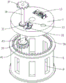
优选的,所述出气口上设有涡轮箱,所述涡轮箱的内部铰设有涡轮扇叶,所述涡轮箱的外侧架设有发电机,所述发电机与所述涡轮扇叶转动连接,所述注气筒的隔板上装设有蓄电池,且所述蓄电池与所述发电机、所述压气组件和所述驱动件电性连接。Preferably, the air outlet is provided with a turbine box, the interior of the turbine box is hinged with turbine blades, the outside of the turbine box is mounted with a generator, and the generator is rotatably connected to the turbine blades, A storage battery is installed on the separator of the air injection cylinder, and the storage battery is electrically connected with the generator, the compressed air assembly and the driving member.
优选的,所述抽气口远离所述抽气筒的一端设有安装环,所述安装环的一侧与所述抽气口转动连接,另一侧向环外延伸设有四个均匀分布的聚气框,每个所述聚气框均与所述安装环固定连接,每个所述聚气框的进气端分别靠近另一个所述聚气框设置,每个所述聚气框的出气端均靠近所述安装环的中心处设置,所述安装环的内部设有十字架,所述十字架的中心处设有连接轴,所述连接轴上设有第一锥齿轮,所述抽气口上架设有第一电机,所述第一电机的输出轴穿设在所述抽气口的内部,所述抽气口的内部设有第二锥齿轮,所述第二锥齿轮与所述第一电机的输出轴转动连接,且所述第二锥齿轮与所述第一锥齿轮啮合。Preferably, an installation ring is provided at the end of the air extraction port away from the air extraction tube, one side of the installation ring is rotatably connected to the air extraction port, and four evenly distributed gas gathering rings are provided on the other side extending outward from the ring. frame, each of the gas gathering frames is fixedly connected to the installation ring, the inlet end of each of the gas gathering frames is set close to the other gas gathering frame, and the gas outlet of each of the gas gathering frames They are all arranged close to the center of the installation ring, a cross is arranged inside the installation ring, a connecting shaft is arranged at the center of the cross, a first bevel gear is arranged on the connecting shaft, and a There is a first motor, the output shaft of the first motor is passed through the inside of the air suction port, the inside of the air suction port is provided with a second bevel gear, and the output shaft of the second bevel gear and the first motor The shaft is rotationally connected, and the second bevel gear meshes with the first bevel gear.
优选的,所述抽气口远离所述抽气筒的一侧设有环形凹槽,所述安装环靠近所述抽气口的一侧设有环形凸块,且所述环形凹槽套设在所述环形凸块上。Preferably, an annular groove is provided on the side of the air extraction port away from the air extraction cylinder, an annular protrusion is provided on the side of the installation ring close to the air extraction port, and the annular groove is sleeved on the on the ring bump.
优选的,所述聚气框的内部设有倾斜设置的斜板。Preferably, the inside of the air collecting frame is provided with inclined plates arranged obliquely.
优选的,所述压气组件包括:Preferably, the compressed air assembly includes:
第一连接杆,穿设在所述隔板上,且所述第一连接杆上设有用于所述隔板上下层通气的条形缺口;The first connecting rod is passed through the partition, and the first connecting rod is provided with a strip-shaped gap for the ventilation of the upper and lower layers of the partition;
往复组件,设置在所述隔板上,所述往复组件与所述第一连接杆传动连接,且所述往复组件用于带动所述第一连接杆上下移动;A reciprocating assembly is arranged on the separator, the reciprocating assembly is in transmission connection with the first connecting rod, and the reciprocating assembly is used to drive the first connecting rod to move up and down;
两个活塞,均套设在所述连接管上,且每个所述活塞的一侧分别与所述第一连接杆的一端固定连接。Two pistons are sleeved on the connecting pipe, and one side of each piston is fixedly connected to one end of the first connecting rod.
优选的,所述往复组件包括:Preferably, the reciprocating assembly includes:
安装板,竖直地设置在所述隔板上;the mounting plate is vertically arranged on the partition;
飞镖插板,设置在所述安装板远离所述第一连接杆的一侧,所述飞镖插板的四周设有若干个均匀分布的限位杆,所述飞镖插板的每个插头均通过转动穿设在两个限位杆中间,且每个所述限位杆均与所述安装板固定连接;The dart board is arranged on the side of the mounting plate away from the first connecting rod, and several evenly distributed limit rods are arranged around the dart board, and each plug of the dart board passes through The rotation passes through the middle of the two limit rods, and each of the limit rods is fixedly connected with the installation plate;
连接臂,其一端与所述第一连接杆铰接,且另一端与所述飞镖插板的一个插头铰接;A connecting arm, one end of which is hinged to the first connecting rod, and the other end is hinged to a plug of the dart board;
第二电机,架设在所述隔板上;The second motor is erected on the partition;
圆盘,设置在所述飞镖插板远离连接臂的一侧,所述圆盘的中心处与所述第二电机的输出轴转动连接,且所述圆盘靠近外圆的一处与所述飞镖插板的中心处铰接。The disk is arranged on the side of the dart board away from the connecting arm, the center of the disk is connected to the output shaft of the second motor in rotation, and a part of the disk near the outer circle is connected to the The center of the dartboard is hinged.
优选的,所述驱动件包括:Preferably, the driver includes:
第三电机,架设在所述隔板上;The third motor is erected on the partition;
第一齿轮,与所述第三电机的输出轴转动连接;The first gear is rotatably connected to the output shaft of the third motor;
第二连接杆,穿设在所述隔板上;The second connecting rod is arranged on the partition;
第二齿轮,套设在所述第二连接杆上,且所述第二齿轮与所述第一齿轮啮合;a second gear, sleeved on the second connecting rod, and the second gear meshes with the first gear;
轴套,套设在所述第二连接杆的一端,且所述轴套与所述第二连接杆之间转动连接;A shaft sleeve is sleeved on one end of the second connecting rod, and the shaft sleeve is rotatably connected to the second connecting rod;
电动推杆,设置在所述隔板上,且所述电动推杆的伸缩杆与所述轴套传动连接;The electric push rod is arranged on the partition, and the telescopic rod of the electric push rod is connected to the shaft sleeve through transmission;
两个环形齿条,分别设置在所述封闭筒靠近所述隔板的一侧;Two ring-shaped racks are respectively arranged on the side of the closed cylinder close to the partition;
两个第三齿轮,分别套设在所述第二连接杆的一端,且每个所述第三齿轮分别与所述环形齿条啮合。Two third gears are sheathed on one end of the second connecting rod respectively, and each of the third gears meshes with the ring rack respectively.
优选的,所述轴套的内部设有至少一个限位凸块,所述第二连接杆上设有与所有所述限位凸块一一对应的限位凹槽,每个所述限位凹槽分别套设在所述限位凸块上,所述轴套上设有限位盘,所述限位盘上设有环形滑道,所述电动推杆的伸缩杆上设有滑块,且所述滑块设置在所述环形滑道中。Preferably, at least one limit protrusion is provided inside the sleeve, and limit grooves corresponding to all the limit protrusions are provided on the second connecting rod, and each limit The grooves are respectively sleeved on the limit bumps, the bushing is provided with a limit plate, the limit plate is provided with an annular slideway, and the telescopic rod of the electric push rod is provided with a slider. And the slider is arranged in the annular slideway.
一种二氧化碳注入置换式煤层气采集装置的使用方法,包括如下步骤:A method for using a carbon dioxide injection displacement coalbed methane collection device, comprising the following steps:
S1:对注气筒中的连接管注入二氧化碳,使二氧化碳经过连接管从出气口进入注气筒中;S1: Inject carbon dioxide into the connecting tube in the gas injection cylinder, so that the carbon dioxide enters the gas injection cylinder from the gas outlet through the connecting tube;
S2:通过控制驱动件带动封闭筒转动,通过封闭筒带动第二通孔转动与第一通孔连通;S2: Drive the closed cylinder to rotate by controlling the driving part, and drive the second through hole to rotate through the closed cylinder to communicate with the first through hole;
S3:通过注气筒中的压气组件进行压气工作,将二氧化碳挤压经过第二通孔和第一通孔进入煤层中进行置换煤层气,通过抽气筒中的压气组件进行吸气工作,使煤层气快速进入抽气筒中,通过抽气口将煤层气吸入连接管内,通过地面的集气装置将连接管内的煤层气吸收,实现了二氧化碳快速置换煤层气采集工作;S3: Compress the gas through the gas compression component in the gas injection cylinder, extrude carbon dioxide into the coal seam through the second through hole and the first through hole to replace the coalbed methane, and perform the suction work through the gas compression component in the gas extraction tube to make the coal bed methane Quickly enter the air pump, suck the coalbed methane into the connecting pipe through the air suction port, and absorb the coalbed methane in the connecting pipe through the gas collection device on the ground, realizing the rapid replacement of carbon dioxide for coalbed methane collection;
S4:当二氧化碳用完时,为了避免煤层气进入注气筒,导致部分煤层气无法收集,通过控制驱动件带动封闭筒转动,通过封闭筒带动第二通孔转动,使第一通孔封闭,从而使煤层中的煤层气无法进入注气筒中。S4: When the carbon dioxide is used up, in order to prevent the coalbed methane from entering the gas injection cylinder, causing part of the coalbed gas to be unable to be collected, the closed cylinder is driven to rotate by controlling the driving part, and the second through hole is driven to rotate through the closed cylinder to close the first through hole, thereby The coalbed gas in the coal seam cannot enter the gas injection cylinder.
本发明的有益效果:通过对注气筒的连接管内注入二氧化碳,并经过出气口进入注气筒中,通过驱动件带动封闭筒转动,通过封闭筒带动第二通孔转动,通过第二通孔与第一通孔连通,通过注气筒的压气组件进行压气工作,抽气筒的压气组件进行吸气工作,从而使二氧化碳快速将煤层中的煤层气置换到抽气筒中,通过抽气口将煤层气吸入连接管取出到地面进行收集,通过驱动件带动封闭筒转动将第一通孔封闭,从而使二氧化碳停止注入时,煤层气不会从第一通孔进入注气筒中无法收集,解决了现有二氧化碳置换过程中,注入的二氧化碳与煤层气中的二氧化碳混合,导致二氧化碳检测含量过高,提前结束煤层气开采,降低了煤层气开采效率的问题。Beneficial effects of the present invention: inject carbon dioxide into the connecting pipe of the gas injection cylinder, enter the gas injection cylinder through the gas outlet, drive the closed cylinder to rotate through the driving part, drive the second through hole to rotate through the closed cylinder, and connect the second through hole with the second through hole to rotate. A through hole is connected, and the air compression component of the gas injection cylinder is used for compression work, and the gas compression component of the suction cylinder is used for suction work, so that carbon dioxide can quickly replace the coalbed methane in the coal seam into the suction cylinder, and the coalbed gas is sucked into the connecting pipe through the suction port Take it out to the ground for collection, drive the sealing cylinder to rotate through the driving part to close the first through hole, so that when the carbon dioxide injection stops, the coalbed gas will not enter the gas injection cylinder from the first through hole and cannot be collected, which solves the existing carbon dioxide replacement process In the process, the injected carbon dioxide mixes with the carbon dioxide in the coalbed methane, which leads to the detection of too high carbon dioxide content, which ends the mining of coalbed methane in advance and reduces the efficiency of coalbed methane mining.
附图说明Description of drawings
为了更清楚地说明本发明或现有技术中的技术方案,下面将对实施例或现有技术描述中所需要使用的附图作简单地介绍,显而易见地,下面描述中的附图仅仅是本发明,对于本领域普通技术人员来讲,在不付出创造性劳动的前提下,还可以根据这些附图获得其他的附图。In order to more clearly illustrate the present invention or the technical solutions in the prior art, the accompanying drawings that need to be used in the description of the embodiments or the prior art will be briefly introduced below. Obviously, the accompanying drawings in the following description are only the present invention. Invention, for those of ordinary skill in the art, other drawings can also be obtained based on these drawings without creative work.
图1为本发明实施例整体的平面结构示意图;FIG. 1 is a schematic plan view of the overall structure of an embodiment of the present invention;
图2为本发明实施例出气口处的立体结构示意图;Fig. 2 is a schematic diagram of the three-dimensional structure at the air outlet of the embodiment of the present invention;
图3为本发明实施例压气组件的立体结构示意图;Fig. 3 is a three-dimensional structural schematic diagram of a pneumatic assembly according to an embodiment of the present invention;
图4为本发明实施例图3在A处放大结构示意图;Fig. 4 is a schematic diagram of the enlarged structure at A in Fig. 3 according to an embodiment of the present invention;
图5为本发明实施例抽气口处的立体结构示意图;Fig. 5 is a schematic diagram of the three-dimensional structure at the air inlet of the embodiment of the present invention;
图6为本发明实施例图3在B处放大结构示意图;Fig. 6 is a schematic diagram of the enlarged structure at B in Fig. 3 according to an embodiment of the present invention;
图7为本发明实施例驱动件的立体结构示意图;7 is a schematic diagram of a three-dimensional structure of a driving member according to an embodiment of the present invention;
图8为本发明实施例第二连接杆与轴套之间连接的立体结构示意图。Fig. 8 is a schematic perspective view of the connection between the second connecting rod and the shaft sleeve according to the embodiment of the present invention.
图中标记为:Labeled in the figure:
1、注气筒;2、抽气筒;3、第一通孔;4、连接管;5、出气口;6、抽气口;7、隔板;8、封闭筒;9、第二通孔;10、涡轮箱;11、涡轮扇叶;12、发电机;13、蓄电池;14、安装环;15、聚气框;16、十字架;17、连接轴;18、第一锥齿轮;19、第一电机;20、第二锥齿轮;21、环形凹槽;22、环形凸块;23、斜板;24、第一连接杆;25、活塞;26、安装板;27、飞镖插板;28、限位杆;29、连接臂;30、第二电机;31、圆盘;32、第三电机;33、第一齿轮;34、第二连接杆;35、第二齿轮;36、环形齿条;37、第三齿轮;38、轴套;39、限位凸块;40、限位凹槽;41、限位盘;42、环形滑道;43、电动推杆;44、滑块;45、条形缺口。1. Air injection cylinder; 2. Air extraction cylinder; 3. First through hole; 4. Connecting pipe; 5. Air outlet; 6. Air extraction port; 7. Partition; 8. Closed cylinder; , turbine box; 11, turbine blade; 12, generator; 13, storage battery; 14, mounting ring; 15, gas collecting frame; 16, cross; 17, connecting shaft; 18, first bevel gear; 19, first Motor; 20, second bevel gear; 21, annular groove; 22, annular projection; 23, inclined plate; 24, first connecting rod; 25, piston; 26, mounting plate; 27, dart board; 28, Limit rod; 29, connecting arm; 30, second motor; 31, disc; 32, third motor; 33, first gear; 34, second connecting rod; 35, second gear; 36, ring rack ; 37, the third gear; 38, axle sleeve; 39, limit projection; 40, limit groove; 41, limit plate; 42, annular slideway; 43, electric push rod; 44, slide block; 45 , Strip notch.
具体实施方式Detailed ways
为使本发明的目的、技术方案和优点更加清楚明白,以下结合具体实施例,对本发明进一步详细说明。In order to make the object, technical solution and advantages of the present invention clearer, the present invention will be further described in detail below in conjunction with specific examples.
需要说明的是,除非另外定义,本发明使用的技术术语或者科学术语应当为本发明所属领域内具有一般技能的人士所理解的通常意义。本发明中使用的“第一”、“第二”以及类似的词语并不表示任何顺序、数量或者重要性,而只是用来区分不同的组成部分。“包括”或者“包含”等类似的词语意指出现该词前面的元件或者物件涵盖出现在该词后面列举的元件或者物件及其等同,而不排除其他元件或者物件。“连接”或者“相连”等类似的词语并非限定于物理的或者机械的连接,而是可以包括电性的连接,不管是直接的还是间接的。“上”、“下”、“左”、“右”等仅用于表示相对位置关系,当被描述对象的绝对位置改变后,则该相对位置关系也可能相应地改变。It should be noted that, unless otherwise defined, the technical terms or scientific terms used in the present invention shall have the usual meanings understood by those skilled in the art to which the present invention belongs. "First", "second" and similar words used in the present invention do not indicate any order, quantity or importance, but are only used to distinguish different components. "Comprising" or "comprising" and similar words mean that the elements or items appearing before the word include the elements or items listed after the word and their equivalents, without excluding other elements or items. Words such as "connected" or "connected" are not limited to physical or mechanical connections, but may include electrical connections, whether direct or indirect. "Up", "Down", "Left", "Right" and so on are only used to indicate the relative positional relationship. When the absolute position of the described object changes, the relative positional relationship may also change accordingly.
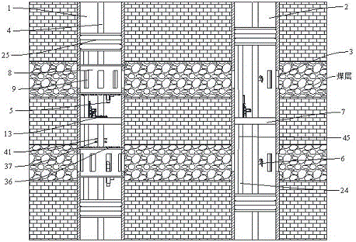
如图1至图8所示,一种二氧化碳注入置换式煤层气采集装置,包括若干个置换采气机构,每个置换采气机构均包括注气筒1和抽气筒2,所述注气筒1和抽气筒2的外壁上均设有若干个与煤层连通的第一通孔3,所述注气筒1和抽气筒2的内部均设有连接管4,所述注气筒1的连接管4上设有出气口5,所述抽气筒2的连接管4上设有抽气口6,所述连接管4上均套设有用于分隔上下煤层的隔板7,每个所述隔板7的上下侧均设有压气组件,所述注气筒1位于煤层处均设有可在注气筒1内部旋转的封闭筒8,每个所述封闭筒8上均设有若干个与所有第一通孔3一一对应的第二通孔9,且所述注气筒1的隔板7上设有通过调节可单独带动一个封闭筒8转动的驱动件;As shown in Figures 1 to 8, a carbon dioxide injection displacement coalbed methane collection device includes several displacement gas recovery mechanisms, each displacement gas recovery mechanism includes a gas injection cylinder 1 and an air extraction cylinder 2, the gas injection cylinder 1 and the gas extraction cylinder The outer wall of the air extractor 2 is provided with several first through holes 3 communicating with the coal seam, the inside of the air injection cylinder 1 and the air extractor 2 are provided with connecting
其中,注气筒1和抽气筒2内压气组件的工作状态相反,当注气筒1内的压气组件压气时,抽气筒2内的压气组件进行吸气工作,以使二氧化碳气体快速进入煤层将煤层气置换到抽气筒2中。Wherein, the working state of the compressed air component in the gas injection cylinder 1 and the air extraction cylinder 2 is opposite. When the compressed air component in the gas injection cylinder 1 is compressed, the compressed air component in the air extraction cylinder 2 performs suction work, so that the carbon dioxide gas can quickly enter the coal seam and reduce the coalbed methane. Replace it into the aspirator 2.
通过对注气筒1的连接管4内注入二氧化碳,并经过出气口5进入注气筒1中,通过驱动件带动封闭筒8转动,通过封闭筒8带动第二通孔9转动,通过第二通孔9与第一通孔3连通,通过注气筒1的压气组件进行压气工作,抽气筒2的压气组件进行吸气工作,从而使二氧化碳快速将煤层中的煤层气置换到抽气筒2中,通过抽气口6将煤层气吸入连接管4取出到地面进行收集,当注气筒1的压气组件进行吸气工作时,通过驱动件带动封闭筒8转动将第一通孔3封闭,从而使注入煤层中的二氧化碳不会出现倒灌现象,当二氧化碳停止注入时,通过驱动件带动封闭筒8转动将第一通孔3封闭,从而使煤层气不会从第一通孔3进入注气筒1中无法收集,解决了现有二氧化碳置换过程中,注入的二氧化碳与煤层气中的二氧化碳混合,导致二氧化碳检测含量过高,提前结束煤层气开采,降低了煤层气开采效率的问题。By injecting carbon dioxide into the connecting
作为一个可选实施例,所述出气口5上设有涡轮箱10,所述涡轮箱10的内部铰设有涡轮扇叶11,所述涡轮箱10的外侧架设有发电机12,所述发电机12与所述涡轮扇叶11转动连接,所述注气筒1的隔板7上装设有蓄电池13,且所述蓄电池13与所述发电机12、所述压气组件和所述驱动件电性连接。As an optional embodiment, the
举例说明,将二氧化碳注入连接管4内,需要用到增压泵,在二氧化碳从出气口5进入涡轮箱10时,通过增压泵带来的动力作用在涡轮扇叶11上,从而使二氧化碳带动涡轮扇叶11转动,通过涡轮扇叶11带动发电机12工作,将电力储存在蓄电池13上,通过蓄电池13提供电力给压气组件和驱动件,从而节约了电力,提高了资源利用率,实现了利用注入二氧化碳的流动力为注气筒1内的电气设备提供电力储备支撑的问题。For example, to inject carbon dioxide into the connecting
作为一个可选实施例,所述抽气口6远离所述抽气筒2的一端设有安装环14,所述安装环14的一侧与所述抽气口6转动连接,另一侧向环外延伸设有四个均匀分布的聚气框15,每个所述聚气框15均与所述安装环14固定连接,每个所述聚气框15的进气端分别靠近另一个所述聚气框15设置,每个所述聚气框15的出气端均靠近所述安装环14的中心处设置,所述安装环14的内部设有十字架16,所述十字架16的中心处设有连接轴17,所述连接轴17上设有第一锥齿轮18,所述抽气口6上架设有第一电机19,所述第一电机19的输出轴穿设在所述抽气口6的内部,所述抽气口6的内部设有第二锥齿轮20,所述第二锥齿轮20与所述第一电机19的输出轴转动连接,且所述第二锥齿轮20与所述第一锥齿轮18啮合。As an optional embodiment, an
举例说明,如图5所示,通过第一电机19带动第二锥齿轮20转动,通过第二锥齿轮20带动第一锥齿轮18转动,通过第一锥齿轮18带动连接轴17转动,通过连接轴17带动十字架16转动,通过十字架16带动安装环14转动,通过安装环14带动聚气框15转动,通过聚气框15将框住的煤层气经过安装环14引入抽气口6中,从而使煤层气快速从抽气口6进入连接管4内取出到地面收集,实现了提高煤层气吸收效率的问题。For example, as shown in Figure 5, the
作为一个可选实施例,所述抽气口6远离所述抽气筒2的一侧设有环形凹槽21,所述安装环14靠近所述抽气口6的一侧设有环形凸块22,且所述环形凹槽21套设在所述环形凸块22上。As an optional embodiment, an
举例说明,如图4至图5所示,通过在抽气口6上设置环形凹槽21,通过在安装环14上设置环形凸块22,通过将环形凸块22设置在环形凹槽21中,从而使安装环14在转动时,不会脱离抽气口6,实现了对安装环14在抽气口6上转动进行限位的问题。For example, as shown in FIGS. 4 to 5 , by setting the
作为一个可选实施例,所述聚气框15的内部设有倾斜设置的斜板23。As an optional embodiment, the inside of the
通过在聚气框15内设置斜板23,一方面用于减少聚气框15因转动受到煤层气的阻力,另一方面用于提高煤层气进入安装环14内的效率。By setting the
作为一个可选实施例,所述压气组件包括:As an optional embodiment, the pneumatic assembly includes:
第一连接杆24,穿设在所述隔板7上,且所述第一连接杆24上设有用于所述隔板7上下层通气的条形缺口45;The first connecting
往复组件,设置在所述隔板7上,所述往复组件与所述第一连接杆24传动连接,且所述往复组件用于带动所述第一连接杆24上下移动;The reciprocating assembly is arranged on the
两个活塞25,均套设在所述连接管4上,且每个所述活塞25的一侧分别与所述第一连接杆24的一端固定连接。Two
举例说明,如图1和图3所示,在有上下层的煤层时,为了降低能耗,通过往复组件带动第一连接杆24上下移动,通过第一连接杆24带动两个活塞25同步移动,从而使其他煤层对应的活塞25无需单独设置动力源,通过在第一连接杆24上设置条形缺口进行通气,从而使两个活塞可进行上下移动,实现了一个动力源带动其他煤层的活塞25同步移动的问题。For example, as shown in Figure 1 and Figure 3, when there are upper and lower coal seams, in order to reduce energy consumption, the first connecting
作为一个可选实施例,所述往复组件包括:As an optional embodiment, the reciprocating assembly includes:
安装板26,竖直地设置在所述隔板7上;The mounting
飞镖插板27,设置在所述安装板26远离所述第一连接杆24的一侧,所述飞镖插板27的四周设有若干个均匀分布的限位杆28,所述飞镖插板27的每个插头均通过转动穿设在两个限位杆28中间,且每个所述限位杆28均与所述安装板26固定连接;The
连接臂29,其一端与所述第一连接杆24铰接,且另一端与所述飞镖插板27的一个插头铰接;Connecting
第二电机30,架设在所述隔板7上;The
圆盘31,设置在所述飞镖插板27远离连接臂29的一侧,所述圆盘31的中心处与所述第二电机30的输出轴转动连接,且所述圆盘31靠近外圆的一处与所述飞镖插板27的中心处铰接。A
举例说明,如图6所示,通过第二电机30带动圆盘31转动,通过圆盘31带动飞镖插板27在限位杆28内做离心旋转,通过限位杆28限制,使飞镖插板27的插头插入两个限位杆28内旋转移动,位于飞镖插板27的一个插头上的连接臂29始终进行纵向上下移动,通过连接臂29带动第一连接杆24上下移动,通过第一连接杆24带动活塞25上下移动,从而使二氧化碳在压力的作用下快速进入煤层中。For example, as shown in Figure 6, the
作为一个可选实施例,所述驱动件包括:As an optional embodiment, the driver includes:
第三电机32,架设在所述隔板7上;The
第一齿轮33,与所述第三电机32的输出轴转动连接;The
第二连接杆34,穿设在所述隔板7上;The second connecting
第二齿轮35,套设在所述第二连接杆34上,且所述第二齿轮35与所述第一齿轮33啮合;The
轴套38,套设在所述第二连接杆34的一端,且所述轴套38与所述第二连接杆34之间转动连接;A
电动推杆43,设置在所述隔板7上,且所述电动推杆43的伸缩杆与所述轴套传动连接;The
两个环形齿条36,分别设置在所述封闭筒8靠近所述隔板7的一侧;Two
两个第三齿轮37,分别套设在所述第二连接杆34的一端,且每个所述第三齿轮37分别与所述环形齿条36啮合。Two
举例说明,如图7所示,通过第三电机32带动第一齿轮33转动,通过第一齿轮33带动第二齿轮35转动,通过第二齿轮35带动第二连接杆34转动,通过第二连接杆34带动第三齿轮37转动,通过第三齿轮37带动环形齿条36转动,通过环形齿条36带动封闭筒8转动,从而使封闭筒8完成第二通孔9与第一通孔3连通或对第一通孔3封闭的工作,通过电动推杆43带动轴套38向下移动,通过轴套38带动另一个第三齿轮37向下移动与环形齿条36啮合,通过第二连接杆34带动轴套38转动,通过轴套38带动第三齿轮37转动,通过第三齿轮37带动环形齿条36转动,通过环形齿条36带动另一个封闭筒8转动,从而使两个封闭筒8可调节进行单独工作或同步工作,其中两个封闭筒8的工作状态相反,避免一个封闭筒8出现倒灌现象,实现了避免煤层中的煤层气进入注气筒1中无法收集的问题。For example, as shown in Figure 7, the
作为一个可选实施例,所述轴套38的内部设有至少一个限位凸块39,所述第二连接杆34上设有与所有所述限位凸块39一一对应的限位凹槽40,每个所述限位凹槽40分别套设在所述限位凸块39上,所述轴套38上设有限位盘41,所述限位盘41上设有环形滑道42,所述电动推杆43的伸缩杆上设有滑块44,且所述滑块44设置在所述环形滑道42中。As an optional embodiment, at least one limiting
举例说明,如图7至图8所示,通过电动推杆43带动滑块44移动,通过滑块44带动环形滑道42移动,通过环形滑道42带动限位盘41移动,通过限位盘41带动第三齿轮37移动,通过第三齿轮37与环形齿条36分离,从而使不同煤层的封闭筒8可单独控制,通过在轴套38内设置限位凸块39,通过在第二连接杆34上设置限位凹槽40,并将限位凸块39设置在限位凹槽40中,通过在轴套38上设置限位盘41,在限位盘41上设置环形滑道42,通过在电动推杆43上设置滑块44,并将滑块44设置在环形滑道42中,从而使第二连接杆34带动轴套38转动过程中,不会带动电动推杆43旋转,实现了所有煤层处的封闭筒8可单独控制或同步控制的问题。For example, as shown in Figures 7 to 8, the
一种二氧化碳注入置换式煤层气采集装置的使用方法,包括如下步骤:A method for using a carbon dioxide injection displacement coalbed methane collection device, comprising the following steps:
S1:对注气筒1中的连接管4注入二氧化碳,使二氧化碳经过连接管4从出气口5进入注气筒1中;S1: Inject carbon dioxide into the
S2:通过控制驱动件带动封闭筒8转动,通过封闭筒8带动第二通孔9转动与第一通孔3连通;S2: Drive the
S3:通过注气筒1中的压气组件进行压气工作,将二氧化碳挤压经过第二通孔9和第一通孔3进入煤层中进行置换煤层气,通过抽气筒2中的压气组件进行吸气工作,使煤层气快速进入抽气筒2中,通过抽气口6将煤层气吸入连接管4内,通过地面的集气装置将连接管4内的煤层气吸收,实现了二氧化碳快速置换煤层气采集工作;S3: Carry out air compression work through the air compressor assembly in the air injection cylinder 1, extrude carbon dioxide through the second through hole 9 and the first through hole 3 into the coal seam to replace the coal bed gas, and perform air suction work through the air compressor assembly in the air extraction cylinder 2 , so that the coalbed methane quickly enters the air pump 2, sucks the coalbed methane into the connecting
S4:当二氧化碳用完时,为了避免煤层气进入注气筒1,导致部分煤层气无法收集,通过控制驱动件带动封闭筒8转动,通过封闭筒8带动第二通孔9转动,使第一通孔3封闭,从而使煤层中的煤层气无法进入注气筒1中。S4: When the carbon dioxide is used up, in order to prevent the coalbed methane from entering the gas injection cylinder 1, causing part of the coalbed gas to be unable to be collected, the
所属领域的普通技术人员应当理解:以上任何实施例的讨论仅为示例性的,并非旨在暗示本发明的范围(包括权利要求)被限于这些例子;在本发明的思路下,以上实施例或者不同实施例中的技术特征之间也可以进行组合,步骤可以以任意顺序实现,并存在如上所述的本发明的不同方面的许多其它变化,为了简明它们没有在细节中提供。Those of ordinary skill in the art should understand that: the discussion of any of the above embodiments is exemplary only, and is not intended to imply that the scope of the present invention (including claims) is limited to these examples; under the idea of the present invention, the above embodiments or Combinations between technical features in different embodiments are also possible, steps may be carried out in any order, and there are many other variations of the different aspects of the invention as described above, which are not presented in detail for the sake of brevity.
本发明旨在涵盖落入所附权利要求的宽泛范围之内的所有这样的替换、修改和变型。因此,凡在本发明的精神和原则之内,所做的任何省略、修改、等同替换、改进等,均应包含在本发明的保护范围之内。The present invention is intended to embrace all such alternatives, modifications and variations that fall within the broad scope of the appended claims. Therefore, any omissions, modifications, equivalent replacements, improvements, etc. within the spirit and principles of the present invention shall be included within the protection scope of the present invention.
Claims (9)
Priority Applications (1)
| Application Number | Priority Date | Filing Date | Title |
|---|---|---|---|
| CN202310081557.1A CN115822536B (en) | 2023-02-08 | 2023-02-08 | Carbon dioxide injection replacement type coalbed methane acquisition device and application method thereof |
Applications Claiming Priority (1)
| Application Number | Priority Date | Filing Date | Title |
|---|---|---|---|
| CN202310081557.1A CN115822536B (en) | 2023-02-08 | 2023-02-08 | Carbon dioxide injection replacement type coalbed methane acquisition device and application method thereof |
Publications (2)
| Publication Number | Publication Date |
|---|---|
| CN115822536A CN115822536A (en) | 2023-03-21 |
| CN115822536B true CN115822536B (en) | 2023-05-23 |
Family
ID=85520892
Family Applications (1)
| Application Number | Title | Priority Date | Filing Date |
|---|---|---|---|
| CN202310081557.1A Expired - Fee Related CN115822536B (en) | 2023-02-08 | 2023-02-08 | Carbon dioxide injection replacement type coalbed methane acquisition device and application method thereof |
Country Status (1)
| Country | Link |
|---|---|
| CN (1) | CN115822536B (en) |
Families Citing this family (1)
| Publication number | Priority date | Publication date | Assignee | Title |
|---|---|---|---|---|
| CN118128491B (en) * | 2024-04-23 | 2025-09-02 | 中联煤层气有限责任公司 | A gas-gas exchange device for injecting CO2 to mine coalbed methane |
Citations (2)
| Publication number | Priority date | Publication date | Assignee | Title |
|---|---|---|---|---|
| CA2517670A1 (en) * | 2002-09-17 | 2004-03-17 | Cdx Gas, L.L.C. | Accelerated production of gas from a subterranean zone |
| CN114737922A (en) * | 2022-04-12 | 2022-07-12 | 中国煤炭地质总局勘查研究总院 | Coal bed gas exploitation permeability increasing device and method |
Family Cites Families (6)
| Publication number | Priority date | Publication date | Assignee | Title |
|---|---|---|---|---|
| CA2441640A1 (en) * | 2003-09-19 | 2005-03-19 | R. Marc Bustin | Method for enhancing methane production from coal seams by inducing matrix shrinkage and placement of a propped fracture treatment |
| CN103016044B (en) * | 2012-11-27 | 2014-12-10 | 河南理工大学 | Comprehensive method of drilling, permeability increasing, repairing and gas-driven displacing of drill hole underground coal mine |
| CN107843620B (en) * | 2017-10-20 | 2020-10-13 | 安徽理工大学 | A kind of test method for impact damage of different strength gas explosion in coal mine |
| CN113266314A (en) * | 2021-06-15 | 2021-08-17 | 柴兆喜 | Coal bed gas mine |
| CN113605868B (en) * | 2021-08-30 | 2023-03-17 | 中国煤炭地质总局广东煤炭地质局勘查院 | Coal bed gas well production increase gas injection displacement system and working method thereof |
| CN114718535B (en) * | 2022-03-22 | 2023-09-01 | 太原理工大学 | Method for reversely blocking coal-bed gas well by utilizing high-pressure gas |
-
2023
- 2023-02-08 CN CN202310081557.1A patent/CN115822536B/en not_active Expired - Fee Related
Patent Citations (2)
| Publication number | Priority date | Publication date | Assignee | Title |
|---|---|---|---|---|
| CA2517670A1 (en) * | 2002-09-17 | 2004-03-17 | Cdx Gas, L.L.C. | Accelerated production of gas from a subterranean zone |
| CN114737922A (en) * | 2022-04-12 | 2022-07-12 | 中国煤炭地质总局勘查研究总院 | Coal bed gas exploitation permeability increasing device and method |
Also Published As
| Publication number | Publication date |
|---|---|
| CN115822536A (en) | 2023-03-21 |
Similar Documents
| Publication | Publication Date | Title |
|---|---|---|
| CN115822536B (en) | Carbon dioxide injection replacement type coalbed methane acquisition device and application method thereof | |
| CN113605868B (en) | Coal bed gas well production increase gas injection displacement system and working method thereof | |
| CN205889572U (en) | Safe glass puncher | |
| CN217442106U (en) | Bipyramid gyration vacuum drying machine for methyl alcohol recovery | |
| CN215894109U (en) | Multilayer sampling equipment for oil field exploration | |
| CN118997703B (en) | Underground booster exploitation and data monitoring device for oil and gas well | |
| CN215761627U (en) | Coal bed gas double-layer co-production device | |
| CN205672682U (en) | A kind of filter collector | |
| CN114837649B (en) | Coal bed gas separation system and process | |
| CN216767598U (en) | Exhaust gas circulation unit and exhaust gas circulation valve of internal combustion engine | |
| CN116489957A (en) | A real-time monitoring equipment and system based on power grid big data | |
| CN214145598U (en) | Long-life high-sealing air cylinder of steam turbine | |
| CN108819536A (en) | A kind of perforating binding machine of the financial list of intelligence | |
| CN204312029U (en) | Water drainage gas production device | |
| CN206360855U (en) | A kind of batch (-type) liquid pump for water-oil separating | |
| CN103286973A (en) | Traditional Chinese medicine decoction dreg squeezing set | |
| CN104071754B (en) | A kind of light-weighted oxygen generation system of integral type and compressor thereof | |
| CN112610455A (en) | Engineering mine is with air compressor machine that has dustproof construction | |
| CN108217192B (en) | Needling suction cup assembly | |
| CN107952653A (en) | A kind of soybean processing selecting device | |
| CN208564891U (en) | A kind of limit rotating plunger | |
| CN209438968U (en) | A kind of reciprocating mud sand separator device for vibration screening | |
| CN119393104B (en) | A natural gas collection well pressure boosting and production increasing device | |
| CN206543504U (en) | A kind of low-pressure gas well gas production filter | |
| CN219073522U (en) | Novel double-deck drum sieve |
Legal Events
| Date | Code | Title | Description |
|---|---|---|---|
| PB01 | Publication | ||
| PB01 | Publication | ||
| SE01 | Entry into force of request for substantive examination | ||
| SE01 | Entry into force of request for substantive examination | ||
| GR01 | Patent grant | ||
| GR01 | Patent grant | ||
| CF01 | Termination of patent right due to non-payment of annual fee |
Granted publication date: 20230523 |