CN1158153A - Fuel injection valve - Google Patents
Fuel injection valve Download PDFInfo
- Publication number
- CN1158153A CN1158153A CN96190749A CN96190749A CN1158153A CN 1158153 A CN1158153 A CN 1158153A CN 96190749 A CN96190749 A CN 96190749A CN 96190749 A CN96190749 A CN 96190749A CN 1158153 A CN1158153 A CN 1158153A
- Authority
- CN
- China
- Prior art keywords
- fuel injection
- hole
- gas
- base body
- injection valve
- Prior art date
- Legal status (The legal status is an assumption and is not a legal conclusion. Google has not performed a legal analysis and makes no representation as to the accuracy of the status listed.)
- Granted
Links
- 239000000446 fuel Substances 0.000 title claims abstract description 59
- 238000002347 injection Methods 0.000 title claims abstract description 52
- 239000007924 injection Substances 0.000 title claims abstract description 52
- 238000004513 sizing Methods 0.000 claims abstract description 44
- 238000002485 combustion reaction Methods 0.000 claims abstract description 10
- 239000000758 substrate Substances 0.000 claims abstract description 4
- 239000000203 mixture Substances 0.000 claims description 6
- 239000004033 plastic Substances 0.000 claims description 3
- 238000007789 sealing Methods 0.000 abstract description 5
- 238000007906 compression Methods 0.000 abstract description 3
- 230000006835 compression Effects 0.000 abstract description 2
- 238000000034 method Methods 0.000 abstract 1
- 239000007789 gas Substances 0.000 description 29
- 239000000463 material Substances 0.000 description 7
- 230000007423 decrease Effects 0.000 description 2
- 238000009826 distribution Methods 0.000 description 2
- 230000000694 effects Effects 0.000 description 2
- 230000035945 sensitivity Effects 0.000 description 2
- 238000000889 atomisation Methods 0.000 description 1
- 230000000903 blocking effect Effects 0.000 description 1
- 238000004512 die casting Methods 0.000 description 1
- 239000012530 fluid Substances 0.000 description 1
- 239000002737 fuel gas Substances 0.000 description 1
- 230000010354 integration Effects 0.000 description 1
- 238000003754 machining Methods 0.000 description 1
- 238000004519 manufacturing process Methods 0.000 description 1
- 239000011159 matrix material Substances 0.000 description 1
- 239000002991 molded plastic Substances 0.000 description 1
- 238000003672 processing method Methods 0.000 description 1
- 238000000926 separation method Methods 0.000 description 1
- 239000000243 solution Substances 0.000 description 1
- 239000000725 suspension Substances 0.000 description 1
- 230000002277 temperature effect Effects 0.000 description 1
- 238000011144 upstream manufacturing Methods 0.000 description 1
- 238000003466 welding Methods 0.000 description 1
Images


Classifications
-
- F—MECHANICAL ENGINEERING; LIGHTING; HEATING; WEAPONS; BLASTING
- F02—COMBUSTION ENGINES; HOT-GAS OR COMBUSTION-PRODUCT ENGINE PLANTS
- F02M—SUPPLYING COMBUSTION ENGINES IN GENERAL WITH COMBUSTIBLE MIXTURES OR CONSTITUENTS THEREOF
- F02M69/00—Low-pressure fuel-injection apparatus ; Apparatus with both continuous and intermittent injection; Apparatus injecting different types of fuel
- F02M69/04—Injectors peculiar thereto
- F02M69/047—Injectors peculiar thereto injectors with air chambers, e.g. communicating with atmosphere for aerating the nozzles
-
- F—MECHANICAL ENGINEERING; LIGHTING; HEATING; WEAPONS; BLASTING
- F02—COMBUSTION ENGINES; HOT-GAS OR COMBUSTION-PRODUCT ENGINE PLANTS
- F02M—SUPPLYING COMBUSTION ENGINES IN GENERAL WITH COMBUSTIBLE MIXTURES OR CONSTITUENTS THEREOF
- F02M43/00—Fuel-injection apparatus operating simultaneously on two or more fuels, or on a liquid fuel and another liquid, e.g. the other liquid being an anti-knock additive
- F02M43/04—Injectors peculiar thereto
-
- F—MECHANICAL ENGINEERING; LIGHTING; HEATING; WEAPONS; BLASTING
- F02—COMBUSTION ENGINES; HOT-GAS OR COMBUSTION-PRODUCT ENGINE PLANTS
- F02M—SUPPLYING COMBUSTION ENGINES IN GENERAL WITH COMBUSTIBLE MIXTURES OR CONSTITUENTS THEREOF
- F02M51/00—Fuel-injection apparatus characterised by being operated electrically
- F02M51/06—Injectors peculiar thereto with means directly operating the valve needle
- F02M51/08—Injectors peculiar thereto with means directly operating the valve needle specially for low-pressure fuel-injection
-
- F—MECHANICAL ENGINEERING; LIGHTING; HEATING; WEAPONS; BLASTING
- F02—COMBUSTION ENGINES; HOT-GAS OR COMBUSTION-PRODUCT ENGINE PLANTS
- F02M—SUPPLYING COMBUSTION ENGINES IN GENERAL WITH COMBUSTIBLE MIXTURES OR CONSTITUENTS THEREOF
- F02M61/00—Fuel-injectors not provided for in groups F02M39/00 - F02M57/00 or F02M67/00
- F02M61/16—Details not provided for in, or of interest apart from, the apparatus of groups F02M61/02 - F02M61/14
- F02M61/18—Injection nozzles, e.g. having valve seats; Details of valve member seated ends, not otherwise provided for
- F02M61/1853—Orifice plates
-
- F—MECHANICAL ENGINEERING; LIGHTING; HEATING; WEAPONS; BLASTING
- F02—COMBUSTION ENGINES; HOT-GAS OR COMBUSTION-PRODUCT ENGINE PLANTS
- F02M—SUPPLYING COMBUSTION ENGINES IN GENERAL WITH COMBUSTIBLE MIXTURES OR CONSTITUENTS THEREOF
- F02M51/00—Fuel-injection apparatus characterised by being operated electrically
- F02M51/06—Injectors peculiar thereto with means directly operating the valve needle
Landscapes
- Engineering & Computer Science (AREA)
- Chemical & Material Sciences (AREA)
- Combustion & Propulsion (AREA)
- Mechanical Engineering (AREA)
- General Engineering & Computer Science (AREA)
- Fuel-Injection Apparatus (AREA)
Abstract
已知的燃料喷射阀上是通过一个附加件上的气体输送管道,向燃料喷射阀供气的。这些气体输送管道在一个中心孔中对准燃料。附加件是单部件。因此不可能计量变化不定的气体,气体输送管道的成型难度较大。燃料喷射阀(1)的新型附加件(50)是多部件的。也就是说由基体(51)及至少一个定径套管(52)组成。输送气体及计量气体,现在通过定径套管(52)来实现,而基体(51)是用于密封与固定之用。精确加工定径套管(52)很容易,成本也比较低。由设计的布局情况,可以简单的方式方法产生多种多样的变体。这种燃料喷射阀特别运用于混合压缩式、外源点燃的内燃机用燃料喷射装置。

In known fuel injection valves, the fuel injection valve is supplied with gas via a gas delivery line on an add-on. These gas delivery pipes are aligned with the fuel in a central bore. Add-ons are single parts. Therefore, it is impossible to measure the fluctuating gas, and it is difficult to form the gas delivery pipeline. The novel attachment (50) of the fuel injection valve (1) is multi-part. That is to say, it consists of a base body (51) and at least one sizing sleeve (52). Gas delivery and gas metering are now realized through the sizing sleeve (52), and the substrate (51) is used for sealing and fixing. It is easy to precisely process the sizing sleeve (52), and the cost is relatively low. From the layout of the design, a wide variety of variants can be generated in a simple manner. Such fuel injection valves are used in particular in fuel injection systems for hybrid compression, externally ignited internal combustion engines.
Description
技术背景technical background
本发明涉及主要权利要求中提及的一个燃料喷射阀,US-PS 4,982,716中公布了一种用于喷射燃料-气体-混合物的燃料喷射阀。在它顺流动方向的一端有一个衔接器,可以向其内部送进气体。送入气体是经过两个走向与阀门纵轴线相倾斜的输送管道,或者说输送孔实现的。输送管道或者说输送孔是这样通向衔接器内部的喷射区的,即送入的气体通过一个安置在中心部位的、或逆燃料流而上或顺燃料流而下的冲击面后,与燃料相遇。燃料经冲击面,在两个喷射孔内分开。这些气体输送管道在其全长上的直径不变,管道横截面为圆形。为保证准确定量配气,用于配气的输气管道,其截面尺寸加工必须高度精确。制作这些输送管道时,必须操作整个衔接器,因此比较而言,这一加工步骤所需费用较高。此外,这些一次制成的输送管道,其尺寸大小均不能再有可变动。The present invention relates to a fuel injection valve mentioned in the main claim, a fuel injection valve for injecting a fuel-gas-mixture is disclosed in US-PS 4,982,716. There is an adapter at one end of it along the flow direction, which can feed gas into it. The gas is fed through two delivery pipes, or delivery holes, which run obliquely to the longitudinal axis of the valve. The delivery pipe or the delivery hole leads to the injection area inside the adapter in such a way that the incoming gas passes through an impact surface arranged in the center, or goes up against the fuel flow or goes down the fuel flow, and then mixes with the fuel meet. The fuel passes through the impact surface and is separated in the two injection holes. These gas delivery pipes have a constant diameter over their entire length and are circular in cross-section. In order to ensure accurate and quantitative gas distribution, the cross-sectional size of the gas pipeline used for gas distribution must be highly accurate. To make these delivery lines, the entire adapter must be manipulated, so this processing step is relatively expensive. In addition, the size of these once-made delivery pipes cannot be changed.
以上所述情况也符合于比方说在DE-OS4103918及US-PS5,035,385中公开的燃料喷射阀的情况。喷射阀上的一个附加件内有几个气体输送管道,直径大小不变,横截面为圆形。气体输送管道也是直接做入附加件内的,因此,加工这些输送管道时也必须操作附加件的整体。The situation described above also applies to the fuel injectors disclosed, for example, in DE-OS4103918 and US-PS5,035,385. An add-on to the injection valve contains several gas delivery pipes with constant diameter and circular cross-section. The gas delivery pipes are also built directly into the add-on, so that the entirety of the add-on must also be manipulated when machining these delivery pipes.
对于已知的通过附加件输送气体的喷射阀,为了使之同时具备供送空气或者说计量气体的功能并解决固定在喷射阀上的问题。已经作出许多努力,然而基于这种结构上的整体化,几乎不可能使两种功能同时实现其最佳效果。In the known injector valves, which deliver gas via an add-on, it is necessary to simultaneously perform the function of supplying air or metering gas and to solve the problem of fastening to the injector. Many efforts have been made, but based on this structural integration, it is almost impossible to achieve the best effect of both functions at the same time.
本发明的优点Advantages of the invention
具有主要权利要求中所述特征的本发明中的燃料喷射阀,其优点在于它的结构形状可以有较大的变通,制造成本较低。这是因为附加件内各功能分开了。通过在附加件内调整好并计量好的气体可以使燃料处于较佳状态。除输送,计量气体外,本发明还把燃料喷射阀与吸入管间密封起来,把附加件固定在燃料喷射阀上,从而使每一功能得到更大保障。The fuel injection valve according to the invention with the features stated in the main claim has the advantage that its structural shape can be varied greatly and its manufacturing cost is relatively low. This is due to the separation of functions within the add-on. The fuel is kept in optimum condition by adjusting and metering the gas in the add-on. In addition to conveying and metering gas, the present invention also seals the fuel injection valve and the suction pipe, and fixes additional parts on the fuel injection valve, so that each function can be guaranteed more.
特别有利的是把附加件做或多部件组成的零件,并使基体内至少能有一个计量气体用的定径套管。基体主要用于使燃料喷射阀与吸入管道之间的密封,并把附加件固定在燃料喷射阀上,而那些定径套管主要用于输送气体及计量气体。It is particularly advantageous if the additional part is made as a multi-part part and at least one calibrating sleeve for gas metering can be arranged in the basic body. The base body is mainly used for sealing between the fuel injection valve and the suction pipe, and for fixing the additional parts on the fuel injection valve, while those sizing sleeves are mainly used for conveying gas and metering gas.
通过其他各权利要求中所述措施,可以更有力地使主权利要求中所描述的燃料喷射阀进一步发展与改善。A further development and improvement of the fuel injection valve described in the main claim is made possible by the measures stated in the other claims.
基体内可以方便地装入一个射流切分器,使燃料喷射阀不仅能保持而且加强其双束流。A jet splitter can be conveniently installed in the matrix, so that the fuel injection valve can not only maintain but also strengthen its double jet flow.
为适应不同应用目的的要求,可以在同一基体内装入不同的定径套管,从而极易实现(燃料喷射阀附加件的)多样化。就这个意义而言可把它看成一个组装系统。In order to meet the requirements of different application purposes, different sizing sleeves can be installed in the same base body, so that it is very easy to realize diversification (additional parts of fuel injection valves). In this sense it can be seen as an assembly system.
基体材料与定径套管材料可以顺利地加以区分。个别规范要求对选择基体材料已不那么重要了,例如温度敏感性。Base material and sizing sleeve material can be easily differentiated. Individual specification requirements, such as temperature sensitivity, are less important for the selection of the base material.
附图简述Brief description of the drawings
附图中简化展示本发明的实施例并在随后的描述中详加说明。图1中部分展示带有本发明中的附加件的燃料喷射阀;图2展示一个附加件的第二个实施例;图3是附加件的第三个实施例;图4中展示一个带有台阶状定径套管的附加件的一个截面;图5展示的是一个有一部分为圆锥形的定径套管的附加件的一个截面;图6上可见为一个在其外围上有凸缘物的定径套管。图7中所见为一个在其外围上有锯齿状尖角的定径套管。Exemplary embodiments of the invention are shown simplified in the drawings and are explained in more detail in the ensuing description. Fig. 1 partially shows a fuel injection valve with an add-on in the present invention; Fig. 2 shows a second embodiment of an add-on; Fig. 3 is a third embodiment of an add-on; Fig. 4 shows a fuel injection valve with an add-on A section of an add-on for a stepped sizing sleeve; Figure 5 shows a section of an add-on with a partially conical sizing sleeve; Figure 6 shows a flange on its periphery sizing casing. Seen in Figure 7 is a sizing sleeve with serrated sharp corners on its periphery.
对实施例的详细说明Detailed description of the embodiment
图1作为第一个实施例,部分展示一个混合压缩的、外源点燃式内燃机用的燃料喷射装置上的燃料喷射阀。该喷射阀与本发明中的附加件共同把某种燃料-气体-混合物喷射入内燃机的一个吸入管或直接喷入内燃机的燃烧室。FIG. 1 partially shows a fuel injection valve on a fuel injection system for a hybrid compression external ignition internal combustion engine as a first embodiment. Together with the attachment according to the invention, the injection valve injects a certain fuel-gas mixture into an intake manifold of the internal combustion engine or directly into the combustion chamber of the internal combustion engine.
这个比方说由电磁线圈控制的燃料喷射阀1沿阀门纵轴线2同心伸展。燃料喷射阀1上有一个顺流而下并向它的一端伸展的、做为阀门外壳的一部分的喷咀件5。喷咀件5内有一个与阀门纵轴线2同心的纵向穿孔7。该纵向穿孔7内有一个比方说针状的阀门闭锁件10。阀门闭锁件10有比方说两个导向部分11、12与喷咀件5的纵向穿孔7的孔壁上的导向区13共同控制阀门闭锁件10的运行导向。喷咀件5中的纵向穿孔7在其顺燃料流动方向的一端,有一个顺燃料流动方向呈圆锥形缩小的固定阀门座15。它与阀门闭锁10上一个在燃料流动方向上呈圆锥形缩小的密封部分17共同构成一个座阀。The fuel injection valve 1 , which is controlled, for example, by a solenoid, extends concentrically along a valve
阀门闭锁件10在其背向密封部分17的另一端,与一个管状吊挂件20相连接。该吊挂件20与一个在轴向上把它部分地包围起来的电磁线圈22以及一个燃料喷射阀1上的,背向固定阀门座15的方向,并位于吊挂件20对面的管状核心23共同起作用。阀门闭锁件10的与吊挂件20相连接的一端,有一个复位弹簧25。复位弹簧用于把阀门闭锁件10压向固定阀门座15的方向。复位弹簧25的另一端支持在一个非磁性的调整环27上。燃料喷射阀1的、喷咀件5远离核心23的端面30上,有一个喷孔盘32,通过比方说激光焊产生的焊缝与喷咀件5紧密相连。喷孔盘32上有比方说4个喷射孔33。提升阀门闭锁件10时,流经阀门座15的燃料便从这些喷射孔喷出。At its other end facing away from the sealing
为了供给并计量某种气体,以改善燃料的预处理和雾化状态,在燃料喷射阀1沿流而下的一端,装有一个比方说塑料的附加件50,输入供使用的气体,这些气体可以是比方说通过节气阀前面的旁通管分流入内燃机的吸入管的空气也可以是附加吹风机提供的空气,还可以是返回的内燃机废气,或者空气与废气的混合气体。使用返回去的废气有利于降低内燃机有害气体的发射。图1中对如何把气体输送至附加件50处未详加展示。In order to supply and meter a certain gas to improve the pretreatment and atomization state of the fuel, at the downstream end of the fuel injection valve 1, an
附加件50至少由一个基体51及至少一个本发明的定径套管52构成。该定径套管52可以推入或者说装入基体51。基体51是一个比方说塑料压铸件,在其轴向上有一个完整的、为流体介质设置的通孔55。通孔55在结构形状上与阀门结构相对应,可以灵活多变。喷咀件5顺流而下的末端向,比方说,以阀门纵轴线2为中心的、通孔55逆流而上的一端突入,使基体51部分地围绕在喷咀件5周围。基体51本身也在沿流动方向向喷咀件5上有喷射孔33的末端,做轴间伸展。The
基体51的外部轮廓表明,在纵轴方向上,其各横截面直径不是恒定的。更确切地说基体51有一个比方说上部分57,相当于喷咀件5顺流而下的末端以上,该部分外部轮廓的走向是向阀门纵轴线2倾斜的,与此同时,基体51的横截面直径在顺流而下的方向上不断增大。在介质流动的方向上,紧接上部分57的是基体51的下部分58。下部分58的外围上有一个比方说环绕它的环形槽59。环形槽59内可以放置一个密封圈60,把喷射阀或者更确切地说把附加件50的外围与在图中未表示出来的阀门套管比方说内燃机的吸入管道间隔并密封起来。The outer contour of the
整个附加件50将通过如下方式卡紧,并固定在喷咀件5上,即,使环绕在上部分57的通孔55内壁上的、在径向上向着阀门纵轴线2凸出的,且其高度很小的环形凸出物62卡入喷咀件5外围上的环形槽64内,从而避免由于震动或温度作用造成互相松开的危险。正确选择凸出物62及沟槽64,还可以担保不发生扭转。例如,互相钩连并共同起作用的环状凸出物62与环形槽64,就保证了不发生扭转的安全性。此外还可以有其他把附加件50与喷咀件5连接起来的方式,如粘贴或者热压冷缩配合的方式,但它们的连接是不可拆的。而在喷咀件5的槽64底上做上一些滚螺纹或者平面也可以保障附加件50不发生扭转。The entire
图1中展示的第一个实施例中,可在轴向上把通孔55分为三个相互衔接的部分。第一个通孔部分66的直径大到使喷咀件5上顺流而下的一端能进入第一个通孔部分66。第一个通孔部分66在其环形凸出物62的范围内的孔径宽度稍小于其他部分。紧接第一个通孔部分66之后的是第二个、即中间的、柱状形的通孔部分67,它使附加件50内产生一个台阶,喷咀件5以它的喷射孔盘32与台阶相接,并且不能继续进入第二个通孔部分67。在顺流方向上直接紧随中间通孔部分67的,是第三个通孔部分68,其特征是它可具有比方说两个孔洞69。如果要求保持燃料喷射阀1呈双流束流向两个进气阀喷射燃料,可在基体51下面 第三个通孔部分68的两个孔洞69之间装上一个在两个孔洞69之间伸展的射流切分器70。In the first embodiment shown in FIG. 1, the through
射流切分器70可以有极不相同的布局形式,不同的形式选择取决于可需要的射流角及射流形状。图1的示例中,射流切分器70带有一个尖刃。从尖刃起沿流动方向向下,射流切分器70的横截面为不断增大的三角形。通过喷射孔盘32上的喷射孔33形成的双束燃料束,可能会受到中间输入气体燃料时的影响,然而射流切分器70的存在,可以使双束燃料束继续保持并有可增强。如果并不要求燃料分成多束当然也可以放弃基体51上的射流切分器70。The
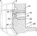
向通孔55输送气体是通过一个或几个定径套管52实现的。定径套管52装在基体51的通孔72内,通孔72倾斜于阀门纵轴线2,自倾斜的基体上部分57的外部轮廓出发,穿过基体51到达通孔下部分68的孔洞69壁处。定径套管52的外部直径与通孔72的直径之间的压配合,使定长套管52不能发生滑动。这些空心圆柱体形的定径套管52有一个贯穿它们的纵向孔洞73。气体就是由此输入。纵向孔洞73的内部横截面加工尺寸十分精确,亦即经过精确校准,它们确定或者说计量流入通孔55的气体量。定径套管52的上端有一个,比方说平的卡圈75,其直径比通孔72的直径大,并紧靠在基体51上部分57的外部轮廓上。本实施例中,定径套管52的整个纵向孔洞73的直径不变。The delivery of gas to the through
计量气体的功能将在一个分离部件中,即在定径套管52的纵向孔洞73内进行,该套管52可以独立于基体51并被制成尺寸精确的构件。在已知的燃料喷射阀上,带有气体输送管道的附加件是一个单个的整体零件。由于对计量截面的尺寸精度要求很高,使加工费用高昂。本发明中的附加件50由多个部件组成(基体51/多件定径套管52),故而做到了功能分散。定径套管做为小型部件,可以用简单的加工方法大量生产,加工成本大为降低。此外,还可以方便地区分用于基体51和定径套管52的材料。例如前面提到的那样,基体51可以是一个塑料的压铸件,也可以是由其他材料构成的。选择基体51的材料时,个别规范要求也退居次要作用了,例如温度敏感性。因此,对附加件50具有更大的造型自由。此外,很容易做到在基体51上配备不同的定径套管52,从而达到多种多样的变化形式,而不必对附加件50做很大改变。The function of metering the gas will take place in a separate part, ie in the
显示有其他结构的附图均集中表现附加件50或者定径套管52的构成形式,并粗略图示燃料喷射阀1及喷咀件5顺流动方向的一个末端。比较图2与图1中的实施例,它们的定径套管的区别在于,纵向孔洞73的孔径宽度沿着介质流动方向是否有所变化。如图2中所示,可见一个台阶77或者一个连续的,无台阶的圆锥形孔洞,而下面的通孔部分68,是一个比方说完整的,顺流动方向扩展的锥形开孔部分。也就是说,它没有射流切分器。此外,基体51的上部分57不完全呈斜形,而是有一个柱形端部78,也就是说基体51的外部轮廓形状稍有变化。The drawings showing other structures all focus on the configuration of the
图3中展示一个附加件50,基体上部分57范围内的外形轮廓走向是垂直的,即平行于阀门轴线2。上部分57的形状为柱状形,并围绕在喷咀件5顺流动方向的一端上,情况如同前面实施例所述。由于附加件上部分57外部轮廓垂直,故这些定径套管52的走向是,比方说,水平的,即与阀门纵轴线2成直角地通向内通孔55,并用卡圈75紧靠在附加件上部分57外部的壁上。这些定径套管52的纵向孔洞73通到了通孔55中部的柱状形通孔部分67,因为附加件的上部分57顺流动方向,在轴向上已延伸到了通孔的中间部分67处。因此向燃料输供气体是在接近喷咀5的喷射孔33附近进行的。FIG. 3 shows an
图4至图7展示其他实施例中的定径套管52,它们的布局方式,比方说如图3中实施例所示,定径套管水平地从附加件的外部57出发,向中间通孔部分67处伸展。图4中所见到的定径套管52实施例中,该管既达不到附加件上部分57的外壁,也达不到附加件中间通孔部分67的孔壁,而是分别在比两侧稍微以内处终止。配合定径套管52的基体通孔72制成为比方说台阶形。这是因为基体51内有一个平台79,因此基体内的通孔72的直径在通向阀门纵轴线2的方向上相应减小。与此相对应的定径套管的外围上,从形状上看也有一个台阶77,这个台阶77与平台79准确地紧靠在一起。在台阶77改变定径套管52的纵向通孔73的径向宽度处,也可把纵向通孔73做成一个向一侧缩小的圆锥形80,使流过它的气体量控制在所需要的量上。Figures 4 to 7 show the sizing
图5中展示的定径套管52有一个使其内部的纵向通孔73的径向宽度减小的台阶77。与此相反,基体通孔72上有一个向一侧减小的锥形81,它反过来又给定了定径套管52的外部轮廓。所以,定径套筒52外部同样有一段是圆锥形的,基锥度与基体通孔72的锥度一致。通往基体中间部分67的通孔72的直径的尺寸,相当于在定径套管52上呈减小的锥形末端的直径大小。The calibrating
图6及图7展示两个由于附加的保险措施而十分牢靠的定径套管52。在压入基体通孔72的定径套管52的外围上可以制作比方说防滑安全措施如凸缘物84或锯齿状的尖角85,它们抓入基体51材料,从而防止定径套管滑动。6 and 7 show two sizing
除以上各实施例外,还设想了其他的变通方案,以下做简单介绍。举例说,变更每一个附加件50上的定径套管52的数目。通常可装一个至六个定径套管52。定径套管52可以直接对着或不对着燃料喷射阀1的喷射孔盘32上的喷射孔33。纵向通孔73的横截面,除上面已提到的圆形外,也可以是方形的、矩形的(缝形的)、椭圆形的或其他形状的,为保证定径套管52在基体通孔72内不发生滑动,可在定径套管52上做个卡圈75 (图1、2、3、6、7)或台阶79(图4)或一个圆锥体(图5)。(定径套管被)挤压的足够有力时,也可考虑不加保险措施的方案。In addition to the above embodiments, other alternative solutions are conceived, which are briefly introduced below. For example, vary the number of sizing
Claims (10)
Applications Claiming Priority (2)
| Application Number | Priority Date | Filing Date | Title |
|---|---|---|---|
| DEP19529375.4 | 1995-08-10 | ||
| DE19529375A DE19529375A1 (en) | 1995-08-10 | 1995-08-10 | Fuel injector |
Publications (2)
| Publication Number | Publication Date |
|---|---|
| CN1158153A true CN1158153A (en) | 1997-08-27 |
| CN1066243C CN1066243C (en) | 2001-05-23 |
Family
ID=7769132
Family Applications (1)
| Application Number | Title | Priority Date | Filing Date |
|---|---|---|---|
| CN96190749A Expired - Fee Related CN1066243C (en) | 1995-08-10 | 1996-07-24 | Fuel injection valve |
Country Status (7)
| Country | Link |
|---|---|
| US (1) | US5904299A (en) |
| EP (1) | EP0786049B1 (en) |
| JP (1) | JPH10507509A (en) |
| KR (1) | KR970706454A (en) |
| CN (1) | CN1066243C (en) |
| DE (2) | DE19529375A1 (en) |
| WO (1) | WO1997006365A1 (en) |
Cited By (3)
| Publication number | Priority date | Publication date | Assignee | Title |
|---|---|---|---|---|
| CN102828875A (en) * | 2012-09-28 | 2012-12-19 | 重庆大学 | Oil-water instantaneous emulsifying injector for diesels |
| CN103154490A (en) * | 2010-10-08 | 2013-06-12 | 株式会社京浜 | Injection valve for gaseous fuel |
| CN113719374A (en) * | 2021-07-29 | 2021-11-30 | 东风商用车有限公司 | Fuel supply channel applied to side jet ignition system |
Families Citing this family (13)
| Publication number | Priority date | Publication date | Assignee | Title |
|---|---|---|---|---|
| US6095437A (en) * | 1998-01-26 | 2000-08-01 | Denso Corporation | Air-assisted type fuel injector for engines |
| DE19857244A1 (en) * | 1998-12-11 | 2000-06-15 | Bosch Gmbh Robert | Fuel injection valve for internal combustion engines |
| DE10059681A1 (en) * | 2000-12-01 | 2002-06-06 | Bosch Gmbh Robert | Method for blowing fuel out of a volume of a fuel injector |
| US6631857B2 (en) | 2000-12-22 | 2003-10-14 | Caterpillar Inc | Partially plastic fuel injector component and method of making the same |
| US6561167B2 (en) * | 2001-02-16 | 2003-05-13 | Synerject, Llc | Air assist fuel injectors |
| DE10319582B4 (en) * | 2003-04-24 | 2007-03-22 | Lechler Gmbh | Binary spray nozzle |
| JP4090972B2 (en) * | 2003-09-19 | 2008-05-28 | 日産ディーゼル工業株式会社 | Engine exhaust purification system |
| DE10358724A1 (en) * | 2003-12-15 | 2005-07-14 | Robert Bosch Gmbh | Fuel injection system for a spark-ignited internal combustion engine comprises a gas channel supplying gas to the fuel downstream of a sealing seat |
| JP4595924B2 (en) * | 2006-02-09 | 2010-12-08 | 株式会社デンソー | Fuel injection valve |
| US8672234B2 (en) | 2010-05-20 | 2014-03-18 | Enginetics, Llc | Multi-physics fuel atomizer and methods |
| JP5811979B2 (en) * | 2012-09-24 | 2015-11-11 | 株式会社デンソー | Fuel injection valve |
| US9518547B2 (en) * | 2015-05-07 | 2016-12-13 | Caterpillar Inc. | Fuel injector including extensions for split spray angles |
| CN109072848A (en) | 2015-10-16 | 2018-12-21 | 秘方能源私人有限公司 | Improve the tradition directly method of injector and improved injector assembly |
Family Cites Families (12)
| Publication number | Priority date | Publication date | Assignee | Title |
|---|---|---|---|---|
| DE3717256A1 (en) * | 1987-05-22 | 1988-12-01 | Seitz Enzinger Noll Masch | METHOD AND DEVICE FOR FILLING CARBONIC LIQUIDS, IN PARTICULAR DRINKS, UNDER BACK PRESSURE IN VESSEL OD. DGL. |
| US4982716A (en) * | 1988-02-19 | 1991-01-08 | Toyota Jidosha Kabushiki Kaisha | Fuel injection valve with an air assist adapter for an internal combustion engine |
| US5035358A (en) * | 1989-03-22 | 1991-07-30 | Toyota Jidosha Kabushiki Kaisha | Fuel injector for use in an engine |
| DE4103918B4 (en) * | 1990-02-15 | 2005-05-04 | Aisan Kogyo K.K., Obu | Multi-hole injection nozzle device |
| DE4009320A1 (en) * | 1990-03-23 | 1991-09-26 | Bosch Gmbh Robert | Device for injecting mixt. of fuel and gas |
| DE4035312A1 (en) * | 1990-11-07 | 1992-05-14 | Bosch Gmbh Robert | DEVICE FOR INJECTING A FUEL-GAS MIXTURE |
| US5218943A (en) * | 1991-01-07 | 1993-06-15 | Toyota Jidosha Kabushiki Kaisha | Fuel injection apparatus for internal combustion engine |
| JP2778292B2 (en) * | 1991-06-06 | 1998-07-23 | トヨタ自動車株式会社 | Fuel injection device for internal combustion engine |
| JP3053934B2 (en) * | 1991-10-31 | 2000-06-19 | 愛三工業株式会社 | Multi-hole injector |
| IT1260961B (en) * | 1993-08-06 | 1996-04-29 | Weber Srl | HIGH ATOMIZATION INJECTOR, IN PARTICULAR FOR THE SUPPLY OF MOTOR VEHICLE ENGINES |
| JPH07103100A (en) * | 1993-08-09 | 1995-04-18 | Mitsubishi Electric Corp | Fuel injection valve |
| US5772122A (en) * | 1995-04-27 | 1998-06-30 | Nippondenso Co., Ltd. | Fuel injection apparatus for an internal combustion engine |
-
1995
- 1995-08-10 DE DE19529375A patent/DE19529375A1/en not_active Ceased
-
1996
- 1996-07-24 JP JP9508008A patent/JPH10507509A/en active Pending
- 1996-07-24 US US08/809,804 patent/US5904299A/en not_active Expired - Fee Related
- 1996-07-24 WO PCT/DE1996/001358 patent/WO1997006365A1/en active IP Right Grant
- 1996-07-24 DE DE59606717T patent/DE59606717D1/en not_active Expired - Fee Related
- 1996-07-24 KR KR1019970702142A patent/KR970706454A/en active IP Right Grant
- 1996-07-24 EP EP96928321A patent/EP0786049B1/en not_active Expired - Lifetime
- 1996-07-24 CN CN96190749A patent/CN1066243C/en not_active Expired - Fee Related
Cited By (4)
| Publication number | Priority date | Publication date | Assignee | Title |
|---|---|---|---|---|
| CN103154490A (en) * | 2010-10-08 | 2013-06-12 | 株式会社京浜 | Injection valve for gaseous fuel |
| US9027859B2 (en) | 2010-10-08 | 2015-05-12 | Keihin Corporation | Gas fuel injection valve |
| CN102828875A (en) * | 2012-09-28 | 2012-12-19 | 重庆大学 | Oil-water instantaneous emulsifying injector for diesels |
| CN113719374A (en) * | 2021-07-29 | 2021-11-30 | 东风商用车有限公司 | Fuel supply channel applied to side jet ignition system |
Also Published As
| Publication number | Publication date |
|---|---|
| EP0786049A1 (en) | 1997-07-30 |
| KR970706454A (en) | 1997-11-03 |
| JPH10507509A (en) | 1998-07-21 |
| DE59606717D1 (en) | 2001-05-10 |
| CN1066243C (en) | 2001-05-23 |
| WO1997006365A1 (en) | 1997-02-20 |
| DE19529375A1 (en) | 1997-02-13 |
| US5904299A (en) | 1999-05-18 |
| EP0786049B1 (en) | 2001-04-04 |
Similar Documents
| Publication | Publication Date | Title |
|---|---|---|
| CN1158153A (en) | Fuel injection valve | |
| KR960003696B1 (en) | Fuel injection valve | |
| US4971254A (en) | Thin orifice swirl injector nozzle | |
| EP1236888B1 (en) | Fluid injection nozzle | |
| US6070812A (en) | Fluid injection valve | |
| US4890794A (en) | Perforated body for a fuel injection valve | |
| US5323966A (en) | Apparatus for injecting a fuel-air mixture | |
| EP1581739B1 (en) | Spray pattern control with non-angled orifices formed on dimpled fuel injection metering disc having a sac volume reducer | |
| US6769625B2 (en) | Spray pattern control with non-angled orifices in fuel injection metering disc | |
| US5044561A (en) | Injection valve for fuel injection systems | |
| US20080006713A1 (en) | Fuel injector having an internally mounted cross-flow nozzle for enhanced compressed natural gas jet spray | |
| US5772122A (en) | Fuel injection apparatus for an internal combustion engine | |
| US7303144B2 (en) | Reduction in hydrocarbon emission via spray pattern control through fuel pressure control in fuel injection systems | |
| US5197672A (en) | Fuel injection valve and adjustable gas sleeve forming an annular metering gas gap | |
| JP2009103035A (en) | Injector | |
| US5826804A (en) | Device for the injection of a fuel/gas mixture | |
| US6851629B2 (en) | Fuel injection valve | |
| JPH08177689A (en) | Fuel supply device for internal combustion engine | |
| CN1109816C (en) | Fuel injection valve | |
| JP2004332657A (en) | Fuel injection valve | |
| CN1054294A (en) | Injection device for fuel/gas mixture | |
| US5191871A (en) | Apparatus for injecting a fuel-gas mixture | |
| JPH02241972A (en) | fuel injection valve | |
| US5161511A (en) | Apparatus for injecting a fuel-gas mixture | |
| EP0745765A1 (en) | Method for influencing the fuel alignment of a fuel injector and fuel injector |
Legal Events
| Date | Code | Title | Description |
|---|---|---|---|
| C06 | Publication | ||
| PB01 | Publication | ||
| C10 | Entry into substantive examination | ||
| SE01 | Entry into force of request for substantive examination | ||
| C14 | Grant of patent or utility model | ||
| GR01 | Patent grant | ||
| C19 | Lapse of patent right due to non-payment of the annual fee | ||
| CF01 | Termination of patent right due to non-payment of annual fee |