CN115813608A - Devices and systems for docking heart valves - Google Patents
Devices and systems for docking heart valves Download PDFInfo
- Publication number
- CN115813608A CN115813608A CN202211107862.5A CN202211107862A CN115813608A CN 115813608 A CN115813608 A CN 115813608A CN 202211107862 A CN202211107862 A CN 202211107862A CN 115813608 A CN115813608 A CN 115813608A
- Authority
- CN
- China
- Prior art keywords
- docking station
- frame
- station frame
- valve
- strut portions
- Prior art date
- Legal status (The legal status is an assumption and is not a legal conclusion. Google has not performed a legal analysis and makes no representation as to the accuracy of the status listed.)
- Pending
Links
Images


Classifications
-
- A—HUMAN NECESSITIES
- A61—MEDICAL OR VETERINARY SCIENCE; HYGIENE
- A61F—FILTERS IMPLANTABLE INTO BLOOD VESSELS; PROSTHESES; DEVICES PROVIDING PATENCY TO, OR PREVENTING COLLAPSING OF, TUBULAR STRUCTURES OF THE BODY, e.g. STENTS; ORTHOPAEDIC, NURSING OR CONTRACEPTIVE DEVICES; FOMENTATION; TREATMENT OR PROTECTION OF EYES OR EARS; BANDAGES, DRESSINGS OR ABSORBENT PADS; FIRST-AID KITS
- A61F2/00—Filters implantable into blood vessels; Prostheses, i.e. artificial substitutes or replacements for parts of the body; Appliances for connecting them with the body; Devices providing patency to, or preventing collapsing of, tubular structures of the body, e.g. stents
- A61F2/02—Prostheses implantable into the body
- A61F2/24—Heart valves ; Vascular valves, e.g. venous valves; Heart implants, e.g. passive devices for improving the function of the native valve or the heart muscle; Transmyocardial revascularisation [TMR] devices; Valves implantable in the body
- A61F2/2409—Support rings therefor, e.g. for connecting valves to tissue
-
- A—HUMAN NECESSITIES
- A61—MEDICAL OR VETERINARY SCIENCE; HYGIENE
- A61F—FILTERS IMPLANTABLE INTO BLOOD VESSELS; PROSTHESES; DEVICES PROVIDING PATENCY TO, OR PREVENTING COLLAPSING OF, TUBULAR STRUCTURES OF THE BODY, e.g. STENTS; ORTHOPAEDIC, NURSING OR CONTRACEPTIVE DEVICES; FOMENTATION; TREATMENT OR PROTECTION OF EYES OR EARS; BANDAGES, DRESSINGS OR ABSORBENT PADS; FIRST-AID KITS
- A61F2/00—Filters implantable into blood vessels; Prostheses, i.e. artificial substitutes or replacements for parts of the body; Appliances for connecting them with the body; Devices providing patency to, or preventing collapsing of, tubular structures of the body, e.g. stents
- A61F2/02—Prostheses implantable into the body
- A61F2/24—Heart valves ; Vascular valves, e.g. venous valves; Heart implants, e.g. passive devices for improving the function of the native valve or the heart muscle; Transmyocardial revascularisation [TMR] devices; Valves implantable in the body
- A61F2/2412—Heart valves ; Vascular valves, e.g. venous valves; Heart implants, e.g. passive devices for improving the function of the native valve or the heart muscle; Transmyocardial revascularisation [TMR] devices; Valves implantable in the body with soft flexible valve members, e.g. tissue valves shaped like natural valves
- A61F2/2418—Scaffolds therefor, e.g. support stents
-
- A—HUMAN NECESSITIES
- A61—MEDICAL OR VETERINARY SCIENCE; HYGIENE
- A61F—FILTERS IMPLANTABLE INTO BLOOD VESSELS; PROSTHESES; DEVICES PROVIDING PATENCY TO, OR PREVENTING COLLAPSING OF, TUBULAR STRUCTURES OF THE BODY, e.g. STENTS; ORTHOPAEDIC, NURSING OR CONTRACEPTIVE DEVICES; FOMENTATION; TREATMENT OR PROTECTION OF EYES OR EARS; BANDAGES, DRESSINGS OR ABSORBENT PADS; FIRST-AID KITS
- A61F2/00—Filters implantable into blood vessels; Prostheses, i.e. artificial substitutes or replacements for parts of the body; Appliances for connecting them with the body; Devices providing patency to, or preventing collapsing of, tubular structures of the body, e.g. stents
- A61F2/02—Prostheses implantable into the body
- A61F2/24—Heart valves ; Vascular valves, e.g. venous valves; Heart implants, e.g. passive devices for improving the function of the native valve or the heart muscle; Transmyocardial revascularisation [TMR] devices; Valves implantable in the body
- A61F2/2427—Devices for manipulating or deploying heart valves during implantation
- A61F2/243—Deployment by mechanical expansion
- A61F2/2433—Deployment by mechanical expansion using balloon catheter
-
- A—HUMAN NECESSITIES
- A61—MEDICAL OR VETERINARY SCIENCE; HYGIENE
- A61F—FILTERS IMPLANTABLE INTO BLOOD VESSELS; PROSTHESES; DEVICES PROVIDING PATENCY TO, OR PREVENTING COLLAPSING OF, TUBULAR STRUCTURES OF THE BODY, e.g. STENTS; ORTHOPAEDIC, NURSING OR CONTRACEPTIVE DEVICES; FOMENTATION; TREATMENT OR PROTECTION OF EYES OR EARS; BANDAGES, DRESSINGS OR ABSORBENT PADS; FIRST-AID KITS
- A61F2220/00—Fixations or connections for prostheses classified in groups A61F2/00 - A61F2/26 or A61F2/82 or A61F9/00 or A61F11/00 or subgroups thereof
- A61F2220/0008—Fixation appliances for connecting prostheses to the body
-
- A—HUMAN NECESSITIES
- A61—MEDICAL OR VETERINARY SCIENCE; HYGIENE
- A61F—FILTERS IMPLANTABLE INTO BLOOD VESSELS; PROSTHESES; DEVICES PROVIDING PATENCY TO, OR PREVENTING COLLAPSING OF, TUBULAR STRUCTURES OF THE BODY, e.g. STENTS; ORTHOPAEDIC, NURSING OR CONTRACEPTIVE DEVICES; FOMENTATION; TREATMENT OR PROTECTION OF EYES OR EARS; BANDAGES, DRESSINGS OR ABSORBENT PADS; FIRST-AID KITS
- A61F2250/00—Special features of prostheses classified in groups A61F2/00 - A61F2/26 or A61F2/82 or A61F9/00 or A61F11/00 or subgroups thereof
- A61F2250/0058—Additional features; Implant or prostheses properties not otherwise provided for
- A61F2250/0096—Markers and sensors for detecting a position or changes of a position of an implant, e.g. RF sensors, ultrasound markers
- A61F2250/0098—Markers and sensors for detecting a position or changes of a position of an implant, e.g. RF sensors, ultrasound markers radio-opaque, e.g. radio-opaque markers
Landscapes
- Health & Medical Sciences (AREA)
- Cardiology (AREA)
- Engineering & Computer Science (AREA)
- Biomedical Technology (AREA)
- Vascular Medicine (AREA)
- Transplantation (AREA)
- Oral & Maxillofacial Surgery (AREA)
- Heart & Thoracic Surgery (AREA)
- Life Sciences & Earth Sciences (AREA)
- Animal Behavior & Ethology (AREA)
- General Health & Medical Sciences (AREA)
- Public Health (AREA)
- Veterinary Medicine (AREA)
- Mechanical Engineering (AREA)
- Prostheses (AREA)
- External Artificial Organs (AREA)
Abstract
Description
相关申请related application
本申请要求于2021年9月17日提交的美国临时专利申请序列号63/245,721和于2022年8月9日提交的美国临时专利申请序列号63/370,870的优先权和所有权益,这两个申请通过引用以其整体并入。This application claims priority to and all benefit of U.S. Provisional Patent Application Serial No. 63/245,721, filed September 17, 2021, and U.S. Provisional Patent Application Serial No. 63/370,870, filed August 9, 2022, both of which The application is incorporated by reference in its entirety.
技术领域technical field
本发明涉及心脏瓣膜,并具体地涉及用于植入心脏瓣膜例如经导管心脏瓣膜(“THV”)的对接站(docking stations)/支架、递送系统和方法。The present invention relates to heart valves, and in particular to docking stations/stents, delivery systems and methods for implanting heart valves, such as transcatheter heart valves ("THVs").
背景技术Background technique
假体心脏瓣膜可用于治疗心脏瓣膜性障碍。天然心脏瓣膜(主动脉瓣、肺动脉瓣、三尖瓣和二尖瓣)在确保充足的血液供应正向流动通过心血管系统中起到关键作用。先天性、炎性或传染性状况可致使这些心脏瓣膜不够有效。此类状况可最终导致严重的心血管危害或死亡。多年来对于此类障碍的决定性治疗是手术修复或在心脏直视手术期间的瓣膜置换。Prosthetic heart valves are used to treat heart valve disorders. The natural heart valves (aortic, pulmonary, tricuspid and mitral) play a key role in ensuring an adequate blood supply and positive flow through the cardiovascular system. Congenital, inflammatory or infectious conditions can render these heart valves less effective. Such conditions can ultimately lead to serious cardiovascular harm or death. For many years the definitive treatment for this disorder has been surgical repair or valve replacement during open heart surgery.
经导管技术还可用于以比心脏直视手术创伤小的方式利用柔性导管引入并植入假体心脏瓣膜。在此技术中,可将假体瓣膜以折绉状态安装在柔性导管的末端部分上并推进通过患者的血管,直到瓣膜到达植入部位。然后可在有缺陷的天然瓣膜部位处将导管尖端处的瓣膜扩张至其功能尺寸,如通过使其上安装了瓣膜的球囊膨胀。可选地,瓣膜可以具有弹性、自扩张支架或框架,在将瓣膜从导管远端处的递送鞘推进时使瓣膜扩张至其功能尺寸。Transcatheter techniques can also be used to introduce and implant prosthetic heart valves using flexible catheters in a less invasive manner than open heart surgery. In this technique, a prosthetic valve may be mounted in a creped state on the end portion of a flexible catheter and advanced through the patient's blood vessel until the valve reaches the implantation site. The valve at the catheter tip can then be expanded to its functional size at the site of the defective native valve, such as by inflating a balloon on which the valve is mounted. Alternatively, the valve may have an elastic, self-expanding stent or frame that expands the valve to its functional size when the valve is advanced from a delivery sheath at the distal end of the catheter.
经导管心脏瓣膜(THV)可以被适当地设定尺寸以被置于大多数天然主动脉瓣内。然而,对于较大的天然瓣膜、血管和移植物,主动脉经导管瓣膜可能太小而不能固定到较大的植入部位或部署部位中。在此情况下,经导管瓣膜可能不足够大以在天然瓣膜或其它植入部位或部署部位内充分扩张以固定就位。Transcatheter heart valves (THVs) can be appropriately sized to be placed within most native aortic valves. However, for larger native valves, vessels and grafts, aortic transcatheter valves may be too small to be secured into larger implantation or deployment sites. In such cases, the transcatheter valve may not be large enough to expand sufficiently within the native valve or other implantation or deployment site to secure in place.
置换肺动脉瓣——其有时被称为肺动脉瓣膜——展现出极大的挑战。肺动脉的几何结构可在患者间变化很大。一般地,矫正手术后的肺动脉流出道对于假体心脏瓣膜的有效放置来说是太宽的。Replacing the pulmonary valve, which is sometimes called the pulmonary valve, presents great challenges. The geometry of the pulmonary arteries can vary widely from patient to patient. Typically, the pulmonary outflow tract after corrective surgery is too wide for effective placement of a prosthetic heart valve.
发明内容Contents of the invention
此概述意图提供示例而不意图以任何方式限制本发明的范围。例如,权利要求不要求此概述的示例中所包括的任何特征,除非权利要求明确叙述了该特征。描述公开了用于可扩张瓣膜的可扩张对接站的示例性实施方式。可以以各种方式构建对接站。This summary is intended to provide an example and is not intended to limit the scope of the invention in any way. For example, the claims do not require any feature included in this summarized example, unless the claim explicitly recites that feature. The description discloses exemplary embodiments of an expandable docking station for an expandable valve. Docking stations can be constructed in various ways.
在一些实施方式中,用于医疗装置的对接站框架包括从近端延伸到远端并形成多个单元的多个支柱部分。In some embodiments, a docking station frame for a medical device includes a plurality of strut portions extending from a proximal end to a distal end and forming a plurality of cells.
在一些实施方式中,当所述对接站框架处于扩张的无约束状态时,所述多个支柱部分形成基本上连续的曲线状纵向廓型(profile),所述基本上连续的曲线状纵向廓型具有在所述近端和所述远端处的外径向保持部分和限定瓣膜座的内径向中心部分。In some embodiments, when the docking station frame is in an expanded, unconstrained state, the plurality of strut portions form a substantially continuous curvilinear longitudinal profile, the substantially continuous curvilinear longitudinal profile The mold has an outer radial retaining portion at said proximal end and said distal end and an inner radial central portion defining a valve seat.
在一些实施方式中,所述多个支柱部分包括多个周向支柱部分和多个纵向支柱部分,所述多个周向支柱部分轴向间隔以限定所述多个单元的多个行,所述多个纵向支柱部分周向间隔并且与所述多个周向支柱联合以限定所述多个行的每一行中所述多个单元中的单元。In some embodiments, the plurality of strut portions includes a plurality of circumferential strut portions and a plurality of longitudinal strut portions, the plurality of circumferential strut portions being axially spaced to define a plurality of rows of the plurality of cells, so The plurality of longitudinal strut portions are circumferentially spaced and associated with the plurality of circumferential struts to define cells of the plurality of cells in each of the plurality of rows.
在一些实施方式中,所述多个周向支柱部分包括限定至少四行所述多个单元的至少五个周向支柱部分。In some embodiments, the plurality of circumferential strut portions includes at least five circumferential strut portions defining at least four rows of the plurality of cells.
在一些实施方式中,其中所述多个纵向支柱部分包括在所述多个行的每一行中限定至少十二个单元的至少十二个纵向支柱部分。In some embodiments, wherein the plurality of longitudinal strut sections includes at least twelve longitudinal strut sections defining at least twelve cells in each of the plurality of rows.
在一些实施方式中,所述多个周向支柱部分包括波状支柱部分。In some embodiments, the plurality of circumferential strut portions includes corrugated strut portions.
在一些实施方式中,并列的波状支柱部分基本上是平行的并且成形为使得所述多个单元中的每一个是基本上人字形的。In some embodiments, the juxtaposed undulating strut portions are substantially parallel and shaped such that each of the plurality of cells is substantially herringbone.
在一些实施方式中,所述并列的波状支柱部分中远侧的一个限定在所述远端处的外径向保持部分,而所述并列的波状支柱部分中近侧的一个限定在所述近端处的外径向保持部分。In some embodiments, a distal one of said juxtaposed undulating strut portions defines an outer radial retaining portion at said distal end, and a proximal one of said juxtaposed undulating strut portions defines an outer radial retaining portion at said proximal end. The outer diameter of the holding part.
在一些实施方式中,所述多个波状支柱部分中的每一个包括与所述多个纵向支柱部分中对应的一个联合的近侧部分,以及不与所述多个纵向支柱部分附接的远侧部分。In some embodiments, each of the plurality of undulating strut portions includes a proximal portion associated with a corresponding one of the plurality of longitudinal strut portions, and a distal portion not attached to the plurality of longitudinal strut portions. side part.
在一些实施方式中,当所述对接站框架处于所述扩张的无约束状态时,腰部具有约27mm的直径并且可扩张以容纳具有约29mm直径的瓣膜。In some embodiments, the waist has a diameter of about 27 mm and is expandable to accommodate a valve having a diameter of about 29 mm when the docking station frame is in the expanded, unconstrained state.
在一些实施方式中,当所述对接站框架处于所述扩张的无约束状态时,所述对接站框架具有约35mm和约40mm之间的长度。In some embodiments, the docking station frame has a length of between about 35 mm and about 40 mm when the docking station frame is in the expanded, unconstrained state.
在一些实施方式中,当所述对接站框架处于所述扩张的无约束状态时,所述保持部分以相对于所述对接站框架的中心纵向轴线约30°和约45°之间的角度延伸。In some embodiments, the retaining portion extends at an angle between about 30° and about 45° relative to a central longitudinal axis of the docking station frame when the docking station frame is in the expanded, unconstrained state.
在一些实施方式中,当所述对接站框架处于所述扩张的无约束状态时,腰部部分是基本上圆柱形的。In some embodiments, the waist portion is substantially cylindrical when the docking station frame is in the expanded, unconstrained state.
在一些实施方式中,当所述对接站框架处于所述扩张的无约束状态时,所述保持部分具有约14mm和约20mm之间的曲率半径。In some embodiments, the retaining portion has a radius of curvature of between about 14 mm and about 20 mm when the docking station frame is in the expanded, unconstrained state.
在一些实施方式中,当所述对接站框架处于所述扩张的无约束状态时,所述内径向中心部分被塑形以为具有29mm的部署外径的瓣膜提供具有至少约8mm长度的瓣膜座。In some embodiments, the inner radially central portion is shaped to provide a valve seat having a length of at least about 8 mm for a valve having a deployed outer diameter of 29 mm when the docking station frame is in the expanded, unconstrained state.
在一些实施方式中,所述对接站框架被配置为折绉到不大于约5.4mm的直径。In some embodiments, the docking station frame is configured to be creased to a diameter of no greater than about 5.4 mm.
在一些实施方式中,当所述对接站框架处于扩张的无约束状态时,所述多个支柱部分在所述近端和所述远端处形成外径向保持部分,所述外径向保持部分以相对于所述对接站框架的中心纵向轴线约30°和约45°之间的角度延伸。In some embodiments, when the docking station frame is in an expanded, unconstrained state, the plurality of strut portions form outer radial retaining portions at the proximal and distal ends, the outer radial retaining portions A portion extends at an angle between about 30° and about 45° relative to a central longitudinal axis of the docking station frame.
在一些实施方式中,当所述对接站框架处于所述扩张的无约束状态时,所述内径向中心部分是基本上圆柱形的。In some embodiments, the inner radially central portion is substantially cylindrical when the docking station frame is in the expanded, unconstrained state.
在一些实施方式中,当所述对接站框架处于扩张的无约束状态时,所述多个支柱部分形成曲线状纵向廓型,所述曲线状纵向廓型具有在所述近端和所述远端处的外径向保持部分和限定瓣膜座的内径向中心部分,所述内径向中心部分是基本上圆柱形的,并且所述外径向保持部分各自具有约14mm和约20mm之间的曲率半径。In some embodiments, when the docking station frame is in an expanded, unconstrained state, the plurality of strut portions form a curvilinear longitudinal profile having An outer radial retaining portion at the end and an inner radial central portion defining a valve seat, the inner radial central portion being substantially cylindrical, and the outer radial retaining portions each having a radius of curvature between about 14mm and about 20mm .
在一些实施方式中,当所述对接站框架处于所述扩张的无约束状态时,所述保持部分具有约44mm的最大直径。In some embodiments, the retaining portion has a maximum diameter of about 44 mm when the docking station frame is in the expanded, unconstrained state.
在一些实施方式中,用于医疗装置的对接站包括对接站框架和不可渗透材料,所述不可渗透材料附接到所述对接站框架。In some embodiments, a docking station for a medical device includes a docking station frame and an impermeable material attached to the docking station frame.
在一些实施方式中,所述不可渗透材料附接到所述瓣膜座以提供所述瓣膜座与安装在所述瓣膜座中的瓣膜之间的密封。In some embodiments, the impermeable material is attached to the valve seat to provide a seal between the valve seat and a valve installed in the valve seat.
在一些实施方式中,所述不可渗透材料在所述内径向中心部分与所述外径向保持部分中的至少一个之间附接到所述对接站框架的中间部分,以提供在所述对接站被部署在循环系统中的部署部位时对所述部署部位密封的中间密封部分。In some embodiments, the impermeable material is attached to an intermediate portion of the docking station frame between at least one of the inner radial center portion and the outer radial retaining portion to provide a An intermediate seal portion that seals the deployment site when the station is deployed at the deployment site in the circulatory system.
在一些实施方式中,系统包括:递送导管,所述递送导管包括管;以及设置在所述管中的对接站。In some embodiments, a system includes: a delivery catheter comprising a tube; and a docking station disposed within the tube.
在一些实施方式中,用于假体瓣膜的对接站包括可扩张对接站框架,所述可扩张对接站框架包括从所述对接站框架的第一端延伸到第二端的多个支柱,其中所述可扩张框架还限定用于将假体瓣膜固定到所述可扩张框架的瓣膜座。In some embodiments, a docking station for a prosthetic valve includes an expandable docking station frame comprising a plurality of struts extending from a first end to a second end of the docking station frame, wherein the The expandable frame also defines a valve seat for securing a prosthetic valve to the expandable frame.
在一些实施方式中,所述对接站框架的所述第一端限定保持部分,所述保持部分可径向向外扩张以在扩张尺寸范围内接合部署位置处循环系统的内表面。In some embodiments, the first end of the docking station frame defines a retaining portion that is expandable radially outward to engage an inner surface of the circulatory system at a deployed site within an expanded dimension.
在一些实施方式中,多个不透射线标记被设置在所述对接站框架的所述第一端周围。In some embodiments, a plurality of radiopaque markers are disposed about the first end of the docking station frame.
在一些实施方式中,所述对接站框架的所述第一端包括所述对接站框架的最末端Z字形部分,所述最末端Z字形部分在外轴向顶点与内轴向接合部之间交替。In some embodiments, said first end of said docking station frame comprises an endmost zigzag portion of said docking station frame, said endmost zigzag portion alternating between outer axial vertices and inner axial junctions .
在一些实施方式中,所述多个不透射线标记中的每一个位于所述内轴向接合部与所述外轴向顶点之间。In some embodiments, each of the plurality of radiopaque markers is located between the inner axial junction and the outer axial apex.
在一些实施方式中,所述多个不透射线标记中的每一个被设置在所述多个外轴向顶点中对应的一个上。In some embodiments, each of the plurality of radiopaque markers is disposed on a corresponding one of the plurality of outer axial vertices.
在一些实施方式中,所述多个不透射线标记中的每一个被附接到所述多个外轴向顶点中所述对应的一个。In some embodiments, each of the plurality of radiopaque markers is attached to the corresponding one of the plurality of outer axial vertices.
在一些实施方式中,所述对接站框架包括多个一体形成的标记安置部分,每个标记安置部分将所述多个不透射线标记中的一个保持在其中。In some embodiments, the docking station frame includes a plurality of integrally formed marker placement portions, each marker placement portion retaining one of the plurality of radiopaque markers therein.
在一些实施方式中,所述对接站包括不可渗透材料,所述不可渗透材料附接到所述对接站框架并且具有设置在所述对接站框架的所述第一端处的第一端部分,其中所述多个不透射线标记中的每一个附连到所述不可渗透材料的所述第一端部分。In some embodiments, the docking station includes an impermeable material attached to the docking station frame and having a first end portion disposed at the first end of the docking station frame, wherein each of the plurality of radiopaque markers is attached to the first end portion of the impermeable material.
在一些实施方式中,所述多个不透射线标记中的每一个与所述对接站框架的所述第一端一体形成。In some embodiments, each of the plurality of radiopaque markers is integrally formed with the first end of the docking station frame.
在一些实施方式中,所述多个不透射线标记包括在所述多个支柱之间的扩大的接合部。In some embodiments, the plurality of radiopaque markers includes enlarged junctions between the plurality of struts.
在一些实施方式中,所述对接站包括第二多个不透射线标记,所述第二多个不透射线标记被设置在所述对接站框架的第二轴向位置周围,与所述对接站框架的所述第一端轴向间隔。In some embodiments, the docking station includes a second plurality of radiopaque markers disposed about a second axial location of the docking station frame in relation to the docking station The first ends of the station frame are axially spaced.
在一些实施方式中,所述第二多个不透射线标记被设置在所述瓣膜座周围。In some embodiments, the second plurality of radiopaque markers are disposed about the valve seat.
在一些实施方式中,所述第二多个不透射线标记被设置在所述对接站框架的所述第二端周围。In some embodiments, the second plurality of radiopaque markers are disposed about the second end of the docking station frame.
在一些实施方式中,所述第二多个不透射线标记被设置在所述对接站框架的所述第二端的外轴向顶点与内轴向接合部之间。In some embodiments, the second plurality of radiopaque markers are disposed between an outer axial apex and an inner axial junction of the second end of the docking station frame.
在一些实施方式中,所述第二多个不透射线标记被设置在所述对接站框架的所述第二端的多个外轴向顶点上。In some embodiments, the second plurality of radiopaque markers are disposed on a plurality of outer axial vertices of the second end of the docking station frame.
在一些实施方式中,所述第二多个不透射线标记被附接到所述对接站框架的所述第二端的所述多个外轴向顶点。In some embodiments, the second plurality of radiopaque markers are attached to the plurality of outer axial vertices of the second end of the docking station frame.
在一些实施方式中,所述对接站框架包括第二多个一体形成的标记安置部分,每个标记安置部分将所述第二多个不透射线标记中的一个保持在其中。In some embodiments, the docking station frame includes a second plurality of integrally formed marker placement portions, each marker placement portion retaining one of the second plurality of radiopaque markers therein.
在一些实施方式中,所述对接站还包括不可渗透材料,所述不可渗透材料附接到所述对接站框架,其中所述第二多个不透射线标记中的每一个附连到所述不可渗透材料。In some embodiments, the docking station further comprises an impermeable material attached to the docking station frame, wherein each of the second plurality of radiopaque markers is attached to the impermeable material.
在一些实施方式中,所述第二多个不透射线标记中的每一个与所述对接站框架一体形成。In some embodiments, each of the second plurality of radiopaque markers is integrally formed with the docking station frame.
在一些实施方式中,所述第二多个不透射线标记包括在所述多个支柱之间的扩大的接合部。In some embodiments, the second plurality of radiopaque markers includes enlarged junctions between the plurality of struts.
在一些实施方式中,所述第一多个不透射线标记中的每一个具有第一构型,并且所述第二多个不透射线标记中的每一个具有不同于所述第一构型的第二构型。In some embodiments, each of the first plurality of radiopaque markers has a first configuration, and each of the second plurality of radiopaque markers has a different configuration than the first configuration. the second configuration of .
在一些实施方式中,所述第二构型在标记尺寸、标记形状、标记取向和相邻标记之间的距离中的至少一项上不同于所述第一构型。In some embodiments, the second configuration differs from the first configuration in at least one of marker size, marker shape, marker orientation, and distance between adjacent markers.
在一些实施方式中,所述瓣膜座被设置在所述对接站框架的在所述第一端与所述第二端之间的中间部分上。In some embodiments, the valve seat is disposed on an intermediate portion of the docking station frame between the first end and the second end.
在一些实施方式中,所述对接站框架限定从所述第一端和所述第二端延伸到较窄的圆柱形或浅凹形腰部部分的凹形廓型。In some embodiments, the docking station frame defines a concave profile extending from the first end and the second end to a narrower cylindrical or shallow concave waist portion.
在一些实施方式中,所对接站框架限定圆柱形外部分,其中所述瓣膜座自所述外部分径向向内偏移。In some embodiments, the docking station frame defines a cylindrical outer portion, wherein the valve seat is offset radially inwardly from the outer portion.
在一些实施方式中,所述对接站框架包括至少一个径向向外延伸的凸缘端部分。In some embodiments, the docking station frame includes at least one radially outwardly extending flange end portion.
在一些实施方式中,所述对接站框架包括凸形廓型的第一端部分和第二端部分以及限定所述瓣膜座的凹形腰部部分。In some embodiments, the docking station frame includes first and second end portions of a convex profile and a concave waist portion defining the valve seat.
在一些实施方式中,所述对接站框架包括扩口的第一端部分和第二端部分以及限定所述瓣膜座的凹形腰部部分。In some embodiments, the docking station frame includes flared first and second end portions and a concave waist portion defining the valve seat.
在一些实施方式中,在将假体瓣膜安装在血管中的方法中,可扩张对接站框架,如,例如本文描述的任意对接站框架以压缩状态被提供在第一管内。将所述第一管插入所述血管中。从所述第一管部署所述对接站,并在所述血管内的目标位置处扩张所述对接站框架,使得所述对接站框架的第一端径向扩张到所述瓣膜座外侧以接合所述血管的内表面,从而将所述对接站框架保持在所述目标位置处。从所述血管撤回所述第一管。可扩张假体瓣膜以压缩状态被提供在第二管内。将所述第二管插入所述血管中,并将所述第二管的终端延伸到扩张后的对接站框架的所述第一端中。从所述第二管的所述终端部署所述可扩张假体瓣膜,并将所述假体瓣膜扩张成与所述扩张后的对接站框架的瓣膜座就座接合(seating engagement)。In some embodiments, in a method of installing a prosthetic valve in a blood vessel, an expandable docking station frame, such as, for example, any of the docking station frames described herein is provided in a compressed state within a first tube. The first tube is inserted into the blood vessel. Deploy the docking station from the first tube and expand the docking station frame at a target location within the blood vessel such that the first end of the docking station frame expands radially outside the valve seat to engage the inner surface of the blood vessel, thereby maintaining the docking station frame at the target location. The first tube is withdrawn from the blood vessel. An expandable prosthetic valve is provided within the second tube in a compressed state. Inserting the second tube into the blood vessel and extending a terminal end of the second tube into the first end of the expanded docking station frame. The expandable prosthetic valve is deployed from the terminal end of the second tube and expands the prosthetic valve into seating engagement with a valve seat of the expanded docking station frame.
在一些实施方式中,通过视觉上识别设置在所述对接站框架的所述第一端周围的多个不透射线标记,在视觉上确认所述扩张后的对接站框架的所述第一端的位置布置。In some embodiments, the first end of the expanded docking station frame is visually identified by visually identifying a plurality of radiopaque markers disposed about the first end of the docking station frame location layout.
在一些实施方式中,所述对接站还包括第二多个不透射线标记,所述第二多个不透射线标记被设置在所述对接站框架的第二轴向位置周围,与所述对接站框架的所述第一端轴向间隔。In some embodiments, the docking station further includes a second plurality of radiopaque markers disposed about a second axial location of the docking station frame in relation to the The first ends of the docking station frame are axially spaced.
在一些实施方式中,从所述第一管部署所述对接站框架并在所述血管内的所述目标位置处扩张所述对接站框架包括,从所述第一管部分地部署所述对接站框架并在从所述第一管完全地部署所述对接站框架之前在视觉上确认所述第二多个不透射线标记在所述目标位置处的位置。In some embodiments, deploying the docking station frame from the first tube and expanding the docking station frame at the target location within the blood vessel comprises partially deploying the docking station frame from the first tube and visually confirming the location of the second plurality of radiopaque markers at the target location prior to fully deploying the docking station frame from the first tube.
在一些实施方式中,所述第二多个不透射线标记被设置在所述瓣膜座周围,并且从所述第二管的所述终端部署所述可扩张假体瓣膜包括,在完全地部署所述可扩张假体瓣膜之前在视觉上确认与所述可扩张假体瓣膜对准的所述第二多个不透射线标记的位置。In some embodiments, the second plurality of radiopaque markers are disposed about the valve seat, and deploying the expandable prosthetic valve from the terminal end of the second tube comprises, upon fully deploying The expandable prosthetic valve previously visually confirms a position of the second plurality of radiopaque markers aligned with the expandable prosthetic valve.
在一些实施方式中,所述假体瓣膜和所述第二管终端中的至少一个包括至少一个不透射线标记,其中在视觉上确认与所述可扩张假体瓣膜对准的所述第二多个不透射线标记的位置包括,在视觉上确认与所述至少一个不透射线标记对准的所述第二多个不透射线标记的位置。In some embodiments, at least one of the prosthetic valve and the second tube terminal end includes at least one radiopaque marker, wherein the second tube end in alignment with the expandable prosthetic valve is visually confirmed. Positioning the plurality of radiopaque markers includes visually confirming a position of the second plurality of radiopaque markers aligned with the at least one radiopaque marker.
上述方法(一种或多种)可以在活体动物上或在模拟物上如在尸体、尸体心脏、模拟器(例如,模拟身体部位、心脏、小叶、组织等)上执行。The method(s) described above can be performed on a living animal or on a simulated object such as a cadaver, a cadaveric heart, a simulator (eg, simulated body part, heart, lobules, tissue, etc.).
本公开中别处描述的各种特征可以被包括在此处概括的示例中,并且可利用使用这些示例和特征的各种方法和步骤,包括本文别处所描述的。Various features described elsewhere in this disclosure can be included in the examples outlined herein, and various methods and steps using these examples and features can be utilized, including those described elsewhere herein.
所公开的发明的本质和优点的进一步理解可通过以下描述和权利要求获得,特别是在与相同部分具有相同参考编号的所附附图一起考虑时。A further understanding of the nature and advantages of the disclosed invention may be gained from the following description and claims, especially when considered in conjunction with the accompanying drawings, in which like parts have like reference numerals.
附图说明Description of drawings
为进一步阐明本公开实施方式的各种方面,将通过参考所附附图的各种方面作出某些实施方式的更具体的描述。应当理解这些附图仅描绘了本公开的一般实施方式并因此不被认为是限制本公开的范围。此外,尽管针对一些实施方式按比例绘制了附图,但是不必要针对所有实施方式都按比例绘制附图。本公开的实施方式将通过利用所附附图以另外的特异性和细节来描述和说明。To further clarify various aspects of the embodiments of the present disclosure, a more particular description of certain embodiments will be made by reference to various aspects of the accompanying drawings. It should be understood that the drawings depict only typical embodiments of the disclosure and therefore are not to be considered as limiting the scope of the disclosure. Furthermore, although the figures are drawn to scale for some embodiments, the figures are not necessarily drawn to scale for all embodiments. Embodiments of the present disclosure will be described and illustrated with additional specificity and detail by use of the accompanying drawings.
图1A是处于舒张期的人心脏的剖面图;Figure 1A is a cross-sectional view of a human heart in diastole;
图1B是处于收缩期的人心脏的剖面图;Figure 1B is a cross-sectional view of a human heart in systole;
图2A和图2B是图示了肺动脉可以具有各种不同形状和尺寸的肺动脉截面图;2A and 2B are cross-sectional views of pulmonary arteries illustrating that pulmonary arteries can have various shapes and sizes;
图3A和图3B是图示了肺动脉可以具有各种不同形状和尺寸的肺动脉透视图;3A and 3B are perspective views of pulmonary arteries illustrating that pulmonary arteries can have various shapes and sizes;
图4A是被定位在循环系统中的压缩的对接站的示意图;Figure 4A is a schematic diagram of a compressed docking station positioned in a circulation system;
图4B是被扩张以将对接站的位置设定在循环系统中的图4A的对接站的示意图;4B is a schematic illustration of the docking station of FIG. 4A expanded to position the docking station in the circulation system;
图4C是被定位在图4B图示的对接站中的可扩张经导管心脏瓣膜的示意图;Figure 4C is a schematic illustration of an expandable transcatheter heart valve positioned in the docking station illustrated in Figure 4B;
图4D是被扩张以将心脏瓣膜的位置设定在对接站中的图4C的经导管心脏瓣膜的示意图;4D is a schematic illustration of the transcatheter heart valve of FIG. 4C expanded to position the heart valve in the docking station;
图5A是对接站部署在肺动脉中的处于收缩期的人心脏的剖面图;5A is a cross-sectional view of a human heart in systole with the docking station deployed in the pulmonary artery;
图5B是对接站和经导管心脏瓣膜部署在肺动脉中的处于收缩期的人心脏的剖面图;5B is a cross-sectional view of a human heart in systole with a docking station and a transcatheter heart valve deployed in the pulmonary artery;
图6A是在心脏处于收缩期时图5B的对接站和经导管心脏瓣膜的放大示意图;Figure 6A is an enlarged schematic view of the docking station and transcatheter heart valve of Figure 5B when the heart is in systole;
图6B是沿图6A中的线6B-6B指示的方向截取的视图;Figure 6B is a view taken along the direction indicated by
图7是对接站和经导管心脏瓣膜部署在肺动脉中的处于舒张期的人心脏的剖面图;7 is a cross-sectional view of a human heart in diastole with a docking station and a transcatheter heart valve deployed in the pulmonary artery;
图8A是在心脏处于舒张期时图7的对接站和经导管心脏瓣膜的放大示意图;Figure 8A is an enlarged schematic illustration of the docking station and transcatheter heart valve of Figure 7 when the heart is in diastole;
图8B是沿图8A中的线8B-8B指示的方向截取的视图;Figure 8B is a view taken along the direction indicated by
图9A是对接站的框架的示例性实施方式的侧视图;Figure 9A is a side view of an exemplary embodiment of a frame of a docking station;
图9B图示了图9A的框架的侧面廓型;Figure 9B illustrates the side profile of the frame of Figure 9A;
图9C是图9A的框架的端视图;Figure 9C is an end view of the frame of Figure 9A;
图9D是图9A的框架的透视图;Figure 9D is a perspective view of the frame of Figure 9A;
图10是具有附接到可扩张框架的不可渗透材料的对接站的示例性实施方式的侧视图;Figure 10 is a side view of an exemplary embodiment of a docking station having an impermeable material attached to an expandable frame;
图11A和图11B示意性地图示了当植入在循环系统的不同尺寸的血管中时图10所图示的对接站的侧面廓型;11A and 11B schematically illustrate the side profile of the docking station illustrated in FIG. 10 when implanted in different sized blood vessels of the circulatory system;
图12是图示了置于肺动脉中的对接站和置于对接站中的示意性图示的瓣膜的示例性实施方式的侧面廓型的截面图;12 is a cross-sectional view illustrating a docking station positioned in a pulmonary artery and a side profile of an exemplary embodiment of a schematically illustrated valve positioned in the docking station;
图13A是对接站部署在肺动脉中的处于收缩期的人心脏的剖面图;13A is a cross-sectional view of a human heart in systole with the docking station deployed in the pulmonary artery;
图13B是对接站部署在肺动脉中的处于收缩期的人心脏的剖面图;13B is a cross-sectional view of a human heart in systole with the docking station deployed in the pulmonary artery;
图13C是对接站和经导管心脏瓣膜部署在肺动脉中的处于收缩期的人心脏的剖面图;13C is a cross-sectional view of a human heart in systole with a docking station and a transcatheter heart valve deployed in the pulmonary artery;
图14-图17和图18A-图18C图示了可被部署在对接站例如本文描述或描绘的其中一个对接站中的瓣膜类型的示例;14-17 and 18A-18C illustrate examples of valve types that may be deployed in a docking station, such as one of the docking stations described or depicted herein;
图19A是根据一个实施方式的具有框架和不可渗透材料的对接站的侧视图;Figure 19A is a side view of a docking station with a frame and impermeable material according to one embodiment;
图19B是根据另一实施方式的具有框架和不可渗透材料的对接站的侧视图;Figure 19B is a side view of a docking station with a frame and impermeable material according to another embodiment;
图19C是根据另一实施方式的具有框架和不可渗透材料的对接站的侧视图;Figure 19C is a side view of a docking station with a frame and impermeable material according to another embodiment;
图19D是根据另一实施方式的具有框架和不可渗透材料的对接站的侧视图;以及19D is a side view of a docking station with a frame and impermeable material according to another embodiment; and
图20是包括沙漏形框架和附接的不可渗透密封材料的对接站的透视图;20 is a perspective view of a docking station including an hourglass-shaped frame and an attached impermeable sealing material;
图21是示例性可扩张框架的局部视图,示出了可扩张框架的示例性第一端、第二端和中心单元;21 is a partial view of an exemplary expandable frame showing an exemplary first end, second end, and central unit of the expandable frame;
图21A是沿着由图21的线21A-21A指示的平面截取的图21可扩张框架的纵向支柱的第一端部分的横截面图;21A is a cross-sectional view of a first end portion of a longitudinal strut of the expandable frame of FIG. 21 taken along the plane indicated by
图21B是沿着由图21的线21B-21B指示的平面截取的图21可扩张框架的纵向支柱的第二端部分的横截面图;21B is a cross-sectional view of the second end portion of the longitudinal strut of the expandable frame of FIG. 21 taken along the plane indicated by line 21B-21B of FIG. 21;
图21C是沿着由图21的线21C-21C指示的平面截取的图21可扩张框架的纵向支柱的中心部分的横截面图;21C is a cross-sectional view of the central portion of the longitudinal struts of the expandable frame of FIG. 21 taken along the plane indicated by
图21D是沿着由图21的线21D-21D指示的平面截取的图21可扩张框架的周向支柱的第一端部分的横截面图;21D is a cross-sectional view of the first end portion of the circumferential strut of the expandable frame of FIG. 21 taken along the plane indicated by
图21E是沿着由图21的线21E-21E指示的平面截取的图21可扩张框架的周向支柱的第二端部分的横截面图;21E is a cross-sectional view of the second end portion of the circumferential strut of the expandable frame of FIG. 21 taken along the plane indicated by
图21F是沿着由图21的线21F-21F指示的平面截取的图21可扩张框架的周向支柱的中心部分的横截面图;21F is a cross-sectional view of the central portion of the circumferential struts of the expandable frame of FIG. 21 taken along the plane indicated by
图22是具有从扩口端部分延伸到较窄腰部部分的凹形廓型的示例性对接站框架的侧视图;22 is a side view of an exemplary docking station frame having a concave profile extending from a flared end portion to a narrower waist portion;
图22A是具有圆柱形外框架部分和径向向内偏移的瓣膜座部分的示例性对接站框架的侧视图;22A is a side view of an exemplary docking station frame having a cylindrical outer frame portion and a radially inwardly offset valve seat portion;
图22B是具有圆柱形外框架部分和径向向内偏移的瓣膜座部分的另一示例性对接站框架的侧视图;22B is a side view of another exemplary docking station frame having a cylindrical outer frame portion and a radially inwardly offset valve seat portion;
图22C是具有从细长圆柱形部分的一端延伸的径向向外延伸的柔性凸缘部分的示例性对接站框架的侧视图;22C is a side view of an exemplary docking station frame having a radially outwardly extending flexible flange portion extending from one end of the elongated cylindrical portion;
图22D是具有从细长圆柱形部分的两端延伸的径向向外延伸的柔性凸缘部分的示例性对接站框架的侧视图;22D is a side view of an exemplary docking station frame having radially outwardly extending flexible flange portions extending from both ends of the elongated cylindrical portion;
图22E是具有含凸形端部分的沙漏形廓型的示例性对接站框架的侧视图;22E is a side view of an exemplary docking station frame having an hourglass-shaped profile with convex end portions;
图22F是具有含扩口端部分的沙漏形廓型的示例性对接站框架的侧视图;22F is a side view of an exemplary docking station frame having an hourglass-shaped profile with flared end portions;
图23A是安装的对接站的示例性血管接合廓型的示意性侧横截面图,在保持部分和密封部分之间具有径向间隙,并且在对接站腰部部分周围具有径向间隙;23A is a schematic side cross-sectional view of an exemplary vessel engagement profile of the docking station installed, with a radial gap between the retaining portion and the sealing portion, and a radial gap around the docking station waist portion;
图23B是安装的对接站的另一示例性血管接合廓型的示意性侧横截面图,其中对接站的凹形廓型在对接站腰部部分周围提供径向间隙;23B is a schematic side cross-sectional view of another exemplary vessel engagement profile of the docking station installed, wherein the concave profile of the docking station provides radial clearance around the waist portion of the docking station;
图23C是安装的对接站的另一示例性血管接合廓型的示意性侧横截面图,其中对接站的凹形廓型与血管内表面连续接触;23C is a schematic side cross-sectional view of another exemplary vessel engagement profile of the docking station installed, wherein the concave profile of the docking station is in continuous contact with the inner surface of the vessel;
图23D是安装的对接站的另一示例性血管接合廓型的示意性侧横截面图,其中对接站的圆柱形廓型与基本上圆柱形的血管内表面连续接触;23D is a schematic side cross-sectional view of another exemplary vessel engagement profile of the docking station installed, wherein the cylindrical profile of the docking station is in continuous contact with the substantially cylindrical inner surface of the vessel;
图23E是安装的对接站的另一示例性血管接合廓型的示意性侧横截面图,其中对接站的柔性圆柱形廓型与非均匀的血管内表面连续接触;23E is a schematic side cross-sectional view of another exemplary vessel engagement profile of the docking station installed, wherein the flexible cylindrical profile of the docking station is in continuous contact with a non-uniform inner vessel surface;
图23F是安装的对接站的另一示例性血管接合廓型的示意性侧横截面图,在末端部分处切向接合并且在对接站的腰部部分周围具有径向间隙;23F is a schematic side cross-sectional view of another exemplary vessel engagement profile of the docking station installed, tangentially engaged at the tip portion and with radial clearance around the waist portion of the docking station;
图24A是安装的对接站的示例性血管接合廓型的示意性侧横截面图,示出了对接站框架的末端部分从对接站框架的中心开口径向向内变形;24A is a schematic side cross-sectional view of an exemplary vessel engagement profile of an installed docking station showing an end portion of the docking station frame deformed radially inward from a central opening of the docking station frame;
图24B是图24A的安装的对接站的示意性端视图;Figure 24B is a schematic end view of the mounted docking station of Figure 24A;
图25A是根据一个实施方式的不透射线标记的前透视图;Figure 25A is a front perspective view of a radiopaque marker according to one embodiment;
图25B是根据另一个实施方式的不透射线标记的前透视图;Figure 25B is a front perspective view of a radiopaque marker according to another embodiment;
图25C是根据另一个实施方式的不透射线标记的前透视图;Figure 25C is a front perspective view of a radiopaque marker according to another embodiment;
图25D是根据另一个实施方式的不透射线标记的前透视图;Figure 25D is a front perspective view of a radiopaque marker according to another embodiment;
图26是具有从扩口端部分延伸到较窄腰部部分的凹形廓型的示例性对接站框架的侧视图,其中不透射线标记附连到框架的第一端;26 is a side view of an exemplary docking station frame having a concave profile extending from a flared end portion to a narrower waist portion, with a radiopaque marker attached to a first end of the frame;
图26A是具有圆柱形外框架部分和径向向内偏移的瓣膜座部分的示例性对接站框架的侧视图,其中不透射线标记附连到框架的第一端;26A is a side view of an exemplary docking station frame having a cylindrical outer frame portion and a radially inwardly offset valve seat portion, with a radiopaque marker attached to a first end of the frame;
图26B是具有圆柱形外框架部分和径向向内偏移的瓣膜座部分的另一示例性对接站框架的侧视图,其中不透射线标记附连到框架的第一端;26B is a side view of another exemplary docking station frame having a cylindrical outer frame portion and a radially inwardly offset valve seat portion, with a radiopaque marker attached to a first end of the frame;
图26C是具有从细长圆柱形部分的一端延伸的径向向外延伸的柔性凸缘部分的示例性对接站框架的侧视图,其中不透射线标记附连到框架的第一端;26C is a side view of an exemplary docking station frame having a radially outwardly extending flexible flange portion extending from one end of the elongated cylindrical portion, with a radiopaque marker attached to the first end of the frame;
图26D是具有从细长圆柱形部分的两端延伸的径向向外延伸的柔性凸缘部分的示例性对接站框架的侧视图,其中不透射线标记附连到框架的第一端;26D is a side view of an exemplary docking station frame having radially outwardly extending flexible flange portions extending from both ends of the elongated cylindrical portion, with a radiopaque marker attached to a first end of the frame;
图26E是具有含凸形端部分的沙漏形廓型的示例性对接站框架的侧视图,其中不透射线标记附连到框架的第一端;26E is a side view of an exemplary docking station frame having an hourglass-shaped profile with a convex end portion, with a radiopaque marker attached to a first end of the frame;
图26F是具有含扩口端部分的沙漏形廓型的示例性对接站框架的侧视图,其中不透射线标记附连到框架的第一端;26F is a side view of an exemplary docking station frame having an hourglass-shaped profile with a flared end portion, with a radiopaque marker attached to a first end of the frame;
图27是具有从扩口端部分延伸到较窄腰部部分的凹形廓型的示例性对接站框架的侧视图,其中不透射线标记附连到固定到框架的第一端的材料;27 is a side view of an exemplary docking station frame having a concave profile extending from a flared end portion to a narrower waist portion, with a radiopaque marker attached to material secured to a first end of the frame;
图27A是具有圆柱形外框架部分和径向向内偏移的瓣膜座部分的示例性对接站框架的侧视图,其中不透射线标记附连到固定到框架的第一端的材料;27A is a side view of an exemplary docking station frame having a cylindrical outer frame portion and a radially inwardly offset valve seat portion with a radiopaque marker attached to material secured to a first end of the frame;
图27B是具有圆柱形外框架部分和径向向内偏移的瓣膜座部分的另一示例性对接站框架的侧视图,其中不透射线标记附连到固定到框架的第一端的材料;27B is a side view of another exemplary docking station frame having a cylindrical outer frame portion and a radially inwardly offset valve seat portion with a radiopaque marker attached to material secured to a first end of the frame;
图27C是具有从细长圆柱形部分的一端延伸的径向向外延伸的柔性凸缘部分的示例性对接站框架的侧视图,其中不透射线标记附连到附接到框架的第一端的材料;27C is a side view of an exemplary docking station frame having a radially outwardly extending flexible flange portion extending from one end of an elongated cylindrical portion with a radiopaque marker attached to the first end attached to the frame s material;
图27D是具有从细长圆柱形部分的两端延伸的径向向外延伸的柔性凸缘部分的示例性对接站框架的侧视图,其中不透射线标记附连到固定到框架的第一端的材料;27D is a side view of an exemplary docking station frame having a radially outwardly extending flexible flange portion extending from both ends of the elongated cylindrical portion with a radiopaque marker attached to the first end secured to the frame s material;
图27E是具有含凸形端部分的沙漏形廓型的示例性对接站框架的侧视图,其中不透射线标记附连到固定到框架的第一端的材料;27E is a side view of an exemplary docking station frame having an hourglass-shaped profile with a convex end portion, with a radiopaque marker attached to material secured to a first end of the frame;
图27F是具有含扩口端部分的沙漏形廓型的示例性对接站框架的侧视图,其中不透射线标记附连到固定到框架的第一端的材料;27F is a side view of an exemplary docking station frame having an hourglass-shaped profile with a flared end portion, with a radiopaque marker attached to material secured to a first end of the frame;
图28A是对接站部署在肺动脉中的处于收缩期的人心脏的剖面图;28A is a cross-sectional view of a human heart in systole with the docking station deployed in the pulmonary artery;
图28B是对接站部署在肺动脉中的处于收缩期的人心脏的剖面图;28B is a cross-sectional view of a human heart in systole with the docking station deployed in the pulmonary artery;
图28C是对接站部署在肺动脉中并且经导管心脏瓣膜部署在肺动脉中的处于收缩期的人心脏的剖面图;以及28C is a cross-sectional view of a human heart in systole with the docking station deployed in the pulmonary artery and the transcatheter heart valve deployed in the pulmonary artery; and
图28D是对接站部署在肺动脉中并且经导管心脏瓣膜部署在肺动脉中的处于收缩期的人心脏的剖面图。28D is a cross-sectional view of a human heart in systole with a docking station deployed in the pulmonary artery and a transcatheter heart valve deployed in the pulmonary artery.
具体实施方式Detailed ways
以下描述参考图示了本发明的具体实施方式的所附附图。具有不同结构和操作的其它实施方式不偏离本发明的范围。本公开的示例性实施方式涉及用于为经导管心脏瓣膜(“THV”)提供对接站或着陆区(landing zone)的装置和方法。在一些示例性实施方式中,用于THV的对接站被示例用于肺动脉内,但是对接站可用于解剖结构、心脏或脉管系统的其它区域如上腔静脉或下腔静脉中。此外,本文中的技术和方法可以在活体动物上或在模拟物上如在尸体、尸体心脏、模拟器(例如,模拟身体部位、心脏、组织等)上执行。本文描述的对接站可以被配置为补偿比这样的空间(例如,解剖结构/脉管系统,等等)小的被部署的THV:所述空间中将放置所述THV。The following description refers to the accompanying drawings that illustrate specific embodiments of the invention. Other embodiments having different structures and operations do not depart from the scope of the present invention. Exemplary embodiments of the present disclosure relate to devices and methods for providing a docking station or landing zone for a transcatheter heart valve ("THV"). In some exemplary embodiments, the docking station for THV is exemplified for use within the pulmonary artery, but the docking station may be used in other regions of the anatomy, heart or vasculature such as the superior or inferior vena cava. In addition, the techniques and methods herein can be performed on live animals or on simulations such as on cadavers, cadaver hearts, simulators (eg, simulated body parts, hearts, tissues, etc.). The docking stations described herein may be configured to compensate for a deployed THV being smaller than the space (eg, anatomy/vasculature, etc.) in which the THV will be placed.
应当注意,本文公开了用于递送和植入的对接站和系统的各种实施方式,并且可作出这些选项的任意组合,除非具体排除。例如,公开的任何对接站装置都可与任何类型的瓣膜和/或任何递送系统一起使用,即使未明确描述具体的组合。同样地,可诸如通过组合任意对接站类型/特征、瓣膜类型/特征、组织覆盖物等来混合并匹配对接站和瓣膜的不同构造,即使未明确公开。简言之,可组合所公开系统的各个构件,除非相互排斥或不然在物理上无可能。It should be noted that various embodiments of docking stations and systems for delivery and implantation are disclosed herein, and that any combination of these options can be made unless specifically excluded. For example, any docking station device disclosed can be used with any type of valve and/or any delivery system, even if a specific combination is not explicitly described. Likewise, different configurations of docking stations and valves can be mixed and matched, such as by combining arbitrary docking station types/features, valve types/features, tissue coverings, etc., even if not explicitly disclosed. In short, the various components of the disclosed systems may be combined unless mutually exclusive or otherwise physically impossible.
出于一致的目的,在本申请的这些图和其它中描绘对接站使得肺分叉端(pulmonary bifurcation end)在上,而心室端在下。这些方向也被称为“远侧”,作为上或肺分叉端的同义词,和被称为“近侧”,作为下或心室端的同义词,其是相对于医师视角的术语。For consistency purposes, the docking stations are depicted in these figures and others in this application with the pulmonary bifurcation end on top and the ventricular end on bottom. These directions are also referred to as "distal," as a synonym for the upper or pulmonary bifurcation, and "proximal," as a synonym for the inferior or ventricular end, which are terms relative to the physician's perspective.
图1A和图1B分别是处于舒张期和收缩期的人心脏H的剖面图。右心室RV和左心室LV分别通过三尖瓣TV和二尖瓣MV;即房室瓣,与右心房RA和左心房LA隔开。另外,主动脉瓣AV将左心室LV与升主动脉(未标识)隔开,而肺动脉瓣PV将右心室与肺动脉PA隔开。肺动脉瓣PV设置在肺动脉PA的入口或起点212处。这些瓣膜中的每一个都具有向内延伸横跨各自孔口的柔性小叶,其在流动流(flowstream)中汇集在一起或“对合”形成单向的阻塞流体的平面。本申请的对接站和瓣膜主要关于肺动脉瓣进行描述。因此,将更详细地说明右心房RA和右心室RV的解剖结构。应当理解本文描述的装置还可用于其它区域中,例如,在下腔静脉IVC和/或上腔静脉SVC中作为反流或以其它方式有缺陷的三尖瓣的治疗、在主动脉(例如,扩大的主动脉)中作为有缺陷的主动脉瓣AV的治疗、用于心脏或脉管系统的其它区域中、用于移植物中等等。1A and 1B are cross-sectional views of a human heart H in diastole and systole, respectively. The right ventricle RV and left ventricle LV are separated from the right atrium RA and left atrium LA by the tricuspid valve TV and mitral valve MV, respectively; the atrioventricular valve. Additionally, the aortic valve AV separates the left ventricle LV from the ascending aorta (not shown), while the pulmonary valve PV separates the right ventricle from the pulmonary artery PA. The pulmonary valve PV is positioned at the entrance or
右心房RA通过上腔静脉SVC和下腔静脉IVC接收来自静脉系统的脱氧血,前者从上方进入右心房,而后者从下方进入右心房。冠状窦CS是合并在一起的静脉的聚集,形成聚集来自心脏肌肉(心肌)的脱氧血并将其递送至右心房RA的大血管。在舒张期或心脏舒张期间,图1A中所见,在右心房RA中聚集的静脉血液通过右心室RV的扩张进入三尖瓣TV。在收缩期或心脏收缩期间,图1B中所见,右心室RV收缩以迫使静脉血液通过肺动脉瓣PV和肺动脉PA进入肺中。在一个示例性实施方式中,本申请所描述的装置用于置换或补充有缺陷的肺动脉瓣PV的功能。在心脏收缩期间,三尖瓣TV的小叶闭合以防止静脉血液反流回右心房RA中。The right atrium RA receives deoxygenated blood from the venous system through the superior vena cava SVC and the inferior vena cava IVC, the former entering the right atrium from above and the latter entering the right atrium from below. The coronary sinus CS is a collection of veins that merge together to form the great vessels that collect deoxygenated blood from the heart muscle (myocardium) and deliver it to the right atrium RA. During diastole, or diastole, seen in Figure 1A, venous blood pooled in the right atrium RA enters the tricuspid valve TV through dilation of the right ventricle RV. During systole, or systole, seen in Figure IB, the right ventricle RV contracts to force venous blood through the pulmonary valve PV and pulmonary artery PA into the lungs. In an exemplary embodiment, the devices described herein are used to replace or supplement the function of a defective pulmonary valve PV. During systole, the leaflets of the tricuspid valve TV close to prevent reflux of venous blood into the right atrium RA.
参考图2A-图2B和图3A-图3B,所示的非穷尽示例图示了肺动脉可以具有广泛多种不同的形状和尺寸。例如,如图2A和图2B的截面图和图3A和图3B的透视图中所示,长度、直径以及曲率或轮廓在不同患者的肺动脉之间可变化很大。此外,直径沿个体的肺动脉的长度可显著变化。这些差异在遭受某些状况和/或已受到先前手术的损伤的肺动脉中可能甚至更显著。例如,法鲁四联症(TOF)或大动脉错位(TGA)的治疗时常导致更大的且更不规则形状的肺动脉。Referring to FIGS. 2A-2B and 3A-3B , the non-exhaustive examples shown illustrate that pulmonary arteries can have a wide variety of different shapes and sizes. For example, as shown in the cross-sectional views of FIGS. 2A and 2B and the perspective views of FIGS. 3A and 3B , the length, diameter, and curvature or profile can vary widely between pulmonary arteries in different patients. Furthermore, the diameter can vary significantly along the length of an individual's pulmonary artery. These differences may be even more pronounced in pulmonary arteries that have suffered from certain conditions and/or have been damaged by previous surgery. For example, treatment of tetralogy of Faro (TOF) or transposition of the great arteries (TGA) often results in larger and more irregularly shaped pulmonary arteries.
法鲁四联症(TOF)是一种心脏异常,其指代通常一起发生的四种相关心脏缺陷的组合。这四种缺陷是室间隔缺损(VSD)、主动脉骑跨(主动脉瓣被扩大并表现出从左心室和右心室两者上升而非如正常心脏中从左心室上升)、肺动脉瓣狭窄(肺动脉瓣和流出道或产生血流从右心室至肺动脉的阻碍的瓣膜下方区域的缩窄)和右心室肥大(右心室的肌肉壁的增厚,其发生是因为右心室以高压泵送)。Tetralogy of Faro (TOF) is a cardiac abnormality that refers to a combination of four related heart defects that often occur together. The four defects are ventricular septal defect (VSD), aortic overriding (the aortic valve is enlarged and appears to rise from both the left and right ventricles rather than from the left ventricle as in a normal heart), pulmonary stenosis ( Narrowing of the pulmonary valve and outflow tract or the subvalvular area that creates obstruction of blood flow from the right ventricle to the pulmonary artery) and right ventricular hypertrophy (thickening of the muscle wall of the right ventricle, which occurs because the right ventricle pumps at high pressure).
大动脉错位(TGA)指代主动脉和肺动脉自其正常位置被“转位”致使主动脉从右心室上升而肺动脉从左心室上升的异常。Transposition of the great arteries (TGA) refers to an abnormality in which the aorta and pulmonary artery are "transposed" from their normal positions such that the aorta ascends from the right ventricle and the pulmonary artery ascends from the left ventricle.
某些状况的手术治疗涉及沿肺动脉、上至以及沿肺动脉分支中的一个的纵向切口。此切口可消除或显著损害肺动脉瓣的功能。经瓣环补片(trans-annular patch)用于手术后覆盖切口。经瓣环补片减少与其它手术相关的肺动脉PA的狭窄或受约束的状况。然而,肺动脉瓣PV的损害或消除可产生显著的反流,并且在本发明以前,时常需要后期心脏直视手术置换肺动脉瓣。经瓣环补片技术可导致肺动脉具有宽泛程度的尺寸和形状变化(参见图3A和图3B)。Surgical treatment of certain conditions involves a longitudinal incision along, up to, and along one of the branches of the pulmonary artery. This incision can eliminate or significantly impair the function of the pulmonary valve. A trans-annular patch is used to cover the incision after surgery. Transannular patches reduce narrowing or constriction of the pulmonary artery PA associated with other procedures. However, damage or elimination of the pulmonary valve PV can produce significant regurgitation, and prior to the present invention, late stage open heart surgery was often required to replace the pulmonary valve. The transannular patch technique can result in a wide range of size and shape variations in the pulmonary artery (see Figures 3A and 3B).
参考图4A-图4D,在一个示例性实施方式中,可扩张对接站10包括一个或多个密封部分410、瓣膜座18和一个或多个保持部分414。一个或多个密封部分410在对接站10和循环系统的内表面416之间提供密封。瓣膜座18在对接站10被植入循环系统中后提供用于将瓣膜29植入或部署在对接站10中的支撑表面。保持部分414协助将对接站10和瓣膜29保持在循环系统中的植入位置或部署部位。本文各种实施方式中描述的可扩张对接站10和瓣膜29还表示可能已知或已开发的各种对接站和/或瓣膜,例如,各种不同类型的瓣膜可替换成和/或用作各种对接站中的瓣膜29。Referring to FIGS. 4A-4D , in an exemplary embodiment,
图4A-图4D示意地图示了循环系统中对接站10和瓣膜29的示例性部署。参考图4A,对接站10处于压缩形式/构型并且被引入循环系统中的部署部位。例如,可通过导管(例如,在共同拥有的美国专利申请公开号2019/0000615和美国专利号10,363,130中描述的一个或多个导管,这两者的整个公开内容通过引用并入本文)将对接站10定位在肺动脉中的部署部位。参考图4B,对接站10在循环系统中被扩张,使得一个或多个密封部分410和保持部分414接合循环系统的一部分的内表面416。参考图4C,在部署对接站10后,瓣膜29处于压缩形式并被引入对接站的瓣膜座18中。参考图4D,瓣膜29在对接站10中被扩张,使得瓣膜接合瓣膜座18。在本文描述的示例中,对接站10长于瓣膜29。然而,在其它实施方式中,对接站10的长度可与瓣膜29的长度相同或短于瓣膜29的长度。类似地,瓣膜座18的长度可长于瓣膜29的长度、短于瓣膜29的长度或与其相同。4A-4D schematically illustrate exemplary deployment of
参考图4D,瓣膜29已经扩张,使得对接站的座18支撑瓣膜。对接站10允许瓣膜29在扩张直径范围内工作,瓣膜29是关于该扩张直径范围设计的。Referring to Figure 4D, the
在示例性实施方式中,对接站10被配置为沿其长度径向向外扩张至不同程度以共形于内表面416的形状。在一个示例性实施方式中,对接站10被配置为使得一个或多个密封部分410和/或一个或多个保持部分接合内表面416,虽然血管或心脏的解剖结构的形状沿对接站的长度显著变化。对接站可由非常弹性或顺应性材料制成以适应解剖结构中的大变动。例如,对接站10可由高柔性金属、金属合金或聚合物制成。可使用的金属和金属合金的示例包括,但不限于,镍钛诺、埃尔吉洛伊非磁性合金和不锈钢,但可以使用其它金属和高弹性或顺应性非金属材料。例如,对接站10可以具有由这些材料例如由形状记忆材料如镍钛诺制成的框架或框架的部分(例如,自扩张框架、一个或多个保持部分、一个或多个密封部分、瓣膜座等)。这些材料允许框架被压缩至小尺寸,然后在压缩力释放时,框架将自扩张回到其压缩前直径。本文描述的对接站可自扩张和/或可用可膨胀装置扩张以使对接站接合具有可变形状的内表面416。In an exemplary embodiment,
参考图5A,对接站,例如,如关于图4A-图4D描述的对接站,被部署在心脏H的肺动脉PA中。图5B图示了部署在图5A图示的对接站10中的瓣膜29。在图6A和图6B中,心脏处于收缩期。图6A是肺动脉PA中的对接站10和瓣膜29的放大示意性表示。当心脏处于收缩期时,瓣膜29打开。血液从右心室RV流动并如箭头602指示通过肺动脉PA、对接站10和瓣膜29。图6B图示了血液填充的空间608,其表示瓣膜29在心脏处于收缩期时是开放的。图6B未显示对接站10与肺动脉之间的界面以简化附图。图6B中的交叉影线图示了通过打开的瓣膜的血流。在示例性实施方式中,一个或多个密封部分410防止血液在肺动脉PA和对接站10之间流动,并且瓣膜29在对接站10的座18中的就座(seating)防止血液在对接站10和瓣膜29之间流动。在此示例中,血液在心脏处于收缩期时基本上只流动通过或只能流动通过瓣膜29。Referring to FIG. 5A , a docking station, eg, as described with respect to FIGS. 4A-4D , is deployed in the pulmonary artery PA of the heart H. Referring to FIG. Figure 5B illustrates the
图7图示了在心脏处于舒张期时图5B图示的瓣膜29、对接站10和心脏H。参考图8A和图8B,在心脏处于舒张期时,瓣膜29闭合。图8A是图7的肺动脉中的对接站10和瓣膜29的放大的示意性表示。瓣膜29上方的肺动脉PA中的(即肺动脉分支760中的)血流被闭合的并且阻塞如箭头900指示的血流的瓣膜29阻塞。图8B中的实心区域912表示在心脏处于舒张期时瓣膜29被闭合。Figure 7 illustrates the
在一个示例性实施方式中,对接站10充当防止或基本上防止瓣膜29的径向向外的力被转移至循环系统的内表面416的隔离器。在一个实施方式中,对接站10包括瓣膜座18(其不被THV或瓣膜29的径向向外的力径向向外扩张或基本上不被THV或瓣膜29的径向向外的力径向向外扩张,即瓣膜座的直径不被THV的力增加或被THV的力增加小于约4mm)以及锚定/保持部分414和密封部分410,(相比于瓣膜29对瓣膜座18施加的径向向外的力)其在循环系统的内表面416上仅赋予相对小的径向向外的力720、722。In one exemplary embodiment, the
在不使用对接站时,THV的支架和框架通过直接作用在循环系统的内表面416上的THV的支架或框架712的相对高的径向向外的力710保持在循环系统中就位。如果使用对接站,如在图6A图示的示例中,瓣膜29的支架或框架712径向向外扩张或被径向向外扩张以在对接站10的瓣膜座18上赋予高的力710。此高的径向向外的力710将瓣膜29固定到对接站10的瓣膜座18。然而,由于瓣膜座18不被力710扩张或基本上不被力710扩张,因此力710与循环系统隔离,而非用于使对接站固定在循环系统中。When the docking station is not in use, the THV's stent and frame are held in place in the circulatory system by the relatively high radially outward force 710 of the THV's stent or
在示例性实施方式中,密封部分410对内表面416的径向向外的力722远远小于瓣膜29对瓣膜座18施加的径向向外的力710。例如,径向向外的密封力722可小于瓣膜施加的径向向外的力710的1/2、小于瓣膜施加的径向向外的力710的1/3、小于瓣膜施加的径向向外的力710的1/4、小于瓣膜施加的径向向外的力710的1/8,或甚至小于瓣膜施加的径向向外的力710的1/10。在一个示例性实施方式中,密封部分410的径向向外的力722被选择以在内表面416和密封部分410之间提供密封,但不足以通过其自身保持瓣膜29和对接站10在循环系统中的位置。In the exemplary embodiment, the radially
在示例性实施方式中,锚定/保持部分414对内表面416的径向向外的力720远远小于瓣膜29对瓣膜座18施加的径向向外的力710。例如,径向向外的密封力720可小于瓣膜施加的径向向外的力710的1/2、小于瓣膜施加的径向向外的力710的1/3、小于瓣膜施加的径向向外的力710的1/4、小于瓣膜施加的径向向外的力710的1/8,或甚至小于瓣膜施加的径向向外的力710的1/10。In an exemplary embodiment, the radially
在一个示例性实施方式中,保持部分414的径向向外的力720不足以通过其自身保持瓣膜29和对接站10在循环系统中的位置。而是,血液608的压力用于增强保持部分414保持至内表面416。再次参考图6A,当心脏处于收缩期时,瓣膜29是打开的并且血液如通过箭头602指示流动通过瓣膜。由于瓣膜29是打开的并且血液流动通过瓣膜29,因此血液向对接站10和瓣膜29施加的压力P——如图6A中的小箭头P指示——是低的。虽然小,但是压力P大致沿箭头F指示的方向迫使对接站及其上保持部分414抵靠表面416。此径向向外指向的血流协助的由保持部分414向表面416施加的力F阻碍对接站10和瓣膜29在心脏H的收缩期中沿血流的方向602移动。In one exemplary embodiment, the radially
参考图8A,当心脏处于舒张期时,瓣膜29被闭合并且如箭头900指示血流被阻塞。由于瓣膜29被闭合并且瓣膜29和对接站10阻塞血液流动,因此由血液向对接站10和瓣膜29施加的压力P——如图8A中大箭头P指示——是高的。此大压力P迫使下保持部分414大致沿由大箭头F指示的方向抵靠表面416。此径向向外指向的血流协助的由保持部分414向表面416施加的力F防止对接站10和瓣膜29沿箭头900指示的方向移动。Referring to FIG. 8A , when the heart is in diastole,
由于上和下保持部分414所施加的力取决于由血液向瓣膜29和对接站10施加的压力的量,因此向表面416施加的力自然而然成比例。即,上保持部分在心脏处于收缩期时压靠表面416的力小于下保持部分在心脏处于舒张期时压靠表面416的力。这是因为对处于收缩期的打开的瓣膜29和对接站10的压力小于对处于舒张期的闭合的瓣膜和对接站的压力。Since the force applied by the upper and
瓣膜座18、密封部分410和保持部分414可采取广泛多种不同的形式。例如,瓣膜座18可以是不被THV的径向向外的力径向向外扩张或基本上不被THV的径向向外的力径向向外扩张(例如,当瓣膜部署在瓣膜座中时扩张1-4mm大)并且可以例如在扩张上受固定到对接站10的较窄腰部部分或与对接站10的较窄腰部部分成一体的带(例如,缝线、刚性环)限制的任何结构。在一个这样的示例中,扩张的框架1500可以限定具有约27mm(例如,约27.1mm)的直径的瓣膜座,该瓣膜座扩张到约29mm的直径以适应具有约29mm的部署后的扩张直径的瓣膜29。
密封部分410可以例如由对接站10的较宽部分(即,相对于较窄腰部部分)限定,被提供有密封材料,如,例如附接到对接站或与对接站成一体的织物、泡沫或生物相容性组织。The sealing
保持部分414可以例如由对接站框架的扩口端限定,所述扩口端成角度以与循环系统的内表面416锚定接合。The retaining
共同拥有的美国专利号10,363,130(“’130专利”)(其全部公开内容通过引用并入本文)描述并示出了包括由金属支柱部分的栅格形成的可扩张框架的若干个示例性对接站。图20图示了来自‘130专利的一个这样的示例性对接站10a,包括:由支柱部分1502a的栅格形成的大致沙漏形框架1500a,支柱部分1502a具有由带20a约束的中心部分以提供限定瓣膜座18a的窄腰部部分16a;具有附接的不可渗透材料21a以限定组织接合密封部分410a的凸形轮廓的中间部分17a;以及向外扩口端部分13a,其中最末端单元1504a的顶点1510a限定成角度抵靠循环系统的内表面锚定的向外扩口保持部分414a。Commonly owned U.S. Patent No. 10,363,130 (the "'130 patent"), the entire disclosure of which is incorporated herein by reference, describes and illustrates several exemplary docking stations comprising an expandable frame formed from a grid of metal strut sections . FIG. 20 illustrates one such
根据本发明的一个方面,限定中心腰部部分、中间密封部分和外保持部分的对接站框架可以形成有基本上连续的曲线状纵向廓型,从而提供从中心腰部部分到外端处的最大框架直径的基本上平滑的过渡。如本文所用,“基本上连续的曲线状”廓型可以包括(a)在近端和远端之间且横跨腰部部分具有连续的曲率半径的廓型,以及(b)具有从近端和远端中的每一个朝向中心腰部部分增加的曲率半径,以提供更平坦的腰部部分和更尖锐地成角度的末端部分的廓型。在一些实施方式中,曲率半径可从近端和远端中的每一个朝向基本上圆柱形(即,具有无限大或接近无限大的曲率半径)的中心腰部部分逐渐地或直接地过渡。According to one aspect of the present invention, the docking station frame defining the central waist portion, the intermediate sealing portion and the outer retaining portion may be formed with a substantially continuous curved longitudinal profile providing a maximum frame diameter from the central waist portion to the outer ends A substantially smooth transition. As used herein, a "substantially continuous curvilinear" profile may include (a) a profile with a continuous radius of curvature between the proximal and distal ends and across the waist portion, and (b) a profile with Each of the distal ends has an increasing radius of curvature towards the central waist portion to provide a flatter waist portion and a more sharply angled tip portion profile. In some embodiments, the radius of curvature may transition gradually or directly from each of the proximal and distal ends toward a substantially cylindrical (ie, having an infinite or near infinite radius of curvature) central waist portion.
在一些应用中,这些类型的基本上连续的曲线状纵向廓型可以通过使型面轮廓角(profile contour angle)的离散或局部变化最小来减少框架上的局部应力集中,例如,以提高对接站框架支柱部分的抗断裂性。在一个这样的实施方式中,基本上连续的向外曲线状或凹形纵向廓型的大半径可以提供更长的腰部区域(和更长的所得到的瓣膜座),和/或框架顶点处的减小的角,例如,以限制或防止对所接合的组织穿孔或穿透。In some applications, these types of substantially continuous curvilinear longitudinal profiles can reduce local stress concentrations on the frame by minimizing discrete or local variations in profile contour angles, for example, to improve docking station Fracture resistance of frame strut sections. In one such embodiment, the large radius of the substantially continuous outwardly curved or concave longitudinal profile can provide a longer waist region (and a longer resulting valve seat), and/or The reduced angle, for example, to limit or prevent perforation or penetration of the engaged tissue.
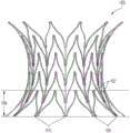
图9A-图9D图示了对接站10的框架1500或主体的示例性实施方式。框架1500或主体可以采用各种不同的形式,而图9A-图9D仅图示了多种可能构型中的一种。在图9A-图9D和图10图示的示例中,对接站10具有相对较宽的近侧流入端12和远侧流出端14,以及在近(例如,流入)端12和远(例如,流出)14之间形成瓣膜座18的相对较窄部分16。在图9A-图9D图示的示例中,对接站10的框架1500优选地是由形成封闭空间并限定单元1504的金属支柱部分1501、1502的栅格所构成的宽支架。在图9A-图9D的示例中,框架1500具有围绕其圆周总体上凹形的纵向廓型,其限定了当在近端12和远端14之间被不可渗透材料覆盖时形成瓣膜座18的相对较窄(与外端相比)的圆柱形或浅中心部分16。如下所述,在使用时,瓣膜29与形成瓣膜座18的较窄中心部分16对准并在较窄中心部分16中扩张。9A-9D illustrate an exemplary embodiment of a
图9A-图9D图示了处于其无约束的扩张状态的框架1500。在此示例性实施方式中,保持部分414包括金属支柱部分1502在近(例如,流入)端12和远(例如,流出)14处的末端或顶点1510(由下面描述的接合部1503、1505形成)。密封部分410中间地设置在保持部分414和较窄中心部分16之间。在无约束状态下,保持部分414总体上径向且轴向向外延伸(例如,以相对于中心轴线约20°和约60°之间,或约30°和约45°之间,或约45°的角度)延伸并且在密封部分410的径向外侧。9A-9D illustrate the
对接站可由非常弹性或非常顺应性材料制成以适应解剖结构中的大变动。例如,对接站可由高柔性金属、金属合金、聚合物或开孔泡沫制成。高弹性金属的示例是镍钛诺,但可以使用其它金属和高弹性或高顺应性非金属材料。对接站框架1500可自扩张、可手动扩张(例如,可经由球囊扩张)或可机械扩张。自扩张对接站框架1500可由形状记忆材料诸如——例如,镍钛诺——制成。在示例性实施方式中,无约束保持部分414延伸到约41mm的外径,并且足够柔性以接合并保持在具有约27mm和约38mm之间的直径的循环系统血管中。The docking station can be made of very elastic or very compliant material to accommodate large changes in anatomy. For example, docking stations can be made from highly flexible metals, metal alloys, polymers, or open-cell foams. An example of a highly elastic metal is Nitinol, but other metals and highly elastic or compliant non-metallic materials can be used. The
在图示的实施方式中,对接站框架1500形成有基本上连续的曲线状纵向廓型,从而提供从中心腰部部分16到外端12、14处的最大框架直径的基本上平滑的过渡。在一些应用中,这种类型的基本上连续的曲线状纵向廓型可以通过使型面轮廓角的离散或局部变化最小来减少框架1500上的局部应力集中,例如,以提高对接站框架支柱部分1501、1502的抗断裂性。在一个这样的实施方式中,向外曲线状或凹形纵向廓型可以提供更长的中心腰部区域16,以及更长的所得到的瓣膜座18。例如,圆柱形或浅凹形中心腰部部分16可以在约29mm的部署后的瓣膜直径下提供至少约8mm,或约9mm和约10mm之间的有效瓣膜座长度。所得到的纵向廓型的大的向外曲线状或凹形长度可以另外地或可选地提供框架1500的顶点1510处的减小的角,例如,以限制或防止对保持部分414所接合的组织穿孔或穿透。例如,当处于扩张的无约束状态时,框架1500的顶点1510可以以相对于框架的纵向轴线约20°和约60°之间,或约30°和约45°之间,或约45°的角度α延伸。在示例性实施方式中,窄腰部部分16具有约3mm至约6mm,或约4mm至约5mm,或约4mm的圆柱形长度,其(逐渐地或直接地)过渡到外端12、14处约14mm和约20mm之间,或约19mm的曲率半径。In the illustrated embodiment, the
对接站10的框架1500可以被设定尺寸、成形和/或以其它方式配置为适配变化的尺寸、形状、直径和几何形状的肺动脉。对接站10的框架1500可以具有任意数量的支柱部分1502、任意数量的单元1504或任意数量的顶点1510,或者支柱部分1501、1502或单元1504可以具有任意形状以适配变化的尺寸、形状和几何形状的肺动脉。支柱部分1501、1502可具有任意尺寸、形状、厚度或构型以将瓣膜29保持在肺动脉PA中。另外,框架1500的近端12可以具有与框架1500的远端14不同的尺寸、形状和/或构型。
如图9A所示,框架1500可以具有从框架的近端12延伸到远端14的高度H和座直径SD,座直径SD是瓣膜座18的直径。框架1500还可以具有密封宽度SW,密封宽度SW是密封部分410的在近端12和瓣膜座18之间对接站10对肺动脉密封的点处的宽度。As shown in FIG. 9A ,
对接站10的框架1500可以具有不同行数的单元1504。可以确定行的数量和构型以提供对接站10在肺动脉PA中更好的固定、适配或贴附(apposition)。例如,对于更长的肺动脉PA或者在更大的径向力有益的情况下,对接站10可以包括更多行的单元1504。The
对接站10的框架1500可以被配置用于宽肺动脉PA。例如,对接站10的框架1500可以被配置用于短且宽的肺动脉PA。在一个这样的示例中,框架1500可以具有32mm和45mm之间——诸如约35mm和约40mm之间,诸如约38mm——的高度H。示例性框架1500可以具有23mm和32mm之间——诸如约26mm和29mm之间,诸如约27mm——的座直径SD。示例性框架可以具有39mm和50mm之间——诸如约41mm——的末端直径。框架1500可以具有36mm和46mm之间——诸如约38mm和44mm之间,诸如约41mm——的密封宽度SW。
对接站10的框架1500还可以被配置为适配较长和/或较宽的肺动脉。例如,对接站10的框架1500可以更长和更宽。在一个这样的示例中,对接站10的框架1500可以具有43mm和53mm之间——诸如约45mm和约51mm之间,诸如约48mm——的高度H。框架1500可以具有24mm和31mm之间——诸如约26mm和约29mm之间,诸如约27mm——的座直径SD。框架1500可以具有44mm和54mm之间——诸如约46mm和约52mm之间,诸如约48mm或约50mm——的密封宽度SW。
虽然框架1500已经被描述为具有人字形单元1504,但是框架还可以具有可选的构型或几何形状,使得框架1500不具有人字形单元1504或不是所有的单元1504都是人字形的。Although the
图10图示了包括具有不可渗透材料21的框架1500的对接站10,不可渗透材料21附接到框架1500以形成对接站10的瓣膜座18和密封部分410,如下面更详细描述的。在一些实施方式中,框架1500可被提供成在腰部部分中不具有限制带,而是依赖于纵向框架廓型的内径向部分的固有刚度和柔性限制。在其它实施方式中,框架可以被提供有被配置为加强和约束窄腰部部分16的带,如上文并入的‘130专利中公开并且本文中图20中示出的。在一个这样的实施方式中,用于将不可渗透材料21附接到框架1500的腰部部分16的缝线可以另外地作为腰部加强/增强带而发挥作用。Figure 10 illustrates
根据本公开的另一示例性方面,框架支柱1501、1502可以被配置为在周向宽度和/或径向厚度上变化,以提供增加或减小的柔性和/或增加或减小的径向力以供保持部分414和内表面IS之间以及瓣膜座18和瓣膜之间所期望地接合。在一个这样的实施方式中,如图21和图21A-图21F所示,可扩张框架1500的支柱1501、1502可以具有远侧第一端部分1501-1、1502-1(限定远端或第一端单元1504-1)、第二端或近侧部分1501-2、1502-2(限定近端或第二端单元1504-2)和中心部分1501-3、1502-3(限定中心单元1504-3),远侧第一端部分1501-1、1502-1具有第一横截面积,第二端或近侧部分1501-2、1502-2具有第二横截面积,中心部分1501-3、1502-3具有第三横截面积。在图示的示例中,中心支柱部分1501-3、1502-3的第三横截面积大于第一端支柱部分1501-1、1502-1的第一横截面积和第二端支柱部分1501-2、1502-2的第二横截面积(其可以但不必基本相同)。中心支柱部分1501-3、1502-3的较大横截面积可以在框架1500的中心部分处提供减小的柔性(例如,以将瓣膜座腰部部分与部署部位隔离)和增加的径向力(例如,以牢固地保持就座的瓣膜),而第一端支柱部分1501-1、1502-1和第二端支柱部分1501-2、1502-2的较小横截面积可以在近端部分和远端部分处提供增加的柔性(例如,以共形于部署部位处的内表面轮廓)和减小但足够的径向力(例如,以最小化或防止保持部分414对组织的损伤),例如,以维持至少约25牛顿的慢性扩张力(COF)供框架1500充分锚定在部署部位处,同时维持柔性以与部署部位处组织的轮廓相顺应。According to another exemplary aspect of the present disclosure, frame struts 1501, 1502 may be configured to vary in circumferential width and/or radial thickness to provide increased or decreased flexibility and/or increased or decreased radial The force is provided for the desired engagement between the retaining
如图所示,中心支柱部分1501-3、1502-3可以具有比远侧支柱部分1501-1、1502-1的厚度t1-1、t2-1和/或近侧支柱部分1501-2、1502-2的厚度t1-2、t2-2更大的径向厚度t1-3、t2-3和/或比远侧支柱部分1501-1、1502-1的宽度w1-1、w2-1和/或近侧支柱部分1501-2、1502-2的宽度w1-2、w2-2更大的周向宽度w1-3、w2-3。例如,周向宽度w1-3、w2-3可以是宽度w1-1、w2-1和/或w1-2、w2-2的110%至300%,诸如宽度w1-1、w2-1和/或w1-2、w2-2的110%至130%,诸如宽度w1-1、w2-1和/或w1-2、w2-2的约115%至约120%。在示例性实施方式中,中心支柱部分1501-3、1502-3可以具有约0.29mm的周向宽度w1-3、w2-3,而远侧支柱部分1501-1、1502-1和/或近侧支柱部分1501-2、1502-2可以具有约0.24mm的周向宽度w1-1、w2-1和/或w1-2、w2-2。作为另一示例,中心支柱部分1501-3、1502-3可以具有约0.39mm的周向宽度w1-3、w2-3,而远侧支柱部分1501-1、1502-1和/或近侧支柱部分1501-2、1502-2可以具有约0.34mm的周向宽度w1-1、w2-1和/或w1-2、w2-2。同样地,径向厚度t3-1、t3-2可以是厚度t1-1、t2-1和/或t1-2、t2-2的110%至300%,诸如厚度t1-1,t2-1和/或t1-2,t2-2的110%至130%,,诸如厚度t1-1,t2-1和/或t1-2,t2-2的115%至120%。在其它实施方式中,支柱部分的周向宽度可以如上所述的那样变化,其中支柱部分的径向厚度是基本上恒定的,例如,以促进由具有均匀壁厚的管形成框架栅格。As shown, central strut portion 1501-3, 1502-3 may have a thickness t 1-1 , t 2-1 than distal strut portion 1501-1, 1502-1 and/or proximal strut portion 1501-2. , 1502-2 thickness t 1-2 , t 2-2 greater radial thickness t 1-3 , t 2-3 and/or width w 1- than distal strut portion 1501-1, 1502-1 1 , w 2-1 and/or the greater circumferential width w 1-3 , w 2-3 of the width w 1-2 , w 2-2 of the proximal strut portion 1501 -2 , 1502-2. For example, the circumferential width w 1-3 , w 2-3 may be 110% to 300% of the width w 1-1 , w 2-1 and/or w 1-2 , w 2-2 , such as the width w 1- 1 , w 2-1 and/or w 1-2 , w 2-2 110% to 130%, such as width w 1-1 , w 2-1 and/or w 1-2 , w 2-2 115% to about 120%. In an exemplary embodiment, central strut portions 1501-3, 1502-3 may have a circumferential width w 1-3 , w 2-3 of about 0.29 mm, while distal strut portions 1501-1, 1502-1 and/or Or the proximal strut portions 1501-2, 1502-2 may have a circumferential width w 1-1 , w 2-1 and/or w 1-2 , w 2-2 of about 0.24 mm. As another example, central strut portions 1501-3, 1502-3 may have a circumferential width w 1-3 , w 2-3 of about 0.39 mm, while distal strut portions 1501-1, 1502-1 and/or proximal Side strut portions 1501-2, 1502-2 may have a circumferential width w 1-1 , w 2-1 and/or w 1-2 , w 2-2 of about 0.34 mm. Likewise, radial thickness t 3-1 , t 3-2 may be 110% to 300% of thickness t 1-1 , t 2-1 and/or t 1-2 , t 2-2 , such as thickness t 1 -1 , t 2-1 and/or t 1-2 , 110% to 130% of t 2-2 , such as thickness t 1-1 , t 2-1 and/or t 1-2 , t 2-2 115% to 120%. In other embodiments, the circumferential width of the strut portions may vary as described above, wherein the radial thickness of the strut portions is substantially constant, for example, to facilitate the formation of a frame grid from tubes of uniform wall thickness.
不可扩张或基本上不可扩张的瓣膜座可以防止瓣膜的径向向外的力转移至循环系统的内表面。然而在另一示例性实施方式中,部署的对接站的腰部/瓣膜座可在瓣膜抵靠其部署时任选地以弹性方式略微地扩张。腰部/瓣膜座的这种任选的弹性扩张可在瓣膜上施加压力以帮助保持瓣膜在对接站内就位。A non-expandable or substantially non-expandable valve seat prevents the radially outward force of the valve from being transferred to the inner surface of the circulatory system. Yet in another exemplary embodiment, the waist/valve seat of the deployed docking station may optionally elastically expand slightly when the valve is deployed against it. This optional elastic expansion of the waist/valve seat can exert pressure on the valve to help keep the valve in place within the docking station.
对接站框架的支柱部分可以被配置为形成各种栅格图案和单元形状,如,例如,图20的实施方式和上文并入的‘130专利中公开的实施方式的基本上菱形的单元构型。在图9A-图9D和图10所示的示例中,对接站框架1500具有栅格框架布置,栅格框架布置包括:轴向间隔的多行波状周向支柱部分或梯级1502,以限定近侧接合部1503和远侧接合部1505的平行Z字形图案布置;和周向间隔的纵向支柱部分或花键1501,沿近侧接合部1503纵向延伸以限定成行的基本上人字形的单元1504。近侧接合部1503和远侧接合部1505可以被配置为充当铰链以使框架1500径向向外偏置成与周围组织接合。波状周向支柱部分1502的远侧接合部1505是未附接的或者“不含”纵向支柱部分1501,允许这些远侧接合部的向外挠曲以在植入时促进(例如,远侧保持部分414和一个或多个密封部分410处的)脉管系统组织接合,从而阻止植入的框架1500向前远侧移动,如下面更详细地讨论的。与近侧接合部1503的竖直支柱的附接限制单元在近侧接合部处向外挠曲,以促进框架1500缩回到折绉或压缩尺寸(例如,以便收回到导管中),例如,缩回到小于约7mm或约5.4mm的直径,其中在完全折绉直径下径向阻力有限(例如,小于60N)。每一端处的保持部分414可以具有基本上相同的最大直径(例如,约42mm和约45mm之间,或约44mm)。在其它实施方式中,由于远侧接合部1505的未附接状态,框架1500的远端或流出端14在扩张的无约束状态下可以具有略微较大的直径。The strut portions of the docking station frame can be configured to form various grid patterns and cell shapes, such as, for example, the substantially diamond-shaped cell structures of the embodiment of FIG. 20 and the embodiments disclosed in the '130 patent incorporated above. type. In the example shown in FIGS. 9A-9D and 10 , the
框架1500可以包括任意合适行数的单元1504(例如,至少三行或至少四行或至少五行)和每行任意合适数量的单元(例如,至少十个,或至少十二个)。在图示的示例中,框架1500包括限定四行单元1504的五个波状周向支柱部分1502和限定每行十二个单元1504的十二个纵向支柱部分1501。通过采用人字形单元布置,可以在框架的长度内提供更多数量的周向支柱部分1502(以及所得到的成行的单元)(例如,与菱形单元布置相比),例如,以增加框架1500的强度,以提供高的装置保持力、抗压性和/或更低的径向向外力(例如,以维持装置完整性,同时使组织损伤最小)。另外地或可选地,框架1500可以以更短的长度(例如,对于被设定尺寸以供植入在肺动脉中的对接站而言,长度约35-40mm)提供,同时仍然提供足够的框架强度。更多数量的纵向支柱部分1501(以及所得到的每行单元)可以例如在使框架1500的形状共形于循环系统中部署部位的形状方面提供增加的柔性。
可以经由常规手段如通过球囊扩张或机械扩张或通过自扩张将瓣膜29递送至对接站的部位。在瓣膜29被扩张时,其嵌套在对接站10的瓣膜座中。在一个实施方式中,腰部部分16略微具有弹性并对瓣膜29施加弹力,以帮助保持瓣膜就位。
图11A和图11B图示了对接站10可用于适应各种不同尺寸的循环系统解剖结构以供具有一致尺寸的瓣膜29植入。在图11A和图11B的示例中,相同尺寸的对接站10被部署在两个不同尺寸的血管2300、2302中,如两个不同尺寸的肺动脉PA。在示例中,图11A图示的血管2300具有比图11B图示的血管2302大的有效直径。(注意,本专利申请中循环系统的解剖结构的尺寸由术语“直径”或“有效直径”来指代。循环系统的解剖结构通常不是圆形的。术语“直径”和“有效直径”在本文指代可以被变形以适配在非圆形解剖结构内的圆形物或圆盘的直径。)在图11A和图11B图示的示例中,密封部分410和保持部分414共形以接触每一个血管2300、2302。然而,瓣膜座18仍尺寸不变,虽然密封部分410和保持部分414被压缩。以此方式,对接站10适应广泛多种不同的解剖尺寸以供标准的或单一尺寸的瓣膜植入。例如,对接站可共形于25mm和40mm之间——诸如约27mm和38mm之间——的血管直径,并且提供24mm至30mm——诸如约27mm至28mm之间——的恒定或基本上恒定直径的瓣膜座,以及宽范围的血管长度,包括例如长度多达约45mm的肺动脉。然而,瓣膜座18可适用于血管直径大于或小于25mm至40mm情况下的应用并且提供大于或小于24mm至30mm的瓣膜座。11A and 11B illustrate that
参考图11A和图11B,瓣膜座18可以被配置为维持恒定或基本上恒定的直径,即使在对接站的近端和远端扩张至与内表面416接合所需的各自直径时。肺动脉PA的直径可在患者间极大地变化,但处于部署构型的瓣膜座18始终具有处在瓣膜29的可接受范围内的直径(例如,约27mm和约29mm之间)。Referring to FIGS. 11A and 11B ,
在示例性实施方式中,图10图示的对接站10还包括锚定/保持部分414,锚定/保持部分414施加径向向外的力,远远小于由瓣膜29施加到瓣膜座18的径向向外的力。例如,对于供瓣膜植入的对接站10所将适应的最小血管而言,径向向外的密封力720可小于瓣膜施加的径向向外的力710的1/2、小于瓣膜施加的径向向外的力710的1/3、小于瓣膜施加的径向向外的力710的1/4、小于瓣膜施加的径向向外的力710的1/8或甚至小于1/10。在一个实施方式中,锚定/保持部分414的径向向外的力720不足以通过其自身保持瓣膜29和对接站10在循环系统中的位置。在一个实施方式中,径向向外的力720足以保持瓣膜29和对接站10在循环系统中的位置。In an exemplary embodiment, the
在一个示例性实施方式中,对接站10的框架1500由弹性或超弹性材料或金属制成。一种这样的金属是镍钛诺。在对接站10的框架1500由金属支柱部分的栅格制成时,主体可以具有弹簧特性。随着对接站10的框架1500被压缩,像弹簧一样,对接站所施加的径向向外的力增加。在一个示例性实施方式中,对接站框架1500的径向向外的力与对接站的扩张的直径的关系是非线性的,但其也可以是线性的。In an exemplary embodiment, the
图12图示了植入肺动脉PA中的对接站10的廓型,其中示意性图示的瓣膜29安装或部署在对接站10中。如关于图2A和图2B以及图3A和图3B提及的,肺动脉的形状可沿其长度显著变化。在一个示例性实施方式中,对接站10被配置为共形于肺动脉PA的变化的形状。对接站10被图示为定位在肺动脉分叉或分支的下方。然而,通常对接站10将会被定位成使得远端或流出端14延伸至肺动脉分叉210中。在考虑对接站10将延伸至肺动脉分叉中时,对接站10可以具有血液可渗透部分1400。FIG. 12 illustrates a profile of the
在利用具有基本上连续的曲线状纵向廓型的对接站框架如图9A-图9D和图10的对接站框架1500的实施方式中,对接站10在循环系统(例如,肺动脉)中的植入部位的部署使径向扩口保持部分414接合血管的内表面。在一些应用中,扩张的对接站框架1500和内表面416之间的过盈配合使对接站框架的末端径向向内挠曲,从而在保持部分414处施加径向向外的力,并且在对接站框架1500和内表面416之间保持部分414和密封部分410之间的位置处潜在地产生径向间隙。另外,对接站框架1500的基本上连续的曲线状纵向廓型可导致腰部部分16和内表面416之间的径向间隙。在一些应用中,例如,由于肺动脉和其它植入部位的非圆柱形形状,例如,在收缩期期间,当较低的血压对保持部分414提供较小的压力时,保持部分顶点中的一个或多个可能不接触内表面416。In embodiments utilizing a docking station frame having a substantially continuous curvilinear longitudinal profile such as
治疗患者的方法(例如,治疗心脏瓣膜功能障碍/反流/等等的方法)或执行治疗患者的模拟可以包括各种步骤,包括与将对接站引入和部署在所期望的位置/治疗区域中以及将瓣膜引入和部署在对接站中相关的步骤。例如,图13A图示了通过导管3600——包括在部署之前保持对接站的管——部署的图10所示的对接站。可以以广泛多种不同的方式定位和部署对接站10。进入(access)可通过股静脉获得或者进入可以是经皮的。通常,可以利用通向至肺动脉的任意血管路径。在一个示例性实施方式中,通过股静脉、下腔静脉、三尖瓣和右心室RV的方式将导丝及随其后的导管3600推进至肺动脉PA。可将对接站10置于右心室流出道/肺动脉PA中以产生用于瓣膜(例如,经导管心脏瓣膜)29的人工导管和着陆区。A method of treating a patient (e.g., a method of treating heart valve dysfunction/regurgitation/etc.) or performing a simulation of treating a patient may include various steps, including in relation to introducing and deploying a docking station in a desired location/treatment area and steps associated with introducing and deploying the valve in the docking station. For example, FIG. 13A illustrates the docking station shown in FIG. 10 deployed through
如图所示,框架1500的近端12可包括可以轴向且径向延伸超过近侧支柱顶点以在框架的部署期间提供导管对框架1500的受限的保持接合的延伸部5000。上文并入的‘130专利中更详细地描述了该特征的各方面。As shown, the
参考图13B,图10所示的对接站被部署在心脏H的肺动脉(PA)中。图13C图示了部署在对接站10中的示意性示出的瓣膜29。在示例性实施方式中,瓣膜29可以是EdwardsLifesciences提供的SAPIEN 3THV;然而,也可使用各种其它瓣膜。在图13A-图13C中,心脏处于收缩期。在心脏处于收缩期时,瓣膜(例如,SAPIEN 3瓣膜)是打开的。血液从右心室RV流动并通过肺动脉PA、对接站10和瓣膜29。在示例性实施方式中,密封部分410防止血液在肺动脉PA和对接站10之间流动,并且瓣膜在对接站10的座18中的就座防止血液在对接站10和瓣膜之间流动。在此示例中,血液在心脏处于收缩期时基本上只流动或只能流动通过或者经过瓣膜。Referring to FIG. 13B , the docking station shown in FIG. 10 is deployed in the pulmonary artery (PA) of the heart H. Referring to FIG. FIG. 13C illustrates the schematically shown
在心脏处于舒张期时,瓣膜29闭合。瓣膜29上方的肺动脉PA中(即肺动脉分支210中)的血流被闭合的并阻塞血流的瓣膜29阻塞,以及被密封部分410与内表面之间和瓣膜座18与瓣膜之间的流体密封阻塞。When the heart is in diastole, the
与对接站10一起使用的瓣膜29可采取广泛多种不同的形式。在一个示例性实施方式中,瓣膜29被配置为经由导管植入心脏H中。例如,瓣膜29可以是可扩张且可皱缩的,以促进经导管施用在心脏中。然而,在其它实施方式中,瓣膜29可以被配置用于手术施用。类似地,可利用经导管施用/放置或手术施用/放置来放置本文描述的对接站。
图14-图18C图示了可以使用的多种瓣膜或瓣膜构型中的几个示例。可以使用任意瓣膜类型并且传统上以手术方式施用的一些瓣膜可以被改成用于经导管植入。图14图示了美国专利号8,002,825(其通过引用以其整体并入本文)中示出和描述的用于经导管植入的可扩张瓣膜29。所公开的专利合作条约申请号WO2000/42950(其通过引用以其整体并入本文)中示出和描述了三小叶瓣膜的示例。美国专利号5,928,281(其通过引用以其整体并入本文)中示出和描述了三小叶瓣膜的另一示例。美国专利号6,558,418(其通过引用以其整体并入本文)中示出和描述了三小叶瓣膜的另一示例。图15-图17图示了可扩张三小叶瓣膜29的示例性实施方式,如Edwards SAPIEN经导管心脏瓣膜。参考图15,在一个示例性实施方式中,瓣膜29包括包含压缩在框架712内的三小叶瓣膜4500(参见图16)的框架712。图16图示了扩张的框架712和打开状态下的瓣膜29。图17图示了扩张的框架712和闭合状态下的瓣膜29。图18A、图18B和图18C图示了美国专利号6,540,782(其通过引用以其整体并入本文)中示出和描述的可扩张瓣膜29的示例。美国专利号3,365,728(其通过引用以其整体并入本文)中示出和描述了瓣膜的示例。美国专利号3,824,629(其通过引用以其整体并入本文)中示出和描述了瓣膜的另一示例。美国专利号5,814,099(其通过引用以其整体并入本文)中示出和描述了瓣膜的另一示例。任意这些或其它的瓣膜都可用作本文公开的各种实施方式中的瓣膜29。14-18C illustrate a few examples of a variety of valves or valve configurations that may be used. Any valve type can be used and some valves that are traditionally administered surgically can be adapted for transcatheter implantation. Figure 14 illustrates an
在其它实施方式(未示出)中,瓣膜可以例如通过将瓣膜小叶(或任意其它合适的阀调机构)直接地或一体地附接到瓣膜座而与对接站一体形成。In other embodiments (not shown), the valve may be integrally formed with the docking station, eg, by directly or integrally attaching the valve leaflets (or any other suitable valving mechanism) to the valve seat.
为了在密封部分410和部署部位的内表面416之间和/或在瓣膜座18和瓣膜29之间提供密封接合,可以将布、组织、泡沫或其它此类不可渗透或基本上不可渗透材料21附接(例如,缝制、缝纫、缝合或附贴)到框架1500。现在参考图19A至图19D,布或不可渗透材料21可以被切割、配置或以其它方式成形,使得不可渗透材料21在对接站10被压缩或部署时不聚束(bunch)和/或撕裂。在一些这样的实施方式中,不可渗透材料21可以被切割、配置或以其它方式成形,使得不可渗透材料21不覆盖近端12和/或远端14附近的框架1500的至少部分。不可渗透材料21可以被切割或成形为使得不可渗透材料21不覆盖近端12和/或远端14附近未被单元1504中的一个限定的空间的至少部分。不可渗透材料21可以在不可渗透材料21被附接至框架1500之前被配置或切割成期望的形状,或者不可渗透材料21可以被附接至框架1500然后被切割成期望的形状。To provide sealing engagement between the sealing
在近端12和远端14处,框架1500可包括在支柱部分1502和顶点1510之间框架1500的未被单元1504限定的部分中的多个开口1511。开口1511的形状总体上为三角形并且部分地由两个支柱部分1502、两个顶点1510和接合部1503限定。不可渗透材料21可以被切割或成形为使得不可渗透材料21不覆盖近端12和/或远端14处开口1511的至少部分。At
不可渗透材料21可以以多种方式被切割、配置或以其它方式成形,使得不可渗透材料21在对接站10被压缩或部署时不聚束或撕裂。不可渗透材料21可以被切割或成形为使得不可渗透材料21可以附接至或设置在框架1500上,使得不可渗透材料21能够覆盖单元1504的至少部分,但不覆盖近端12和/或远端14处开口1511的至少部分。The
如图19A所示,不可渗透材料21可以被成形或切割成使得不可渗透材料21基本上覆盖每个单元1504,基本上覆盖近端12处每个开口1511的一半,以及基本上覆盖远端14处每个开口1511的一半。然而,不可渗透材料21可以被成形或切割成使得不可渗透材料21基本上覆盖每个单元1504,基本上覆盖近端12处每个开口1511的四分之一、三分之一、三分之二、四分之三或任意其它合适的量,以及基本上覆盖远端14处每个开口1511的四分之一、三分之一、三分之二、四分之三或任意其它合适的量。返回参考图11A和图11B,对接站10可用于不同尺寸的循环系统解剖结构中。通过移除近端和/或远端处开口1511中的材料21的一部分,当对接站用于较小的循环系统解剖结构中时(例如,图11B),开口中的材料21将不会聚束或者聚束会被减少。As shown in FIG. 19A , the
如图19B所示,不可渗透材料21基本上覆盖每个单元1504,基本上覆盖近端12处每个开口1511的四分之三,以及总体上不覆盖远端14处的开口1511。近端处另外的材料覆盖可以例如促进对接站10的流入端处的内皮化。As shown in FIG. 19B ,
如图19C所示,不可渗透材料21基本上覆盖每个单元1504,基本上覆盖近端12处的开口1511,以及总体上不覆盖远端14处的开口1511。As shown in FIG. 19C ,
在图示的实施方式中的每一个中,不可渗透材料21被水平地或笔直横跨(straight across)切割。然而,不可渗透材料21可以以任意合适的方向或图案被切割或成形。例如,不可渗透材料21可以以圆润的或正弦图案被切割或成形。另外,不可渗透材料21已被描述为以均匀的方式覆盖近端12处开口1511中的每一个并且以均匀的方式覆盖远端14处开口1511中的每一个。然而,不可渗透材料21可以被切割或成形为使得每个末端12、14处的开口1511不以均匀的方式被覆盖。例如,任一末端12、14处开口1511中的每一个可以以与其它开口1511不同的方式或量被覆盖。进一步,不可渗透材料21可以被切割或成形为比所期望的更大,使得不可渗透材料21能够被设置在或附连到支柱部分1502上,如下详述。In each of the illustrated embodiments, the
不可渗透材料21也可以被切割或以其它方式成形为使得不可渗透材料21不覆盖最远侧单元1504和/或流出单元1508的至少部分。在这种实施方式中,最远侧单元1504或流出单元1508的部分和开口1511可以形成可渗透部分1400。如图19D所示,不可渗透材料21可以被切割或成形为使得不可渗透材料21基本上覆盖最近侧单元1504,总体上不覆盖近端12处的开口1511,基本上覆盖最远侧单元1504中的每一个的一半,以及总体上不覆盖远端14处的开口1511。不可渗透材料21可以被切割或以其它方式成形为使得不可渗透材料21在基本上等同于最远侧接合部1503的位置的点处水平横跨(horizontally across)延伸。The
在图19D图示的实施方式中,不可渗透覆盖物21基本上覆盖最远侧单元1504的一半,例如,以允许灌注。然而,不可渗透覆盖物21可以覆盖任意量的最远侧单元1504。例如,不可渗透覆盖物21可以被切割或成形以覆盖最远侧单元1504的四分之一、三分之一、三分之二、四分之三或任意其它合适的量。作为另一示例,如图10所示,最远侧单元可以完全未覆盖。在一些这样的布置中,在远端处缺少覆盖材料可以产生这样的对接站:仅在对接站的近内侧处提供密封部分410。In the embodiment illustrated in Figure 19D, the
在图示的实施方式中,不可渗透材料21总体上不覆盖近端12处的开口1511。然而,不可渗透材料21可以以任意的量或方式,如图19A、图19B和图19C中描绘和描述的方式覆盖近端12处的开口1511。另外,尽管不可渗透材料21被描绘为水平横跨最远侧接合部延伸,但不可渗透材料21可以具有横跨最远侧单元1504和接合部1503延伸的任意其它合适的形状。例如,不可渗透材料21可以具有横跨最远侧单元1504和接合部1503延伸的圆润的、曲线状、正弦或任意其它切口或形状。In the illustrated embodiment, the
尽管不可渗透材料21的各种构型已被描述和图示为与图9A-图9D的框架1500一起使用,但不可渗透材料21的各种构型都可以与本文描述的任意其它对接站10一起应用。Although various configurations of
又其它的特征可以提供给本公开的各种对接站和对接站框架。例如,对接站可被提供有附接到对接站的不透射线标记(例如,在不可渗透材料中缝制成小袋)以供部署期间或之后可视化/定位对接站或对接站的一部分(例如,腰部部分)。在共同未决的PCT申请序列号PCT/US2021/019770中描述了示例性不透射线标记和附接布置,其全部公开内容通过引用并入本文。Still other features may be provided to the various docking stations and docking station frames of the present disclosure. For example, the docking station may be provided with radiopaque markers (e.g., sewn into a pouch in an impermeable material) attached to the docking station for visualization/location of the docking station or a portion of the docking station (e.g., waist part). Exemplary radiopaque markers and attachment arrangements are described in co-pending PCT Application Serial No. PCT/US2021/019770, the entire disclosure of which is incorporated herein by reference.
在各种对接站框架实施方式和部署布置中,对接站框架的外型面轮廓可以变化,从而在框架和血管之间提供保持部分接合和密封部分接合的各种轮廓、长度和范围。图22和图22A-图22F图示了各种示例性对接站框架1500、1500a-f。In various docking station frame embodiments and deployment arrangements, the outer profile of the docking station frame may vary to provide various profiles, lengths, and ranges of retaining and sealing portion engagement between the frame and vessel. 22 and 22A-22F illustrate various exemplary docking station frames 1500, 1500a-f.
在一些示例性布置中,对接站可以包括具有凹形廓型的对接站框架,所述凹形廓型从扩口保持/密封端部分延伸到限定瓣膜座的较窄圆柱形或浅凹形腰部部分,所述瓣膜座可以但不必与血管内表面径向间隔。图22图示了一个这样的示例性对接站框架1500,其包括从扩口保持/密封端部分414延伸到限定瓣膜座18的较窄圆柱形或浅凹形腰部部分16的凹形廓型,如也在图9A-图9D、图10和图19A-图19D中图示并在上文描述的。In some exemplary arrangements, the docking station may comprise a docking station frame having a concave profile extending from the flared retaining/sealing end portion to a narrower cylindrical or shallow concave waist defining the valve seat In part, the valve seat may, but need not, be radially spaced from the inner surface of the vessel. FIG. 22 illustrates one such exemplary
在其它示例性布置中,对接站可以包括在扩张的无约束状态下提供基本上均匀的保持和密封廓型的细长圆柱形对接站框架,其中径向向内延伸的支腿支撑圆柱形保持/密封廓型部分径向内侧的瓣膜座。图22A和图22B图示了包括圆柱形外框架部分411a、411b的示例性对接站框架1500a、1500b,其中径向向内偏移的瓣膜座部分18a、18b设置在框架1500a、1500b的远端或第二端。在共同拥有的PCT申请公开号WO2022/040120中更详细地示出和描述了类似的对接站实施方式,其全部公开内容通过引用并入本文。In other exemplary arrangements, the docking station may comprise an elongated cylindrical docking station frame providing a substantially uniform retention and sealing profile in an expanded, unconstrained state, wherein radially inwardly extending legs support the cylindrical retention /Seals the valve seat radially inwardly of the profiled portion. 22A and 22B illustrate exemplary
在其它示例性布置中,对接站可以包括在扩张的无约束状态下提供基本上均匀的瓣膜座限定部分的细长圆柱形对接站框架,其中径向向外延伸的柔性凸缘部分在框架的一端或两端处限定保持和密封部分。图22C和图22D图示了在框架的一端(图22C)和两端(图22D)处具有细长的圆柱形部分411c、411d和径向向外延伸的柔性凸缘部分413c、413d、415d的示例性对接站框架1500c、1500d。在共同拥有的PCT申请公开号WO2022/103734中更详细地示出和描述了类似的对接站实施方式,其全部公开内容通过引用并入本文。In other exemplary arrangements, the docking station may comprise an elongated cylindrical docking station frame providing a substantially uniform valve seat defining portion in an expanded, unconstrained state, wherein a radially outwardly extending flexible flange portion A retaining and sealing portion is defined at one or both ends. 22C and 22D illustrate frames with elongated
在其它示例性布置中,对接站可以包括具有凸形廓型的末端部分和凹形廓型的中心或腰部部分的沙漏形对接站框架,所述凸形廓型的末端部分提供与血管内表面的切向保持和密封接合,所述凹形廓型的中心或腰部部分限定与血管内表面径向间隔的瓣膜座。图22E图示了具有凸形端部分15e和凹形腰部部分16e的示例性沙漏形对接站框架1500e。在共同拥有的PCT申请公开号WO2022/103734中更详细地示出和描述了类似的对接站实施方式,其全部公开内容通过引用并入本文。In other exemplary arrangements, the docking station may comprise an hourglass-shaped docking station frame having a convexly profiled end portion that provides contact with the inner surface of the vessel and a concavely profiled center or waist portion. The central or waist portion of the concave profile defines a valve seat radially spaced from the inner surface of the vessel. FIG. 22E illustrates an exemplary hourglass-shaped
在其它示例性布置中,对接站可以包括具有扩口廓型的末端部分、凹形廓型的中心或腰部部分以及在腰部部分和扩口端部分之间的凸形廓型的密封部分的沙漏形对接站框架,所述扩口型面的末端部分提供与血管内表面的扩口保持接合,所述凹形廓型的中心或腰部部分限定与血管内表面径向间隔的瓣膜座,所述凸形廓型的密封部分提供与血管内表面的切向密封接合。图22F图示了具有扩口端(保持)部分414f、凸形中间(密封)部分410f和凹形中心腰部部分16f的示例性沙漏形对接站框架1500f。在共同拥有的美国专利号10,363,130中更详细地示出和描述了类似的对接站实施方式,其全部公开内容通过引用并入本文。In other exemplary arrangements, the docking station may include an hourglass having a flared profile end portion, a concave profiled center or waist portion, and a convex profiled sealing portion between the waist portion and the flared end portion. A docking station frame, the end portion of the flared profile provides flare retention engagement with the inner surface of the vessel, the central or waist portion of the concave profile defines a valve seat spaced radially from the inner surface of the vessel, the The convexly profiled sealing portion provides a tangential sealing engagement with the inner surface of the blood vessel. FIG. 22F illustrates an exemplary hourglass-shaped
在一些实施方式和应用中,对接站框架1500、1500a-f和内表面416之间的接合廓型可以根据例如对接站框架的尺寸、形状和柔性以及内血管的尺寸、形状和柔韧性而变化。In some embodiments and applications, the engagement profile between the
在利用具有基本上连续的曲线状纵向廓型的对接站框架如图22的对接站框架1500的实施方式中,对接站10在循环系统(例如,肺动脉)中的植入部位的部署使径向扩口保持部分414接合血管的内表面。在一些应用中,扩张的对接站框架1500和内表面416之间的过盈配合使对接站框架的末端径向向内挠曲,从而在保持部分414处施加径向向外的力,并且在对接站框架1500和内表面416之间保持部分414和密封部分410之间的位置处潜在地产生径向间隙。另外,对接站框架1500的基本上连续的曲线状纵向廓型可导致腰部部分16和内表面416之间的径向间隙。In embodiments utilizing a docking station frame having a substantially continuous curvilinear longitudinal profile, such as
在一些这样的实施方式中,如图23A中示意性图示的,径向向外扩口保持端部分414与血管部署部位的内表面416接合,并且与圆润的或凸形密封中间部分410相隔对接站框架1500和内表面416之间的径向间隙412,其中在中心腰部部分16和内表面416之间具有径向间隙。这种接合廓型也可以由其它对接站框架构型提供,包括例如扩口端的的沙漏形框架,如,例如图22F的对接站框架1500f以及上文并入的美国专利号10,363,130的示例性实施方式。In some such embodiments, as schematically illustrated in FIG. 23A , a radially outwardly flared retaining
在具有基本上连续的曲线状纵向廓型的对接站框架如图22的对接站框架1500的其它应用中,部署的内血管约束的框架可以沿其长度维持基本上凹形廓型,导致在末端部分或顶点处的扩口保持接合、从末端部分轴向向内延伸的凹形密封廓型、以及限定瓣膜座的中心浅凹形或圆柱形腰部部分。在一些应用中,如图23B所示,框架1500的凹形廓型408可以在血管内表面416和腰部部分16之间提供径向间隙417。在其它应用中,如图23C所示,框架1500的腰部部分16可以接触血管内表面。In other applications where a docking station frame having a substantially continuous curvilinear longitudinal profile such as the
在其它示例性实施方式中,可以沿着对接站框架1500的长度提供基本上连续和/或均匀的接合,例如,其中血管和对接站框架具有相应的笔直/圆柱形廓型408,如图23D中示意性示出的,或者其中对接站框架1500可变地扩张以紧密共形于非圆柱形血管,如图23E中示意性示出的。这样的接合廓型可以例如由具有圆柱形外部分以及径向向内偏移的瓣膜座部分的对接站框架提供,如,例如,图22A和图22B的对接站框架1500a、1500b以及上文并入的PCT申请公开号WO2022/040120的示例性实施方式。In other exemplary embodiments, substantially continuous and/or uniform engagement may be provided along the length of the
在其它示例性实施方式中,如图23F示意性示出的,对接站框架1500在保持端部分414处扩张成非扩口接合,保持端部分414逐渐过渡到在密封中间部分410处非扩口切向接合(例如,圆柱形、凸形、凹形),其中在凹形或圆柱形中心腰部部分16和内表面416之间具有径向间隙。这样的接合廓型可以例如由具有凸形端部分的沙漏形对接站框架提供,例如图22E的对接站框架1500e和上文并入的PCT申请公开号WO2022/103734的示例性实施方式。In other exemplary embodiments, as shown schematically in FIG. 23F , the
在一些应用中,例如,由于肺动脉或其它部署部位的非圆柱形形状,例如,在收缩期期间,当较低的血压对保持部分提供较小的压力时,保持部分顶点中的一个或多个可能不接触血管内表面。在一些这样的应用中,如图24A和图24B示意性示出的,例如,由于框架1500的部分418在框架末端1512轴向向内的约束,框架末端保持部分414'中的一个或多个可以径向向内延伸到不同程度,并且脱离与血管内表面416的接合。在这样的布置中,径向向内延伸的顶点可阻碍对接站框架的中心开口的末端部分,并且可干扰插入到对接站框架中以将假体瓣膜安装在对接站瓣膜座处的瓣膜安装管或导管。In some applications, for example, due to the non-cylindrical shape of the pulmonary artery or other deployment site, one or more of the apices of the retention portion may be reduced during systole when lower blood pressure provides less pressure on the retention portion. May not touch the inner surface of the blood vessel. In some such applications, as shown schematically in FIGS. 24A and 24B , for example, one or more of the frame ends retaining
根据本公开的示例性方面,用于假体瓣膜的对接站可以在对接站框架的第一插入或导管接收端周围被提供有多个不透射线标记,以提供对接站框架第一端在框架的第一端开口周围的位置的视觉识别,以促进在不接触对接站框架第一端的情况下将导管或其它此类装置插入第一端开口中。框架可以包括围绕对接站框架的第一端周向间隔的多个不透射线标记,以在对接站的第一端开口处建立环形分界。According to an exemplary aspect of the present disclosure, a docking station for a prosthetic valve may be provided with a plurality of radiopaque markers around a first insertion or catheter receiving end of the docking station frame to provide a Visual identification of the location around the first end opening of the docking station to facilitate insertion of a catheter or other such device into the first end opening without contacting the first end of the docking station frame. The frame may include a plurality of radiopaque markers spaced circumferentially about the first end of the docking station frame to establish an annular demarcation at the first end opening of the docking station.
所述多个不透射线标记可以是不透射线的或者具有较高的不透射线性,使得可以在荧光检查或类似成像过程中识别所述一个或多个不透射线标记。所述多个不透射线标记可以以多种布置和构型(诸如如下面详述的布置和构型)设置在对接站上、附接到对接站、与对接站成一体或以其它方式附连到对接站。所述多个不透射线标记可以包括不透射线的或增加对接站的导管接收端的至少部分的不透射线性的任意材料或材料的组合。例如,所述多个不透射线标记可以包括硫酸钡、铋、钨、钽、铂-铱、金或对荧光检查、X射线或类似辐射不透明的任意其它材料或其任意组合。如图25A-图25D所示,不透射线标记1580可以是薄且平坦的,或是圆盘形的,并且可以以各种形状提供,包括例如圆形或八边形,如图所示。所述一个或多个不透射线标记1580可以被配置为促进防备框架上的轴向移动的牢固附接,并且可以是任意合适的形状。例如,所述一个或多个不透射线标记1580可以是六边形、三角形、矩形、椭圆形、半圆形、三维轮廓的(即,非平坦的)或任意其它形状或构型。不透射线标记1580还可以包括延伸通过标记1580的中心部分的孔口1582。孔口1582可以被设定尺寸使得缝线可以穿过其中。在共同拥有的PCT申请公开号WO2021/188278中描述了与对接站框架一起使用的示例性不透射线标记,其全部公开内容通过引用并入本文。The plurality of radiopaque markers may be radiopaque or highly radiopaque such that the one or more radiopaque markers can be identified during fluoroscopy or similar imaging procedures. The plurality of radiopaque markers may be disposed on, attached to, integral with, or otherwise attached to the docking station in a variety of arrangements and configurations, such as those detailed below. Connect to docking station. The plurality of radiopaque markers may comprise any material or combination of materials that is radiopaque or that increases the radiopacity of at least a portion of the catheter-receiving end of the docking station. For example, the plurality of radiopaque markers may comprise barium sulfate, bismuth, tungsten, tantalum, platinum-iridium, gold, or any other material that is opaque to fluoroscopy, x-rays, or similar radiation, or any combination thereof. As shown in FIGS. 25A-25D ,
如本文所用,对于具有最末端Z字形部分(例如,图22和图22A-图22F的对接站框架1500、1500a-f的最末端Z字形部分1506、1506a-f)的对接站框架而言,对接站框架的“末端”(例如,第一端、第二端、导管接收端、插入端)可以包括框架1500、1500a-f的从Z字形部分的内轴向接合部1507、1507a-f轴向向外延伸的部分。在一些实施方式中,例如,由于血管内表面的变化的收缩、弯曲或挠曲,框架的该最末端部分可能最易受植入期间径向放置的可变性(以及所产生的框架末端开口的尺寸和形状的变化)的影响。As used herein, for a docking station frame having an endmost zigzag portion (e.g., the
对接站框架可以在对接站框架的第一端的各种位置处被提供有不透射线标记,包括例如在框架的最末端Z字形部分的内轴向接合部处、在框架的最末端Z字形部分的外轴向接合部处或在框架的第一端的最末端顶点处(其可以但不必与框架的最末端Z字形部分的外轴向接合部重合),或在内轴向接合部、外轴向接合部和最末端顶点之间的任意位置处。在一些实施方式中,不透射线标记被设置在内轴向接合部和外轴向接合部之间的轴向中点的轴向外侧。The docking station frame may be provided with radiopaque markers at various locations on the first end of the docking station frame, including, for example, at the inner axial junction of the endmost zigzag portion of the frame, at the endmost zigzag portion of the frame at the outer axial junction of the section or at the extreme end apex of the first end of the frame (which may, but need not, coincide with the outer axial junction of the endmost zigzag portion of the frame), or at the inner axial junction, Anywhere between the outer axial junction and the extreme end apex. In some embodiments, the radiopaque marker is disposed axially outward of the axial midpoint between the inner axial junction and the outer axial junction.
在一些示例性布置中,不透射线标记被机械地附连到框架的导管接收端。在某些实施方式中,不透射线标记1580可以附接或附连到框架的导管接收第一端处的支柱或接合部,其中不透射线标记1580以任意合适的方式附连到框架1500。例如,不透射线标记1580可以通过粘合剂、缝线、压入配合、卡扣配合或任意其它合适的布置附连到框架1500。在一些实施方式中,对接站框架可以被提供有围绕对接站框架的第一端周向间隔的多个标记安置部分(例如,孔口、凹部)。标记安置部分被设定尺寸为接收并保持对应的多个不透射线标记(例如,通过粘合剂、压入配合、卡扣配合等)。标记安置部分可被提供在框架第一端处支柱上的各种位置处,包括例如最末端Z字形部分1506、1506a-f的内轴向接合部1507、1507a-f、最末端Z字形部分的外轴向接合部1509、1509a-f以及最末端顶点1510、1510a-f,其中的任一个都被提供有较厚部分的框架材料以容纳凹入的或带孔的标记安置部分。在上文并入的PCT申请公开号WO2021/188278中描述了示例性不透射线标记安置构型。In some exemplary arrangements, the radiopaque marker is mechanically attached to the catheter-receiving end of the frame. In certain embodiments,
图26和图26A-图26F图示了与图22和图22A-图22F的对接站框架1500、1500a-f类似的示例性对接站框架1600、1600a-f,其中对接站框架的第一端1606、1606a-f(例如,导管接收端)被提供有最末端顶点1610、1610a-f,最末端顶点1610、1610a-f具有带孔的标记安置部分1615、1615a-f,带孔的标记安置部分1615、1615a-f将不透射线标记1580保持在安置接合中(例如,通过粘合剂、压入配合、卡扣配合等)。26 and 26A-26F illustrate exemplary docking station frames 1600, 1600a-f similar to the docking station frames 1500, 1500a-f of FIGS. 22 and 22A-22F, wherein the first end of the
在其它示例性实施方式中,不透射线标记1580包括在框架中或与框架一体形成(例如,在图26和图26A-图26F的框架1600、1600a-f的第一端顶点1610、1610a-f处),而不是附连到框架的单独件。不透射线标记可以内置在框架中,或者不透射线标记可以形成为在框架的第一或导管接收端中较厚的框架接合部,这增加了框架的第一端的不透射线性或放射密度。例如,在框架包括镍钛诺的实施方式中,另外的镍钛诺可以沉积在第一端框架接合部或顶点处以增加框架末端的不透射线性或放射密度。然而,框架末端的不透射线性或放射密度可以以各种其它方式增加,诸如通过将另外的和/或不同的不透射线材料沉积在框架末端的一个或多个框架接合部或顶点处。In other exemplary embodiments, the
在其它示例性布置中,不透射线标记被附接或附连到固定至对接站框架的材料,如,例如,固定(例如,缝制、缝合、附贴)到框架的形成密封的不可渗透材料(如本公开中的其它地方进一步描述的),其中不透射线标记被附接或附连到设置在框架第一端上的材料的一部分。例如,不透射线标记可以通过粘合剂、缝线、袋或任意其它合适的布置附连到不可渗透材料或其它框架固定材料的第一端位置。在一些实施方式中,对接站框架可以被提供有至少部分地设置在框架的第一端处的材料,其中标记附接位置在对接站框架第一端周围的被固定的材料上周向间隔。标记附接位置可以被提供在框架第一端的各种位置处,包括例如在最末端Z字形部分的内轴向接合部、最末端Z字形部分的外轴向接合部和最末端顶点之间的任意地方。在上文并入的PCT申请公开号WO2021/188278中描述了用于框架固定材料的示例性不透射线标记附接布置。In other exemplary arrangements, radiopaque markers are attached or affixed to material secured to the docking station frame, such as, for example, an impermeable seal secured (e.g., sewn, stitched, affixed) to the frame to form a seal. A material (as further described elsewhere in this disclosure), wherein a radiopaque marker is attached or attached to a portion of the material disposed on the first end of the frame. For example, a radiopaque marker may be attached to the first end location of the impermeable material or other frame securing material by adhesive, sutures, pockets, or any other suitable arrangement. In some embodiments, the docking station frame may be provided with material disposed at least partially at the first end of the frame, wherein the marker attachment locations are spaced circumferentially on the secured material around the first end of the docking station frame. Marker attachment locations may be provided at various locations on the first end of the frame, including, for example, between the inner axial junction of the endmost zigzag portion, the outer axial junction of the endmost zigzag portion, and the endmost apex anywhere. Exemplary radiopaque marker attachment arrangements for frame fixation materials are described in PCT Application Publication No. WO2021/188278 incorporated above.
图27和图27A-图27F图示了与图22和图22A-图22F的对接站框架1500、1500a-f类似的示例性对接站框架1700、1700a-f,其中对接站框架的第一端1706、1706a-f(例如,导管接收端)被提供有固定(例如,缝制、缝合、附贴)到框架的材料21(例如,不可渗透织物或其它框架覆盖材料,如,例如,图19A-图19D的不可渗透覆盖材料21)以及在周向间隔的标记附接位置1715、1715a-f(例如,靠近顶点1710、1710a-f)处附接到材料21的不透射线标记1580。在上文并入的PCT申请公开号WO2021/188278中描述了用于将不可渗透覆盖材料固定到对接站框架的各种布置和方法。27 and 27A-27F illustrate exemplary docking station frames 1700, 1700a-f similar to the docking station frames 1500, 1500a-f of FIGS. 22 and 22A-22F, wherein the first end of the
在一些实施方式中,另外一组的一个或多个不透射线标记可以在瓣膜座处或附近被提供在对接站框架上,例如,以协助对接站的部署以及将瓣膜放置到瓣膜座中。所述另外一组的不透射线标记可以但不必具有与如上所述的被提供在对接站框架的第一端处的第一组不透射线标记类似的构造。在某些实施方式中,不透射线标记可以附接或附连到框架的瓣膜座中的支柱或接合部,其中不透射线标记以任意合适的方式附连到框架。例如,不透射线标记可以例如通过粘合剂、缝线、压入配合、卡扣配合、与框架支柱一体形成或任意其它合适的手段直接附连到框架。可选地,不透射线标记可以附连到固定至框架的第二端的材料。框架可以包括任意数量的围绕瓣膜座周向间隔以建立通过对接站的瓣膜座的环形平面的不透射线标记。In some embodiments, an additional set of one or more radiopaque markers may be provided on the docking station frame at or near the valve seat, eg, to assist in deployment of the docking station and placement of the valve into the valve seat. The further set of radiopaque markers may, but need not, be of similar configuration to the first set of radiopaque markers provided at the first end of the docking station frame as described above. In certain embodiments, radiopaque markers may be attached or attached to posts or joints in the valve seat of the frame, wherein the radiopaque markers are attached to the frame in any suitable manner. For example, the radiopaque markers may be attached directly to the frame, eg, by adhesive, sutures, press fit, snap fit, integrally formed with frame struts, or any other suitable means. Optionally, a radiopaque marker may be attached to the material secured to the second end of the frame. The frame may include any number of radiopaque markers spaced circumferentially about the valve seat to establish an annular plane through the valve seat of the docking station.
在图26和图26A-图26F的示例性实施方式中,对接站框架1600、1600a-f包括标记安置部分1616、1616a-f,标记安置部分1616、1616a-f将不透射线标记1580′(例如,通过粘合剂、压入配合、卡扣配合等)保持在与瓣膜座18、18a-f对准或靠近其的支柱接合部处。可选地,瓣膜座18、18a-f处的不透射线标记1580′可以包括在框架1600、1600a-f中或与框架1600、1600a-f一体形成。In the exemplary embodiment of FIGS. 26 and 26A-26F , the docking station frames 1600, 1600a-f include
在图27和图27A-图27F的示例性实施方式中,对接站框架1700、1700a-f包括在瓣膜座18、18a-f处固定(例如,缝制、缝合、附贴)到框架的材料21′(例如,不可渗透织物或其它框架覆盖材料,如,例如图19A-图19D的不可渗透覆盖材料21)和在瓣膜座处或靠近其的周向间隔的标记附接位置1716、1716a-f处附接到材料21′的不透射线标记1580′。材料21′可以与框架1700、1700a-f的第一端1706、1706a-f处的材料21(第一端标记1580与其附接),或同一材料的从框架第一端延伸到至少瓣膜座的部分分开。In the exemplary embodiment of FIGS. 27 and 27A-27F, the
在一些实施方式中,另外一组的一个或多个不透射线标记可以被提供在对接站框架的第二端上(例如,在内轴向接合部与框架第二端的最末端Z字形部分的末端顶点之间),例如,以协助对接站的部署或取向,或者促进瓣膜安装或其它工具插入框架的第二端中。所述另外一组的不透射线标记可以但不必具有与如上所述的被提供在对接站框架的第一端处的第一组不透射线标记类似的构造。在某些实施方式中,不透射线标记可以附接或附连到框架的瓣膜座中的支柱或接合部,其中不透射线标记以任意合适的方式附连到框架。例如,不透射线标记可以例如通过粘合剂、缝线、压入配合、卡扣配合、与框架支柱一体形成或任意其它合适的手段直接附连到框架。可选地,不透射线标记可以附连到固定至框架的第二端的材料。框架可以包括任意数量的围绕框架第二端周向间隔以识别框架第二端开口的周边的不透射线标记。In some embodiments, an additional set of one or more radiopaque markers may be provided on the second end of the docking station frame (e.g., between the inner axial junction and the endmost zigzag portion of the second end of the frame). end apex), for example, to assist in deployment or orientation of a docking station, or to facilitate insertion of a valve installation or other tool into the second end of the frame. The further set of radiopaque markers may, but need not, be of similar configuration to the first set of radiopaque markers provided at the first end of the docking station frame as described above. In certain embodiments, radiopaque markers may be attached or attached to posts or joints in the valve seat of the frame, wherein the radiopaque markers are attached to the frame in any suitable manner. For example, the radiopaque markers may be attached directly to the frame, eg, by adhesive, sutures, press fit, snap fit, integrally formed with frame struts, or any other suitable means. Optionally, a radiopaque marker may be attached to the material secured to the second end of the frame. The frame may include any number of radiopaque markers spaced circumferentially about the frame second end to identify the perimeter of the frame second end opening.
在图26和图26C-图26F的示例性实施方式中,对接站框架1600、1600a-f包括具有标记安置部分1617、1617c-f的第二端顶点,标记安置部分1617、1617c-f保持不透射线标记1580″(例如,通过粘合剂、压入配合、卡扣配合等)。可选地,框架第二端处的不透射线标记1580″可以包括在框架1600、1600c-f中或与框架1600、1600c-f一体形成。In the exemplary embodiment of FIGS. 26 and 26C-26F, the
在图27和图27C-图27F的示例性实施方式中,对接站框架1700、1700c-f包括在第二端处固定(例如,缝制、缝合、附贴)到框架的材料21″(例如,不可渗透织物或其它框架覆盖材料,如,例如,图19A-图19D的不可渗透覆盖材料21)和在框架第二端处的周向间隔的标记附接位置1717、1717c-f处附接到材料21″的不透射线标记1580″。材料21″可以与框架1700、1700c-f的第一端1706、1706c-f处的材料21(第一端标记1580与其附接),或同一材料的从框架第一端延伸到至少瓣膜座的部分分开。In the exemplary embodiment of FIGS. 27 and 27C-27F, the
在一些实施方式中,对接站框架可以在框架第一端处被提供有第一组不透射线标记,并且在瓣膜座处或附近被提供有第二组不透射线标记。在一些实施方式中,对接站框架可以在框架第一端处被提供有第一组不透射线标记,并且在框架第二端处被提供有第二组不透射线标记。在一些实施方式中,对接站框架可以在框架第一端上被提供有第一组不透射线标记,在瓣膜座处或附近被提供有第二组不透射线标记,并且在框架第二端处被提供有第三组不透射线标记。In some embodiments, the docking station frame can be provided with a first set of radiopaque markers at the frame first end and with a second set of radiopaque markers at or near the valve seat. In some embodiments, the docking station frame may be provided with a first set of radiopaque markers at a first end of the frame and a second set of radiopaque markers at a second end of the frame. In some embodiments, the docking station frame may be provided with a first set of radiopaque markers on a first frame end, a second set of radiopaque markers at or near the valve seat, and a second set of radiopaque markers on a second frame end. A third set of radiopaque markers is provided.
在一些实施方式中,成组的不透射线标记可以被布置或配置为在视觉上区分第一、第二和(当在使用中时)第三组不透射线标记。例如,不同组的不透射线标记可以被选择、配置或布置为具有可区分的不同的标记尺寸、标记形状、标记取向和/或围绕框架圆周的相邻标记之间的距离。In some embodiments, the sets of radiopaque markers may be arranged or configured to visually distinguish the first, second and (when in use) third sets of radiopaque markers. For example, different sets of radiopaque markers may be selected, configured, or arranged to have distinguishably different marker sizes, marker shapes, marker orientations, and/or distances between adjacent markers around the circumference of the frame.
治疗患者的方法(例如,治疗心脏瓣膜功能障碍/反流等等的方法)或执行治疗患者的模拟可以包括各种步骤,包括与将对接站引入和部署在所期望的位置/治疗区域中以及将瓣膜引入和部署在对接站中相关的步骤。A method of treating a patient (e.g., a method of treating heart valve dysfunction/regurgitation, etc.) or performing a simulation of treating a patient may include various steps, including those associated with introducing and deploying a docking station in a desired location/treatment area and Steps associated with introducing and deploying the valve in the docking station.
例如,图28A图示了由第一导管3600部署的对接站10(例如,采用本文描述的任意对接站框架1500的任意对接站),第一导管3600包括在部署之前保持对接站的第一管。在一个示例性实施方式中,导管3600所跟随的导丝通过股静脉、下腔静脉、三尖瓣和右心室RV被推进到肺动脉PA。当被部署时,如图28B所示,对接站框架1500在目标位置处扩张,其中对接站框架的近侧第一端从瓣膜座径向向外扩张以接合肺动脉PA的内表面,以将对接站框架保持在目标位置处。然后从肺动脉撤回第一导管。可以通过视觉上识别所述多个不透射线标记1580的位置,在视觉上确认扩张后的对接站框架的第一端的位置布置来促进这样的撤回。For example, FIG. 28A illustrates a docking station 10 (e.g., any docking station employing any of the docking station frames 1500 described herein) deployed by a
然后将具有使可扩张假体瓣膜保持在压缩状态的第二管的第二导管3700插入肺动脉PA中。第二管的终端在所述多个不透射线标记的视觉上识别的位置之间延伸并进入扩张后的对接站框架的第一端(图28C)。可扩张假体瓣膜29从第二管的终端部署并被扩张成与扩张后的对接站框架的瓣膜座18就座接合(图28D)。可以通过视觉上识别在瓣膜座处或附近设置在对接站框架上的第二多个不透射线标记1580′的位置,在视觉上确认瓣膜座的位置来促进部署的瓣膜29与瓣膜座18的对准。另外,一个或多个不透射线标记可以被提供在假体瓣膜29(例如,在图28D中的2980处)和第二管终端(例如,在图28C中的3780处)中的至少一个上,以通过第二管终端或假体瓣膜相对于瓣膜座的位置的视觉确认来进一步促进部署的瓣膜与瓣膜座的对准。在上文并入的PCT申请公开号WO2021/188278中描述了导管管上的不透射线标记的示例性布置。A
前文主要描述了自扩张对接站的实施方式。但是可在本公开的范围内修改本文示出和描述的对接站和/或递送装置用于递送可球囊扩张和/或可机械扩张的对接装置。也就是说,可利用修改版的本公开递送装置经皮地执行将可球囊扩张和/或可机械扩张的对接站递送至植入位置。一般来讲,这包括提供可以包括如上所述的递送鞘和/或另外的鞘的经导管组合件。在可球囊扩张对接站的情况下,装置总体上进一步包括递送导管、球囊导管和/或导丝。用于可球囊扩张类型的递送装置中的递送导管可限定其内接收球囊导管的腔。球囊导管,反过来,限定其内可滑动地设置导丝的腔。此外,球囊导管包括流体地连接到膨胀源的球囊。在对接站安装在球囊上的情况下,经由递送装置将经导管组合件递送通过患者中的经皮开口。在对接站被适当定位后,球囊导管就被操作以使球囊膨胀,因此使对接站转变为扩张布置。The foregoing primarily describes embodiments of self-expanding docking stations. However, the docking stations and/or delivery devices shown and described herein may be modified for delivery of balloon-expandable and/or mechanically-expandable docking devices within the scope of the present disclosure. That is, delivery of the balloon-expandable and/or mechanically-expandable docking station to the implantation site can be performed percutaneously using a modified version of the disclosed delivery device. Generally, this includes providing a transcatheter assembly that may include a delivery sheath and/or an additional sheath as described above. In the case of a balloon-expandable docking station, the device generally further includes a delivery catheter, a balloon catheter, and/or a guide wire. A delivery catheter used in a delivery device of the balloon-expandable type may define a lumen within which the balloon catheter is received. The balloon catheter, in turn, defines a lumen within which the guidewire is slidably disposed. Additionally, balloon catheters include a balloon fluidly connected to an inflation source. With the docking station mounted on the balloon, the transcatheter assembly is delivered through the percutaneous opening in the patient via the delivery device. After the docking station is properly positioned, the balloon catheter is operated to inflate the balloon, thus transitioning the docking station into an expanded arrangement.
实施例Example
实施例1.用于医疗装置的对接站框架,所述对接站框架包括从近端延伸到远端并形成多个单元的多个支柱部分,其中当所述对接站框架处于扩张的无约束状态时,所述多个支柱部分形成基本上连续的曲线状纵向廓型,所述基本上连续的曲线状纵向廓型具有在所述近端和所述远端处的外径向保持部分和限定瓣膜座的内径向中心部分。
实施例2.实施例1所述的对接站框架,其中所述多个支柱部分包括多个周向支柱部分和多个纵向支柱部分,所述多个周向支柱部分轴向间隔以限定所述多个单元的多个行,所述多个纵向支柱部分周向间隔并且与所述多个周向支柱联合以限定所述多个行的每一行中所述多个单元中的单元。Embodiment 2. The docking station frame of
实施例3.实施例2所述的对接站框架,其中所述多个周向支柱部分包括限定至少四行所述多个单元的至少五个周向支柱部分。Embodiment 3. The docking station frame of embodiment 2, wherein the plurality of circumferential strut portions comprises at least five circumferential strut portions defining at least four rows of the plurality of cells.
实施例4.实施例2和3中任一项所述的对接站框架,其中所述多个纵向支柱部分包括在所述多个行的每一行中限定至少十二个单元的至少十二个纵向支柱部分。Embodiment 4. The docking station frame of any one of Embodiments 2 and 3, wherein the plurality of longitudinal strut portions comprises at least twelve defining at least twelve cells in each of the plurality of rows. Longitudinal strut section.
实施例5.实施例2-4中任一项所述的对接站框架,其中所述多个周向支柱部分包括波状支柱部分。Embodiment 5. The docking station frame of any one of embodiments 2-4, wherein the plurality of circumferential strut portions comprises corrugated strut portions.
实施例6.实施例5所述的对接站框架,其中并列的波状支柱部分基本上是平行的并且成形为使得所述多个单元中的每一个是基本上人字形的。Embodiment 6. The docking station frame of embodiment 5, wherein the juxtaposed undulating strut portions are substantially parallel and shaped such that each of the plurality of cells is substantially herringbone.
实施例7.实施例5和6中任一项所述的对接站框架,其中所述并列的波状支柱部分中远侧的一个限定在所述远端处的外径向保持部分,而所述并列的波状支柱部分中近侧的一个限定在所述近端处的外径向保持部分。Embodiment 7. The docking station frame of any one of embodiments 5 and 6, wherein a distal one of said juxtaposed undulating strut portions defines an outer radial retaining portion at said distal end, and said juxtaposed A proximal one of the undulating strut portions defines an outer radial retention portion at the proximal end.
实施例8.实施例5-7中任一项所述的对接站框架,其中所述多个波状支柱部分中的每一个包括与所述多个纵向支柱部分中对应的一个联合的近侧部分,以及不与所述多个纵向支柱部分附接的远侧部分。Embodiment 8. The docking station frame of any one of embodiments 5-7, wherein each of the plurality of undulating strut portions includes a proximal portion associated with a corresponding one of the plurality of longitudinal strut portions , and a distal portion not attached to the plurality of longitudinal strut portions.
实施例9.实施例1-8中任一项所述的对接站框架,其中当所述对接站框架处于所述扩张的无约束状态时,腰部具有约27mm的直径并且可扩张以容纳具有约29mm直径的瓣膜。Embodiment 9. The docking station frame of any one of embodiments 1-8, wherein when the docking station frame is in the expanded, unconstrained state, the waist has a diameter of about 27 mm and is expandable to accommodate a 29mm diameter valve.
实施例10.实施例1-9中任一项所述的对接站框架,其中当所述对接站框架处于所述扩张的无约束状态时,所述对接站框架具有约35mm和约40mm之间的长度。
实施例11.实施例1-10中任一项所述的对接站框架,其中当所述对接站框架处于所述扩张的无约束状态时,所述保持部分以相对于所述对接站框架的中心纵向轴线约30°和约45°之间的角度延伸。Embodiment 11. The docking station frame of any one of embodiments 1-10, wherein when the docking station frame is in the expanded, unconstrained state, the retaining portion is oriented relative to the docking station frame. The central longitudinal axis extends at an angle between about 30° and about 45°.
实施例12.实施例1-11中任一项所述的对接站框架,其中当所述对接站框架处于所述扩张的无约束状态时,腰部部分是基本上圆柱形的。
实施例13.实施例1-12中任一项所述的对接站框架,其中当所述对接站框架处于所述扩张的无约束状态时,所述保持部分具有约14mm和约20mm之间的曲率半径。Embodiment 13. The docking station frame of any one of embodiments 1-12, wherein said retaining portion has a curvature of between about 14 mm and about 20 mm when said docking station frame is in said expanded, unconstrained state radius.
实施例14.实施例1-13中任一项所述的对接站框架,其中当所述对接站框架处于所述扩张的无约束状态时,所述内径向中心部分被塑形以为具有29mm的部署外径的瓣膜提供具有至少约8mm长度的瓣膜座。
实施例15.实施例1-14中任一项所述的对接站框架,其中所述对接站框架被配置为折绉到不大于约5.4mm的直径。Embodiment 15. The docking station frame of any one of embodiments 1-14, wherein the docking station frame is configured to crease to a diameter of no greater than about 5.4 mm.
实施例16.用于医疗装置的对接站框架,所述对接站框架包括从近端延伸到远端并形成多个单元的多个支柱部分,其中当所述对接站框架处于扩张的无约束状态时,所述多个支柱部分在所述近端和所述远端处形成外径向保持部分,所述外径向保持部分以相对于所述对接站框架的中心纵向轴线约30°和约45°之间的角度延伸。
实施例17.实施例16所述的对接站框架,其中所述多个支柱部分包括多个周向支柱部分和多个纵向支柱部分,所述多个周向支柱部分轴向间隔以限定所述多个单元的多个行,所述多个纵向支柱部分周向间隔并且与所述多个周向支柱联合以限定所述多个行的每一行中所述多个单元中的单元。Embodiment 17. The docking station frame of
实施例18.实施例17所述的对接站框架,其中所述多个周向支柱部分包括限定至少四行所述多个单元的至少五个周向支柱部分。
实施例19.实施例17和18中任一项所述的对接站框架,其中所述多个纵向支柱部分包括在所述多个行的每一行中限定至少十二个单元的至少十二个纵向支柱部分。Embodiment 19. The docking station frame of any one of Embodiments 17 and 18, wherein the plurality of longitudinal strut portions comprises at least twelve defining at least twelve cells in each of the plurality of rows. Longitudinal strut section.
实施例20.实施例17-19中任一项所述的对接站框架,其中所述多个周向支柱部分包括波状支柱部分。
实施例21.实施例20所述的对接站框架,其中并列的波状支柱部分基本上是平行的并且成形为使得所述多个单元中的每一个是基本上人字形的。
实施例22.实施例20和21中任一项所述的对接站框架,其中所述并列的波状支柱部分中远侧的一个限定在所述远端处的外径向保持部分,而所述并列的波状支柱部分中近侧的一个限定在所述近端处的外径向保持部分。Embodiment 22. The docking station frame of any one of
实施例23.实施例20-22中任一项所述的对接站框架,其中所述多个波状支柱部分中的每一个包括与所述多个纵向支柱部分中对应的一个联合的近侧部分,以及不与所述多个纵向支柱部分附接的远侧部分。Embodiment 23. The docking station frame of any one of Embodiments 20-22, wherein each of the plurality of undulating strut portions includes a proximal portion associated with a corresponding one of the plurality of longitudinal strut portions , and a distal portion not attached to the plurality of longitudinal strut portions.
实施例24.实施例16-23中任一项所述的对接站框架,其中当所述对接站框架处于所述扩张的无约束状态时,腰部具有约27mm的直径并且可扩张以容纳具有约29mm直径的瓣膜。Embodiment 24. The docking station frame of any one of embodiments 16-23, wherein when the docking station frame is in the expanded, unconstrained state, the waist has a diameter of about 27 mm and is expandable to accommodate a 29mm diameter valve.
实施例25.实施例16-24中任一项所述的对接站框架,其中当所述对接站框架处于所述扩张的无约束状态时,所述对接站框架具有约35mm和约40mm之间的长度。Embodiment 25. The docking station frame of any one of Embodiments 16-24, wherein when the docking station frame is in the expanded, unconstrained state, the docking station frame has a diameter of between about 35 mm and about 40 mm. length.
实施例26.实施例16-25中任一项所述的对接站框架,其中当所述对接站框架处于所述扩张的无约束状态时,所述内径向中心部分是基本上圆柱形的。Embodiment 26. The docking station frame of any one of Embodiments 16-25, wherein said inner radially central portion is substantially cylindrical when said docking station frame is in said expanded, unconstrained state.
实施例27.实施例16-26中任一项所述的对接站框架,其中当所述对接站框架处于所述扩张的无约束状态时,所述保持部分具有约14mm和约20mm之间的曲率半径。Embodiment 27. The docking station frame of any one of embodiments 16-26, wherein said retaining portion has a curvature of between about 14 mm and about 20 mm when said docking station frame is in said expanded, unconstrained state radius.
实施例28.实施例16-27中任一项所述的对接站框架,其中当所述对接站框架处于所述扩张的无约束状态时,所述内径向中心部分被塑形以为具有29mm的部署外径的瓣膜提供具有至少约8mm长度的瓣膜座。Embodiment 28. The docking station frame of any one of Embodiments 16-27, wherein when the docking station frame is in the expanded, unconstrained state, the inner radial center portion is shaped to have a diameter of 29 mm. Deploying the outer diameter valve provides a valve seat having a length of at least about 8 mm.
实施例29.实施例16-28中任一项所述的对接站框架,其中所述对接站框架被配置为折绉到不大于约5.4mm的直径。
实施例30.用于医疗装置的对接站框架,所述对接站框架包括从近端延伸到远端并形成多个单元的多个支柱部分,其中当所述对接站框架处于扩张的无约束状态时,所述多个支柱部分形成曲线状纵向廓型,所述曲线状纵向廓型具有在所述近端和所述远端处的外径向保持部分和限定瓣膜座的内径向中心部分,所述内径向中心部分是基本上圆柱形的,并且所述外径向保持部分各自具有约14mm和约20mm之间的曲率半径。Embodiment 30. A docking station frame for a medical device comprising a plurality of strut sections extending from a proximal end to a distal end and forming a plurality of cells, wherein when the docking station frame is in an expanded unconstrained state , the plurality of strut portions form a curvilinear longitudinal profile having an outer radial retaining portion at the proximal end and the distal end and an inner radial central portion defining a valve seat, The inner radial center portion is substantially cylindrical and the outer radial retaining portions each have a radius of curvature of between about 14 mm and about 20 mm.
实施例31.实施例30所述的对接站框架,其中所述多个支柱部分包括多个周向支柱部分和多个纵向支柱部分,所述多个周向支柱部分轴向间隔以限定所述多个单元的多个行,所述多个纵向支柱部分周向间隔并且与所述多个周向支柱联合以限定所述多个行的每一行中所述多个单元中的单元。Embodiment 31. The docking station frame of Embodiment 30, wherein the plurality of strut portions comprises a plurality of circumferential strut portions and a plurality of longitudinal strut portions, the plurality of circumferential strut portions being axially spaced to define the A plurality of rows of cells, the plurality of longitudinal struts being partially circumferentially spaced and associated with the plurality of circumferential struts to define cells of the plurality of cells in each of the plurality of rows.
实施例32.实施例31所述的对接站框架,其中所述多个周向支柱部分包括限定至少四行所述多个单元的至少五个周向支柱部分。Embodiment 32. The docking station frame of Embodiment 31, wherein the plurality of circumferential strut portions comprises at least five circumferential strut portions defining at least four rows of the plurality of cells.
实施例33.实施例31和32中任一项所述的对接站框架,其中所述多个纵向支柱部分包括在所述多个行的每一行中限定至少十二个单元的至少十二个纵向支柱部分。Embodiment 33. The docking station frame of any one of Embodiments 31 and 32, wherein the plurality of longitudinal strut portions comprises at least twelve defining at least twelve cells in each of the plurality of rows. Longitudinal strut section.
实施例34.实施例31-33中任一项所述的对接站框架,其中所述多个周向支柱部分包括波状支柱部分。Embodiment 34. The docking station frame of any one of Embodiments 31-33, wherein the plurality of circumferential strut portions comprises corrugated strut portions.
实施例35.实施例34所述的对接站框架,其中并列的波状支柱部分基本上是平行的并且成形为使得所述多个单元中的每一个是基本上人字形的。Embodiment 35. The docking station frame of embodiment 34, wherein the juxtaposed undulating strut portions are substantially parallel and shaped such that each of the plurality of cells is substantially herringbone.
实施例36.实施例34和35中任一项所述的对接站框架,其中所述并列的波状支柱部分中远侧的一个限定在所述远端处的外径向保持部分,而所述并列的波状支柱部分中近侧的一个限定在所述近端处的外径向保持部分。Embodiment 36. The docking station frame of any one of embodiments 34 and 35, wherein a distal one of said juxtaposed undulating strut portions defines an outer radial retaining portion at said distal end, and said juxtaposed A proximal one of the undulating strut portions defines an outer radial retention portion at the proximal end.
实施例37.实施例34-36中任一项所述的对接站框架,其中所述多个波状支柱部分中的每一个包括与所述多个纵向支柱部分中对应的一个联合的近侧部分,以及不与所述多个纵向支柱部分附接的远侧部分。Embodiment 37. The docking station frame of any one of Embodiments 34-36, wherein each of the plurality of undulating strut portions includes a proximal portion associated with a corresponding one of the plurality of longitudinal strut portions , and a distal portion not attached to the plurality of longitudinal strut portions.
实施例38.实施例30-37中任一项所述的对接站框架,其中当所述对接站框架处于所述扩张的无约束状态时,腰部具有约27mm的直径并且可扩张以容纳具有约29mm直径的瓣膜。Embodiment 38. The docking station frame of any one of embodiments 30-37, wherein when the docking station frame is in the expanded, unconstrained state, the waist has a diameter of about 27 mm and is expandable to accommodate a 29mm diameter valve.
实施例39.实施例30-38中任一项所述的对接站框架,其中当所述对接站框架处于所述扩张的无约束状态时,所述对接站框架具有约35mm和约40mm之间的长度。Embodiment 39. The docking station frame of any one of Embodiments 30-38, wherein when the docking station frame is in the expanded, unconstrained state, the docking station frame has a diameter of between about 35 mm and about 40 mm. length.
实施例40.实施例30-39中任一项所述的对接站框架,其中当所述对接站框架处于所述扩张的无约束状态时,所述保持部分以相对于所述对接站框架的中心纵向轴线约30°和约45°之间的角度延伸。Embodiment 40. The docking station frame of any one of Embodiments 30-39, wherein when the docking station frame is in the expanded, unrestrained state, the retaining portion is oriented relative to the docking station frame. The central longitudinal axis extends at an angle between about 30° and about 45°.
实施例41.实施例30-40中任一项所述的对接站框架,其中当所述对接站框架处于所述扩张的无约束状态时,所述保持部分具有约44mm的最大直径。Embodiment 41. The docking station frame of any one of embodiments 30-40, wherein said retaining portion has a maximum diameter of about 44 mm when said docking station frame is in said expanded, unconstrained state.
实施例42.实施例30-41中任一项所述的对接站框架,其中当所述对接站框架处于所述扩张的无约束状态时,所述内径向中心部分被塑形以为具有29mm的部署外径的瓣膜提供具有至少约8mm长度的瓣膜座。Embodiment 42. The docking station frame of any one of embodiments 30-41, wherein when the docking station frame is in the expanded, unconstrained state, the inner radial center portion is shaped to have a diameter of 29 mm. Deploying the outer diameter valve provides a valve seat having a length of at least about 8 mm.
实施例43.实施例30-42中任一项所述的对接站框架,其中所述对接站框架被配置为折绉到不大于约5.4mm的直径。Embodiment 43. The docking station frame of any one of embodiments 30-42, wherein the docking station frame is configured to crease to a diameter of no greater than about 5.4 mm.
实施例44.用于医疗装置的对接站,所述对接站包括:
实施例1-43中任一项所述的对接站框架;以及the docking station frame of any one of embodiments 1-43; and
不可渗透材料,所述不可渗透材料附接到所述对接站框架。An impermeable material attached to the docking station frame.
实施例45.实施例44所述的对接站,其中所述不可渗透材料附接到所述瓣膜座以提供所述瓣膜座与安装在所述瓣膜座中的瓣膜之间的密封。Embodiment 45. The docking station of
实施例46.实施例44和45中任一项所述的对接站,其中所述不可渗透材料在所述内径向中心部分与所述外径向保持部分中的至少一个之间附接到所述对接站框架的中间部分,以提供在所述对接站被部署在循环系统中的部署部位时对所述部署部位密封的中间密封部分。Embodiment 46. The docking station of any one of
实施例47.系统,包括:Embodiment 47. The system comprising:
递送导管,所述递送导管包括管;a delivery catheter comprising a tube;
对接站,所述对接站被设置在所述管中,其中所述对接站包括实施例44-46中任一项所述的对接站。A docking station disposed in the tube, wherein the docking station comprises the docking station of any one of embodiments 44-46.
实施例48.用于假体瓣膜的对接站,所述对接站包括:Embodiment 48. A docking station for a prosthetic valve, said docking station comprising:
可扩张对接站框架,所述可扩张对接站框架包括从所述对接站框架的第一端延伸到第二端的多个支柱,所述可扩张框架还限定用于将假体瓣膜固定到所述可扩张框架的瓣膜座;an expandable docking station frame including a plurality of struts extending from a first end to a second end of the docking station frame, the expandable frame further defining a device for securing a prosthetic valve to the valve seat of the expandable frame;
其中所述对接站框架的所述第一端限定保持部分,所述保持部分可径向扩张到所述瓣膜座外侧以在扩张尺寸范围内接合部署位置处循环系统的内表面;以及wherein said first end of said docking station frame defines a retaining portion that is radially expandable outboard of said valve seat to engage an inner surface of a circulatory system at a deployed position within a range of expanded dimensions; and
多个不透射线标记,所述多个不透射线标记被设置在所述对接站框架的所述第一端周围。A plurality of radiopaque markers disposed about the first end of the docking station frame.
实施例49.实施例48所述的对接站,其中所述对接站框架的所述第一端包括所述对接站框架的最末端Z字形部分,所述最末端Z字形部分在外轴向顶点与内轴向接合部之间交替。Embodiment 49. The docking station of Embodiment 48, wherein said first end of said docking station frame comprises an endmost zigzag portion of said docking station frame, said endmost zigzag portion being between an outer axial apex and Alternating between the inner axial joints.
实施例50.实施例49所述的对接站,其中所述多个不透射线标记中的每一个位于所述内轴向接合部与所述外轴向顶点之间。Embodiment 50. The docking station of Embodiment 49, wherein each of the plurality of radiopaque markers is located between the inner axial junction and the outer axial apex.
实施例51.实施例50所述的对接站,其中所述多个不透射线标记中的每一个被设置在所述多个外轴向顶点中对应的一个上。Embodiment 51. The docking station of Embodiment 50, wherein each of the plurality of radiopaque markers is disposed on a corresponding one of the plurality of outer axial vertices.
实施例52.实施例51所述的对接站,其中所述多个不透射线标记中的每一个被附接到所述多个外轴向顶点中所述对应的一个。Embodiment 52. The docking station of Embodiment 51, wherein each of the plurality of radiopaque markers is attached to the corresponding one of the plurality of outer axial vertices.
实施例53.实施例48-52中任一项所述的对接站,其中所述对接站框架包括多个一体形成的标记安置部分,每个标记安置部分将所述多个不透射线标记中的一个保持在其中。Embodiment 53. The docking station of any one of Embodiments 48-52, wherein the docking station frame includes a plurality of integrally formed marker placement portions, each marker placement portion enclosing the plurality of radiopaque markers. One of the remains in it.
实施例54.实施例48-52中任一项所述的对接站,还包括不可渗透材料,所述不可渗透材料附接到所述对接站框架并且包括设置在所述对接站框架的所述第一端处的第一端部分,其中所述多个不透射线标记中的每一个附连到所述不可渗透材料的所述第一端部分。Embodiment 54. The docking station of any one of Embodiments 48-52, further comprising an impermeable material attached to said docking station frame and comprising said docking station disposed on said docking station frame. A first end portion at a first end, wherein each of the plurality of radiopaque markers is attached to the first end portion of the impermeable material.
实施例55.实施例48-51中任一项所述的对接站,其中所述多个不透射线标记中的每一个与所述对接站框架的所述第一端一体形成。Embodiment 55. The docking station of any one of Embodiments 48-51, wherein each of the plurality of radiopaque markers is integrally formed with the first end of the docking station frame.
实施例56.实施例55所述的对接站,其中所述多个不透射线标记包括在所述多个支柱之间的扩大的接合部。Embodiment 56. The docking station of Embodiment 55, wherein the plurality of radiopaque markers comprise enlarged joints between the plurality of struts.
实施例57.实施例48-56中任一项所述的对接站,还包括第二多个不透射线标记,所述第二多个不透射线标记被设置在所述对接站框架的第二轴向位置周围,与所述对接站框架的所述第一端轴向间隔。Embodiment 57. The docking station of any one of Embodiments 48-56, further comprising a second plurality of radiopaque markers disposed on the first plurality of radiopaque markers of the docking station frame. Around two axial locations, axially spaced from the first end of the docking station frame.
实施例58.实施例57所述的对接站,其中所述第二多个不透射线标记被设置在所述瓣膜座周围。Embodiment 58. The docking station of Embodiment 57, wherein the second plurality of radiopaque markers are disposed about the valve seat.
实施例59.实施例57所述的对接站,其中所述第二多个不透射线标记被设置在所述对接站框架的所述第二端周围。Embodiment 59. The docking station of Embodiment 57, wherein the second plurality of radiopaque markers are disposed about the second end of the docking station frame.
实施例60.实施例59所述的对接站,其中所述第二多个不透射线标记被设置在所述对接站框架的所述第二端的外轴向顶点与内轴向接合部之间。Embodiment 60. The docking station of Embodiment 59, wherein the second plurality of radiopaque markers is disposed between an outer axial apex and an inner axial junction of the second end of the docking station frame .
实施例61.实施例60所述的对接站,其中所述第二多个不透射线标记被设置在所述对接站框架的所述第二端的多个外轴向顶点上。Embodiment 61. The docking station of Embodiment 60, wherein the second plurality of radiopaque markers are disposed on a plurality of outer axial vertices of the second end of the docking station frame.
实施例62.实施例61所述的对接站,其中所述第二多个不透射线标记被附接到所述对接站框架的所述第二端的所述多个外轴向顶点。Embodiment 62. The docking station of Embodiment 61, wherein the second plurality of radiopaque markers are attached to the plurality of outer axial vertices of the second end of the docking station frame.
实施例63.实施例57-62中任一项所述的对接站,其中所述对接站框架包括第二多个一体形成的标记安置部分,每个标记安置部分将所述第二多个不透射线标记中的一个保持在其中。Embodiment 63. The docking station of any one of Embodiments 57-62, wherein the docking station frame includes a second plurality of integrally formed marker placement portions, each marker placement portion incorporating the second plurality of different marker placement portions. One of the radiolucent markers remains therein.
实施例64.实施例57-62中任一项所述的对接站,还包括不可渗透材料,所述不可渗透材料附接到所述对接站框架,其中所述第二多个不透射线标记中的每一个附连到所述不可渗透材料。Embodiment 64. The docking station of any one of embodiments 57-62, further comprising an impermeable material attached to the docking station frame, wherein the second plurality of radiopaque markers Each of is attached to the impermeable material.
实施例65.实施例57-61中任一项所述的对接站,其中所述第二多个不透射线标记中的每一个与所述对接站框架一体形成。Embodiment 65. The docking station of any one of Embodiments 57-61, wherein each of the second plurality of radiopaque markers is integrally formed with the docking station frame.
实施例66.实施例65所述的对接站,其中所述第二多个不透射线标记包括在所述多个支柱之间的扩大的接合部。Embodiment 66. The docking station of Embodiment 65, wherein the second plurality of radiopaque markers comprises enlarged joints between the plurality of struts.
实施例67.实施例57-66中任一项所述的对接站,其中所述第一多个不透射线标记中的每一个具有第一构型,并且所述第二多个不透射线标记中的每一个具有不同于所述第一构型的第二构型。Embodiment 67. The docking station of any one of Embodiments 57-66, wherein each of the first plurality of radiopaque markers has a first configuration, and the second plurality of radiopaque markers has a first configuration. Each of the indicia has a second configuration different from the first configuration.
实施例68.实施例67所述的对接站,其中所述第二构型在标记尺寸、标记形状、标记取向和相邻标记之间的距离中的至少一项上不同于所述第一构型。Embodiment 68. The docking station of Embodiment 67, wherein the second configuration differs from the first configuration in at least one of marker size, marker shape, marker orientation, and distance between adjacent markers. type.
实施例69.实施例48-68中任一项所述的对接站,其中所述瓣膜座被设置在所述对接站框架的在所述第一端与所述第二端之间的中间部分上。Embodiment 69. The docking station of any one of Embodiments 48-68, wherein the valve seat is disposed in an intermediate portion of the docking station frame between the first end and the second end superior.
实施例70.实施例48-69中任一项所述的对接站,其中所述对接站框架限定从所述第一端和所述第二端延伸到较窄的圆柱形或浅凹形腰部部分的凹形廓型。Embodiment 70. The docking station of any one of Embodiments 48-69, wherein the docking station frame defines a cylindrical or dimpled waist extending from the first end and the second end to a narrower Partially concave silhouette.
实施例71.实施例48-69中任一项所述的对接站,其中所对接站框架限定圆柱形外部分,其中所述瓣膜座自所述外部分径向向内偏移。Embodiment 71. The docking station of any one of embodiments 48-69, wherein the docking station frame defines a cylindrical outer portion, wherein the valve seat is offset radially inward from the outer portion.
实施例72.实施例48-69中任一项所述的对接站,其中所述对接站框架包括至少一个径向向外延伸的凸缘端部分。Embodiment 72. The docking station of any one of Embodiments 48-69, wherein the docking station frame includes at least one radially outwardly extending flanged end portion.
实施例73.实施例48-69中任一项所述的对接站,其中所述对接站框架包括凸形廓型的第一端部分和第二端部分以及限定所述瓣膜座的凹形腰部部分。Embodiment 73. The docking station of any one of embodiments 48-69, wherein the docking station frame includes first and second end portions of a convex profile and a concave waist defining the valve seat part.
实施例74.实施例48-69中任一项所述的对接站,其中所述对接站框架包括扩口的第一端部分和第二端部分以及限定所述瓣膜座的凹形腰部部分。Embodiment 74. The docking station of any one of embodiments 48-69, wherein the docking station frame includes flared first and second end portions and a concave waist portion defining the valve seat.
实施例75.将假体瓣膜安装在血管中的方法,所述方法包括:Embodiment 75. A method of installing a prosthetic valve in a blood vessel, the method comprising:
在第一管内提供处于压缩状态的可扩张对接站框架;providing an expandable docking station frame in a compressed state within the first tube;
将所述第一管插入所述血管中;inserting the first tube into the blood vessel;
从所述第一管部署所述对接站并在所述血管内的目标位置处扩张所述对接站框架,使得所述对接站框架的第一端径向扩张到所述瓣膜座外侧以接合所述血管的内表面,从而将所述对接站框架保持在所述目标位置处;Deploy the docking station from the first tube and expand the docking station frame at a target location within the blood vessel such that the first end of the docking station frame expands radially outside the valve seat to engage the the inner surface of the blood vessel, thereby maintaining the docking station frame at the target location;
从所述血管撤回所述第一管;withdrawing the first tube from the blood vessel;
在第二管内提供处于压缩状态的可扩张假体瓣膜;providing an expandable prosthetic valve in a compressed state within the second tube;
将所述第二管插入所述血管中;inserting the second tube into the blood vessel;
通过视觉上识别设置在所述对接站框架的所述第一端周围的多个不透射线标记,在视觉上确认扩张后的对接站框架的所述第一端的位置布置;visually confirming the disposition of the first end of the expanded docking station frame by visually identifying a plurality of radiopaque markers disposed about the first end of the docking station frame;
使所述第二管的终端在所述多个不透射线标记的视觉上识别的位置之间延伸并进入所述扩张后的对接站框架的所述第一端;以及extending a terminal end of the second tube between the visually identifiable locations of the plurality of radiopaque markers and into the first end of the expanded docking station frame; and
从所述第二管的所述终端部署所述可扩张假体瓣膜并将所述假体瓣膜扩张成与所述扩张后的对接站框架的瓣膜座就座接合。The expandable prosthetic valve is deployed from the terminal end of the second tube and expanded into seating engagement with the valve seat of the expanded docking station frame.
实施例76.实施例75所述的方法,其中所述对接站还包括第二多个不透射线标记,所述第二多个不透射线标记被设置在所述对接站框架的第二轴向位置周围,与所述对接站框架的所述第一端轴向间隔。Embodiment 76. The method of Embodiment 75, wherein the docking station further comprises a second plurality of radiopaque markers disposed on a second axis of the docking station frame axially spaced about the position from the first end of the docking station frame.
实施例77.实施例75所述的方法,其中从所述第一管部署所述对接站框架并在所述血管内的所述目标位置处扩张所述对接站框架包括,从所述第一管部分地部署所述对接站框架并在从所述第一管完全地部署所述对接站框架之前在视觉上确认所述第二多个不透射线标记在所述目标位置处的位置。Embodiment 77. The method of Embodiment 75, wherein deploying the docking station frame from the first tube and expanding the docking station frame at the target location within the blood vessel comprises, A tube partially deploys the docking station frame and visually confirms a position of the second plurality of radiopaque markers at the target location prior to fully deploying the docking station frame from the first tube.
实施例78.实施例76-77中任一项所述的方法,其中所述第二多个不透射线标记被设置在所述瓣膜座周围,并且其中从所述第二管的所述终端部署所述可扩张假体瓣膜包括,在完全地部署所述可扩张假体瓣膜之前在视觉上确认与所述可扩张假体瓣膜对准的所述第二多个不透射线标记的位置。Embodiment 78. The method of any one of embodiments 76-77, wherein the second plurality of radiopaque markers are positioned about the valve seat, and wherein the terminal end of the second tube Deploying the expandable prosthetic valve includes visually confirming a location of the second plurality of radiopaque markers aligned with the expandable prosthetic valve prior to fully deploying the expandable prosthetic valve.
实施例79.实施例78的所述方法,其中所述假体瓣膜和所述第二管终端中的至少一个包括至少一个不透射线标记,其中在视觉上确认与所述可扩张假体瓣膜对准的所述第二多个不透射线标记的位置包括,在视觉上确认与所述至少一个不透射线标记对准的所述第二多个不透射线标记的位置。Embodiment 79. The method of embodiment 78, wherein at least one of the prosthetic valve and the second tube terminal end comprises at least one radiopaque marker, wherein visual identification with the expandable prosthetic valve The aligned locations of the second plurality of radiopaque markers includes visually confirming the locations of the second plurality of radiopaque markers aligned with the at least one radiopaque marker.
实施例80.实施例75-79中任一项所述的方法,其中所述对接站包括实施例48-74中任一项所述的对接站。Embodiment 80. The method of any one of Embodiments 75-79, wherein the docking station comprises the docking station of any one of Embodiments 48-74.
鉴于所公开发明的原理可应用到的多种可能的实施方式,应当意识到所图示的实施方式只是本发明的优选示例并且不应当视为限制本发明的范围。前述示例性实施方式的特征的所有组合和子组合都被本申请所考虑。本发明的范围由所附权利要求限定。我们因此要求保护处在这些权利要求范围和精神内的所有内容作为我们的发明。In view of the many possible embodiments to which the principles of the disclosed invention may be applied, it should be appreciated that the illustrated embodiments are only preferred examples of the invention and should not be taken as limiting the scope of the invention. All combinations and subcombinations of the features of the foregoing exemplary embodiments are contemplated by this application. The scope of the invention is defined by the appended claims. We therefore claim as our invention all that comes within the scope and spirit of these claims.
虽然本发明的各个创造性方面、构思和特征可以在本文中被描述并且被图示为结合示例性实施方式进行体现,但是这些各个方面、构思和特征可以在许多可选实施方式中单独地或以其各种组合或子组合的方式被使用。除非本文中明确排除,否则所有此类组合和子组合都旨在处于本发明的范围内。此外,虽然关于本发明的各个方面、构思和特征的各种可选实施方式——诸如可选材料、结构、配置、方法、电路、装置和部件,关于形式、配合和功能的可选方案等——可以在本文中进行描述,但是此类描述不旨在是可获得的可选实施方式——不论是目前已知的还是以后开发的——的完全或详尽的列举。即使此类实施方式未在本文中明确地公开,但是本领域技术人员可以容易地将创造性方面、构思和特征中的一个或更多个改编成另外的实施方式并且在本发明的范围内进行使用。此外,即使本发明的一些特征、构思或方面可以在本文中被描述为是优选的布置或方法,但是这样的描述不旨在表明这样的特征是需要的或必要的,除非明确地如此阐述。此外,示例性或代表性值和范围可以被包括在内以协助理解本公开,然而,此类值和范围不在限制的意义上进行解释,并且只有如此明确地阐述,才旨在是临界值或范围。被标识为“大约”或“约”指定值的参数旨在包括指定值、指定值的5%内的值和指定值的10%内的值,除非另有明确说明。另外,应理解,本公开附图可以但不必按比例绘制,因此可以被理解为教导附图中显而易见的各种比率和比例。此外,虽然各个方面、特征和构思可以在本文中被明确地识别为是本发明的创造性或形成部分,这样的识别不旨在是专用的,而是可以存在在本文中被充分描述而不被如此明确地识别或作为具体发明的一部分的创造性方面、构思和特征,而是在所附的权利要求中阐述本发明。示例性方法或过程的描述不限于包括如在所有情况下都需要的所有步骤,步骤呈现的顺序也不应解释为是需要的或必要的,除非明确地如此阐述。Although various inventive aspects, concepts and features of the invention may be described herein and illustrated as being embodied in conjunction with exemplary embodiments, these various aspects, concepts and features can be used alone or in many alternative embodiments. Various combinations and subcombinations thereof are used. Unless here clearly got rid of, all such combination and secondary combination all belong to scope of the present invention. Furthermore, while various alternative embodiments of the various aspects, concepts and features of the invention - such as alternative materials, structures, configurations, methods, circuits, devices and components, alternatives regarding form, fit and function, etc. - may be described herein, but such description is not intended to be a complete or exhaustive enumeration of available alternative embodiments, whether now known or later developed. Even if such embodiments are not explicitly disclosed herein, one skilled in the art can easily adapt one or more of the inventive aspects, concepts and features into other embodiments and use them within the scope of the present invention . Furthermore, even though some features, concepts or aspects of the inventions may be described herein as being a preferred arrangement or method, such description is not intended to suggest that such feature is required or necessary unless explicitly so stated. In addition, exemplary or representative values and ranges may be included to aid in the understanding of the present disclosure, however, such values and ranges are not to be construed in a limiting sense, and are intended to be critical values or ranges only if so expressly set forth. scope. A parameter identified as "about" or "approximately" a specified value is intended to include the specified value, values within 5% of the specified value, and values within 10% of the specified value, unless expressly stated otherwise. In addition, it is to be understood that the drawings of the present disclosure may, but are not necessarily, drawn to scale and thus be understood to teach the various ratios and proportions apparent in the drawings. Furthermore, while various aspects, features and concepts may be specifically identified herein as being inventive or forming a part of this invention, such identification is not intended to be exclusive, but may instead be fully described herein without being The inventive aspects, concepts and features so specifically identified or as part of the detailed invention are instead set forth in the appended claims. Descriptions of exemplary methods or processes are not limited to including all steps as required in all instances, nor should the order in which steps are presented be construed as required or necessary unless expressly so stated.
Claims (21)
Applications Claiming Priority (4)
| Application Number | Priority Date | Filing Date | Title |
|---|---|---|---|
| US202163245721P | 2021-09-17 | 2021-09-17 | |
| US63/245,721 | 2021-09-17 | ||
| US202263370870P | 2022-08-09 | 2022-08-09 | |
| US63/370,870 | 2022-08-09 |
Publications (1)
| Publication Number | Publication Date |
|---|---|
| CN115813608A true CN115813608A (en) | 2023-03-21 |
Family
ID=83508839
Family Applications (1)
| Application Number | Title | Priority Date | Filing Date |
|---|---|---|---|
| CN202211107862.5A Pending CN115813608A (en) | 2021-09-17 | 2022-09-13 | Devices and systems for docking heart valves |
Country Status (9)
| Country | Link |
|---|---|
| US (1) | US20240197469A1 (en) |
| EP (1) | EP4401679B1 (en) |
| JP (1) | JP2024534448A (en) |
| KR (1) | KR20240055048A (en) |
| CN (1) | CN115813608A (en) |
| AU (1) | AU2022345765A1 (en) |
| CA (1) | CA3230362A1 (en) |
| IL (1) | IL311067A (en) |
| WO (1) | WO2023043716A1 (en) |
Families Citing this family (4)
| Publication number | Priority date | Publication date | Assignee | Title |
|---|---|---|---|---|
| WO2024186762A1 (en) * | 2023-03-05 | 2024-09-12 | Edwards Lifesciences Corporation | Devices and systems for docking a heart valve |
| WO2025019716A1 (en) * | 2023-07-19 | 2025-01-23 | Elevate Vascular, Inc. | Implantable devices and methods for treating venous valve insufficiency |
| WO2025024355A1 (en) * | 2023-07-23 | 2025-01-30 | Edwards Lifesciences Corporation | Devices and systems for docking a heart valve |
| WO2025244991A1 (en) * | 2024-05-20 | 2025-11-27 | Edwards Lifesciences Corporation | Devices and systems for docking a heart valve |
Citations (6)
| Publication number | Priority date | Publication date | Assignee | Title |
|---|---|---|---|---|
| US20040260389A1 (en) * | 2003-04-24 | 2004-12-23 | Cook Incorporated | Artificial valve prosthesis with improved flow dynamics |
| US20110238168A1 (en) * | 2010-03-25 | 2011-09-29 | Medtronic, Inc. | Stents for Prosthetic Heart Valves |
| US20180296341A1 (en) * | 2017-01-23 | 2018-10-18 | Cephea Valve Technologies, Inc. | Replacement mitral valves |
| US10363130B2 (en) * | 2016-02-05 | 2019-07-30 | Edwards Lifesciences Corporation | Devices and systems for docking a heart valve |
| US20190262129A1 (en) * | 2018-02-28 | 2019-08-29 | Edwards Lifesciences Corporation | Prosthetic mitral valve with improved anchors and seal |
| CN219720961U (en) * | 2021-09-17 | 2023-09-22 | 爱德华兹生命科学公司 | Docking station frame, docking station and system |
Family Cites Families (12)
| Publication number | Priority date | Publication date | Assignee | Title |
|---|---|---|---|---|
| US3365728A (en) | 1964-12-18 | 1968-01-30 | Edwards Lab Inc | Upholstered heart valve having a sealing ring adapted for dispensing medicaments |
| US3824629A (en) | 1969-03-24 | 1974-07-23 | D Shiley | Pivoted discoid heart valve having a changing pivot axis |
| US5814099A (en) | 1996-08-12 | 1998-09-29 | Bicer; Demetrio | Central opening curved bileaflet heart valve prosthesis |
| EP0850607A1 (en) * | 1996-12-31 | 1998-07-01 | Cordis Corporation | Valve prosthesis for implantation in body channels |
| US5928281A (en) | 1997-03-27 | 1999-07-27 | Baxter International Inc. | Tissue heart valves |
| US6558418B2 (en) | 1999-01-26 | 2003-05-06 | Edwards Lifesciences Corporation | Flexible heart valve |
| BR0007745B1 (en) | 1999-01-26 | 2009-01-13 | Flexible heart valve. | |
| EP1251803B1 (en) | 2000-02-02 | 2005-06-01 | Robert V. Snyders | Artificial heart valve |
| ES2959767T3 (en) | 2017-06-30 | 2024-02-28 | Edwards Lifesciences Corp | Docking stations for transcatheter valves |
| CA3142577A1 (en) | 2020-03-19 | 2021-09-23 | Edwards Lifesciences Corporation | Devices and systems for docking a heart valve |
| WO2022040120A1 (en) | 2020-08-17 | 2022-02-24 | Edwards Lifesciences Corporation | Docking station for prosthetic implant |
| CA3199682A1 (en) | 2020-11-10 | 2022-05-19 | Edwards Lifesciences Corporation | Docking station for a transcatheter heart valve |
-
2022
- 2022-09-13 CN CN202211107862.5A patent/CN115813608A/en active Pending
- 2022-09-13 AU AU2022345765A patent/AU2022345765A1/en active Pending
- 2022-09-13 KR KR1020247010869A patent/KR20240055048A/en active Pending
- 2022-09-13 IL IL311067A patent/IL311067A/en unknown
- 2022-09-13 CA CA3230362A patent/CA3230362A1/en active Pending
- 2022-09-13 JP JP2024516940A patent/JP2024534448A/en active Pending
- 2022-09-13 EP EP22783194.8A patent/EP4401679B1/en active Active
- 2022-09-13 WO PCT/US2022/043296 patent/WO2023043716A1/en not_active Ceased
-
2024
- 2024-02-27 US US18/588,420 patent/US20240197469A1/en active Pending
Patent Citations (6)
| Publication number | Priority date | Publication date | Assignee | Title |
|---|---|---|---|---|
| US20040260389A1 (en) * | 2003-04-24 | 2004-12-23 | Cook Incorporated | Artificial valve prosthesis with improved flow dynamics |
| US20110238168A1 (en) * | 2010-03-25 | 2011-09-29 | Medtronic, Inc. | Stents for Prosthetic Heart Valves |
| US10363130B2 (en) * | 2016-02-05 | 2019-07-30 | Edwards Lifesciences Corporation | Devices and systems for docking a heart valve |
| US20180296341A1 (en) * | 2017-01-23 | 2018-10-18 | Cephea Valve Technologies, Inc. | Replacement mitral valves |
| US20190262129A1 (en) * | 2018-02-28 | 2019-08-29 | Edwards Lifesciences Corporation | Prosthetic mitral valve with improved anchors and seal |
| CN219720961U (en) * | 2021-09-17 | 2023-09-22 | 爱德华兹生命科学公司 | Docking station frame, docking station and system |
Also Published As
| Publication number | Publication date |
|---|---|
| IL311067A (en) | 2024-04-01 |
| AU2022345765A1 (en) | 2024-03-14 |
| US20240197469A1 (en) | 2024-06-20 |
| JP2024534448A (en) | 2024-09-20 |
| EP4401679B1 (en) | 2025-12-17 |
| WO2023043716A1 (en) | 2023-03-23 |
| KR20240055048A (en) | 2024-04-26 |
| CA3230362A1 (en) | 2023-03-23 |
| EP4401679A1 (en) | 2024-07-24 |
Similar Documents
| Publication | Publication Date | Title |
|---|---|---|
| EP3244834B1 (en) | Mitral bileaflet valve | |
| EP3361988B1 (en) | Mitral valve assembly | |
| US8128686B2 (en) | Branched vessel prosthesis | |
| US10098733B2 (en) | Expandable prosthetic valve having anchoring appendages | |
| EP2257242B1 (en) | Infundibular reducer devices | |
| US20200229918A1 (en) | Novel transcatheter valve replacement device | |
| CN115813608A (en) | Devices and systems for docking heart valves | |
| CN219720961U (en) | Docking station frame, docking station and system | |
| US10335272B2 (en) | Apparatus and method for repairing the function of a diseased valve | |
| US20260000507A1 (en) | Devices and systems for docking a heart valve | |
| US20250099236A1 (en) | Replacement Heart Valve | |
| HK40051876A (en) | Mitral valve assembly | |
| HK40045359A (en) | Mitral valve assembly | |
| WO2025024355A1 (en) | Devices and systems for docking a heart valve | |
| WO2025244991A1 (en) | Devices and systems for docking a heart valve |
Legal Events
| Date | Code | Title | Description |
|---|---|---|---|
| PB01 | Publication | ||
| PB01 | Publication | ||
| SE01 | Entry into force of request for substantive examination | ||
| SE01 | Entry into force of request for substantive examination |