[go: up one dir, main page]

CN115789749A - surface heating tools - Google Patents

surface heating tools Download PDF

Info

Publication number
CN115789749A
CN115789749A CN202210950804.2A CN202210950804A CN115789749A CN 115789749 A CN115789749 A CN 115789749A CN 202210950804 A CN202210950804 A CN 202210950804A CN 115789749 A CN115789749 A CN 115789749A
Authority
CN
China
Prior art keywords
energization
wire
heater
temperature
temperature detection
Prior art date
Legal status (The legal status is an assumption and is not a legal conclusion. Google has not performed a legal analysis and makes no representation as to the accuracy of the status listed.)
Pending
Application number
CN202210950804.2A
Other languages
Chinese (zh)
Inventor
石川广
Current Assignee (The listed assignees may be inaccurate. Google has not performed a legal analysis and makes no representation or warranty as to the accuracy of the list.)
Koden Co ltd
Original Assignee
Koden Co ltd
Priority date (The priority date is an assumption and is not a legal conclusion. Google has not performed a legal analysis and makes no representation as to the accuracy of the date listed.)
Filing date
Publication date
Priority claimed from JP2022034515A external-priority patent/JP2023039893A/en
Application filed by Koden Co ltd filed Critical Koden Co ltd
Publication of CN115789749A publication Critical patent/CN115789749A/en
Pending legal-status Critical Current

Links

Images

Landscapes

  • Control Of Resistance Heating (AREA)

Abstract

目的是检测线加热器的劣化而停止通电。本发明的面状采暖工具(100)具有:线加热器(30),配线在采暖部(10)中,具有加热器线(32)、温度检测线(34)和中间层(33);以及控制部(40),基于由温度检测线(34)检测到的温度的信息交替地切换对于加热器线(32)的通电和通电停止,控制采暖部(10)的温度。控制部(40)基于关于对于加热器线(32)的通电及通电停止的至少某一方的信息,继续对于加热器线(32)的通电停止。

Figure 202210950804

The purpose is to detect the deterioration of the wire heater and stop the energization. The planar heating tool (100) of the present invention has: a wire heater (30), wired in the heating part (10), having a heater wire (32), a temperature detection wire (34) and an intermediate layer (33); And the control part (40) controls the temperature of the heating part (10) by alternately switching the energization and stoppage of energization to the heater wire (32) based on the temperature information detected by the temperature detection wire (34). The control unit (40) continues to stop the energization of the heater wire (32) based on information on at least one of energization and cessation of the energization to the heater wire (32).

Figure 202210950804

Description

面状采暖工具surface heating tools

技术领域technical field

本发明涉及面状采暖工具。The present invention relates to planar heating tools.

背景技术Background technique

以往已知有使用加热器线和温度检测线一体地构成的单线式的线加热器的面状采暖工具(参照专利文献1)。这样的面状采暖工具通过基于由温度检测线检测到的温度的信息使加热器线发热而进行控制,以成为使用者希望的温度。Conventionally, there is known a surface heating tool using a single-wire type wire heater in which a heater wire and a temperature detection wire are integrally configured (see Patent Document 1). Such a surface heating tool is controlled so that the temperature desired by the user is achieved by heating the heater wire based on the temperature information detected by the temperature detection wire.

现有技术文献prior art literature

专利文献patent documents

专利文献1:日本特开平6-5175号公报Patent Document 1: Japanese Patent Application Laid-Open No. 6-5175

发明内容Contents of the invention

发明要解决的课题The problem to be solved by the invention

但是,如果在面状采暖工具上持续长时间放置物体,则该位置的散热性受损,局部地被保温而高温状态继续。如果这样高温状态继续,则加热器线与温度检测线之间的中间层逐渐劣化,加热器线与温度检测线有可能短路。面状采暖工具通常具备作为安全装置的温度熔断器,通过加热器线与温度检测线短路而温度熔断器被熔断,但根据中间层的劣化的程度,温度熔断器不被熔断,或比设想早地被熔断。However, if an object is placed on the planar heating tool for a long time, the heat dissipation performance of the position will be impaired, and the high temperature state will continue due to partial heat retention. If such a high-temperature state continues, the intermediate layer between the heater wire and the temperature detection wire gradually deteriorates, and the heater wire and the temperature detection wire may be short-circuited. Surface heating tools usually have a thermal fuse as a safety device, and the thermal fuse is blown when the heater line and the temperature detection line are short-circuited. However, depending on the degree of deterioration of the intermediate layer, the thermal fuse is not blown, or it may be earlier than expected. ground was fused.

本发明的目的是检测线加热器的劣化而将通电停止。The purpose of the present invention is to detect the deterioration of the wire heater and stop the energization.

用来解决课题的手段means to solve problems

本发明是一种面状采暖工具,具有:线加热器,配线在采暖部中,具有加热器线、温度检测线和位于上述加热器线与上述温度检测线之间的中间层;以及控制机构,基于由上述温度检测线检测到的温度的信息,交替地切换对于上述加热器线的通电和通电停止,控制上述采暖部的温度;其特征在于,上述控制机构基于关于对于上述加热器线的通电及通电停止的至少某一方的信息,继续对于上述加热器线的通电停止。The present invention is a planar heating tool, comprising: a wire heater, wired in a heating part, having a heater wire, a temperature detection wire, and an intermediate layer between the heater wire and the temperature detection wire; and a control mechanism, based on the temperature information detected by the above-mentioned temperature detection line, alternately switch the energization and energization stop of the above-mentioned heater line, and control the temperature of the above-mentioned heating part; it is characterized in that the above-mentioned control mechanism is based on Information on at least one of the energization and energization stop, continues the energization stop of the heater wire.

发明效果Invention effect

根据本发明,能够检测线加热器的劣化而将通电停止。According to the present invention, deterioration of the wire heater can be detected and energization can be stopped.

附图说明Description of drawings

图1是示意地表示面状采暖工具的结构的图。Fig. 1 is a diagram schematically showing the structure of a planar heating tool.

图2是表示线加热器的概略结构的一例的图。FIG. 2 is a diagram showing an example of a schematic configuration of a wire heater.

图3是表示面状采暖工具的内部结构的一例的图。Fig. 3 is a diagram showing an example of an internal structure of a planar heating tool.

图4是表示温度检测线的电压的变化等的一例的图。FIG. 4 is a graph showing an example of a change in voltage of a temperature detection line, and the like.

图5是表示线加热器的温度的变化等的一例的图。FIG. 5 is a graph showing an example of changes in temperature of the wire heater and the like.

图6是用来说明泄漏电流的图。FIG. 6 is a graph for explaining leakage current.

图7是表示泄漏电流增加的情况下的温度检测线的电压的变化的一例的图。FIG. 7 is a diagram showing an example of a change in voltage of a temperature detection line when a leakage current increases.

图8是表示有泄漏电流的情况下的温度检测线的电压的变化等的一例的图。FIG. 8 is a diagram showing an example of a change in voltage of a temperature detection line and the like in a case where there is a leakage current.

图9是表示第1实施例的处理的一例的流程图。Fig. 9 is a flowchart showing an example of processing in the first embodiment.

图10是表示第2实施例的处理的一例的流程图。Fig. 10 is a flowchart showing an example of processing in the second embodiment.

图11是表示第3实施例的处理的一例的流程图。Fig. 11 is a flowchart showing an example of processing in the third embodiment.

图12是表示第4实施例的通电控制部的结构的一例的图。FIG. 12 is a diagram showing an example of the configuration of an energization control unit of the fourth embodiment.

图13是用来说明通电控制部的处理的图。FIG. 13 is a diagram for explaining processing of an energization control unit.

图14是表示第4实施例的处理的一例的流程图。Fig. 14 is a flowchart showing an example of processing in the fourth embodiment.

图15是表示第5实施例的通电控制部的结构的一例的图。FIG. 15 is a diagram showing an example of the configuration of an energization control unit in the fifth embodiment.

图16是表示第5实施例的处理的一例的流程图。Fig. 16 is a flowchart showing an example of processing in the fifth embodiment.

标号说明Label description

100:面状采暖工具;10:采暖部;20:控制器;21:温度设定部;22:报告部;30:线加热器;32:加热器线;33:中间层;34:温度检测线;38:平滑电路;40:控制部;50:通电控制部;60:温度控制部。100: surface heating tool; 10: heating part; 20: controller; 21: temperature setting part; 22: reporting part; 30: line heater; 32: heater line; 33: middle layer; 34: temperature detection line; 38: smoothing circuit; 40: control unit; 50: energization control unit; 60: temperature control unit.

具体实施方式Detailed ways

以下,参照附图对有关本实施方式的面状采暖工具进行说明。在本实施方式中,假设作为面状采暖工具而对电热毯应用。Hereinafter, the surface heating tool according to this embodiment will be described with reference to the drawings. In this embodiment, it is assumed that it is applied to an electric blanket as a planar heating tool.

图1是示意地表示面状采暖工具100的结构的一例的图。面状采暖工具100通过受电例如交流100V的电力而开始驱动。FIG. 1 is a diagram schematically showing an example of the structure of a planar heating tool 100 . The planar heating tool 100 starts driving by receiving, for example, AC 100V power.

面状采暖工具100具备采暖部10、控制器20、线加热器30。The planar heating tool 100 includes a heating unit 10 , a controller 20 , and a wire heater 30 .

采暖部10是使用者乘上而采暖的面状的部位。采暖部10从上侧观察例如是矩形,沿着水平方向具有较大的面积。采暖部10从上起依次层叠表面层、垫层、隔热层等而构成。表面层是与使用者接触的部位,例如可以使用毡、聚氯乙烯(PVC)等。垫层当使用者乘在采暖部10上时使作用于采暖部10的力分散而对使用者赋予弹性、或将线加热器30发热的热保温。垫层例如可以使用聚氨酯等。此外,隔热层进行隔热以免线加热器30发热的热向地面散热。隔热层例如可以使用毡等。The heating unit 10 is a planar portion that a user rides on to be heated. The heating unit 10 is, for example, rectangular when viewed from above, and has a large area along the horizontal direction. The heating unit 10 is constructed by laminating a surface layer, a cushion layer, a heat insulating layer, and the like in this order from the top. The surface layer is a portion that comes into contact with the user, and for example, felt, polyvinyl chloride (PVC), or the like can be used. The underlayment disperses the force acting on the heating unit 10 when the user rides on the heating unit 10 to impart elasticity to the user, or to keep heat from the heat generated by the wire heater 30 . As a cushion layer, polyurethane etc. can be used, for example. In addition, the heat insulating layer performs heat insulation so that the heat generated by the wire heater 30 is not dissipated to the ground. As a heat insulating layer, felt etc. can be used, for example.

控制器20交替地切换对于线加热器30的后述的加热器线32的通电和通电停止,控制采暖部10的温度。控制器20配置在相对于采暖部10露出的部位。在控制器20上,电连接着用于使用者将采暖部10的温度设定为希望的温度的温度设定部21和对使用者报告面状采暖工具100的驱动状态的报告部22。温度设定部21例如是通过使用者使捏片滑动来设定为希望的温度水平(例如Lv1~Lv5)的开关,向控制器20输入与所滑动的位置对应的电压。这里,温度水平Lv1相当于采暖部10的温度变低的“弱”,温度水平Lv5相当于采暖部10的温度变高的“强”。报告部22例如是LED等的发光部,通过使点亮的时间及灭掉的时间变化,向使用者报告当前时点的面状采暖工具100的驱动状态。The controller 20 controls the temperature of the heating unit 10 by alternately switching between energization and de-energization of heater wires 32 to be described later for the wire heaters 30 . The controller 20 is arranged at a location exposed to the heating unit 10 . The controller 20 is electrically connected to a temperature setting unit 21 for the user to set the temperature of the heating unit 10 to a desired temperature, and a reporting unit 22 for notifying the user of the driving state of the surface heating tool 100 . The temperature setting unit 21 is, for example, a switch for setting a desired temperature level (for example, Lv1 to Lv5 ) by sliding a knob by the user, and inputs a voltage corresponding to the slid position to the controller 20 . Here, the temperature level Lv1 corresponds to "weak" in which the temperature of the heating part 10 becomes low, and the temperature level Lv5 corresponds to "strong" in which the temperature of the heating part 10 becomes high. The reporting unit 22 is, for example, a light emitting unit such as an LED, and by changing the time of turning on and the time of turning off, it notifies the user of the driving state of the surface heating tool 100 at the present time.

线加热器30通过被通电而将电力变换为热来发热。将线加热器30配线到采暖部10中。具体而言,将线加热器30在采暖部10内的垫层与隔热层之间沿着面方向配线。线加热器30通过遍及采暖部10的整面以在面方向上蜿蜒的方式配线、或以螺旋状配线,将采暖部10全面地加热。另外,也可以预先生成将线加热器30用片状的无纺布等部件从上下夹着的单元,通过使所生成的单元层叠到垫层与隔热层之间,将线加热器30配线到采暖部10中。The wire heater 30 generates heat by converting electric power into heat by being energized. The wire heater 30 is wired into the heating part 10 . Specifically, the wire heater 30 is wired along the surface direction between the mat layer and the heat insulating layer in the heating unit 10 . The wire heater 30 heats the entire heating part 10 by being wired in a meandering manner or in a helical shape over the entire surface of the heating part 10 . In addition, it is also possible to preliminarily produce a unit in which the wire heater 30 is sandwiched from top and bottom by members such as sheet-like non-woven fabrics, and to arrange the wire heater 30 by laminating the produced unit between the mat layer and the heat insulating layer. Line to the heating department 10.

图2是表示线加热器30的概略结构的一例的图。FIG. 2 is a diagram showing an example of a schematic configuration of the wire heater 30 .

在线加热器30中使用所谓的单线式线加热器。具体而言,线加热器30具有卷芯31、加热器线32、中间层33、温度检测线34和外皮层35。卷芯31例如是聚酯树脂,在外周配置加热器线32。加热器线32是例如铜合金等的导体,以螺旋状卷绕而配置在卷芯31的外周上。中间层33是例如尼龙树脂等的高分子层,在外周配置温度检测线34。温度检测线34是例如镍等的导体,以螺旋状卷绕而配置在中间层33的外周上。温度检测线34具有对应于温度变高而电阻值变大的特性。外皮层35例如是聚氯乙烯等,配置在最外周。另外,线加热器30并不限于上述的结构及材质,例如以加热器线32和温度检测线34为相反的方式配置,或追加其他的层而配置等,可以适当变更结构及材质。A so-called single-wire type wire heater is used for the wire heater 30 . Specifically, the wire heater 30 has a winding core 31 , a heater wire 32 , an intermediate layer 33 , a temperature detection wire 34 , and a sheath layer 35 . The winding core 31 is made of polyester resin, for example, and the heater wire 32 is arranged on the outer periphery. The heater wire 32 is, for example, a conductor such as copper alloy, and is wound helically and arranged on the outer periphery of the winding core 31 . The intermediate layer 33 is a polymer layer such as nylon resin, and the temperature detection line 34 is arranged on the outer periphery. The temperature detection wire 34 is a conductor such as nickel, and is wound in a helical shape and arranged on the outer periphery of the intermediate layer 33 . The temperature detection line 34 has a characteristic that the resistance value increases as the temperature increases. The skin layer 35 is, for example, polyvinyl chloride or the like, and is disposed on the outermost periphery. In addition, the wire heater 30 is not limited to the above-mentioned structure and material, for example, the heater wire 32 and the temperature detection wire 34 are arranged oppositely, or another layer is added, and the structure and material can be appropriately changed.

图3是表示面状采暖工具100的内部结构的一例的图。FIG. 3 is a diagram showing an example of the internal structure of the planar heating tool 100 .

如图3所示,面状采暖工具100除了上述的线加热器30以外,还具有控制部40和各种元件及电路。控制部40和各种元件及电路配置在上述的控制器20内。As shown in FIG. 3 , the surface heating tool 100 includes a control unit 40 , various elements, and circuits in addition to the above-mentioned wire heater 30 . The control unit 40 and various elements and circuits are arranged in the above-mentioned controller 20 .

图3所示的线加热器30中的电阻H1是加热器线32,加热器线32的长度方向上的一端与触点h1连接,另一端与触点h2连接。此外,电阻S1是温度检测线34,温度检测线34的长度方向上的一端与触点s1连接,另一端与触点s2连接。另外,加热器线32与温度检测线34之间被中间层33绝缘。The resistor H1 in the wire heater 30 shown in FIG. 3 is the heater wire 32, and one end of the heater wire 32 in the longitudinal direction is connected to the contact h1, and the other end is connected to the contact h2. In addition, the resistor S1 is the temperature detection line 34, and one end of the temperature detection line 34 in the longitudinal direction is connected to the contact s1, and the other end is connected to the contact s2. In addition, the heater wire 32 and the temperature detection wire 34 are insulated by the intermediate layer 33 .

此外,对于触点v1及触点v2供给用来使加热器线32通电的AC100V的电源。在从触点v1到触点v2之间,串联连接着加热器线32(电阻H1)、开关SW和温度熔断器TF1。通过对加热器线32通电而发热,将采暖部10加热。在开关SW为开启状态下对加热器线32通电,在关闭状态下停止对于加热器线32的通电。开关SW的开启和关闭可以通过继电器RL或后述的通电控制部50切换。温度熔断器TF1被与温度熔断器TF1一体地构成的电阻TF1-R加热,通过成为规定的温度以上而熔断。通过温度熔断器TF1熔断,即使开关SW是开启,也将对于加热器线32的通电断开。因而,在更换为新的温度熔断器TF1之前,加热器线32不发热而不能将采暖部10加热。Moreover, the power supply of AC100V for energizing the heater wire 32 is supplied to the contact v1 and the contact v2. Between the contact v1 and the contact v2, the heater wire 32 (resistance H1), the switch SW, and the thermal fuse TF1 are connected in series. The heating unit 10 is heated by energizing the heater wire 32 to generate heat. The heater wire 32 is energized when the switch SW is on, and the heater wire 32 is stopped when it is off. The switch SW can be switched on and off by a relay RL or an energization control unit 50 described later. The thermal fuse TF1 is heated by a resistor TF1-R integrally formed with the thermal fuse TF1, and is melted when the temperature reaches a predetermined temperature or higher. When the thermal fuse TF1 is blown, even if the switch SW is turned on, the energization to the heater wire 32 is cut off. Therefore, until the thermal fuse TF1 is replaced with a new one, the heater wire 32 does not generate heat and cannot heat the heating unit 10 .

此外,从触点u1向触点u2供给用于温度控制的例如DC5V的控制电源。这里,控制电源通过将AC100V用未图示的电压变换电路变换而供给。在从触点u1到触点u2之间,串联连接着电阻R1、可变电阻VR1、温度检测线34(电阻S1)和电阻R2。温度检测线34通过根据温度而电阻S1变化,向控制部40输入与温度对应的直流的电压。电阻R1、R2是用来进行分压以使向控制部40输入的电压成为适当的值的电阻,可变电阻VR1是用来根据面状采暖工具的种类(机种)而调整的电阻。此外,由电阻R3和电容器C1构成的平滑电路38是用来使向控制部40输入的电压平滑化的电路。In addition, a control power supply of, for example, DC5V for temperature control is supplied from the contact point u1 to the contact point u2. Here, the control power supply is supplied by converting AC100V with a voltage conversion circuit not shown. Between the contact point u1 and the contact point u2, a resistor R1, a variable resistor VR1, a temperature detection line 34 (resistor S1), and a resistor R2 are connected in series. The temperature detection line 34 changes the resistance S1 according to the temperature, and inputs a DC voltage corresponding to the temperature to the control unit 40 . Resistors R1 and R2 are resistors for dividing voltage so that the voltage input to control unit 40 becomes an appropriate value, and variable resistor VR1 is a resistor for adjusting according to the type (model) of the surface heating tool. In addition, the smoothing circuit 38 composed of the resistor R3 and the capacitor C1 is a circuit for smoothing the voltage input to the control unit 40 .

此外,在温度检测线34的两端上分别连接着二极管D1、D2的阳极,二极管D1、D2的阴极一起与电阻TF1-R的一端连接。此外,在电阻TF1-R的另一端上连接着二极管D3的阳极,二极管D3的阴极连接在温度熔断器TF1与开关SW之间。In addition, anodes of diodes D1 and D2 are respectively connected to both ends of temperature detection line 34, and cathodes of diodes D1 and D2 are connected together to one end of resistor TF1-R. In addition, the anode of the diode D3 is connected to the other end of the resistor TF1-R, and the cathode of the diode D3 is connected between the thermal fuse TF1 and the switch SW.

控制部40具有通电控制部50和温度控制部60。The control unit 40 has an energization control unit 50 and a temperature control unit 60 .

通电控制部50在检测到线加热器30的劣化的情况下进行控制以不对线加热器30的加热器线32通电。另外,关于由通电控制部50进行的处理在后面叙述。The energization control unit 50 controls not to energize the heater wire 32 of the wire heater 30 when deterioration of the wire heater 30 is detected. Note that the processing performed by the energization control unit 50 will be described later.

温度控制部60基于由温度检测线34检测的温度的信息交替地切换对于加热器线32的通电和通电停止,对采暖部10的温度进行控制。温度控制部60具有AD变换器61、AD变换器62、表63、选择器64、上限比较器65a、下限比较器65b和继电器切换部66。The temperature control unit 60 controls the temperature of the heating unit 10 by alternately switching between energization and de-energization of the heater wire 32 based on temperature information detected by the temperature detection line 34 . The temperature control unit 60 has an AD converter 61 , an AD converter 62 , a meter 63 , a selector 64 , an upper limit comparator 65 a, a lower limit comparator 65 b, and a relay switching unit 66 .

AD变换器61将与由温度检测线34检测到的温度对应的电压变换为数字信号,向上限比较器65a和下限比较器65b分别输出。AD变换器62将与由温度设定部21设定的温度水平对应的电压变换为数字信号,向选择器64输出。表63保持着由温度设定部21设定的每个温度水平(Lv1~Lv5)的上限阈值和下限阈值的信息。这里,例如如果设温度水平Lv1的上限阈值为Vrmax1,设温度水平Lv1的下限阈值为Vrmin1,设温度水平Lv5的上限阈值为Vrmax5,设温度水平Lv5的下限阈值为Vrmin5,则具有Vrmax1>Vrmin1、Vrmax5>Vrmin5、Vrmax5>Vrmax1、Vrmin5>Vrmin1的关系。The AD converter 61 converts the voltage corresponding to the temperature detected by the temperature detection line 34 into a digital signal, and outputs it to the upper limit comparator 65a and the lower limit comparator 65b, respectively. The AD converter 62 converts the voltage corresponding to the temperature level set by the temperature setting unit 21 into a digital signal, and outputs it to the selector 64 . The table 63 holds information of the upper limit threshold value and the lower limit threshold value for each temperature level (Lv1 to Lv5 ) set by the temperature setting unit 21 . Here, for example, if the upper limit threshold of temperature level Lv1 is set as Vrmax1, the lower limit threshold of temperature level Lv1 is Vrmin1, the upper limit threshold of temperature level Lv5 is Vrmax5, and the lower limit threshold of temperature level Lv5 is Vrmin5, then Vrmax1>Vrmin1, The relationship of Vrmax5>Vrmin5, Vrmax5>Vrmax1, Vrmin5>Vrmin1.

选择器64提取与由温度设定部21设定的温度水平对应的上限阈值和下限阈值,向上限比较器65a和下限比较器65b分别输出。The selector 64 extracts an upper limit threshold and a lower limit threshold corresponding to the temperature level set by the temperature setting unit 21, and outputs them to the upper limit comparator 65a and the lower limit comparator 65b, respectively.

上限比较器65a将基于温度检测线34输出的被从检测线输入端子(以下记作检测线输入)输入的电压值与上限阈值比较,将比较的结果向继电器切换部66输出。下限比较器65b将被从检测线输入所输入的电压值与下限阈值比较,将比较的结果向继电器切换部66输出。The upper limit comparator 65 a compares the voltage value input from the detection line input terminal (hereinafter referred to as detection line input) based on the output of the temperature detection line 34 with the upper limit threshold, and outputs the comparison result to the relay switching unit 66 . The lower limit comparator 65b compares the voltage value input from the detection line input with the lower limit threshold, and outputs the comparison result to the relay switching unit 66 .

继电器切换部66基于来自上限比较器65a及下限比较器65b的比较结果将继电器RL的开启和关闭切换。具体而言,继电器切换部66在检测线输入的电压值是下限阈值的情况或比下限阈值小的情况下将继电器RL设为开启。此外,继电器切换部66在检测线输入的电压值达到下限阈值后移动到下限阈值与上限阈值之间的范围中的情况下,将继电器RL开启。另一方面,继电器切换部66在检测线输入的电压值为上限阈值的情况下或比上限阈值大的情况下将继电器RL关闭。此外,继电器切换部66在检测线输入的电压值达到上限阈值后移动到下限阈值与上限阈值之间的范围中的情况下,将继电器RL关闭。Relay switching unit 66 switches relay RL on and off based on comparison results from upper limit comparator 65a and lower limit comparator 65b. Specifically, relay switching unit 66 turns on relay RL when the voltage value of the detection line input is the lower limit threshold or is smaller than the lower limit threshold. Furthermore, relay switching unit 66 turns on relay RL when the voltage value of the detection line input reaches the lower limit threshold and then moves within a range between the lower limit threshold and the upper limit threshold. On the other hand, relay switching unit 66 turns off relay RL when the voltage value of the detection line input is the upper limit threshold or is larger than the upper limit threshold. In addition, the relay switching unit 66 turns off the relay RL when the voltage value of the detection line input reaches the upper threshold and then moves to a range between the lower threshold and the upper threshold.

通过继电器RL成为开启,开关SW成为开启状态,对加热器线32通电。另一方面,通过继电器RL成为关闭,开关SW成为关闭状态,对于加热器线32停止通电。When the relay RL is turned on, the switch SW is turned on, and the heater wire 32 is energized. On the other hand, when the relay RL is turned off, the switch SW is turned off, and energization to the heater wire 32 is stopped.

这里,参照图4对与由温度控制部60进行的上述的动作对应的温度检测线34的电压的变化、对于加热器线32的通电状态的变化、线加热器30的温度的变化进行说明。另外,图4是表示没有泄漏电流的正常状态的情况下的动作的图,在此情况下,温度检测线34的电压与检测线输入的电压一致。Here, a change in the voltage of the temperature detection line 34 , a change in the energization state of the heater line 32 , and a change in the temperature of the line heater 30 corresponding to the above-mentioned operation by the temperature control unit 60 will be described with reference to FIG. 4 . In addition, FIG. 4 is a diagram showing an operation in a normal state where there is no leakage current, and in this case, the voltage of the temperature detection line 34 matches the voltage input to the detection line.

图4(a)是表示温度检测线34的电压的变化的图,图4(b)是表示加热器线32的通电状态的变化的图,图4(c)是表示线加热器30的温度的变化的图。另外,这里的温度检测线34的电压是被平滑电路38平滑化而向控制部40输出的电压值。4( a ) is a diagram showing changes in the voltage of the temperature detection line 34 , FIG. 4( b ) is a diagram showing changes in the energized state of the heater wire 32 , and FIG. 4( c ) is a diagram showing the temperature of the wire heater 30. change graph. Note that the voltage of the temperature detection line 34 here is a voltage value smoothed by the smoothing circuit 38 and output to the control unit 40 .

图4(a)所示的电压值Va1是线加热器30的温度正在上升时的温度检测线34的电压值。这里,由于电压值在达到下限阈值后移动到下限阈值与上限阈值之间的范围中,所以继电器RL为开启,如图4(b)所示那样是对加热器线32通电的状态(开启状态)。因而,如图4(c)所示,线加热器30的温度也继续上升。另外,将图4(b)所示的开启状态的时间用HHs表示。然后,通过电压值达到上限阈值而继电器RL成为关闭,成为对于加热器线32停止了通电的状态(关闭状态)。此外,通过对于加热器线32停止通电,线加热器30的温度从Toff下降。The voltage value Va1 shown in FIG. 4( a ) is the voltage value of the temperature detection line 34 when the temperature of the wire heater 30 is rising. Here, since the voltage value moves to a range between the lower limit threshold and the upper limit threshold after the voltage value reaches the lower limit threshold, the relay RL is turned on, and the heater wire 32 is energized as shown in FIG. 4(b) (open state ). Therefore, as shown in FIG. 4( c ), the temperature of the wire heater 30 also continues to rise. In addition, the time of the ON state shown in FIG.4(b) is represented by HHs. Then, when the voltage value reaches the upper limit threshold value, the relay RL is turned off, and the energization to the heater wire 32 is stopped (closed state). In addition, the temperature of the wire heater 30 is lowered from Toff by stopping the energization of the heater wire 32 .

图4(a)所示的电压值Vb1是通过停止对于加热器线32的通电而线加热器30的温度下降时的温度检测线34的电压值。这里,由于电压值在达到上限阈值后移动到下限阈值与上限阈值之间的范围中,所以继电器RL是关闭,如图4(b)所示那样是对于加热器线32停止了通电的状态(关闭状态)。因而,如图4(c)所示,线加热器30的温度也继续下降。另外,将图4(b)所示的关闭状态的时间用HLs表示。然后,通过电压值达到下限阈值而继电器RL成为开启,成为对加热器线32通电的状态(开启状态)。此外,通过对加热器线32通电,线加热器30的温度从Ton上升。The voltage value Vb1 shown in FIG. 4( a ) is the voltage value of the temperature detection line 34 when the temperature of the wire heater 30 drops by stopping the energization to the heater wire 32 . Here, since the voltage value moves to a range between the lower threshold and the upper threshold after the voltage value reaches the upper threshold, the relay RL is closed, and as shown in FIG. Disabled). Therefore, as shown in FIG. 4( c ), the temperature of the wire heater 30 also continues to drop. In addition, the time of the closed state shown in FIG.4(b) is represented by HLs. Then, when the voltage value reaches the lower limit threshold value, the relay RL is turned on, and the heater wire 32 is energized (open state). In addition, the temperature of the wire heater 30 rises from Ton by energizing the heater wire 32 .

这样,如图4(a)所示,通过温度检测线34的电压值在下限阈值与上限阈值之间反复上升和下降,如图4(b)所示那样对于加热器线32的通电和通电停止交替地切换,如图4(c)所示,线加热器30的温度反复进行上升和下降。In this way, as shown in FIG. 4( a), the voltage value passing through the temperature detection line 34 repeatedly rises and falls between the lower limit threshold and the upper limit threshold, and the energization and energization of the heater line 32 as shown in FIG. 4( b) Stopping and switching alternately, as shown in FIG. 4( c ), the temperature of the wire heater 30 repeatedly rises and falls.

另外,如果由温度设定部21设定的温度水平变高,在上限比较器65a及下限比较器65b中比较的下限阈值和上限阈值分别变大。因而,由温度设定部21设定的温度水平越高,线加热器30以越高的温度反复上升和下降。Also, when the temperature level set by the temperature setting unit 21 becomes higher, the lower limit threshold and the upper limit threshold compared by the upper limit comparator 65a and the lower limit comparator 65b become larger, respectively. Therefore, the higher the temperature level set by the temperature setting section 21 is, the higher the temperature of the wire heater 30 is repeatedly raised and lowered.

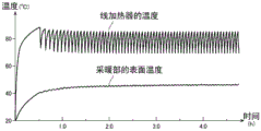
图5是表示向面状采暖工具100供给电源后的线加热器30的温度及采暖部10的表面温度的变化的一例的图。另外,图5所示的线加热器30的温度的上升和下降的周期与图4(c)所示的线加热器30的温度的上升和下降的周期相同,图5是将横轴的时间设定得比图4(c)的横轴的时间长的曲线图。图5所示的横轴的单位是小时[h(hour)]。FIG. 5 is a graph showing an example of changes in the temperature of the wire heater 30 and the surface temperature of the heating unit 10 after power is supplied to the planar heating tool 100 . In addition, the cycle of the rise and fall of the temperature of the wire heater 30 shown in FIG. 5 is the same as the cycle of the rise and fall of the temperature of the wire heater 30 shown in FIG. 4 (c), and FIG. A graph in which time is set longer than the time on the horizontal axis of FIG. 4( c ). The unit of the horizontal axis shown in FIG. 5 is hour [h(hour)].

如图5所示,通过线加热器30的温度反复上升和下降,采暖部10的表面温度也以大致相同的周期反复上升和下降。此时,采暖部10的表面温度也与线加热器30的温度同样,以与由温度设定部21设定的温度水平对应的温度反复上升和下降。另外,采暖部10的表面温度的上限与下限之间的温度范围比线加热器30的温度的上限与下限之间的温度范围小,是使用者注意不到之程度的温度变化。As shown in FIG. 5 , as the temperature of the wire heater 30 repeatedly rises and falls, the surface temperature of the heating unit 10 also repeatedly rises and falls at approximately the same cycle. At this time, the surface temperature of the heating unit 10 repeats rising and falling at a temperature corresponding to the temperature level set by the temperature setting unit 21 similarly to the temperature of the wire heater 30 . In addition, the temperature range between the upper limit and the lower limit of the surface temperature of the heating unit 10 is smaller than the temperature range between the upper limit and the lower limit of the temperature of the wire heater 30, and the temperature change is not noticed by the user.

这样,温度控制部60通过基于由温度检测线34检测到的温度的信息交替地切换对于加热器线32的通电和通电停止,对采暖部10的温度进行控制。In this way, the temperature control unit 60 controls the temperature of the heating unit 10 by alternately switching between energization and de-energization of the heater wire 32 based on the temperature information detected by the temperature detection line 34 .

接着,对检测线加热器30的劣化的方法进行说明。图6是表示通过线加热器30劣化而发生了泄漏电流的状态的图。具体而言,图6(a)是表示交流电源为正半波的情况下的泄漏电流的图,图6(b)是表示交流电源为负半波的情况下的泄漏电流的图。Next, a method of detecting deterioration of the wire heater 30 will be described. FIG. 6 is a diagram showing a state where leakage current has occurred due to deterioration of the wire heater 30 . Specifically, FIG. 6( a ) is a diagram showing leakage current when the AC power supply is a positive half-wave, and FIG. 6( b ) is a diagram showing leakage current when the AC power supply is a negative half-wave.

线加热器30的中间层33周边温度越高则劣化越进展,劣化越进展则绝缘电阻越下降。通过中间层33的绝缘电阻下降,对加热器线32通电的交流电流经由中间层33向温度检测线34泄漏。The higher the temperature around the intermediate layer 33 of the wire heater 30 is, the more the deterioration progresses, and the more the deterioration progresses, the more the insulation resistance decreases. The insulation resistance of the intermediate layer 33 decreases, and the alternating current energized to the heater wire 32 leaks to the temperature detection wire 34 via the intermediate layer 33 .

在如图6(a)所示那样交流电源是正半波的情况下,触点v1为正,触点v2为负。从加热器线32经由中间层33泄漏到温度检测线34的泄漏电流经由触点s1及分支点A流动到平滑电路38,并且经由触点s2流动到控制GND。另外,在交流电源为正半波的情况下,由于二极管D1、D2侧的电压比触点s1、s2高,所以泄漏电流不从触点s1、s2流动到二极管D1、D2侧。通过泄漏电流经由触点s1及分支点A流动到平滑电路38,对由温度检测线34检测的电压加上与泄漏电流对应的电压而向控制部40输入。When the AC power supply is a positive half wave as shown in FIG. 6( a ), the contact v1 is positive and the contact v2 is negative. The leakage current leaked from the heater wire 32 to the temperature detection wire 34 via the intermediate layer 33 flows to the smoothing circuit 38 via the contact s1 and the branch point A, and flows to the control GND via the contact s2 . Also, when the AC power supply is a positive half-wave, since the voltage on the side of diodes D1 and D2 is higher than that of contacts s1 and s2 , leakage current does not flow from contacts s1 and s2 to diodes D1 and D2 . When the leakage current flows into the smoothing circuit 38 via the contact point s1 and the branch point A, a voltage corresponding to the leakage current is added to the voltage detected by the temperature detection line 34 and input to the control unit 40 .

在如图6(b)所示那样交流电源是负半波的情况下,触点v1为负,触点v2为正。从加热器线32经由中间层33泄漏到温度检测线34的泄漏电流经由触点s1及触点s2从二极管D1、D2流动到电阻TF1-R、二极管D3。另外,在交流电源为负半波的情况下,由于分支点A侧的电压比二极管D1、D2侧高,所以泄漏电流不流动到分支点A侧。此外,如果中间层33的劣化进一步进展,则通过加热器线32和温度检测线34被短路而泄漏电流进一步流动到电阻TF1-R中,通过电阻TF1-R发热而成为高温,温度熔断器TF1熔断。通过温度熔断器TF1熔断,即使开关SW是开启,对于加热器线32的通电也被断开,作为最终的保护电路发挥功能。When the AC power supply is a negative half-wave as shown in FIG. 6( b ), the contact v1 is negative and the contact v2 is positive. The leakage current leaking from the heater wire 32 to the temperature detection wire 34 via the intermediate layer 33 flows from the diodes D1 and D2 to the resistor TF1 -R and the diode D3 via the contact s1 and the contact s2 . In addition, when the AC power supply is a negative half-wave, since the voltage on the side of the branch point A is higher than that on the side of the diodes D1 and D2 , leakage current does not flow to the side of the branch point A. In addition, if the deterioration of the intermediate layer 33 progresses further, the heater line 32 and the temperature detection line 34 are short-circuited, and the leakage current further flows into the resistor TF1-R, and the resistor TF1-R generates heat to become high temperature, and the temperature fuse TF1 fuse. When the thermal fuse TF1 is blown, even if the switch SW is turned on, the energization to the heater wire 32 is cut off, and functions as a final protection circuit.

这里,如果着眼于图6(a)及图6(b)所示的分支点A的电压,则在分支点A,仅在交流电源的正半波时发生与泄漏电流对应的电压。另一方面,如果着眼于向图6(a)及图6(b)所示的电路的控制部40输入的电压,则仅在交流电源的正半波时发生的与泄漏电流对应的电压被平滑电路38平滑化。Here, focusing on the voltage at the branch point A shown in FIGS. 6( a ) and 6 ( b ), at the branch point A, a voltage corresponding to the leakage current occurs only in the positive half-wave of the AC power supply. On the other hand, if attention is paid to the voltage input to the control unit 40 of the circuit shown in FIG. 6(a) and FIG. The smoothing circuit 38 smoothes.

图7是表示根据泄漏电流检测的电压的变化的图。这里,假设交流电源为60Hz而进行说明。如图7所示,在泄漏电流较低的情况下,在分支点A处每1/60秒即每个交流的半波发生与泄漏电流对应的电压dv。与该泄漏电流对应的电压dv通过被平滑电路38平滑化而成为电压adv(参照图7所示的“平滑值”)。结果,对于控制部40输入对由温度检测线34检测到的电压加上与泄漏电流对应的电压adv后的电压。FIG. 7 is a graph showing changes in voltage detected by leakage current. Here, the description will be given assuming that the AC power supply is 60 Hz. As shown in FIG. 7 , when the leakage current is low, a voltage dv corresponding to the leakage current occurs at the branch point A every 1/60 second, that is, every half-wave of AC. The voltage dv corresponding to this leakage current is smoothed by the smoothing circuit 38 to become a voltage adv (see "smoothed value" shown in FIG. 7 ). As a result, a voltage obtained by adding a voltage adv corresponding to the leakage current to the voltage detected by the temperature detection line 34 is input to the control unit 40 .

此外,如果泄漏电流增加而变高,则在分支点A,每1/60秒对应于泄漏电流而发生比电压dv高的电压dv+(参照图7所示的虚线)。与该泄漏电流对应的电压dv+被平滑电路38平滑化而成为比电压adv高的电压adv+。结果,对于控制部40输入对由温度检测线34检测到的电压加上与泄漏电流对应的电压adv+后的电压。Also, when the leakage current increases and becomes high, at the branch point A, a voltage dv+ higher than the voltage dv is generated every 1/60 second corresponding to the leakage current (see the dotted line shown in FIG. 7 ). The voltage dv+ corresponding to this leakage current is smoothed by the smoothing circuit 38 to become a voltage adv+ higher than the voltage adv. As a result, the voltage obtained by adding the voltage adv+ corresponding to the leakage current to the voltage detected by the temperature detection line 34 is input to the control unit 40 .

这样,如果对于控制部40输入与泄漏电流对应而加上的电压,则与电流没有泄漏而对控制部40仅输入由温度检测线34检测到的电压的情况相比,温度检测线34的电压的变化等成为不同的动态。具体地参照图8说明与对控制部40输入了对应于泄漏电流而加上的电压的情况下的温度控制部60的动作对应的温度检测线34的电压的变化、对于加热器线32的通电状态的变化、线加热器30的温度的变化。In this way, when a voltage added corresponding to the leakage current is input to the control unit 40, the voltage of the temperature detection line 34 is lower than that of a case where only the voltage detected by the temperature detection line 34 is input to the control unit 40 without current leakage. Changes etc. become different dynamics. Specifically, referring to FIG. 8 , the change in the voltage of the temperature detection line 34 and the energization of the heater line 32 corresponding to the operation of the temperature control unit 60 when a voltage applied corresponding to the leakage current is input to the control unit 40 will be described. Changes in the state, changes in the temperature of the wire heater 30 .

图8(a)是表示温度检测线34的电压的变化的图,将有泄漏电流的情况下的温度检测线34的电压的变化用实线表示,将没有泄漏电流的情况下的温度检测线34的电压的变化用虚线表示。另外,没有泄漏电流的情况下的温度检测线34的电压的变化与图4(a)的实线的变化相同。图8(b)是表示加热器线32的通电状态的变化的图,将有泄漏电流的情况下的通电状态的变化用实线表示,将没有泄漏电流的情况下的通电状态的变化用虚线表示。另外,没有泄漏电流的情况下的通电状态的变化与图4(b)的实线的变化相同。图8(c)是表示线加热器30的温度的变化的图,将有泄漏电流的情况下的线加热器30的温度的变化用实线表示,将没有泄漏电流的情况下的线加热器30的温度的变化用虚线表示。另外,没有泄漏电流的情况下的线加热器30的温度的变化与图4(c)的实线的变化相同。Fig. 8 (a) is a figure showing the change of the voltage of the temperature detection line 34, and the change of the voltage of the temperature detection line 34 under the situation of leakage current is represented by a solid line, and the change of the voltage of the temperature detection line 34 under the situation of no leakage current The variation of the voltage at 34 is indicated by a dotted line. In addition, the change of the voltage of the temperature detection line 34 when there is no leakage current is the same as the change of the solid line of FIG.4(a). FIG. 8( b ) is a diagram showing changes in the energized state of the heater wire 32 . The change in the energized state when there is a leakage current is shown by a solid line, and the change in the energized state when there is no leakage current is shown by a dotted line. express. In addition, the change of the energized state when there is no leakage current is the same as the change of the solid line in FIG. 4( b ). Fig. 8(c) is a diagram showing the change of the temperature of the wire heater 30. The change of the temperature of the wire heater 30 under the condition of leakage current is represented by a solid line, and the change of the temperature of the wire heater 30 under the condition of no leakage current is shown by a solid line. The change in temperature of 30 is indicated by the dashed line. In addition, the change in the temperature of the wire heater 30 when there is no leakage current is the same as the change in the solid line in FIG. 4( c ).

图8(a)所示的电压值Va2是线加热器30的温度上升时的温度检测线34的电压值。电压值Va2相比没有泄漏电流的情况下的电压值Va1被加上了电压Δv(偏移量Δv)。电压Δv相当于图7所示的电压adv或电压adv+。这里,如图8(b)所示那样是对加热器线32通电的状态(开启状态),如图8(c)所示那样线加热器30的温度也继续上升。然后,通过电压值相应于被加上电压Δv而较快地达到上限阈值,继电器RL成为关闭,成为对于加热器线32停止通电的状态(关闭状态)。因而,如图8(b)所示,开启状态的时间HH相应于电压值较快地达到上限阈值而较快地对于加热器线32停止通电,所以相比没有泄漏电流的情况下的开启状态的时间HHs变短。此外,如图8(c)所示,线加热器30的温度由于对于加热器线32较快地停止通电,所以相比没有泄漏电流的情况线加热器30的温度在达到温度Toff之前较快地开始下降。此外,如图8(a)所示,如果电压值达到上限阈值,则通过对加热器线32停止通电,不再有泄漏的电流自身,所以电压Δv量的相加立即消失,回到没有泄漏电流的情况下的温度检测线34的电压值(图8(a)所示的虚线上的电压值),逐渐下降。The voltage value Va2 shown in FIG. 8( a ) is the voltage value of the temperature detection line 34 when the temperature of the wire heater 30 rises. A voltage Δv (offset amount Δv) is added to the voltage value Va2 compared to the voltage value Va1 in the case of no leakage current. The voltage Δv corresponds to the voltage adv or the voltage adv+ shown in FIG. 7 . Here, as shown in FIG. 8( b ), the heater wire 32 is energized (open state), and the temperature of the wire heater 30 continues to rise as shown in FIG. 8( c ). Then, when the voltage value reaches the upper limit threshold quickly in accordance with the applied voltage Δv, the relay RL is turned off, and the heater wire 32 is stopped from being energized (closed state). Therefore, as shown in FIG. 8( b ), the time HH of the on state is corresponding to the voltage value reaching the upper limit threshold sooner, and the heater line 32 is stopped from being energized faster, so compared with the on state without leakage current, The time HHs becomes shorter. In addition, as shown in FIG. 8( c ), since the temperature of the wire heater 30 stops energizing the heater wire 32 quickly, the temperature of the wire heater 30 reaches the temperature Toff faster than in the case of no leakage current. began to descend. In addition, as shown in FIG. 8(a), if the voltage value reaches the upper threshold value, by stopping the energization of the heater wire 32, there is no leakage current itself, so the addition of the voltage Δv amount disappears immediately, returning to no leakage. The voltage value of the temperature detection line 34 (the voltage value on the dotted line shown in FIG. 8( a )) in the case of a current gradually decreases.

图8(a)所示的电压值Vb2是通过停止对于加热器线32的通电而线加热器30的温度下降时的温度检测线34的电压值。这里,继电器RL是关闭,是对于图8(b)所示的加热器线32停止了通电的状态(关闭状态)。因而,如图8(c)所示,线加热器30的温度也继续下降。然后,通过电压值相应于电压Δv量的加上消失而较快地达到下限阈值,继电器RL成为开启,成为对于加热器线32通电的状态(开启状态)。因而,如图8(b)所示,关闭状态的时间HL相应于电压值较快地达到下限阈值而较快地对加热器线32通电,所以相比没有泄漏电流的情况下的关闭状态的时间HLs变短。此外,如图8(c)所示,线加热器30的温度由于对于加热器线32较快地通电,所以相比没有泄漏电流的情况更快地开始上升。The voltage value Vb2 shown in FIG. 8( a ) is the voltage value of the temperature detection line 34 when the temperature of the wire heater 30 drops by stopping the energization to the heater wire 32 . Here, the relay RL is closed, and is a state (closed state) in which energization to the heater wire 32 shown in FIG. 8( b ) is stopped. Therefore, as shown in FIG. 8( c ), the temperature of the wire heater 30 also continues to drop. Then, when the voltage value disappears according to the addition of the voltage Δv and quickly reaches the lower limit threshold value, the relay RL is turned on, and the heater wire 32 is energized (open state). Therefore, as shown in FIG. 8( b ), the time HL of the off state corresponds to the voltage value reaching the lower limit threshold sooner and the heater wire 32 is energized faster, so the time HL of the off state is compared with that in the case of no leakage current. The time HLs become shorter. In addition, as shown in FIG. 8( c ), the temperature of the wire heater 30 starts to rise sooner than in the case of no leakage current due to faster energization of the heater wire 32 .

以后也同样,通过温度检测线34的电压值被加上电压Δv、或电压Δv的加上立即消失等的影响,对于加热器线32通电的开启状态的时间HH和停止通电的关闭状态的时间HL分别相比没有泄漏电流的情况变短,所以对于加热器线32的通电和通电停止的周期变短。此外,线加热器30的温度其上升和下降的周期也变短,并且由于未达到没有泄漏电流的情况下的温度Toff,所以线加热器30的温度(平均温度)下降。In the same way, the voltage value passing through the temperature detection line 34 is affected by the addition of the voltage Δv, or the addition of the voltage Δv disappears immediately, and the time HH of the ON state when the heater wire 32 is energized and the time HH of the OFF state when the energization is stopped. HL is respectively shorter than the case of no leakage current, so the cycle of energization and energization stop to the heater wire 32 is shortened. In addition, the cycle of temperature rise and fall of the wire heater 30 is also shortened, and the temperature (average temperature) of the wire heater 30 falls because the temperature Toff in the case of no leakage current is not reached.

另外,由于泄漏电流越增加则电压Δv越大,所以随着泄漏电流增加,对于加热器线32的通电和通电停止的周期变短。同样,随着泄漏电流增加,线加热器30的温度其上升和下降的周期也变短,线加热器30的温度(平均温度)下降。In addition, since the voltage Δv increases as the leakage current increases, the cycle of energization and stoppage of energization to the heater wire 32 becomes shorter as the leakage current increases. Also, as the leakage current increases, the period during which the temperature of the wire heater 30 rises and falls becomes shorter, and the temperature (average temperature) of the wire heater 30 decreases.

本实施方式的通电控制部50基于通过发生泄漏电流而发生的上述的各种变化,在温度熔断器TF1被熔断之前检测出线加热器30的劣化,对于加热器线32通电停止,继续通电停止。以下,参照流程图对具体的由通电控制部50进行的处理进行说明。The energization control unit 50 of this embodiment detects the deterioration of the wire heater 30 before the thermal fuse TF1 is blown based on the above-mentioned various changes caused by the leakage current, stops energization to the heater wire 32 , and stops continuation of energization. Hereinafter, specific processing performed by the energization control unit 50 will be described with reference to a flowchart.

(第1实施例)(first embodiment)

在第1实施例中,通电控制部50基于关于对于加热器线32的通电及通电停止的信息,具体而言基于对于加热器线32的通电及通电停止的周期,对于加热器线32继续通电停止。In the first embodiment, the energization control unit 50 continues to energize the heater wire 32 based on the information on the energization and cessation of the energization to the heater wire 32 , specifically, based on the cycle of energization and cessation of the heater wire 32 . stop.

图9是表示第1实施例的由通电控制部50进行的处理的一例的流程图。另外,在包括图9的以后的流程图中,通过通电控制部50执行存储在通电控制部50内的存储器中的程序来实现。FIG. 9 is a flowchart showing an example of processing performed by the energization control unit 50 in the first embodiment. In addition, in the following flowcharts including FIG. 9 , it is realized by the energization control unit 50 executing a program stored in a memory in the energization control unit 50 .

在S10中,通电控制部50取得对于加热器线32通电的开启状态的时间HH(参照图8(b))。通电控制部50通过测量继电器切换部66对继电器RL输出开启的信号的时间,取得对于加热器线32通电的开启状态的时间HH。但是,通电控制部50也可以通过测量继电器RL成为开启的时间或开关SW成为开启的时间,来取得开启状态的时间HH。In S10, the energization control part 50 acquires the time HH of the ON state which energized the heater wire 32 (refer FIG.8(b)). The energization control unit 50 acquires the time HH of the ON state when the heater wire 32 is energized by measuring the time when the relay switching unit 66 outputs an ON signal to the relay RL. However, the energization control unit 50 may acquire the ON state time HH by measuring the ON time of the relay RL or the ON time of the switch SW.

在S11中,通电控制部50取得对于加热器线32停止了通电的关闭状态的时间HL(参照图8(b))。通电控制部50通过测量继电器切换部66对继电器RL输出关闭的信号的时间,取得对于加热器线32停止通电的关闭状态的时间HL。但是,通电控制部50也可以通过测量继电器RL成为关闭的时间、或者开关SW成为关闭的时间,来取得关闭状态的时间HL。In S11, the energization control part 50 acquires the time HL of the OFF state in which energization to the heater wire 32 was stopped (refer FIG.8(b)). The energization control unit 50 acquires the off-state time HL when the energization to the heater wire 32 is stopped by measuring the time when the relay switching unit 66 outputs an off signal to the relay RL. However, the energization control unit 50 may acquire the off-state time HL by measuring the time when the relay RL is turned off or the time when the switch SW is turned off.

在S12中,通电控制部50取得通电及通电停止的周期。通电控制部50通过将开启状态的时间HH与关闭状态的时间HL相加来取得通电及通电停止的周期。如上述那样,随着泄漏电流增加,对于加热器线32的通电及通电停止的周期变短。In S12, the energization control unit 50 acquires the cycle of energization and energization stop. The energization control unit 50 acquires the period of energization and energization stop by adding the time HH of the ON state and the time HL of the OFF state. As described above, as the leakage current increases, the cycle of energization and stoppage of energization to the heater wire 32 becomes shorter.

在S13中,通电控制部50计算所取得的通电及通电停止的周期与没有泄漏电流时的通电及通电停止的周期的差。另外,没有泄漏电流时的通电及通电停止的周期相当于图4(b)所示的将开启状态的时间HHs与关闭状态的时间HLs相加的时间,被预先存储在通电控制部50内的存储器中。此外,通电控制部50也可以将S10~S13反复进行多次,计算差的平均值。In S13 , the energization control unit 50 calculates a difference between the acquired energization and energization stop periods and the energization and energization stop periods when there is no leakage current. In addition, the cycle of energization and energization stop when there is no leakage current corresponds to the time of adding the time HHs of the on state and the time HLs of the off state shown in FIG. in memory. In addition, the energization control part 50 may repeat S10-S13 several times, and may calculate the average value of a difference.

在S14中,通电控制部50判定周期的差是否为规定的值(阈值Ta)以上,在是规定的值以上的情况下向S15前进,在不是规定的值以上的情况下向S10返回。规定的值被预先存储在通电控制部50内的存储器中,不论由温度设定部21设定的温度水平如何都为一定。此外,规定的值设定为比温度熔断器TF1被熔断时(之前)的通电及通电停止的周期与没有泄漏电流时的通电及通电停止的周期的差小的值。另外,周期的差也可以是通过将S10~S13反复进行多次而计算的平均值。In S14, the energization control unit 50 determines whether or not the period difference is greater than or equal to a predetermined value (threshold value Ta). If the difference is greater than the predetermined value, it proceeds to S15, and if it is not greater than the predetermined value, it returns to S10. The predetermined value is stored in advance in a memory in the energization control unit 50 , and is constant regardless of the temperature level set by the temperature setting unit 21 . In addition, the predetermined value is set to a value smaller than the difference between the energization and energization stop cycle when the thermal fuse TF1 is blown (before) and the energization cycle and the energization stop cycle when there is no leakage current. In addition, the cycle difference may be an average value calculated by repeating S10 to S13 a plurality of times.

在S15中,通电控制部50判定为线加热器30劣化了,不论由温度检测线34检测的温度的信息如何,都对于加热器线32通电停止,继续通电停止。具体而言,通电控制部50通过经由未图示的安全电路将继电器RL关闭或将开关SW关闭,继续对于加热器线32的通电停止。使由通电控制部50进行的通电停止的处理比由温度控制部60进行的温度控制的处理优先。此外,通电控制部50通过使报告部22点亮的时间及灭掉的时间变化,向使用者报告因为线加热器30的劣化而继续通电停止。In S15 , the energization control unit 50 determines that the wire heater 30 has deteriorated, and stops energization to the heater wire 32 regardless of the temperature information detected by the temperature detection line 34 , and continues to stop energization. Specifically, the energization control unit 50 continues to stop the energization of the heater wire 32 by turning off the relay RL or the switch SW via a safety circuit not shown. The process of stopping energization by the energization control unit 50 takes priority over the process of temperature control by the temperature control unit 60 . In addition, the energization control unit 50 notifies the user that the continuation of energization is stopped due to the deterioration of the wire heater 30 by changing the time when the reporting unit 22 is turned on and the time when it is turned off.

这样,根据本实施例,能够基于通电及通电停止的周期,通过继续对于加热器线32的通电停止而在温度熔断器TF1被熔断之前较早地检测到线加热器30的劣化。另外,由于通电及通电停止的周期其时间比交流电源的波形的周期长,所以不需要高精度地测量周期,所以能够以低成本检测线加热器30的劣化。Thus, according to the present embodiment, it is possible to detect deterioration of the wire heater 30 early before the thermal fuse TF1 is blown by continuing to stop the energization of the heater wire 32 based on the cycle of energization and energization stop. In addition, since the cycle of energization and energization stop is longer than the cycle of the waveform of the AC power supply, it is not necessary to measure the cycle with high accuracy, and thus the deterioration of the wire heater 30 can be detected at low cost.

另外,在第1实施例中,对使用通电及通电停止的周期的情况进行了说明,但也可以在对加热器线32通电的开启状态的时间HH与没有泄漏电流的情况下的开启状态的时间HHs的差是规定的值(阈值Tb)以上的情况下对加热器线32继续通电停止。此外,在不对加热器线32通电的关闭状态的时间HL与没有泄漏电流的情况下的关闭状态的时间HLs的差是规定的值(阈值Tc)以上的情况下,也可以对加热器线32继续通电停止。In addition, in the first embodiment, the case of using the cycle of energization and energization stop was described, but the time HH of the ON state when the heater wire 32 is energized and the ON state when there is no leakage current may be used. When the difference in time HHs is equal to or greater than a predetermined value (threshold value Tb), the continuation of energization to the heater wire 32 is stopped. In addition, when the difference between the off-state time HL when the heater wire 32 is not energized and the off-state time HLs when there is no leakage current is greater than or equal to a predetermined value (threshold value Tc), the heater wire 32 may be Continue to power off.

此外,也可以将对加热器线32通电的开启状态的时间HH与规定的时间(阈值Td)比较,在规定的时间以下的情况下对加热器线32继续通电停止。此外,也可以将对加热器线32不通电的关闭状态的时间HL与规定的时间(阈值Te)比较,在规定的时间以下的情况下对加热器线32继续通电停止。此外,也可以将所测量的通电及通电停止的周期与规定的周期(阈值Tf)比较,在规定的周期以下的情况下对加热器线32继续通电停止。In addition, the ON state time HH in which the heater wire 32 is energized may be compared with a predetermined time (threshold value Td), and the energization to the heater wire 32 may be stopped when the predetermined time is less than the predetermined time. In addition, the off-state time HL in which the heater wire 32 is not energized may be compared with a predetermined time (threshold Te), and the energization of the heater wire 32 may be stopped if the predetermined time is less than the predetermined time. In addition, the measured cycle of energization and energization stop may be compared with a predetermined cycle (threshold value Tf), and when the cycle is equal to or less than the predetermined cycle, energization and stop of heater wire 32 may be continued.

(第2实施例)(second embodiment)

在第2实施例中,通电控制部50基于关于对于加热器线32的通电及通电停止的信息,具体而言对于加热器线32的通电及通电停止的次数,继续对于加热器线32的通电停止。图10是表示由第2实施例的通电控制部50进行的处理的一例的流程图。In the second embodiment, the energization control unit 50 continues the energization of the heater wire 32 based on the information on the energization and energization stop of the heater wire 32 , specifically, the number of energization and energization stops of the heater wire 32 stop. FIG. 10 is a flowchart showing an example of processing performed by the energization control unit 50 of the second embodiment.

在S20中,通电控制部50将对于加热器线32通电及通电停止的次数计数,加到第1计数器中。通电控制部50在被通电时对第1计数器加“1”,接着在通电停止时对第1计数器加“1”。通电控制部50通过将继电器RL成为开启及关闭的次数计数,或将开关SW成为开启及关闭的次数计数,计数被通电及通电停止的次数。由于如上述那样随着泄漏电流增加而对于加热器线32的通电及通电停止的周期变短,所以随着泄漏电流增加,在一定时间的期间中被通电及通电停止的次数变大。In S20 , the energization control unit 50 counts the number of times of energization and stop of energization to the heater wire 32 , and adds it to the first counter. The energization control unit 50 adds "1" to the first counter when the energization is applied, and then adds "1" to the first counter when the energization is stopped. The energization control unit 50 counts the number of times the relay RL is turned on and off, or the number of times the switch SW is turned on and off, thereby counting the number of times energized and stopped. As the leak current increases, the period of energization and stop of energization to the heater wire 32 becomes shorter as described above. Therefore, as the leak current increases, the number of times of energization and stop of energization within a certain period of time increases.

在S21中,通电控制部50判定在一定时间的期间中计数的次数(第1计数器)是否成为了规定的次数(阈值N,例如10次)以上。在规定的次数以上的情况下,对第2计数器加“1”,向S22前进。另一方面,在不为规定的次数以上的情况下向S20返回,继续被通电及通电停止的次数的计数。阈值N被预先存储在通电控制部50内的存储器中,不论由温度设定部21设定的温度水平如何都为一定。此外,阈值N设定为比温度熔断器被熔断时的对于加热器线32通电及通电停止的次数小的次数。In S21 , the energization control unit 50 determines whether or not the number of times counted (the first counter) during a certain period of time has become more than or equal to a predetermined number of times (threshold value N, for example, 10 times). If it is more than the predetermined number of times, "1" is added to the second counter, and the process proceeds to S22. On the other hand, if it is not more than the predetermined number of times, it returns to S20, and the count of the number of times of energization and energization stop is continued. The threshold value N is stored in advance in a memory in the energization control unit 50 , and is constant regardless of the temperature level set by the temperature setting unit 21 . In addition, the threshold value N is set to a number smaller than the number of times that the heater wire 32 is energized and energized when the thermal fuse is blown.

在S22中,通电控制部50判定在一定时间的期间中计数的次数(第1计数器)为规定的次数以上的情况是否连续了规定的次数(阈值M,例如3次)。即,判定是否将第2计数器连续地相加而达到了规定的次数(阈值M,例如3次)。在连续了规定的次数的情况下向S23前进。另一方面,在没有连续规定的次数的情况下向S20返回,在将所计数的次数(第1计数器、第2计数器)复位后,继续被通电及通电停止的次数的计数。In S22 , the energization control unit 50 determines whether or not the counted number of times (first counter) is equal to or greater than a predetermined number of times (threshold value M, for example, 3 times) continuously for a certain period of time. That is, it is determined whether the second counter is continuously added up to a predetermined number of times (threshold value M, for example, 3 times). When the predetermined number of times has been continued, the process proceeds to S23. On the other hand, if there is no continuous predetermined number of times, return to S20, after resetting the counted number of times (first counter, second counter), counting of the number of times of energization and energization stop is continued.

在S23中,通电控制部50判定为线加热器30劣化了,不论由温度检测线34检测到的温度的信息如何,都对于加热器线32通电停止,继续通电停止。该处理是与上述的S15同样的处理。In S23 , the energization control unit 50 determines that the wire heater 30 is degraded, and stops energization to the heater wire 32 regardless of the temperature information detected by the temperature detection wire 34 , and continues to stop energization. This processing is the same processing as S15 described above.

这样,根据本实施例,通过基于通电及通电停止的次数继续对于加热器线32的通电停止,能够在温度熔断器TF1被熔断之前较早地检测出线加热器30的劣化。Thus, according to the present embodiment, by continuing to stop the energization of the heater wire 32 based on the number of times of energization and energization stop, deterioration of the wire heater 30 can be detected early before the thermal fuse TF1 is blown.

另外,在第2实施例中,对将被通电及通电停止的次数计数的情况进行了说明,但也可以仅计数被通电的次数,判定是否在一定时间的期间中所计数的次数成为了规定的次数(阈值N/2,例如5次)以上,也可以仅计数被通电停止的次数,判定一定时间的期间中计数的次数是否成为了规定的次数(阈值N/2,例如5次)以上。此外,也可以在经过一定时间之前所计数的次数就达到了规定的次数的情况下,也可以不等待经过一定时间而将所计数的次数复位,开始下个一定时间的计时后,计数被通电及通电停止的次数。这样,通过不是等待经过一定时间而开始下个一定时间的计时,能够更早地检测出线加热器30的劣化。In addition, in the second embodiment, the case of counting the number of energized and energized stops has been described, but it is also possible to count only the number of energized times and determine whether or not the counted number of times has reached the specified number of times during a certain period of time. (threshold value N/2, such as 5 times) or more, it is also possible to only count the number of times the power is stopped, and determine whether the number of times counted during a certain period of time has become more than a predetermined number of times (threshold value N/2, such as 5 times) . In addition, when the counted number of times reaches the predetermined number of times before a certain time has elapsed, the counted number of times may be reset without waiting for a certain time to elapse, and the counting may be powered on after the next certain time counting is started. and the number of power-off times. In this way, the deterioration of the wire heater 30 can be detected earlier by starting the counting of the next predetermined time without waiting for the elapse of the predetermined time.

(第3实施例)(third embodiment)

在第3实施例中,通电控制部50基于关于线加热器30的温度的信息,具体而言基于线加热器30的平均温度,继续对于加热器线32的通电停止。In the third embodiment, the energization control unit 50 continues to stop the energization of the heater wire 32 based on the information on the temperature of the wire heater 30 , specifically, based on the average temperature of the wire heater 30 .

图11是表示由第3实施例的通电控制部50进行的处理的一例的流程图。在第3实施例中,面状采暖工具100具有测量线加热器30的温度的温度传感器。温度传感器优选的是能够在线加热器30的多个点测量,例如可以使用与线加热器30分体地粘贴在线加热器30上的膜状的多点传感器。由温度传感器测量的温度的信息被向通电控制部50输入。FIG. 11 is a flowchart showing an example of processing performed by the energization control unit 50 of the third embodiment. In the third embodiment, the surface heating tool 100 has a temperature sensor for measuring the temperature of the wire heater 30 . The temperature sensor is preferably capable of measuring multiple points of the line heater 30 , and for example, a film-shaped multi-point sensor attached to the line heater 30 separately from the line heater 30 may be used. Information on the temperature measured by the temperature sensor is input to the energization control unit 50 .

在S30中,通电控制部50从温度传感器持续一定时间而总是取得线加热器30的多点的温度的信息。通电控制部50将所取得的线加热器30的温度的信息存储。In S30, the energization control part 50 always acquires the temperature information of the multiple points of the wire heater 30 from a temperature sensor for a predetermined period of time. The energization control unit 50 stores the acquired temperature information of the wire heater 30 .

在S31中,通电控制部50根据所取得的多点的温度的信息计算线加热器30的平均温度。如上述那样,随着泄漏电流增加而线加热器30的平均温度下降。In S31, the energization control part 50 calculates the average temperature of the wire heater 30 from the acquired temperature information of multiple points. As described above, the average temperature of the wire heater 30 decreases as the leakage current increases.

在S32中,通电控制部50计算所计算出的线加热器30的平均温度与没有泄漏电流时的线加热器30的平均温度的差。另外,没有泄漏电流时的线加热器30的平均温度是与由温度设定部21设定的温度水平对应的温度,被预先存储在通电控制部50内的存储器中。此外,通电控制部50也可以将S30~S32反复进行多次,计算差的平均值。In S32 , the energization control unit 50 calculates the difference between the calculated average temperature of the wire heater 30 and the average temperature of the wire heater 30 when there is no leakage current. In addition, the average temperature of the wire heater 30 when there is no leakage current is a temperature corresponding to the temperature level set by the temperature setting unit 21 , and is stored in a memory in the energization control unit 50 in advance. In addition, the energization control part 50 may repeat S30-S32 several times, and may calculate the average value of a difference.

在S33中,通电控制部50判定温度的差是否为规定的值(阈值Tg)以上,在为规定的值以上的情况下向S33前进,在不为规定的值以上的情况下向S30返回。规定的值被预先存储在通电控制部50内的存储器中,不论由温度设定部21设定的温度水平如何都为一定。此外,规定的值被设定为比温度熔断器TF1被熔断时的线加热器30的平均温度与没有泄漏电流时的线加热器30的平均温度的差小的值。另外,温度的差也可以是通过将S30~S32反复进行多次而计算出的平均值。In S33 , the energization control unit 50 determines whether the temperature difference is greater than or equal to a predetermined value (threshold value Tg). The predetermined value is stored in advance in a memory in the energization control unit 50 , and is constant regardless of the temperature level set by the temperature setting unit 21 . In addition, the predetermined value is set to a value smaller than the difference between the average temperature of the wire heater 30 when the thermal fuse TF1 is blown and the average temperature of the wire heater 30 when there is no leakage current. In addition, the temperature difference may be an average value calculated by repeating S30 to S32 a plurality of times.

在S34中,通电控制部50判定为线加热器30劣化了,不论由温度检测线34检测的温度的信息如何,都对加热器线32通电停止,继续通电停止。该处理是与上述的S15同样的处理。In S34 , the energization control unit 50 determines that the wire heater 30 is degraded, and stops energizing the heater wire 32 regardless of the information of the temperature detected by the temperature detection wire 34 , and continues to stop energizing. This processing is the same processing as S15 described above.

这样,根据本实施例,通过基于线加热器30的温度继续对于加热器线32的通电停止,能够在温度熔断器TF1被熔断之前较早地检测出线加热器30的劣化。Thus, according to the present embodiment, by continuing to stop the energization of the heater wire 32 based on the temperature of the wire heater 30 , deterioration of the wire heater 30 can be detected early before the thermal fuse TF1 is blown.

另外,在第3实施例中,对持续一定时间经常性地取得线加热器30的多点的温度的信息来计算平均温度的情况进行了说明,但也可以将在线加热器30的多点处温度从上升切换为下降时的温度(上限温度)、从下降切换为上升时的温度(下限温度)存储,根据多点处的上限温度和下限温度来计算平均温度。In addition, in the third embodiment, the case where the temperature information of multiple points of the line heater 30 is frequently acquired for a certain period of time to calculate the average temperature has been described, but it is also possible to use the temperature information of multiple points of the line heater 30 The temperature when the temperature switches from rising to falling (upper limit temperature), and the temperature when switching from falling to rising (lower limit temperature) are stored, and the average temperature is calculated from the upper limit temperature and lower limit temperature at multiple points.

此外,也可以持续一定时间仅根据多点的上限温度计算平均值而计算上限平均温度,计算与没有泄漏电流时的线加热器30的上限平均温度的差,判定是否是规定值(阈值Th)以上。Alternatively, the upper limit average temperature may be calculated only by calculating the average value based on the upper limit temperature at multiple points for a certain period of time, and the difference from the upper limit average temperature of the wire heater 30 when there is no leakage current may be calculated to determine whether it is a predetermined value (threshold value Th). above.

此外,也可以将线加热器30的多点处的平均温度与规定的温度(阈值Ti)比较,在规定的温度以上的情况下对于加热器线32继续通电停止。此外,也可以将线加热器30的多点处的上限平均温度与规定的温度(阈值Tj)比较,在规定的温度以上的情况下对于加热器线32继续通电停止。Alternatively, the average temperature at multiple points of the wire heater 30 may be compared with a predetermined temperature (threshold Ti), and if the temperature exceeds the predetermined temperature, continuation of energization to the heater wire 32 may be stopped. Alternatively, the upper limit average temperature at multiple points of the wire heater 30 may be compared with a predetermined temperature (threshold Tj), and if the temperature exceeds the predetermined temperature, continuation of energization to the heater wire 32 may be stopped.

此外,也可以将第1实施例的通电和通电停止的周期替换为线加热器30的温度从上升切换为下降时的周期,或将对第1实施例的加热器线32通电的开启状态的时间HH替换为线加热器30的温度上升的时间,或将不对第1实施例的加热器线32通电的关闭状态的时间HL替换为线加热器30的温度下降的时间等,来检测线加热器30的劣化。In addition, the cycle of energization and energization stop in the first embodiment may be replaced with the cycle when the temperature of the wire heater 30 is switched from rising to falling, or the cycle of the on state of energizing the heater wire 32 in the first embodiment may be replaced. The time HH is replaced by the time when the temperature of the wire heater 30 rises, or the time HL in the off state when the heater wire 32 of the first embodiment is not energized is replaced by the time when the temperature of the wire heater 30 falls, etc., to detect wire heating. Deterioration of device 30.

(第4实施例)(fourth embodiment)

在第4实施例中,通电控制部50基于对于由温度检测线34检测的电压对应于泄漏电流而加上的电压的信息,继续对于加热器线32的通电停止。In the fourth embodiment, the energization control unit 50 continues to stop energization to the heater wire 32 based on the information of the voltage to be applied corresponding to the leakage current to the voltage detected by the temperature detection wire 34 .

图12是表示第4实施例的面状采暖工具100的内部结构的一例的图。Fig. 12 is a diagram showing an example of the internal structure of a planar heating tool 100 according to the fourth embodiment.

这里,对于面状采暖工具100追加了通电控制部50的框图。Here, the block diagram of the energization control unit 50 is added to the planar heating tool 100 .

通电控制部50具有半波整流&过零点检测部121、采样脉冲生成部122、电压检测部123、减法器124、比较器125和平滑电路38。The energization control unit 50 has a half-wave rectification & zero-cross detection unit 121 , a sampling pulse generation unit 122 , a voltage detection unit 123 , a subtractor 124 , a comparator 125 , and a smoothing circuit 38 .

半波整流&过零点检测部121检测即使是有泄漏电流的情况但没有发生与泄漏电流对应的电压的交流电源的负半波的定时。采样脉冲生成部122基于由半波整流&过零点检测部121检测到的负半波的定时生成采样脉冲。The half-wave rectification & zero-cross detection unit 121 detects the timing of the negative half-wave of the AC power supply in which a voltage corresponding to the leakage current is not generated even if there is a leakage current. The sampling pulse generator 122 generates a sampling pulse based on the timing of the negative half wave detected by the half-wave rectification & zero-cross detection unit 121 .

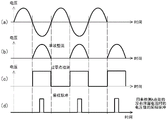
图13是用来说明由半波整流&过零点检测部121及采样脉冲生成部122进行的处理的图。FIG. 13 is a diagram for explaining processing performed by the half-wave rectification & zero-cross detection unit 121 and the sampling pulse generation unit 122 .

图13(a)是表示向半波整流&过零点检测部121输入的交流电源的波形的图。半波整流&过零点检测部121基于被输入的交流电源中的波形将负半波整流。FIG. 13( a ) is a diagram showing a waveform of an AC power input to the half-wave rectification & zero-cross detection unit 121 . The half-wave rectification & zero-cross detection unit 121 rectifies the negative half-wave based on the waveform of the input AC power supply.

图13(b)是表示将负半波整流后的波形的图。半波整流&过零点检测部121基于整流后的波形,检测电压值与0[v]交叉(过零点)的定时。Fig. 13(b) is a diagram showing a waveform after rectifying the negative half-wave. The half-wave rectification & zero-cross detection unit 121 detects the timing at which the voltage value crosses 0 [v] (zero-cross) based on the rectified waveform.

图13(c)是表示检测电压值与0[v]交叉(过零点)的定时后的波形的图。采样脉冲生成部122从发生电压的定时起每规定的时间生成采样脉冲。FIG. 13( c ) is a diagram showing a waveform after the timing at which the voltage value crosses 0 [v] (zero crossing point) is detected. The sampling pulse generator 122 generates a sampling pulse every predetermined time from the timing of generating the voltage.

图13(d)是表示生成采样脉冲的定时的图。采样脉冲生成部122将所生成的采样脉冲向电压检测部123输出。FIG. 13( d ) is a diagram showing the timing at which sampling pulses are generated. The sampling pulse generation unit 122 outputs the generated sampling pulse to the voltage detection unit 123 .

电压检测部123被输入分支点A处的被平滑化之前的温度检测线34的电压值。电压检测部123在从采样脉冲生成部122输出的采样脉冲的定时测量温度检测线34的电压值。因而,电压检测部123尽管是有泄漏电流的情况也能够测量没有泄漏电流时的温度检测线34的电压值Vso。The voltage value of the temperature detection line 34 at the branch point A before being smoothed is input to the voltage detection unit 123 . The voltage detection unit 123 measures the voltage value of the temperature detection line 34 at the timing of the sampling pulse output from the sampling pulse generation unit 122 . Therefore, the voltage detection unit 123 can measure the voltage value Vso of the temperature detection line 34 when there is no leakage current even if there is a leakage current.

平滑电路38将分支点A处的温度检测线34的电压值平滑化。因而,平滑电路38在有泄漏电流的情况下,输出对应于泄漏电流而加上后的电压值(Vso+ΔV)。另外,平滑电路38在没有泄漏电流的情况下,输出温度检测线34的电压值Vso。The smoothing circuit 38 smoothes the voltage value of the temperature detection line 34 at the branch point A. Therefore, when there is a leakage current, the smoothing circuit 38 outputs the voltage value (Vso+ΔV) added corresponding to the leakage current. In addition, the smoothing circuit 38 outputs the voltage value Vso of the temperature detection line 34 when there is no leakage current.

减法器124从由平滑电路38输出的电压值减去由电压检测部123测量的电压值,将减法得到的值向比较器125输出。例如在有泄漏电流的情况下,减法器124从由平滑电路38输出的对应于泄漏电流而加上后的电压值(Vso+ΔV),减去由电压检测部123测量的电压值Vso,将电压值ΔV向比较器125输出。The subtracter 124 subtracts the voltage value measured by the voltage detection unit 123 from the voltage value output by the smoothing circuit 38 , and outputs the subtracted value to the comparator 125 . For example, when there is a leakage current, the subtracter 124 subtracts the voltage value Vso measured by the voltage detection unit 123 from the voltage value (Vso+ΔV) output from the smoothing circuit 38 and added corresponding to the leakage current to obtain The voltage value ΔV is output to the comparator 125 .

比较器125将从减法器124输出的电压值与规定的阈值比较,在电压值为规定的阈值以上的情况下,对于加热器线32通电停止,继续通电停止。The comparator 125 compares the voltage value output from the subtractor 124 with a predetermined threshold value, and when the voltage value is equal to or greater than the predetermined threshold value, energization to the heater wire 32 is stopped, and continuation energization is stopped.

图14是表示第4实施例的由通电控制部50进行的处理的一例的流程图。FIG. 14 is a flowchart showing an example of processing performed by the energization control unit 50 in the fourth embodiment.

在S40中,通电控制部50在对于加热器线32通电的时间中,取得由平滑电路38平滑化之后的温度检测线34的电压值。具体而言,通电控制部50能够取得通过测量向控制部40输入的电压值而被平滑化之后的温度检测线34的电压值。如上述那样,随着泄漏电流增加,温度检测线34的电压值变大。In S40 , the energization control unit 50 obtains the voltage value of the temperature detection line 34 smoothed by the smoothing circuit 38 while the heater wire 32 is energized. Specifically, the energization control unit 50 can obtain the smoothed voltage value of the temperature detection line 34 by measuring the voltage value input to the control unit 40 . As described above, as the leakage current increases, the voltage value of the temperature detection line 34 increases.

在S41中,通电控制部50计算所取得的温度检测线34的电压值与没有泄漏电流时的温度检测线34的电压值的差。这里,没有泄漏电流时的温度检测线34的电压值可以如上述那样,通过电压检测部123在由采样脉冲生成部122生成的采样脉冲的定时测量温度检测线34的电压值来取得。另外,没有泄漏电流时的温度检测线34的电压值也可以预先用与由温度设定部21设定的温度水平对应的值存储在通电控制部50内的存储器中。此外,通电控制部50也可以将S40~S41反复进行多次,计算差的平均值。In S41 , the energization control unit 50 calculates the difference between the acquired voltage value of the temperature detection line 34 and the voltage value of the temperature detection line 34 when there is no leakage current. Here, the voltage value of the temperature detection line 34 when there is no leakage current can be obtained by the voltage detection unit 123 measuring the voltage value of the temperature detection line 34 at the timing of the sampling pulse generated by the sampling pulse generation unit 122 as described above. In addition, the voltage value of the temperature detection line 34 when there is no leakage current may be previously stored in the memory in the energization control unit 50 as a value corresponding to the temperature level set by the temperature setting unit 21 . In addition, the energization control part 50 may repeat S40-S41 several times, and may calculate the average value of a difference.

在S42中,通电控制部50判定电压值的差是否为规定的值(阈值Vc)以上,在为规定的值以上的情况下向S43前进,在不为规定的值以上的情况下向S40返回。规定的值被预先存储在通电控制部50内的存储器中,不论由温度设定部21设定的温度水平如何都为一定。此外,规定的值设定为比温度熔断器被熔断时的电压值与没有泄漏电流时的电压值的差小的值。另外,电压值的差也可以是将S40~S41反复进行多次而计算出的平均值。In S42, the energization control unit 50 determines whether or not the difference in voltage value is equal to or greater than a predetermined value (threshold value Vc). If the difference is equal to or greater than the predetermined value, the process proceeds to S43, and if it is not greater than the predetermined value, the process returns to S40. . The predetermined value is stored in advance in a memory in the energization control unit 50 , and is constant regardless of the temperature level set by the temperature setting unit 21 . In addition, the predetermined value is set to a value smaller than the difference between the voltage value when the thermal fuse is blown and the voltage value when there is no leakage current. In addition, the difference in voltage values may be an average value calculated by repeating S40 to S41 a plurality of times.

在S43中,通电控制部50判定为线加热器30劣化了,对加热器线32通电停止,继续通电停止。该处理是与上述的S15同样的处理。In S43 , the energization control unit 50 determines that the wire heater 30 has deteriorated, stops energization to the heater wire 32 , and stops continuation of energization. This processing is the same processing as S15 described above.

这样,根据本实施例,能够基于由平滑电路38平滑化后的温度检测线34的温度的信息,通过继续对于加热器线32的通电停止,在温度熔断器TF1被熔断之前尽早地检测出线加热器30的劣化。Thus, according to the present embodiment, by continuing to stop the energization of the heater wire 32 based on the information on the temperature of the temperature detection wire 34 smoothed by the smoothing circuit 38, wire heating can be detected as early as possible before the thermal fuse TF1 is blown. Deterioration of device 30.

另外,在第4实施例中,对计算被平滑化的温度检测线34的电压值与没有泄漏电流时的温度检测线34的电压值的差的情况进行了说明,但也可以将在对于加热器线32通电的时间中平滑化的温度检测线34的电压值与规定的电压值(阈值Vd)比较,在为规定的电压值以上的情况下对于加热器线32继续通电停止。In the fourth embodiment, the case of calculating the difference between the smoothed voltage value of the temperature detection line 34 and the voltage value of the temperature detection line 34 when there is no leakage current is described. The smoothed voltage value of the temperature detection line 34 during the energization time of the heater line 32 is compared with a predetermined voltage value (threshold value Vd), and the energization of the heater line 32 is continued and stopped when the predetermined voltage value is greater than or equal to the predetermined voltage value.

(第5实施例)(fifth embodiment)

在第5实施例中,通电控制部50基于对由温度检测线34检测的电压对应于泄漏电流而加上的电压的信息,继续对于加热器线32的通电停止。In the fifth embodiment, the energization control unit 50 continues to stop the energization of the heater wire 32 based on the information of the voltage detected by the temperature detection wire 34 corresponding to the leakage current.

图15是表示第5实施例的面状采暖工具100的内部结构的一例的图。Fig. 15 is a diagram showing an example of the internal structure of a planar heating tool 100 according to the fifth embodiment.

这里,对于面状采暖工具100追加了通电控制部50的框图。另外,与图12同样的结构赋予相同的标号而省略说明。通电控制部50位于分支点A与平滑电路38之间。Here, the block diagram of the energization control unit 50 is added to the planar heating tool 100 . In addition, the same structure as FIG. 12 is given the same code|symbol, and description is abbreviate|omitted. The energization control unit 50 is located between the branch point A and the smoothing circuit 38 .

通电控制部50具有延迟部126。对于延迟部126输入分支点A处的被平滑化前的温度检测线34的电压值。延迟部126测量在被输入的电压值中的交流电源的每个半波输出的峰值电压值,使减法器124将所测量的峰值电压值延迟而输出。这样延迟是为了与由电压检测部123测量温度检测线34的电压值的定时匹配。此外,延迟部126包括峰值电压值而将测量到的电压值依次向平滑电路38输出。The energization control unit 50 has a delay unit 126 . The voltage value of the temperature detection line 34 at the branch point A before being smoothed is input to the delay unit 126 . The delay unit 126 measures the peak voltage value of each half-wave output of the AC power supply among the input voltage values, and causes the subtracter 124 to delay the measured peak voltage value and output it. This delay is to match the timing at which the voltage value of the temperature detection line 34 is measured by the voltage detection unit 123 . Furthermore, the delay unit 126 sequentially outputs the measured voltage values including the peak voltage value to the smoothing circuit 38 .

减法器124从由延迟部126输出的电压值减去由电压检测部123测量的电压值,将减法得到的值向比较器125输出。比较器125将从减法器124输出的电压值与规定的阈值比较,在电压值比规定的阈值大的情况下对于加热器线32通电停止,并继续通电停止。The subtracter 124 subtracts the voltage value measured by the voltage detection unit 123 from the voltage value output by the delay unit 126 , and outputs the subtracted value to the comparator 125 . The comparator 125 compares the voltage value output from the subtractor 124 with a predetermined threshold, and when the voltage value is greater than the predetermined threshold, the energization to the heater wire 32 is stopped, and the continuation of the energization is stopped.

图16是表示由第5实施例的通电控制部50进行的处理的一例的流程图。FIG. 16 is a flowchart showing an example of processing performed by the energization control unit 50 of the fifth embodiment.

在S50中,通电控制部50在对于加热器线32通电的时间中,取得被平滑电路38平滑化前的温度检测线34的峰值电压值。具体而言,通电控制部50通过测量图3所示的分支点A处的电压值,能够取得被平滑化前的温度检测线34的电压值。如上述那样,如果有泄漏电流,则在每个交流的半波对应于泄漏的电流而产生电压。In S50 , the energization control unit 50 acquires the peak voltage value of the temperature detection line 34 before being smoothed by the smoothing circuit 38 while the heater wire 32 is energized. Specifically, the energization control unit 50 can acquire the voltage value of the temperature detection line 34 before being smoothed by measuring the voltage value at the branch point A shown in FIG. 3 . As described above, if there is a leakage current, a voltage is generated corresponding to the leakage current for every alternating half-wave.

在S51中,通电控制部50计算所取得的温度检测线34的峰值电压值与没有泄漏电流时的温度检测线34的电压值的差。这里,没有泄漏电流时的温度检测线34的电压值可以通过电压检测部123在由采样脉冲生成部122生成的采样脉冲的定时测量温度检测线34的电压值来取得。另外,没有泄漏电流时的温度检测线34的电压值也可以预先以与由温度设定部21设定的温度水平对应的值存储在通电控制部50内的存储器。In S51 , the energization control unit 50 calculates the difference between the acquired peak voltage value of the temperature detection line 34 and the voltage value of the temperature detection line 34 when there is no leakage current. Here, the voltage value of the temperature detection line 34 when there is no leakage current can be obtained by the voltage detection unit 123 measuring the voltage value of the temperature detection line 34 at the timing of the sampling pulse generated by the sampling pulse generation unit 122 . In addition, the voltage value of the temperature detection line 34 when there is no leakage current may be stored in memory in the energization control unit 50 in advance as a value corresponding to the temperature level set by the temperature setting unit 21 .

在S52中,通电控制部50判定电压值的差是否为规定的值(阈值Ve)以上,在为规定的值以上的情况下向S53前进,在不为规定的值以上的情况下向S50返回。规定的值被预先存储在通电控制部50内的存储器中,不论由温度设定部21设定的温度水平如何都为一定。此外,规定的值设定为比温度熔断器被熔断时的电压值与没有泄漏电流时的电压值的差小的值。In S52, the energization control unit 50 determines whether or not the difference in voltage value is greater than or equal to a predetermined value (threshold Ve), and if the difference is greater than or equal to the predetermined value, proceeds to S53, and if not greater than the predetermined value, returns to S50. . The predetermined value is stored in advance in a memory in the energization control unit 50 , and is constant regardless of the temperature level set by the temperature setting unit 21 . In addition, the predetermined value is set to a value smaller than the difference between the voltage value when the thermal fuse is blown and the voltage value when there is no leakage current.

在S53中,通电控制部50判定为线加热器30劣化了,对于加热器线32通电停止,并继续通电停止。该处理是与上述的S15同样的处理。In S53 , the energization control unit 50 determines that the wire heater 30 has deteriorated, stops the energization to the heater wire 32 , and continues to stop the energization. This processing is the same processing as S15 described above.

这样,根据本实施例,能够基于由平滑电路38平滑化前的温度检测线34的温度的信息,通过继续对于加热器线32的通电停止,在温度熔断器TF1被熔断之前较早地检测出线加热器30的劣化。Thus, according to the present embodiment, based on information on the temperature of the temperature detection wire 34 before being smoothed by the smoothing circuit 38, by continuing to stop the energization of the heater wire 32, the wire can be detected earlier before the thermal fuse TF1 is blown. Deterioration of the heater 30 .

另外,在第5实施例中,对计算被平滑化前的温度检测线34的峰值电压值与没有泄漏的电流时的温度检测线34的电压值的差的情况进行了说明,但也可以将被平滑化前的温度检测线34的峰值电压值与规定的电压值(阈值Vf)比较,在为规定的电压值以上的情况下对于加热器线32继续通电停止。In addition, in the fifth embodiment, the case of calculating the difference between the peak voltage value of the temperature detection line 34 before being smoothed and the voltage value of the temperature detection line 34 when there is no leakage current has been described, but the The peak voltage value of the temperature detection line 34 before being smoothed is compared with a predetermined voltage value (threshold value Vf), and when the predetermined voltage value is greater than or equal to the predetermined voltage value, energization to the heater line 32 is continuously stopped.

以上,使用上述的实施方式及各实施例说明了本发明,但本发明并不仅限定于上述的实施方式及各实施例,能够在本发明的范围内变更等,也可以将各实施例及变形例适当组合。As mentioned above, the present invention has been described using the above-mentioned embodiment and each example, but the present invention is not limited to the above-mentioned embodiment and each example, and changes and the like can be made within the scope of the present invention. An appropriate combination of examples.

在上述的实施方式中,对面状采暖工具是电热毯的情况进行了说明,但并不限于该情况,也可以对电热垫、电热毛毯等应用。此外,并不限于交流100V的制品,对于交流200V的制品也能够应用。In the above-mentioned embodiment, the case where the planar heating tool is an electric blanket has been described, but it is not limited to this case, and it can also be applied to an electric heating pad, an electric heating blanket, and the like. In addition, it is not limited to the product of AC 100V, and it can apply also to the product of AC 200V.

Claims (10)

1. A planar heating tool comprises:
a wire heater wired in the heating section and having a heater wire, a temperature detection wire, and an intermediate layer located between the heater wire and the temperature detection wire; and
a control means for controlling the temperature of the heating section by alternately switching between energization and interruption of the heater wire based on information of the temperature detected by the temperature detection wire,
it is characterized in that the preparation method is characterized in that,
the control means continues the stop of the energization of the heater wire based on information on at least one of the energization and the stop of the energization of the heater wire.
2. Planar heating tool according to claim 1,
the information on at least one of the energization and the energization stop of the heater line is:
information on the period of energization and energization stop of the heater line;
information on the time when the heater wire is energized;
information on a time when the heater wire is powered on and off; or
Information on the number of times of at least one of energization and energization stoppage of the heater line.
3. Planar heating tool according to claim 2,
the control mechanism is as follows
In the case where the above-mentioned period is below the threshold,
when the time for which the heater wire is energized is equal to or less than a threshold value,
when the time for which the heater wire is not energized is equal to or less than a threshold value,
or the number of times of at least one of the energization and the stoppage of the heater wire is equal to or more than a threshold value,
the energization of the heater wire is continuously stopped regardless of information on the temperature detected by the temperature detection wire.
4. The planar heating tool as claimed in claim 2,
the control mechanism is as follows
When the difference between the period and the period of the heater line in which the current is supplied to and stopped from the heater line when there is no leakage current is equal to or greater than a threshold value,
in the case where the difference between the time when the heater wire is energized and the time when the heater wire is energized in the absence of the leakage current is equal to or greater than the threshold value,
when the difference between the time when the heater wire is energized and stopped and the time when the heater wire is energized and stopped without leakage current is equal to or greater than a threshold value,
the energization of the heater wire is continuously stopped regardless of information on the temperature detected by the temperature detection wire.
5. Planar heating tool according to claim 4,
has a temperature fuse for cutting off the energization to the heater wire,
the threshold value is a value smaller than a difference between a period of energization and energization stop of the heater line when the thermal fuse disconnects energization to the heater line and a period of energization and energization stop of the heater line when there is no leakage current.
6. The planar heating tool according to any one of claims 1 to 4,
has a temperature fuse for cutting off the energization to the heater wire,
the control means continues to stop the energization of the heater wire before the thermal fuse breaks the energization.
7. The planar heating tool according to any one of claims 1 to 6,
the control means notifies the user of the fact that the heater wire is continuously energized and stopped via a notification unit.
8. A planar heating tool comprises:
a wire heater wired in the heating section, and having a heater wire, a temperature detection wire, and an intermediate layer located between the heater wire and the temperature detection wire;
a control means for controlling the temperature of the heating unit by alternately switching between energization and interruption of energization to the heater wire based on information on the temperature detected by the temperature detection wire; and
a temperature detection mechanism which is separated from the temperature detection line and detects the temperature of the line heater,
it is characterized in that the preparation method is characterized in that,
the control means continues the stop of the energization of the heater wire based on the information of the temperature detected by the temperature detection means.
9. A planar heating tool, comprising:
a wire heater wired in the heating section, and having a heater wire, a temperature detection wire, and an intermediate layer located between the heater wire and the temperature detection wire; and
a control means for controlling the temperature of the heating section by alternately switching between energization and interruption of energization to the heater wire based on information of the temperature detected by the temperature detection wire,
it is characterized in that the preparation method is characterized in that,
the control means continues the stop of the energization of the heater wire based on the information on the temperature detected by the temperature detection line and the information on the temperature detected by the temperature detection line when there is no leakage current.
10. Planar heating tool according to claim 9,
a smoothing means for smoothing information on the temperature detected by the temperature detection line,
the control means continues the stop of the energization of the heater wire based on the information that the information of the temperature detected by the temperature detection wire is smoothed by the smoothing means.
CN202210950804.2A 2021-09-09 2022-08-09 surface heating tools Pending CN115789749A (en)

Applications Claiming Priority (4)

Application Number Priority Date Filing Date Title
JP2021-146764 2021-09-09
JP2021146764 2021-09-09
JP2022-034515 2022-03-07
JP2022034515A JP2023039893A (en) 2021-09-09 2022-03-07 Plane warming device

Publications (1)

Publication Number Publication Date
CN115789749A true CN115789749A (en) 2023-03-14

Family

ID=85431451

Family Applications (1)

Application Number Title Priority Date Filing Date
CN202210950804.2A Pending CN115789749A (en) 2021-09-09 2022-08-09 surface heating tools

Country Status (1)

Country Link
CN (1) CN115789749A (en)

Citations (11)

* Cited by examiner, † Cited by third party
Publication number Priority date Publication date Assignee Title
CN2065325U (en) * 1990-04-15 1990-11-07 胡正水 Multifunctional electric controller for single-phase electric meter
JPH06201762A (en) * 1993-01-08 1994-07-22 Midori Anzen Co Ltd Insulation monitoring device
JPH09147714A (en) * 1995-11-24 1997-06-06 Yamatake Honeywell Co Ltd Control device
KR100793025B1 (en) * 2007-06-21 2008-01-08 유한성 Drive device for electromagnetic shielding heating wire for bedding
JP2010249766A (en) * 2009-04-20 2010-11-04 Hitachi Ltd Electric leakage detection device for vehicles
KR101007299B1 (en) * 2010-05-27 2011-01-13 임재익 Electric Heater Control
CN104349529A (en) * 2013-07-26 2015-02-11 硕颉科技股份有限公司 Light emitting diode driving device and light emitting diode driving method
CN106332332A (en) * 2015-07-02 2017-01-11 香港塔祈巴那电器有限公司 Temperature control device for heating
CN107809104A (en) * 2017-12-01 2018-03-16 上海晶丰明源半导体股份有限公司 Leakage protection circuit, method and the drive device being applicable
CN111505975A (en) * 2019-01-31 2020-08-07 法国罗格朗公司 Household automatic electronic control device with two wires
KR102270144B1 (en) * 2020-07-03 2021-06-29 (주)재신정보 Medium-sensitivity three-phase earth leakage circuit breaker and earth leakage alarm device to prevent inconvenience unnecessarily blocked by instantaneous distortion waveforms by applying a time-order comparison algorithm in the instantaneous earth leakage current

Patent Citations (11)

* Cited by examiner, † Cited by third party
Publication number Priority date Publication date Assignee Title
CN2065325U (en) * 1990-04-15 1990-11-07 胡正水 Multifunctional electric controller for single-phase electric meter
JPH06201762A (en) * 1993-01-08 1994-07-22 Midori Anzen Co Ltd Insulation monitoring device
JPH09147714A (en) * 1995-11-24 1997-06-06 Yamatake Honeywell Co Ltd Control device
KR100793025B1 (en) * 2007-06-21 2008-01-08 유한성 Drive device for electromagnetic shielding heating wire for bedding
JP2010249766A (en) * 2009-04-20 2010-11-04 Hitachi Ltd Electric leakage detection device for vehicles
KR101007299B1 (en) * 2010-05-27 2011-01-13 임재익 Electric Heater Control
CN104349529A (en) * 2013-07-26 2015-02-11 硕颉科技股份有限公司 Light emitting diode driving device and light emitting diode driving method
CN106332332A (en) * 2015-07-02 2017-01-11 香港塔祈巴那电器有限公司 Temperature control device for heating
CN107809104A (en) * 2017-12-01 2018-03-16 上海晶丰明源半导体股份有限公司 Leakage protection circuit, method and the drive device being applicable
CN111505975A (en) * 2019-01-31 2020-08-07 法国罗格朗公司 Household automatic electronic control device with two wires
KR102270144B1 (en) * 2020-07-03 2021-06-29 (주)재신정보 Medium-sensitivity three-phase earth leakage circuit breaker and earth leakage alarm device to prevent inconvenience unnecessarily blocked by instantaneous distortion waveforms by applying a time-order comparison algorithm in the instantaneous earth leakage current

Similar Documents

Publication Publication Date Title
US6222162B1 (en) Electric blanket and control
US6853818B2 (en) Fixing device including phase control and wave number control
US11528782B2 (en) Single pulse pre-test method for improving vessel detection accuracy
US10973091B2 (en) Induction heat cooking apparatus and operating method thereof
CN109328485A (en) Personal consumption product and its method with thermal control circuit
JP6530493B2 (en) Driver circuit capable of monitoring the usage of surge protection device
JP2023039893A (en) Plane warming device
CN115789749A (en) surface heating tools
JP2010178414A (en) Power supply apparatus and air conditioner
JP6297759B2 (en) Lighting device that derives the state of a storage circuit
JP2005123977A (en) Zero cross point detection device and heater control device using the same
JP2018031671A (en) Temperature detection device
US20230413386A1 (en) Electric heating temperature control apparatus and electric heating device
JP6593238B2 (en) Zero-cross detection circuit and sanitary washing device
KR102877687B1 (en) Induction heating apparatus
JP2019071242A (en) Electromagnetic induction heating device
CN109001537B (en) Device for determining resistance value of thick film heating element
JP2022187898A (en) Power supply device
EP3245847B1 (en) Driving circuit and method for a provision of an operating current for at least one lighting means
EP1946197B1 (en) Improved power regulator automatically setting forward or reverse phase control depending on the type of load
KR102268684B1 (en) Appratus for controlling electric heating device
JP7737268B2 (en) Input power monitoring circuit
KR20120128378A (en) multi-channel temperature control circuit
KR100938630B1 (en) Temperature control circuit and temperature control method of heating mat
JP5832504B2 (en) Transmission apparatus and transmission method

Legal Events

Date Code Title Description
PB01 Publication
PB01 Publication
SE01 Entry into force of request for substantive examination