CN115728942A - Optical system with augmented reality - Google Patents
Optical system with augmented reality Download PDFInfo
- Publication number
- CN115728942A CN115728942A CN202111014717.8A CN202111014717A CN115728942A CN 115728942 A CN115728942 A CN 115728942A CN 202111014717 A CN202111014717 A CN 202111014717A CN 115728942 A CN115728942 A CN 115728942A
- Authority
- CN
- China
- Prior art keywords
- optical system
- reflective surface
- light
- reflective
- guide element
- Prior art date
- Legal status (The legal status is an assumption and is not a legal conclusion. Google has not performed a legal analysis and makes no representation as to the accuracy of the status listed.)
- Pending
Links
Images


Abstract
Description
技术领域technical field
本发明涉及一种光学结构,特别是指一种具增强现实的光学系统。The invention relates to an optical structure, in particular to an optical system with augmented reality.
背景技术Background technique
穿戴式装置被认为是继智能手机后最具市场成长潜力的电子产品之一。穿戴式装置依据不同穿戴类型可分成眼镜型、手表型、穿着型、配戴型及贴附型等。穿戴式装置结合虚拟现实(Virtual Reality,VR)、混合现实(Mixed Reality,MR)或增强现实(AugmentedReality,AR)的应用性逐渐提升。以增强现实的眼镜为例,如何将镜片制作的轻薄,以在尽量不改变镜框外型、眼镜重量的前提下,使眼镜同时具备增强现实的效果,为此领域的一项重要课题。Wearable devices are considered to be one of the electronic products with the greatest market growth potential after smartphones. Wearable devices can be classified into glasses type, watch type, wearing type, wearable type and attachment type according to different wearing types. The application of wearable devices combined with virtual reality (Virtual Reality, VR), mixed reality (Mixed Reality, MR) or augmented reality (Augmented Reality, AR) is gradually increasing. Taking augmented reality glasses as an example, how to make the lenses light and thin, so that the glasses can also have the effect of augmented reality without changing the shape of the frame and the weight of the glasses as much as possible, is an important issue in this field.
目前大多数的增强现实的眼镜都是将显示屏放置在镜片的两侧,便于安装显示屏,但从光线到达人眼直视的位置的距离就会增加,需要加厚的镜片才能达到良好的像差修正。而为了切换镜片的透明光学状态(一般眼镜使用)及增强现实状态(启用显示屏、发出影像光),目前多数采用绕射或光栅的方式将光线导入人眼,但如此一来会使光学系统更为复杂,无法达到轻薄的目的。At present, most augmented reality glasses place the display screen on both sides of the lens, which is convenient for installing the display screen, but the distance from the light to the position where the human eye looks directly will increase, and a thicker lens is needed to achieve a good viewing angle. Aberration correction. In order to switch the transparent optical state of the lens (used by general glasses) and the augmented reality state (activate the display screen, emit image light), most of the current light is introduced into the human eye by means of diffraction or grating, but this will make the optical system More complicated and defeats the purpose of being thin and light.
因此,本发明针对上述现有技术的缺失及未来的需求,提出一种具增强现实的光学系统,具体架构及其实施方式将详述于下:Therefore, the present invention proposes an augmented reality optical system aiming at the above-mentioned deficiencies in the prior art and future demands. The specific architecture and its implementation will be described in detail below:
发明内容Contents of the invention
本发明的主要目的在提供一种具增强现实的光学系统,其通过光线在导光元件内三次反射,不需使用光栅或绕射、散射等光学原理,即可使镜片同时具有矫正眼睛屈光度及增强现实的效果。The main purpose of the present invention is to provide an optical system with augmented reality, which allows the lens to simultaneously correct the diopter of the eye and Augmented reality effect.
本发明的另一目的在提供一种具增强现实的光学系统,其将显示屏设置在导光元件的上方,缩短入射面到第二反射面的距离,以达到镜片轻薄化的效果。Another object of the present invention is to provide an augmented reality optical system, which arranges the display screen above the light guide element, shortens the distance from the incident surface to the second reflective surface, so as to achieve the effect of thinning the lens.
为达上述目的,本发明提供一种具增强现实的光学系统,包括:一显示屏,发出光线;以及一导光元件,包括一入射面及多个反射面,入射面设于导光元件的顶端且与反射面其中之一出射反射面相邻,其中出射反射面为与一人眼相对的表面,入射面对应显示屏设置,以让光线从入射面进入导光元件,在导光元件内经过反射面三次反射后,自出射反射面将光线导入人眼。In order to achieve the above purpose, the present invention provides an optical system with augmented reality, comprising: a display screen emitting light; The top is adjacent to one of the reflective surfaces, the outgoing reflective surface, wherein the outgoing reflective surface is the surface opposite to a human eye, and the incident surface is set corresponding to the display screen, so that light enters the light guide element from the incident surface, and the light guide element After being reflected three times by the reflective surface, the light is guided into human eyes from the outgoing reflective surface.
依据本发明的实施例,入射面为倾斜面。According to an embodiment of the present invention, the incident surface is an inclined surface.
依据本发明的实施例,反射面更包括一第一反射面以及一第二反射面,第一反射面与出射反射面相对设置,其中出射反射面为靠近人眼的表面,第一反射面为远离人眼的表面,第二反射面设于导光元件的底部。According to an embodiment of the present invention, the reflective surface further includes a first reflective surface and a second reflective surface, the first reflective surface is disposed opposite to the outgoing reflective surface, wherein the outgoing reflective surface is a surface close to the human eye, and the first reflective surface is The surface away from human eyes, the second reflective surface is arranged at the bottom of the light guide element.
依据本发明的实施例,光线穿透入射面后,依序被第一反射面、出射反射面及第二反射面反射后导入人眼。According to the embodiment of the present invention, after the light passes through the incident surface, it is reflected by the first reflective surface, the outgoing reflective surface and the second reflective surface in sequence, and then guides into human eyes.
依据本发明的实施例,出射反射面的上半部用以将被第一反射面反射的光线反射到第二反射面,而第二反射面反射的光线则从出射反射面的下半部射出导光元件。According to an embodiment of the present invention, the upper half of the outgoing reflective surface is used to reflect the light reflected by the first reflective surface to the second reflective surface, and the light reflected by the second reflective surface is emitted from the lower half of the outgoing reflective surface light guide element.
依据本发明的实施例,光线被第一反射面全反射至出射反射面,出射反射面将被第一反射面全反射的光线再次进行全反射。According to the embodiment of the present invention, the light is totally reflected by the first reflective surface to the outgoing reflective surface, and the outgoing reflective surface totally reflects the light totally reflected by the first reflective surface again.
依据本发明的实施例,第二反射面设有一部分穿透部分反射的镀膜,出射反射面所反射的光线经过第二反射面进行部分穿透部分反射,其中,被第二反射面部分反射的光线会穿透出射反射面到达人眼。According to an embodiment of the present invention, the second reflective surface is provided with a partially penetrating and partially reflective coating, and the light reflected from the outgoing reflective surface is partially penetrating and partially reflected through the second reflective surface, wherein the light partially reflected by the second reflective surface The light will pass through the exit reflective surface to reach the human eye.
依据本发明的实施例,第二反射面为倾斜面。According to an embodiment of the present invention, the second reflective surface is an inclined surface.
依据本发明的实施例,第一反射面及出射反射面为轴对称曲面,第一反射面及出射反射面的对称轴为同轴设置。According to an embodiment of the present invention, the first reflective surface and the outgoing reflective surface are axisymmetric curved surfaces, and the symmetry axes of the first reflective surface and the outgoing reflective surface are arranged coaxially.
依据本发明的实施例,入射面及反射面为球面、非球面或平面其中之一。According to an embodiment of the present invention, the incident surface and the reflective surface are one of spherical, aspheric or flat.
依据本发明的实施例,入射面及反射面为球面时,
依据本发明的实施例,入射面及反射面为非球面时,
依据本发明的实施例,入射面及反射面为平面时,Z=0。According to an embodiment of the present invention, when the incident plane and the reflecting plane are planes, Z=0.
依据本发明的实施例,第一反射面与出射反射面曲率的搭配使该导光元件具有屈光度,屈光度的范围在正负8度之间。According to the embodiment of the present invention, the combination of the curvature of the first reflective surface and the outgoing reflective surface makes the light guide element have a diopter, and the range of the diopter is between plus and minus 8 degrees.
依据本发明的实施例,显示屏与一Y轴的夹角为θp,从显示屏的中心入射第一反射面的光线的入射角为θS1,光学系统符合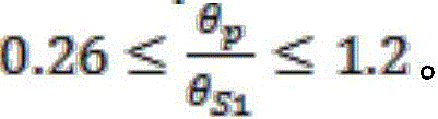
依据本发明的实施例,导光元件的折射率为n1,第一反射面的曲率半径为RS1,出射反射面的曲率半径为RS2,光学系统符合
依据本发明的实施例,显示屏的中心入射第一反射面的光线高度为HS1,第一反射面的曲率半径为RS1,光学系统符合
依据本发明的实施例,导光元件和一辅助镜片组合成一镜片,第二反射面与辅助镜片邻接。According to an embodiment of the present invention, the light guide element and an auxiliary lens are combined into a lens, and the second reflective surface is adjacent to the auxiliary lens.
依据本发明的实施例,镜片的形状与一增强现实的眼镜的镜框相符。According to an embodiment of the present invention, the shape of the lens conforms to the frame of an augmented reality glasses.
附图说明Description of drawings
图1及图2为本发明具增强现实的光学系统的镜片的立体图。1 and 2 are perspective views of a lens with an augmented reality optical system according to the present invention.
图3及图4为本发明具增强现实的光学系统的光学路径及角度的示意图。3 and 4 are schematic diagrams of optical paths and angles of the optical system with augmented reality of the present invention.
图5为本发明具增强现实的光学系统应用在眼镜上的示意图。FIG. 5 is a schematic diagram of the application of the augmented reality optical system in glasses according to the present invention.
图6及图7为将图5的眼镜配戴在人脸上的示意图。6 and 7 are schematic diagrams of wearing the glasses of FIG. 5 on a human face.
图8至图11为本发明具增强现实的光学系统的其他实施例的示意图。8 to 11 are schematic diagrams of other embodiments of the optical system with augmented reality of the present invention.
附图标记列表:10-具增强现实的光学系统;12-显示屏;14-镜片;142-导光元件;144-辅助镜片;162-入射面;164-第一反射面;166-出射反射面;168-第二反射面;18-人眼;20-镜框。List of reference signs: 10—optical system with augmented reality; 12—display screen; 14—mirror; 142—light guide element; 144—auxiliary lens; 168-the second reflective surface; 18-human eyes; 20-frame.
具体实施方式Detailed ways
本发明提供一种具增强现实的光学系统,其可应用在近视眼镜、平光眼镜或远视眼镜,使这三种眼镜兼具增强现实的效果,让使用者方便配戴。此外,更通过将显示屏设置在镜片上方的设计,使导光元件的厚度轻薄仍可达到增强现实的效果,让整体光学系统更为轻薄。The present invention provides an optical system with augmented reality, which can be applied to myopia glasses, plano glasses or hyperopia glasses, so that these three kinds of glasses can have the effect of augmented reality, making it convenient for users to wear them. In addition, through the design of setting the display screen above the lens, the thickness of the light guide element can still achieve the effect of augmented reality, making the overall optical system thinner and lighter.
请同时参考图1、图2、图3及图4,其中图1及图2为本发明具增强现实的光学系统10的镜片14的立体图,图3及图4为本发明具增强现实的光学系统10的光学路径及角度的示意图。本发明的具增强现实的光学系统10包括一显示屏12及一导光元件142,其中显示屏12用以发出光线,特别是包含影像的影像光;导光元件142为片状,包括一入射面162及多个反射面,入射面162设于导光元件142的顶端,显示屏12与入射面162相对设置,从入射面162的上方发出光线,光线向下从入射面162进入导光元件142。光线在导光元件142内经过三次反射后,被导光元件142导入人眼18。Please refer to Fig. 1, Fig. 2, Fig. 3 and Fig. 4 at the same time, wherein Fig. 1 and Fig. 2 are perspective views of
更具体来说,入射面162为倾斜面,显示屏12与入射面162平行。反射面包括一第一反射面164、一出射反射面166及一第二反射面168。其中,第一反射面164与出射反射面166相对设置,出射反射面166为靠近人眼18的表面,第一反射面164则为远离人眼18的表面。入射面162与第一反射面164及出射反射面166相邻。更进一步来说,第一反射面164及出射反射面166为轴对称曲面,第一反射面164及出射反射面166的对称轴为同轴设置。出射反射面166分为两个部分,上半部为反射面,下半部则为出射面。第二反射面168设于导光元件142的底部,为一倾斜面。当光线穿透入射面162后,依序被第一反射面164、出射反射面166及第二反射面168反射后导入人眼18。More specifically, the
本发明设置三个反射面的原因在于,若只有两次反射,则导光元件142的厚度需要更厚才能达到良好的像差修正。若反射三次,则导光元件142可更薄而达到好的像差修正效果。The reason why the present invention provides three reflective surfaces is that if there are only two reflections, the thickness of the
第二反射面168设有一部分穿透部分反射的镀膜(图中未示),因此第二反射面168具有部分穿透部分反射的效果。当显示屏12发出光线时,到达第二反射面168的光线会部分穿透第二反射面168射向前方,部分则反射向人眼18。当显示屏12没有启动时,则人眼18可直接通过第一反射面164或第二反射面168看到外界影像。The second
光线的详细路径如下:光线穿透入射面162后,被第一反射面164全反射至出射反射面166的上半部。由于出射反射面166的上半部为反射面,因此被第一反射面164全反射的光线会再次被出射反射面166的上半部进行全反射,反射到第二反射面168。当出射反射面166的上半部所反射的光线经过第二反射面168后,会进行部分穿透部分反射,其中,被第二反射面168部分反射的光线会穿透出射反射面166的下半部,到达人眼18,让人眼18看到显示屏12所显示的影像、同时看到外界影像,达到增强现实的目的。The detailed path of the light is as follows: after the light passes through the
导光元件142和一辅助镜片144组合成一镜片14,导光元件142底部的第二反射面168与辅助镜片144邻接,通过与导光元件142的底部贴合、黏合或其它方式组合在一起。设置辅助镜片144的目的是为了使镜片14的形状与一增强现实的眼镜的镜框相符。且由于使用者也会通过辅助镜片144看到外部影像,因此,在材质选择上,辅助镜片144会与导光元件142一致。因为若辅助镜片144与导光元件142的材质不一致,则折射率也不同,使用者通过镜片看到外界景像会因为镜片光程差的差异而造成景象不连续。使用者可直接配戴包含本发明的具增强现实的光学系统10的眼镜,无须在原有的近视眼镜或远视眼镜及增强现实的眼镜之间切换配戴。The
本发明中,入射面162、第一反射面164、出射反射面166及第二反射面168为球面、非球面或平面其中之一。当入射面162、第一反射面164、出射反射面166及第二反射面168为球面时,具增强现实的光学系统10符合公式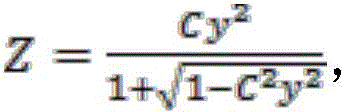

本发明中为了使人眼18可通过导光元件142看到外界影像,也就是外界光会先通过第一反射面164再通过出射反射面166到达人眼18,进而使具增强现实的光学系统10的眼镜兼具增强现实的眼镜及近视眼镜、远视眼镜或平光眼镜的效果。因此,利用第一反射面164与出射反射面166间的曲率搭配,使导光元件142具有屈光度,屈光度的范围在正负8度之间。In the present invention, in order to enable the
此外,由于显示屏12为倾斜的,因此还需定义显示屏12的倾斜角及其入射到第一反射面164的夹角。假设显示屏12与Y轴的夹角为θp,从显示屏12的中心入射第一反射面164的光线的入射角为θS1,则具增强现实的光学系统10符合
此外,由于光线在导光元件142内部经过折射与反射,因此需要定义导光元件142的折射率及第一反射面164、出射反射面166的曲率半径之间的关系。假设导光元件142的折射率为n1,第一反射面164的曲率半径为RS1,出射反射面166的曲率半径为RS2,则具增强现实的光学系统10符合
再者,光线进入导光元件142后触及的第一个面,也就是触及到第一反射面164的位置与人眼18之间的距离(高度)也是一个重要的参数,其代表导光元件142的纵向长度是否够短,不会超过一般眼镜片的纵向长度。而要调整显示屏12的中心入射第一反射面164的光线高度HS1,还需要配合调整第一反射面的曲率半径为RS1,在本发明中,当具增强现实的光学系统10符合
图5为本发明具增强现实的光学系统应用在眼镜上的示意图。如图所示,镜片14为导光元件142及辅助镜片144的组合,且组合后的尺寸符合镜框20的大小。镜框20的左右两边分别设置有一显示屏12。将图5的眼镜配戴在人脸上,如图6及图7所示。使用者配戴此眼镜时,若显示屏12未启用,一般情况可当作平光眼镜、近视眼镜或远视眼镜使用。当显示屏12发出影像光时,使用者便可看到增强现实的影像。FIG. 5 is a schematic diagram of the application of the augmented reality optical system in glasses according to the present invention. As shown in the figure, the
图8至图11为不同镜片14的实施例,其中图8为第一实施例,其镜片14为平光眼镜的镜片。图9为第二实施例,其镜片14也是平光眼镜的镜片。图10为第三实施例,其镜片14为-2.25度的近视眼镜的镜片。图11为第四实施例,其镜片14为+2.75度的远视眼镜的镜片。各实施例的参数如下表一,对应公式的最佳数值如下表二:8 to 11 are different embodiments of the
表一Table I
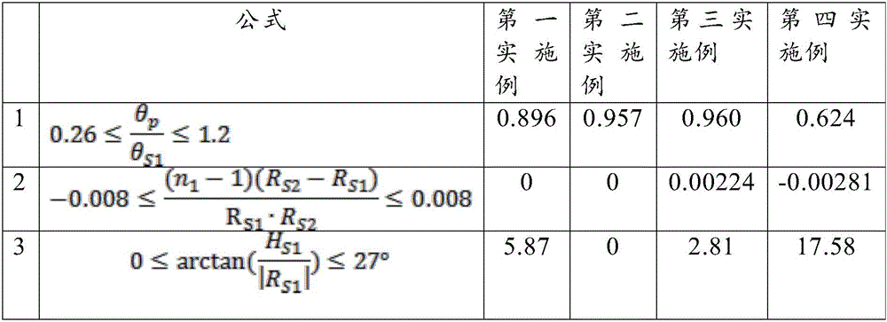
表二Table II
综上所述,本发明所提供的具增强现实的光学系统可应用在近视眼镜、平光眼镜或远视眼镜,使这三种眼镜兼具增强现实的效果,让使用者方便配戴。此外,由于一般显示屏水平较长垂直较短,因此本发明将显示屏设置在镜片上方的设计,缩短导光元件的高度,使导光元件的高度及厚度皆轻薄仍可达到增强现实的效果,使增强现实的眼镜更轻薄。再者,此光学系统中无任何绕射、干涉元件与自由曲面,只用非球面与球面或平面,因此结构单纯并能达到良好的像差修正,且制造性较高。在功能性上,使用本发明的光学系统的增强现实的眼镜能同时达到屈光矫正的要求。To sum up, the optical system with augmented reality provided by the present invention can be applied to myopia glasses, plain vision glasses or hyperopia glasses, so that these three kinds of glasses can also have the effect of augmented reality, making it easy for users to wear them. In addition, because the general display screen is longer horizontally and shorter vertically, the design of the present invention arranges the display screen above the lens, shortens the height of the light guide element, makes the height and thickness of the light guide element light and thin, and can still achieve the effect of augmented reality , making augmented reality glasses thinner and lighter. Furthermore, the optical system does not have any diffraction or interference elements or free-form surfaces, and only uses aspheric surfaces, spherical surfaces or flat surfaces. Therefore, the structure is simple and can achieve good aberration correction, and the manufacturability is high. In terms of functionality, the augmented reality glasses using the optical system of the present invention can meet the requirements of refractive correction at the same time.
唯以上所述者,仅为本发明的较佳实施例而已,并非用来限定本发明实施的范围。故即凡依本发明申请范围所述的特征及精神所为的均等变化或修饰,均应包括于本发明的申请专利范围内。The above-mentioned ones are only preferred embodiments of the present invention, and are not intended to limit the implementation scope of the present invention. Therefore, all equivalent changes or modifications based on the features and spirit described in the scope of the application of the present invention shall be included in the scope of the patent application of the present invention.
Claims (19)


Priority Applications (1)
| Application Number | Priority Date | Filing Date | Title |
|---|---|---|---|
| CN202111014717.8A CN115728942A (en) | 2021-08-31 | 2021-08-31 | Optical system with augmented reality |
Applications Claiming Priority (1)
| Application Number | Priority Date | Filing Date | Title |
|---|---|---|---|
| CN202111014717.8A CN115728942A (en) | 2021-08-31 | 2021-08-31 | Optical system with augmented reality |
Publications (1)
| Publication Number | Publication Date |
|---|---|
| CN115728942A true CN115728942A (en) | 2023-03-03 |
Family
ID=85291555
Family Applications (1)
| Application Number | Title | Priority Date | Filing Date |
|---|---|---|---|
| CN202111014717.8A Pending CN115728942A (en) | 2021-08-31 | 2021-08-31 | Optical system with augmented reality |
Country Status (1)
| Country | Link |
|---|---|
| CN (1) | CN115728942A (en) |
Citations (11)
| Publication number | Priority date | Publication date | Assignee | Title |
|---|---|---|---|---|
| EP1465003A1 (en) * | 1999-04-02 | 2004-10-06 | Olympus Corporation | Viewing optical system and image display apparatus using the same |
| CN101097293A (en) * | 2006-06-29 | 2008-01-02 | 贾怀昌 | Free-form surface total reflection type visual optical prism and its emergent optical axis parallelism adjusting mechanism |
| CN101153958A (en) * | 2006-09-26 | 2008-04-02 | 深圳国际技术创新研究院 | Novel glasses type displayer |
| US20150177519A1 (en) * | 2013-12-19 | 2015-06-25 | Google Inc. | See-through eyepiece for head wearable display |
| CN205157873U (en) * | 2015-11-27 | 2016-04-13 | 上海渺视光学科技有限公司 | A glasses for penetration demonstration |
| CN105824121A (en) * | 2015-01-06 | 2016-08-03 | 广州南北电子科技有限公司 | Optical system and video glasses |
| CN107976807A (en) * | 2016-11-25 | 2018-05-01 | 上海渺视光学科技有限公司 | A kind of augmented reality formula head-mounted display and its light channel structure |
| CN109814262A (en) * | 2019-01-22 | 2019-05-28 | 深圳市数泽科技有限公司 | A kind of miniscope imaging optical system and the equipment for having VR/AR function |
| CN109884796A (en) * | 2019-03-26 | 2019-06-14 | 深圳创龙智新科技有限公司 | A kind of optical glasses |
| CN110208950A (en) * | 2019-07-12 | 2019-09-06 | 北京耐德佳显示技术有限公司 | A kind of glasses and its optical module shown for augmented reality |
| CN215769212U (en) * | 2021-08-31 | 2022-02-08 | 双莹科技股份有限公司 | Optical system with augmented reality |
-
2021
- 2021-08-31 CN CN202111014717.8A patent/CN115728942A/en active Pending
Patent Citations (11)
| Publication number | Priority date | Publication date | Assignee | Title |
|---|---|---|---|---|
| EP1465003A1 (en) * | 1999-04-02 | 2004-10-06 | Olympus Corporation | Viewing optical system and image display apparatus using the same |
| CN101097293A (en) * | 2006-06-29 | 2008-01-02 | 贾怀昌 | Free-form surface total reflection type visual optical prism and its emergent optical axis parallelism adjusting mechanism |
| CN101153958A (en) * | 2006-09-26 | 2008-04-02 | 深圳国际技术创新研究院 | Novel glasses type displayer |
| US20150177519A1 (en) * | 2013-12-19 | 2015-06-25 | Google Inc. | See-through eyepiece for head wearable display |
| CN105824121A (en) * | 2015-01-06 | 2016-08-03 | 广州南北电子科技有限公司 | Optical system and video glasses |
| CN205157873U (en) * | 2015-11-27 | 2016-04-13 | 上海渺视光学科技有限公司 | A glasses for penetration demonstration |
| CN107976807A (en) * | 2016-11-25 | 2018-05-01 | 上海渺视光学科技有限公司 | A kind of augmented reality formula head-mounted display and its light channel structure |
| CN109814262A (en) * | 2019-01-22 | 2019-05-28 | 深圳市数泽科技有限公司 | A kind of miniscope imaging optical system and the equipment for having VR/AR function |
| CN109884796A (en) * | 2019-03-26 | 2019-06-14 | 深圳创龙智新科技有限公司 | A kind of optical glasses |
| CN110208950A (en) * | 2019-07-12 | 2019-09-06 | 北京耐德佳显示技术有限公司 | A kind of glasses and its optical module shown for augmented reality |
| CN215769212U (en) * | 2021-08-31 | 2022-02-08 | 双莹科技股份有限公司 | Optical system with augmented reality |
Similar Documents
| Publication | Publication Date | Title |
|---|---|---|
| JP6595619B2 (en) | Efficient thin curved eyepiece for see-through head wearable display | |
| US9915823B1 (en) | Lightguide optical combiner for head wearable display | |
| CN104423044B (en) | virtual image display device | |
| CN114325903B (en) | A free-form surface prism assembly and a near-eye display device using the same | |
| KR101421199B1 (en) | Lens system for head mounted display | |
| CN112327495B (en) | Light guide body, virtual image optical system and virtual image display device | |
| JP2018528446A (en) | Addition of prescription correction to eyepiece for see-through head wearable display | |
| JP2020008749A (en) | Head mounted display | |
| US11175483B2 (en) | Wide field of view head mounted display | |
| US11754836B2 (en) | Optical system for AR headsets, and method for design and manufacturing | |
| CN109073896B (en) | Spectacle lenses for imaging optical units and data goggles | |
| US20200049964A1 (en) | Optical system and image enlargement device | |
| US20170276946A1 (en) | Image display device | |
| CN215117019U (en) | Optical lens group and near-to-eye display device | |
| JP4667655B2 (en) | Optical element and optical apparatus using the same | |
| KR101362873B1 (en) | Lens system for head mounted display | |
| CN215769212U (en) | Optical system with augmented reality | |
| US7675685B2 (en) | Image display apparatus | |
| CN109425986A (en) | Head-mounted display device and imaging lens | |
| US11966058B2 (en) | Ultra-thin lens, virtual image display device using same, and near-eye display | |
| TWI779789B (en) | Optical system with augmented reality | |
| CN115728942A (en) | Optical system with augmented reality | |
| CN110286490A (en) | Augmented reality optical system based on free-form surface and optical waveguide | |
| TWM620253U (en) | Augmentation real environment optical system | |
| CN110955053B (en) | Near-to-eye display system based on positive defocus |
Legal Events
| Date | Code | Title | Description |
|---|---|---|---|
| PB01 | Publication | ||
| PB01 | Publication | ||
| SE01 | Entry into force of request for substantive examination | ||
| SE01 | Entry into force of request for substantive examination | ||
| TA01 | Transfer of patent application right | ||
| TA01 | Transfer of patent application right |
Effective date of registration: 20230412 Address after: Room 102, Building 1, No. 8 Shangsha Zhongnan Road, Chang'an Town, Dongguan City, Guangdong Province, 523000 Applicant after: Dongguan Shuangying Optoelectronic Technology Co.,Ltd. Address before: Taoyuan City, Taiwan, China Applicant before: SHUANGYING TECHNOLOGY Co.,Ltd. Applicant before: Dongguan Shuangying Photoelectric Technology Co.,Ltd. |