CN115723831A - Linkage folding mechanism and child carrier - Google Patents
Linkage folding mechanism and child carrier Download PDFInfo
- Publication number
- CN115723831A CN115723831A CN202111022636.2A CN202111022636A CN115723831A CN 115723831 A CN115723831 A CN 115723831A CN 202111022636 A CN202111022636 A CN 202111022636A CN 115723831 A CN115723831 A CN 115723831A
- Authority
- CN
- China
- Prior art keywords
- gear
- rod
- seat
- support bar
- fixed
- Prior art date
- Legal status (The legal status is an assumption and is not a legal conclusion. Google has not performed a legal analysis and makes no representation as to the accuracy of the status listed.)
- Pending
Links
Images


Classifications
-
- B—PERFORMING OPERATIONS; TRANSPORTING
- B62—LAND VEHICLES FOR TRAVELLING OTHERWISE THAN ON RAILS
- B62B—HAND-PROPELLED VEHICLES, e.g. HAND CARTS OR PERAMBULATORS; SLEDGES
- B62B7/00—Carriages for children; Perambulators, e.g. dolls' perambulators
- B62B7/04—Carriages for children; Perambulators, e.g. dolls' perambulators having more than one wheel axis; Steering devices therefor
- B62B7/06—Carriages for children; Perambulators, e.g. dolls' perambulators having more than one wheel axis; Steering devices therefor collapsible or foldable
-
- B—PERFORMING OPERATIONS; TRANSPORTING
- B62—LAND VEHICLES FOR TRAVELLING OTHERWISE THAN ON RAILS
- B62B—HAND-PROPELLED VEHICLES, e.g. HAND CARTS OR PERAMBULATORS; SLEDGES
- B62B2205/00—Hand-propelled vehicles or sledges being foldable or dismountable when not in use
- B62B2205/18—Geared articulations
Landscapes
- Engineering & Computer Science (AREA)
- Chemical & Material Sciences (AREA)
- Combustion & Propulsion (AREA)
- Transportation (AREA)
- Mechanical Engineering (AREA)
- Carriages For Children, Sleds, And Other Hand-Operated Vehicles (AREA)
- Toys (AREA)
Abstract
The invention relates to a linkage folding mechanism and a child carrier. The linkage folding mechanism and the child carrier have simple structures and are not easy to produce stuffing.
Description
Technical Field
The present invention relates to a child carrier, and more particularly, to a folding mechanism and a child carrier.
Background
Children's carrier, children's shallow for example has become the indispensable trip instrument of children's trip, can improve the convenience that children went on a journey greatly. A stroller typically includes a backrest to support the back of the child. In order to reduce the packaging and storage volume, the backrest can be driven to be folded synchronously when the frame of the common stroller is folded. However, the linked folding of the backrest is mostly a link structure, which is complicated and is prone to stuffing, resulting in injury to children or parents.
Disclosure of Invention
Accordingly, there is a need for a folding mechanism and a child carrier, which have simple structure and are not easy to produce stuffing.
One aspect of the present application provides a mechanism is folded in interlock, the mechanism is folded in interlock includes first member, second member, driving piece and follower, the driving piece is fixed in on the first member, the driving piece has first round tooth portion, the follower is fixed in on the second member, the follower has second round tooth portion, first round tooth portion with the meshing of second wheel tooth portion.
In one embodiment, the driving member is fixed to one end of the first rod, and the driven member is fixed to one end of the second rod.
In one embodiment, the interlocking folding mechanism further includes a gear shell pivotally connected to the first rod and covering the first gear portion, the gear shell has an engaging opening facing the second gear portion, and the second gear portion is engaged with the first gear portion through the engaging opening.
In one embodiment, the pinion housing further has an engaging hole, the driving member is fixed to one end of the first rod, the driving member and a part of the first rod extend into the pinion housing through the engaging hole, a hole wall of the engaging hole has a first side and a second side opposite to each other, when the first rod rotates to abut against the first side, an included angle between the first rod and the second rod is minimum, and when the first rod rotates to abut against the second side, an included angle between the first rod and the second rod is maximum.
In one embodiment, the pinion housing includes a housing body and a housing cover body, the housing cover body is detachably covered on a side of the pinion housing facing the second pinion tooth portion, and the engagement opening is opened on the housing cover body.
Another aspect of the present application provides a child carrier, including:
the frame supporting structure comprises a backrest supporting rod and a saddle supporting rod;
the driving piece is fixed on the seat support rod and provided with a first wheel tooth part;
the driven piece is fixed on the backrest support rod and provided with a second gear tooth part, and the first gear tooth part is meshed with the second gear tooth part.
In one embodiment, the frame support structure further comprises a handle assembly, the handle assembly comprises a first handle support rod, a second handle support rod, an operating element and a locking mechanism, the first handle support rod and the second handle support rod are pivoted through the locking mechanism, and the operating element is used for controlling the locking mechanism to switch between a locking state and an unlocking state, so that the first handle support rod and the second handle support rod switch between a relatively fixed state and a relatively rotating state.
In one embodiment, the frame support structure further includes a first connecting member, and the second handle support rod and the seat support rod are pivotally connected to the first connecting member at different positions, respectively.
In one embodiment, the child carrier further includes a wheel tooth shell pivotally connected to the seat support rod and covering the first wheel tooth portion, the wheel tooth shell has an engagement opening facing the second wheel tooth portion, the second wheel tooth portion passes through the engagement opening to engage with the first wheel tooth portion, the first linkage member is an L-shaped structure, a vertex of the L-shaped structure is fixed on the wheel tooth shell, one end of the L-shaped structure away from the vertex is fixed on the seat support rod, and the other end of the L-shaped structure away from the vertex is pivotally connected to the second handle support rod.
In one embodiment, the frame support structure further includes a rear foot support rod and a second linkage, wherein one end of the second linkage is pivotally connected to the seat support rod, and the other end of the second linkage is pivotally connected to the rear foot support rod and the second handle support rod.
In one embodiment, the frame support structure further comprises a front foot assembly pivotally connected to the seat support bar.
In one embodiment, the front foot assembly comprises a first front foot supporting rod, a front foot connector and a second front foot supporting rod which are sequentially pivoted, one end of the first front foot supporting rod, which is far away from the front foot connector, is pivoted on the first hand supporting rod, the front foot connector and the rear foot supporting rod are fixedly connected in an included angle, and the second front foot supporting rod is pivoted with the seat supporting rod.
In one embodiment, the child carrier further comprises a seat plate fixed to the seat support rod.
In one embodiment, there are two frame support structures, two seat support rods of the two frame support structures are respectively fixed on the left and right sides of the seat plate, and there are two driving members and two driven members, respectively for realizing the interlocking folding between the seat support rods and the backrest support rods of the two frame support structures.
In one embodiment, the child carrier further includes an extension plate, a front side of the extension plate is pivotally connected to a rear side of the seat plate, and two ends of the rear side of the extension plate are respectively fixed to the backrest support rods of the two frame support structures.
In one embodiment, the child carrier further comprises a backrest adjusting structure, the backrest adjusting structure comprises an adjusting piece, a rotating seat, a driving piece, a gear and an elastic piece, a first gear groove meshed with the gear is formed in the driven piece, the gear and the rotating seat are coaxially pivoted, the backrest supporting rod is fixed on the rotating seat, the driving piece is in driving connection with the gear, the elastic piece is abutted to the driven piece and the gear, and the adjusting piece is used for driving the driving piece to drive the gear to be separated from the first gear groove.
In the linkage folding mechanism and the child carrier, the first rod piece and the second rod piece are linked and folded through the first gear tooth part on the driving piece and the second gear tooth part on the driven piece, so that when the first rod piece rotates, the second rod piece can be driven to rotate by a corresponding angle, and the linkage folding function is realized. When the first rod is, for example, a seat support rod and the second rod is, for example, a backrest support rod, the seat support rod can be rotated and folded by driving the backrest support rod to rotate and fold. The linkage folding mechanism is simple in structure, replaces a traditional connecting rod structure through the matching of the two gear tooth parts, is not easy to produce stuffing, and is higher in safety factor.
Drawings
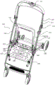
Fig. 1 is a schematic structural view of a child carrier according to an embodiment of the present application;
FIG. 2 is an enlarged view of FIG. 1 at A;
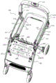
FIG. 3 is a schematic view of the child carrier shown in FIG. 1 from another perspective;
FIG. 4 is an enlarged view of FIG. 3 at B;
FIG. 5 is a schematic view of the child carrier shown in FIG. 1 with the seat plate and armrest omitted;
FIG. 6 is an enlarged view at C of FIG. 5;
FIG. 7 is a side cross-sectional view of the child carrier shown in FIG. 5, with the child carrier in an open position;
FIG. 8 is an enlarged view of FIG. 7 at D;
fig. 9 is a side cross-sectional view of the child carrier shown in fig. 5, with the child carrier in a transition state between an open-position state and a collapsed-position state;
FIG. 10 is an enlarged view at E of FIG. 9;
FIG. 11 is a side cross-sectional view of the child carrier shown in FIG. 5 with the child carrier in a collapsed position;
FIG. 12 is an enlarged view at F of FIG. 11;
FIG. 13 is an enlarged view of a portion of FIG. 3;
FIG. 14 is a schematic view of a child carrier according to another embodiment of the present application, with the child carrier in an open position;
fig. 15 is a structural view of the child carrier shown in fig. 14 from another perspective when the child carrier is in a retracted position;
FIG. 16 is a partial schematic view of the child carrier shown in FIG. 14;
fig. 17 is an exploded view of fig. 16.
Description of the reference numerals
100. A frame support structure, 110, a handlebar assembly, 111, a first handlebar support rod, 112, a second handlebar support rod, 113, an operating member, 114, a locking mechanism, 120, a seat support rod, 130, a rear leg support rod, 140, a front leg assembly, 141, a first front leg support rod, 142, a front leg link, 143, a second front leg support rod, 150, a backrest support rod, 160, a first link, 170, a second link, 180, a backrest adjustment structure, 181, an adjustment member, 182, a swivel, 183, a driving block, 184, a gear, 185, an elastic member, 190, an armrest, 200, a driving member, 210, a first gear tooth portion, 300, a driven member, 310, a second gear tooth portion, 320, a fixed seat, 330, a driven body, 340, a gear tooth slot, 400, a gear tooth shell, 411, an engagement port, 412, an engagement hole, 450, a shell body, 460, a shell cover body, 500, a seat plate, 600, an extension plate, 10, a first rod, 20, and a second rod.
Detailed Description
As shown in fig. 1, 7 and 8, an embodiment of the present application provides a child carrier, such as a stroller, including a frame supporting structure 100, a driving member 200, a driven member 300, a gear housing 400 and a seat plate 500. The child carrier is simple in structure, not easy to produce stuffing when folded and high in safety factor.
Specifically, as shown in fig. 1 and 2, the frame supporting structure 100 includes a handlebar assembly 110, a seat supporting bar 120, a rear foot supporting bar 130, a front foot assembly 140, a backrest supporting bar 150, a first linkage 160, a second linkage 170, a backrest adjusting structure 180, and an armrest 190.
The rider assembly 110 includes a first rider support bar 111, a second rider support bar 112, an operating member 113 and a locking mechanism 114. The first hand support rod 111 and the second hand support rod 112 are pivotally connected by a locking mechanism 114, and the operating member 113 is used for controlling the locking mechanism 114 to switch between a locked state and an unlocked state, so that the first hand support rod 111 and the second hand support rod 112 are switched between a relatively fixed state and a relatively rotated state. In this embodiment, the first hand support bar 111 is positioned above the second hand support bar 112 when the stroller is in the open position (i.e., fully open, ready for use).
As shown in fig. 3 and 4, the second handle bar 112 and the seat bar 120 are pivotally connected to the first link 160 at different positions. The first linking member 160 can realize the linking folding between the second handlebar 112 and the seat bar 120, i.e. when the second handlebar 112 rotates, the seat bar 120 rotates accordingly.
In this embodiment, as shown in fig. 4 and 13, the first linking member 160 is an iron plate with a substantially L-shaped structure, the vertex of the L-shaped structure is fixed on the gear housing 400, one end of the L-shaped structure away from the vertex is pivotally connected to the seat supporting rod 120, and the other end of the L-shaped structure away from the vertex is pivotally connected to the second handle supporting rod 112. Of course, in other embodiments, the first linking member 160 may have other shapes or materials.
Further, as shown in fig. 4, the second linking member 170 is an iron plate with a substantially strip-shaped structure, and one end of the second linking member 170 is pivotally connected to the seat support bar 120, and the other end is pivotally connected to the rear foot support bar 130 and the second handle support bar 112. The second linking member 170 can realize linking and folding between the seat support rod 120 and the rear foot support rod 130, and when the seat support rod 120 rotates, the rear foot support rod 130 rotates accordingly.
Specifically, as shown in figure 1, the forefoot assembly 140 includes a first forefoot support bar 141, a forefoot coupler 142, and a second forefoot support bar 143 that are pivotally connected in that order. In this embodiment, when the stroller is in the open position, the first front leg support 141, the front leg connector 142 and the second front leg support 143 are sequentially disposed in an inclined manner in the top-to-bottom direction. One end of the first front leg supporting rod 141, which is far away from the front leg connecting member 142, is pivotally connected to the first handlebar supporting rod 111, and a pivot point of the first front leg supporting rod 141 and the first handlebar supporting rod 111 is located at a side of the locking mechanism 114, which is far away from the second handlebar supporting rod 112, i.e., the pivot point of the first front leg supporting rod 141 and the first handlebar supporting rod 111 is spaced from the locking mechanism 114. The front leg connecting member 142 is fixedly connected to the rear leg supporting rod 130 at an included angle, and the second front leg supporting rod 143 is pivotally connected to the seat supporting rod 120. Thus, as shown in fig. 7 to 12, when the operating element 113 is operated, the locking mechanism 114 between the first hand support rod 111 and the second hand support rod 112 is unlocked, the first hand support rod 111 rotates in a counterclockwise direction relative to the locking mechanism 114, and the first front foot support rod 141 rotates in a clockwise direction relative to the front foot connecting member 142 under the driving of the first hand support rod 111. Meanwhile, the second handle bar 112 rotates clockwise relative to the locking mechanism 114, and the first linking member 160 drives the seat bar 120 to rotate counterclockwise relative to the first linking member 160, and the seat bar 120 drives the second front leg bar 143 to rotate counterclockwise relative to the front leg link 142. Meanwhile, the seat support rod 120 drives the rear leg support rod 130 to rotate clockwise relative to the second linkage member 170 through the second linkage member 170, and the rear leg support rod 130 is fixed on the front leg connecting member 142, so the front leg assembly 140 is folded in three sections, and the first front leg support rod 141, the rear leg support rod 130 and the second front leg support rod 143 are folded close to each other, thereby greatly reducing the overall volume of the folded stroller.
Further, as shown in fig. 10, 12 and 14, a driving member 200 is fixed to the seat support rod 120, the driving member 200 having a first gear tooth portion 210. The follower 300 is fixed to the backrest support bar 150, the follower 300 has a second gear portion 310, and the first gear portion 210 is engaged with the second gear portion 310. In this embodiment, the driving member 200 is substantially in the shape of a 1/4 gear, and the central angle of the first gear tooth portion 210 is about 90 degrees. The follower 300 includes a disk-shaped fixing base 320 and a 1/3 gear-shaped driven body 330, the fixing base 320 is fixed to the backrest support rod 150, and specifically, the fixing base 320 and the backrest support rod 150 are engaged with each other through the rotary base 182. The driven body 330 is fixed on the fixing base 320, in this embodiment, the driven body 330 and the fixing base 320 are integrally formed, however, in other embodiments, the driven body 330 and the fixing base 320 may also be assembled together as two independent components. The second gear tooth portion 310 is provided on the driven body 330. Of course, the shapes of the driving member 200 and the driven member 300 are not limited thereto, and the central angles of the first gear tooth portion 210 and the second gear tooth portion 310 may be adjusted according to actual needs. Thus, the seat support rod 120 and the backrest support rod 150 can be folded by the first gear portion 210 of the driving member 200 and the second gear portion 310 of the driven member 300. Specifically, in the folding process, when the seat supporting rod 120 is driven by the first linking member 160 to rotate in the counterclockwise direction relative to the first linking member 160, the backrest supporting rod 150 rotates in the clockwise direction relative to the driving member, so that the seat supporting rod 120 and the backrest supporting rod 150 approach each other to be folded. The traditional connecting rod structure is replaced by the matching of the two gear tooth parts, the structure is simple, stuffing is not easy to generate, and the safety factor is higher.
Further, the driving member 200 is fixed to one end of the seat support bar 120, and the driven member 300 is fixed to one end of the backrest support bar 150. Thus, on the one hand, the manufacturing and processing can be facilitated, and on the other hand, the moment of the seat support rod 120 in the linkage rotation process can be increased, so that the rotation of the backrest support rod 150 can be driven only by applying a small force to the seat support rod 120.
Further, as shown in fig. 8 and 13, a gear housing 400 is pivotally connected to the seat support rod 120 and covers the first gear portion 210, the gear housing 400 has an engagement opening 411, and the second gear portion 310 is engaged with the first gear portion 210 through the engagement opening 411. The gear housing 400 covers the first gear tooth portion 210 and the second gear tooth portion 310, so that a user can be prevented from being scratched by the first gear tooth portion 210 and the second gear tooth portion 310, and safety is improved.
Alternatively, as shown in fig. 4 and 8, the gear housing 400 further has an engagement hole 412, the driving member 200 is fixed to one end of the seat support rod 120, and the driving member 200 and a portion of the seat support rod 120 are inserted into the gear housing 400 through the engagement hole 412. The hole wall of the engaging hole 412 has a first side and a second side opposite to each other, and when the seat support rod 120 rotates to abut against the first side, the included angle between the seat support rod 120 and the backrest support rod 150 is minimum, and the stroller is in an open position. When the seat support rod 120 rotates to abut against the second side, the included angle between the seat support rod 120 and the backrest support rod 150 is the largest, and the stroller is folded in place. Thus, the rotation angle of the seat support bar 120 can be restricted.
Alternatively, as shown in fig. 6 and 13, the gear tooth housing 400 includes a housing body 450 and a housing cover body 460, and the housing cover body 460 is detachably housed at one side surface of the housing body 450. Thus, the driving member 200 can be easily removed and replaced. In this embodiment, the driven body 330 is disposed in the housing body 450, the fixing base 320 is covered on one side of the housing body 450, and the housing cover 460 is covered on the other side of the housing cover 460.
Further, as shown in fig. 1 to 4, the seat plate 500 is fixed to the seat support rod 120. In this embodiment, there are two frame support structures 100, the seat support rods 120 of the two frame support structures 100 are respectively fixed on the left and right sides of the seat plate 500, and there are two driving members 200 and two driven members 300, which are respectively used for realizing the linkage and folding between the seat support rods 120 and the backrest support rods 150 of the two frame support structures 100.
Specifically, as shown in fig. 16 and 17, the backrest adjusting structure 180 includes an adjusting member 181, a rotating seat 182, a driving block 183, a gear 184, and an elastic member 185. The follower 300 is provided with a first gear groove 340 engaged with the gear 184, and the rotary base is provided with a second gear groove engaged with the gear 184. The driven member 300, the gear 184 and the rotating base 182 are coaxially pivoted, the backrest support rod 150 is fixed on the rotating base 182, the driving block 183 is in driving connection with the gear 184, the elastic member 185 abuts between the driven member 300 and the gear 184, and the adjusting member 181 is used for driving the driving block 183 to drive the gear 184 to be separated from the second gear groove. In this embodiment, the adjusting member 181 is an adjusting iron wire. Thus, when the angle of the backrest support bar 150 needs to be adjusted, the adjusting member 181 can be pulled to drive the driving gear 184 of the driving block 183 to disengage from the second gear groove, and the engagement and locking between the backrest support bar 150 and the driven member 300 are released, so that the angle of the backrest support bar 150 can be adjusted. The elastic member 185 can restore the gear 184 to the engagement lock in the rotary seat 182.
Further, the armrest 190 is a U-shaped rod, and both ends of the armrest 190 are detachably connected to the front foot connecting members 142 of the two frame support structures 100, respectively.
In another embodiment, as shown in fig. 14 and 15, the child carrier further includes an extension panel 600. The front side of the extension board 600 is pivotally connected to the rear side of the seat board 500, and both ends of the rear side of the extension board 600 are respectively fixed to the backrest support bars 150 of the two frame support structures 100. The extension board 600 can be spliced with the seat board 500 to form a wider and comfortable sitting space, and the extension board 600 is pivoted with the seat board 500, and the extension board 600 is fixed to the backrest support bar 150, so that the backrest support bar 150 can drive the extension board 600 to be folded relative to the seat board 500 in the folding process, thereby further reducing the volume of the folded child carrier.
Another embodiment of the present invention provides a linkage folding mechanism, which is suitable for a child carrier, such as a stroller. The linkage folding mechanism has simple structure, is not easy to produce stuffing and has high safety factor.
Specifically, as shown in fig. 8, 10 and 12, the interlocking folding mechanism includes a first rod 10, a second rod 20, a driving member 200, a driven member 300 and a gear shell 400.
The driving member 200 is fixed on the first rod 10, and the driving member 200 has a first toothed portion 210. The follower 300 is fixed to the second rod 20, the follower 300 has a second gear portion 310, and the first gear portion 210 is engaged with the second gear portion 310. The first link 10 may be, for example, a backrest support bar 150 of a stroller, and the second link 20 may be, for example, a seat support bar 120 of the stroller. Of course, the first rod 10 and the second rod 20 may also be other components of the stroller that need to have the interlocking folding function, for example, the first rod 10 may be a handle assembly 110 of the stroller, and the second rod 20 may be a seat support rod 120 of the stroller, and the like, which is not limited thereto. In this embodiment, the driving member 200 is substantially in the shape of a 1/4 gear, and the central angle of the first gear tooth portion 210 is about 90 degrees. The follower 300 includes a disc-shaped fixing base 320 and a driven body 330 in the shape of a 1/3 gear, the fixing base 320 is fixed on the second rod 20, and the driven body 330 is fixed on the fixing base 320. The second gear tooth portion 310 is provided on the driven body 330. The central angle of the first and second gear teeth 210 and 310 can be set to limit the angle between the first and second pins 10 and 20 within a certain range. Of course, the shapes of the driving member 200 and the driven member 300 are not limited thereto, and the central angles of the first gear tooth portion 210 and the second gear tooth portion 310 may be adjusted according to actual needs. In this way, the first rod 10 and the second rod 20 are folded by the first gear tooth 210 on the driving member 200 and the second gear tooth 310 on the driven member 300. The traditional connecting rod structure is replaced by the matching of the two gear tooth parts, the structure is simple, stuffing is not easy to generate, and the safety factor is higher.
Further, a driving member 200 is fixed to one end of the first pin 10, and a driven member 300 is fixed to one end of the second pin 20. Therefore, on one hand, the manufacturing and processing of the interlocking folding mechanism can be facilitated, and on the other hand, the moment of the first rod 10 in the interlocking rotation process can be increased, so that the second rod 20 can be driven to rotate only by applying a small force to the first rod 10.
Further, as shown in fig. 8 and 13, the interlocking folding mechanism further includes a gear housing 400, the gear housing 400 is pivoted to the first rod 10 and covers the first gear portion 210, the gear housing 400 has an engaging opening 411, and the second gear portion 310 passes through the engaging opening 411 and engages with the first gear portion 210. The gear housing 400 covers the first gear tooth portion 210 and the second gear tooth portion 310, so that the user can be prevented from being scratched by the first gear tooth portion 210 and the second gear tooth portion 310, and the safety of the linkage folding mechanism is improved.
Optionally, as shown in fig. 4 and 8, the gear housing 400 further has an engaging hole 412, the driving member 200 is fixed to one end of the first rod 10, the driving member 200 and a portion of the first rod 10 extend into the gear housing 400 through the engaging hole 412, and a wall of the engaging hole 412 has a first side and a second side opposite to each other. When the first rod 10 rotates to abut against the first side, the included angle between the first rod 10 and the second rod 20 is minimum, and the stroller is in an open in-place state; when the first rod 10 rotates to abut against the second side, the included angle between the first rod 10 and the second rod 20 is the largest, and the stroller is folded in place. Thus, the rotation angle of the first pin 10 can be defined.
Alternatively, as shown in fig. 6 and 13, the gear tooth housing 400 includes a housing body 450 and a housing cover body 460, and the housing cover body 460 is detachably housed at one side surface of the housing body 450. Thus, the driving member 200 can be easily removed and replaced. In this embodiment, the driven body 330 is disposed in the housing body 450, the fixing base 320 is covered on one side of the housing body 450, and the housing cover 460 is covered on the other side of the housing cover 460.
The linkage folding mechanism and the child carrier at least have the following advantages:
the first rod 10 and the second rod 20 are folded by the first gear 210 of the driving member 200 and the second gear 310 of the driven member 300, so that when the first rod 10 rotates, the second rod 20 can be driven to rotate by a corresponding angle, thereby achieving the function of folding. When the first rod 10 is, for example, the seat support rod 120 and the second rod 20 is, for example, the backrest support rod 150, the seat support rod 120 can be folded by rotating and the backrest support rod 150 can be folded by rotating. The linkage folding mechanism is simple in structure, replaces a traditional connecting rod structure through the matching of the two gear tooth parts, is not easy to produce stuffing, and is higher in safety factor.
The technical features of the embodiments described above may be arbitrarily combined, and for the sake of brevity, all possible combinations of the technical features in the embodiments described above are not described, but should be considered as being within the scope of the present specification as long as there is no contradiction between the combinations of the technical features.
The above-mentioned embodiments only express several embodiments of the present invention, and the description thereof is more specific and detailed, but not construed as limiting the scope of the invention. It should be noted that various changes and modifications can be made by those skilled in the art without departing from the spirit of the invention, and these changes and modifications are all within the scope of the invention. Therefore, the protection scope of the present patent shall be subject to the appended claims.
Claims (16)
1. The linkage folding mechanism is characterized by comprising a first rod piece, a second rod piece, a driving piece and a driven piece, wherein the driving piece is fixed on the first rod piece and is provided with a first gear tooth part, the driven piece is fixed on the second rod piece and is provided with a second gear tooth part, and the first gear tooth part is meshed with the second gear tooth part.
2. The interlocking folding mechanism of claim 1, wherein the driving member is fixed to an end of the first bar and the driven member is fixed to an end of the second bar.
3. The interlocking folding mechanism according to claim 1, further comprising a gear housing pivotally connected to the first rod and covering the first gear portion, the gear housing having an engaging opening facing the second gear portion, the second gear portion passing through the engaging opening to engage with the first gear portion.
4. The mechanism of claim 3, wherein the ratchet housing further comprises an engaging hole, the driving member is fixed to one end of the first rod, the driving member and a portion of the first rod extend into the ratchet housing through the engaging hole, the engaging hole has a wall with a first side and a second side opposite to each other, when the first rod rotates to abut against the first side, an included angle between the first rod and the second rod is the smallest, and when the first rod rotates to abut against the second side, an included angle between the first rod and the second rod is the largest.
5. The interlocking folding mechanism according to claim 3, wherein the gear case includes a case body and a case cover body, the case cover body is detachably attached to a side of the gear case facing the second gear portion, and the engagement opening is opened in the case cover body.
6. A child carrier, comprising:
the frame support structure comprises a backrest support rod and a seat support rod;
the driving piece is fixed on the seat support rod and provided with a first wheel tooth part;
the driven piece is fixed on the backrest support rod and provided with a second gear tooth part, and the first gear tooth part is meshed with the second gear tooth part.
7. The child carrier of claim 6, wherein the frame support structure further comprises a handlebar assembly including a first handlebar support bar, a second handlebar support bar, an operating member and a locking mechanism, the first handlebar support bar and the second handlebar support bar being pivotally connected by the locking mechanism, the operating member being configured to control the locking mechanism to switch between locked and unlocked states such that the first handlebar support bar and the second handlebar support bar switch between relatively fixed and relatively rotated states.
8. The child carrier of claim 7, wherein the frame support structure further comprises a first linkage member, and the second handlebar and the seat support bar are pivotally connected to the first linkage member at different positions, respectively.
9. The child carrier of claim 8, further comprising a gear housing pivotally connected to the seat support rod and covering the first gear portion, wherein the gear housing has an engagement opening facing the second gear portion, the second gear portion is engaged with the first gear portion through the engagement opening, the first linkage member is an L-shaped structure, an apex of the L-shaped structure is fixed to the gear housing, an end of the L-shaped structure away from the apex is fixed to the seat support rod, and another end of the L-shaped structure away from the apex is pivotally connected to the second handle support rod.
10. The child carrier of claim 8, wherein the frame support structure further comprises a rear foot support bar and a second linkage, wherein one end of the second linkage is pivotally connected to the seat support bar and the other end of the second linkage is pivotally connected to the rear foot support bar and the second handle support bar.
11. The child carrier of claim 10, wherein the frame support structure further comprises a front foot assembly pivotally connected to the seat support bar.
12. The child carrier as claimed in claim 11, wherein the front leg assembly includes a first front leg support bar, a front leg connector and a second front leg support bar pivotally connected in sequence, an end of the first front leg support bar remote from the front leg connector is pivotally connected to the first hand support bar, the front leg connector and the rear leg support bar are fixedly connected at an included angle, and the second front leg support bar is pivotally connected to the seat support bar.
13. The child carrier of claim 8, further comprising a seat plate secured to the seat support post.
14. The child carrier as claimed in claim 13, wherein there are two frame support structures, two seat support rods of the two frame support structures are fixed to the left and right sides of the seat plate, respectively, and there are two driving members and two driven members for interlocking folding between the seat support rods and the backrest support rods of the two frame support structures, respectively.
15. The child carrier of claim 14, further comprising an extension plate, wherein a front side of the extension plate is pivotally connected to a rear side of the seat plate, and wherein two ends of the rear side of the extension plate are respectively fixed to the backrest support rods of the two frame support structures.
16. The child carrier according to any one of claims 6 to 15, further comprising a backrest adjustment structure, wherein the backrest adjustment structure includes an adjustment member, a rotary seat, a driving member, a gear, and an elastic member, the driven member has a first gear groove engaged with the gear, the driven member, the gear, and the rotary seat are coaxially pivoted, the backrest support rod is fixed on the rotary seat, the driving member is in driving connection with the gear, the elastic member abuts between the driven member and the gear, and the adjustment member is configured to drive the driving member to drive the gear to disengage from the first gear groove.
Priority Applications (7)
| Application Number | Priority Date | Filing Date | Title |
|---|---|---|---|
| CN202111022636.2A CN115723831A (en) | 2021-09-01 | 2021-09-01 | Linkage folding mechanism and child carrier |
| TW113105897A TW202423758A (en) | 2021-09-01 | 2022-08-30 | Child carrier |
| TW111132648A TWI836578B (en) | 2021-09-01 | 2022-08-30 | Linked foldable mechanism and children's carrier |
| PCT/EP2022/074270 WO2023031312A1 (en) | 2021-09-01 | 2022-09-01 | Linked foldable mechanism and children's carrier |
| DE112022004176.5T DE112022004176T5 (en) | 2021-09-01 | 2022-09-01 | COUPLED FOLDING MECHANISM AND CHILD CARRIER |
| JP2024513818A JP2024530780A (en) | 2021-09-01 | 2022-09-01 | Link-type folding mechanism and child carrier |
| EP22772489.5A EP4396061A1 (en) | 2021-09-01 | 2022-09-01 | Linked foldable mechanism and children's carrier |
Applications Claiming Priority (1)
| Application Number | Priority Date | Filing Date | Title |
|---|---|---|---|
| CN202111022636.2A CN115723831A (en) | 2021-09-01 | 2021-09-01 | Linkage folding mechanism and child carrier |
Publications (1)
| Publication Number | Publication Date |
|---|---|
| CN115723831A true CN115723831A (en) | 2023-03-03 |
Family
ID=83355612
Family Applications (1)
| Application Number | Title | Priority Date | Filing Date |
|---|---|---|---|
| CN202111022636.2A Pending CN115723831A (en) | 2021-09-01 | 2021-09-01 | Linkage folding mechanism and child carrier |
Country Status (6)
| Country | Link |
|---|---|
| EP (1) | EP4396061A1 (en) |
| JP (1) | JP2024530780A (en) |
| CN (1) | CN115723831A (en) |
| DE (1) | DE112022004176T5 (en) |
| TW (2) | TWI836578B (en) |
| WO (1) | WO2023031312A1 (en) |
Family Cites Families (9)
| Publication number | Priority date | Publication date | Assignee | Title |
|---|---|---|---|---|
| NL1033729C2 (en) * | 2007-04-20 | 2008-10-21 | Maxi Miliaan Bv | Stroller. |
| TW201010894A (en) * | 2008-09-11 | 2010-03-16 | Unique Product & Design Co Ltd | Retractable joint of baby stroller |
| CN103269936B (en) * | 2010-09-01 | 2017-02-22 | 宝得适儿童用品有限公司 | Folding stroller improvements |
| CN104816750B (en) * | 2011-09-05 | 2019-11-19 | 明门香港股份有限公司 | collapsible infant carrier |
| CN104442978B (en) * | 2013-09-17 | 2017-03-01 | 珠海阳光儿童用品有限公司 | The stroller seat folding can be interlocked |
| DE102015115396A1 (en) * | 2015-09-11 | 2017-03-16 | Bumbleride Inc. | buggy |
| EP3762274A4 (en) * | 2018-03-07 | 2022-01-12 | Zhongshan Kingmoon Children Products Co., Ltd. | Stroller |
| CN211196327U (en) * | 2019-12-11 | 2020-08-07 | 珠海阳光儿童用品有限公司 | Baby carriage frame and baby carriage |
| CN111845908A (en) * | 2020-07-09 | 2020-10-30 | 广东吉宝宝儿童用品有限公司 | One-key linkage backrest folding mechanism and backrest folding method thereof |
-
2021
- 2021-09-01 CN CN202111022636.2A patent/CN115723831A/en active Pending
-
2022
- 2022-08-30 TW TW111132648A patent/TWI836578B/en active
- 2022-08-30 TW TW113105897A patent/TW202423758A/en unknown
- 2022-09-01 JP JP2024513818A patent/JP2024530780A/en active Pending
- 2022-09-01 DE DE112022004176.5T patent/DE112022004176T5/en active Pending
- 2022-09-01 EP EP22772489.5A patent/EP4396061A1/en active Pending
- 2022-09-01 WO PCT/EP2022/074270 patent/WO2023031312A1/en active Application Filing
Also Published As
| Publication number | Publication date |
|---|---|
| WO2023031312A1 (en) | 2023-03-09 |
| EP4396061A1 (en) | 2024-07-10 |
| TW202311094A (en) | 2023-03-16 |
| JP2024530780A (en) | 2024-08-23 |
| DE112022004176T5 (en) | 2024-08-08 |
| TW202423758A (en) | 2024-06-16 |
| TWI836578B (en) | 2024-03-21 |
Similar Documents
| Publication | Publication Date | Title |
|---|---|---|
| US8950761B2 (en) | Collapsible child carrier apparatus | |
| US7832756B2 (en) | Stroller | |
| JP3040496B2 (en) | Folding stroller and folding mechanism used therein | |
| US11696649B2 (en) | Child seat | |
| TW202335901A (en) | Foldable locking mechanism | |
| EP3833592B1 (en) | Unlock device and stroller | |
| CN110667679A (en) | Seat frame assembly, stroller and method of folding the same | |
| US20060103178A1 (en) | Collapsible rocker chair | |
| CN216232516U (en) | Linkage folding mechanism and child carrier | |
| CN115723831A (en) | Linkage folding mechanism and child carrier | |
| CN215245076U (en) | Seat basket | |
| CN113147879A (en) | Foldable seat frame for baby carriage | |
| GB2442127A (en) | Foldable stroller | |
| CN216546334U (en) | Baby carriage with seat folding mechanism | |
| CN215322825U (en) | Foldable seat and stroller | |
| CN211032714U (en) | Seat frame assembly for a stroller and stroller | |
| CN216915979U (en) | Baby carriage joint and baby carriage with same | |
| CN112888617A (en) | Child seat and child conveyance device including the same | |
| CN221642539U (en) | Connecting joint, supporting device for child carrier, and child carrier | |
| TW202440389A (en) | Carrier, armrest installation unit, and heigh adjustment mechanism | |
| CN113386844B (en) | A child stroller | |
| CN202095885U (en) | Multifunctional child seat | |
| CN118722825A (en) | Carrier, armrest mounting unit and height adjustment mechanism | |
| CN115959188A (en) | Baby carriage joint and baby carriage with same | |
| JP4562377B2 (en) | Vehicle seat reclining device |
Legal Events
| Date | Code | Title | Description |
|---|---|---|---|
| PB01 | Publication | ||
| PB01 | Publication | ||
| SE01 | Entry into force of request for substantive examination | ||
| SE01 | Entry into force of request for substantive examination |