CN115721388A - Implant conveying device - Google Patents
Implant conveying device Download PDFInfo
- Publication number
- CN115721388A CN115721388A CN202110983605.7A CN202110983605A CN115721388A CN 115721388 A CN115721388 A CN 115721388A CN 202110983605 A CN202110983605 A CN 202110983605A CN 115721388 A CN115721388 A CN 115721388A
- Authority
- CN
- China
- Prior art keywords
- sleeve
- button
- inner sleeve
- tube
- delivery device
- Prior art date
- Legal status (The legal status is an assumption and is not a legal conclusion. Google has not performed a legal analysis and makes no representation as to the accuracy of the status listed.)
- Pending
Links
Images


Landscapes
- Prostheses (AREA)
Abstract
Description
技术领域technical field
本发明涉及医疗器械技术领域,具体涉及一种植入物输送装置。The invention relates to the technical field of medical instruments, in particular to an implant delivery device.
背景技术Background technique
利用经皮介入技术进行疾病治疗,是医疗领域越来越广泛的治疗方法,具体是通过植入物输送装置携带植入物,如瓣膜、大动脉支架等,经皮植入导入患者体内,输送至病变处,再将植入物释放。The use of percutaneous interventional technology for disease treatment is an increasingly widespread treatment method in the medical field. Specifically, implants are carried by implant delivery devices, such as valves, aortic stents, etc., percutaneously implanted into the patient's body, and delivered to the patient's body. lesion, and then release the implant.
在操作过程中,一般需要输送器具有不同的输送速度,实现慢速或快速释放,但现有装置无法同时实现慢速和快速释放,且存在零件数量过多,结构复杂的问题。In the process of operation, it is generally required that the conveyor has different conveying speeds to realize slow or fast release, but the existing devices cannot realize slow and fast release at the same time, and there are problems of too many parts and complex structure.
发明内容Contents of the invention
本发明的目的是提供一种植入物输送装置,同时实现植入物的慢速和快速释放,既满足植入物的精准植入,又缩短手术时间,提高工作效率,且结构简单,降低生产成本。The purpose of the present invention is to provide an implant delivery device, which realizes slow and rapid release of the implant at the same time, satisfies the precise implantation of the implant, shortens the operation time, improves work efficiency, and has a simple structure and reduces production costs. cost.
为解决上述技术问题,本发明提供一种植入物输送装置,包括输送导管,所述输送导管包括内管和可轴向活动地套装所述内管的外管,所述外管包括轴向连接的大径段和小径段,所述大径段位于所述外管的远端,所述大径段和所述内管之间设置有装载腔;In order to solve the above technical problems, the present invention provides an implant delivery device, which includes a delivery catheter, the delivery catheter includes an inner tube and an outer tube that can axially movably fit the inner tube, and the outer tube includes an axial connection A large-diameter section and a small-diameter section, the large-diameter section is located at the distal end of the outer tube, and a loading chamber is provided between the large-diameter section and the inner tube;
还包括套装所述内管的螺杆部,以及套装所述螺杆部的调节部,所述调节部能够带动所述外管沿轴向移动,所述调节部的内侧壁局部设置有与所述螺杆部外螺纹相匹配的内螺纹,且所述调节部能够在第一位置和第二位置切换:It also includes a screw part that fits the inner tube, and an adjustment part that fits the screw part. The adjustment part can drive the outer tube to move in the axial direction. The inner side wall of the adjustment part is partially provided with a The external thread matches the internal thread, and the adjustment part can be switched between the first position and the second position:
所述调节部在第一位置时,所述内螺纹与所述螺杆部啮合;所述调节部在第二位置时,所述内螺纹与所述螺杆部脱离。When the adjustment part is at the first position, the internal thread is engaged with the screw part; when the adjustment part is at the second position, the internal thread is disengaged from the screw part.
本发明植入物输送装置,通过驱动调节部在第一位置和第二位置之间切换,实现植入物的慢速和快速释放,具体地,调节部处于第一位置时,通过内螺纹与螺杆部啮合,此时,只能转动调节部,调节部沿着螺杆部的轴向缓慢移动,并带动外管沿轴向缓慢移动,装载在装载腔内的植入物被缓慢释放或回收;而当调节部处于第二位置时,内螺纹与螺杆部脱离,此时,调节部处于活动状态,可以带动调节部沿螺杆部的轴向快速移动,并带动外管沿轴向快速移动,实现装载物的快速释放或回收。The implant delivery device of the present invention realizes the slow and fast release of the implant by driving the regulating part to switch between the first position and the second position. Specifically, when the regulating part is in the first position, the inner thread and the The screw part is engaged, at this time, only the adjustment part can be rotated, and the adjustment part moves slowly along the axial direction of the screw part, and drives the outer tube to move slowly along the axial direction, and the implant loaded in the loading chamber is slowly released or recovered; And when the adjustment part is in the second position, the internal thread is separated from the screw part. At this time, the adjustment part is in an active state, which can drive the adjustment part to move quickly along the axial direction of the screw part, and drive the outer tube to move quickly along the axial direction, realizing Quick release or recovery of loads.
因此,本发明植入物输送装置,能够同时实现植入物的快速和慢速释放,既满足植入物的精准释放,又能够缩短手术时间,提高工作效率,且结构简单,降低生产成本。Therefore, the implant delivery device of the present invention can realize fast and slow release of the implant at the same time, which not only satisfies the precise release of the implant, but also shortens the operation time, improves work efficiency, has a simple structure, and reduces production costs.
可选地,所述调节部包括外套筒和内套筒,所述外套筒的周壁设置有与所述内套筒相匹配的开口,所述内套筒插装于所述外套筒内部,所述内套筒的内侧壁在与所述开口相对的位置设置有所述内螺纹,所述内套筒能够沿插装方向在所述第一位置和所述第二位置切换。Optionally, the adjustment part includes an outer sleeve and an inner sleeve, the peripheral wall of the outer sleeve is provided with an opening matching the inner sleeve, and the inner sleeve is inserted into the outer sleeve Inside, the inner side wall of the inner sleeve is provided with the inner thread at a position opposite to the opening, and the inner sleeve can be switched between the first position and the second position along the insertion direction.
可选地,还包括沿插装方向设置于所述外套筒和所述内套筒之间的第一弹性件,所述外套筒内部设置有两个沿插装方向延伸的第一安装槽,所述内套筒外侧壁对应位置设置有两个抵柱,所述第一弹性件部分插装于所述第一安装槽内,并且与所述抵柱相抵。Optionally, it also includes a first elastic member arranged between the outer sleeve and the inner sleeve along the insertion direction, and two first installation parts extending along the insertion direction are arranged inside the outer sleeve. The outer side wall of the inner sleeve is provided with two abutting columns at corresponding positions, and the first elastic member is partially inserted into the first installation groove and abuts against the abutting columns.
可选地,所述调节部还包括第一按钮和第一手柄壳体,所述第一手柄壳体套装所述螺杆部以及所述外套筒,且所述第一手柄壳体的内侧壁与所述外套筒固定,并且所述第一手柄壳体与所述外套筒的所述开口对应的位置设置有第一卡槽,所述第一按钮可活动地卡装于所述第一卡槽内,所述第一按钮能够抵压所述内套筒以切换至所述第二位置。Optionally, the adjusting part further includes a first button and a first handle housing, the first handle housing covers the screw part and the outer sleeve, and the inner side wall of the first handle housing It is fixed with the outer sleeve, and the position of the first handle housing corresponding to the opening of the outer sleeve is provided with a first slot, and the first button is movably snapped into the first In a card slot, the first button can press against the inner sleeve to switch to the second position.
可选地,所述调节部还包括设置于所述内套筒下方的第二按钮,所述第二按钮面向所述内套筒的侧壁设置有凸台,所述第二按钮可沿轴向活动,并且在第三位置和第四位置切换:Optionally, the adjusting part further includes a second button arranged below the inner sleeve, a boss is provided on the side wall of the second button facing the inner sleeve, and the second button can be positioned along the shaft. towards the activity, and switch between the third and fourth positions:
所述第二按钮在所述第三位置时,所述凸台与所述内套筒的周壁相抵,所述内套筒处于所述第一位置;所述第二按钮在所述第四位置时,所述凸台与所述内套筒沿轴向错开,所述内套筒可沿径向活动。When the second button is in the third position, the boss abuts against the peripheral wall of the inner sleeve, and the inner sleeve is in the first position; the second button is in the fourth position , the boss and the inner sleeve are axially staggered, and the inner sleeve can move radially.
可选地,所述第一手柄壳体对应位置设置有第二卡槽,所述第二按钮可沿轴向活动地卡装于所述第二卡槽内,还包括第二弹性件,所述外套筒内部设置有一个沿轴向延伸的第二安装槽,所述第二弹性件部分插装于所述第二安装槽内,并与所述第二按钮相抵,所述第二弹性件处于压缩状态,提供所述凸台处于所述第三位置的复位力。Optionally, the first handle housing is provided with a second card slot at a corresponding position, and the second button can be movably locked in the second card slot along the axial direction, and also includes a second elastic member, so that A second mounting groove extending axially is provided inside the outer sleeve, and the second elastic part is partially inserted into the second mounting groove and abuts against the second button. The second elastic The component is in a compressed state, providing a restoring force for the boss to be in the third position.
可选地,还包括套装所述内管的连接件,所述连接件与所述外管连接,所述连接件与所述调节部沿轴向限位连接,周向可转动,所述调节部相对所述螺杆部沿轴向移动时带动所述连接件轴向移动,所述连接件带动所述外管沿轴向移动。Optionally, it also includes a connecting piece that fits the inner tube, the connecting piece is connected with the outer tube, the connecting piece is connected with the adjustment part in an axial limit, and can rotate in the circumferential direction. When the part moves axially relative to the screw part, it drives the connecting part to move axially, and the connecting part drives the outer tube to move axially.
可选地,所述连接件远端和所述外管的近端固定连接,所述连接件近端与所述第一手柄壳体的内侧壁,一者设有沿周向延伸的限位槽,另一者设有插入所述限位槽的凸起,二者通过所述限位槽和所述凸起配合实现沿轴向限位连接。Optionally, the distal end of the connecting piece is fixedly connected to the proximal end of the outer tube, and the proximal end of the connecting piece is connected to the inner side wall of the first handle housing, and one of them is provided with a limiting position extending in the circumferential direction. groove, and the other is provided with a protrusion inserted into the limiting groove, and the two realize axially limiting connection through the cooperation of the limiting groove and the protrusion.
可选地,所述螺杆部设置有沿轴向延伸的导向缺口,所述连接件包括主体套筒部,所述主体套筒部设置有径向延伸的抵顶部,所述主体套筒部位于所述内管和所述螺杆部之间,所述抵顶部穿过所述导向缺口,所述抵顶部为所述凸起。Optionally, the screw part is provided with a guide notch extending in the axial direction, the connecting piece includes a main body sleeve part, and the main body sleeve part is provided with a radially extending abutment part, and the main body sleeve part is located at Between the inner tube and the screw part, the abutment part passes through the guide notch, and the abutment part is the protrusion.
可选地,还包括设置于所述螺杆部远端或近端的限位部件,以及第二手柄壳体,所述第二手柄壳体封装所述限位部件,并与所述限位部件固定连接。Optionally, it also includes a limiting component arranged at the distal end or proximal end of the screw part, and a second handle housing, the second handle housing encapsulates the limiting component, and is connected with the limiting component Fixed connection.
可选地,所述内管包括内层软管和固定套装所述内层软管的中层管,所述内层软管的远端穿出所述中层管,并与远端尖头端固定连接,所述内层软管的近端穿出所述中层管,并与鲁尔接头连接;Optionally, the inner tube includes an inner tube and a middle tube fixedly covering the inner tube, and the distal end of the inner tube passes through the middle tube and is fixed to the tip of the distal end connected, the proximal end of the inner hose passes through the middle tube and is connected with a Luer connector;
或,还包括沿轴向固定连接于所述螺杆部近端的圆管,以及固定于所述圆管近端的尾手柄壳体,所述中层管的近端与所述尾手柄壳体固定连接。Or, it also includes a circular tube fixedly connected to the proximal end of the screw part in the axial direction, and a tail handle housing fixed to the proximal end of the circular tube, and the proximal end of the middle tube is fixed to the tail handle housing connect.
附图说明Description of drawings
图1为本发明所提供植入物输送装置一种具体实施例的结构示意图;Fig. 1 is a schematic structural view of a specific embodiment of an implant delivery device provided by the present invention;
图2为图1植入物输送装置的局部轴向剖视图;Figure 2 is a partial axial sectional view of the implant delivery device of Figure 1;
图3为图2的局部放大示意图;Figure 3 is a partial enlarged schematic view of Figure 2;
图4为图1植入物输送装置中内管和螺杆部的结构示意图;Fig. 4 is a schematic structural view of the inner tube and the screw part of the implant delivery device in Fig. 1;
图5为图1植入物输送装置中调节部的结构示意图;Fig. 5 is a schematic structural view of the regulating part in the implant delivery device of Fig. 1;
图6为图5调节部中外套筒的结构示意图;Fig. 6 is a schematic structural view of the outer sleeve in the adjustment part of Fig. 5;
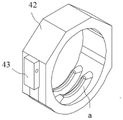
图7为图5调节部中内套筒的结构示意图;Fig. 7 is a schematic structural view of the inner sleeve in the adjustment part of Fig. 5;
图8为图5调节部中第一按钮的结构示意图;Fig. 8 is a schematic structural diagram of the first button in the adjustment part of Fig. 5;
图9为图5调节部中第二按钮的结构示意图;Fig. 9 is a schematic structural diagram of the second button in the adjustment part of Fig. 5;
图10为快速释放时调节部的状态图;Fig. 10 is a state diagram of the regulating part during quick release;
图11为慢速释放时调节部的状态图;Fig. 11 is a state diagram of the regulating part during slow release;
图12为图1植入物输送装置的第一手柄壳体第一部分的结构示意图;Fig. 12 is a schematic structural view of the first part of the first handle housing of the implant delivery device in Fig. 1;
图13为图1植入物输送装置的第一手柄壳体第二部分的结构示意图;Fig. 13 is a schematic structural view of the second part of the first handle housing of the implant delivery device in Fig. 1;
图14为图1植入物输送装置中连接件的结构示意图;Fig. 14 is a schematic structural view of the connector in the implant delivery device of Fig. 1;
图15为图1植入物输送装置中外管的结构示意图;Fig. 15 is a schematic structural view of the outer tube in the implant delivery device of Fig. 1;
图16为图1植入物输送装置中第二手柄壳体第一部分的结构示意图;Fig. 16 is a schematic structural view of the first part of the second handle housing in the implant delivery device in Fig. 1;
图17为图1植入物输送装置中第二手柄壳体第二部分的结构示意图;Fig. 17 is a schematic structural view of the second part of the second handle housing in the implant delivery device in Fig. 1;
图18为图1植入物输送装置中圆管的结构示意图;Fig. 18 is a schematic structural view of the circular tube in the implant delivery device of Fig. 1;
图19为图1植入物输送装置中尾手柄壳体的结构示意图;Fig. 19 is a schematic structural view of the tail handle housing in the implant delivery device of Fig. 1;
其中,图1至图19的附图标记说明如下:Wherein, the reference numerals in Fig. 1 to Fig. 19 are explained as follows:
1-内管;11-内层软管;12-中层管;2-外管;21-大径段;22-小径段;3-螺杆部;3a-导向缺口;3'-限位部件;31'-限位体;32'-限位壁;33'-限位凸起;4-调节部;41-外套筒;42-内套筒;a-内螺纹;43-抵柱;44-第一按钮;45-第二按钮;451-凸台;46-第一弹性件;47-第二弹性件;5-连接件;1-inner tube; 11-inner hose; 12-middle tube; 2-outer tube; 21-large diameter section; 22-small diameter section; 3-screw part; 3a-guiding notch; 3'-limiting parts; 31'-limiting body; 32'-limiting wall; 33'-limiting protrusion; 4-adjustment part; 41-outer sleeve; 42-inner sleeve; - the first button; 45 - the second button; 451 - the boss; 46 - the first elastic piece; 47 - the second elastic piece; 5 - the connecting piece;
51-抵顶部;6-第一手柄壳体;61-限位槽;6a-凹槽;7-圆管;8-尾手柄壳体;9-第二手柄壳体。51-top; 6-first handle housing; 61-limiting groove; 6a-groove; 7-round pipe; 8-tail handle housing; 9-second handle housing.
具体实施方式Detailed ways
为了使本领域的技术人员更好地理解本发明的技术方案,下面结合附图和具体实施例对本发明作进一步的详细说明。In order to enable those skilled in the art to better understand the technical solutions of the present invention, the present invention will be further described in detail below in conjunction with the accompanying drawings and specific embodiments.
本文中所述“第一”、“第二”等词,仅是为了便于描述结构和/或功能相同或者相类似的两个以上的结构或者部件,并不表示对于顺序和/或重要性的某种特殊限定。Words such as "first" and "second" mentioned in this article are only for the convenience of describing two or more structures or components with the same or similar structure and/or function, and do not represent any order and/or importance. some special limit.
本文中,“近端”是指操作端;“远端”是指植入患者体内的一端。Herein, "proximal end" refers to the working end; "distal end" refers to the end implanted in the patient.
请参考图1至图19,本发明提供一种植入物输送装置,包括输送导管,输送导管包括内管1,如图4所示,内管1包括内层软管11和套装内层软管11的中层管12,中层管12覆盖内层软管11除两端以外的主体部分,换言之,内层软管11的远端穿出中层管12,以与远端尖头端连接,近端穿出中层管12,以与鲁尔接头连接,内管1的中层管12可采用金属或其他硬质材料制成,起到支撑内层软管11的作用。Please refer to Figures 1 to 19, the present invention provides an implant delivery device, including a delivery catheter, the delivery catheter includes an
输送导管还包括套装内管1的外管2,外管2的远端和内管1之间设置有用于装载植入物的装载腔,且外管2能够相对内管1沿轴向活动,以闭合或打开该装载腔,装载腔打开时,植入物得以释放。其中,如图1与图15所示,外管2包括轴向连接的大径段21和小径段22,大径段21位于外管2的远端,大径段21和内管1之间设置有前述装载腔。The delivery catheter also includes an
为了实现外管2和内管1沿轴向相对活动,本实施例中的植入物输送装置还包括用于驱动外管2相对内管1轴向移动的驱动部件,驱动部件在本实施例中具体包括套装内管1的螺杆部3、以及套装螺杆部3的调节部4,螺杆部3可与内管1之间围成沿轴向延伸的环形通道,便于外管2穿过,调节部4与螺杆部3可以螺纹配合实现慢速的轴向位移,或者调节部4与螺杆部3释放而脱离螺纹配合,实现快速的轴向移动,并且调节部4在实现轴向移动时会带动外管2同步轴向移动,从而实现外管2移动速度的调节。In order to realize the relative movement of the
具体地,如图5至图7所示,调节部4包括外套筒41和内套筒42,外套筒41的周壁设置有与内套筒42相匹配的开口,内套筒42通过该开口插装于外套筒41内部,插装方向为径向,并且内套筒42的内壁在与开口相对的位置设置有内螺纹a,在图7中,内套筒42的底壁设有内螺纹a,该内螺纹a与螺杆部3的外螺纹相匹配。内套筒42能够沿插装方向移动,并在第一位置和第二位置切换,处于第一位置时,内套筒42底壁的内螺纹a与螺杆部3的外螺纹啮合,结合图5、6理解,下压内套筒42后,内套筒42底壁的内螺纹a与螺杆部3的外螺纹分离,从而调节部4处于第二位置。Specifically, as shown in Fig. 5 to Fig. 7, the
如此,内套筒42处于第一位置,内套筒42内壁的内螺纹a与螺杆部3的外螺纹啮合,此时,调节部4只能转动,操作人员可以旋转调节部4,调节部4沿着螺杆部3的轴向逐渐向近端/远端移动,进而带动外管2缓慢向近端/远端移动,实现植入物的慢速输送;当需要实现植入物的快速输送时,操作人员可以对内套筒42施加压紧力,内套筒42在压紧力的作用下沿径向向外套筒41内部移动,内套筒42切换至第二位置,内套筒42内壁的内螺纹a与螺杆部3的外螺纹脱离,此时,操作人员可以操控调节部4沿螺杆部3的轴向快速向近端/远端移动,进而带动外管2快速向近端/远端运动。In this way, the
如图5-7所示,为保证在撤去外力后,调节部4易于从第二位置回到第一位置,外套筒41内部设置有两个沿插装方向延伸的第一安装槽,内套筒42外周壁对应设置有两个抵柱43,还包括两个第一弹性件46,两个第一弹性件46一一对应地插装于对应的第一安装槽内部,并与对应侧的抵柱43相抵,并且第一弹性件46处于压缩蓄能状态,这样按压内套筒42的外力撤除后,在第一弹性件46作用下,内套筒42又会弹出处于第一位置,使其内螺纹a与螺杆部3的外螺纹重新配合。可知,抵柱43设于外套筒41,第一安装槽设于内套筒42也可以。另外,本实施例中,第一弹性件46设置为与对应侧的抵柱43相抵,即二者可以无连接关系,由于第一弹性件46始终处于压缩状态,因此,第一弹性件46会始终保持与抵柱43的抵接关系;当然,将二者固定连接也是可行的。As shown in Figure 5-7, in order to ensure that the
此外,由于内套筒42和外套筒41之间设置有第一弹性件46,且没有其他锁定结构,因此,当需要实现植入物的快速输送时,操作人员需要持续施加按压力才能保持内套筒42与螺杆部3的脱离状态,该设置能够有效避免误操作的发生,保证手术安全性;当操作人员释放按压力时,内套筒42能够在第一弹性件46的作用下自动回到与螺杆部3的啮合状态,简化操作过程。当然,除本实施例的实施方式之外,也可以设置第一锁定单元和第二锁定单元,当操作人员将内套筒42切换至第一位置时,内套筒42和外套筒41通过第一锁定单元锁定,内螺纹a保持与螺杆部3外螺纹的啮合状态;操作人员将内套筒42切换至第二位置时,内套筒42和外套筒41通过第二锁定单元锁定,内螺纹a保持与螺杆部3外螺纹的脱离状态;此时,便可以取消第一弹性件46及相关结构,该方案也可以实现内套筒42在第一位置和第二位置切换的技术效果。In addition, since the first
同时,调节部4也不局限于本实施例中内套筒42和外套筒41径向插装配合实现第一位置、第二位置切换的实现方式,也不限于在内套筒42的局部设置内螺纹a。如还可以设置为:内套筒42内侧壁设有一圈内螺纹a,内套筒42由两个半筒拼合形成,两个半筒通过卡夹方式连接,捏住卡夹两个半筒张开以与螺杆部3脱离,放松卡夹,两个半筒拼合以与螺杆部3螺纹啮合。再比如,调节部4只包括外套筒41,其内侧壁设有安装槽,安装槽内设置配合块,配合块设置内螺纹,配合块陷入安装槽中,与螺杆部3脱离,控制配合块伸出安装槽,与螺杆部3螺纹啮合。可见,有多种方式可实现调节部4进行第一位置和第二位置的切换,从而实现对调节部4的移动速度的调节,实现植入物的快速和慢速输送。At the same time, the
进一步地,如图1、图2、图5所示,调节部4还包括第一按钮44,以及活动套装螺杆部3、外套筒41的第一手柄壳体6,第一手柄壳体6的内侧壁与外套筒41相对固定设置,也可以和外套筒41是一体式结构。第一手柄壳体6在与内套筒42对应的位置设置有第一卡槽,第一按钮44可沿径向活动地卡装于第一卡槽内,第一按钮44朝向内套筒42的一端与内套筒42相抵,以推动内套筒42沿插装方向活动,进行上述的按压内套筒42的操作。设置第一按钮44便于对内套筒42进行操作。Further, as shown in Fig. 1, Fig. 2 and Fig. 5, the
很显然是否设置第一手柄壳体6和第一按钮44,并不影响对调节部4的工作位置进行控制,实际应用中,也可以不设置第一手柄壳体6和第一按钮44,此时,操作人员可以直接按压或释放内套筒42,实现内套筒42工作位置的切换。当然,本实施例设置第一手柄壳体6,一方面,将螺杆部3和调节部4封装在其内部,使得输送装置整体结构变得更加整洁,保护螺杆部3和调节部4不被损坏,传动更加顺畅;另一方面,便于将第一按钮44卡装于第一卡槽内,通过第一按钮44对内套筒42的工作位置进行切换,使得对调节部4的控制更加便利,实用性更强,为更加优选的方案。Obviously, whether the
本实施例中,第一按钮44的外表面采用防滑设置,第二手柄壳体9和第一手柄壳体6的外观符合人体工学,便于操作。内套筒42的外周壁一部分为圆弧形,另一部分为多边形,内螺纹a设置于圆弧形周壁的内侧,第一按钮44与多边形周壁相抵。当然,内套筒42的具体形状并不局限于上述形式。In this embodiment, the outer surface of the
值得注意的是,上述调节部4和螺杆部3通过螺纹啮合转动实现轴向移动时,如果调节部4直接带动外管2移动,则外管2也会旋转,为了进一步保证外管2只沿轴向平动而不转动,保障外管2和内管1配合的稳定性,本实施例还设置连接件5,通过连接件5将调节部4沿轴向的移动传递至外管2。It is worth noting that when the
具体地,如图2、图14所示,连接件5套装内管1,且连接件5的远端和外管2的近端固定连接,连接件5的近端设置有径向延伸的抵顶部51,抵顶部51用于和调节部4实现轴向限位连接,这样调节部4在转动时不会带动抵顶部51转动,但转动引起的轴向位移会通过抵顶部51传递给外管2,从而带动外管2轴向移动。Specifically, as shown in Fig. 2 and Fig. 14, the connecting
图14中,连接件5包括主体套筒部,抵顶部51设于主体套筒部的近端,为了缩小空间占用,主体套筒部套设于内管1和螺杆部3之间,此时为了保证抵顶部51能够和调节部4轴向限位连接,而又不干涉调节部4和螺杆部3的螺纹配合,如图4所示,本方案专门在螺杆部3周壁设置有近端开口、并向远端延伸的导向缺口3a,抵顶部51沿径向穿过该导向缺口3a。In Fig. 14, the connecting
另外,连接件5具体是和调节部4的第一手柄壳体6建立轴向限位连接,第一手柄壳体6的内侧壁设置有两个沿周向延伸的限位部,两限位部沿第一手柄壳体6的轴向具有预定距离,两限位部围合形成限位槽61,抵顶部51插装于限位槽61内,因此,当第一手柄壳体6转动时,连接件5并不会随之转动,而当第一手柄壳体6沿轴向移动时,两限位部便能与抵顶部51的对应端壁相抵,推动抵顶部51沿轴向移动,进而带动外管2沿轴向移动。具体地,当第一手柄壳体6沿轴向向近端移动时,限位槽61靠近远端的限位部推动抵顶部51的远端端壁,使得连接件5和外管2向近端移动;当第一手柄壳体6沿轴向向远端移动时,限位槽中靠近近端的限位部推动抵顶部51的近端端壁,使得连接件5和外管2向远端移动。In addition, the connecting
当然,连接件5的近端设置限位槽,抵顶部设置于第一手柄壳体6的内周壁也是可行的,同样可以实现上述技术效果。Of course, it is also feasible to set a limiting groove at the proximal end of the connecting
可以理解,连接件5不限于如此设置,只要和外管2连接,且和调节部4轴向限位连接,即可将调节部4的转动转化为直线的轴向移动,避免外管2旋转。如连接件5还可以设置为套筒状结构,远端与外管2的近端固定连接,近端与外套筒41连接,并且与外套筒41可以相对转动,使得外套筒41沿轴向转动时,连接件5以及外管2并不会随之转动,此时,连接件5与外套筒41可以看作一体结构,属于调节部4的一部分。套筒状的连接件5可以套设内管1并和外管2连接,使得连接件5可以更加均匀地传递力。It can be understood that the connecting
如前所述,上述转动调节部4时,螺杆部3相对不动,这样调节部4转动时才相对螺杆部3、内管1产生轴向位移。螺杆部3可以和其他固定构件连接,比如可以和内管1连接,在螺杆部3的近端与内管1设置连接结构,使得螺杆部3与内管1固定连接,从而实现固定螺杆部3的技术效果;也可以由操作人员把持固定,本实施例由操作人员把持固定,具体是设置和螺杆部3固定的第二手柄壳体9,操作人员握紧第二手柄壳体9,以相对固定螺杆部3。As mentioned above, when the
如图3、图4所示,螺杆部3的远端设置有限位部件3',限位部件3'包括与螺杆部3轴向连接的限位体31',限位体31'可以与螺杆部3为一体成型的结构,或采用分体结构,再固定连接,限位体31'的外周壁设置有第一限位部件和第二限位部件,第一限位部件包括至少一个沿周向环绕设置的限位壁32',本实施例设置有两个限位壁32',且两个限位壁32'沿轴向具有预定间隙,第二限位部件包括至少一个沿轴向延伸的限位凸起33',本实施例设置有两个限位凸起33',两个限位凸起33'相对设置。第二手柄壳体9封装限位部件3',第二手柄壳体9内壁设置有多个环形的限位件,多个限位件沿轴向分布,其中两个限位件围成限位凹槽,限位部件3'的两个限位壁32'位于限位凹槽内,并与对应侧的限位件相抵,实现第二手柄壳体9与限位部件3'、螺杆部3的轴向固定,剩余多个限位件卡紧限位凸起33',实现第二手柄壳体9与限位部件3'、螺杆部3的周向固定,如此设置,第二手柄壳体9与限位部件3'、螺杆部3实际固定于一体,固定第二手柄壳体9便能实现限位部件3'、螺杆部3的固定。As shown in Figure 3 and Figure 4, the distal end of the
本实施例输送装置采用如上结构,自然状态下,内套筒42受到第一弹性件46的恢复力作用而处于最外端的位置,即第一位置,内套筒42内壁的内螺纹a与螺杆部3的外螺纹啮合,此时,调节部4只能转动,操作人员可以握紧第二手柄壳体9,同时旋转第一手柄壳体6带动调节部4转动,调节部4沿着螺杆部3的轴向逐渐向近端/远端移动,连接件5进而带动外管2缓慢向近端/远端移动,实现植入物的慢速输送;当需要实现植入物的快速输送时,操作人员可以按压第一按钮44,以对内套筒42施加压紧力,内套筒42在压紧力的作用下沿插装方向向外套筒41内部移动,内套筒42两端的抵柱43压缩第一弹性件46,内套筒42切换至最内端的位置,即第二位置,内套筒42内壁的内螺纹a与螺杆部3的外螺纹脱离,此时,操作人员可以握紧第二手柄壳体9,同时带动第一手柄壳体6沿螺杆部3的轴向快速移动,使得调节部4沿螺杆部3的轴向快速向近端/远端移动,连接件5进而带动外管2快速向近端/远端运动。The conveying device of this embodiment adopts the above structure. In the natural state, the
因此,本发明通过控制内套筒42与螺杆部3外螺纹的啮合或脱离,实现对调节部4的移动速度的调节,进而实现植入物的快速和慢速输送,既满足植入物的精准释放,又能够缩短手术时间,提高工作效率,且结构简单,降低生产成本。Therefore, the present invention realizes the adjustment of the moving speed of the adjusting
可以理解,限位部件3'既可以设置在螺杆部3的远端,也可以设置在螺杆部3的近端,当限位部件3'设置在螺杆部3的近端时,第一手柄壳体6靠近远端,第二手柄壳体2靠近近端,操作方式与上述相同,在此不再赘述。It can be understood that the limiting part 3' can be arranged at the distal end of the
此外,前述提及中层管12支撑内层软管11,主要是用于支撑连接件5在螺杆部3内部沿轴向的移动,因此,中层管12套装内层软管11的长度,应当至少覆盖连接件5的移动区域。In addition, the above-mentioned
请继续参考图2、图3、图9-图11,本实施例植入物输送装置还包括锁定部,锁定部包括第二按钮45,以及第二弹性件47,第二按钮45沿轴向设置于内套筒42与外套筒41之间,并与开口相对的位置,第二按钮45面向内套筒42的侧壁设置有凸台451,第一手柄壳体6在第二按钮45的对应位置设置有第二卡槽,第二按钮45卡装于第二卡槽内,外套筒41内部在第二按钮45对应位置设置有沿轴向延伸的第二安装槽,第二弹性件47部分插装于第二安装槽内,并与第二按钮45的凸台451的端壁相抵,第二弹性件47始终处于压缩状态,第二按钮45可在第二卡槽内沿轴向活动,并且在第三位置和第四位置切换:在第三位置时,凸台451与内套筒42的周壁下端相抵,调节部4只能处于第一位置,无法沿径向移动,如图11所示;在第四位置时,凸台451与内套筒42沿轴向错开,调节部4可沿径向活动,如图10所示。Please continue to refer to FIG. 2, FIG. 3, and FIG. 9-FIG. 11, the implant delivery device of this embodiment also includes a locking portion, the locking portion includes a
如此,当需要快速释放/回收植入物时,只有持续按压第二按钮45,并压缩第二弹性件47,将第二按钮45切换至第四位置,凸台451才能与内套筒42错开,此时,才能再按压第一按钮44,将调节部4切换至第二位置;而释放施加于第一按钮44和第二按钮45的按压力时,第二按钮45便会在第二弹性件47的恢复力作用下回到第三位置,第一按钮44在第一弹性件46的恢复力作用下回到第一位置,凸台451与内套筒42相抵,此时,无法再单独按压第一按钮44,调节部4只能处于第一位置,无法沿径向移动。In this way, when the implant needs to be released/recovered quickly, only by continuously pressing the
当然,即使不设置第二按钮45也并不影响对调节部4的调节,本实施例通过增设锁定部,能够进一步避免误操作的发生,保证操作的安全性,为更加优选的方案。Of course, even if the
本实施例中,第二弹性件47设置为与凸台451的端壁相抵,即二者可以无连接关系,由于第二弹性47件始终处于压缩状态,因此,第二弹性件47会始终保持与凸台451的抵接关系;当然,将二者固定连接也是可行的。In this embodiment, the second
本实施例中,第一弹性件46和第二弹性件47均为螺旋弹簧,实际应用中,也可以采用其他弹性体,如弹力球等,在此不做限制。In this embodiment, both the first
请参考图12与图13,本实施例中,第一手柄壳体6由左半壳体和右半壳体配合而成,第一卡槽也由分别设置于左半壳体和右半壳体的凹槽6a拼合而成,便于安装。Please refer to Fig. 12 and Fig. 13. In this embodiment, the
请参考图1、图2、图18和图19,本实施例植入物输送装置,还包括固定于螺杆部3近端的圆管7,以及固定于圆管7近端的尾手柄壳体8,圆管7起到固定和支撑螺杆部3的作用,鲁尔接头固定在尾手柄壳体8上,并与内层软管11连接,用于注液、排空注液通道或导丝通过。Please refer to Fig. 1, Fig. 2, Fig. 18 and Fig. 19, the implant delivery device of this embodiment also includes a
此外,如图16与图17,第二手柄壳体9也是由两部分配合而成,便于安装。In addition, as shown in Fig. 16 and Fig. 17, the
以上对本发明所提供的一种植入物输送装置进行了详细介绍,本文中应用了具体个例对本发明的原理及实施方式进行了阐述,以上实施例的说明只是用于帮助理解本发明的方法及其核心思想。应当指出,对于本技术领域的普通技术人员来说,在不脱离本发明原理的前提下,还可以对本发明进行若干改进和修饰,这些改进和修饰也落入本发明权利要求的保护范围内。The implant delivery device provided by the present invention has been described in detail above. In this paper, specific examples are used to illustrate the principle and implementation of the present invention. The descriptions of the above embodiments are only used to help understand the methods and methods of the present invention. its core idea. It should be pointed out that for those skilled in the art, without departing from the principle of the present invention, some improvements and modifications can be made to the present invention, and these improvements and modifications also fall within the protection scope of the claims of the present invention.
Claims (11)
Priority Applications (1)
| Application Number | Priority Date | Filing Date | Title |
|---|---|---|---|
| CN202110983605.7A CN115721388A (en) | 2021-08-25 | 2021-08-25 | Implant conveying device |
Applications Claiming Priority (1)
| Application Number | Priority Date | Filing Date | Title |
|---|---|---|---|
| CN202110983605.7A CN115721388A (en) | 2021-08-25 | 2021-08-25 | Implant conveying device |
Publications (1)
| Publication Number | Publication Date |
|---|---|
| CN115721388A true CN115721388A (en) | 2023-03-03 |
Family
ID=85289776
Family Applications (1)
| Application Number | Title | Priority Date | Filing Date |
|---|---|---|---|
| CN202110983605.7A Pending CN115721388A (en) | 2021-08-25 | 2021-08-25 | Implant conveying device |
Country Status (1)
| Country | Link |
|---|---|
| CN (1) | CN115721388A (en) |
Citations (5)
| Publication number | Priority date | Publication date | Assignee | Title |
|---|---|---|---|---|
| US20050027305A1 (en) * | 2002-04-23 | 2005-02-03 | Brian Shiu | Integrated mechanical handle with quick slide mechanism |
| CN103655004A (en) * | 2012-09-21 | 2014-03-26 | 上海微创医疗器械(集团)有限公司 | Implant Delivery System |
| CN110916852A (en) * | 2019-12-12 | 2020-03-27 | 上海纽脉医疗科技有限公司 | Outer tube moving mechanism and valve conveying device |
| CN112790796A (en) * | 2020-06-24 | 2021-05-14 | 南京迈迪欣医疗器械有限公司 | Automatic percussion formula living tissue sampling needle |
| CN215739694U (en) * | 2021-08-25 | 2022-02-08 | 北京迈迪顶峰医疗科技股份有限公司 | Implant conveying device |
-
2021
- 2021-08-25 CN CN202110983605.7A patent/CN115721388A/en active Pending
Patent Citations (5)
| Publication number | Priority date | Publication date | Assignee | Title |
|---|---|---|---|---|
| US20050027305A1 (en) * | 2002-04-23 | 2005-02-03 | Brian Shiu | Integrated mechanical handle with quick slide mechanism |
| CN103655004A (en) * | 2012-09-21 | 2014-03-26 | 上海微创医疗器械(集团)有限公司 | Implant Delivery System |
| CN110916852A (en) * | 2019-12-12 | 2020-03-27 | 上海纽脉医疗科技有限公司 | Outer tube moving mechanism and valve conveying device |
| CN112790796A (en) * | 2020-06-24 | 2021-05-14 | 南京迈迪欣医疗器械有限公司 | Automatic percussion formula living tissue sampling needle |
| CN215739694U (en) * | 2021-08-25 | 2022-02-08 | 北京迈迪顶峰医疗科技股份有限公司 | Implant conveying device |
Similar Documents
| Publication | Publication Date | Title |
|---|---|---|
| US12472060B2 (en) | System and method for crimping a prosthetic heart valve | |
| CN215739694U (en) | Implant conveying device | |
| US6652506B2 (en) | Self-locking handle for steering a single or multiple-profile catheter | |
| JP5466322B2 (en) | Actuator for ophthalmic lens delivery device | |
| RU2666880C2 (en) | Syringe with a lock and a method of assembling such syringe | |
| US6766180B2 (en) | Preferential deflection hinge mechanism with an idler for foldable portable electronic devices | |
| CN106175985B (en) | Drive handle for delivering an implant and delivery system | |
| CN112702981B (en) | Rotating handle stent delivery systems and methods | |
| US9414916B2 (en) | Adapter to actuate a delivery system | |
| EP2853236A2 (en) | Device for use in delivery of ophthalmic lenses | |
| JP2017518804A (en) | Collection device and related use | |
| US12478471B2 (en) | Medical implant conveying device | |
| EP1463557A1 (en) | Hemostatic valve | |
| CN113855354B (en) | Conveying device | |
| US20230200932A1 (en) | Holding device and method for locking the holding device | |
| EP3267916B1 (en) | Guiding trocar | |
| CN115721388A (en) | Implant conveying device | |
| CN219353996U (en) | Control handle and conveying system | |
| CN216257679U (en) | Implant conveying device | |
| CN218739048U (en) | Endoscopic surgical instrument, and proximal end transport device and distal end operation device used for same | |
| US20230131784A1 (en) | Endoscopic articulation device | |
| CN115715718A (en) | Implant conveying device | |
| CN100408273C (en) | electric tweezers | |
| CN219184490U (en) | Intraocular implant implantation device | |
| JP2025177181A (en) | Medical Connectors |
Legal Events
| Date | Code | Title | Description |
|---|---|---|---|
| PB01 | Publication | ||
| PB01 | Publication | ||
| SE01 | Entry into force of request for substantive examination | ||
| SE01 | Entry into force of request for substantive examination |