CN115721334A - Ultrasonic probe, scanning assembly and ultrasonic imaging device - Google Patents
Ultrasonic probe, scanning assembly and ultrasonic imaging device Download PDFInfo
- Publication number
- CN115721334A CN115721334A CN202111016870.4A CN202111016870A CN115721334A CN 115721334 A CN115721334 A CN 115721334A CN 202111016870 A CN202111016870 A CN 202111016870A CN 115721334 A CN115721334 A CN 115721334A
- Authority
- CN
- China
- Prior art keywords
- ultrasonic
- ultrasonic transducer
- base
- ultrasound
- probe
- Prior art date
- Legal status (The legal status is an assumption and is not a legal conclusion. Google has not performed a legal analysis and makes no representation as to the accuracy of the status listed.)
- Pending
Links
- 239000000523 sample Substances 0.000 title claims abstract description 79
- 238000003384 imaging method Methods 0.000 title abstract description 15
- 238000002604 ultrasonography Methods 0.000 claims description 80
- 238000012285 ultrasound imaging Methods 0.000 claims description 18
- 239000012528 membrane Substances 0.000 claims description 17
- 238000007789 sealing Methods 0.000 claims description 10
- 239000013013 elastic material Substances 0.000 claims description 2
- 210000000481 breast Anatomy 0.000 description 13
- 230000033001 locomotion Effects 0.000 description 13
- 230000006835 compression Effects 0.000 description 8
- 238000007906 compression Methods 0.000 description 8
- 238000000034 method Methods 0.000 description 8
- 230000007246 mechanism Effects 0.000 description 5
- 230000008569 process Effects 0.000 description 5
- 238000010586 diagram Methods 0.000 description 4
- 230000000694 effects Effects 0.000 description 4
- 230000009471 action Effects 0.000 description 2
- 230000015572 biosynthetic process Effects 0.000 description 2
- 239000007822 coupling agent Substances 0.000 description 2
- 230000006870 function Effects 0.000 description 2
- 239000007788 liquid Substances 0.000 description 2
- 230000003287 optical effect Effects 0.000 description 2
- 230000010355 oscillation Effects 0.000 description 2
- 238000003786 synthesis reaction Methods 0.000 description 2
- LFQSCWFLJHTTHZ-UHFFFAOYSA-N Ethanol Chemical compound CCO LFQSCWFLJHTTHZ-UHFFFAOYSA-N 0.000 description 1
- 241001465754 Metazoa Species 0.000 description 1
- 210000001015 abdomen Anatomy 0.000 description 1
- 230000004913 activation Effects 0.000 description 1
- 230000004075 alteration Effects 0.000 description 1
- 230000009286 beneficial effect Effects 0.000 description 1
- 230000005540 biological transmission Effects 0.000 description 1
- 238000010276 construction Methods 0.000 description 1
- 230000008602 contraction Effects 0.000 description 1
- 230000007812 deficiency Effects 0.000 description 1
- 238000002059 diagnostic imaging Methods 0.000 description 1
- 238000006073 displacement reaction Methods 0.000 description 1
- 238000002592 echocardiography Methods 0.000 description 1
- 229920001971 elastomer Polymers 0.000 description 1
- 239000004744 fabric Substances 0.000 description 1
- 238000009434 installation Methods 0.000 description 1
- 239000004816 latex Substances 0.000 description 1
- 229920000126 latex Polymers 0.000 description 1
- 239000000463 material Substances 0.000 description 1
- 230000013011 mating Effects 0.000 description 1
- 210000000056 organ Anatomy 0.000 description 1
- 239000002861 polymer material Substances 0.000 description 1
- 239000004065 semiconductor Substances 0.000 description 1
- 230000003068 static effect Effects 0.000 description 1
- 238000006467 substitution reaction Methods 0.000 description 1
- 238000003325 tomography Methods 0.000 description 1
Images


Classifications
-
- A—HUMAN NECESSITIES
- A61—MEDICAL OR VETERINARY SCIENCE; HYGIENE
- A61B—DIAGNOSIS; SURGERY; IDENTIFICATION
- A61B8/00—Diagnosis using ultrasonic, sonic or infrasonic waves
- A61B8/08—Clinical applications
- A61B8/0825—Clinical applications for diagnosis of the breast, e.g. mammography
-
- A—HUMAN NECESSITIES
- A61—MEDICAL OR VETERINARY SCIENCE; HYGIENE
- A61B—DIAGNOSIS; SURGERY; IDENTIFICATION
- A61B8/00—Diagnosis using ultrasonic, sonic or infrasonic waves
- A61B8/40—Positioning of patients, e.g. means for holding or immobilising parts of the patient's body
- A61B8/403—Positioning of patients, e.g. means for holding or immobilising parts of the patient's body using compression means
-
- A—HUMAN NECESSITIES
- A61—MEDICAL OR VETERINARY SCIENCE; HYGIENE
- A61B—DIAGNOSIS; SURGERY; IDENTIFICATION
- A61B8/00—Diagnosis using ultrasonic, sonic or infrasonic waves
- A61B8/42—Details of probe positioning or probe attachment to the patient
- A61B8/4209—Details of probe positioning or probe attachment to the patient by using holders, e.g. positioning frames
- A61B8/4218—Details of probe positioning or probe attachment to the patient by using holders, e.g. positioning frames characterised by articulated arms
-
- A—HUMAN NECESSITIES
- A61—MEDICAL OR VETERINARY SCIENCE; HYGIENE
- A61B—DIAGNOSIS; SURGERY; IDENTIFICATION
- A61B8/00—Diagnosis using ultrasonic, sonic or infrasonic waves
- A61B8/44—Constructional features of the ultrasonic, sonic or infrasonic diagnostic device
- A61B8/4444—Constructional features of the ultrasonic, sonic or infrasonic diagnostic device related to the probe
- A61B8/4461—Features of the scanning mechanism, e.g. for moving the transducer within the housing of the probe
-
- A—HUMAN NECESSITIES
- A61—MEDICAL OR VETERINARY SCIENCE; HYGIENE
- A61B—DIAGNOSIS; SURGERY; IDENTIFICATION
- A61B8/00—Diagnosis using ultrasonic, sonic or infrasonic waves
- A61B8/44—Constructional features of the ultrasonic, sonic or infrasonic diagnostic device
- A61B8/4483—Constructional features of the ultrasonic, sonic or infrasonic diagnostic device characterised by features of the ultrasound transducer
- A61B8/4494—Constructional features of the ultrasonic, sonic or infrasonic diagnostic device characterised by features of the ultrasound transducer characterised by the arrangement of the transducer elements
Landscapes
- Health & Medical Sciences (AREA)
- Life Sciences & Earth Sciences (AREA)
- Biomedical Technology (AREA)
- Biophysics (AREA)
- Nuclear Medicine, Radiotherapy & Molecular Imaging (AREA)
- Pathology (AREA)
- Radiology & Medical Imaging (AREA)
- Engineering & Computer Science (AREA)
- Physics & Mathematics (AREA)
- Heart & Thoracic Surgery (AREA)
- Medical Informatics (AREA)
- Molecular Biology (AREA)
- Surgery (AREA)
- Animal Behavior & Ethology (AREA)
- General Health & Medical Sciences (AREA)
- Public Health (AREA)
- Veterinary Medicine (AREA)
- Gynecology & Obstetrics (AREA)
- Ultra Sonic Daignosis Equipment (AREA)
Abstract
The application provides an ultrasonic probe, includes: an ultrasonic transducer for transmitting/receiving an ultrasonic signal; the ultrasonic transducer comprises a shell, a plurality of ultrasonic transducers and a plurality of ultrasonic sensors, wherein the shell comprises a cavity surrounded by a top plate and a side wall and an opening positioned below the cavity, and the top of each ultrasonic transducer is accommodated in the cavity through the opening; and an elastic element accommodated in the cavity, the elastic element connecting the top of the ultrasonic transducer and the top plate of the shell, the elastic element being configured to provide elastic force to the ultrasonic transducer so that part of the ultrasonic transducer can be contracted and rebounded in the cavity. The application also provides a scanning assembly comprising the ultrasonic probe and an ultrasonic imaging device comprising the scanning assembly.
Description
Technical Field
The present application relates to the field of medical imaging, and in particular, to an ultrasound probe, a scanning assembly and an ultrasound imaging apparatus.
Background
Ultrasonic imaging is a nondestructive, real-time imaging mode, which can be used for scanning various human organs and tissues. For example, one such type of automated breast ultrasound imaging system is capable of ultrasound imaging of a breast of a subject to be scanned. In some examples, an automated breast ultrasound imaging system includes a scanning assembly that is compact. An ultrasonic probe and a driving mechanism capable of driving the ultrasonic probe to move are simultaneously integrated in the scanning assembly. Under the action of the driving mechanism, the ultrasonic probe can automatically move in a certain plane (for example, horizontal direction) to carry out ultrasonic scanning.
Since the surface of the body tissue to be scanned (e.g., breast) is not flat, the ultrasonic probe generates a large pressure on the higher body tissue when moving in a plane, such as a horizontal plane, which is uncomfortable for the scanner, and the excessive compression of the body tissue causes a problem of poor imaging effect. On the other hand, it is difficult to add additional devices to adjust the pressure of the probe against the body tissue within a compact scanning assembly.
Disclosure of Invention
The above-mentioned deficiencies, disadvantages and problems are addressed herein, and will be understood by reading and understanding the following specification.
Some embodiments of the present application provide an ultrasound probe comprising: an ultrasonic transducer for transmitting/receiving an ultrasonic signal; the ultrasonic transducer comprises a shell, a plurality of ultrasonic transducers and a plurality of ultrasonic sensors, wherein the shell comprises a cavity surrounded by a top plate and a side wall and an opening positioned below the cavity, and the top of each ultrasonic transducer is accommodated in the cavity through the opening; and an elastic element accommodated in the cavity, the elastic element connecting the top of the ultrasonic transducer and the top plate of the shell, the elastic element being configured to provide elastic force to the ultrasonic transducer so that part of the ultrasonic transducer can be contracted and rebounded in the cavity.
Some embodiments of the present application also provide a scanning assembly comprising: a frame comprising a bottom opening; an ultrasound probe connected within the frame, the ultrasound probe comprising: an ultrasonic transducer for transmitting/receiving an ultrasonic signal; the ultrasonic transducer comprises a shell, a plurality of ultrasonic transducers and a plurality of ultrasonic sensors, wherein the shell comprises a cavity surrounded by a top plate and a side wall and an opening positioned below the cavity, and the top of each ultrasonic transducer is accommodated in the cavity through the opening; an elastic element housed within the cavity, the elastic element connecting a top of the ultrasonic transducer and the top plate of the housing, the elastic element configured to provide an elastic force to the ultrasonic transducer to enable a portion of the ultrasonic transducer to contract and rebound within the cavity; and the membrane assembly is detachably connected with the bottom opening.
Other embodiments of the present application also provide an ultrasound imaging apparatus including a scanning assembly as described above.
It should be understood that the brief description above is provided to introduce in simplified form some concepts that are further described in the detailed description. It is not meant to identify key or essential features of the claimed subject matter, the scope of which is defined uniquely by the claims that follow the detailed description. Furthermore, the claimed subject matter is not limited to implementations that solve any disadvantages noted above or in any section of this disclosure.
Drawings
The present application will be better understood by reading the following description of non-limiting embodiments with reference to the attached drawings, in which:
FIG. 1 illustrates a perspective view of an ultrasound imaging device in some embodiments of the present application;
FIG. 2 illustrates a schematic block diagram of various system components of an ultrasound imaging apparatus in some embodiments of the present application;
FIG. 3 illustrates a perspective view of an ultrasound probe with a housing in an unassembled state in some embodiments of the present application;
FIG. 4 illustrates a perspective view of an ultrasound probe with a housing in an assembled state in some embodiments of the present application;
FIG. 5 shows a schematic view of an ultrasound probe with a housing removed in some embodiments of the present application;
figure 6 illustrates an exploded perspective view of an ultrasound probe in some embodiments of the present application;
FIG. 7 illustrates a perspective view of a scanning assembly in some embodiments of the present application;
fig. 8 is a schematic diagram illustrating the connection relationship between the driving device and the ultrasonic probe in some embodiments of the present application.
Detailed Description
In the following detailed description of the present application, it is noted that in the interest of brevity and conciseness, not all features of an actual implementation may be described in detail in this specification. It should be appreciated that in the development of any such actual implementation, as in any engineering or design project, numerous implementation-specific decisions are made to achieve the developers' specific goals, such as compliance with system-related and business-related constraints, which may vary from one implementation to another. Moreover, it should be appreciated that in the development of any such actual implementation, as in any engineering or design project, numerous implementation-specific decisions must be made to achieve the developers' specific goals, such as compliance with system-related and business-related constraints, which may vary from one implementation to another.
Unless otherwise defined, technical or scientific terms used in the claims and the specification shall have the ordinary meaning as understood by those of ordinary skill in the art. As used in this specification and the appended claims, the terms "first," "second," and the like do not denote any order, quantity, or importance, but rather are used to distinguish one element from another. The terms "a" or "an," and the like, do not denote a limitation of quantity, but rather denote the presence of at least one. The word "comprising" or "comprises", and the like, means that the element or item appearing in front of the word "comprising" or "comprises" includes reference to the element or item listed after the word "comprising" or "comprises" and equivalents thereof, and does not exclude other elements or items. The terms "connected" or "coupled" and the like are not restricted to physical or mechanical connections, nor are they restricted to direct or indirect connections.
Although some embodiments of the present application are presented in the specific context of human breast ultrasound, it should be understood that the present application is applicable to ultrasound scanning of any externally accessible human or animal body part (e.g., abdomen, legs, feet, arms, neck, etc.).
Fig. 1 illustrates a perspective view of an ultrasound imaging device 102 according to some embodiments. The ultrasound imaging device 102 body may host, display 110, adjustable arm 106, and scanning assembly 108. Wherein the mainframe may include a body frame 104, an ultrasonic processor housing 105, and an ultrasonic processor inside the ultrasonic processor housing 105. The specific configuration of each component will be explained in detail below.
A body frame 104, an ultrasound processor housing 105 containing an ultrasound processor, a movable and adjustable support arm (e.g., adjustable arm) 106 including a hinge joint 114, a scanning assembly 108 connected to a first end 120 of the adjustable arm 106 by a ball-and-socket connector (e.g., spherical joint) 112, and a display 110 connected to the body frame 104. A display 110 is connected to the body frame 104 at the interface where the adjustable arm 106 enters the body frame 104. Because of the direct connection to the body frame 104 rather than the adjustable arm 106, the display 110 does not affect the weight of the adjustable arm 106 and the balance mechanism of the adjustable arm 106. In one example, the display 110 may rotate in horizontal and lateral directions (e.g., may rotate about a central axis of the body frame 104), but may not move vertically. In an alternative example, the display 110 may also be vertically movable. Although fig. 1 depicts the display 110 connected to the body frame 104, in other examples, the display 110 may be connected to a different component of the ultrasound imaging device 102, such as to the ultrasound processor housing 105, or located remotely from the ultrasound imaging device 102.
In one embodiment, adjustable arm 106 is configured and adapted such that compression/scanning assembly 108 is (i) neutrally buoyant in space, or (ii) has a light net downward weight (e.g., 1-2 kg) for breast compression, while allowing for easy user operation. In an alternative embodiment, the adjustable arm 106 is configured such that the scanning assembly 108 is neutrally buoyant in space during positioning of the scanner on the patient tissue. Then, after positioning the scanning assembly 108, the internal components of the ultrasound imaging device 102 may be adjusted to apply the desired downward weight for breast compression and increased image quality. In one example, the downward weight (e.g., force) may be in the range of 2-11 kg.
As described above, adjustable arm 106 includes hinge joint 114. The hinge joint 114 divides the adjustable arm 106 into a first arm portion and a second arm portion. The first arm portion is connected to the scan assembly 108 and the second arm portion is connected to the body frame 104. The hinge joint 114 allows the second arm portion to rotate relative to the second arm portion and the body frame 104. For example, hinge joint 114 allows scan assembly 108 to translate laterally and horizontally but not vertically relative to the second arm portion and body frame 104. In this manner, the scanning assembly 108 may be rotated toward the body frame 104 or rotated away from the body frame 104. However, the hinge joint 114 is configured to allow the entire adjustable arm 106 (e.g., the first and second arm portions) to move vertically together as one piece (e.g., translate up and down with the body frame 104).
The scanning assembly 108 may include an at least partially conformable membrane assembly 118 in a substantially taut state for compressing the breast, the membrane assembly 118 having a bottom surface contacting the breast while the transducer is swept across a top surface thereof to scan the breast. In one example, the membrane is a taut fabric sheet.
Optionally, the adjustable arm may include a potentiometer (not shown) to allow position and orientation sensing of the compression/scanning assembly 108, or other types of position and orientation sensing (e.g., gyroscope, magnetic, optical, radio Frequency (RF)) may be used. A fully functional ultrasound engine may be provided within the ultrasound processor housing 105 for driving the ultrasound transducer and generating volumetric breast ultrasound data from the scan in conjunction with the associated position and orientation information. In some examples, the volumetric scan data may be transmitted to another computer system for further processing using any of a variety of data transmission methods known in the art, or the volumetric scan data may be processed by an ultrasound engine. A general purpose computer/processor integrated with the ultrasound engine may also be provided for general user interface and system control. A general purpose computer may be a self-contained stand-alone unit or may be remotely controlled, configured and/or monitored by a remote station connected across a network.
Fig. 2 is a block diagram 200 that schematically illustrates various system components of the ultrasound imaging device 102, including the scanning assembly 108, the display 110, and the scan processor 210. In one example, the scan processor 210 may be included within the ultrasound processor housing 105 of the imaging device 102. As shown in the embodiment of FIG. 2, the scanning component 108, the display 110, and the scan processor 210 are separate components that communicate with each other; however, in some embodiments, one or more of these components may be integrated (e.g., the display and the scan processor may be included in a single component).
Reference is first made to the scanning assembly 108, which includes at least an ultrasound probe 220 and a drive device 230. Among other things, the ultrasound probe 220 includes a transducer array of transducer elements, such as piezoelectric elements, that convert electrical energy into ultrasound waves and then detect the reflected ultrasound waves.
The scan component 108 may communicate with the scan processor 210 to send raw scan data to the image processor. The scanning component 108 may optionally communicate with the display 110 to notify the user to reposition the scanning component as described above, or to receive information from the user (via user input 244).
Turning now to the scan processor 210, it includes an image processor 212, a memory 214, a display output 216, and an ultrasound engine 218. The ultrasound engine 218 may drive activation of the transducer elements of the ultrasound probe 220, and in some embodiments, the drive device 230 may be activated. Further, the ultrasound engine 218 may receive raw image data (e.g., ultrasound echoes) from the scanning component 108. The raw image data may be sent to the image processor 212 and/or a remote processor (e.g., via a network) and processed to form a displayable image of the tissue sample. It should be understood that in some embodiments, the image processor 212 may be included in the ultrasound engine 218.
Information may be communicated from the ultrasound engine 218 and/or the image processor 212 to a user of the imaging device 102 via the display output 216 of the scan processor 210. In an example, the user of the scanning device may include an ultrasound technician, a nurse, or a doctor. For example, the processed image of the scanned tissue may be sent to the display 110 via the display output 216. In another example, information related to parameters of the scan (such as the progress of the scan) may be sent to the display 110 via the display output 216. The display 110 may include a user interface 242 configured to display images or other information to a user. Further, the user interface 242 may be configured to receive input from a user (such as through user input 244) and send the input to the scan processor 210. In one example, user input 244 may be a touch screen of display 110. However, other types of user input mechanisms are possible, such as a mouse, a keyboard, and the like.
The scan processor 210 may further include a memory 214. Storage 214 may include removable and/or non-removable devices and may include optical, semiconductor, and/or magnetic storage, etc. The storage 214 may include volatile, nonvolatile, dynamic, static, read/write, read-only, random-access, sequential-access, and/or additional memory. The storage 214 may store non-transitory instructions executable by a controller or processor, such as the controller 218 or the image processor 212, to perform one or more methods or routines as described below. The storage 214 may store raw image data received from the scanning component 108, processed image data received from the image processor 212 or a remote processor, and/or additional information.
The structure of an ultrasound probe in some embodiments of the present application is described in detail below. Refer to fig. 3 and 4. Fig. 3 illustrates a perspective view of the ultrasound probe 220 with the housing 302 in an unassembled state in some embodiments of the present application. Fig. 4 illustrates a perspective view of the ultrasound probe 220 with the housing 302 in an assembled state in some embodiments of the present application.
As shown in fig. 3 and 4, the ultrasound probe 220 includes an ultrasound transducer 301. The ultrasonic transducer 301 is used to transmit/receive an ultrasonic signal. A housing 302 is also included. The housing 302 includes a cavity 323 surrounded by a top plate 321 and a sidewall 322, and an opening 324 below the cavity. The top 311 of the ultrasonic transducer 301 is accommodated within the cavity 323 via the opening 324. The ultrasound probe 220 further comprises a resilient element 303 accommodated within said cavity 323. The elastic element 303 connects the top 311 of the ultrasonic transducer 301 and the top plate 321 of the housing 302. The elastic element 303 is configured to provide an elastic force to the ultrasound transducer 301 to enable a portion of the ultrasound transducer 301 to contract and rebound within the cavity.
The configuration of the ultrasonic probe 220 enables the ultrasonic probe 220 to have a telescopic function. In such a configuration, when the ultrasonic probe 220 moves to the convex body surface during the ultrasonic scanning, the ultrasonic probe 220 can compress the elastic element 303 to move up a distance due to the larger supporting force. Therefore, the pressure of a person to be scanned can be reduced, the buffer effect is achieved, and the user experience is greatly improved. On the other hand, in the scanning process, the elastic ultrasonic probe 220 also makes the tissue to be scanned not easy to deform under the action of larger pressure, thereby affecting the scanning quality. Furthermore, and more importantly, the ultrasound probe 220 needs to be installed and used in a scanning assembly in view of the particular automated ultrasound scanning scenario. The space that it can occupy is very limited. In the present application, the housing 302 originally used for accommodating components such as a Printed Circuit Board (PCB) 606 and cables of the ultrasonic transducer 301 is configured to have a size capable of accommodating the top 311 of the ultrasonic transducer 301, and the elastic element 303 is configured on the top plate of the housing 302 and the top 311 of the ultrasonic transducer 301, so that on one hand, the ultrasonic probe 220 can extend and contract in the up-down direction without excessive extra volume, and on the other hand, the connection effect between the housing 302 and the ultrasonic transducer 301 is tighter.
With continued reference to fig. 3, the top plate 321 of the housing 302 and the elastic element 303 may be connected in any manner. For example, a through hole 325 may be formed in the top plate 321, and a screw hole 326 may be formed in the elastic member 303 at a position corresponding to the through hole 325. Thus, the housing 302 and the elastic member 303 can be connected by screws (not shown). The connected elastic element 303 may be completely accommodated inside the cavity 323 of the housing 302. Similarly, the elastic element 303 may also be connected with the top 311 of the ultrasound transducer 301 by a screw. It is to be understood that the above connection manner may be other manners, which are not described herein again.
Referring now to fig. 4, in the assembled state of the ultrasound probe 220, the overall structure is compact. The elastic element 303 is not visible because it is hidden inside the housing 302. The ultrasonic transducer 301 will be subjected to an upward pressure when scanning the surface to be scanned. Furthermore, the ultrasonic transducer 301 is moved upwards due to the presence of the elastic element 303.
The specific construction of the resilient element 303 may vary. The structure thereof will be described in detail by way of example. By way of example, the present application, spring element 303, is also capable of further advancement over the prior art.
Referring to fig. 5, a schematic view of an ultrasound probe 220 with the housing 302 removed in some embodiments of the present application is shown. As shown in fig. 5, the elastic member 303 may include a first base 401. The first base 401 is connected to the top plate (not shown in fig. 5) of the housing 302. The resilient element 303 further comprises a second seat 402. The second base 402 is connected to the top 311 of the ultrasonic transducer 301. In some examples, the top 311 may be nested inside the second base 402. The resilient element 303 further comprises a spring 403. The spring 403 is disposed between the first base 401 and the second base 402 to realize the elastic connection between the first base 401 and the second base 402.
By arranging the first base 401 and the second base 402, a larger contact area between the elastic member 303 and the ultrasonic transducer 301 and the housing 302 can be provided. Therefore, in the process that the ultrasonic transducer 301 stretches up and down, the motion track can be more stably and better attached to the surface curve to be scanned, and the imaging quality can be ensured.
The spring 403 is used to provide a spring back force between the first base 401 and the second base 402, which spring back force is understood to ultimately act on the ultrasound transducer 301. Thus, a suitable resilience to the ultrasound transducer 301 can be determined by selecting a spring 403 with a suitable stiffness coefficient, ensuring that it is beneficial for the user experience as well as the imaging.
In some embodiments, in a state where no external force acts on the ultrasonic transducer 301, the spacing between the first base 401 and the second base 402 is configured to be smaller than the original length of the spring 403. In this way, the spring 403 is always in a compressed state, and even without external force, it can provide a certain elastic force for the ultrasonic transducer 301, so as to avoid the oscillation of the ultrasonic transducer 301.
In addition, the number of springs 403 can be freely selected. As shown in fig. 4, the number of the first base may be two, and the first base 401 may be symmetrically disposed at positions close to both ends thereof. Thus, the spring 403 can provide a more uniform resilience force, and the ultrasonic transducer is prevented from being jammed in the up-down stretching process to affect imaging.
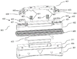
Other embodiments of the present application further optimize the structure of the elastic element 303. Referring to fig. 6, an exploded perspective view of an ultrasound probe 220 in some embodiments of the present application is shown.
As shown in fig. 6, the resilient member 303 may further include a guide post 601. 601 a guide post is disposed between the first base 401 and the second base 402. The spring 403 is sleeved on the periphery of the guide post 601.
Such a configuration can guide the spring 403 during compression and extension, and avoid the spring from twisting or displacing to cause failure. The arrangement of the guide posts 601 may be various. For example, it may comprise a rod-like structure and a sleeve-like structure arranged one above the other. The rod-like structure and the sleeve structure are disposed on opposite faces of the first base 401 and the second base 402, respectively, as shown in fig. 6, and are sized to match, i.e., the sleeve inner diameter is slightly larger than the outer diameter of the rod-like structure, thereby achieving guidance.
The ultrasonic probe 220 can perform linear motion in the horizontal direction under the driving of the driving device in the scanning assembly, and the ultrasonic transducer 301 of the ultrasonic probe 220 also performs linear motion in the horizontal direction. The linear motion ultrasonic transducer 301 performs tomographic scanning of a tissue to be imaged, such as a breast, in the vertical direction, and a large number of two-dimensional sectional ultrasound images of the tissue to be imaged in the vertical direction are obtained. Due to the above-mentioned linear motion, the imaging planes of these two-dimensional images are parallel to each other, and thus a three-dimensional ultrasound image can be obtained by synthesis.
The inventors have found that if there is a wobble of the ultrasound transducer 301 in the direction of motion, the two-dimensional images obtained by tomography will no longer be parallel. Thus, the three-dimensional ultrasound image obtained by synthesis is inevitably affected. In particular, the retractable ultrasound probe is more susceptible to oscillation during movement. In this regard, the inventors have made improvements.
With continued reference to fig. 6, optionally, the resilient element 303 may further include a slide assembly 602 and a link 603. The slide rail assembly 602 includes a guide rail 621 and a slider 622 slidably connected to each other. The sliding rail assembly 602 is disposed at two ends of the second base 402. Further, the connecting rods 603 are disposed at both ends of the first base 401. The link 603 is rotatably connected to the first base 401 and the slider 622.
The above arrangement has various advantages. On one hand, due to the tight fit between the guide rail 621 and the slider 622, the ultrasonic transducer 301 does not swing in the horizontal moving direction during the horizontal movement under driving, so that the imaging quality is not affected. This is of great importance for an ultrasound probe which is itself movable. On the other hand, the slide rail assembly 602 including the guide rail 621 and the slider 622 and the connecting rod 603 can also play a role of limiting the extension and contraction of the ultrasonic transducer 301 in the vertical direction as a whole in cooperation. The connection between the slide rail assembly 602 and the connecting rod 603 ensures that the first base 401 and the second base 402 cannot be unhooked during the up-and-down movement, i.e., the ultrasonic transducer 301 is limited in the extended state. And when the spring 403 is compressed to a certain extent, the slide rail assembly 602 and the connecting rod 603 reach the limit of sliding due to angular rotation and the like, that is, the ultrasonic transducer 301 is limited in the compressed state.
Further, in some embodiments, the connecting rod 603 may be configured in two at each of both ends of the first base 401. The two connecting rods 603 at each end of the first base 401 are rotatably connected to the slider 622 through a bottom plate 604.
Such an arrangement makes the rotational connection of the link 603 more stable. And the arrangement mode of the bottom plate 604 is increased, the assembly of the sliding rail assembly 602 and the connecting rod 603 is more convenient, and during the assembly, the sliding block 622 can be sleeved on the guide rail 621 from the end part of the guide rail 621, so that the bottom plate 604 is aligned with the sliding block 622 for installation. The manner of mounting may be varied, for example, mounting may be by screws. And will not be described in detail herein.
From the above, the above-mentioned solution disclosed in this application enables the ultrasonic probe to have the advantages of compact structure and preventing the probe from swinging in the moving direction while ensuring the vertical telescopic. Further, the inventors have also found that the waterproof performance of the retractable ultrasound probe is also a challenge. The ultrasonic transducer needs to use a coupling agent in the using process, and needs to be disinfected by liquid such as alcohol after the use. A movable probe means that there is a larger gap between the movable parts.
To address the above issues, the present application improves in some embodiments. In some embodiments, the ultrasound probe 220 of the present application may further comprise an elastomeric seal 605. As shown in fig. 4 and 6, the elastic sealing ring 605 includes a corrugated elastic material. The elastic sealing ring 605 is sleeved on the top 311 of the ultrasonic transducer 301 to fill a gap between the top 311 of the ultrasonic transducer 301 and the sidewall 322 of the housing 302.
The corrugated elastomeric seal 605 is such that it can be compressed. On one hand, it can be extended and retracted along with the up and down extension and retraction of the ultrasonic transducer 301, and no damage occurs. On the other hand, the sealing device can achieve a good sealing effect on a gap between the ultrasonic transducer 301 and the housing 302, and prevent liquid from corroding the elastic element 303 and other electrical elements in the housing, such as the PCB 606. The elastic seal 605 may be made of any material, for example, a polymer material such as rubber or latex.
In some embodiments, the top 311 of the ultrasonic transducer 301 and the sidewall 322 of the housing 302 are respectively provided with a card slot. The upper and lower openings of the elastic sealing ring 605 are clamped with the clamping grooves. Specifically, fig. 4 and fig. 6 may be collectively referred to. A card slot 404 may be provided in a side wall 322 of the housing 302, such as at the bottom of the side wall 322. Accordingly, the top 311 of the ultrasound transducer 301 may be provided with another card slot 606. The upper and lower openings of the elastic sealing ring 605 are engaged with the slots, for example, the upper and lower openings may be turned inward, so that the elastic sealing ring can be engaged with the slots.
With such an arrangement, it is possible to ensure that the elastic seal ring 605 does not displace or fall off during the movement of the ultrasonic transducer 301, thereby preventing the failure of the sealing state.
Some embodiments of the present application also provide a scanning assembly 108. As shown in fig. 7, a perspective view of the scanning assembly 108 in some embodiments of the present application is shown.
The scanning assembly 108 may include a frame 801. The frame 801 includes a bottom opening 811. The scanning assembly further comprises an ultrasound probe 220 as described in any of the embodiments above, said ultrasound probe 220 being connected within said frame interior 801. The scanning assembly 108 also includes a membrane assembly 118. The diaphragm assembly 118 is removably coupled to the bottom opening 811.
As can be seen from fig. 7, the overall structure of the scanning assembly 108 is very compact, while any of the above embodiments of the present application describe the structure of the ultrasound probe 220, which does not occupy too much volume and can be easily assembled in the frame of the scanning assembly 108 for ultrasound scanning. Since the ultrasonic probe 220 is configured to be vertically stretchable during scanning, it can undulate in accordance with the shape of the surface to be scanned during scanning in the horizontal direction. In this way, on the one hand, the comfort level of the user to be scanned can be improved, and on the other hand, the imaging quality can also be improved since the ultrasound probe 220 does not cause excessive squeezing of the body. It is understood that the horizontal direction and the up-down direction (or the vertical direction) referred to herein respectively refer to a direction in which the ultrasonic probe 220 is driven to move when performing a scanning and a direction in which the transducer of the ultrasonic probe 220 is extended and contracted.
Further, membrane module 118 includes outer frame 821 and membrane 822. The membrane 822 is disposed within the outer frame 821. The outer frame 821 is detachably connected to the bottom opening 811.
The membrane assembly 118 is capable of mating with the ultrasonic probe 220. The membrane 822 of the membrane assembly 118 can function to compress and immobilize the tissue to be scanned, thereby facilitating smooth motion and high quality imaging of the ultrasound probe 220 on the surface of the tissue to be scanned. It is understood that during ultrasound imaging, one surface of the membrane 822 can be in contact with the ultrasound transducer of the ultrasound probe 220 and the other surface can be in contact with the tissue to be scanned. In the presence of the coupling agent, the acoustic signal has less attenuation through the membrane 822.
In addition to the above-described structure, the scanning assembly 108 of the present application may include other components. These components are explained in detail below. It should be noted that the following components are not necessary as alternative examples.
With continued reference to FIG. 7, the scanning assembly 108 also includes two handles 803 disposed on the frame 801. The two handles 803 oppose each other across a transverse axis of the scanning assembly 108, which is centered on and defined relative to the adjustable arm 106. The opening shape of the frame 801 may be rectangular. In another example, the frame 801 may be another shape, such as a square with a square opening. In addition, the frame 801 has a thickness defined between the inner and outer peripheries of the frame 801.
Two handles 803 are used to move the scanning assembly 108 in space and position the scanning assembly 108 on tissue (e.g., on a patient). In alternative embodiments, the scanning assembly 108 may not include the handle 803. In an example, the handle 803 may be integrally formed with the frame 801. In another example, the handle 803 and the frame 801 may be formed separately.
As shown in fig. 7, the scanning assembly 108 is connected to the adjustable arm 106 by a ball joint 112 (e.g., a ball and socket connector). Specifically, the top dome portion of the frame 801 is connected to the ball joint 112. The top of the frame 801 includes a recess that forms a socket into which the ball of the ball joint 112 fits. The ball joint 112 may move in multiple directions. For example, the ball joint 112 provides rotational movement of the scanning assembly relative to the adjustable arm 106. The ball joint 112 includes a locking mechanism for locking the ball joint 112 in place and thereby holding the scanning assembly 108 stationary relative to the adjustable arm 106. Further, the ball joint 112 may also be configured to only rotate without moving in multiple directions such as swinging.
In addition, as shown in fig. 7, a button for controlling the scanning and adjusting the scanning assembly 108 is further provided on the handle 803. Specifically, the above buttons may include a first weight adjustment button 804 and a second weight adjustment button 805. The first weight adjustment button 804 may reduce the load applied to the scan assembly 108 from the adjustable arm 106. The second weight adjustment button 805 may increase the load applied to the scanning assembly 108 from the adjustable arm 106. The increase or decrease may be controlled based on the magnitude of the downforce displacement of the adjustable ratio 106 with respect to the scanning assembly 108. Increasing the load applied to the scanning assembly 108 may increase the amount of pressure and compression applied to the tissue on which the scanning assembly 108 is placed. In addition, increasing the load applied to the scanning assembly increases the effective weight of the scanning assembly on the tissue to be scanned. In one example, increasing the load may compress tissue of the patient, such as the breast. In this manner, varying amounts of pressure (e.g., load) may be applied in concert with the scanning assembly 108 during scanning to obtain high quality images with the ultrasound probe 220.
Prior to the scanning procedure, a user (e.g., an ultrasound technician or physician) may position the scanning assembly 108 on a patient or tissue. Once the scan assembly 108 placement is complete, the user may adjust the pressure of the scan assembly 108 on the patient (e.g., adjust the amount of compression) by using the first weight adjustment button 804 and/or the second weight adjustment button 805. The user may then initiate the scanning process by additional controls on the handle 803, such as a button of another handle.
Automatic scanning of the ultrasound probe may be accomplished by relying on a drive means inside the frame 801 of the scanning assembly 108. Referring to fig. 8, a schematic diagram of the connection relationship between the driving device 230 and the ultrasound probe 220 in some embodiments of the present application is shown. The top structure of the frame 801 of the scanning assembly 108 is removed from the figure.
Wherein the driving device 230 is disposed in the frame 801. The driving device is connected to the sidewall 322 of the housing 302 of the ultrasonic probe 220 to drive the ultrasonic probe 220 to move. In this manner, automatic scanning of the tissue to be scanned by the ultrasound probe 220 may be achieved without the need for the scanner to hold and move the probe.
In some embodiments, the drive device 230 includes a motor 861 and a lead screw 862. The lead screw 862 is horizontally disposed within the frame. The motor 861 is coupled to the side wall 322 of the housing 302. The motor is movably connected with the screw rod to drive the ultrasonic probe to move in the horizontal direction.
The lead screw 862 may be disposed in the frame 801 in any manner, and for example, both ends thereof may be fixedly connected to both sidewalls of the frame 801. The connection of the motor 861 to the housing of the ultrasound probe 220 may likewise be arbitrary. For example, motor 861 may be fixedly coupled to sidewall 322 by a screw arrangement. The motor 861 is movably connected with the lead screw 862 so as to drive the ultrasonic probe 220 to move.
The motor 861 drives the ultrasonic probe 220 to reciprocate along the screw rod direction by rotating the internal output shaft in different directions (for example, clockwise or counterclockwise), or driving a gear through the output shaft to be movably connected with the screw rod 862, so as to automatically perform ultrasonic scanning. It should be noted that other movement patterns are also possible, such as rotating the ultrasound probe 220 around a certain center. Although the internal structure of the motor 861 is not directly shown in fig. 8, it should be understood by those skilled in the art that any means of satisfying the movable connection between the motor 861 and the lead screw 862 is allowed.
In addition, in some embodiments of the present application, an ultrasound imaging apparatus is also disclosed, which includes the scanning assembly described in any of the above embodiments.
In some embodiments, the ultrasound imaging apparatus may include an adjustable arm and a host as shown in fig. 1. The scanning component is connected with one end of the adjustable arm; the host is connected with the other end of the adjustable arm.
The above specific embodiments are provided so that this disclosure will be thorough and complete, and the present application is not limited to these specific embodiments. It will be understood by those skilled in the art that various changes, substitutions and alterations can be made herein without departing from the spirit and scope of the application.
Claims (13)
1. An ultrasound probe, comprising:
an ultrasonic transducer for transmitting/receiving an ultrasonic signal;
the ultrasonic transducer comprises a shell, a plurality of ultrasonic transducers and a plurality of ultrasonic sensors, wherein the shell comprises a cavity surrounded by a top plate and a side wall and an opening positioned below the cavity, and the top of each ultrasonic transducer is accommodated in the cavity through the opening; and
an elastic element housed within the cavity, the elastic element connecting a top of the ultrasonic transducer and the top plate of the housing, the elastic element configured to provide an elastic force to the ultrasonic transducer to enable a portion of the ultrasonic transducer to contract and rebound within the cavity.
2. The ultrasound probe of claim 1, wherein the elastic element comprises:
a first base connected to the top plate of the housing;
a second base connected to a top of the ultrasonic transducer; and
a spring disposed between the first base and the second base to enable elastic connection of the first base and the second base.
3. The ultrasound probe of claim 2, wherein the elastic element further comprises:
the guide post, the guide post set up in first base with between the second base, the spring housing is located the periphery of guide post.
4. The ultrasound probe of claim 2, wherein the elastic element further comprises:
the sliding rail assembly comprises a guide rail and a sliding block which are connected in a sliding manner, and the sliding rail assembly is arranged at two ends of the second base;
the connecting rods are arranged at two ends of the first base and are rotatably connected with the first base and the sliding block.
5. The ultrasound probe of claim 4, wherein:
the number of the links at each of both ends of the first base is two, and the two links at each of the ends of the first base are rotatably connected to the slider through a bottom plate.
6. The ultrasound probe of claim 1, further comprising:
the elastic sealing ring comprises a corrugated elastic material, and is sleeved on the top of the ultrasonic transducer to fill a gap between the top of the ultrasonic transducer and the side wall of the shell.
7. The ultrasound probe of claim 6, wherein:
the top of the ultrasonic transducer and the side wall of the shell are respectively provided with a clamping groove, and the upper opening and the lower opening of the elastic sealing ring are clamped with the clamping grooves.
8. A scanning assembly, comprising:
a frame comprising a bottom opening;
an ultrasound probe according to any preceding claim, connected within the frame; and
and the membrane assembly is detachably connected with the bottom opening.
9. The scanning assembly of claim 8, further comprising:
the driving device is arranged in the frame and is connected with the side wall of the shell of the ultrasonic probe so as to drive the ultrasonic probe to move.
10. The scanning assembly of claim 9, wherein:
the driving device comprises a motor and a screw rod, the screw rod is horizontally arranged in the frame, the motor is connected with the side wall of the shell, and the motor is movably connected with the screw rod to drive the ultrasonic probe to move in the horizontal direction.
11. The scanning assembly of claim 8, wherein:
the membrane assembly comprises an outer frame and a membrane, the membrane is arranged in the outer frame, and the outer frame is detachably connected with the bottom opening.
12. An ultrasound imaging apparatus comprising a scanning assembly as claimed in any one of claims 8-11.
13. The ultrasound imaging apparatus according to claim 12, further comprising:
an adjustable arm, the scanning assembly being connected to one end of the adjustable arm; and
the host is connected with the other end of the adjustable arm.
Priority Applications (3)
| Application Number | Priority Date | Filing Date | Title |
|---|---|---|---|
| CN202111016870.4A CN115721334A (en) | 2021-08-31 | 2021-08-31 | Ultrasonic probe, scanning assembly and ultrasonic imaging device |
| JP2022123655A JP7434453B2 (en) | 2021-08-31 | 2022-08-03 | Ultrasonic probes, scanning assemblies, and ultrasound imagers |
| US17/893,819 US20230061594A1 (en) | 2021-08-31 | 2022-08-23 | Ultrasonic probe, scanning assembly and ultrasonic imaging device |
Applications Claiming Priority (1)
| Application Number | Priority Date | Filing Date | Title |
|---|---|---|---|
| CN202111016870.4A CN115721334A (en) | 2021-08-31 | 2021-08-31 | Ultrasonic probe, scanning assembly and ultrasonic imaging device |
Publications (1)
| Publication Number | Publication Date |
|---|---|
| CN115721334A true CN115721334A (en) | 2023-03-03 |
Family
ID=85288532
Family Applications (1)
| Application Number | Title | Priority Date | Filing Date |
|---|---|---|---|
| CN202111016870.4A Pending CN115721334A (en) | 2021-08-31 | 2021-08-31 | Ultrasonic probe, scanning assembly and ultrasonic imaging device |
Country Status (3)
| Country | Link |
|---|---|
| US (1) | US20230061594A1 (en) |
| JP (1) | JP7434453B2 (en) |
| CN (1) | CN115721334A (en) |
Families Citing this family (1)
| Publication number | Priority date | Publication date | Assignee | Title |
|---|---|---|---|---|
| KR102551704B1 (en) * | 2022-11-18 | 2023-07-05 | (주)쉬엔비 | Handpiece that can adjust the focusing depth of high-intensity focused ultrasound |
Family Cites Families (12)
| Publication number | Priority date | Publication date | Assignee | Title |
|---|---|---|---|---|
| DE3476132D1 (en) * | 1983-06-23 | 1989-02-16 | Matsushita Electric Ind Co Ltd | Ultrasonic probe having dual-motion transducer |
| JPH04183453A (en) * | 1990-11-20 | 1992-06-30 | Terumo Corp | Ultrasonic diagnostic device |
| US7299806B2 (en) * | 2003-11-25 | 2007-11-27 | General Electric Company | Compliant probe interface assembly |
| US20080269613A1 (en) * | 2004-04-26 | 2008-10-30 | Summers Douglas G | Versatile Breast Ultrasound Scanning |
| US20140121520A1 (en) * | 2006-05-02 | 2014-05-01 | U-Systems, Inc. | Medical ultrasound scanning with control over pressure/force exerted by an ultrasound probe and/or a compression/scanning assembly |
| WO2013171671A1 (en) * | 2012-05-15 | 2013-11-21 | Koninklijke Philips N.V. | Mechanically scanned three-dimensional ultrasound imaging adapted to the contours of a body |
| US9615815B2 (en) * | 2012-09-28 | 2017-04-11 | Clemson University Research Foundation | Devices that cooperate with ultrasound probes for muscoskeletal evaluations and related systems and methods |
| KR101335476B1 (en) * | 2013-02-25 | 2013-12-11 | 주식회사 코러스트 | Line-focus type ultrasound transducer and high intensity focused ultrasound generating apparatus including the same |
| US9597056B2 (en) * | 2013-09-30 | 2017-03-21 | General Electric Company | Method and systems for weight adjustment of an automated breast ultrasound system |
| US9808224B2 (en) * | 2013-09-30 | 2017-11-07 | General Electric Company | Method and systems for a removable transducer with memory of an automated breast ultrasound system |
| CN105877780B (en) * | 2015-08-25 | 2019-05-31 | 上海深博医疗器械有限公司 | Fully-automatic ultrasonic scanner and scanning detection method |
| CN205514668U (en) * | 2016-02-04 | 2016-08-31 | 深圳迈瑞生物医疗电子股份有限公司 | Ultrasonic scanning probe and ultrasonic imaging system |
-
2021
- 2021-08-31 CN CN202111016870.4A patent/CN115721334A/en active Pending
-
2022
- 2022-08-03 JP JP2022123655A patent/JP7434453B2/en active Active
- 2022-08-23 US US17/893,819 patent/US20230061594A1/en active Pending
Also Published As
| Publication number | Publication date |
|---|---|
| JP2023035876A (en) | 2023-03-13 |
| US20230061594A1 (en) | 2023-03-02 |
| JP7434453B2 (en) | 2024-02-20 |
Similar Documents
| Publication | Publication Date | Title |
|---|---|---|
| US9597056B2 (en) | Method and systems for weight adjustment of an automated breast ultrasound system | |
| US10561394B2 (en) | Ultrasound scanning and ultrasound-assisted biopsy | |
| US20140121520A1 (en) | Medical ultrasound scanning with control over pressure/force exerted by an ultrasound probe and/or a compression/scanning assembly | |
| JP4825197B2 (en) | Various chest ultrasound operations | |
| AU2014409333B2 (en) | Ultrasonic cartridge and ultrasonic treatment head using same | |
| WO2015099849A1 (en) | Medical ultrasound scanning with control over pressure/force exerted by an ultrasound probe and/or a compression/scanning assembly | |
| US11241215B2 (en) | Membrane for breast ultrasound systems | |
| KR102067070B1 (en) | Ultrasonic probe cradled device of multi versatile | |
| US7299806B2 (en) | Compliant probe interface assembly | |
| CN115721334A (en) | Ultrasonic probe, scanning assembly and ultrasonic imaging device | |
| US9808224B2 (en) | Method and systems for a removable transducer with memory of an automated breast ultrasound system | |
| US11710229B2 (en) | Methods and systems for shear wave elastography | |
| CN108030513B (en) | External scanning three-dimensional imaging device for ultrasonic CT | |
| CN114431892B (en) | Ultrasonic imaging system and ultrasonic imaging method | |
| US20220096051A1 (en) | Scanning assembly for ultrasonic imaging device and ultrasonic imaging device | |
| US20190321004A1 (en) | Ultrasound Imaging Probe | |
| CN219422850U (en) | Conformal linear array ultrasonic probe | |
| JP4555674B2 (en) | Measuring unit and bone diagnostic apparatus provided with the same | |
| CN113827276B (en) | Ultrasonic imaging system and imaging method thereof | |
| CN118557218A (en) | Scanning assembly and ultrasonic imaging device |
Legal Events
| Date | Code | Title | Description |
|---|---|---|---|
| PB01 | Publication | ||
| PB01 | Publication | ||
| SE01 | Entry into force of request for substantive examination | ||
| SE01 | Entry into force of request for substantive examination |