CN115715355A - Fluid system comprising duplex stainless steel - Google Patents
Fluid system comprising duplex stainless steel Download PDFInfo
- Publication number
- CN115715355A CN115715355A CN202180029919.1A CN202180029919A CN115715355A CN 115715355 A CN115715355 A CN 115715355A CN 202180029919 A CN202180029919 A CN 202180029919A CN 115715355 A CN115715355 A CN 115715355A
- Authority
- CN
- China
- Prior art keywords
- fluid
- coupling body
- duplex stainless
- stainless steel
- ring
- Prior art date
- Legal status (The legal status is an assumption and is not a legal conclusion. Google has not performed a legal analysis and makes no representation as to the accuracy of the status listed.)
- Pending
Links
Images


Classifications
-
- F—MECHANICAL ENGINEERING; LIGHTING; HEATING; WEAPONS; BLASTING
- F16—ENGINEERING ELEMENTS AND UNITS; GENERAL MEASURES FOR PRODUCING AND MAINTAINING EFFECTIVE FUNCTIONING OF MACHINES OR INSTALLATIONS; THERMAL INSULATION IN GENERAL
- F16L—PIPES; JOINTS OR FITTINGS FOR PIPES; SUPPORTS FOR PIPES, CABLES OR PROTECTIVE TUBING; MEANS FOR THERMAL INSULATION IN GENERAL
- F16L37/00—Couplings of the quick-acting type
- F16L37/08—Couplings of the quick-acting type in which the connection between abutting or axially overlapping ends is maintained by locking members
- F16L37/12—Couplings of the quick-acting type in which the connection between abutting or axially overlapping ends is maintained by locking members using hooks, pawls, or other movable or insertable locking members
- F16L37/138—Couplings of the quick-acting type in which the connection between abutting or axially overlapping ends is maintained by locking members using hooks, pawls, or other movable or insertable locking members using an axially movable sleeve
-
- F—MECHANICAL ENGINEERING; LIGHTING; HEATING; WEAPONS; BLASTING
- F16—ENGINEERING ELEMENTS AND UNITS; GENERAL MEASURES FOR PRODUCING AND MAINTAINING EFFECTIVE FUNCTIONING OF MACHINES OR INSTALLATIONS; THERMAL INSULATION IN GENERAL
- F16L—PIPES; JOINTS OR FITTINGS FOR PIPES; SUPPORTS FOR PIPES, CABLES OR PROTECTIVE TUBING; MEANS FOR THERMAL INSULATION IN GENERAL
- F16L19/00—Joints in which sealing surfaces are pressed together by means of a member, e.g. a swivel nut, screwed on, or into, one of the joint parts
- F16L19/08—Joints in which sealing surfaces are pressed together by means of a member, e.g. a swivel nut, screwed on, or into, one of the joint parts with metal rings which bite into the wall of the pipe
- F16L19/10—Joints in which sealing surfaces are pressed together by means of a member, e.g. a swivel nut, screwed on, or into, one of the joint parts with metal rings which bite into the wall of the pipe the profile of the ring being altered
-
- C—CHEMISTRY; METALLURGY
- C22—METALLURGY; FERROUS OR NON-FERROUS ALLOYS; TREATMENT OF ALLOYS OR NON-FERROUS METALS
- C22C—ALLOYS
- C22C38/00—Ferrous alloys, e.g. steel alloys
- C22C38/18—Ferrous alloys, e.g. steel alloys containing chromium
- C22C38/40—Ferrous alloys, e.g. steel alloys containing chromium with nickel
- C22C38/44—Ferrous alloys, e.g. steel alloys containing chromium with nickel with molybdenum or tungsten
-
- F—MECHANICAL ENGINEERING; LIGHTING; HEATING; WEAPONS; BLASTING
- F16—ENGINEERING ELEMENTS AND UNITS; GENERAL MEASURES FOR PRODUCING AND MAINTAINING EFFECTIVE FUNCTIONING OF MACHINES OR INSTALLATIONS; THERMAL INSULATION IN GENERAL
- F16L—PIPES; JOINTS OR FITTINGS FOR PIPES; SUPPORTS FOR PIPES, CABLES OR PROTECTIVE TUBING; MEANS FOR THERMAL INSULATION IN GENERAL
- F16L13/00—Non-disconnectable pipe joints, e.g. soldered, adhesive, or caulked joints
- F16L13/007—Non-disconnectable pipe joints, e.g. soldered, adhesive, or caulked joints specially adapted for joining pipes of dissimilar materials
-
- F—MECHANICAL ENGINEERING; LIGHTING; HEATING; WEAPONS; BLASTING
- F16—ENGINEERING ELEMENTS AND UNITS; GENERAL MEASURES FOR PRODUCING AND MAINTAINING EFFECTIVE FUNCTIONING OF MACHINES OR INSTALLATIONS; THERMAL INSULATION IN GENERAL
- F16L—PIPES; JOINTS OR FITTINGS FOR PIPES; SUPPORTS FOR PIPES, CABLES OR PROTECTIVE TUBING; MEANS FOR THERMAL INSULATION IN GENERAL
- F16L13/00—Non-disconnectable pipe joints, e.g. soldered, adhesive, or caulked joints
- F16L13/14—Non-disconnectable pipe joints, e.g. soldered, adhesive, or caulked joints made by plastically deforming the material of the pipe, e.g. by flanging, rolling
- F16L13/146—Non-disconnectable pipe joints, e.g. soldered, adhesive, or caulked joints made by plastically deforming the material of the pipe, e.g. by flanging, rolling by an axially moveable sleeve
-
- F—MECHANICAL ENGINEERING; LIGHTING; HEATING; WEAPONS; BLASTING
- F16—ENGINEERING ELEMENTS AND UNITS; GENERAL MEASURES FOR PRODUCING AND MAINTAINING EFFECTIVE FUNCTIONING OF MACHINES OR INSTALLATIONS; THERMAL INSULATION IN GENERAL
- F16L—PIPES; JOINTS OR FITTINGS FOR PIPES; SUPPORTS FOR PIPES, CABLES OR PROTECTIVE TUBING; MEANS FOR THERMAL INSULATION IN GENERAL
- F16L13/00—Non-disconnectable pipe joints, e.g. soldered, adhesive, or caulked joints
- F16L13/14—Non-disconnectable pipe joints, e.g. soldered, adhesive, or caulked joints made by plastically deforming the material of the pipe, e.g. by flanging, rolling
- F16L13/16—Non-disconnectable pipe joints, e.g. soldered, adhesive, or caulked joints made by plastically deforming the material of the pipe, e.g. by flanging, rolling the pipe joint consisting of overlapping extremities having mutually co-operating collars
- F16L13/165—Non-disconnectable pipe joints, e.g. soldered, adhesive, or caulked joints made by plastically deforming the material of the pipe, e.g. by flanging, rolling the pipe joint consisting of overlapping extremities having mutually co-operating collars the pipe or collar being deformed by an axially movable sleeve
-
- C—CHEMISTRY; METALLURGY
- C21—METALLURGY OF IRON
- C21D—MODIFYING THE PHYSICAL STRUCTURE OF FERROUS METALS; GENERAL DEVICES FOR HEAT TREATMENT OF FERROUS OR NON-FERROUS METALS OR ALLOYS; MAKING METAL MALLEABLE, e.g. BY DECARBURISATION OR TEMPERING
- C21D2211/00—Microstructure comprising significant phases
- C21D2211/001—Austenite
-
- C—CHEMISTRY; METALLURGY
- C21—METALLURGY OF IRON
- C21D—MODIFYING THE PHYSICAL STRUCTURE OF FERROUS METALS; GENERAL DEVICES FOR HEAT TREATMENT OF FERROUS OR NON-FERROUS METALS OR ALLOYS; MAKING METAL MALLEABLE, e.g. BY DECARBURISATION OR TEMPERING
- C21D2211/00—Microstructure comprising significant phases
- C21D2211/005—Ferrite
Landscapes
- Engineering & Computer Science (AREA)
- General Engineering & Computer Science (AREA)
- Mechanical Engineering (AREA)
- Chemical & Material Sciences (AREA)
- Materials Engineering (AREA)
- Metallurgy (AREA)
- Organic Chemistry (AREA)
- Earth Drilling (AREA)
- Joints With Pressure Members (AREA)
- Joints With Sleeves (AREA)
- Gasket Seals (AREA)
- Quick-Acting Or Multi-Walled Pipe Joints (AREA)
- Cleaning And De-Greasing Of Metallic Materials By Chemical Methods (AREA)
Abstract
流体系统包含用于机械地附接到流体元件的流体接头。流体接头包含耦接主体,该耦接主体具有内表面和密封部分,该内表面限定孔,该孔用于在孔中接收流体元件,密封部分形成在内表面上,用于接合流体元件。流体接头还包含环,该环被配置为装配在耦接主体的至少一个端部上。在环经由力被安装在耦接主体上的情况下,其中,流体元件被接收在孔中,环向耦接主体施加足以引起耦接主体的永久变形的压缩力,使得密封部分的齿咬合到流体元件中,从而由此将流体元件以不泄漏的方式附接到耦接主体。此外,流体元件、耦接主体和环中的至少一个包含双相不锈钢。
The fluid system includes a fluid connector for mechanical attachment to the fluid element. The fluid fitting includes a coupling body having an inner surface defining a bore for receiving a fluid element therein and a sealing portion formed on the inner surface for engaging the fluid element. The fluid joint also includes a ring configured to fit over at least one end of the coupling body. Where the ring is force mounted on the coupling body, wherein the fluid element is received in the bore, the ring applies a compressive force to the coupling body sufficient to cause permanent deformation of the coupling body such that the teeth of the sealing portion snap into the In the fluid element, thereby attaching the fluid element to the coupling body in a leak-tight manner. Additionally, at least one of the fluid element, the coupling body, and the ring comprises duplex stainless steel.
Description
相关申请的交叉引用Cross References to Related Applications
本申请要求于2020年4月23日提交的序列号为63/014,392的美国临时申请的权益,该美国临时申请的内容通过引用并入。This application claims the benefit of U.S. Provisional Application Serial No. 63/014,392, filed April 23, 2020, the contents of which are incorporated by reference.
技术领域technical field
本公开内容总体上涉及一种流体系统,该流体系统包含用于机械地附接到流体元件的流体接头,特别地,其中,流体接头和流体元件中的至少一个包含双相不锈钢材料。The present disclosure generally relates to a fluid system including a fluid fitting for mechanically attaching to a fluid element, in particular wherein at least one of the fluid fitting and the fluid element comprises a duplex stainless steel material.
背景技术Background technique
在当前的实践中,管道和接头通常通过焊接附接在一起。然而,这种焊接技术抑制了用不能被焊接在一起的材料或者用需要高水平的技能才能合适地焊接的材料制造管道和接头的能力。In current practice, pipes and fittings are usually attached together by welding. However, this welding technique inhibits the ability to fabricate pipes and fittings from materials that cannot be welded together or that require a high level of skill to weld properly.
例如,与标准奥氏体不锈钢相比,双相不锈钢以它们优异的耐腐蚀性、高强度、足够的延展性、良好的再成型性和成本效益而著称。这些改进的性能通常归因于双相不锈钢的奥氏体和铁素体的双相微观结构。然而,与其他合金相比,双相不锈钢在焊接温度下的稳定性较差。具体地,焊接可能破坏钢的微观结构,最终向内侧降低耐腐蚀性和韧性。For example, duplex stainless steels are known for their superior corrosion resistance, high strength, adequate ductility, good re-formability, and cost-effectiveness compared to standard austenitic stainless steels. These improved properties are generally attributed to the duplex microstructure of austenite and ferrite in duplex stainless steels. However, duplex stainless steels are less stable at welding temperatures than other alloys. Specifically, welding can damage the microstructure of the steel, ultimately reducing corrosion resistance and toughness inwardly.
此外,不合适的焊接技术和步骤会对双相不锈钢带来不利的影响,诸如比例不合适的铁素体与奥氏体的比率以及金属间相的形成,这会导致焊接区域中的加速的腐蚀或机械故障。这些影响可能会损害流体接头和管道,特别是在存在诸如硫化氢的腐蚀性的工艺流体或气体的情况下。例如,存在于水中的H2S会以腐蚀、裂开或起泡的形式对钢管路造成损坏。H2S对钢的影响可能导致硫化物应力开裂(SSC)、氢致开裂(HIC)和腐蚀。二氧化碳的存在倾向于增加钢的腐蚀速率。二氧化碳的存在还可能增加钢对SSC和HIC二者的敏感性。In addition, improper welding techniques and procedures can have adverse effects on duplex stainless steels, such as improperly proportioned ferrite to austenite ratios and the formation of intermetallic phases, which can lead to accelerated corrosion or mechanical failure. These effects can damage fluid connections and piping, especially in the presence of corrosive process fluids or gases such as hydrogen sulfide. For example, H 2 S present in water can cause damage to steel piping in the form of corrosion, cracking or foaming. The effect of H2S on steel can lead to sulfide stress cracking (SSC), hydrogen induced cracking (HIC) and corrosion. The presence of carbon dioxide tends to increase the corrosion rate of steel. The presence of carbon dioxide may also increase the susceptibility of steel to both SSC and HIC.
因此,在焊接包括双相不锈钢的管道和接头的情况下,需要高水平的技能和控制,并且必须采取关键的步骤来确保钢在焊接区域中保持足够的耐腐蚀性和机械性能。在需要最大效果的情况下,诸如在腐蚀服务应用中,选择合适的基材和焊接填充金属将不能保证成功。在焊接双相不锈钢的情况下,需要特别注意焊接工艺、焊工技术、焊道形状、预热温度/道间温度、每个焊道基部的热输入以及腐蚀样品制备,以实现令人满意的结果。Therefore, in the case of welding pipe and joints comprising duplex stainless steels, a high level of skill and control is required, and critical steps must be taken to ensure that the steel retains adequate corrosion resistance and mechanical properties in the weld zone. Where maximum effect is required, such as in corrosion service applications, selection of the proper base material and weld filler metal will not guarantee success. In the case of welding duplex stainless steels, special attention needs to be paid to the welding process, welder technique, bead shape, preheat/interpass temperature, heat input at the base of each bead, and corrosion sample preparation to achieve satisfactory results .
发明内容Contents of the invention
以下呈现了本发明的示例实施例的简化概要。该概要并非旨在表明本发明的关键元件或描述本发明的范围。A simplified summary of an example embodiment of the invention is presented below. This summary is not intended to identify key elements of the invention or to delineate the scope of the invention.
根据第一方面,用于机械地附接到流体元件的流体接头包含耦接主体,该耦接主体限定孔,该孔用于在孔中接收所述流体元件,耦接主体包含套筒部分和齿,该齿从套筒部分径向地向内延伸,用于接合所述流体元件。流体接头还包含环,该环被配置为装配在耦接主体的至少一个端部上,用于将耦接主体机械地附接到所述流体元件。在环经由力被安装在耦接主体的至少一个端部上的情况下,其中,流体元件被接收在孔中,环向耦接主体施加足以引起耦接主体的永久变形的压缩力,使得耦接主体的齿咬合到所述流体元件中,从而由此将耦接主体以不泄漏的方式附接到所述流体元件。此外,耦接主体和环中的至少一个包含双相不锈钢。According to a first aspect, a fluid connector for mechanically attaching to a fluid element comprises a coupling body defining a bore for receiving said fluid element therein, the coupling body comprising a sleeve portion and Teeth extending radially inwardly from the sleeve portion for engaging the fluid element. The fluid joint also includes a ring configured to fit over at least one end of the coupling body for mechanically attaching the coupling body to the fluid element. Where the ring is force mounted on at least one end of the coupling body, wherein the fluid element is received in the bore, the ring applies a compressive force to the coupling body sufficient to cause permanent deformation of the coupling body such that the coupling The teeth of the coupling body snap into the fluid element, thereby attaching the coupling body to the fluid element in a leak-tight manner. Additionally, at least one of the coupling body and the ring comprises duplex stainless steel.
在第一方面的一个示例中,耦接主体和环都包含双相不锈钢。In one example of the first aspect, both the coupling body and the ring comprise duplex stainless steel.
在第一方面的另一示例中,耦接主体和驱动环中的一者包含双相不锈钢,并且耦接主体和驱动环中的另一者不包含双相不锈钢。In another example of the first aspect, one of the coupling body and the drive ring includes duplex stainless steel, and the other of the coupling body and drive ring does not include duplex stainless steel.
在第一方面的又一示例中,双相不锈钢包含的奥氏体与铁素体的比率为约35%至约65%。In yet another example of the first aspect, the duplex stainless steel comprises a ratio of austenite to ferrite of about 35% to about 65%.
在第一方面的再一示例中,双相不锈钢包含最少约25%质量的铬。In a further example of the first aspect, the duplex stainless steel includes a minimum of about 25% by mass chromium.
在第一方面的另一示例中,双相不锈钢包含最少约2%质量的钼。In another example of the first aspect, the duplex stainless steel includes a minimum of about 2% molybdenum by mass.
在第一方面的又一示例中,双相不锈钢包含最少约6.5%质量的镍。In yet another example of the first aspect, the duplex stainless steel includes a minimum of about 6.5% by mass nickel.
在第一方面的再一示例中,双相不锈钢包含约40或更大的PREN(即,耐点蚀当量)。In yet another example of the first aspect, the duplex stainless steel comprises a PREN (ie, Pitting Resistance Equivalent) of about 40 or greater.
在第一方面的另一示例中,齿包含基本上梯形的横截面轮廓。In another example of the first aspect, the tooth comprises a substantially trapezoidal cross-sectional profile.
在第一方面的又一示例中,耦接主体的孔具有限定耦接主体的轴向方向和径向方向的中心轴线。齿包含内侧齿面、外侧齿面和远端面,该远端面在内侧齿面和外侧齿面之间延伸。此外,内侧齿面和外侧齿面倾斜于径向方向延伸。在一个示例中,径向方向与内侧齿面和外侧齿面中的每一个之间的角度是约40度至约60度。在另一示例中,远端面的横截面轮廓是基本上平的。在又一示例中,远端面的横截面轮廓是圆拱形的,具有约0.010”至约0.050”的曲率半径。在再一示例中,远端面的横截面轮廓具有约0.005”至约0.040”的长度。在另一示例中,远端面与内侧齿面和外侧齿面在相应的边缘处相交,每个边缘具有约0.003”至约0.005”的曲率半径。In a further example of the first aspect, the bore of the coupling body has a central axis defining an axial direction and a radial direction of the coupling body. The tooth includes an inner tooth face, an outer tooth face, and a distal face extending between the inner tooth face and the outer tooth face. Furthermore, the inner tooth flank and the outer tooth flank extend obliquely to the radial direction. In one example, the angle between the radial direction and each of the inner and outer flanks is about 40 degrees to about 60 degrees. In another example, the cross-sectional profile of the distal face is substantially flat. In yet another example, the cross-sectional profile of the distal face is rounded with a radius of curvature of about 0.010" to about 0.050". In yet another example, the cross-sectional profile of the distal face has a length of about 0.005" to about 0.040". In another example, the distal face intersects the inner and outer flanks at respective edges, each edge having a radius of curvature of about 0.003" to about 0.005".
在第一方面的再一示例中,耦接主体是单个的、单体式的材料主体,该单个的、单体式的材料主体具有一个或多个应变硬化部分和一个或多个未应变硬化部分。In a further example of the first aspect, the coupling body is a single, unitary body of material having one or more strain hardened portions and one or more non-strain hardened part.
根据第二方面,流体系统包含流体元件和用于机械地附接到流体元件的流体接头。流体接头包含耦接主体,该耦接主体具有内表面和密封部分,该内表面限定孔,该孔用于在孔中接收流体元件,密封部分形成在内表面上,用于接合流体元件。流体接头还包含环,该环被配置为装配在耦接主体的至少一个端部上,用于将耦接主体机械地附接到流体元件。在环经由力被安装在耦接主体的至少一个端部上的情况下,其中,流体元件被接收在孔中,环向耦接主体施加足以引起耦接主体的永久变形的压缩力,使得密封部分的齿咬合到流体元件中,从而由此将流体元件以不泄漏的方式附接到耦接主体。此外,流体元件、耦接主体和环中的至少一个包含双相不锈钢。According to a second aspect, a fluid system comprises a fluid element and a fluid connection for mechanical attachment to the fluid element. The fluid fitting includes a coupling body having an inner surface defining a bore for receiving a fluid element therein and a sealing portion formed on the inner surface for engaging the fluid element. The fluid joint also includes a ring configured to fit over at least one end of the coupling body for mechanically attaching the coupling body to the fluid element. Where the ring is force mounted on at least one end of the coupling body, wherein the fluid element is received in the bore, the ring applies a compressive force to the coupling body sufficient to cause permanent deformation of the coupling body such that the seal Part of the teeth snap into the fluid element, thereby attaching the fluid element to the coupling body in a leak-tight manner. Additionally, at least one of the fluid element, the coupling body, and the ring comprises duplex stainless steel.
在第二方面的一个示例中,流体元件和耦接主体都包含双相不锈钢。In an example of the second aspect, both the fluid element and the coupling body comprise duplex stainless steel.
在第二方面的另一示例中,流体元件和耦接主体中的一者包含双相不锈钢,并且流体元件和耦接主体中的另一者不包含双相不锈钢。In another example of the second aspect, one of the fluid element and the coupling body includes duplex stainless steel, and the other of the fluid element and the coupling body does not include duplex stainless steel.
在第二方面的又一示例中,齿包含基本上梯形的横截面轮廓。In a further example of the second aspect, the tooth comprises a substantially trapezoidal cross-sectional profile.
应当理解,前面的一般描述和下面的详细描述都呈现了示例性的和说明性的实施例。包含所附的附图以提供对所描述的实施例的进一步的理解并且所附的附图被并入且构成该说明书的一部分。附图图示了本发明的各种示例实施例。It is to be understood that both the foregoing general description and the following detailed description present exemplary and explanatory embodiments. The accompanying drawings are included to provide a further understanding of the described embodiments and are incorporated in and constitute a part of this specification. The figures illustrate various example embodiments of the invention.
附图说明Description of drawings
在参考所附的附图阅读下面的描述后,本发明的前述方面和其他方面对于本发明所涉及的本领域的技术人员将变得显而易见的,在附图中:The foregoing and other aspects of the invention will become apparent to those skilled in the art to which the invention pertains after reading the following description with reference to the accompanying drawings in which:
图1是用于机械地附接到流体元件的示例流体接头的横截面图;1 is a cross-sectional view of an example fluid fitting for mechanically attaching to a fluidic element;
图2是处于预安装配置中的接头的详细的横截面图;Figure 2 is a detailed cross-sectional view of the joint in a pre-assembled configuration;
图3是处于安装配置中的接头的另一详细的横截面图;Figure 3 is another detailed cross-sectional view of the joint in the installed configuration;
图4A是在附接到流体接头之前的流体元件的显微图像;Figure 4A is a microscopic image of a fluidic element prior to attachment to a fluidic joint;
图4B是在附接到流体接头之后的流体元件的显微图像;Figure 4B is a microscopic image of a fluidic element after attachment to a fluidic joint;
图5是用于接头的示例齿的详细的横截面图;Figure 5 is a detailed cross-sectional view of an example tooth for a joint;
图6是用于接头的另一示例齿的详细的横截面图;Figure 6 is a detailed cross-sectional view of another example tooth for a joint;
图7A是工件的立体图,该工件可以被加工以形成用于接头的替代耦接主体;和7A is a perspective view of a workpiece that may be machined to form an alternate coupling body for a joint; and
图7B是由图7A中的工件形成的替代耦接主体的横截面图。Figure 7B is a cross-sectional view of an alternative coupling body formed from the workpiece in Figure 7A.
具体实施方式Detailed ways
以下是对本申请的说明性实施例的详细描述。由于参考前面提及的附图描述了本申请的这些实施例,因此对所描述的方法和/或特定结构的各种修改或改编对于本领域技术人员来说是显而易见的。依赖于本申请的教导并且通过这些教导使本领域进步的所有这些修改、改编或变化均被认为在本申请的精神和范围内。因此,这些描述和附图不应被认为具有限制意义,因为应当理解本申请绝不限制于所图示出的实施例。此外,在本文中使用的某些术语仅是为了方便,而不是作为限制。再进一步地,在附图中,相同的附图标记用于表示相同的元件。The following is a detailed description of illustrative embodiments of the application. As these embodiments of the present application have been described with reference to the aforementioned figures, various modifications or adaptations to the methods and/or specific structures described will become apparent to those skilled in the art. All such modifications, adaptations or variations that rely on and advance the art through the teachings of the application are considered to be within the spirit and scope of the application. Accordingly, the description and drawings should not be considered in a limiting sense, as it is understood that the application is in no way limited to the illustrated embodiments. Also, certain terms are used herein for convenience only and not for limitation. Still further, in the drawings, the same reference numerals are used to denote the same elements.
在本文中,当给出具有下端点和上端点的范围时,这意味着优选地至少或大于下端点,并且分别地且独立地,优选地至多或小于上端点。Herein, when a range is given with a lower endpoint and an upper endpoint, this means preferably at least or more than the lower endpoint, and, respectively and independently, preferably at most or less than the upper endpoint.
此外,术语“约”、“基本的”、“基本上”及其变体,意在指出所描述的特征是相等的或大致相等的值或特性,根据需要为反映公差、转换因子、四舍五入、测量误差等,以及其他因素。例如,两个元件的“基本上平行”的配置旨在表示两个元件是彼此平行的或大致平行的。此外,术语“约”、“基本的”、“基本上”及其变体可以表示在精确值的约10%以内的值,例如精确值的约5%以内,或者精确值的约2%以内的值。当术语“约”、“基本的”、“基本上”及其变体用于描述值或特性时,本公开内容应理解为包含所指的精确的值或特性。确定了一系列值以解释为适用于最小管道尺寸和最大管道尺寸以及介于两者之间的管道尺寸而开发的设计中的几何差异。Furthermore, the terms "about," "substantially," "substantially," and variations thereof, are intended to indicate that the described characteristics are equal or approximately equal values or characteristics, as appropriate to reflect tolerances, conversion factors, rounding, Measurement errors, etc., and other factors. For example, a "substantially parallel" configuration of two elements is intended to mean that the two elements are parallel or approximately parallel to each other. In addition, the terms "about", "substantially", "substantially" and variations thereof can mean a value that is within about 10% of the exact value, such as within about 5% of the exact value, or within about 2% of the exact value value. When the terms "about", "substantially", "substantially" and variations thereof are used to describe a value or characteristic, this disclosure should be understood to include the exact value or characteristic referred to. A range of values was identified to account for geometric differences in designs developed for minimum and maximum pipe sizes and pipe sizes in between.
注意的是,术语“约”、“基本的”、“基本上”及其变体可在本文中用于表示可以归因于任何定量的比较、值、测量或其他表示的固有不确定性程度。这些术语在本文中也用于表示定量的表示可能与规定的参考不同的程度,而不会导致所讨论主题的基本功能发生变化。Note that the terms "about," "substantially," "substantially," and variations thereof may be used herein to denote the degree of inherent uncertainty that can be attributed to any quantitative comparison, value, measurement, or other representation . These terms are also used herein to denote the degree to which a quantitative representation may differ from a stated reference without resulting in a change in the basic function of the subject matter at issue.
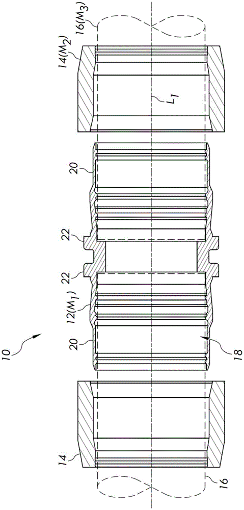
转到图1至图3,图示出了可以连接到两个或更多个流体元件的示例接头10。出于本公开内容的目的,“流体元件”是指管道、管、接头或被配置为传送、递送和/或接收流体的任何其他元件。此外,“接头”是指可以连接到两个或更多个流体元件以将两个或更多个流体元件流体地耦接在一起的任何元件。Turning to FIGS. 1-3 , an example joint 10 that may be connected to two or more fluid elements is illustrated. For purposes of this disclosure, "fluid element" refers to a conduit, tube, fitting, or any other element configured to communicate, deliver, and/or receive fluid. Furthermore, "joint" refers to any element that can be connected to two or more fluidic elements to fluidly couple the two or more fluidic elements together.
图1至图3示出了接头10的沿平行于纵向轴线L1并且含有纵向轴线L1的平面截取的横截面图。如在图1至图3中所布置的接头10的部件大体上关于纵向轴线L1对称,使得该接头10的部件以对称的方式完全地围绕纵向轴线L1延伸。图1示出了大体上沿纵向轴线L1对准的接头10的部件。同时,图2和图3分别示出了处于预安装配置和处于安装配置的接头10的一个侧部(即,如在图1中所见的右侧部)。应当理解,接头10的相反侧部(即,如在图1中所见的左侧部)可以包括沿纵向轴线L1镜像的类似的或相同的配置。1 to 3 show cross -sectional views of the joint 10 taken along a plane parallel to and containing the longitudinal axis L 1 . The components of the joint 10 as arranged in FIGS. 1 to 3 are generally symmetrical about the longitudinal axis L 1 such that the components of the joint 10 extend completely around the longitudinal axis L 1 in a symmetrical manner. Figure 1 shows the components of the joint 10 generally aligned along the longitudinal axis L1 . Meanwhile, FIGS. 2 and 3 show one side (ie, the right side as seen in FIG. 1 ) of the joint 10 in a pre-installed configuration and in an installed configuration, respectively. It should be appreciated that the opposite side of joint 10 (ie, the left side as seen in FIG. 1 ) may comprise a similar or identical configuration mirrored along longitudinal axis L 1 .
在本示例中的接头10包含耦接主体12和两个驱动环14(有时称为“旋锻环”),该驱动环14可以在耦接主体12上滑动以将一对管道主体16接合到接头10,如下面进一步讨论的。本申请可适用于的管道16可以是薄壁管道或厚壁管道,诸如尺寸范围从1/4”NPS到4”NPS,或者甚至高达6”NPS或更大值的那些管道。此外,每个管道16的外径(Do)除以壁厚(t)的比率(Do/t)可以在约1至约100之间、约2至约70之间、约3至约40之间、或者约4.5到约30之间。然而,其他管道尺寸也可以适用于示例接头10。此外,接头10可以类似地连接到诸如法兰、三通和其他接头的其他类型的流体元件。The
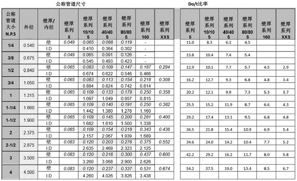
表1——管道或管的直径与壁厚的比率计算(Do/t)Table 1 - Calculation of ratio of pipe or tube diameter to wall thickness (Do/t)
如在图2和图3中示出的,耦接主体12限定孔18,该孔18延伸穿过耦接主体12,用于在该孔18中在每个端部处接收管道16。因此,接头10用于以密封的、不泄漏的方式流体地耦接两个管道16。耦接主体12关于孔18的中心轴线X1对称地延伸,并且包含套筒部分20、凸缘部分22和密封部分24。此外,密封部分24包含用于连接到管道16的外部的至少一个密封部,并且在所图示的实施例中包含主密封部30、内侧密封部32和外侧密封部34,其中,每个密封部30、32、34包括从套筒部分20径向地向内延伸的一个或多个齿38。可以预见的是,密封部分24可以包含其他数量和/或布置的密封部。驱动环14类似地是中心开口的主体,该驱动环14限定延伸穿过驱动环14的孔46,用于在该孔46中接收耦接主体12。此外,驱动环14关于孔46的中心轴线X2对称地延伸。As shown in FIGS. 2 and 3 , the
耦接主体12和驱动环14可以首先组装成在图2中所示出的预安装配置。具体地,驱动环14可以被布置在耦接主体12的端部上方,使得耦接主体12和驱动环14的中心轴线X1、X2与纵向轴线L1共线,并且耦接主体12被布置在驱动环14的孔46内。在该配置中,驱动环14的斜升区段54将与耦接主体12的台阶区段56毗邻,但相对于该台阶区段56稍有间隔。通过过盈配合,驱动环14可以在预安装配置中保持在耦接主体12上并运送给客户,这有利于终端用户的易用性和易安装性。The
为了将接头10安装到管道16上,管道16可以位于耦接主体12的孔18内,而接头10处于接头10的预安装配置(图2)。驱动环14然后可以沿纵向轴线L1朝向耦接主体12的凸缘部分22轴向地受力,直到接头10呈现接头10的安装配置(图3)。驱动环14和耦接主体12具有预定的过盈比率,使得驱动环14向安装配置的轴向移动引起耦接主体12、驱动环14和管道16变形,由此产生这些元件的机械的连接,其中在管道16和耦接主体12之间存在金属对金属不泄漏密封。To install the fitting 10 to the
更具体地,随着驱动环14沿纵向轴线L1朝向凸缘部分22轴向地受力,驱动环14向耦接主体12施加压缩力,该压缩力引起主体12的径向变形,从而迫使该主体12的密封部30、32、34的齿38咬合到管道16中。耦接主体12依次地首先弹性地(即,非永久性地)压缩管道16,然后塑性地(即,永久性地)压缩管道16。该压缩是足够强的以使管道16在密封接合区下方塑性地屈服,从而在管道16和耦接主体12之间形成360°周向的、永久的、金属对金属密封。在主体12和管道16的径向压缩的同时,驱动环14径向地向外膨胀。驱动环14的这种径向膨胀是弹性的,并且导致驱动环14的直径的小幅增加。More specifically, as
当密封部的齿38完全地被迫变形成接触管道16时(例如,当管道16的与密封部30、32、34紧靠相对的外表面58没有进一步的径向移动时,作为通过驱动环14的特定区段被迫向内的结果),认为密封部的设置完成。或者,一个或多个密封部的完全设置可以定义为当驱动环14已经迫使密封部的齿38最远地进入到管道16中时、或者随着驱动环14移动经过密封部,当驱动环14的致动锥度逐渐变平至直径恒定的圆柱形区段时。随着密封部30、32、34继续咬合到表面58中,管道16通常变得应变超过管道16的弹性极限,并且管道16开始塑性地变形或者径向地向内移动,从而导致永久变形。密封部30、32、34的齿38咬合到管道16的外表面58中并且使该外表面58变形,并且密封部30、32、34的齿38本身可能会有些变形。这用于填充在管道16的外侧发现的任何粗糙的或不规则的表面缺陷。When the
一旦安装,驱动环14将邻接或接合凸缘部分22(尽管在其他示例中,驱动环14可以与凸缘部分22间隔开)。此外,由于驱动环14在安装期间弹性地变形,使得该驱动环14径向地向外膨胀,驱动环14将施加持续的弹性力压紧耦接主体12和管道16,在安装后,在接头10的使用寿命期间保持该持续的弹性力,由此防止管道16和耦接主体12之间的金属对金属密封的释放。Once installed, the
如上所讨论的,所图示的实施例的耦接主体12的密封部分24包含主密封部30、内侧密封部32和外侧密封部34,其中,每个密封部30、32、34包括一个或多个齿38,该齿38从套管部分20径向地向内延伸,并且在接头10的安装期间咬合到管道16中。在一些实施例中,密封部30、32、34优选地分布在孔18的轴向长度上,该轴向长度是在管道16的外径的约60%到约75%之间。当密封部30、32、34被分布在该范围内时,可以消散由来自极端热暴露的应力施加在接头10上的负载,并且可以减少在材料疲劳开始处的焦点应力集中。As discussed above, the
应当理解,在不脱离本公开内容的范围的情况下,可以对接头10的耦接主体12和驱动环14进行各种修改。例如,耦接主体12可以是凸缘主体,如下面进一步讨论的。此外,耦接主体12可以是具有两个以上腿部的T形主体或Y形主体,并且接头10可以包含多个驱动环14,每个驱动环14可以被迫使在不同的腿部上以将流体接头10连接到流体元件。作为另一示例,耦接主体12可以被配置为仅接收一个流体元件,并且接头10可以仅包含单个驱动环14以将耦接主体12机械地附接至流体元件。It should be understood that various modifications may be made to the
广义上讲,耦接主体12和驱动环14可以是限定穿过主体的孔的任何主体,使得耦接主体12可以接收流体元件并且驱动环14可以被迫使在耦接主体12上以压缩耦接主体12并将耦接主体12机械地附接到流体元件。例如,在共同拥有的美国专利号10,663,093、8,870,237、7,575,257、6,692,040、6,131,964、5,709,418、5,305,510和5,110,163中描述了具有耦接主体和驱动环的各种示例接头,这些美国专利均通过全文引用明确地并入本文中。Broadly speaking,
上面已使用术语“轴向的”、“径向的”及其变体来描述耦接主体12、驱动环14和管道16的各种特征。应当理解,除非另外明确地指出,否则上面(以及下面)使用的那些术语是相对于所描述的元件的中心轴线而言。即,除非另外明确地指出,否则当描述耦接主体12的特征时,术语“轴向的”、“径向的”及其变体是相对于耦接主体的中心轴线X1而言,当描述驱动环14的特征时,术语“轴向的”、“径向的”及其变体是相对于驱动环的中心轴线X2而言,并且当描述管道16的特征时,术语“轴向的”、“径向的”及其变体是相对于管道的中心轴线而言。此外,应当理解,在耦接主体12、驱动环14和管道16的中心轴线彼此共线并且为共同轴线的配置中(参见例如图1至图3),当描述耦接主体12、驱动环14和管道16的特征时,术语“轴向的”“径向的”及其变体将类似地相对于耦接主体12、驱动环14和管道16的共同轴线和所有中心轴线而言。The terms “axial,” “radial,” and variations thereof have been used above to describe various features of the
本发明人已经发现,上面描述的接头10及接头10与管道16的机械的附接使得能够使用用于接头10和/或管道16的通常不适合或妨碍管道和接头之间的焊接连接的材料。The inventors have found that the above-described
例如,本实施例中的耦接主体12、驱动环14和管道16是单体式主体,意味着耦接主体12、驱动环14和管道16的每一个都是单个的材料主体。特别地,耦接主体12、驱动环14和管道16分别包括第一材料M1、第二材料M2和第三材料M3。这些材料M1、M2、M3中的任何材料或所有材料可以包括双相不锈钢DSS,该双相不锈钢DSS具有包括奥氏体和铁素体二者的双相微观结构。与标准奥氏体不锈钢相比,铁素体相赋予双相不锈钢DSS更高的强度,并且铁素体相提供对氯化物应力腐蚀开裂的显着的抵抗(氯化物是在这些接头的工业油气装置中常见的腐蚀性化学品)。此外,奥氏体相为双相不锈钢DSS提供足够的延展性。延展性可以减少在接头10中和/或在管道16中的微裂纹的出现,该微裂纹的出现可能在安装期间发生并且允许腐蚀性化学品进入并最终损害接头10的强度。For example, the
通过改变奥氏体和铁素体之间的微观结构比例,可以修改双相不锈钢DSS的强度、防腐性和延展性,以实现预期的目的。在一个或多个实施例中,双相不锈钢DSS的奥氏体与铁素体的比率(即,奥氏体质量除以铁素体质量的比率)可以为约35%至约65%、约40%至约60%或约45%至约55%。在优选的实施例中,双相不锈钢的奥氏体与铁素体的比率可以为约50%。By changing the microstructural ratio between austenite and ferrite, the strength, corrosion resistance and ductility of duplex stainless steel DSS can be modified to achieve the intended purpose. In one or more embodiments, the ratio of austenite to ferrite (i.e., the ratio of the mass of austenite divided by the mass of ferrite) of the duplex stainless steel DSS may be from about 35% to about 65%, about 40% to about 60% or about 45% to about 55%. In a preferred embodiment, the duplex stainless steel may have a ratio of austenite to ferrite of about 50%.
双相不锈钢DSS的化学成分可以包括(按质量%计):最少约25%质量的铬、最少约2%质量的钼和最少约6.5%质量的镍。此外,在本申请中使用的双相不锈钢DSS是超级双相钢或者超双相钢,该超级双相钢具有约40或更大的PREN(即,耐点蚀当量),超双相钢具有约45或更大的PREN。优选地,双相不锈钢DSS是超级双相钢/超双相钢,该超级双相钢/超双相钢的奥氏体和铁素体的比例在约35%至约65%之间,超级双相钢/超双相钢具有最小约40的PREN和最少约25%质量的化学成分的铬、最少约2%质量的钼和最少约6.5%质量的镍。但是,双相不锈钢DSS的成分可以根据实施方式而变化,并且双相不锈钢DSS中每种金属的相对含量可以基于使用环境、制造商的建议、经验等。The chemical composition of the duplex stainless steel DSS may include (in mass %): a minimum of about 25% by mass of chromium, a minimum of about 2% by mass of molybdenum, and a minimum of about 6.5% by mass of nickel. In addition, the duplex stainless steel DSS used in this application is a super duplex steel or super duplex steel, the super duplex steel has a PREN (ie, pitting resistance equivalent) of about 40 or greater, and the super duplex steel has PREN of about 45 or greater. Preferably, the duplex stainless steel DSS is a super duplex steel/super duplex steel, the ratio of austenite and ferrite of the super duplex steel/super duplex steel is between about 35% and about 65%, super duplex steel/super duplex steel The dual phase/super duplex steel has a PREN of about 40 minimum and a chemical composition of about 25% by mass minimum of chromium, a minimum of about 2% by mass of molybdenum, and a minimum of about 6.5% by mass of nickel. However, the composition of the duplex stainless steel DSS may vary according to embodiments, and the relative content of each metal in the duplex stainless steel DSS may be based on the use environment, manufacturer's suggestion, experience, and the like.
包括双相不锈钢DSS的一个或多个元件(例如,耦接主体12、驱动环14和/或管道16)可以使用冷加工工艺或冷成型工艺形成,这些工艺可以借助于应变硬化技术机械地增强双相不锈钢DSS。在一些实施例中,双相不锈钢DDS可以应变硬化至约洛氏C级32的硬度水平。One or more elements comprising duplex stainless steel DSS (e.g., coupling
例如,每个元件可以通过冷皮尔格工艺形成,在该冷皮尔格工艺中,渐缩的芯轴被插入到包括双相不锈钢DSS的工件(例如管道或管)的孔中,并且一对顶部模具和底部模具被迫使在工件的外径的上并且围绕工件的外径。芯轴保持工件的内径,而模具减小外径,由此在单个步骤中减小工件的外径和厚度。For example, each element may be formed by a cold pilger process in which a tapered mandrel is inserted into a bore in a workpiece (such as a pipe or tube) comprising duplex stainless steel DSS, and a pair of top The die and bottom die are forced onto and around the outer diameter of the workpiece. The mandrel maintains the inner diameter of the workpiece, while the die reduces the outer diameter, thereby reducing the outer diameter and thickness of the workpiece in a single step.
作为另一示例,每个元件可以通过冷拔工艺形成,在该冷拔工艺中,包括双相不锈钢DSS的工件被迫使通过单个模具或一系列模具,由此减小工件的横截面大小。冷拔可以实现横截面减少约15%至约30%之间。As another example, each element may be formed by a cold drawing process in which a workpiece comprising duplex stainless steel DSS is forced through a single die or series of dies, thereby reducing the cross-sectional size of the workpiece. Cold drawing can achieve a cross-sectional reduction of between about 15% and about 30%.
图4A示出了管道16的光学显微图像,该管道16包括具有优选的微观结构比例的双相不锈钢材料,用于与接头10一起使用。较亮的区域代表奥氏体物质,而较暗的区域代表铁素体物质。图4B示出了管道16在被耦接到接头10之后的光学显微图像。正如在图4B中明显的,管道16具有足够的延展性以与接头10(以黑色显示)耦接,而不会显着地改变管道16的微观结构。这些图表明,与通过焊接附接的常规接头不同,本接头10能够使管道16和接头10机械地耦接,而不会对双相不锈钢材料的微观结构比例产生任何显着的改变。因此,与焊接工艺不同,双相不锈钢能够更容易地保持双相不锈钢的强度、延展性和抗腐蚀性能。FIG. 4A shows an optical microscopic image of
在本实施例中的耦接主体12、驱动环14和管道16各自均包括相同的双相不锈钢材料。然而,应当理解,耦接主体12、驱动环14和管道16可以包括彼此类似或基本上不同的双相不锈钢材料。例如,耦接主体12和驱动环14可以包括与管道16的双相不锈钢材料相比,在成分、PREN和/或奥氏体和铁素体的比例方面不同的双相不锈钢材料。优选地,用于耦接主体12、驱动环14和管道16的双相不锈钢材料M1、M2、M3将是在ASME编号ASME B31.3-2016中列出的等级(例如,用于在关键工艺和电力管道中可接受的用途)。The
上面描述的接头10的另一优点是接头10的机械的附接使得接头10和管道16能够包括彼此基本上不同的材料,而用于连接接头和管道的常规焊接工艺要求被焊接在一起的部件具有基本上类似的成分。因此,在一些实施例中,接头10和管道16的一个或多个元件(例如,耦接主体12和驱动环14)可以包括双相不锈钢材料,而一个或多个其他元件(例如,管道16)可以包括非双相不锈钢材料,该非双相不锈钢材料包括但不限于碳钢、中合金钢和低合金钢、以及不锈钢。在接头10包括应变硬化双相不锈钢并且耦接到包括非双相不锈钢的管道16的情况下,非双相不锈钢管道16可以具有80ksi或更低的屈服强度。此外,由于双相不锈钢比诸如碳钢的其他合金钢更贵重,并且因此更耐腐蚀,接头10可以更耐双金属腐蚀的影响。Another advantage of the joint 10 described above is that the mechanical attachment of the joint 10 enables the joint 10 and the
再进一步地,通过用双相不锈钢形成耦接主体12,与由延展性较差的材料制成的耦接主体相比,可以形成独特的密封几何形状。更具体地,用其他金属合金制成的耦接主体通常需要尖锐的齿来与流体元件形成充分的密封。然而,双相不锈钢的使用可以使耦接主体12的齿38具有更平的或更圆的轮廓,而不会牺牲密封的强度或结构完整性。Still further, by forming the
例如,图5和图6示出了用于耦接主体12的每个齿38的不同示例配置,两张图都是沿平行于中心轴线X1并且含有中心轴线X1的平面截取的横截面图。如在图5中所示出的,耦接主体的密封部分24的每个齿38均可以从套筒部分20在根部64处开始向齿38的远端部66径向地向内延伸。每个齿38可以具有内侧齿面68、外侧齿面70和远端面74,该远端面74在内侧齿面68和外侧齿面70之间延伸并且与内侧齿面68和外侧齿面70在相应的边缘78处相交。齿面68、70可以成角度,使得齿面68、70倾斜于耦接主体12的中心轴线X1延伸。特别地,每个齿面68、70与径向方向之间的角度α可以是约30度至约40度。此外,远端面74可以具有基本上平的且基本上平行于中心轴线X1延伸的横截面轮廓。For example, FIGS. 5 and 6 show different example configurations for each
在其他示例中(参见例如图6),齿面68、70可以成角度,使得每个齿面68、70与径向方向之间的角度α为约40度至约50度。此外,远端面74的横截面轮廓可以是圆拱形的,具有约0.010”至约0.050”的曲率半径。无论是平的还是圆拱形的,横截面轮廓将优选地具有约0.005”至约0.040”的长度(对于圆拱形轮廓,应当理解,圆拱形轮廓的“长度”是指圆拱形轮廓的弧长)。In other examples (see, eg, FIG. 6 ), the tooth flanks 68 , 70 may be angled such that the angle α between each
每个边缘78可以是具有相对大的曲率半径的倒圆边缘,使得齿38的相应的齿面68、70和远端面74之间的界面是平滑的且连续的,没有任何尖锐的或不连续的过渡。在其他实施例中,每个边缘78可以具有相对较小的曲率半径,该曲率半径小到足以在齿38的相应的齿面68、70和远端面74之间产生可辨别的、不连续的界面。当从一距离观察时,这种不连续的界面可以近似于齿38的相关的齿面68、70和远端面74之间的尖锐边缘。优选地,每个边缘78将具有约0.003”至约0.005”的曲率半径。还应当理解,在一些实施例中,齿面68、70可以与远端面74形成波状的表面,使得齿面68、70与远端面74之间不存在明确限定的边缘。Each
因此,与包括非双相不锈钢的常规耦接主体的更尖锐的齿相比,每个齿38可以具有基本上梯形的横截面轮廓,该基本上梯形的横截面轮廓更加坚固并且提供更大的质量来向下压靠管道16。与常规齿相比,每个齿38的质量也可以更大,这可以使得耦接主体12能够接合质量较差的管道表面。Thus, each
上面描述的接头10的另一优点是减少易燃液体或气体的泄漏的能力,特别是当接头10被暴露于火灾和/或高频率振动时。这可以通过适当比率的材料演变来实现,该材料演变通过在耦接主体12、驱动环14和管道16之间沿着它们的接触区域的轴向长度的应变硬化和干涉来实现。此外,接头10消除了对焊接的连接部进行热处理的需要,而对焊接的连接部进行热处理对于在腐蚀性环境中的焊接是通常需要的。Another advantage of the fitting 10 described above is the ability to reduce the leakage of flammable liquids or gases, especially when the fitting 10 is exposed to fire and/or high frequency vibrations. This can be achieved by an appropriate rate of material evolution through strain hardening and interference between the
转向图7A和图7B,现在将描述形成用于接头10的示例耦接主体12'的工艺。如在图7A中所示出的,提供了初始工件100,该工件100包括根据上面描述的单个的、单体式的双相不锈钢主体。工件100包含凸缘部分102和从凸缘部分102延伸的圆柱形部分104。圆柱形部分104可以进行冷加工以获得所期望的材料机械强度和材料微观结构水平,并且然后在高公差下进行机加工以形成最终的耦接主体12',如在图7B中所示出的。Turning to FIGS. 7A and 7B , the process of forming the
因此,最终的耦接主体12'将是单个的、单体式的双相不锈钢主体。然而,取决于材料的化学性质,耦接主体12'的由工件100的圆柱形部分104形成的特定部分(例如,耦接主体12'的套筒部分20、凸缘部分22和密封部分24)将通过材料的冷加工减少约20%或更少的过程而被应变硬化。同时,耦接主体12'的其他部分(例如,凸缘部分102)将不会被应变硬化。然而,耦接主体12'的已机械地增强的部分和未机械地增强的部分之间的过渡区域将通过在工件的基材中的奥氏体和铁素体的比例来保持相对均匀的耐腐蚀性。Thus, the final coupling body 12' will be a single, monolithic duplex stainless steel body. However, depending on the chemistry of the material, certain portions of the coupling body 12' formed by the
应当理解,上面描述的用于形成耦接主体12'的工艺可以类似地应用以形成其他耦接主体,诸如在图1至图3中所图示的耦接主体12。即,可以对初始工件进行冷加工,并且然后进行机加工以形成在图1至图3中的耦接主体12或者形成用于流体接头的其他类型的耦接主体。类似地,使用在本文中讨论的方法和材料可以制造各种其他类型或配置的耦接主体,该耦接主体包括但不限于90度弯头、T形件、适配器、帽、各种角度的弯头、异径管、三通、连接器等。It should be understood that the processes described above for forming coupling body 12' may be similarly applied to form other coupling bodies, such as
已经参考上面描述的示例实施例描述了本发明。其他人在阅读和理解本说明书后将会做出修改和更改。结合本发明的一个或多个方面的示例实施例旨在包含所有这些修改和更改,只要它们落入所附的权利要求的范围内。The invention has been described with reference to the example embodiments described above. Modifications and alterations will occur to others upon reading and understanding this specification. Example embodiments incorporating one or more aspects of the invention are intended to embrace all such modifications and alterations insofar as they come within the scope of the appended claims.
Claims (20)
Applications Claiming Priority (3)
| Application Number | Priority Date | Filing Date | Title |
|---|---|---|---|
| US202063014392P | 2020-04-23 | 2020-04-23 | |
| US63/014,392 | 2020-04-23 | ||
| PCT/US2021/028851 WO2021217008A1 (en) | 2020-04-23 | 2021-04-23 | Fluid system comprising duplex stainless steel |
Publications (1)
| Publication Number | Publication Date |
|---|---|
| CN115715355A true CN115715355A (en) | 2023-02-24 |
Family
ID=78221970
Family Applications (1)
| Application Number | Title | Priority Date | Filing Date |
|---|---|---|---|
| CN202180029919.1A Pending CN115715355A (en) | 2020-04-23 | 2021-04-23 | Fluid system comprising duplex stainless steel |
Country Status (9)
| Country | Link |
|---|---|
| US (1) | US20210332918A1 (en) |
| EP (1) | EP4139597A4 (en) |
| JP (1) | JP7546692B2 (en) |
| KR (1) | KR102800540B1 (en) |
| CN (1) | CN115715355A (en) |
| AU (1) | AU2021261014B2 (en) |
| CA (1) | CA3172991A1 (en) |
| MX (1) | MX2022013139A (en) |
| WO (1) | WO2021217008A1 (en) |
Cited By (1)
| Publication number | Priority date | Publication date | Assignee | Title |
|---|---|---|---|---|
| CN117189964A (en) * | 2023-09-26 | 2023-12-08 | 珠海格力电器股份有限公司 | Heat pump equipment and pipeline connection sealing components |
Citations (7)
| Publication number | Priority date | Publication date | Assignee | Title |
|---|---|---|---|---|
| US5114191A (en) * | 1990-03-22 | 1992-05-19 | Lokring Corporation | Pipe fitting with coupling body and improved isolation tooth arrangement |
| EP2020553A2 (en) * | 2007-07-30 | 2009-02-04 | Cold Work Technology Limited | Axial swage connectors |
| CN101694255A (en) * | 2004-04-22 | 2010-04-14 | 斯瓦戈洛克公司 | Fitting for taper screw cap |
| US20140291981A1 (en) * | 2011-08-03 | 2014-10-02 | Gardner T. Baldwin | End connector for high pressure high temperature reinforced rubber hose |
| CN107002921A (en) * | 2014-12-09 | 2017-08-01 | 通用电气石油和天然气英国有限公司 | End connector and manufacture method |
| KR101883492B1 (en) * | 2018-01-22 | 2018-08-27 | 주식회사 디오하베스트 | The pipe connection device without welding connection method |
| CN108480970A (en) * | 2017-07-24 | 2018-09-04 | 西北工业大学 | A kind of Aluminum Alloy Tube plastic joining method based on spinning |
Family Cites Families (15)
| Publication number | Priority date | Publication date | Assignee | Title |
|---|---|---|---|---|
| US3477750A (en) * | 1967-10-30 | 1969-11-11 | Jonathan S Powell | Pipe coupling and means and method of assembly |
| US5110163A (en) | 1990-03-22 | 1992-05-05 | Lokring Corporation | Pipe fitting with improved coupling body |
| AU7586791A (en) | 1990-04-06 | 1991-10-30 | Lokring Corporation | Hydraulic assembly tool with improved load bearing arrangement for tube fittings |
| US5181752A (en) * | 1990-06-26 | 1993-01-26 | Lokring Corporation | Pipe fitting with swage ring locking mechanism |
| US5709418A (en) | 1995-03-20 | 1998-01-20 | Lokring Corporation | Pipe fitting with coupling body and swage ring with kickdown device to prevent reduction in sealing tooth contact force |
| US6131964A (en) * | 1998-12-15 | 2000-10-17 | Westinghouse Air Brake Company | SAS fitting for tube and pipe connections |
| US6692040B1 (en) | 2000-10-03 | 2004-02-17 | Lokring Technology Corporation | Lokring fitting having improved anti-torsion capability |
| US7575257B2 (en) * | 2005-02-24 | 2009-08-18 | Lokring Technology Corporation | Fitting with sequential sealing action |
| GB0503954D0 (en) * | 2005-02-25 | 2005-04-06 | Parker Hannifin Ipde | Connector and method of connecting tubes, pipes and round sections |
| KR101365539B1 (en) * | 2005-10-11 | 2014-02-20 | 록링 테크놀로지 엘엘씨 | Improved fitting with complementary fitting materials |
| WO2011082417A2 (en) | 2010-01-04 | 2011-07-07 | Lokring Technology, Llc | Mechanically attached fitting for use in a sour environment |
| CA2864762C (en) * | 2012-02-17 | 2019-06-04 | 8193053 Canada Ltd. | Pipe, pipe connection and pipeline system |
| US20130270821A1 (en) * | 2012-04-12 | 2013-10-17 | Gottfried Haener | Coupling assembly that establishes a pipe connection through pressure clamping |
| JP6968073B2 (en) * | 2015-09-24 | 2021-11-17 | レンロック ホールディングズ エルエルシーLenlok Holdings, LLC | Pipe fitting with sensor |
| KR101967642B1 (en) * | 2017-08-23 | 2019-04-10 | 주식회사 메가조인트 | Pipe connection apparatus |
-
2021
- 2021-04-23 CN CN202180029919.1A patent/CN115715355A/en active Pending
- 2021-04-23 US US17/238,803 patent/US20210332918A1/en not_active Abandoned
- 2021-04-23 JP JP2022564419A patent/JP7546692B2/en active Active
- 2021-04-23 AU AU2021261014A patent/AU2021261014B2/en active Active
- 2021-04-23 WO PCT/US2021/028851 patent/WO2021217008A1/en not_active Ceased
- 2021-04-23 EP EP21792219.4A patent/EP4139597A4/en active Pending
- 2021-04-23 CA CA3172991A patent/CA3172991A1/en active Pending
- 2021-04-23 KR KR1020227036299A patent/KR102800540B1/en active Active
- 2021-04-23 MX MX2022013139A patent/MX2022013139A/en unknown
Patent Citations (7)
| Publication number | Priority date | Publication date | Assignee | Title |
|---|---|---|---|---|
| US5114191A (en) * | 1990-03-22 | 1992-05-19 | Lokring Corporation | Pipe fitting with coupling body and improved isolation tooth arrangement |
| CN101694255A (en) * | 2004-04-22 | 2010-04-14 | 斯瓦戈洛克公司 | Fitting for taper screw cap |
| EP2020553A2 (en) * | 2007-07-30 | 2009-02-04 | Cold Work Technology Limited | Axial swage connectors |
| US20140291981A1 (en) * | 2011-08-03 | 2014-10-02 | Gardner T. Baldwin | End connector for high pressure high temperature reinforced rubber hose |
| CN107002921A (en) * | 2014-12-09 | 2017-08-01 | 通用电气石油和天然气英国有限公司 | End connector and manufacture method |
| CN108480970A (en) * | 2017-07-24 | 2018-09-04 | 西北工业大学 | A kind of Aluminum Alloy Tube plastic joining method based on spinning |
| KR101883492B1 (en) * | 2018-01-22 | 2018-08-27 | 주식회사 디오하베스트 | The pipe connection device without welding connection method |
Cited By (1)
| Publication number | Priority date | Publication date | Assignee | Title |
|---|---|---|---|---|
| CN117189964A (en) * | 2023-09-26 | 2023-12-08 | 珠海格力电器股份有限公司 | Heat pump equipment and pipeline connection sealing components |
Also Published As
| Publication number | Publication date |
|---|---|
| KR20220151212A (en) | 2022-11-14 |
| JP7546692B2 (en) | 2024-09-06 |
| EP4139597A1 (en) | 2023-03-01 |
| US20210332918A1 (en) | 2021-10-28 |
| MX2022013139A (en) | 2022-11-16 |
| CA3172991A1 (en) | 2021-10-28 |
| AU2021261014B2 (en) | 2024-09-12 |
| WO2021217008A1 (en) | 2021-10-28 |
| KR102800540B1 (en) | 2025-04-24 |
| EP4139597A4 (en) | 2024-08-14 |
| JP2023523735A (en) | 2023-06-07 |
| AU2021261014A1 (en) | 2022-10-13 |
Similar Documents
| Publication | Publication Date | Title |
|---|---|---|
| EP2521874B1 (en) | Mechanically attached fitting for use in a sour environment | |
| US4556240A (en) | Corrosion-resistant, double-wall pipe structures | |
| EP1967690B1 (en) | High-strength sealed connection for expandable tubulars | |
| US8308201B2 (en) | Crimp fitting for corrugated stainless steel tubing | |
| US6450553B1 (en) | Axial swage fitting for large bore pipes and tubes | |
| EP1948985B1 (en) | Improved fitting with complementary fitting materials | |
| CN107002914B (en) | Fluid conduit element and method for forming a fluid conduit element | |
| EP3389919B1 (en) | Method for connection and tubular connection assembly for improved fatigue performance of metallic risers | |
| JP7546692B2 (en) | Fluid Systems Containing Duplex Stainless Steels | |
| CN112262278B (en) | Kit for connection to at least one tube | |
| HK40085845A (en) | Fluid system comprising duplex stainless steel | |
| EP4279788B1 (en) | Push-fitting | |
| JP7292314B2 (en) | Tubular elements and tubular assemblies | |
| JPS58122198A (en) | Construction of welded joint of corrosion resistant pipe | |
| CN114945730A (en) | Threaded joint with sealed bearing by additive manufacturing | |
| JPS6152351B2 (en) |
Legal Events
| Date | Code | Title | Description |
|---|---|---|---|
| PB01 | Publication | ||
| PB01 | Publication | ||
| SE01 | Entry into force of request for substantive examination | ||
| SE01 | Entry into force of request for substantive examination | ||
| REG | Reference to a national code |
Ref country code: HK Ref legal event code: DE Ref document number: 40085845 Country of ref document: HK |