CN115705655A - System and method for intraoperative determination of image alignment - Google Patents
System and method for intraoperative determination of image alignment Download PDFInfo
- Publication number
- CN115705655A CN115705655A CN202210960356.4A CN202210960356A CN115705655A CN 115705655 A CN115705655 A CN 115705655A CN 202210960356 A CN202210960356 A CN 202210960356A CN 115705655 A CN115705655 A CN 115705655A
- Authority
- CN
- China
- Prior art keywords
- image
- angle
- intra
- operative
- intraoperative
- Prior art date
- Legal status (The legal status is an assumption and is not a legal conclusion. Google has not performed a legal analysis and makes no representation as to the accuracy of the status listed.)
- Pending
Links
Images


Classifications
-
- A—HUMAN NECESSITIES
- A61—MEDICAL OR VETERINARY SCIENCE; HYGIENE
- A61B—DIAGNOSIS; SURGERY; IDENTIFICATION
- A61B90/00—Instruments, implements or accessories specially adapted for surgery or diagnosis and not covered by any of the groups A61B1/00 - A61B50/00, e.g. for luxation treatment or for protecting wound edges
- A61B90/36—Image-producing devices or illumination devices not otherwise provided for
- A61B90/37—Surgical systems with images on a monitor during operation
-
- G—PHYSICS
- G06—COMPUTING OR CALCULATING; COUNTING
- G06T—IMAGE DATA PROCESSING OR GENERATION, IN GENERAL
- G06T7/00—Image analysis
- G06T7/0002—Inspection of images, e.g. flaw detection
- G06T7/0012—Biomedical image inspection
- G06T7/0014—Biomedical image inspection using an image reference approach
-
- A—HUMAN NECESSITIES
- A61—MEDICAL OR VETERINARY SCIENCE; HYGIENE
- A61B—DIAGNOSIS; SURGERY; IDENTIFICATION
- A61B34/00—Computer-aided surgery; Manipulators or robots specially adapted for use in surgery
- A61B34/10—Computer-aided planning, simulation or modelling of surgical operations
-
- A—HUMAN NECESSITIES
- A61—MEDICAL OR VETERINARY SCIENCE; HYGIENE
- A61B—DIAGNOSIS; SURGERY; IDENTIFICATION
- A61B34/00—Computer-aided surgery; Manipulators or robots specially adapted for use in surgery
- A61B34/25—User interfaces for surgical systems
-
- G—PHYSICS
- G06—COMPUTING OR CALCULATING; COUNTING
- G06T—IMAGE DATA PROCESSING OR GENERATION, IN GENERAL
- G06T7/00—Image analysis
- G06T7/30—Determination of transform parameters for the alignment of images, i.e. image registration
- G06T7/33—Determination of transform parameters for the alignment of images, i.e. image registration using feature-based methods
-
- A—HUMAN NECESSITIES
- A61—MEDICAL OR VETERINARY SCIENCE; HYGIENE
- A61B—DIAGNOSIS; SURGERY; IDENTIFICATION
- A61B34/00—Computer-aided surgery; Manipulators or robots specially adapted for use in surgery
- A61B34/10—Computer-aided planning, simulation or modelling of surgical operations
- A61B2034/101—Computer-aided simulation of surgical operations
- A61B2034/102—Modelling of surgical devices, implants or prosthesis
-
- A—HUMAN NECESSITIES
- A61—MEDICAL OR VETERINARY SCIENCE; HYGIENE
- A61B—DIAGNOSIS; SURGERY; IDENTIFICATION
- A61B34/00—Computer-aided surgery; Manipulators or robots specially adapted for use in surgery
- A61B34/10—Computer-aided planning, simulation or modelling of surgical operations
- A61B2034/108—Computer aided selection or customisation of medical implants or cutting guides
-
- A—HUMAN NECESSITIES
- A61—MEDICAL OR VETERINARY SCIENCE; HYGIENE
- A61B—DIAGNOSIS; SURGERY; IDENTIFICATION
- A61B34/00—Computer-aided surgery; Manipulators or robots specially adapted for use in surgery
- A61B34/25—User interfaces for surgical systems
- A61B2034/252—User interfaces for surgical systems indicating steps of a surgical procedure
-
- A—HUMAN NECESSITIES
- A61—MEDICAL OR VETERINARY SCIENCE; HYGIENE
- A61B—DIAGNOSIS; SURGERY; IDENTIFICATION
- A61B34/00—Computer-aided surgery; Manipulators or robots specially adapted for use in surgery
- A61B34/25—User interfaces for surgical systems
- A61B2034/254—User interfaces for surgical systems being adapted depending on the stage of the surgical procedure
-
- A—HUMAN NECESSITIES
- A61—MEDICAL OR VETERINARY SCIENCE; HYGIENE
- A61B—DIAGNOSIS; SURGERY; IDENTIFICATION
- A61B90/00—Instruments, implements or accessories specially adapted for surgery or diagnosis and not covered by any of the groups A61B1/00 - A61B50/00, e.g. for luxation treatment or for protecting wound edges
- A61B90/36—Image-producing devices or illumination devices not otherwise provided for
- A61B90/37—Surgical systems with images on a monitor during operation
- A61B2090/376—Surgical systems with images on a monitor during operation using X-rays, e.g. fluoroscopy
-
- G—PHYSICS
- G06—COMPUTING OR CALCULATING; COUNTING
- G06T—IMAGE DATA PROCESSING OR GENERATION, IN GENERAL
- G06T2207/00—Indexing scheme for image analysis or image enhancement
- G06T2207/10—Image acquisition modality
- G06T2207/10116—X-ray image
- G06T2207/10121—Fluoroscopy
-
- G—PHYSICS
- G06—COMPUTING OR CALCULATING; COUNTING
- G06T—IMAGE DATA PROCESSING OR GENERATION, IN GENERAL
- G06T2207/00—Indexing scheme for image analysis or image enhancement
- G06T2207/30—Subject of image; Context of image processing
- G06T2207/30004—Biomedical image processing
- G06T2207/30008—Bone
Landscapes
- Engineering & Computer Science (AREA)
- Health & Medical Sciences (AREA)
- Surgery (AREA)
- Life Sciences & Earth Sciences (AREA)
- Nuclear Medicine, Radiotherapy & Molecular Imaging (AREA)
- Medical Informatics (AREA)
- General Health & Medical Sciences (AREA)
- Public Health (AREA)
- Molecular Biology (AREA)
- Animal Behavior & Ethology (AREA)
- Biomedical Technology (AREA)
- Heart & Thoracic Surgery (AREA)
- Veterinary Medicine (AREA)
- Physics & Mathematics (AREA)
- Theoretical Computer Science (AREA)
- General Physics & Mathematics (AREA)
- Computer Vision & Pattern Recognition (AREA)
- Robotics (AREA)
- Radiology & Medical Imaging (AREA)
- Quality & Reliability (AREA)
- Gynecology & Obstetrics (AREA)
- Oral & Maxillofacial Surgery (AREA)
- Pathology (AREA)
- Human Computer Interaction (AREA)
- Apparatus For Radiation Diagnosis (AREA)
- Prostheses (AREA)
Abstract
The disclosed embodiments determine the suitability of intraoperative images for further intraoperative surgical analysis at an early stage. The suitability determination may be made using a first angle based on at least three pelvic feature points in the preoperative image (such as a first obturator angle), a corresponding second angle based on at least three corresponding pelvic feature points in the intraoperative image (such as a corresponding second obturator angle), and by comparing the first angle to the corresponding second angle to determine intraoperative image suitability. When the absolute value of the difference between the first angle and the corresponding second angle does not exceed a threshold, the first intra-operative image is indicated as being suitable for further intra-operative analysis. When the intra-operative image is determined to be unsuitable for further intra-operative analysis, an indication of a direction of movement of a fluoroscopic camera used to capture the intra-operative image is provided.
Description
Technical Field
The present application relates to analysis of medical images, and more particularly, to facilitating intra-operative support and guidance of medical decisions.
Background
During a medical procedure, such as an orthopedic procedure, preoperative images may be compared to intraoperative images taken at various points during the performance of the medical procedure. The results of the comparison of the pre-operative images and the intra-operative images may assist a medical practitioner in performing a medical procedure, such as by guiding the selection, placement, and positioning of a surgical implant or other component.
However, slight intraoperative errors may result from the positioning of the patient and/or relative movement between the relevant anatomical features of the patient and the imaging device that may occur during the surgical procedure. For example, the pose of the imaging device relative to the anatomical feature of interest in the preoperative image may be different from the corresponding relative pose in the intraoperative image, which may result in incorrect intraoperative decisions. Such intraoperative errors may not be detectable by conventional systems and may have a significant impact on the final surgical outcome. For example, in orthopedic procedures such as Total Hip Arthroplasty (THA), the positioning of the functional components may be affected, which may lead to post-operative complications such as leg length discrepancies, impacts, limited mobility, and the like. These post-operative complications may ultimately lead to premature component failure, component dislocation, affect patient mobility, cause pain and/or discomfort to the patient, prolong recovery time, and/or require additional surgery. Even if potential intraoperative errors due to patient movement relative to the imaging device are detected during the medical procedure, such detection typically does not occur until a later stage of the medical procedure. Late detection may result in the need to repeat a large portion of the surgical procedure, thereby extending the time of the procedure, reducing the medical practitioner's confidence in the system, increasing the cost of the procedure, increasing the likelihood of other unrelated errors occurring due to the medical practitioner's fatigue, and the like. In addition, even if an error is detected, conventional systems may only report the discrepancy and may not provide more guidance.
The disclosed embodiments facilitate early detection of patient positioning and/or relative movement between relevant anatomical features of the patient and the imaging device, while providing guidance and feedback to correct errors.
Disclosure of Invention
The disclosed embodiments relate to a method of intra-operatively determining the suitability of an intra-operative image for further intra-operative surgical analysis. The method can comprise the following steps: determining a first angle based on at least three pelvic feature points in the pre-operative image; determining a corresponding second angle based on at least three corresponding pelvic feature points in the first intra-operative image; determining the suitability of the intraoperative image for the further intraoperative surgical analysis based on the comparison of the first angle and the corresponding second angle; and in response to determining that the first intraoperative image is not suitable for the intraoperative surgical analysis, providing an indication of a direction of movement of a fluoroscopic camera used to obtain the first intraoperative image.
In another aspect, an apparatus may include: a communication interface for receiving a first intraoperative image captured by a fluoroscopic camera; a memory capable of storing a preoperative image and the first intraoperative image; and a processor coupled to the memory and the communication interface. In some embodiments, the processor may be configured to: determining a first angle based on at least three pelvic feature points in the pre-operative image; determining a corresponding second angle based on at least three corresponding pelvic feature points in the first intra-operative image; determining suitability of the intraoperative image for further intraoperative surgical analysis based on the comparison of the first angle and the corresponding second angle; and in response to determining that the first intra-operative image is not suitable for the intra-operative surgical analysis, providing an indication of a direction of movement of the fluoroscopic camera used to obtain the first intra-operative image.
The disclosed embodiments also relate to a device for determining a first angle based on at least three pelvic feature points in a preoperative image; means for determining a corresponding second angle based on at least three corresponding pelvic feature points in the first intra-operative image; means for determining the suitability of the intraoperative image for the further intraoperative surgical analysis based on the comparison of the first angle and the corresponding second angle; and means for providing an indication of a direction of movement of a fluoroscopy device used to obtain the first intra-operative image in response to determining that the first intra-operative image is not suitable for the intra-operative surgical analysis.
In a further aspect, a non-transitory computer readable medium may include instructions to configure a processor to: determining a first angle based on at least three pelvic feature points in the pre-operative image; determining a corresponding second angle based on at least three corresponding pelvic feature points in the first intra-operative image; determining suitability of the intraoperative image for further intraoperative surgical analysis based on the comparison of the first angle and the corresponding second angle; and in response to determining that the first intraoperative image is not suitable for the intraoperative surgical analysis, providing an indication of a direction of movement of a fluoroscopic camera used to obtain the first intraoperative image.
Drawings
Fig. 1A is a schematic diagram of a front view of a pelvic girdle of a patient, illustrating various pelvic anatomical features.
Fig. 1B illustrates various exemplary pelvic reference lines or pelvic axes that may be used to establish a baseline to facilitate hip arthroplasty.
Fig. 2 is a schematic diagram depicting a template image of a hip prosthesis.
FIG. 3 shows a representation of a Graphical User Interface (GUI) menu presented to a user for intra-operative analysis.
Fig. 4 is an exemplary pre-operative fluoroscopic image of a portion of a pelvic girdle of a patient, illustrating some anatomical features.
Fig. 5 shows an exemplary displayed fluoroscopic image illustrating a circle drawn around a femoral head according to certain disclosed embodiments.
Fig. 6 illustrates an exemplary displayed fluoroscopic image depicting a digital prosthesis template aligned with a femoral axis according to certain disclosed embodiments.
Fig. 7 illustrates an exemplary displayed fluoroscopic image depicting pelvic reference lines drawn between anatomical features, in accordance with certain disclosed embodiments.
Fig. 8 illustrates an exemplary displayed fluoroscopic image depicting a marker of a pelvic tear drop radiographic feature, according to certain disclosed embodiments.
FIG. 9 illustrates an exemplary displayed fluoroscopic image depicting indicia of closed cell angle, according to certain disclosed embodiments.
Fig. 10 illustrates a representation of another GUI menu presented to the user for intraoperative selection of implant sizes and implant components to facilitate intraoperative analysis and modeling.
Fig. 11 illustrates a GUI of an intraoperative image taken after hip reduction according to certain disclosed embodiments.
Fig. 12A and 12B illustrate markers indicating a second closed-hole angle in preoperative and intraoperative images of a first closed-hole angle, in accordance with certain disclosed embodiments.
Fig. 13 shows a flow chart illustrating a method for determining the suitability of an intraoperative image for further intraoperative surgical analysis.
Fig. 14 is an exemplary GUI displaying an intraoperative fluoroscopic image of a portion of a pelvic girdle of a patient.
Fig. 15 illustrates an exemplary GUI displaying intraoperative fluoroscopic images illustrating a circle drawn around an acetabular component according to certain disclosed embodiments.
Fig. 16 shows an exemplary GUI displaying intraoperative fluoroscopic images illustrating marking of a shoulder of a hip prosthetic implant according to certain disclosed embodiments.
Fig. 17 illustrates an exemplary GUI displaying intraoperative fluoroscopic images, wherein pelvic reference lines are drawn between anatomical features, according to certain disclosed embodiments.
Fig. 18A shows an exemplary GUI displaying intraoperative fluoroscopic images depicting markers of pelvic tear drop radiographic features.
Fig. 18B illustrates another view of the exemplary GUI showing a preoperative image showing a pelvic tear drop radiographic feature and an intraoperative fluoroscopic image depicting a marker of the pelvic tear drop radiographic feature.
Fig. 19 shows an exemplary GUI illustrating alignment of a digital acetabular component template with an acetabular cup.
Fig. 20 shows an exemplary GUI illustrating alignment of a digital femoral component template with an acetabular cup.
Fig. 21 shows a portion of an intraoperative image or crop map superimposed over the preoperative image to align the femur in both images.
Fig. 22 illustrates a GUI that may be used to confirm features and reference lines detected in pre-operative and intra-operative images prior to determining various biomechanical parameters.
FIG. 23 shows a GUI including an intraoperative analysis chart summarizing leg length changes and offsets corresponding to various femoral stem selections.
Fig. 24A and 24B show a flow chart illustrating a method for intra-operative analysis of an applicable intra-operative image.
Fig. 25 is an exemplary system for intraoperative analysis in accordance with certain disclosed embodiments.
Fig. 26 depicts an exemplary computing subsystem for facilitating pre-operative and intra-operative analysis, in accordance with certain disclosed embodiments.
The same reference numbers and/or designations in the various drawings indicate the same elements. Different instances of a common element type may be indicated by appending a reference number to the reference number of the common element. For example, different examples of femoral neck FN 150 may be labeled FN-R150-R (for the right femoral neck) and FN-L150-L (for the left femoral neck). Unless otherwise noted, operations that apply to one instance of a common element (e.g., right "R") may also apply to another instance of the common element (e.g., left "L"). For example, the figures show the right side of the hip to illustrate the techniques used herein, it being understood that the techniques are also applicable to the left side of the hip.
Common elements may also be described without additional accompanying reference numbers (e.g., FN 150), which may refer to general elements and/or any instances of elements.
In some cases, additional numeric suffixes (e.g., 1,2 \8230n) may be appended to the reference numbers/numerals for common elements. For example, when comparing the first image and the second image, an additional suffix (e.g., "-1" or "-2") may be added to distinguish an element in the first image ("-1") from a corresponding element in the second image ("-2").
Detailed Description
The disclosed embodiments facilitate intra-operative image analysis and provide decision support during medical procedures, such as orthopedic surgery. In some embodiments, the disclosed methods may be applied during orthopedic surgery of the hip, including during Total Hip Arthroplasty (THA). The term "joint replacement" refers to a surgical procedure that restores joint function. In some cases, a prosthesis or implant may be used during joint replacement surgery. In THA, the acetabulum and the femoral head may be replaced, while in hemihip arthroplasty (HHA), the femoral head is typically replaced. Although hip arthroplasty is used to illustrate embodiments herein, the disclosed techniques and systems may also be applied to other medical procedures, including knee arthroscopes, wrist arthroscopes, and the like. Furthermore, although a human subject is used in the description herein, the disclosed techniques and systems may also be applied to non-human subjects with appropriate modifications. As used herein, the term "hip arthroplasty" includes various surgical approaches, including posterior approaches, direct lateral approaches, and direct anterior approaches. In the anterior approach, the procedure is performed from an incision in the anterior portion of the hip, while in the posterior approach, the procedure is performed using an incision in the posterior portion of the hip. In a direct lateral approach, an incision is made at the side of the hip.
When performing joint replacement surgery, fluoroscopic image evaluation of a patient is typically performed using an anterior-posterior (AP) image taken from the front to the back. Fluoroscopic images may be taken, for example, with a C-arm imaging device, wherein the C-arm is used to couple a wireless power source (e.g., X-ray) to the radiographic detector. The C-arm may also be coupled to a display that may facilitate viewing of high resolution X-ray images in real time. The healthcare practitioner can view the images, monitor the progress, and take appropriate action based on the images. The C-arm can be moved and repositioned during the procedure to focus on various regions of interest and/or to obtain a new image of the current region of interest.
During surgery, there may be relative movement between the patient's position (and/or the patient anatomy of interest) relative to the fluoroscopy source. For example, during THA using a posterior approach, the pelvis of the patient may move. Thus, in some aspects, relevant portions of the intraoperative images (e.g., after pelvic motion) may not correspond when compared to preoperative images for intraoperative analysis. The difference between the pre-operative image and the intra-operative image may be subtle and may not be immediately apparent to the surgeon and/or other medical practitioner. For example, the relative pose of the imaging device in the preoperative image may be different from the corresponding relative pose in the intraoperative image, which may lead to incorrect intraoperative decisions. The term "relative pose" is used to refer to the positioning and orientation of the imaging source relative to the anatomical feature of interest. The pose may be described, for example, using positional coordinates (x, y, z) and angular coordinates (phi, theta, psi) relative to a reference frame, which may describe roll, pitch, and yaw, respectively. In some cases, the reference frame may be centered on the anatomical feature of interest.
As outlined previously, if relevant differences between the pre-operative and intra-operative images (e.g., due to relative pelvic motion) are not detected, the intra-operative analysis based on the pre-operative and intra-operative images may be incorrect and the post-operative results may be negatively affected.
In another aspect, if relevant differences between the preoperative and intraoperative images are detected at a later stage of the procedure after several intermediate steps have passed, then conventionally: (a) Recapturing the intraoperative image after the C-arm is repositioned; (b) Repeating the intermediate steps, and (c) performing the intraoperative analysis again. Repeating steps (a) to (c) until it is determined that the intraoperative image is acceptable, which may involve several such iterations. As outlined above, late detection and program duplication may increase the length of the program, increase the likelihood of errors, increase costs, and the like. Furthermore, the resulting complexity leads to a reduction in the adoption of computer-aided tools, even though the tools may provide better results overall.
Thus, some disclosed embodiments facilitate intraoperative image analysis early in the surgical procedure, thereby facilitating determination of suggestive intraoperative image differences. In some embodiments, an early determination of any intra-operative image differences may be made prior to determining biomechanical parameters and/or further analysis based on the pre-operative image and the intra-operative image. Some disclosed embodiments also include decision support and guidance related to C-arm positioning/repositioning during provision to a healthcare practitioner. In some embodiments, information regarding the positioning differences identified in the intra-operative images may be provided to the imaging device and/or a computer or control system associated with the imaging device.
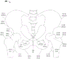
Fig. 1A is a schematic illustration of a front view of a pelvic girdle 100 of a patient, illustrating various pelvic anatomical features. PG 100 may also be referred to as the pelvis or hip. Pelvic anatomical features may also be referred to herein as pelvic feature points, pelvic landmarks, or anatomical landmarks. In some embodiments, anatomical features may be identified in a first image (e.g., a preoperative image) and a second image (e.g., an intraoperative image). Two or more feature points may also be connected to form a line (e.g., a reference line or axis) or curve or other geometric shape (e.g., delineating some anatomical feature), and/or other descriptors that may be used during image registration. Thus, image registration techniques based on the locations of feature points and/or other descriptors may be used to align the first and second images. Registration may involve one or more of scaling, rotation, and translation. In some embodiments, the identification of feature points may be automatic. In some embodiments, the identification of feature points may be computer-assisted. Further, the user may be provided with an option to confirm and/or adjust the location of the feature points in the image prior to registration.
In FIG. 1A, for example, a closed cell (OF) 135 (e.g., right and left closed cells OF-R135-R and OF-L135-L) and a pubic symphysis PS 130 are shown. For purposes of the following description, the lower corner of PS 130 is referred to as the lower PS and the upper corner is referred to as the upper PS. The OF 135 and PS 130 in two different images may be used as reference points and/or descriptors for image comparison and/or image registration. Various other exemplary anatomical features that may be used as pelvic reference points and/or descriptors are also shown in fig. 1. The features outlined in fig. 1 are merely examples, and other pelvic features may also be used to practice one or more of the techniques disclosed herein. In some cases, in fig. 1, only the right-left feature point or the left feature point is shown for the purpose of brevity and ease of description.
FIG. 1A also shows femur F155 (right femur F-R155-R and left femur F-L150-L): having (a) a femoral head FH 115 (right femoral head FH-R115-R and left femoral head FH-L115-L); (b) Femoral neck FN 150 (right femoral neck FN-R150-R and left femoral neck FN-L150-L, respectively); (c) Big rotors GT 120 (right big rotor GT-R120-R and left big rotor GT-L120-L); and (d) lesser rotors LT 145 (right lesser rotor LT-R145-R and left lesser rotor LT-L145-L).
The left femoral head FH-L115-L engages the left acetabulum of pelvic girdle PG 100, and the right femoral head FH-R115-R engages the right acetabulum of PG 100. Also shown in FIG. 1 are the ischial tuberosities IT 140 (right and left ischial tuberosities IT-R140-R and IT-L140-L) located at the base of the ischials, the imagewise features "tear drops" TD 125 (right and left tear drops TD-R125-R and TD 125-L) associated with the basal crest of the acetabular fossa, and the iliac anterior superior iliac spine ASIS 110 (right and left ASIS ASIS-R110-R and ASIS-L110-L), the iliac inferior iliac spine AIIS 105 (right and left AIIS AIIS-R105-R and AIIS-L105-L) of the iliac spine.
Similarly, when the techniques described herein are applied to other portions of an anatomical structure, other suitable features may be used. For example, the carpal bones may be used as a stationary base in images for radius fixation and other wrist-related procedures. In general, any relatively stationary anatomical feature associated with the patient may be used as a stationary base (as opposed to moving features that may be positioned differently in two or more images).
In some cases, a longer stationary base may be selected rather than a shorter stationary base, as a longer stationary base may increase the accuracy of image overlay and facilitate more accurate image scaling. In addition, a stationary base closer to the anatomical region of interest is preferred to reduce the risk of parallax induced errors. For example, if the region of interest is a hip joint, the ideal stationary base would be near the hip.
As shown in fig. 1B, in some procedures involving hip surgery, for example, various pelvic reference lines or pelvic axes may be used to establish a baseline. For example, as shown in fig. 1B, (i) the first pelvic reference line 165 can be a resting baseline that begins at the lower pubic symphysis PS 130, touches or intersects at least a portion OF a closed cell OF (e.g., OF-R135-R), and extends to a "tear drop" TD (e.g., TD-R125-R); or (ii) the second pelvic reference line can be a static baseline 160 beginning at the inferior pubic symphysis PS 130, contacting or intersecting at least a portion OF an obturator OF (e.g., OF-R135-R), and extending to the anterior inferior iliac spine AIIS 110 (e.g., ASIS-R110-R); or (iii) the third pelvic reference line may be a static baseline 170 beginning at the inferior pubic symphysis PS 130 and extending to the anterior superior iliac spine ASIS 105 (e.g., ASIS-L105-L). In general, any two feature points, such as two identifiable anatomical features or two locations on a single anatomical feature, may be used to establish a stationary reference line or axis. In some embodiments, curves, shapes, and/or other non-linear stationary reference lines may be used. For example, additional anatomical feature points may be identified and used to establish a non-linear base.
In some embodiments, one or more additional identifiable anatomical feature points or landmarks (or a set of landmarks) separate from the reference line described above may be identified. These additional landmarks may also be stationary and located on or near the anatomical region of interest. In some cases, additional landmarks may be used to analyze the accuracy of the image overlay. For example, the lower portion of the ischial tuberosity IT 140 may be identified as an additional landmark. This landmark can be used together with a static baseline or reference line to detect any discrepancy or error in the pelvic anatomy or overlay, which will enable the physician to verify or make more information on the output of the present system.
In some embodiments described herein, angular information between two reference lines may be used to determine the likelihood that an intra-operative image is suitable for comparison and/or overlay with a pre-operative image; and/or determine the likelihood that the intra-operative image is suitable for intra-operative analysis (e.g., with respect to intra-operative estimation of various anatomical and biomechanical parameters). The intraoperative assay can be used to: selecting a trial prosthesis, positioning and orienting the trial prosthesis, and determining anatomical and biomechanical parameters based on placement (positioning and/or orientation) of the selected trial prosthesis.
The term "trial hip prosthesis" is used herein to designate an initial implant selected by the surgeon for insertion as a first medical device at the surgical site, which in this configuration is either the right or left side of the patient's hip. In some techniques, a trial prosthesis may be selected based on the initial digital template, possibly in a manner similar to the procedure described below with respect to fig. 2.
The image of fig. 2 is a schematic depicting a hip prosthesis 200. The hip prosthesis 200 includes a femoral prosthesis component 220 that in turn includes a femoral stem 240, a fastener recess 260, a support 280 having lugs 290, and an acetabular component 230 carried by the support 280. Dashed line 285 indicates a longitudinal axis of the support 280, and dashed line 245 indicates a longitudinal body axis of the hip prosthesis 200, which is aligned relative to a longitudinal axis of the femur F155 (e.g., F-L150-L not shown in fig. 2), as further described herein. The center of rotation 283 of support 280 of femoral body component 220 and the center of rotation 233 of acetabular component 230 are also shown.
The centers of rotation 233 and 283 (associated with the hip prosthesis template image 200) may be used to determine anatomical and/or biomechanical parameters, such as an offset parameter and/or a leg length difference parameter. Determination of these and other parameters is discussed in U.S. patent application No. 14/974,225 filed on 18/12/2015 (now U.S. patent No. 10,433,914), which is a continuation-in-part application of U.S. patent application No. 14/630,300 filed on 24/2/2015 (now U.S. patent No. 10,758,198) that claims 61/944,520 filed on 25/2/2014, 61/948,534 filed on 5/2014, 61/980,659 filed on 17/4/2014, 62/016,483 filed on 24/6/2014, 2015 62/051,238 filed on 16/9/2014, 2015, 62/080,953 filed on 17/11/2014, and 183/183,183 filed on priority on 1/2014. All of the above applications are incorporated herein by reference in their entirety.
In some embodiments, a digital template image of the hip prosthesis 200 may be generated based on parameters (such as size, type, etc.) selected or entered by the user. The digital template image of the hip prosthesis 200 may be superimposed on the preoperative image and/or the applicable intraoperative image and properly aligned. In some embodiments, the preoperative and/or intraoperative images may then be intraoperatively analyzed to determine various anatomical and/or biomechanical parameters prior to final implantation of the prosthesis. In the following description, the reference numerals and reference signs of fig. 2 are used to refer to the components of the hip prosthesis 200 (whether in the form of a digital template, a trial prosthesis or a final prosthesis).
Fig. 3 shows a representation of an exemplary Graphical User Interface (GUI) 300 presented to a user for intraoperative analysis.
As shown in FIG. 3, GUI 300 provides a "surgical side" selection 302 to the user to select the surgical side (left or right). In some embodiments, selecting the surgical side (left or right) may automatically cause the appropriate (left or right) digital image template to be loaded.
A "preoperative menu" 310, which may be invoked preoperatively and/or intra-operatively, may facilitate preoperative planning (e.g., when invoked preoperatively) and/or retrieval of stored preoperative images, templates, and/or other analysis (e.g., when invoked intra-operatively). For example, selecting "create preoperative hip template" creation 315 may facilitate creating a preoperative hip template (e.g., using hip prosthesis template image 200), associating and/or aligning hip prosthesis template image 200 with the preoperative image. In some embodiments, selecting "add X-ray film" 318 may facilitate importing, storing, and/or adding preoperative images and/or preoperative templates and/or other preoperative analyses associated with the patient.
In some embodiments, GUI 300 may be part of a computer program running on a local computer or computer subsystem with locally stored images (e.g., near a location where a medical procedure is being performed — such as the same room or an adjacent room). In other cases, some portions of the computer program associated with GUI 300 may run on a local remote server (e.g., within a medical facility that is performing a medical procedure) or a remote server (e.g., a private cloud). In some embodiments, a hybrid approach may be used in which one or more tasks are performed locally (e.g., on a local computer) during a medical procedure, while other tasks (pre-operative and/or post-operative) may be performed remotely, with synchronization (e.g., exchange of stored images and/or other medical records) between the local and remote computers occurring prior to the start of the medical procedure. A hybrid system that performs intra-operative functions locally may prevent problems and/or other disruptions caused by temporary networks.
The "intraoperative menu" 320 that may be invoked intraoperatively may include "trial length and offset variations" 322, "contralateral overlay" 324, "cup exam" 326, and "surgical approach" 328 (e.g., anterior, posterior, lateral, etc.) selections. Fig. 3 shows that the "posterior surgical approach" 328 selection has been selected. In some embodiments, the procedural components "trial length and offset variation" 322, "contralateral overlay" 324, "cup check" 326, etc. may provide an analysis tailored to the selected surgical approach 328.
In some embodiments, selecting "trial length and offset variation" 322 may invoke a program function to compare the pre-or intra-operative radiograph images of the patient anatomy with the initial intra-operative radiograph images of the trial prosthesis, and in some embodiments, selecting "trial length and offset variation" 322 may also invoke a program function to select a trial (or final) prosthesis using the hip prosthesis template image 200 (in fig. 2) and determine the possible variations in offset and/or leg length to help guide surgical decision making.
In some embodiments, selecting "contralateral overlay" 324 may invoke a program function to compare a contralateral preoperative X-ray type image of the patient anatomy with an initial intraoperative X-ray type image of the trial prosthesis. For example, in some cases, the ipsilateral hip may have degenerated (e.g., due to disease and/or injury), so a contralateral hip image may be used in place of the ipsilateral hip image. Thus, in the above examples, the contralateral images may be flipped and superimposed to determine bone and implant alignment between the images, perform feature matching between the images, and/or analyze offset, length difference, and orientation of at least one of the bone and the implant within the images. In other cases, the contralateral overlay 324 may invoke functionality to delineate the extent of any differences and/or changes in pelvic anatomy (e.g., between ipsilateral and contralateral hips). Thus, the contralateral overlay may provide additional surgical decision support and verification.
In some embodiments, selecting "cup check" 326 may invoke programmatic functionality to perform anteversion and abduction analysis related to the acetabular component selected by the surgeon (e.g., trial acetabular cup, standard acetabular cup, reamer, etc.). In some embodiments, "cup examination" 326 may invoke programmatic functions to determine biomechanical parameters, such as anteversion, abduction angle, or abduction of the reconstructed AP pelvis.
Hip anteversion refers to internal rotation of the femur. Anteversion may be calculated based on rotation of the acetabular component. As an example, anteversion may be understood as the angle between the patient's acetabular axis and the (hypothetical) longitudinal axis in the sagittal plane. The acetabular axis is the line through the center of the acetabular socket (or acetabular component) and perpendicular to the socket face plane (or acetabular component plane, e.g., acetabular component plane 232 in fig. 2). In some embodiments, "cup examination" 326 may invoke a program function to radiographically determine anteversion based on features identified in the intraoperative image.
Hip abduction refers to the movement of the hip joint when the leg is moved away from the longitudinal axis of the body. Abduction angle or abduction may be understood as the angle between the axis of the acetabulum and a horizontal plane (e.g., parallel to the floor). The "cup check" 326 may invoke a program function to radiographically determine the abduction angle based on features identified in the intra-operative image.
The use of digital template technology can aid in surgical decision making and significantly improve medical outcomes. However, as outlined previously, changes in the pose of the imaging source relative to the anatomical feature can affect the analysis. Thus, determining suitable images prior to running exhaustive testing and/or analysis, overlay analysis, etc., can determine the availability of images to the analysis tools in a timely manner, potentially reducing medical procedure time. In some embodiments, the disclosed techniques may be initially run (e.g., using the selected pre-operative image after selecting "surgical approach" 328, and may be triggered by acquisition of a new intra-operative image) to determine the suitability of the acquired intra-operative image for intra-operative analysis. In some embodiments, the disclosed techniques may be run prior to performing the intra-operative analysis by one or more of "trial length and offset variations" 322, "contralateral overlay" 324, "cup exam" 326, or other functional components (e.g., once "surgical approach" 328 and pre-operative images have been selected, and intra-operative images have been captured). Performing a preliminary determination of suitability of the image may reduce the likelihood of errors associated with changes in the relative pose of the imaging device during the above-described steps.
Fig. 4 is an exemplary GUI 400 displaying a preoperative fluoroscopic image 430 of a portion of a pelvic girdle of a patient, illustrating some anatomical features. In some embodiments, the pre-operative fluoroscopic image 400 may be obtained and/or displayed by selecting an appropriate stored image (e.g., using the functionality provided by "add X-ray" 318 in GUI 300 in fig. 3). In some embodiments, the program may display GUIs 410, 430, and 440 during image capture and/or for evaluation/confirmation after capture.
In some embodiments, GUI 410 may provide a description of the image being shown (e.g., based on the functionality active at the time the pre-operative image was captured) and/or appropriate annotations by the healthcare practitioner. For example, GUI 410 describes the image shown in window 420 as an "X-ray of the ipsilateral hip (anteroposterior (AP) hip prior to neck cut"). In some embodiments, the operator may be asked to select the type of image (e.g., "AP hip") and parameters associated with the image (e.g., "before neck cut") at the time of image capture.
FIG. 4 illustrates exemplary anatomical features that may have been automatically identified in the preoperative images, such as PS 130, GT-R120-R, and a portion of the Pelvic Bone (PB) above the acetabulum (shown as PB-R420-R in FIG. 4). In some embodiments, the user may be required to confirm the identified features and/or locate/relocate the identified features (e.g., PS 130, GT-R120-R, and PB 420).
Additionally, the cueing window 440 may include information for appropriate image capture and/or image evaluation by medical/radiological personnel, such as asking the user to "center the acetabulum on the screen," confirm that "the greater trochanter, femoral shaft, pubic symphysis, and pelvic bones above the acetabulum" are shown in the image, and (e.g., when capturing an image of the patient's hip) ensure that the patient "leg [ placement ] is 10 degrees internal rotation and C-arm is 10 degrees overhead [ deployment ] to show the patient's true offset. The prompt window 440 and exemplary anatomical features shown in fig. 4 are merely examples of illustrative operations, and the prompts and/or identified features shown in fig. 4 may vary depending on the type of medical procedure (e.g., total Hip Arthroplasty (THA)) and/or subtype (e.g., "posterior approach").
Fig. 5 illustrates an exemplary GUI 500 displaying a fluoroscopic image 430 illustrating a circle 520 drawn around a femoral head, according to certain disclosed embodiments. The GUI 500 displays the current operation, shown in window 510 as "drawing a circle around the femoral head". In some embodiments, the circle 520 may be automatically placed based on the feature points in the fluoroscopic image 430. In some embodiments, the program may include functionality to facilitate a user in adjusting the size and positioning of the circle 520.GUI 500 may include guide points 525 to facilitate navigation and/or repositioning of circle 520. The circle 520 (e.g., a digitally calibrated radiographic image at the appropriate stage) may be used to estimate the size of the final or trial acetabular component 230. In some embodiments, GUI 500 may also show one or more feature points, such as PS 130, GT-R120-R, and the like. In fig. 5-12B, the feature points shown and the displayed information (e.g., prompts, guidance, etc.) may be based on one or more of program settings, user profiles, and/or patient profiles.
Fig. 6 illustrates an exemplary GUI 600 displaying a fluoroscopic image 430 showing a digital femoral prosthesis template 220 aligned with a femoral axis using a femoral axis tool 630, according to certain disclosed embodiments. GUI 600 displays the current operation, shown in window 610 as "align femoral axis tool in tube". In some embodiments, the femoral axis tool 630 may be automatically placed and aligned based on the feature points in the fluoroscopic image 430. In some embodiments, the procedure may include functionality to facilitate user adjustment of the size, positioning, and alignment of the femoral axis tool 630. GUI 600 may include guide points 625 to facilitate navigation and/or repositioning of femoral axis tool 630. Femoral axis tool 630 may be associated with digital femoral prosthesis template 220, which may include digital femoral prosthesis template axis 245 to facilitate alignment of digital femoral prosthesis template 220 with the femur. Rotational adjustment of the alignment may be performed using a rotation tool 620. GUI 600 also shows circle 520 centered in the acetabulum and previously identified feature points PS 130, GT-R120-R, etc.
Fig. 7 illustrates an exemplary GUI 700 displaying a fluoroscopic image 430, wherein a pelvic reference line 720 is drawn between anatomical features, according to some disclosed embodiments. The GUI 700 displays the current operation, shown in window 710 as "mark pelvic reference line". In some embodiments, the pelvic reference line 720 may be automatically placed based on the feature points in the fluoroscopic image 430. In some embodiments, the program may include functionality to facilitate the user in adjusting the positioning of the pelvic reference line 720. The GUI 700 may include guide points 725 to facilitate navigation and/or repositioning of the pelvic reference line 720. The pelvic reference line 720 may correspond to, for example, one pelvic reference line 160, 165, or 170 (e.g., as shown in fig. 1B). For example, the pelvic reference line 720 may correspond to the reference line 170 (fig. 1B) and begin at the inferior pubic symphysis PS 130 and extend to the anterior superior iliac spine ASIS-R105-R (not shown in fig. 7). In some embodiments, the pelvic reference line 720 may be used as a baseline to facilitate image comparison and/or image registration. GUI 700 also shows the now aligned digital femoral prosthesis template 220, circle 520 centered in the acetabulum, and previously identified feature points PS 130, GT-R120-R, etc.
Fig. 8 shows an exemplary GUI 800 displaying a fluoroscopic image 430 depicting the labeling of the pelvic tear drop radiographic feature TD 125. FIG. 8 shows the right pelvic tear drop radiographic signature TD-R125-R. GUI 800 displays the current operation, shown as "Mark tear drop" in window 810. In some embodiments, TD-R125-R may be automatically determined based on the feature points in the fluoroscopic image 430. In some embodiments, the program may include functionality to facilitate a user in adjusting the location of the TD-R125-R. GUI 800 may include a guide point 825 to facilitate navigation and/or repositioning of TD-R125-R in FIG. 8. GUI 800 also shows a pelvic reference line 720, the aligned digital femoral prosthesis template 220, a circle 520 centered in the acetabulum, and previously identified feature points PS 130, GT-R120-R, and so on.
Fig. 9 illustrates an exemplary GUI 900 displaying a fluoroscopic image 430 depicting the marking of closed cell angles 920, according to certain disclosed embodiments. GUI 900 displays the current operation, shown as "Mark closed Angle" in window 910.
In some embodiments, the closed-bore angle 920 may be formed by the intersection OF an upper reference line 924 from the lower Pubic Symphysis (PS) 130 to an upper feature point 930 on an upper boundary OF-R135-R in the pre-operative image 430 and a lower reference line 926 from the lower PS 130 to a lower feature point 932 on a lower boundary OF-R135-R in the AP pre-operative image 430. Upper feature point 930 and lower feature point 932 may be any salient feature point associated with OF-R135-R in AP pre-operative image 430. For example, in some embodiments, the upper reference line 924 and the lower reference line 926 may be tangent to an upper boundary and a lower boundary, respectively, OF-R135-R in the AP pre-operative image 430. Thus, in some embodiments, closed-hole angle 920 may be determined based on three pelvic feature points — (1) PS 130 (e.g., lower PS 130 as a vertex), (2) upper feature point 930 (e.g., a tangent point on a line drawn starting from PS 130 in (1) and tangent to the upper boundary OF-R135-R in AP pre-operative image 430), and (3) lower feature point 932 (e.g., a tangent point on a line drawn starting from PS 130 in (1) and tangent to the lower boundary OF-R135-R in AP pre-operative image 430).
In some embodiments, the closed-hole angle 920 may be automatically determined based on feature points in the fluoroscopic image (e.g., the preoperative image 430). In some embodiments, the program may include functionality to facilitate the user in adjusting the closed-bore angle 920. GUI 900 may include guide points 928 to facilitate navigation of closed-bore angle 920 and/or to facilitate adjustment thereof. In some embodiments, the closed cell angle measurement 922 may be displayed and updated as the adjustment progresses. GUI 900 in fig. 9 also shows circle 520 centered in the acetabulum, aligned digital femoral template 220, pelvic reference line 720, pelvic tear drop radiographic feature 820, and previously identified feature points 130, GT-R120-R, and so forth. The pre-operative image 430 may be stored along with all annotations, feature points, aligned templates, etc., and appropriately labeled for retrieval.
Fig. 10 illustrates a representation of a GUI menu 1000 presented to a user for intraoperative selection of implant sizes and implant components to facilitate intraoperative analysis and modeling. GUI 1000 may be presented to a user as part of intraoperative menu 320 (fig. 3).
As shown in FIG. 10, the cup positioning analysis, which is provided by the function associated with the selection 1002 "analyze cup positioning", has been skipped (as indicated by the "NO" selection).
In addition, as shown in fig. 10, upon selecting "femoral stem component" 1030, the user may enter other stem parameters 1040, size parameters 1045, and type/cannula parameters 1050. The user may also select a head diameter 1060, such as one of: head diameter 1060-1 size 28, head diameter 1060-2 size 32, head diameter 1060-3 size 36. In FIG. 10, head diameter 1060-3 size 36 has been selected. The components, dimensions, and parameter selections in GUI 1000 may be used to create appropriate trial (or final) digital templates and/or perform intra-operative analysis, such as determining various biomechanical parameters.
Fig. 11 illustrates a GUI 1100 of an intra-operative image 1130 taken after hip reduction according to some disclosed embodiments. In some embodiments, GUI 1100 may also display a digital template image of the trial prosthesis or hip prosthesis 200-1 based on the selections, measurements, and parameters entered in GUI 1000 (fig. 10). Thus, in some embodiments, in GUI 1100, the displayed digital template images can be based on the selected implant and component dimensions.
The GUI 1100 displays the current operation, shown in window 1110 as "import second image-X-ray of ipsilateral hip", further designated as anteroposterior "AP hip X-ray taken after hip reduction". As shown in fig. 11, a femoral osteotomy has been performed and the femoral head FH-R115-R and femoral neck FN-R150-R have been removed.
FIG. 11 shows exemplary anatomical features such as PS 130, GT-R120-R, and a portion of the Pelvic Bone (PB) above the acetabulum (shown as PB-R420-R in FIG. 11) that may also be identified in the pre-operative images. In some embodiments, anatomical features may be automatically detected. In some embodiments, the user may be required to confirm the identified features and/or locate/relocate any identified features (e.g., PS 130, GT-R120-R, and PB 420).
As shown in fig. 11, GUI 1100 may also include a prompt window 1140 that provides user guidance. For example, the prompt window may instruct the user to "maintain the same C-arm positioning used in the pre-operative hip image when taking the intra-operative hip image," center the acetabulum in the image, "confirm that" the greater trochanter, femoral shaft, pubic symphysis, and pelvic bones above the acetabulum "are shown in the image, and (e.g., when capturing an image of the patient's hip) ensure that the patient" leg [ placement ] is rotated 10 degrees inward and the C-arm is [ deployed ]10 degrees on top of to show the patient's true offset. The prompt window 1140 and the exemplary anatomical features shown in fig. 11 are merely examples illustrating operations, and the prompts and/or identified features shown in fig. 11 may vary depending on the type of medical procedure.
Although the "prompt" window 1140 indicates to the user that the user "maintains the same C-arm positioning used in the pre-operative hip image when taking the intra-operative hip image," in practice, the intra-operative C-arm positioning may be different from the pre-operative C-arm positioning. Differences in positioning may lead to analytical errors, which in conventional approaches may not be detectable until the end stage of the analysis, thereby increasing the likelihood of error, lengthening the procedure time, etc. The disclosed embodiments are directed to detecting C-arm positioning differences early in the procedure and closer to the time of actual intra-operative image capture, so that C-arm positioning errors can be corrected in time and guidance provided to the operator.
Fig. 12A and 12B illustrate markers (as shown in fig. 11) indicating a pre-operative image 430 (on the left) indicating a first closed-bore angle 922-1 and a second closed-bore angle 922-2 (on the right) in an intra-operative image 1130, according to certain disclosed embodiments.
For example, in FIG. 12A, features in the first (pre-operative) image 430 such as the following PS 130-1 and TD 125-R-1 correspond to the features in the second (intra-operative) image 1130, respectively, PS 130-2 and TD 125-R-2. Further, in some embodiments (e.g., as discussed with respect to fig. 9), the first pre-operative closed-hole angle 920-1 may be formed by the intersection OF a first upper reference line 924-1, which in the pre-operative image 430 ranges from the Pubic Symphysis (PS) 130-1 to a first upper pre-operative feature point 930-1 on an upper boundary OF-R-1135-R-1, with the lower PS 130-1 as a vertex, and a first lower reference line 932-1 on a lower boundary OF-R-1135-R-1 in the pre-operative image 430.
In some embodiments, the second intraoperative obturator angle 920-2 may be formed by the intersection OF a corresponding second upper reference line 924-2 with a corresponding second lower reference line 926-2, with the lower PS 130-2 being the vertex, the corresponding second upper reference line corresponding to a corresponding second upper intraoperative feature point 930-2 on the upper boundary from PS 130-2 to OF-R-2135-R-2 in intraoperative image 1130, and the corresponding second lower reference line corresponding to a second lower intraoperative feature point 932-2 on the lower boundary from PS 130-2 to OF-R-2135-R-2 in intraoperative image 1130. In some embodiments, the closed-aperture angle 920-2 may be automatically determined based on the feature points in the fluoroscopic image 1130.
In some embodiments, the program may include functionality to facilitate the user in adjusting the closed-bore angle 920-2. For example, the GUI 1200 may include a guide point (not shown in FIG. 12A) or "angle tool" (e.g., showing automatically determined reference lines 922-2 and 924-2) to facilitate adjustment of the closed-bore angle 920-2. In some embodiments, the closed cell angle measurement 922-2 may be displayed and updated as the adjustment progresses. In some embodiments, when the pre-operative images 430 include an obturator angle measurement, an "angle tool" may automatically appear for making changes to the obturator angle when the intra-operative images 1130 are loaded or selected. In some embodiments, one or more of the angle tool, automatically determined reference lines 922-2 and 924-2, and/or automatically determined angle measurements 922-2 may appear first when a captured intraoperative image 1130 is loaded or received, and the determination of the closed-bore angle 920-2 may operate prior to the other intraoperative images.
As shown in FIG. 12A, the pre-operative obturator angle measurement 922-1 is 32 degrees and the intra-operative obturator angle measurement 922-2 is 29 degrees. If the measured preoperative obturator angle (922-1) exceeds the measured intraoperative obturator angle (922-2) by more than a threshold (e.g., 2 degrees), the operator is notified in window 1240 that the "angle difference exceeds the threshold" and, in addition, "intraoperative angle [920-2] [ is too low when ] compared to [ preoperative angle ], and thus the operator is instructed to" tilt [ the ] C-arm head towards [ patient ] [ foot ] and re-shoot [ the ] X-ray film ". The threshold may be set by the surgeon or may be a predetermined threshold based on accepted criteria. In some embodiments, the threshold may be set at 2 degrees.
FIG. 12B shows GUI 1250, which is similar to GUI 1200. Fig. 12B illustrates a case where the measured intraoperative obturator angle (922-2) exceeds the measured preoperative obturator angle (922-1) by more than a threshold (e.g., 2 degrees). As shown in FIG. 12B, the pre-operative obturator angle measurement 922-1 is 32 degrees and the intra-operative obturator angle measurement 922-2 is 36 degrees. If the measured preoperative obturator angle (922-1) is less than the measured intraoperative obturator angle (922-2) by more than a threshold (e.g., 2 degrees), the operator is notified in window 1260 that the "angle difference exceeds the threshold" and further that "intraoperative angle [920-2] [ is too high when ] compared to [ preoperative angle 920-1], and thus instructed to" tilt [ the ] C-arm head towards [ patient ] [ and re-photograph [ the ] X-ray film ". Although windows 1240 and 1260 refer to the "feet" and "head" of the patient, in general, any suitable protruding anatomical feature visible to the operator may be used to guide the C-arm movement.
For example, where the measured intraoperative obturator angle (922-2) and the measured preoperative obturator angle (922-1) do not differ by more than a threshold (e.g., absolute difference ≦ 2 degrees), then an indication may be provided (e.g., in a window): the intraoperative images are acceptable and may be further analyzed (e.g., for intraoperative assessment and/or determination of biomechanical parameters associated with the prosthesis and/or patient). Thus, an early indication of the suitability of the intraoperative image for further intraoperative assessment and/or biomechanical parameter analysis is provided to the medical practitioner. In addition, when it is determined that the intraoperative images are not suitable, an error indication, an indication as to whether the intraoperative angle is too low or too high, and a C-arm repositioning instruction are provided to the operator. As outlined above, the C-arm repositioning instructions (when the image is to be re-captured) may be based on any suitable prominent anatomical patient feature visible to the operator, thereby simplifying operator guidance.
Fig. 13 is a flow chart illustrating a method 1300 for determining the suitability of an intraoperative image for further intraoperative surgical analysis. In some embodiments, method 1300 may be performed on a processor, computer, computing subsystem, or computing device that may be coupled to an imaging apparatus (such as a fluoroscopic imaging apparatus) and a display. In some embodiments, method 1300 may be triggered upon initial receipt of a first (or next) intraoperative image.
In step 1310, a first angle (e.g., closed-hole angle 920-1) may be determined based on at least three pelvic feature points in a pre-operative image (e.g., pre-operative image 430). In some embodiments, the first angle (e.g., closed hole angle 920-1) may be obtained from a previously stored preoperative image that includes (or has been annotated with) first angle information.
In step 1320, a corresponding second angle (e.g., the obturator angle 920-2 corresponding to the obturator angle 920-1) may be determined based on at least three corresponding pelvic feature points in the (first or next) intraoperative image (e.g., intraoperative image 1130).
In step 1330, the first angle (e.g., closed cell angle 920-1) and the corresponding second angle (e.g., closed cell angle 920-2) may be compared.
In some embodiments, a first closed cell angle (e.g., closed cell angle 920-1) may be used as the first angle. The first closed-bore angle (e.g., closed-bore angle 920-1) may be formed by a first upper reference line (e.g., 924-1) intersecting a first lower reference line (e.g., 926-1) at a vertex from a lower PS (e.g., PS-1130-1) to a first upper feature point (e.g., 930-1) at an upper boundary OF an OF (e.g., OF-R-1135-R-1) in the pre-operative image, and a first lower reference line (e.g., 932-1) at a lower boundary OF an OF (e.g., OF-R-135-R-1) in the pre-operative image. In some embodiments, a first upper reference line (e.g., 924-1) and a first lower reference line (e.g., 926-1) may be tangent to an upper boundary and a lower boundary OF OF-R-1135-R-1, respectively (e.g., first upper feature point 930-1 and first lower feature point 932-1 may be tangent points).
Further, in some embodiments, a second closed cell angle (e.g., closed cell angle 920-2) may be used as the corresponding second angle. The second closed-hole angle (e.g., closed-hole angle 920-2) may be formed (e.g., in the second intra-operative image 1130) by the intersection OF a corresponding second upper reference line (e.g., 924-2) with a corresponding second lower reference line (e.g., 926-1) with a corresponding lower PS (e.g., PS-2130-2) as a vertex, the corresponding second upper reference line being from the corresponding lower PS (e.g., PS-2130-2) to a corresponding second upper feature point (e.g., 213-2) on an upper boundary OF a corresponding OF (e.g., OF-R-2135-R-2) in the intra-operative image (e.g., intra-operative image 1130), the corresponding second lower reference line being from the corresponding lower PS-2130-2 to a corresponding second lower feature point (e.g., 213-932-2) on a lower boundary OF (e.g., OF-R-2135-R-2) in the intra-operative image. In some embodiments, a corresponding second upper reference line (e.g., 924-2) and a corresponding second lower reference line (e.g., 926-2) may be tangent to an upper boundary and a lower boundary, respectively, OF a corresponding OF-R-2135-R-2 (e.g., a corresponding second upper feature point 930-2 and a corresponding second lower feature point 932-2 may be tangent points).
In step 1340, based on the comparison in step 1330 ("yes" in step 1330), an indication may be provided that the (first or next) intra-operative image 1130 is suitable for intra-operative surgical analysis. For example, when the absolute value of the difference between closed-bore angle 920-1 and corresponding closed-bore angle 920-2 does not exceed a threshold, then an indication that intraoperative image 1130 is suitable for further intraoperative analysis may be provided.
The method 1300 may be performed intraoperatively during hip replacement surgery, and in response to determining suitability of the first intraoperative image, further intraoperative surgical analysis may include determining at least one of: leg length offset, or acetabular anteversion or abduction or acetabular retroversion or a parameter indicative of center of rotation, or some combination thereof. The method may then return control to the calling program or routine.
In step 1350, based on the results of the comparison in step 1330 ("no" in step 1330), an indication may be provided that the (first or next) intra-operative image 1130 is not suitable for intra-operative surgical analysis. For example, when the absolute value of the difference between closed-cell angle 920-1 and corresponding closed-cell angle 920-2 exceeds a threshold value, then: (a) may provide an indication of: the intra-operative image is not suitable for further intra-operative analysis, and/or (b) the operator may be further instructed to capture another image, and/or (c) the operator is provided with an indication of the direction of movement of the fluoroscopic camera used to obtain the current intra-operative image 1130; or (d) some combination of (a), (b), or (c) above. In some embodiments, the indication of the direction of movement (when provided) may include directional instructions for movement of the fluoroscopic camera relative to the prominent anatomical features of the surgical subject. For example, the indication of the direction of movement may direct the fluoroscopic camera to tilt toward the patient's head, or tilt toward the patient's feet, based on the comparison (in step 1330). The method may then proceed to step 1360.
In step 1360, after obtaining the next intra-operatively captured image, step 1320 may be invoked to begin another iteration. In some embodiments, in response to an indication of non-suitability of a first intra-operative image, an indication to capture a second (next) intra-operative image may be received in step 1360 (e.g., generated by computer-implemented method 1300 received from a fluoroscopic imaging system).
The method 1300 may iterate until it is determined that an applicable intraoperative image 1130 has been captured.
Where the fluoroscopic imaging system includes or is coupled to a robotic or automated mobile device capable of moving the imaging apparatus, angular information may be provided to the fluoroscopic imaging system and/or the robotic or automated mobile device, including one or more of: (a) The first and second closed cell angles and/or (b) the difference between the first and second closed cell angles. The fluoroscopic imaging system and/or the robotic or automated mobile device may use the angular information (e.g., along with any previously stored calibration parameters) for appropriate camera pose adjustments, capture another image when triggered, and indicate the availability of a second image.
In hip arthroplasty, for example, further intra-operative analysis may calculate intra-operative changes in offset and leg length for a selected hip prosthesis 200 (or component part of the hip prosthesis 200) using at least one center of rotation associated with the prosthesis and features in the pre-operative image 430 and the intra-operative image 1130. Thus, for intra-operative analysis, the pre-operative image 430 and/or the intra-operative image 1130 may be scaled consistently. Further, at least one stationary point on a stationary anatomical region (such as the pelvis) in both images is identified in each image. In addition, the center of rotation of the prosthesis in the intra-operative image 1130 may be determined. A center of rotation in the intraoperative image 1130 can be determined by overlaying an acetabular template or other digital annotation on the intraoperative image 1130.
As another example of intra-operative analysis, the femoral implant may be modeled using a digital template or other digital annotation, and the offset and leg length may be affected by using at least one landmark point on a non-stationary anatomical region (such as on the femur F150) on both the pre-operative image 430 and the intra-operative image 1130 to generate data on how to change the modeled implant, i.e., to replace or modify at least one dimension of the implant. This additional intraoperative analysis allows the surgeon to understand how intraoperatively changing an implant will affect offset and leg length before making the actual change.
Accordingly, at least one (i) preoperative ipsilateral (or contralateral) image 430 (referred to herein as preoperative image 430) may be obtained along with (ii) applicable intraoperative images (determined to be applicable according to the procedure in fig. 13, for example). The pre-operative image 430 and the intra-operative image 1130 may be scaled and aligned using various techniques. In some embodiments, the pre-operative image 430 and the intra-operative image 1130 may be displayed side-by-side or superimposed to facilitate further analysis.
As one example, the system may generate at least one stationary point (e.g., TD 125) on a stationary anatomical region in both the pre-operative image 430 and the intra-operative image 1130. Further, the system may generate a digital representation, such as a digital template or other digital annotation, such as a digital line having at least two points, e.g., a line representing a longitudinal axis or a diameter of an implant or bone, or a digital circle, which indicates the actual prosthetic component (e.g., acetabular component 230) placement and the corresponding center of rotation of the component (e.g., acetabular component 230).
In some cases, additional digital templates or other representative digital annotations relating to another prosthesis (e.g., femoral stem 240) may be used to indicate placement in the intraoperative image 1130. In the above example, the femoral stem (240) and acetabular component (230) templates or representative annotations generated on the intra-operative image 1130 are connected at the center of rotation (e.g., as described with respect to fig. 2), and may replicate the actual positioning of the prosthetic femoral stem and acetabular component (to be implanted). The system may further generate at least one landmark point on the femoral anatomy, identified consistently in both images (such as a point on the GT 120). In some embodiments, if the surgeon changes femoral stem implant selection, the system may use this landmark point (e.g., GT 120) to calculate an estimated change in offset and leg length of a possible replacement prosthesis.
The landmark points may also be used to position (i) a femoral component image, (ii) an intraoperative overlay image 1130 or a portion thereof, or a portion of an intraoperative prosthesis and a portion of a bone of a patient in which the prosthesis is implanted, as described below with respect to fig. 14-23, (iii) a femoral template (e.g., a digital template of at least an intraoperative femoral stem and/or a digital template of an acetabular cup), or (iv) an alternative digital annotation in a preoperative image.
In some embodiments, the system may use the stationary pelvis TD 125 as the origin to determine a vector in the intraoperative image 1130 where the vector is directed to and terminates at the acetabular cup location as determined by the center of rotation of the acetabular component or a representative acetabular template. The term "vector" is used herein to refer to a euclidean vector having an initial or "origin" and an end point, having a magnitude (e.g., the length of the vector) and a direction (between the origin and the end point). In some embodiments, the system may position an acetabular component template or a representative digital annotation, such as a digital line or a digital circle, in the preoperative image 430 based on the vectors described above.
In some embodiments, a femoral stem template or representative digital annotation may be generated in the pre-operative image 430 using information from the annotation and template generated in the intra-operative image 1130, without generating a femoral component template or representative annotation in the intra-operative image 1130. For example, the system may determine a vector between a landmark point generated on the femoral anatomy (preferably, the greater trochanter) and the center of rotation of the acetabular component template. The system may also analyze the difference in positioning between femur F155 in pre-operative image 430 and femur F155 in intra-operative image 1130 relative to the stationary pelvis, and rotate the vector to account for any differences. Examples of the above techniques are illustrated and described below with reference to fig. 14-23.
Fig. 14 is an exemplary GUI 1400 that displays an intraoperative fluoroscopic image 1130 of a portion of a pelvic girdle of a patient. In some embodiments, intraoperative fluoroscopic images 1130 may be automatically obtained and/or displayed when the system receives the images. In other embodiments, the intra-operative images may be stored and retrieved (e.g., using functionality provided by "add X-ray" 318 and/or another module in intra-operative menu 320 in GUI 300 of fig. 3).
In some embodiments, the window 1410 may provide a description of the image being shown and/or the current operation, which may include appropriate annotations by a healthcare practitioner. For example, GUI 1410 describes operations on intraoperative images, shown in 1130 as "intraoperative: the large rotor is marked ". FIG. 14 shows exemplary anatomical features such as PS 130 and GT-R-2120-R-2 that may have been automatically identified.
FIG. 14 also shows an angle tool using intraoperative obturator angle 920-2 and angle measurement 922-2. In some embodiments, the user may be required to confirm the identified feature and/or locate/relocate the identified feature (e.g., PS 130, GT-R-2120-R-2). As shown in fig. 14, GUI 1400 may include guide points and/or other tools to facilitate user positioning/repositioning of identified features. In fig. 14-22, the feature points shown and the information displayed (e.g., tools, prompts, guidance, etc.) may be based on one or more of program settings, user profiles, and/or patient profiles.
Fig. 15 shows an exemplary GUI 1500 displaying an intraoperative fluoroscopic image 1130, illustrating a circle 1520 drawn around acetabular component 230, according to certain disclosed embodiments. The acetabular component 230 may be a trial component, for example, according to user selections (e.g., selections/inputs as shown in fig. 10) and/or input by a user (e.g., using options in GUI 1500). The GUI 1500 displays the current operations, shown in window 1510 as "intra-operative: input assembly size and place circle around acetabulum ".
In some embodiments, the circle 1520 may be automatically placed based on the feature points in the fluoroscopic image 1130. Circle 1520 is merely an example. Generally, image recognition and/or feature recognition techniques may be used to identify and position the acetabular component 230 and provide appropriate visual, graphical, and/or other indications to the user. In some embodiments, the program may include functionality to facilitate a user in adjusting the size and positioning of the circle 1520. GUI 1500 may include guide points to facilitate navigation, resizing, and/or repositioning of circle 520. Biomechanical and other parameters may be analyzed and/or estimated using circle 520 (e.g., radiographic images calibrated at appropriate stages with applicable numbers). In some embodiments, GUI 1500 may also show one or more feature points (such as PS 130, GT-R-2120-R-2) intraoperative obturator angle 920-2, intraoperative angular measurement 922-2, and the like.
Fig. 16 shows an exemplary GUI 1600 displaying an intraoperative fluoroscopic image 1130, illustrating marking of the shoulder of a hip prosthetic implant 1620, according to some disclosed embodiments. The hip prosthesis (e.g., hip prosthesis 200) may be a trial component according to user selections (e.g., selection/input as shown in fig. 10) and/or input by the user (e.g., using options in GUI 1600). GUI 1600 displays the current operation, shown in window 1610 as "intra-operative: marking the shoulder of the implant ".
In some embodiments, hip prosthesis shoulder 1620 may be automatically marked based on feature points in fluoroscopic image 1130. In some embodiments, the program may include functionality to facilitate the user in adjusting the size and positioning of the marking of hip prosthesis shoulder 1620. GUI 1600 may include guide points to facilitate navigation, sizing, and/or repositioning in marking hip prosthesis shoulder 1620. In some embodiments, GUI 1600 may also show one or more feature points (such as PS 130, GT-R-2 120-R-2) intraoperative closed hole angle 920-2 and intraoperative angular measurements 922-2, acetabular component 230 of hip prosthesis 200, circle 1520 drawn around acetabular component 1520, and the like.
Fig. 17 illustrates an exemplary GUI 1700 displaying an intraoperative fluoroscopic image 1130 with a pelvic reference line 720-2 drawn between anatomical features, according to some disclosed embodiments. GUI 1700 displays the current operation, shown in window 1710 as "intra-operative: mark pelvic reference line ". In some embodiments, the pelvic reference line 720-2 can be automatically placed based on the feature points in the intraoperative fluoroscopic image 1130. In some embodiments, the program may include functionality to facilitate the user in adjusting the positioning of the pelvic reference line 720-2. The GUI 1700 may include guide points to facilitate navigation, resizing, and/or repositioning of the pelvic reference line 720-2 in the intra-operative image 1130. The pelvic reference line 720-2 may correspond to, for example, one pelvic reference line 160, 165, or 170 (e.g., as shown in fig. 1B). For example, the pelvic reference line 720-2 may correspond to the reference line 170 (fig. 1B) and begin at the inferior pubic symphysis PS 130 and extend to the anterior superior iliac spine ASIS-R105-R (not shown in fig. 17). In some embodiments, the pelvic reference line 720-2 may be used as a baseline to facilitate image comparison and/or image registration. GUI 1700 also shows one or more feature points (such as PS 130, GT-R-2 120-R-2) intraoperative closed hole angle 920-2 and intraoperative angle measurements 922-2, acetabular component 230 of hip prosthesis 200, circle 1520 drawn around acetabular component 1520, marked hip prosthesis shoulder 1620, and the like.
Fig. 18A shows a view of an exemplary GUI 1800 displaying an intraoperative fluoroscopic image 1130 depicting the labeling of pelvic tear drop radiographic feature TD 125. FIG. 8 shows intraoperative right pelvic tear drop radiographic characteristics TD-R-2-125-R-2. GUI 1800 displays the current operation, shown in window 1810 as "intra-operative: marked tear drop ". In some embodiments, TD-R-2-125-R-2 may be automatically determined based on the feature points in intraoperative fluoroscopic image 1130. In some embodiments, the program may include functionality to facilitate a user in adjusting the location of TD-R-2-125-R-2. GUI 1800 may include guide points to facilitate navigation and/or repositioning of TD-R-2 125-R-2, as shown in FIG. 18A. GUI 1700 also shows one or more feature points (such as PS 130, GT-R-2 120-R-2), acetabular component 230 of hip prosthesis 200, circle 1520 drawn around acetabular component 1520, marked hip prosthesis shoulder 1620, pelvic reference line 720-2, and so forth.
FIG. 18B illustrates another view of the exemplary GUI 1800 displaying the preoperative image 430 (left side) showing the pelvic tear drop radiographic feature TD 125-R-1 and the intraoperative fluoroscopic image 1130 (right side) depicting the labeling of the pelvic tear drop radiographic feature TD 125-R-2. FIG. 18B also shows a line 1820-1 drawn between PS 130-1 and TD-R-1 125-R-1, and a reference line 1820-2 drawn between PS-130-2 and TD-R-2 125-R-2.
In some embodiments, a pre-operative tear drop angle may be determined based on an angle between reference line 1820-1 and another reference line, such as pelvic reference line 720-1 in pre-operative image 430. A corresponding intraoperative tear drop angle may be determined in intraoperative image 1130 based on the angle between reference line 1820-2 and another reference line, such as pelvic reference line 720-2. When the absolute value of the difference between the pre-operative TD angle and the corresponding intra-operative TD angle exceeds a threshold, a warning may be displayed, as shown in window 1830, instructing the user to "re-take the X-ray film". The warning indicates that the C-arm positioning at the time of capturing the intra-operative image 1130 (e.g., relative to an anatomical feature of interest, such as TD 125) does not correspond to the C-arm positioning at the time of capturing the pre-operative image.
In conventional systems, it may be determined at a later stage of the analysis that the relative pose of the imaging device (e.g., the C-arm) in the pre-operative image differs from the corresponding relative pose in the intra-operative image. Thus, a new intraoperative image is captured and many of the previous steps are repeated without assurance that the newly captured intraoperative image will be acceptable.
In embodiments disclosed herein, an early indication of the acceptability of an intra-operative image is provided (e.g., as described with respect to fig. 12A, 12B, and 13), thereby reducing the likelihood that the intra-operative image will be deemed unsuitable for further intra-operative analysis at a later stage (as shown in fig. 18B). Furthermore, in some embodiments, even in cases where an image is deemed unsuitable for further intraoperative analysis (e.g., due to inaccuracies in the relative positioning of the imaging device at the time of current intraoperative image capture), the disclosed embodiments may provide unambiguous guidance of the imaging device's positioning while capturing another intraoperative image. In some embodiments, the guidance may be based on whether the preoperative TD angle exceeds the corresponding intraoperative TD angle or vice versa (e.g., whether the corresponding intraoperative TD angle exceeds the preoperative angle). Thus, based on the angular difference and magnitude of the pre-operative TD angle and the corresponding intra-operative TD angle, in some embodiments, the user may be instructed via window 1840 to "tilt the C-arm head toward the foot and re-shoot the X-ray film — the angular difference exceeds a threshold (5.2 °)", thus, when the intra-operative image is determined to be unsuitable, providing an error indication to the operator, an indication as to whether the intra-operative TD angle is too low or too high, and C-arm repositioning instructions. As outlined herein, the C-arm repositioning instructions (when an image is to be retaken) may be based on any suitable prominent anatomical patient feature visible to the operator and provide clear guidance for the positioning/repositioning of the imaging device.
Fig. 19 shows an exemplary GUI 1900 illustrating alignment of a digital acetabular component template 230-T (which may form part of a digital template image of hip prosthesis 200) with an acetabular cup 230 (which may be a trial prosthesis). The digital template is indicated with the suffix "-T" and is shown in dashed lines in fig. 19. GUI 1900 displays the current operation, shown in window 1910 as "intraoperative: rotate template to match cup ". In some embodiments, the window 1920 can display the size, type, and other parameters used to obtain the digital acetabular component template 230-T. Figure 19 shows (in window 1920) an acetabular cup of the type "Pinnacle" sized "54mm for creating the digital acetabular assembly template 230-T with a liner/offset of 0. In some embodiments, the selected/entered dimensions of the acetabular component may be used to scale the intra-operative image 1130 for overlay, matching, or comparison with the pre-operative image 430.
As shown in fig. 19, the digital acetabular component template 230-T may be superimposed over the acetabular component 230 in the intraoperative image 1130 and rotated, repositioned, and/or aligned to match the underlying acetabular component 230. For example, the alignment tool 1925 may be used to rotate the acetabular component template axis 1930 until the digital acetabular component template 230-T is aligned with the acetabular component 230 in the intra-operative image 1130. In some embodiments, the digital acetabular component template 230-T may be automatically placed based on features in the intraoperative image, and the user may adjust the positioning and alignment of the digital acetabular component template 230-T.
Fig. 20 shows an exemplary GUI 1900 illustrating alignment of a digital femoral component template 240-T (which may form part of a digital template image of hip prosthesis 200) with an acetabular cup 230 (which may be a trial prosthesis). The numeric template is indicated with the suffix "-T". The GUI 2000 displays the current operation, shown in window 1910 as "intra-operative: aligning the femoral template in the canal ". In some embodiments, the window 2020 may display the size, type, and other parameters associated with the digital femoral template 220-T. For example, fig. 20 shows (in window 2020) information about the femoral stem 240 (relating to the digital femoral template 240-T) such as type "Pinnacle" and size "54mm" with type/cannula standard offset, head diameter 36 and head 8.5.
As shown in fig. 20, the digital femoral template 240-T may be superimposed over the femur F155 in the intra-operative image 1130 and rotated, repositioned, and/or aligned to match the underlying femur F155. For example, the femoral alignment tool may be used to rotate the femoral axis 245-T of the digital femoral template 240-T until the digital femoral template 240-T is aligned with the femur F155 in the intra-operative image 1130. In some embodiments, the digital femoral template 240-T may be automatically placed based on features in the intraoperative image, and the user may make adjustments to the positioning and alignment of the digital femoral template 240-T.
Fig. 21 shows a portion of an intra-operative image 1130 or crop 1130-C (shown in black dashed lines) superimposed on the pre-operative image 430 (shown in gray solid lines) to align the femur in the two images. GUI 2100 displays the current operation, shown in window 2110 as "intra-operative: alignment of the femur ". The suffix "-1" is used to refer to a feature in the pre-operative image, while the suffix "-2" is used to refer to a corresponding feature in the intra-operative image 1130 or intra-operative cropped view 1130-C.
Once the intraoperative image 1130-C has been superimposed, the system can generate the femoral template 220-T positioned on the superimposed intraoperative image 1130 such that its positioning in the intraoperative cropped image 1130-C coincides with the positioning of the femoral template 220-T in the intraoperative image (e.g., as in FIG. 20). In some embodiments, the system may remove the intraoperative cropped map 1130-C while leaving the femoral template 220 (generated) superimposed on the preoperative image 430.
In some embodiments, "+" button 2125 and "-" button 2130 facilitate manipulating the size of intraoperative cutout 1130-C such that femur F150-2 in intraoperative cutout 1130-C may precisely match femur F150-1 in preoperative image 430. Because the intra-operative image 1130 and the pre-operative image 430 may have been consistently scaled (e.g., based on features, component dimensions, anatomical measurements, etc.), the scaling function may be rarely utilized and/or only used for fine-tuning when there is a slight alignment and difference in scaling between the femur F150-1 in the pre-operative image 430 and the femur F150-2 in the intra-operative crop 1130-C relative to the pelvis. Alignment differences may occur between pre-operative image 430 and intra-operative crop 1130-C because the system may have aligned these images according to the pelvis (e.g., based on pelvic reference lines 720-1 and 720-2), but the femoral axes in these images may be different. Accounting for any femoral scaling and alignment discrepancies may ensure that offset and leg length parameters are correctly calculated in subsequent steps during the intraoperative analysis.
Fig. 22 shows a GUI 2200 that may be used to confirm features and reference lines detected in pre-operative image 430 (left side) and intra-operative image 1130 (right side) prior to determining various biomechanical parameters.
In some embodiments, after confirmation, annotated preoperative image 430 and intraoperative image 1130 may be saved. Fig. 22 also shows a legend in window 2230 indicating representations of various features and reference lines used for validation. As shown in FIG. 22, the operator is being instructed to confirm the location of TD-R125-1 and 125-2, pelvic reference lines 720-1 and 720-2, GT-R-1 120-R-1 (not shown in FIG. 22), and GT-R-2120-R-2, and hip prosthesis shoulder 1620.
Fig. 23 shows a GUI 2300 including an intraoperative analysis chart 2320 summarizing leg length variation and offset corresponding to various femoral stem selections. The GUI 2200 displays the current operation, shown in window 2310 as "intraoperative: assay analysis ", and also shows that" assay "has been selected. Window 2320 shows a legend indicating representations of preoperative and intraoperative points in the overlay image.
In some embodiments, the system may generate the graph 2350 (or recommendation) based on a vector between at least one identifiable point on the femoral anatomy, such as the previously identified greater trochanter points (GT-R-1 120-R-1 and GT-R-2) and an assumed resting point on the femoral template, such as the center of rotation of the femoral stem shoulder 1620, when the surgeon implants a different femoral stem to generate the graph 2350, the location of the identified point on the femoral template cannot change (or minimally changes), thus, the center of rotation of the stem shoulder 1620 may be such an approximate ideal point.
Fig. 24A and 24B show a flow chart illustrating a method 2400 for performing an intra-operative analysis on an applicable intra-operative image. In some embodiments, method 2400 may be performed on a processor, computer, or computing device that may be coupled to an imaging apparatus (such as a fluoroscopic imaging apparatus) and a display.
In routine 1300, the suitability of the intra-operative image 1130 for further intra-operative analysis may be determined (e.g., as outlined with respect to fig. 13).
In response to determining that the intra-operative image 1130 is applicable, in block 2405, at least one feature point (e.g., on GT-R-2-120-R-2) on a non-stationary anatomical region (such as on the femur F150) in the intra-operative image 1130 may be determined. Non-resting points (e.g., on GT-R-2 120-R-2) may be used to model changes in at least one dimension of the implant in subsequent steps, may affect offset and leg length, which may aid in surgical decision making prior to actual changes.
In block 2410, a circle 1520 may be drawn around the acetabulum in the intraoperative image 1130. The circle may facilitate determining dimensions and other parameters related to an actual prosthetic component (e.g., an acetabular component) and a center of rotation of the component (e.g., based on known anatomical data). These parameters may be used to scale the intra-operative image 1130 and the pre-operative image 430 consistently.
In block 2415, a femoral component shoulder 1620 may be identified. Additionally, in some embodiments, at least one assumed resting point on the femoral component shoulder 1620 can be identified-such as the center of rotation of the femoral stem shoulder 1620. The assumed rest point on the shoulder of the femoral component may remain substantially stationary even with the implantation of a different femoral stem, facilitating modeling.
In block 2420, a stationary reference line, such as the pelvic reference line 720-2, on the intra-operative image 1130 may be determined. Pelvic reference line 720-2 and other features may be used (along with pelvic reference line 720-1 in preoperative image 430) to scale and align intraoperative image 1130 with preoperative image 430 and/or to facilitate the overlay and alignment of intraoperative image 1130 on preoperative image 430.
In block 2425, a resting point on the intra-operative image 1130, such as the tear drop TD-R-2 125-R-2, may be identified.
Referring to figure 24B (which is a continuation of method 2400), in some embodiments, in block 2430, an additional confirmation of the suitability of the intra-operative image 1130 for further intra-operative analysis may be determined based on the location of the tear drop TD-R-2 in the intra-operative image 1130. For example, a pre-operative tear drop angle may be determined based on an angle between reference line 1820-1 (fig. 18B, from PS 130-1 to TD 125-R-1) and another reference line, such as pelvic reference line 720-1 in pre-operative image 430. The corresponding intra-operative tear drop angle may be determined in the intra-operative image 1130 based on an angle between the reference line 1820-2 (fig. 18B, from PS 130-2 to TD 125-R-2) and another reference line, such as the pelvic reference line 720-2. When the absolute value of the difference between the pre-operative TD angle and the corresponding intra-operative TD angle exceeds a threshold value, the user may be indicated that the current intra-operative image is not suitable for further intra-operative analysis. Due to the image suitability analysis performed in capturing the intra-operative image 1130 performed in block 1300, the likelihood of intra-operative image non-suitability determination is significantly reduced in block 2430.
In block 2435, in the unlikely event of an intra-operative image non-suitability determination ("no" in block 2435), block 1350 (fig. 13) may be invoked, in which the user may be instructed to "re-take X-rays", and the warning may further indicate that the C-arm positioning at the time of capturing the intra-operative image 1130 (e.g., with respect to an anatomical feature of interest, such as TD 125) does not correspond to the C-arm positioning at the time of capturing the pre-operative image. In some embodiments, the guidance may be based on whether the preoperative TD angle exceeds the corresponding intraoperative TD angle or vice versa (e.g., whether the corresponding intraoperative TD angle exceeds the preoperative angle). Thus, the user may be instructed to "tilt C-arm head towards foot" or "tilt C-arm head towards head" based on the angular difference and magnitude of the pre-operative TD angle and the corresponding intra-operative TD angle. Thus, when it is determined that the intra-operative image is not suitable, the operator is provided with: an indication of (a) an error, (b) an indication as to whether the TD angle in the procedure is too low or too high, and (C) a C-arm repositioning command. As outlined herein, the C-arm repositioning instruction (when an image is to be re-captured) may be based on any suitable prominent anatomical patient feature visible to the operator and provide clear guidance for the positioning/repositioning of the imaging device.
In block 2435, in the (more likely) event that the intra-operative image applies ("yes" in block 2435), block 2440 may then be invoked.
In block 2440, the digital acetabular component template 230-T (which may form part of the digital template image of the hip prosthesis 200 and based on the user-selected size, type, and other parameters) may be aligned with the acetabular cup 230 used to obtain the digital acetabular component template 230-T. The digital acetabular component template 230-T may be superimposed over the acetabular component 230 in the intraoperative image 1130 and rotated, repositioned, and/or aligned to mate with the underlying acetabular component 230.
When intra-operative images are applicable, TD-R-2-125-R-2 may also be used as the origin of a vector that terminates at the center of rotation of the acetabular component 230 in the intra-operative images and corresponds to a similar vector in the pre-operative image 430. In some embodiments, subsequent steps may use the above-described vectors to position an acetabular component template or a representative digital annotation, such as a digital line or a digital circle, in preoperative image 430 based on the above-described vectors.
In block 2445, the femur template 240-T (e.g., based on size, type, and other user-selected parameters) may be aligned with the femur F150-R-2 in the intra-operative image 1130. The digital femoral template 240-T may be superimposed over the femur F155 in the intra-operative image 1130 and rotated, repositioned, and/or aligned to match the underlying femur F150. The femoral stem (240) and acetabular component (230) templates generated on the intra-operative image 1130 are connected at the center of rotation (e.g., as described with respect to fig. 2) and may be used to model the actual positioning of the prosthetic femoral stem and acetabular component (to be implanted). In some embodiments, in block 2445, the center of rotation of the aligned femoral template 240-T and at least one additional feature point on the femoral anatomy identified in the intra-operative image 1130 and the pre-operative image 430 (e.g., point GT 120 identified in block 2405) may be used to model the estimated offset and the change in leg length if the surgeon is to change the femoral stem implant selection using an available replacement prosthesis.
In block 2450, an intra-operative image crop 1130-C may be superimposed on the pre-operative image 430 to align the femur in the two images. Once the intraoperative image 1130-C has been superimposed and femoral alignment completed, the system can generate the femoral template 220-T such that its location and orientation in the intraoperative cropped image 1130-C is consistent with the location of the femoral template 220-T in the intraoperative image (e.g., as in FIG. 20). In some embodiments, the system may remove the intraoperative cropped map 1130-C while leaving the (generated) femoral template 220 superimposed on the preoperative image 430. In some embodiments, block 2450 may include a confirmation step to confirm that the features and reference lines detected in pre-operative image 430 and intra-operative image 1130 are correct.
In block 2455, trial analysis and/or other operations may be performed to determine various anatomical and biomechanical parameters based on the prosthesis selection and surgeon-provided parameters. For example, one or more of a leg length difference, an offset or acetabular anteversion, or acetabular abduction, or a parameter indicative of a center of rotation, or acetabular retroversion, or some combination thereof, may be determined in block 2455. In some embodiments, in block 2455, a femoral stem selection may be suggested based on the surgeon's input of the desired offset and leg length parameters.
Fig. 25 is an exemplary system 2500 for intraoperative analysis in accordance with depicting certain disclosed embodiments. In some embodiments, system 2500 may include a C-arm fluoroscopic imaging device (hereinafter "C-arm") 2510, which may be capable of moving with several degrees of freedom. Although. Fig. 25 shows a C-arm 2510 as an exemplary fluoroscopic imaging device, but the techniques disclosed herein may be applied to any intraoperative fluoroscopic device capable of making pose changes with respect to the patient 140 undergoing surgery and/or with respect to the region of interest being imaged.
In some embodiments, the C-arm 2510 can be coupled to an X-ray source 2525, which can generate an X-ray film with images captured at the detector 2520. The movement of the C-arm 2510 may be controlled by a control system, which may include a processor and actuators, which in some cases (e.g., when the C-arm 2510 is a robot) may be responsive to commands from the computer 2600. The images captured by the C-arm 2510 can be transmitted over a communication network (which can be wired or wireless) to a computing subsystem 2600 that can store, process, and display raw and/or processed images on a display 2530.
In some embodiments, the operator may control the movement of the C-arm 2525. For example, guidance on display 2530 may instruct the operator to tilt the C-arm in a specified direction to capture an intraoperative image, indicate suitability for capturing an image, and/or perform various other operations (e.g., as outlined with respect to fig. 13 and 24). Guidance can be provided relative to prominent visible anatomical features (e.g., head, feet, etc.) on the patient 2540. In fig. 25, arrow 2550 indicates the Anteroposterior (AP) direction relative to patient 2540. In fig. 25, patient 2540 is shown as a human. However, the disclosed techniques can also be used with other animal subjects.
In some embodiments, the computing subsystem 2600 may provide an angular difference and/or an angular magnitude to the C-arm 2510. For example, computer 2600 may provide one or more of: a magnitude of (a) a pre-operative obturator angle, (b) a magnitude of an intra-operative obturator angle, (b) a difference between the pre-operative obturator angle and the intra-operative obturator angle, (c) a magnitude of a pre-operative teardrop angle, (e) a magnitude of an intra-operative teardrop angle, and/or (d) a difference between the pre-operative teardrop angle and the intra-operative teardrop angle. In some embodiments (e.g., when the C-arm is a robot), the C-arm 2510 can use the received angular information to make appropriate adjustments to the C-arm with respect to its positioning when capturing the final intraoperative image. In other embodiments, such as when the operator controls the C-arm motion, the operator's operations to be performed on the C-arm 2510 may be indicated and guided via messages and/or via visual indications on the display 2530.
In some embodiments, display 2530 may include touch screen functionality that facilitates user input to computing subsystem 2600. The display 2530 can thus serve as both an input and output device. Thus, the display 2530 may include functionality for user manipulation of displayed images, entry of user annotations, facilitating user menu selections, and the like. In some embodiments, the display interface may generate graphics and/or other visualizations, which may be enhanced or superimposed on the stored and captured images. In some embodiments, the display 2530 may be further coupled to another input device (such as a keyboard, mouse, joystick, game controller, tablet, etc.) that may be located remotely from the display 2530. Input from remote input devices can be processed by computing subsystem 2600 and reflected on display 2530.
Fig. 26 depicts an exemplary computing subsystem 2600 for facilitating pre-operative and intra-operative analysis, according to certain disclosed embodiments. The computing subsystem 2600 may form a part of a medical treatment system for surgery (e.g., as shown in fig. 25) and may be coupled to one or more imaging devices, including C-arm devices. In some embodiments, the computing subsystem 2600 may receive images from an imaging device (e.g., the C-arm 2510) and/or request or trigger the capture of new preoperative and/or intraoperative images (e.g., when images are determined to be inappropriate). Computing subsystem 2600 may be capable of performing the methods disclosed herein, including methods 1300 and/or 2400.
As shown in fig. 26, computing subsystem 2600 may include a processor 2650, memory 2670, and communications interface 2602, which may be connected using connectors 2606. The connectors 2606 may take the form of buses, wires, optical fibers, electrical interfaces, links, etc., that may operatively couple the above-described components.
The communication interface 2602 may be capable of communicating with another device or component (e.g., the C-arm 2510, a remote server, a private cloud, etc.) either wiredly (e.g., using the wired communication interface 2602 b) and/or wirelessly (e.g., using the wireless communication interface 2602 a). In some embodiments, captured images (e.g., preoperative image 430 and intraoperative image 1130), imaging system (e.g., C-arm 2510) state (which may include a current or previous pose of X-ray source 2525), and the like may be received by communication interface 2602 and stored in memory 2670 and/or displayed using display 2530. Wired communication may occur over a wired network. Wireless communication may include communication over a Wireless Local Area Network (WLAN), which may be based on the IEEE 802.11 standard, and/or a Wireless Wide Area Network (WWAN), which may be based on a cellular communication standard, such as a fifth generation (5G) network or Long Term Evolution (LTE).
In some embodiments, computing subsystem 2600 may include a user interface (e.g., via a touch screen on display 2530) that may facilitate user input (e.g., storing, selecting, manipulating, annotating, comparing, analyzing, and/or overlaying images, providing commands, invoking programs, and/or exercising other functionality provided by computing subsystem 2600). In some embodiments, the optional control interface 2608 may be used to communicate with the processor 2650 and the C-arm 2510, and may be used by the processor 2650 to exchange command and control information with the C-arm 2510.
In some embodiments, the memory 2670 may include a main memory or main storage (e.g., RAM) and storage 2660 (e.g., hard disk, solid state memory, optical media, etc.). The program code 2679 may be stored in the memory 2670 and read and executed by the processor 2650 to perform the techniques disclosed herein. Storage 2660 may include ROM, EPROM, NVRAM, flash memory, solid state memory, other secondary storage, and other computer-readable media (e.g., fixed and/or removable drives, optical disks, etc.). The computer-readable medium 2620 may be encoded with a database, data structures, data, etc., and/or with a computer program. By way of example, and not limitation, such computer-readable media can comprise CD-ROMs, flash memory cards, portable or other optical disk storage, magnetic disk storage, solid state drives, other storage devices, or any other medium that can be used to store desired program code in the form of instructions or data structures and that can be accessed by a computer.
The memory 2670 may store images (pre-operative and intra-operative images, including user annotations and/or other enhanced information), patient data, anatomical measurements, databases related to the prosthesis, and the like. Memory 2670 may include configuration information 2677 that may provide information related to program settings, user profile information, user preferences, and the like.
The methods described herein may be implemented in hardware, firmware, software, or a combination thereof. For a hardware implementation, the processor 2650 may be implemented within one or more Application Specific Integrated Circuits (ASICs), digital Signal Processors (DSPs), image processors, digital Signal Processing Devices (DSPDs), programmable Logic Devices (PLDs), field Programmable Gate Arrays (FPGAs), processors, controllers, micro-controllers, microprocessors, electronic devices, other electronic units designed to perform the functions described herein, or any combinations thereof. In some embodiments, the processor 2650 may include the capability to perform one or more of the following: image analysis to determine and label features; comparing the images; using anatomical and/or other provided information in combination with image features to estimate size, distance, center of rotation, and/or angle between image features; superposing the images; performing real-time image manipulation to zoom, rotate and align the image in response to user input; and/or perform other functions outlined in the methods (e.g., methods 1300 and/or 2400) disclosed herein, etc. In some embodiments, the image analysis engine 2656 may be used to perform the above functions. In some embodiments, the processor 2650 may also include a trial analysis engine 2658 that may estimate biomechanical parameters and/or anatomical effects based on the use or changes of the prosthesis or prosthesis components. In some embodiments, the trial analysis engine 2658 may use information determined by the image analysis engine 2656 (e.g., dimensions, distances, feature locations, centers of rotation, reference lines, etc.) along with known patient anatomical information and information about the prosthesis and prosthesis components in estimating biomechanical parameters and/or anatomical effects.
Although the present disclosure has been described in connection with the specific embodiments for purposes of illustration, the disclosure is not so limited. Various adaptations and modifications may be made to the present disclosure without departing from the scope thereof. Accordingly, the spirit and scope of the appended claims should not be limited to the foregoing description.
Claims (20)
1. A processor-implemented method for intra-operatively determining suitability of an intra-operative image for further intra-operative surgical analysis, the method comprising:
determining a first angle based on at least three pelvic feature points in the pre-operative image;
determining a corresponding second angle based on at least three corresponding pelvic feature points in the first intra-operative image;
determining the suitability of the intraoperative image for the further intraoperative surgical analysis based on the comparison of the first angle and the corresponding second angle; and
in response to determining that the first intra-operative image is not suitable for the intra-operative surgical analysis, providing an indication of a direction of movement of a fluoroscopic camera used to obtain the first intra-operative image.
2. The method of claim 1, further comprising providing an indication that the first intra-operative image is not suitable for the further intra-operative surgical analysis.
3. The method of claim 1, wherein the first angle is a first closed-cell angle and the corresponding second angle is a corresponding second closed-cell angle.
4. The method of claim 3, wherein:
the first obturator angle is formed by a first upper reference line intersecting a first lower reference line at a lower Pubic Symphysis (PS) in the pre-operative image, the first upper reference line being at a first upper feature point on an upper boundary from the lower PS to an Obturator Foramen (OF) in the pre-operative image, the first lower reference line being at a first lower feature point on a lower boundary from the lower PS to the OF in the pre-operative image; and is
The corresponding second obturator angle is formed at the lower PS in the intra-operative image by the intersection OF a corresponding second upper reference line, which in the first intra-operative image is from the lower PS to a corresponding second upper feature point on the upper boundary OF the OF, with a corresponding second lower reference line, which in the first intra-operative image is from the lower PS to a corresponding second lower feature point on the lower boundary OF the OF.
5. The method of claim 1, wherein the first intra-operative image is indicated as being suitable for further intra-operative analysis when an absolute value of a difference between the first angle and the corresponding second angle does not exceed a threshold.
6. The method of claim 1, wherein the indication of the direction of movement of the fluoroscopic camera is provided when an absolute value of a difference between the first angle and the corresponding second angle exceeds a threshold.
7. The method of claim 6, wherein the indication of the direction of movement comprises directional instructions for movement of the fluoroscopic camera relative to a prominent anatomical feature of a surgical subject.
8. The method of claim 1, wherein the indication of the direction of movement of the fluoroscopic camera is related to a pose of the fluoroscopic camera when obtaining the first intra-operative image.
9. The method of claim 1, further comprising providing a fluoroscopic imaging device with an indication of non-applicability and one or more of: an angular difference between the first angle and the corresponding second angle, or a measurement of the first angle and a measurement of the second angle, wherein the fluoroscopic camera is coupled to the fluoroscopic imaging apparatus.
10. The method of claim 9, further comprising receiving an indication to capture a second intraoperative image in response to the non-applicability indication.
11. The method of claim 1, wherein the method is triggered upon receipt of the first intraoperative image.
12. The method of claim 1, wherein the method is performed intraoperatively during hip replacement surgery, and in response to determining suitability of the first intraoperative image, further intraoperative surgical analysis includes determining at least one of:
offset in leg length, or
The acetabulum is anteverted, or
Abduction of the acetabulum, or
Parameters indicating the centre of rotation, or
Retroversion of the acetabulum, or
A combination thereof.
13. An apparatus, comprising:
a communication interface for receiving a first intraoperative image captured by a fluoroscopic camera,
a memory capable of storing a preoperative image and the first intraoperative image, an
A processor coupled to the memory and the communication interface, wherein the processor is configured to:
determining a first angle based on at least three pelvic feature points in the pre-operative image;
determining a corresponding second angle based on at least three corresponding pelvic feature points in the first intra-operative image;
determining suitability of the intraoperative image for further intraoperative surgical analysis based on the comparison of the first angle and the corresponding second angle; and
in response to determining that the first intra-operative image is not suitable for the intra-operative surgical analysis, providing an indication of a direction of movement of the fluoroscopic camera used to obtain the first intra-operative image.
14. The apparatus of claim 13, wherein the first angle is a first closed-hole angle and the corresponding second angle is a corresponding second closed-hole angle.
15. The apparatus of claim 14, wherein:
the first obturator angle is formed by a first upper reference line intersecting a first lower reference line at a lower Pubic Symphysis (PS) in the pre-operative image, the first upper reference line being at a first upper feature point on an upper boundary from the lower PS to an Obturator Foramen (OF) in the pre-operative image, the first lower reference line being at a first lower feature point on a lower boundary from the lower PS to the OF in the pre-operative image; and is provided with
The corresponding second obturator angle is formed at the lower PS in the intra-operative image by the intersection OF a corresponding second upper reference line from the lower PS to a corresponding second upper feature point on the upper boundary OF the OF in the first intra-operative image, and a corresponding second lower reference line from the lower PS to a corresponding second lower feature point on the lower boundary OF the OF in the first intra-operative image.
16. The apparatus of claim 13, wherein the first intra-operative image is indicated as being suitable for further intra-operative analysis when an absolute value of a difference between the first angle and the corresponding second angle does not exceed a threshold.
17. The device of claim 13, wherein the indication of the direction of movement of the fluoroscopic camera is provided when an absolute value of a difference between the first angle and the corresponding second angle exceeds a threshold.
18. The device of claim 17, wherein the indication of the direction of movement comprises directional instructions for movement of the fluoroscopic camera relative to a prominent anatomical feature of a surgical subject.
19. A non-transitory computer readable medium comprising instructions to configure a processor to:
determining a first angle based on at least three pelvic feature points in the pre-operative image;
determining a corresponding second angle based on at least three corresponding pelvic feature points in the first intra-operative image;
determining suitability of the intraoperative image for further intraoperative surgical analysis based on the comparison of the first angle and the corresponding second angle; and
in response to determining that the first intra-operative image is not suitable for the intra-operative surgical analysis, providing an indication of a direction of movement of a fluoroscopic camera used to obtain the first intra-operative image.
20. The computer-readable medium of claim 19, wherein the first angle is a first closed-hole angle and the corresponding second angle is a corresponding second closed-hole angle.
Applications Claiming Priority (2)
| Application Number | Priority Date | Filing Date | Title |
|---|---|---|---|
| US17/400104 | 2021-08-11 | ||
| US17/400,104 US11887306B2 (en) | 2021-08-11 | 2021-08-11 | System and method for intraoperatively determining image alignment |
Publications (1)
| Publication Number | Publication Date |
|---|---|
| CN115705655A true CN115705655A (en) | 2023-02-17 |
Family
ID=82899027
Family Applications (1)
| Application Number | Title | Priority Date | Filing Date |
|---|---|---|---|
| CN202210960356.4A Pending CN115705655A (en) | 2021-08-11 | 2022-08-11 | System and method for intraoperative determination of image alignment |
Country Status (6)
| Country | Link |
|---|---|
| US (1) | US11887306B2 (en) |
| EP (1) | EP4134033A1 (en) |
| JP (1) | JP2023026389A (en) |
| CN (1) | CN115705655A (en) |
| AU (1) | AU2022215236A1 (en) |
| CA (1) | CA3170307A1 (en) |
Cited By (1)
| Publication number | Priority date | Publication date | Assignee | Title |
|---|---|---|---|---|
| CN119184850A (en) * | 2023-06-26 | 2024-12-27 | 武汉联影智融医疗科技有限公司 | Femoral stem prosthesis installation instruction method, surgical robot system and computer equipment |
Families Citing this family (4)
| Publication number | Priority date | Publication date | Assignee | Title |
|---|---|---|---|---|
| US12295772B2 (en) | 2014-02-25 | 2025-05-13 | DePuy Synthes Products, Inc. | Systems and methods for intra-operative image analysis |
| US11107586B1 (en) | 2020-06-24 | 2021-08-31 | Cuptimize, Inc. | System and method for analyzing acetabular cup position |
| US12254630B2 (en) * | 2021-10-25 | 2025-03-18 | Canon Medical Systems Corporation | Medical image data processing apparatus and method |
| US20250384568A1 (en) | 2024-06-14 | 2025-12-18 | Globus Medical, Inc. | Patient Registration For Total Hip Arthroplasty Procedure Using Pre-Operative Computed Tomography (CT), Intra-Operative Fluoroscopy, and/Or Point Cloud Data |
Family Cites Families (89)
| Publication number | Priority date | Publication date | Assignee | Title |
|---|---|---|---|---|
| DE4304571A1 (en) | 1993-02-16 | 1994-08-18 | Mdc Med Diagnostic Computing | Procedures for planning and controlling a surgical procedure |
| US6205411B1 (en) | 1997-02-21 | 2001-03-20 | Carnegie Mellon University | Computer-assisted surgery planner and intra-operative guidance system |
| US6994424B2 (en) | 1998-10-16 | 2006-02-07 | Silverbrook Research Pty Ltd | Printhead assembly incorporating an array of printhead chips on an ink distribution structure |
| US6614453B1 (en) | 2000-05-05 | 2003-09-02 | Koninklijke Philips Electronics, N.V. | Method and apparatus for medical image display for surgical tool planning and navigation in clinical environments |
| EP1428486B1 (en) | 2000-09-18 | 2006-01-18 | Fuji Photo Film Co., Ltd | Artificial bone template display system |
| CA2334495A1 (en) | 2001-02-06 | 2002-08-06 | Surgical Navigation Specialists, Inc. | Computer-aided positioning method and system |
| JP2003271749A (en) | 2002-03-18 | 2003-09-26 | Fuji Photo Film Co Ltd | Surgical operation assistance system |
| EP1550024A2 (en) | 2002-06-21 | 2005-07-06 | Cedara Software Corp. | Computer assisted system and method for minimal invasive hip, uni knee and total knee replacement |
| JP4146696B2 (en) | 2002-09-19 | 2008-09-10 | 京セラ株式会社 | Artificial hip joint range of motion measurement method |
| GB2393625B (en) | 2002-09-26 | 2004-08-18 | Internet Tech Ltd | Orthopaedic surgery planning |
| US9308002B2 (en) | 2002-11-07 | 2016-04-12 | Crescent H Trust | Precise hip component positioning for hip replacement surgery |
| US7542791B2 (en) | 2003-01-30 | 2009-06-02 | Medtronic Navigation, Inc. | Method and apparatus for preplanning a surgical procedure |
| EP1617779A1 (en) | 2003-04-28 | 2006-01-25 | BRACCO IMAGING S.p.A. | Surgical navigation imaging system |
| US8484001B2 (en) | 2003-08-26 | 2013-07-09 | Voyant Health Ltd. | Pre-operative medical planning system and method for use thereof |
| JP4401741B2 (en) | 2003-10-28 | 2010-01-20 | キヤノン株式会社 | Image display device, image display method and program thereof |
| JP2005185767A (en) | 2003-12-26 | 2005-07-14 | Kobe Steel Ltd | Artificial joint member select support device and artificial joint member select support program |
| US8007448B2 (en) | 2004-10-08 | 2011-08-30 | Stryker Leibinger Gmbh & Co. Kg. | System and method for performing arthroplasty of a joint and tracking a plumb line plane |
| GB0504172D0 (en) | 2005-03-01 | 2005-04-06 | King S College London | Surgical planning |
| DE102005012708A1 (en) | 2005-03-11 | 2006-09-21 | Eberhard-Karls-Universität Tübingen | Method for determining body orientations in space based on two x-ray images |
| US8906027B2 (en) | 2009-03-26 | 2014-12-09 | Martin Roche | System and method for orthopedic distraction and stabilization |
| GB0507243D0 (en) | 2005-04-09 | 2005-05-18 | Depuy Int Ltd | Acetabular cup positioning |
| EP1908023A1 (en) | 2005-06-02 | 2008-04-09 | Depuy International Limited | Surgical system and method |
| EP1885274B1 (en) | 2005-06-02 | 2018-04-25 | Orthosoft, Inc. | Leg alignment for surgical parameter measurement in hip replacement surgery |
| US20070015999A1 (en) | 2005-07-15 | 2007-01-18 | Heldreth Mark A | System and method for providing orthopaedic surgical information to a surgeon |
| CA2616002A1 (en) | 2005-07-22 | 2007-01-25 | Cedera Software Corp. | Implant inventory management system and method using digital image planning |
| US20070066917A1 (en) | 2005-09-20 | 2007-03-22 | Hodorek Robert A | Method for simulating prosthetic implant selection and placement |
| US20070078678A1 (en) | 2005-09-30 | 2007-04-05 | Disilvestro Mark R | System and method for performing a computer assisted orthopaedic surgical procedure |
| JP2007151742A (en) | 2005-12-02 | 2007-06-21 | Canon Inc | Information processing apparatus and method, and program |
| US8635082B2 (en) | 2006-05-25 | 2014-01-21 | DePuy Synthes Products, LLC | Method and system for managing inventories of orthopaedic implants |
| MXPA06007251A (en) | 2006-06-22 | 2007-07-11 | Jose Adan Ortega Blanco | Patellar percutaneous osteosynthesis system applied in knee-cap displaced fractures. |
| US20080021299A1 (en) | 2006-07-18 | 2008-01-24 | Meulink Steven L | Method for selecting modular implant components |
| US8090166B2 (en) | 2006-09-21 | 2012-01-03 | Surgix Ltd. | Medical image analysis |
| US7769222B2 (en) | 2006-10-27 | 2010-08-03 | Mitutoyo Corporation | Arc tool user interface |
| US20080120262A1 (en) | 2006-11-16 | 2008-05-22 | Koninklijke Philips Electronics, N.V. | What-if planning for medical procedures |
| US20080161680A1 (en) | 2006-12-29 | 2008-07-03 | General Electric Company | System and method for surgical navigation of motion preservation prosthesis |
| JP2009136384A (en) | 2007-12-04 | 2009-06-25 | Fujifilm Corp | Implant selection support device and program |
| US8617171B2 (en) | 2007-12-18 | 2013-12-31 | Otismed Corporation | Preoperatively planning an arthroplasty procedure and generating a corresponding patient specific arthroplasty resection guide |
| US8160345B2 (en) | 2008-04-30 | 2012-04-17 | Otismed Corporation | System and method for image segmentation in generating computer models of a joint to undergo arthroplasty |
| US8737700B2 (en) | 2007-12-18 | 2014-05-27 | Otismed Corporation | Preoperatively planning an arthroplasty procedure and generating a corresponding patient specific arthroplasty resection guide |
| US8491664B2 (en) | 2008-02-25 | 2013-07-23 | Smith & Nephew, Inc. | System of orienting femoral head for acetabular prosthesis alignment |
| JP5472893B2 (en) | 2008-04-17 | 2014-04-16 | シャープ株式会社 | Information processing system, information processing apparatus, information processing method, and range determination program |
| US8249318B2 (en) | 2008-09-26 | 2012-08-21 | OsteoWare, Inc. | Method for identifying implanted reconstructive prosthetic devices |
| US8160326B2 (en) | 2008-10-08 | 2012-04-17 | Fujifilm Medical Systems Usa, Inc. | Method and system for surgical modeling |
| CN102300512B (en) | 2008-12-01 | 2016-01-20 | 马佐尔机器人有限公司 | Robot-guided oblique spine stabilization |
| US8337397B2 (en) | 2009-03-26 | 2012-12-25 | Intuitive Surgical Operations, Inc. | Method and system for providing visual guidance to an operator for steering a tip of an endoscopic device toward one or more landmarks in a patient |
| JP5123252B2 (en) | 2009-05-26 | 2013-01-23 | 株式会社東海理化電機製作所 | Shift lever device |
| US9554868B2 (en) | 2009-08-07 | 2017-01-31 | DePuy Synthes Products, Inc. | Method and apparatus for reducing malalignment of fractured bone fragments |
| US8311791B1 (en) | 2009-10-19 | 2012-11-13 | Surgical Theater LLC | Method and system for simulating surgical procedures |
| JP5710497B2 (en) * | 2009-11-24 | 2015-04-30 | 株式会社 レキシー | Program for preoperative planning of hip replacement surgery |
| CA2797302C (en) | 2010-04-28 | 2019-01-15 | Ryerson University | System and methods for intraoperative guidance feedback |
| US8842893B2 (en) | 2010-04-30 | 2014-09-23 | Medtronic Navigation, Inc. | Method and apparatus for image-based navigation |
| WO2011160008A1 (en) | 2010-06-18 | 2011-12-22 | Howmedica Osteonics Corp. | Patient-specific total hip arthroplasty |
| US8675939B2 (en) | 2010-07-13 | 2014-03-18 | Stryker Leibinger Gmbh & Co. Kg | Registration of anatomical data sets |
| CA2816339C (en) | 2010-10-29 | 2020-09-15 | The Cleveland Clinic Foundation | System of preoperative planning and provision of patient-specific surgical aids |
| EP2651344A4 (en) | 2010-12-17 | 2015-08-19 | Intellijoint Surgical Inc | Method and system for aligning a prosthesis during surgery |
| US9916422B2 (en) | 2011-01-26 | 2018-03-13 | Brainlab Ag | Method for planning the positioning of an implant |
| US8917290B2 (en) | 2011-01-31 | 2014-12-23 | Biomet Manufacturing, Llc | Digital image templating |
| US8736679B2 (en) | 2011-02-02 | 2014-05-27 | The Boeing Company | Avionic display testing system |
| WO2012112694A2 (en) | 2011-02-15 | 2012-08-23 | Conformis, Inc. | Medeling, analyzing and using anatomical data for patient-adapted implants. designs, tools and surgical procedures |
| WO2013025927A2 (en) | 2011-08-17 | 2013-02-21 | New York Society For The Ruptured And Crippled Maintaining The Hospital For Special Surgery | Method for orienting an acetabular cup and instruments for use therewith |
| US9167989B2 (en) | 2011-09-16 | 2015-10-27 | Mako Surgical Corp. | Systems and methods for measuring parameters in joint replacement surgery |
| US9572682B2 (en) | 2011-09-29 | 2017-02-21 | Arthromeda, Inc. | System and method for precise prosthesis positioning in hip arthroplasty |
| KR101846552B1 (en) | 2011-11-30 | 2018-04-09 | 엘지디스플레이 주식회사 | System and method for inspecting misalign between display panel and film patterned retarder |
| US9064332B2 (en) | 2012-01-12 | 2015-06-23 | Siemens Medical Solutions Usa, Inc. | Fused-image visualization for surgery evaluation |
| US8926454B2 (en) | 2012-05-07 | 2015-01-06 | Karsten Manufacturing Corporation | Fitting systems for golf equipment using camera image for measurement of individual, and related methods |
| WO2013175471A1 (en) | 2012-05-22 | 2013-11-28 | Mazor Robotics Ltd. | On-site verification of implant positioning |
| US20150227679A1 (en) | 2012-07-12 | 2015-08-13 | Ao Technology Ag | Method for generating a graphical 3d computer model of at least one anatomical structure in a selectable pre-, intra-, or postoperative status |
| WO2014025305A1 (en) | 2012-08-08 | 2014-02-13 | Ortoma Ab | Method and system for computer assisted surgery |
| US20140073907A1 (en) | 2012-09-12 | 2014-03-13 | Convergent Life Sciences, Inc. | System and method for image guided medical procedures |
| KR20140028221A (en) | 2012-08-28 | 2014-03-10 | 삼성전자주식회사 | Method and apparatus for setting electronic blackboard system |
| US20140378828A1 (en) | 2012-10-02 | 2014-12-25 | Brad L. Penenberg | Hip arthroplasty method and workflow |
| US8831324B2 (en) | 2012-10-02 | 2014-09-09 | Brad L. Penenberg | Surgical method and workflow |
| WO2014127354A1 (en) | 2013-02-18 | 2014-08-21 | Orthogrid Systems, Llc | Alignment plate apparatus and system and method of use |
| US20140303938A1 (en) | 2013-04-05 | 2014-10-09 | Biomet Manufacturing Corp. | Integrated orthopedic planning and management process |
| US10052060B2 (en) | 2013-10-31 | 2018-08-21 | Andrew B. Lytle | System and method for adjusting alignment of a body part with an imaging apparatus |
| US10758198B2 (en) | 2014-02-25 | 2020-09-01 | DePuy Synthes Products, Inc. | Systems and methods for intra-operative image analysis |
| US10433914B2 (en) | 2014-02-25 | 2019-10-08 | JointPoint, Inc. | Systems and methods for intra-operative image analysis |
| US10013808B2 (en) | 2015-02-03 | 2018-07-03 | Globus Medical, Inc. | Surgeon head-mounted display apparatuses |
| US9955056B2 (en) | 2015-03-16 | 2018-04-24 | Qualcomm Incorporated | Real time calibration for multi-camera wireless device |
| US11925420B2 (en) * | 2015-08-05 | 2024-03-12 | Accupredict, Inc. | Adjustment system and method for patient position intraoperatively using radiographic measurements |
| US9608950B2 (en) | 2015-08-18 | 2017-03-28 | Blend Systems, Inc. | Systems and methods for sharing videos and images in a texting environment |
| US10733914B2 (en) | 2015-09-30 | 2020-08-04 | Steven N. Kruchko | Systems and methods for labeling |
| WO2017106357A1 (en) * | 2015-12-14 | 2017-06-22 | Nuvasive, Inc. | 3d visualization during surgery with reduced radiation exposure |
| EP3405926B1 (en) | 2015-12-18 | 2022-09-28 | DePuy Synthes Products, Inc. | Systems and methods for intra-operative image analysis |
| US10182871B2 (en) | 2016-05-22 | 2019-01-22 | JointPoint, Inc. | Systems and methods for intra-operative image acquisition and calibration |
| CN111712210A (en) | 2017-10-06 | 2020-09-25 | 智能联合外科公司 | System and method for preoperative planning for total hip arthroplasty |
| US11564751B2 (en) * | 2019-02-01 | 2023-01-31 | Covidien Lp | Systems and methods for visualizing navigation of medical devices relative to targets |
| US11951020B2 (en) * | 2019-09-03 | 2024-04-09 | Russell J. Bodner | Methods and systems for targeted alignment and sagittal plane positioning for hip replacement surgery |
| US20230277331A1 (en) | 2022-03-02 | 2023-09-07 | DePuy Synthes Products, Inc. | Method and Apparatus for Implant Size Determination |
-
2021
- 2021-08-11 US US17/400,104 patent/US11887306B2/en active Active
-
2022
- 2022-08-10 JP JP2022127871A patent/JP2023026389A/en active Pending
- 2022-08-10 CA CA3170307A patent/CA3170307A1/en active Pending
- 2022-08-11 EP EP22189918.0A patent/EP4134033A1/en not_active Withdrawn
- 2022-08-11 AU AU2022215236A patent/AU2022215236A1/en active Pending
- 2022-08-11 CN CN202210960356.4A patent/CN115705655A/en active Pending
Cited By (1)
| Publication number | Priority date | Publication date | Assignee | Title |
|---|---|---|---|---|
| CN119184850A (en) * | 2023-06-26 | 2024-12-27 | 武汉联影智融医疗科技有限公司 | Femoral stem prosthesis installation instruction method, surgical robot system and computer equipment |
Also Published As
| Publication number | Publication date |
|---|---|
| US11887306B2 (en) | 2024-01-30 |
| AU2022215236A1 (en) | 2023-03-02 |
| US20230050141A1 (en) | 2023-02-16 |
| JP2023026389A (en) | 2023-02-24 |
| CA3170307A1 (en) | 2023-02-11 |
| EP4134033A1 (en) | 2023-02-15 |
Similar Documents
| Publication | Publication Date | Title |
|---|---|---|
| JP7203148B2 (en) | Systems and methods for intraoperative image analysis | |
| US11887306B2 (en) | System and method for intraoperatively determining image alignment | |
| US9408617B2 (en) | Method for orienting an acetabular cup and instruments for use therewith | |
| US10991070B2 (en) | Method of providing surgical guidance | |
| US11883219B2 (en) | Artificial intelligence intra-operative surgical guidance system and method of use | |
| AU2022200996B2 (en) | Systems and methods for intra-operative image analysis | |
| US12198812B2 (en) | System and method for analyzing acetabular cup position | |
| US20250261919A1 (en) | Systems and methods for intra-operative image analysis | |
| US10149724B2 (en) | Accurate radiographic calibration using multiple images | |
| US10004564B1 (en) | Accurate radiographic calibration using multiple images | |
| US11992271B2 (en) | Surgical system using a registration device | |
| JP7744557B2 (en) | Program, information processing method, and information processing device |
Legal Events
| Date | Code | Title | Description |
|---|---|---|---|
| PB01 | Publication | ||
| PB01 | Publication | ||
| SE01 | Entry into force of request for substantive examination | ||
| SE01 | Entry into force of request for substantive examination |