CN115698785A - Manufacturing method of optical element, image display device, virtual reality display device, electronic viewfinder, and polarizer - Google Patents
Manufacturing method of optical element, image display device, virtual reality display device, electronic viewfinder, and polarizer Download PDFInfo
- Publication number
- CN115698785A CN115698785A CN202180038974.7A CN202180038974A CN115698785A CN 115698785 A CN115698785 A CN 115698785A CN 202180038974 A CN202180038974 A CN 202180038974A CN 115698785 A CN115698785 A CN 115698785A
- Authority
- CN
- China
- Prior art keywords
- polarizer
- plate
- intersection
- imaginary line
- absorption axis
- Prior art date
- Legal status (The legal status is an assumption and is not a legal conclusion. Google has not performed a legal analysis and makes no representation as to the accuracy of the status listed.)
- Pending
Links
Images


Classifications
-
- G—PHYSICS
- G02—OPTICS
- G02B—OPTICAL ELEMENTS, SYSTEMS OR APPARATUS
- G02B5/00—Optical elements other than lenses
- G02B5/30—Polarising elements
- G02B5/3025—Polarisers, i.e. arrangements capable of producing a definite output polarisation state from an unpolarised input state
- G02B5/3033—Polarisers, i.e. arrangements capable of producing a definite output polarisation state from an unpolarised input state in the form of a thin sheet or foil, e.g. Polaroid
-
- B—PERFORMING OPERATIONS; TRANSPORTING
- B29—WORKING OF PLASTICS; WORKING OF SUBSTANCES IN A PLASTIC STATE IN GENERAL
- B29D—PRODUCING PARTICULAR ARTICLES FROM PLASTICS OR FROM SUBSTANCES IN A PLASTIC STATE
- B29D11/00—Producing optical elements, e.g. lenses or prisms
- B29D11/00634—Production of filters
- B29D11/00644—Production of filters polarizing
-
- B—PERFORMING OPERATIONS; TRANSPORTING
- B29—WORKING OF PLASTICS; WORKING OF SUBSTANCES IN A PLASTIC STATE IN GENERAL
- B29D—PRODUCING PARTICULAR ARTICLES FROM PLASTICS OR FROM SUBSTANCES IN A PLASTIC STATE
- B29D11/00—Producing optical elements, e.g. lenses or prisms
- B29D11/00865—Applying coatings; tinting; colouring
-
- G—PHYSICS
- G02—OPTICS
- G02B—OPTICAL ELEMENTS, SYSTEMS OR APPARATUS
- G02B17/00—Systems with reflecting surfaces, with or without refracting elements
- G02B17/02—Catoptric systems, e.g. image erecting and reversing system
- G02B17/023—Catoptric systems, e.g. image erecting and reversing system for extending or folding an optical path, e.g. delay lines
-
- G—PHYSICS
- G02—OPTICS
- G02B—OPTICAL ELEMENTS, SYSTEMS OR APPARATUS
- G02B23/00—Telescopes, e.g. binoculars; Periscopes; Instruments for viewing the inside of hollow bodies; Viewfinders; Optical aiming or sighting devices
- G02B23/14—Viewfinders
-
- G—PHYSICS
- G02—OPTICS
- G02B—OPTICAL ELEMENTS, SYSTEMS OR APPARATUS
- G02B27/00—Optical systems or apparatus not provided for by any of the groups G02B1/00 - G02B26/00, G02B30/00
- G02B27/0018—Optical systems or apparatus not provided for by any of the groups G02B1/00 - G02B26/00, G02B30/00 with means for preventing ghost images
-
- G—PHYSICS
- G02—OPTICS
- G02B—OPTICAL ELEMENTS, SYSTEMS OR APPARATUS
- G02B27/00—Optical systems or apparatus not provided for by any of the groups G02B1/00 - G02B26/00, G02B30/00
- G02B27/01—Head-up displays
- G02B27/017—Head mounted
- G02B27/0172—Head mounted characterised by optical features
-
- G—PHYSICS
- G02—OPTICS
- G02B—OPTICAL ELEMENTS, SYSTEMS OR APPARATUS
- G02B5/00—Optical elements other than lenses
- G02B5/30—Polarising elements
- G02B5/3016—Polarising elements involving passive liquid crystal elements
-
- G—PHYSICS
- G02—OPTICS
- G02F—OPTICAL DEVICES OR ARRANGEMENTS FOR THE CONTROL OF LIGHT BY MODIFICATION OF THE OPTICAL PROPERTIES OF THE MEDIA OF THE ELEMENTS INVOLVED THEREIN; NON-LINEAR OPTICS; FREQUENCY-CHANGING OF LIGHT; OPTICAL LOGIC ELEMENTS; OPTICAL ANALOGUE/DIGITAL CONVERTERS
- G02F1/00—Devices or arrangements for the control of the intensity, colour, phase, polarisation or direction of light arriving from an independent light source, e.g. switching, gating or modulating; Non-linear optics
- G02F1/01—Devices or arrangements for the control of the intensity, colour, phase, polarisation or direction of light arriving from an independent light source, e.g. switching, gating or modulating; Non-linear optics for the control of the intensity, phase, polarisation or colour
- G02F1/13—Devices or arrangements for the control of the intensity, colour, phase, polarisation or direction of light arriving from an independent light source, e.g. switching, gating or modulating; Non-linear optics for the control of the intensity, phase, polarisation or colour based on liquid crystals, e.g. single liquid crystal display cells
- G02F1/133—Constructional arrangements; Operation of liquid crystal cells; Circuit arrangements
- G02F1/1333—Constructional arrangements; Manufacturing methods
- G02F1/1335—Structural association of cells with optical devices, e.g. polarisers or reflectors
- G02F1/13363—Birefringent elements, e.g. for optical compensation
-
- G—PHYSICS
- G06—COMPUTING OR CALCULATING; COUNTING
- G06F—ELECTRIC DIGITAL DATA PROCESSING
- G06F1/00—Details not covered by groups G06F3/00 - G06F13/00 and G06F21/00
- G06F1/16—Constructional details or arrangements
- G06F1/1613—Constructional details or arrangements for portable computers
- G06F1/163—Wearable computers, e.g. on a belt
-
- G—PHYSICS
- G09—EDUCATION; CRYPTOGRAPHY; DISPLAY; ADVERTISING; SEALS
- G09F—DISPLAYING; ADVERTISING; SIGNS; LABELS OR NAME-PLATES; SEALS
- G09F9/00—Indicating arrangements for variable information in which the information is built-up on a support by selection or combination of individual elements
-
- H—ELECTRICITY
- H05—ELECTRIC TECHNIQUES NOT OTHERWISE PROVIDED FOR
- H05B—ELECTRIC HEATING; ELECTRIC LIGHT SOURCES NOT OTHERWISE PROVIDED FOR; CIRCUIT ARRANGEMENTS FOR ELECTRIC LIGHT SOURCES, IN GENERAL
- H05B33/00—Electroluminescent light sources
- H05B33/02—Details
-
- H—ELECTRICITY
- H10—SEMICONDUCTOR DEVICES; ELECTRIC SOLID-STATE DEVICES NOT OTHERWISE PROVIDED FOR
- H10K—ORGANIC ELECTRIC SOLID-STATE DEVICES
- H10K59/00—Integrated devices, or assemblies of multiple devices, comprising at least one organic light-emitting element covered by group H10K50/00
- H10K59/80—Constructional details
- H10K59/8791—Arrangements for improving contrast, e.g. preventing reflection of ambient light
Landscapes
- Physics & Mathematics (AREA)
- Engineering & Computer Science (AREA)
- General Physics & Mathematics (AREA)
- Optics & Photonics (AREA)
- Nonlinear Science (AREA)
- Theoretical Computer Science (AREA)
- Mechanical Engineering (AREA)
- Chemical & Material Sciences (AREA)
- Crystallography & Structural Chemistry (AREA)
- Health & Medical Sciences (AREA)
- Manufacturing & Machinery (AREA)
- Ophthalmology & Optometry (AREA)
- Computer Hardware Design (AREA)
- Astronomy & Astrophysics (AREA)
- Mathematical Physics (AREA)
- General Engineering & Computer Science (AREA)
- Human Computer Interaction (AREA)
- Polarising Elements (AREA)
- Liquid Crystal (AREA)
- Electroluminescent Light Sources (AREA)
- Laminated Bodies (AREA)
- Devices For Indicating Variable Information By Combining Individual Elements (AREA)
- Optical Filters (AREA)
Abstract
本发明的课题在于提供一种将具有曲面部分的吸收型偏振器适用于使用往复光学系统的图像显示装置时,抑制重影的效果优异的光学元件。并且,本发明的课题在于提供一种图像显示装置、虚拟现实显示装置、电子取景器及偏振器的制造方法。本发明的光学元件包括具有曲面部分的吸收型偏振器A及吸收型偏振器B,将偏振器A的偏振器B侧的表面中最靠偏振器B侧的位置设为位置X,将与位置X最近的偏振器B的偏振器A侧的表面的位置设为位置Y,在描绘通过位置X与位置Y的直线L的情况下,在直线L上且从位置Y观察位置X时,在比位置X更靠对面侧的位置,存在满足特定要件的位置Z。

An object of the present invention is to provide an optical element excellent in the effect of suppressing ghosting when an absorbing polarizer having a curved portion is applied to an image display device using a reciprocating optical system. Furthermore, the object of the present invention is to provide a method of manufacturing an image display device, a virtual reality display device, an electronic viewfinder, and a polarizer. The optical element of the present invention includes an absorbing polarizer A and an absorbing polarizer B having a curved surface portion, and the position closest to the polarizer B side of the surface of the polarizer A on the polarizer B side is defined as position X, and The position of the surface of the polarizer A side of the polarizer B closest to X is set to position Y, and when a straight line L passing through position X and position Y is drawn, when position X is viewed from position Y on line L, the ratio There is a position Z that satisfies a specific requirement at a position on the opposite side from the position X.
Description
技术领域technical field
本发明涉及一种光学元件、图像显示装置、虚拟现实显示装置、电子取景器及偏振器的制造方法。The invention relates to a manufacturing method of an optical element, an image display device, a virtual reality display device, an electronic viewfinder and a polarizer.
背景技术Background technique
吸收型偏振器广泛用于液晶显示装置及有机EL显示装置等图像显示装置,但是这些偏振器在面内吸收轴的朝向大多大致一致(为直线)。Absorptive polarizers are widely used in image display devices such as liquid crystal display devices and organic EL display devices. However, in these polarizers, the orientations of the in-plane absorption axes are almost the same (straight line) in many cases.
另一方面,近年来,在虚拟现实显示装置及电子取景器等图像显示装置中,为了使显示部小型及薄型化,例如,提出有使用如专利文献1中所记载的往复光学系统的图像显示装置。在这些虚拟图像显示装置中,为了抑制因杂散光而产生的重影等不期望的像(以下,也简称为“重影”。),在视觉辨认侧使用吸收型偏振器,但是在该情况下,根据透镜的形状,优选上述的偏振器也具有曲面。On the other hand, in recent years, in image display devices such as virtual reality display devices and electronic viewfinders, in order to make the display unit smaller and thinner, for example, an image display using a reciprocating optical system as described in Patent Document 1 has been proposed. device. In these virtual image display devices, in order to suppress unwanted images such as ghosts caused by stray light (hereinafter also simply referred to as "ghosts"), absorption-type polarizers are used on the viewing side, but in this case Next, depending on the shape of the lens, it is preferable that the above-mentioned polarizer also has a curved surface.
以往技术文献Previous technical literature
专利文献patent documents
专利文献1:日本特开平7-120679号公报Patent Document 1: Japanese Patent Application Laid-Open No. 7-120679
发明内容Contents of the invention
发明要解决的技术课题The technical problem to be solved by the invention
根据本发明人的研究,得知在使用往复光学系统的图像显示装置中,即使在视觉辨认侧设置具有曲面的吸收型偏振器的情况下,也无法充分抑制杂散光而有时会显示重影。According to research by the present inventors, in an image display device using a reciprocating optical system, even when an absorbing polarizer having a curved surface is provided on the viewing side, stray light cannot be sufficiently suppressed and ghost images may be displayed.
本发明是鉴于上述课题而完成的,本发明的课题在于提供一种将具有曲面部分的吸收型偏振器适用于使用往复光学系统的图像显示装置时,抑制重影的效果优异的光学元件。并且,本发明的课题在于提供一种图像显示装置、虚拟现实显示装置、电子取景器及偏振器的制造方法。The present invention was made in view of the above-mentioned problems, and an object of the present invention is to provide an optical element having an excellent effect of suppressing ghosting when an absorbing polarizer having a curved portion is applied to an image display device using a reciprocating optical system. Furthermore, the object of the present invention is to provide a method of manufacturing an image display device, a virtual reality display device, an electronic viewfinder, and a polarizer.
用于解决技术课题的手段Means for solving technical problems
本发明人对上述课题进行深入研究的结果,发现通过以下结构能够解决上述课题。As a result of earnestly studying the above-mentioned problems, the present inventors have found that the above-mentioned problems can be solved by the following configuration.
〔1〕一种光学元件,其包括具有曲面部分的吸收型偏振器A及吸收型偏振器B,将偏振器A的偏振器B侧的表面中最靠偏振器B侧的位置设为位置X,将与位置X最近的偏振器B的偏振器A侧的表面的位置设为位置Y,在描绘通过位置X与位置Y的直线L的情况下,在直线L上且从位置Y观察位置X时,在比位置X更靠对面侧的位置,存在满足特定要件的位置Z。[1] An optical element including an absorbing polarizer A and an absorbing polarizer B having a curved surface portion, wherein the position closest to the polarizer B side of the surface of the polarizer A on the polarizer B side is set to position X , let the position of the surface of the polarizer A side of the polarizer B closest to position X be position Y, and when a straight line L passing through position X and position Y is drawn, position X is observed from position Y on line L When , there is a position Z that satisfies the specific requirement at a position on the opposite side from the position X.
〔2〕根据〔1〕所述的光学元件,其中,[2] The optical element according to [1], wherein
偏振器A具有吸收轴的方向相互不同的区域。Polarizer A has regions in which the directions of absorption axes are different from each other.
〔3〕根据〔1〕或〔2〕所述的光学元件,其中,[3] The optical element according to [1] or [2], wherein
偏振器A具有包含液晶性化合物及二色性物质的光吸收各向异性层。Polarizer A has a light-absorbing anisotropic layer containing a liquid crystal compound and a dichroic substance.
〔4〕根据〔3〕所述的光学元件,其中,[4] The optical element according to [3], wherein
偏振器A还具有光取向膜。Polarizer A also has a photo-alignment film.
〔5〕一种图像显示装置,其具备〔1〕至〔4〕中任一项所述的光学元件及图像显示元件。[5] An image display device comprising the optical element and the image display element according to any one of [1] to [4].
〔6〕根据〔5〕所述的图像显示装置,其中,[6] The image display device according to [5], wherein
在偏振器A与偏振器B之间,从偏振器A侧依次具有反射线性偏振器、第一λ/4板、半反射镜及第二λ/4板,从直线L所延伸的方向观察时,位置X处的偏振器A的吸收轴的方向、和直线L与反射线性偏振器的交点处的反射线性偏振器的反射轴的方向为平行,从虚拟线L1~L4所延伸的方向观察时,虚拟线L1~L4与偏振器A的交点处的偏振器A的吸收轴的方向、和虚拟线L1~L4与反射线性偏振器的交点处的反射线性偏振器的反射轴的方向分别为平行。Between polarizer A and polarizer B, there are a reflective linear polarizer, a first λ/4 plate, a half mirror, and a second λ/4 plate in order from the polarizer A side, when viewed from the direction in which the straight line L extends , the direction of the absorption axis of the polarizer A at the position X, and the direction of the reflection axis of the reflective linear polarizer at the intersection of the straight line L and the reflective linear polarizer are parallel, when viewed from the direction in which the imaginary lines L1-L4 extend , the direction of the absorption axis of polarizer A at the intersection of imaginary lines L1 ~ L4 and polarizer A, and the direction of the reflection axis of the reflective linear polarizer at the intersection of imaginary lines L1 ~ L4 and the reflective linear polarizer are respectively parallel .
〔7〕根据〔6〕所述的图像显示装置,其中,[7] The image display device according to [6], wherein
从直线L所延伸的方向观察时,位置X处的偏振器A的吸收轴的方向、和直线L与第一λ/4板的交点处的第一λ/4板的慢轴的方向所成的角度为45±10°,从虚拟线L1~L4所延伸的方向观察时,虚拟线L1~L4与偏振器A的交点处的偏振器A的吸收轴的方向、和虚拟线L1~L4与第一λ/4板的交点处的第一λ/4板的慢轴的方向所成的角度分别为45±10°。When viewed from the direction in which the straight line L extends, the direction of the absorption axis of the polarizer A at position X and the direction of the slow axis of the first λ/4 plate at the intersection of the straight line L and the first λ/4 plate form a The angle is 45±10°, when viewed from the direction in which the imaginary lines L1-L4 extend, the direction of the absorption axis of the polarizer A at the intersection of the imaginary lines L1-L4 and the polarizer A, and the direction of the absorption axis of the polarizer A between the imaginary lines L1-L4 and The angles formed by the directions of the slow axes of the first λ/4 plates at the intersection points of the first λ/4 plates are respectively 45±10°.
〔8〕根据〔6〕或〔7〕所述的图像显示装置,其中,[8] The image display device according to [6] or [7], wherein
从直线L所延伸的方向观察时,直线L与第一λ/4板的交点处的第一λ/4板的慢轴的方向、和直线L与第二λ/4板的交点处的第二λ/4板的慢轴的方向正交,从虚拟线L1~L4所延伸的方向观察时,虚拟线L1~L4与第一λ/4板的交点处的第一λ/4板的慢轴的方向、和虚拟线L1~L4与第二λ/4板的交点处的第二λ/4板的慢轴的方向分别正交。When viewed from the direction where the straight line L extends, the direction of the slow axis of the first λ/4 plate at the intersection of the straight line L and the first λ/4 plate, and the direction of the slow axis at the intersection of the straight line L and the second λ/4 plate The directions of the slow axes of the two λ/4 plates are orthogonal, and when viewed from the direction in which the virtual lines L1~L4 extend, the slowness of the first λ/4 plate at the intersection of the virtual lines L1~L4 and the first λ/4 plate The direction of the axis and the direction of the slow axis of the second λ/4 plate at intersections of the virtual lines L1 to L4 and the second λ/4 plate are respectively orthogonal.
〔9〕根据〔5〕所述的图像显示装置,其中,[9] The image display device according to [5], wherein
在偏振器A与偏振器B之间,从偏振器A侧依次具有第一λ/4板、反射圆偏振器、半反射镜及第二λ/4板,从直线L所延伸的方向观察时,位置X处的偏振器A的吸收轴的方向、和直线L与第一λ/4板的交点处的第一λ/4板的慢轴的方向所成的角度为45±10°,从虚拟线L1~L4所延伸的方向观察时,虚拟线L1~L4与偏振器A的交点处的偏振器A的吸收轴的方向、和虚拟线L1~L4与第一λ/4板的交点处的第一λ/4板的慢轴的方向所成的角度分别为45±10°。Between polarizer A and polarizer B, there are a first λ/4 plate, a reflective circular polarizer, a half mirror, and a second λ/4 plate in order from the polarizer A side, when viewed from the direction in which the straight line L extends , the angle formed by the direction of the absorption axis of the polarizer A at position X and the direction of the slow axis of the first λ/4 plate at the intersection of the straight line L and the first λ/4 plate is 45±10°, from The direction of the absorption axis of the polarizer A at the intersections of the virtual lines L1 to L4 and the polarizer A, and the intersection of the virtual lines L1 to L4 with the first λ/4 plate when viewed from the direction in which the virtual lines L1 to L4 extend The angles formed by the directions of the slow axes of the first λ/4 plates are 45±10°, respectively.
〔10〕根据〔9〕所述的图像显示装置,其中,[10] The image display device according to [9], wherein:
反射圆偏振器具有胆甾醇型液晶层。The reflective circular polarizer has a cholesteric liquid crystal layer.
〔11〕根据〔5〕至〔10〕中任一项所述的图像显示装置,其中,[11] The image display device according to any one of [5] to [10], wherein
偏振器B层叠在图像显示元件上。The polarizer B is laminated on the image display element.
〔12〕一种虚拟现实显示装置,其具备〔5〕至〔11〕中任一项所述的图像显示装置。[12] A virtual reality display device comprising the image display device according to any one of [5] to [11].
〔13〕一种电子取景器,其具备〔5〕至〔11〕中任一项所述的图像显示装置。[13] An electronic viewfinder including the image display device according to any one of [5] to [11].
〔14〕一种偏振器的制造方法,所述偏振器是具有吸收轴的方向相互不同的多个区域且具有曲面部分的吸收型偏振器,所述偏振器的制造方法包括在取向膜的表面喷涂包含液晶性化合物及二色性物质的组合物的工序,其中,取向膜具有曲面部分,且具有取向限制力的方向相互不同的多个区域。[14] A method for producing a polarizer, the polarizer being an absorption-type polarizer having a plurality of regions in which the directions of absorption axes are different from each other and having a curved surface portion, the method for producing the polarizer comprising: A step of spraying a composition containing a liquid crystal compound and a dichroic substance, wherein the alignment film has a curved portion and has a plurality of regions in which directions of alignment regulating force are different from each other.
〔15〕根据〔14〕所述的偏振器的制造方法,其还包括如下工序:[15] The method for manufacturing a polarizer according to [14], further comprising the following steps:
在树脂基材的表面形成包含光取向剂的光取向膜形成用组合物的层之后,通过透镜对层照射线偏振光的紫外线,使光取向剂取向,由此形成取向膜。After forming a layer of the photo-alignment film-forming composition containing a photo-alignment agent on the surface of the resin substrate, the layer is irradiated with linearly polarized ultraviolet light through a lens to align the photo-alignment agent to form an alignment film.
发明效果Invention effect
根据本发明,能够提供一种将具有曲面部分的吸收型偏振器适用于使用往复光学系统的虚拟图像显示装置时,抑制重影的效果优异的光学元件。并且,根据本发明,能够提供一种图像显示装置、虚拟现实显示装置、电子取景器及偏振器的制造方法。According to the present invention, it is possible to provide an optical element having an excellent ghost suppressing effect when an absorbing polarizer having a curved portion is applied to a virtual image display device using a reciprocating optical system. Furthermore, according to the present invention, it is possible to provide a method of manufacturing an image display device, a virtual reality display device, an electronic viewfinder, and a polarizer.
附图说明Description of drawings
图1是表示本发明所涉及的光学元件的结构的一例的示意图。FIG. 1 is a schematic diagram showing an example of the structure of an optical element according to the present invention.
图2是表示使用以往的往复光学系统的图像显示装置的结构的一例的示意图。FIG. 2 is a schematic diagram showing an example of the configuration of an image display device using a conventional reciprocating optical system.
图3是表示吸收型偏振器A的吸收轴的方向的示意图。FIG. 3 is a schematic diagram showing the direction of the absorption axis of the absorbing polarizer A. FIG.
图4是表示本发明的第一实施方式所涉及的图像显示装置的结构的示意图。FIG. 4 is a schematic diagram showing the configuration of the image display device according to the first embodiment of the present invention.
图5是表示本发明的第二实施方式所涉及的图像显示装置的结构的示意图。5 is a schematic diagram showing the configuration of an image display device according to a second embodiment of the present invention.
具体实施方式Detailed ways
以下,参考附图对本发明进行详细说明。以下所记载的构成要件的说明有时基于代表性实施方式及具体例而进行,但本发明并不限于这种实施方式。Hereinafter, the present invention will be described in detail with reference to the drawings. The description of the constituent requirements described below may be based on representative embodiments and specific examples, but the present invention is not limited to such embodiments.
在本说明书中使用“~”表示的数值范围表示将记载于“~”前后的数值作为下限值及上限值而包括的范围。The numerical range shown using "-" in this specification shows the range which includes the numerical value described before and after "-" as a lower limit and an upper limit.
在本说明书中,对于“正交”,并不表示严格意义上的90°,而是表示90°±10°,优选表示90°±5°。并且,对于“平行”,并不表示严格意义上的0°,而是表示0°±10°,优选表示0°±5°。此外,对于“45°”,并不表示严格意义上的45°,而是表示45°±10°,优选表示45°±5°。In this specification, "orthogonal" does not mean 90° in the strict sense, but means 90°±10°, preferably 90°±5°. In addition, "parallel" does not mean 0° in the strict sense, but means 0°±10°, preferably 0°±5°. In addition, "45°" does not mean 45° in the strict sense, but means 45°±10°, preferably 45°±5°.
在本说明书中,“吸收轴”是指,在面内吸光度最大的方向。并且,“反射轴”是指,在面内反射率最大的方向。此外,“慢轴”是指,在面内折射率最大的方向。In this specification, "absorption axis" refers to the direction in which the in-plane absorbance is maximum. In addition, the "reflection axis" refers to the direction in which the in-plane reflectance is the largest. In addition, the "slow axis" refers to the direction in which the in-plane refractive index is the largest.
在本说明书中,标记为“局部吸收轴”等时的“局部”是指所关注的1点处的局部吸收轴的方位,而不是表示薄膜的整个区域上的平均吸收轴的方位。In this specification, "local" when expressed as "local absorption axis" or the like refers to the orientation of the local absorption axis at one point of interest, not the orientation of the average absorption axis over the entire film area.
[光学元件][Optical element]
本发明所涉及的光学元件(以下,也称为“本光学元件”。)是包括具有曲面部分的吸收型偏振器A及吸收型偏振器B,且在连结偏振器A的特定位置X与偏振器B的特定位置Y的直线L上,存在满足后述要件的位置Z的光学元件。The optical element (hereinafter also referred to as "this optical element") according to the present invention includes an absorption polarizer A and an absorption polarizer B having a curved surface portion, and at a specific position X connecting the polarizer A to the polarization On the straight line L at the specific position Y of the device B, there is an optical element at a position Z that satisfies the requirements described later.
图1中,示出本发明所涉及的光学元件的结构的一例。In FIG. 1, an example of the structure of the optical element concerning this invention is shown.
图1所示的光学元件10具有偏振器A100及偏振器B400。偏振器A100为具有曲面的吸收型偏振器,偏振器B400为平面状的吸收型偏振器。The
如图1所示,在光学元件10中,将偏振器A的偏振器B侧的表面中最靠偏振器B侧的位置设为位置X,将与位置X最近的偏振器B的偏振器A侧的表面的位置设为位置Y,在描绘通过位置X与位置Y的直线L的情况下,在直线L上且从位置Y观察位置X时,在比位置X更靠对面侧的位置,存在满足下述要件(以下,也称为“特定要件”。)的位置Z。As shown in FIG. 1, in the
(特定要件)(specific requirements)
(a)存在通过位置Z,且与直线L所成的角度为30°的虚拟线L1、虚拟线L2、虚拟线L3及虚拟线L4。(a) There are imaginary lines L1 , L2 , L3 , and L4 passing through the position Z and forming an angle with the straight line L of 30°.
(b)虚拟线L1正投影在偏振器B上的直线Lp1与虚拟线L2正投影在偏振器B上的直线Lp2所成的角度为90°,直线Lp2与虚拟线L3正投影在偏振器B上的直线Lp3所成的角度为90°,直线Lp3与虚拟线L4正投影在偏振器B上的直线Lp4所成的角度为90°,直线Lp4与直线Lp1所成的角度为90°。(b) The angle formed by the straight line Lp1 projected by the virtual line L1 on the polarizer B and the straight line Lp2 projected by the virtual line L2 on the polarizer B is 90°, and the straight line Lp2 and the virtual line L3 are projected on the polarizer B The angle formed by the straight line Lp3 on the polarizer B is 90°, the angle formed by the straight line Lp3 and the virtual line L4 on the polarizer B is 90°, and the angle formed by the straight line Lp4 and the straight line Lp1 is 90°.
(c)直线Lp1与偏振器B的吸收轴所成的角度为45°。(c) The angle formed by the straight line Lp1 and the absorption axis of the polarizer B is 45°.
(d)从直线L所延伸的方向观察时,位置X处的偏振器A的吸收轴的方向与位置Y处的偏振器B的吸收轴的方向正交。(d) The direction of the absorption axis of polarizer A at position X is perpendicular to the direction of the absorption axis of polarizer B at position Y when viewed from the direction in which straight line L extends.
(e)从虚拟线L1所延伸的方向观察时,虚拟线L1与偏振器A的交点处的偏振器A的吸收轴的方向、和虚拟线L1与偏振器B的交点处的偏振器B的吸收轴的方向正交。(e) The direction of the absorption axis of polarizer A at the intersection of virtual line L1 and polarizer A, and the direction of the absorption axis of polarizer B at the intersection of virtual line L1 and polarizer B, when viewed from the direction in which virtual line L1 extends The directions of the absorption axes are orthogonal.
(f)从虚拟线L2所延伸的方向观察时,虚拟线L2与偏振器A的交点处的偏振器A的吸收轴的方向、和虚拟线L2与偏振器B的交点处的偏振器B的吸收轴的方向正交。(f) The direction of the absorption axis of polarizer A at the intersection of virtual line L2 and polarizer A, and the direction of the absorption axis of polarizer B at the intersection of virtual line L2 and polarizer B, when viewed from the direction in which virtual line L2 extends The directions of the absorption axes are orthogonal.
(g)从虚拟线L3所延伸的方向观察时,虚拟线L3与偏振器A的交点处的偏振器A的吸收轴的方向、和虚拟线L3与偏振器B的交点处的偏振器B的吸收轴的方向正交。(g) The direction of the absorption axis of polarizer A at the intersection of virtual line L3 and polarizer A, and the direction of the absorption axis of polarizer B at the intersection of virtual line L3 and polarizer B, when viewed from the direction in which virtual line L3 extends The directions of the absorption axes are orthogonal.
(h)从虚拟线L4所延伸的方向观察时,虚拟线L4与偏振器A的交点处的偏振器A的吸收轴的方向、和虚拟线L4与偏振器B的交点处的偏振器B的吸收轴的方向正交。(h) When viewed from the direction in which imaginary line L4 extends, the direction of the absorption axis of polarizer A at the intersection of imaginary line L4 and polarizer A, and the direction of the absorption axis of polarizer B at the intersection of imaginary line L4 and polarizer B The directions of the absorption axes are orthogonal.
本发明人针对上述的课题进行深入研究的结果,发现了如下内容:在包括具有曲面的吸收型偏振器A及吸收型偏振器B的光学元件中,通过调整偏振器A及偏振器B的各结构,以使满足上述特定要件的位置Z存在,特别是,通过确定偏振器A的吸收轴的局部方位,在使用具有曲面部分的吸收型偏振器的图像显示装置中,也能够提高抑制重影的效果。As a result of intensive research on the above-mentioned subject, the present inventors have found the following: In an optical element including an absorbing polarizer A and an absorbing polarizer B having curved surfaces, by adjusting each of the polarizer A and the polarizer B, structure so that the position Z that satisfies the above-mentioned specific requirements exists, and in particular, by determining the local orientation of the absorption axis of the polarizer A, suppression of ghosting can also be improved in an image display device using an absorption-type polarizer having a curved surface portion. Effect.
本发明人对于在使用以往的往复光学系统的图像显示装置中,在视觉辨认侧设置具有曲面部分的吸收型偏振器的情况下,无法充分抑制重影的原因,如下进行了考察。The inventors of the present invention considered the reason why ghosting cannot be sufficiently suppressed when an absorbing polarizer having a curved portion is provided on the viewing side in an image display device using a conventional reciprocating optical system as follows.
以下,对上述原因及本发明所涉及的光学元件的作用效果进行说明。图2是表示使用以往的往复光学系统的图像显示装置的结构的一例的示意图。Hereinafter, the reasons for the above and the effects of the optical element according to the present invention will be described. FIG. 2 is a schematic diagram showing an example of the configuration of an image display device using a conventional reciprocating optical system.
图2所示的以往的图像显示装置30从观察者的视点O侧(视觉辨认侧)依次具备至少具有曲面的吸收型偏振器31、反射偏振器32、半反射镜33、吸收型偏振器34及图像显示元件35。并且,图像显示装置30具备未图示的λ/4板等相位差板。在使用图像显示装置30时,如图2所示,从图像显示元件35射出的光线V被反射偏振器32及半反射镜33反射而在光学系统的内部往复,通过反射偏振器32及吸收型偏振器34之后,从视觉辨认侧的透镜(未图示)注射。如此,通过光线V往复,能够延长光学距离,并有助于光学系统的小型化及薄型化。如此,以往的往复光学系统被设计为试图适当地反射及偏振转换光线V。The conventional
但是,根据本发明人的研究,得知在使用往复光学系统的图像显示装置中所视觉辨认出的重影的大部分不是由在光学系统的内部往复的光线V,而是由不往复地通过反射偏振器32直接抵达至观察者的视点O的光线S(参考图2)引起而产生的。特别是,在反射偏振器32的偏振度不充分的情况下,存在不被反射偏振器32反射而透射的光线S增加的倾向。能够通过配置于视觉辨认侧的吸收型偏振器31来抑制光线S的透射。但是,得知由于吸收型偏振器31具有曲面,因此连结视点O与吸收型偏振器34的直线和吸收型偏振器31的交点处的吸收型偏振器31的局部吸收轴、和吸收型偏振器34与上述直线的交点处的吸收型偏振器34的局部吸收轴并不是严格意义上的正交,由此无法充分地遮挡光线S,从而有时无法充分地抑制重影。However, according to the research of the present inventors, it is known that most of the ghost images visually recognized in the image display device using the reciprocating optical system are not caused by the light rays V reciprocating inside the optical system, but by the light rays V not reciprocating passing through the optical system.
而且,发现在从观察者的视点O视觉辨认更靠近图像显示元件35的周缘部的图像的情况下,即,从视点O视觉辨认图像时的视线(=光线S)与图像显示元件35的显示面的法线所成的角度更大的情况下,由光线S导致的重影的发生更明显。Furthermore, it was found that in the case where an image closer to the peripheral portion of the
相对于此,在本发明所涉及的光学元件10中,如图1所示,以在偏振器A100侧的分开的位置上,存在在直线上的各交点处偏振器A100的吸收轴与偏振器B400的吸收轴所成的角度为90°的直线L及虚拟线L1~L4相交的位置Z的方式,构成偏振器A100及偏振器B400。因此,当在图像显示装置中使用光学元件10时,通过从位置Z进行观察,能够在具有曲面部分的吸收型偏振器A100中抑制在光学系统的内部不往复而出射的光线S,从而能够抑制所观察到的显示图像中的重影的发生。In contrast, in the
特别是,关于更靠近图像显示元件的周缘部的图像显示区域中的重影的抑制,上述的优异的作用效果表现得更加明显。In particular, regarding the suppression of ghosting in the image display region closer to the peripheral portion of the image display element, the above-mentioned excellent effect is more pronounced.
〔位置Z的特定方法〕[Specific method of position Z]
例如,能够通过以下的方法来确定光学元件中的位置Z。For example, the position Z in the optical element can be specified by the following method.
首先,在光学元件中,找出在偏振器A的偏振器B侧的表面中最靠偏振器B侧的位置X。接着,找出与位置X最近的偏振器B的偏振器A侧的表面的位置Y。基于所确认到的位置X及位置Y,确定通过位置X与位置Y的直线L。换言之,从位置X向偏振器B的下垂线为直线L,上述垂线与偏振器B的偏振器A侧的表面的交点为位置Y。另外,在图1中,位置Y位于偏振器B的中心。First, in the optical element, the position X that is closest to the polarizer B side in the surface of the polarizer A on the polarizer B side is found. Next, the position Y of the surface on the polarizer A side of the polarizer B closest to the position X is found. Based on the confirmed positions X and Y, a straight line L passing through the positions X and Y is determined. In other words, a vertical line from the position X to the polarizer B is a straight line L, and the intersection point of the perpendicular line with the surface of the polarizer B on the polarizer A side is the position Y. In addition, in FIG. 1, the position Y is located at the center of the polarizer B. As shown in FIG.
接着,假设存在于直线L上且从位置Y观察位置X时,位于比位置X更靠对面侧的点W,然后,求出通过点W,与直线L所成的角度为30°且满足以下要件的虚拟线Lw1、Lw2、Lw3及Lw4。Next, assuming that a point W exists on the straight line L and is located on the opposite side from the position X when the position X is viewed from the position Y, then the passing point W is obtained, and the angle formed with the straight line L is 30° and satisfies the following The virtual lines Lw1, Lw2, Lw3, and Lw4 of the requirement.
要件:虚拟线Lw1向偏振器B正投影的线Lp1与虚拟线Lw2向偏振器B正投影的线Lp2所成的角度为90°,线Lp2与虚拟线Lw3向偏振器B正投影的线Lp3所成的角度为90°,线Lp3与虚拟线Lw4向偏振器B正投影的线Lp4所成的角度为90°,线Lp4与线Lp1所成的角度为90°,线Lp1与偏振器B的吸收轴所成的角度为45°。Requirements: The angle formed by the line Lp1 of the virtual line Lw1 projected to the polarizer B and the line Lp2 of the virtual line Lw2 projected to the polarizer B is 90°, and the line Lp2 and the virtual line Lw3 are projected to the polarizer B. Line Lp3 The angle formed by the line Lp3 and the imaginary line Lw4 to the line Lp4 of the positive projection of the polarizer B is 90°, the angle formed by the line Lp4 and the line Lp1 is 90°, the line Lp1 and the polarizer B The angle formed by the absorption axes is 45°.
接着,使用AxoScan OPMF-1(Opto Science,Inc.制),测定虚拟线Lw1与偏振器A的交点处的偏振器A的吸收轴、及虚拟线Lw1与偏振器B的交点处的偏振器B的吸收轴。当测行偏振器A的吸收轴时,从光学元件中去除偏振器B,以AxoScan的测定用光束的方向与虚拟线Lw1一致且不改变虚拟线Lw1与偏振器A的位置关系的方式,固定偏振器A并测定吸收轴。同样地,当测行偏振器B的吸收轴时,从光学元件中去除偏振器A,以AxoScan的测定用光束的方向与虚拟线Lw1一致且不改变虚拟线Lw1与偏振器B的位置关系的方式,固定偏振器B并测定吸收轴。Next, using AxoScan OPMF-1 (manufactured by Opto Science, Inc.), the absorption axis of polarizer A at the intersection of virtual line Lw1 and polarizer A, and the absorption axis of polarizer B at the intersection of virtual line Lw1 and polarizer B were measured. the absorption axis. When measuring the absorption axis of polarizer A, remove polarizer B from the optical element, and fix it so that the direction of the measurement beam of AxoScan coincides with the imaginary line Lw1 without changing the positional relationship between the imaginary line Lw1 and polarizer A. polarizer A and determine the absorption axis. Similarly, when measuring the absorption axis of polarizer B, polarizer A is removed from the optical element so that the direction of the measurement beam of AxoScan coincides with the imaginary line Lw1 without changing the positional relationship between the imaginary line Lw1 and polarizer B mode, fix the polarizer B and measure the absorption axis.
通过对两者的测定值进行比较,判定从虚拟线Lw1所延伸的方向观察时,虚拟线Lw1与偏振器A的交点处的偏振器A的吸收轴、和虚拟线Lw1与偏振器B的交点处的偏振器B的吸收轴所成的角度是否为90°。The absorption axis of polarizer A at the intersection point of virtual line Lw1 and polarizer A and the intersection point of virtual line Lw1 and polarizer B when viewed from the direction in which virtual line Lw1 extends are determined by comparing the two measured values Is the angle formed by the absorption axes of polarizer B at 90°.
对直线L及虚拟线Lw2~Lw4也实施同样的测定及判定。The same measurement and determination are performed on the straight line L and the imaginary lines Lw2 to Lw4.
一边移动直线L上的点W的位置,一边按照上述的方法,反复进行虚拟线Lw1~Lw4的设定及与各虚拟线的交点处的偏振器A及B的吸收轴的测定。其结果,关于所有直线L及虚拟线Lw1~Lw4,在从上述观察方向观察时的偏振器A的吸收轴与偏振器B的吸收轴所成的角度为90°的情况下,将该点W确定为位置Z。另外,通过此时的点W(位置Z)的虚拟线Lw1~Lw4分别相当于在上述特定要件中所规定的虚拟线L1~L4。While moving the position of the point W on the straight line L, the setting of virtual lines Lw1 to Lw4 and the measurement of the absorption axes of polarizers A and B at the intersections with the virtual lines were repeated in the above-mentioned method. As a result, regarding all straight lines L and imaginary lines Lw1 to Lw4, when the angle formed by the absorption axis of polarizer A and the absorption axis of polarizer B when viewed from the above-mentioned viewing direction is 90°, the point W Determined as position Z. In addition, imaginary lines Lw1 to Lw4 passing through point W (position Z) at this time correspond to imaginary lines L1 to L4 defined in the above-mentioned specific requirements, respectively.
另外,关于本光学元件,虚拟线L1、虚拟线L2、虚拟线L3及虚拟线L4各不相同,直线Lp1、直线Lp2、直线Lp3及直线Lp4各不相同。In addition, in this optical element, the virtual line L1, the virtual line L2, the virtual line L3, and the virtual line L4 are different from each other, and the straight line Lp1, the straight line Lp2, the straight line Lp3, and the straight line Lp4 are different from each other.
以下,对本光学元件进行详细说明。Hereinafter, this optical element will be described in detail.
本光学元件所具备的具有曲面部分的吸收型偏振器A及吸收型偏振器B,只要构成为存在偏振器A及B这两者满足特定要件的位置Z,则并没有特别限制。The absorption-type polarizer A and the absorption-type polarizer B having curved surface portions included in the present optical element are not particularly limited as long as there is a position Z where both the polarizers A and B satisfy specific requirements.
另外,在本说明书中,偏振器“具有曲面部分”是指,偏振器的至少一部分形成为曲面。In addition, in this specification, a polarizer "has a curved surface part" means that at least a part of a polarizer is formed in a curved surface.
优选偏振器A整体形成为曲面。并且,偏振器A优选具有三维曲面,优选整体形成为三维曲面。另外,三维曲面是指非可展面的曲面。可展面是指不伸缩而能够展开成平面的曲面,即,能够通过弯曲或切割平面而制作的曲面。Preferably, the polarizer A is formed as a curved surface as a whole. Furthermore, the polarizer A preferably has a three-dimensional curved surface, and is preferably formed as a three-dimensional curved surface as a whole. In addition, a three-dimensional surface refers to a surface that is not a developable surface. A developable surface refers to a curved surface that can be unfolded into a plane without stretching or contracting, that is, a curved surface that can be made by bending or cutting a plane.
并且,偏振器A优选具有偏振器B侧的表面为凸面,且与偏振器B侧相反的一侧的表面为凹面的旋转面,更优选具有曲率半径恒定的曲面。在此,曲率半径为恒定是指,偏振器A等光学部件的表面上的曲率半径的最大值与最小值之差相对于曲率半径的最小值在5%以内。In addition, the polarizer A preferably has a surface of rotation on the side of the polarizer B that is convex and a surface opposite to the side of the polarizer B is a concave surface, and more preferably has a curved surface with a constant radius of curvature. Here, the constant radius of curvature means that the difference between the maximum value and the minimum value of the radius of curvature on the surface of the optical member such as the polarizer A is within 5% of the minimum value of the radius of curvature.
另外,偏振器A具有曲率半径恒定的曲面时的曲率半径能够根据光学元件及图像显示装置的大小及用途而适当选择,优选为20~1000mm,更优选为30~200mm。In addition, when the polarizer A has a curved surface with a constant radius of curvature, the radius of curvature can be appropriately selected according to the size and application of the optical element and image display device, and is preferably 20 to 1000 mm, more preferably 30 to 200 mm.
偏振器B可以为平面状,也可以具有曲面部分。对于偏振器B具有曲面部分的情况,包括优选方式在内,可以与上述偏振器A相同。The polarizer B may be flat or may have a curved portion. In the case where the polarizer B has a curved surface portion, it may be the same as that of the above-mentioned polarizer A including the preferred mode.
关于本光学元件,优选在偏振器B的整个区域满足如下位置Z、偏振器A及偏振器B的关系,即,在假设连结位置Z与偏振器B的直线Lz的情况下,从直线Lz所延伸的方向观察时,与直线Lz的交点处的偏振器A的局部吸收轴、和与直线Lz的交点处的偏振器B的局部吸收轴所成的角度为90°。通过在偏振器B的整个区域满足上述关系,能够在使用本光学元件而制作的图像显示装置中,更有效地抑制显示图像中所发生的重影。Regarding this optical element, it is preferable to satisfy the following relationship among position Z, polarizer A, and polarizer B over the entire region of polarizer B, that is, assuming a straight line Lz connecting position Z and polarizer B, The angle formed by the local absorption axis of the polarizer A at the intersection of the straight line Lz and the local absorption axis of the polarizer B at the intersection of the straight line Lz when viewed in the extending direction is 90°. By satisfying the above-mentioned relationship over the entire area of the polarizer B, it is possible to more effectively suppress ghosting that occurs in a displayed image in an image display device fabricated using the present optical element.
另外,关于光学元件是否满足上述关系的测定,能够按照上述的位置Z的特定方法来实施。In addition, the measurement of whether the optical element satisfies the above-mentioned relationship can be carried out according to the above-mentioned method of specifying the position Z.
以下,分别对偏振器A及偏振器B进行详细说明。Hereinafter, the polarizer A and the polarizer B will be described in detail respectively.
〔偏振器A〕[Polarizer A]
偏振器A为吸收型偏振器。作为偏振器A,能够使用至少具有包含二色性物质的光吸收各向异性层的公知的吸收型偏振器。Polarizer A is an absorbing polarizer. As the polarizer A, a known absorption-type polarizer having at least a light-absorbing anisotropic layer containing a dichroic substance can be used.
作为光吸收各向异性层,例如,可以举出包含基体化合物及二色性物质的层,优选为包含液晶化合物及二色性物质的层。The light-absorbing anisotropic layer includes, for example, a layer containing a matrix compound and a dichroic substance, preferably a layer containing a liquid crystal compound and a dichroic substance.
光吸收各向异性层的二色性物质的取向度优选为0.95以上,更优选为0.97以上。取向度越高,越能够有效地抑制重影。关于上述取向度的上限,并没有特别的限制,可以为0.99以下,优选为0.98以下。The degree of orientation of the dichroic material in the light-absorbing anisotropic layer is preferably 0.95 or higher, more preferably 0.97 or higher. The higher the degree of orientation, the more effectively ghosts can be suppressed. The upper limit of the degree of orientation is not particularly limited, but may be 0.99 or less, preferably 0.98 or less.
作为偏振器A,优选具有吸收轴的方向相互不同的多个区域。即,优选在偏振器A的面内,存在两个以上局部吸收轴的方向相互不平行的区域。As the polarizer A, it is preferable to have a plurality of regions in which the directions of absorption axes are different from each other. That is, it is preferable that two or more regions in which the directions of the local absorption axes are not parallel to each other exist within the plane of the polarizer A.
图3中,示出在偏振器A具有吸收轴的方向相互不同的多个区域时的、吸收轴的取向分布的一例。图3是表示偏振器A的局部吸收轴向平面(偏振器B)的正投影的分布的示意图,在图3中,各“AA”表示吸收轴的正投影的方向。如图3所示,明确了在具有吸收轴的正投影的方向AA相互不同的多个区域的情况下,在偏振器A内,也具有吸收轴的方向相互不同的多个区域。FIG. 3 shows an example of the orientation distribution of the absorption axis when the polarizer A has a plurality of regions in which the directions of the absorption axes are different from each other. 3 is a schematic diagram showing the distribution of the orthographic projection of the local absorption axial plane (polarizer B) of polarizer A, and in FIG. 3 , each "AA" indicates the direction of the orthographic projection of the absorption axis. As shown in FIG. 3 , it has been clarified that, when there are a plurality of regions in which the directions AA of the orthographic projections of the absorption axes are different from each other, the polarizer A also has a plurality of regions in which the directions of the absorption axes are different from each other.
如上述(位置Z的特定方法)中所述,能够使用AxoScan OPMF-1来测定偏振器A中的吸收轴。The absorption axis in polarizer A can be measured using AxoScan OPMF-1 as described above (specific method of position Z).
具有如上所述取向的吸收轴的偏振器A,例如,能够通过后述的<<光吸收各向异性层的形成方法>>中所记载的方法来形成。The polarizer A having the absorption axis oriented as described above can be formed, for example, by the method described in <<Method for Forming Light-Absorptive Anisotropic Layer>> described later.
另外,关于偏振器A中的吸收轴,只要存在满足特定要件的位置Z,则不限于上述的方式。例如,可以通过吸收轴在整体中平行的偏振器A及具有吸收轴相互不同的多个区域的偏振器B的组合,存在满足特定要件的位置Z。In addition, the absorption axis in the polarizer A is not limited to the above-mentioned form as long as there is a position Z that satisfies certain requirements. For example, a combination of a polarizer A whose absorption axes are parallel throughout and a polarizer B having a plurality of regions whose absorption axes are different from each other can provide a position Z that satisfies a specific requirement.
<<树脂基材>><<Resin substrate>>
偏振器A可以包含树脂基材。在将偏振器A形成为曲面状的情况下,树脂基材的tanδ的峰温度优选为170℃以下。而且,就能够在更低温下形成的观点而言,tanδ的峰温度优选为150℃以下,tanδ的峰温度更优选为130℃以下。Polarizer A may include a resin substrate. When the polarizer A is formed into a curved surface, the peak temperature of tan δ of the resin base material is preferably 170° C. or lower. Furthermore, from the viewpoint of being able to form at a lower temperature, the peak temperature of tanδ is preferably 150°C or lower, and the peak temperature of tanδ is more preferably 130°C or lower.
在此,对tanδ的测定方法进行记载。使用动态粘弹性测定装置(IT KeisokuSeigyo Co.,Ltd.制DVA-200),对预先在温度25℃、湿度60%RH环境下调湿2小时以上的薄膜试样,在下述条件下,测定E”(损耗模量)和E’(储能模量),并将其作为求出tanδ(=E”/E’)的值。Here, the method for measuring tan δ is described. Using a dynamic viscoelasticity measuring device (DVA-200 manufactured by IT Keisoku Seigyo Co., Ltd.), measure E" on a film sample that has been preliminarily conditioned for more than 2 hours at a temperature of 25°C and a humidity of 60% RH under the following conditions. (loss modulus) and E' (storage modulus), and use them as values for obtaining tan δ (=E"/E').
装置:IT Keisoku Seigyo Co.,Ltd.制DVA-200Device: DVA-200 by IT Keisoku Seigyo Co., Ltd.
试样:5mm,长度50mm(间隙20mm)Sample: 5mm, length 50mm (gap 20mm)
测定条件:拉伸模式Measuring conditions: Tensile mode
测定温度:-150℃~220℃Measuring temperature: -150℃~220℃
升温条件:5℃/minHeating condition: 5°C/min
频率:1HzFrequency: 1Hz
另外,在光学用途中,大多使用经过拉伸处理的树脂基材,tanδ的峰温度通过拉伸处理而变高的情况较多。例如,在TAC(三乙酰纤维素)基材(TG40,FUJIFILM Corporation制)中,tanδ的峰温度为180℃以上。In addition, in optical applications, stretched resin substrates are often used, and the peak temperature of tan δ is often increased by stretching. For example, in a TAC (triacetyl cellulose) substrate (TG40, manufactured by FUJIFILM Corporation), the peak temperature of tan δ is 180° C. or higher.
作为树脂基材,并没有特别限制,能够使用由各种光学树脂构成的基材,但优选为上述tanδ的峰温度为170℃以下的树脂基材。作为构成这种树脂基材的树脂,例如,可以举出聚乙烯、聚丙烯及降冰片烯系聚合物等聚烯烃;环状烯烃系树脂;聚乙烯醇;聚对苯二甲酸乙二酯;聚甲基丙烯酸酯及聚丙烯酸酯等丙烯酸系树脂;聚萘二甲酸乙二醇酯;聚碳酸酯;聚砜;聚醚砜;聚醚酮;以及,聚苯硫醚及聚苯氧化物。其中,就能够从市场容易得到或透明性优异的观点而言,优选环状烯烃系树脂、聚对苯二甲酸乙二酯或丙烯酸系树脂,更优选环状烯烃系树脂或聚甲基丙烯酸酯。The resin base material is not particularly limited, and base materials made of various optical resins can be used, but a resin base material having a peak temperature of tan δ of 170° C. or lower is preferable. As the resin constituting such a resin base material, for example, polyolefins such as polyethylene, polypropylene, and norbornene-based polymers; cyclic olefin-based resins; polyvinyl alcohol; polyethylene terephthalate; Acrylic resins such as polymethacrylate and polyacrylate; polyethylene naphthalate; polycarbonate; polysulfone; polyethersulfone; polyetherketone; and, polyphenylene sulfide and polyphenylene oxide. Among these, cyclic olefin-based resins, polyethylene terephthalate, or acrylic resins are preferable, and cyclic olefin-based resins or polymethacrylate resins are more preferable from the viewpoint of being easily available on the market or having excellent transparency. .
作为市售的树脂基材,可以举出TECHNOLLOY S001G、TECHNOLLOY S014G、TECHNOLLOY S000、TECHNOLLOY C001及TECHNOLLOY C000(Sumika Acryl Co.,Ltd)、LUMIRROR U类型、LUMIRROR FX10及LUMIRROR SF20(TORAY INDUSTRIES,INC.)、HK-53A(Higashiyama Film Co.,Ltd.)、TEFLEX FT3(Teijin DuPont Films Japan Ltd.)、ESSINA及SCA40(SEKISUI CHEMICAL CO.,LTD.)、ZEONOR薄膜(ZEON CORPORATION.)、以及ARTON薄膜(JSR Corporation)。Examples of commercially available resin substrates include TECHNOLLOY S001G, TECHNOLLOY S014G, TECHNOLLOY S000, TECHNOLLOY C001, and TECHNOLLOY C000 (Sumika Acryl Co., Ltd), LUMIRROR U type, LUMIRROR FX10, and LUMIRROR SF20 (TORAY INDUSTRIES, INC.) , HK-53A (Higashiyama Film Co., Ltd.), TEFLEX FT3 (Teijin DuPont Films Japan Ltd.), ESSINA and SCA40 (SEKISUI CHEMICAL CO., LTD.), ZEONOR film (ZEON CORPORATION.), and ARTON film ( JSR Corporation).
关于基材的厚度,并没有特别限制,但优选为5~300μm,更优选为5~100μm,进一步优选为5~30μm。The thickness of the substrate is not particularly limited, but is preferably 5 to 300 μm, more preferably 5 to 100 μm, and still more preferably 5 to 30 μm.
<<光吸收各向异性层>><<Anisotropic light absorption layer>>
如上所述,光吸收各向异性层优选包含液晶性化合物及二色性物质。As described above, the light-absorbing anisotropic layer preferably contains a liquid crystal compound and a dichroic substance.
这种光吸收各向异性层,能够使用包含液晶性化合物及二色性物质的组合物(以下,也称为“光吸收各向异性层形成用组合物”。)来形成。Such an anisotropic light-absorbing layer can be formed using a composition (hereinafter, also referred to as "composition for forming an anisotropic light-absorbing layer") containing a liquid crystalline compound and a dichroic substance.
在抑制加热时的偏振度降低的点上,优选光吸收各向异性层形成用组合物中所包含的液晶化合物和/或二色性物质具有自由基聚合性基团。相对于光吸收各向异性层形成用组合物的固体成分重量,自由基聚合性基团的摩尔含有率优选为0.6mmol/g以上,更优选为1.0mmol/g以上,进一步优选为1.5mmol/g以上。关于上限值,并没有特别限制,但优选为5mmol/g以下。It is preferable that the liquid crystal compound and/or the dichroic substance contained in the light-absorbing anisotropic layer-forming composition have a radically polymerizable group from the viewpoint of suppressing a decrease in the degree of polarization during heating. The molar content of the radically polymerizable group is preferably 0.6 mmol/g or more, more preferably 1.0 mmol/g or more, and still more preferably 1.5 mmol/g relative to the weight of the solid content of the composition for forming an anisotropic light-absorbing layer. more than g. There is no particular limitation on the upper limit, but it is preferably 5 mmol/g or less.
<液晶性化合物><Liquid crystal compound>
光吸收各向异性层形成用组合物包含液晶性化合物。The composition for forming an anisotropic light-absorbing layer contains a liquid crystal compound.
液晶性化合物优选为在可见区域内不显示二色性的液晶性化合物。The liquid crystal compound is preferably a liquid crystal compound that does not exhibit dichroism in the visible region.
作为液晶性化合物,能够使用低分子液晶性化合物及高分子液晶性化合物中的任一种。在此,“低分子液晶性化合物”是指,在化学结构中不具有重复单元的液晶性化合物。在此,“高分子液晶性化合物”是指,在化学结构中具有重复单元的液晶性化合物。As the liquid crystal compound, any one of a low molecular liquid crystal compound and a high molecular liquid crystal compound can be used. Here, the "low-molecular liquid crystal compound" refers to a liquid crystal compound that does not have a repeating unit in its chemical structure. Here, the "polymer liquid crystal compound" refers to a liquid crystal compound having a repeating unit in its chemical structure.
作为低分子液晶性化合物,例如,可以举出日本特开2013-228706号公报的[0027]~[0034]段中所记载的液晶性化合物。其中,优选为显示近晶(Smectic)性的低分子液晶性化合物。Examples of low-molecular liquid crystal compounds include liquid crystal compounds described in paragraphs [0027] to [0034] of JP-A-2013-228706. Among them, low-molecular liquid crystal compounds showing smectic properties are preferred.
作为高分子液晶性化合物,例如,可以举出日本特开2011-237513号公报中所记载的热致液晶性高分子。并且,高分子液晶性化合物优选在末端具有交联性基团(例如,丙烯酰基及甲基丙烯酰基)。Examples of polymer liquid crystal compounds include thermotropic liquid crystal polymers described in JP-A-2011-237513. Furthermore, the polymer liquid crystal compound preferably has a crosslinkable group (for example, acryloyl group and methacryloyl group) at the terminal.
液晶性化合物可以单独使用1种,也可以并用2种以上。优选并用高分子液晶性化合物和低分子液晶性化合物。A liquid crystal compound may be used individually by 1 type, and may use 2 or more types together. It is preferable to use a high molecular liquid crystal compound and a low molecular liquid crystal compound together.
相对于光吸收各向异性层形成用组合物中的二色性物质的含量100质量份,液晶性化合物的含量优选为25~2000质量份,更优选为33~1000质量份,进一步优选为50~500质量份。通过液晶性化合物的含量在上述范围内,偏振器的取向度进一步得到提高。The content of the liquid crystal compound is preferably 25 to 2000 parts by mass, more preferably 33 to 1000 parts by mass, and even more preferably 50 parts by mass relative to 100 parts by mass of the content of the dichroic substance in the composition for forming an anisotropic light-absorbing layer. ~500 parts by mass. When the content of the liquid crystal compound is within the above range, the degree of orientation of the polarizer is further improved.
从所得到的光吸收各向异性层的取向度变得更高的理由考虑,液晶性化合物优选为高分子液晶性化合物,更优选为包含下述式(1)所表示的重复单元(以下,也简称为“重复单元(1)”。)的高分子液晶性化合物。In view of the reason that the degree of orientation of the obtained light-absorbing anisotropic layer becomes higher, the liquid crystal compound is preferably a polymer liquid crystal compound, and more preferably contains a repeating unit represented by the following formula (1) (hereinafter, Also abbreviated as "repeating unit (1)".) polymer liquid crystal compound.
[化学式1][chemical formula 1]

上述式(1)中,P1表示重复单元的主链,L1表示单键或2价的连结基团,SP1表示间隔基团,M1表示介晶基团,T1表示末端基团。In the above formula (1), P1 represents the main chain of the repeating unit, L1 represents a single bond or a divalent linking group, SP1 represents a spacer group, M1 represents a mesogenic group, and T1 represents a terminal group.
作为P1所表示的重复单元的主链,例如,可以举出下述式(P1-A)~(P1-D)所表示的基团,其中,从成为原料的单体的多样性及容易处理的观点考虑,优选为下述式(P1-A)所表示的基团。As the main chain of the repeating unit represented by P1, for example, groups represented by the following formulas (P1-A) to (P1-D) can be mentioned. Among them, from the diversity of monomers used as raw materials and the ease of handling From the viewpoint of , a group represented by the following formula (P1-A) is preferable.
[化学式2][chemical formula 2]

在式(P1-A)~(P1-D)中,“*”表示与式(1)中的L1的键合位置。在式(P1-A)中,R1表示氢原子或甲基。在式(P1-D)中,R2表示烷基。In formulas (P1-A) to (P1-D), "*" represents a bonding position with L1 in formula (1). In formula (P1-A), R 1 represents a hydrogen atom or a methyl group. In formula (P1-D), R 2 represents an alkyl group.
从所得到的光吸收各向异性层的取向度变得更高的理由考虑,式(P1-A)所表示的基团优选为通过(甲基)丙烯酸酯的聚合而得到的聚(甲基)丙烯酸酯的部分结构的一个单元。The group represented by the formula (P1-A) is preferably a poly(meth)acrylic acid ester obtained by polymerization of (meth)acrylate because the degree of orientation of the obtained light-absorbing anisotropic layer becomes higher. ) a unit of the partial structure of acrylate.
从所得到的光吸收各向异性层的取向度变得更高的理由考虑,式(P1-B)所表示的基团优选为使乙二醇聚合而得到的聚乙二醇中的乙二醇单元。The group represented by the formula (P1-B) is preferably ethylene glycol in polyethylene glycol obtained by polymerizing ethylene glycol because the degree of orientation of the obtained light-absorbing anisotropic layer becomes higher. alcohol unit.
从所得到的光吸收各向异性层的取向度变得更高的理由考虑,式(P1-C)所表示的基团优选为使丙二醇聚合而得到的丙二醇单元。The group represented by the formula (P1-C) is preferably a propylene glycol unit obtained by polymerizing propylene glycol because the degree of orientation of the obtained light-absorbing anisotropic layer becomes higher.
从所得到的光吸收各向异性层的取向度变得更高的理由考虑,式(P1-D)所表示的基团优选为通过硅烷醇的缩聚而得到的聚硅氧烷的硅氧烷单元。The group represented by the formula (P1-D) is preferably a siloxane that is a polysiloxane obtained by polycondensation of silanol from the reason that the degree of orientation of the obtained light-absorbing anisotropic layer becomes higher. unit.
L1为单键或2价的连结基团。L1 is a single bond or a divalent linking group.
作为L1所表示的2价的连结基团,可以举出-C(O)O-、-OC(O)-、-O-、-S-、-C(O)NR3-、-NR3C(O)-、-SO2-及-NR3R4-等。式中,R3及R4分别独立地表示氢原子、可以具有取代基的碳原子数1~6的烷基。Examples of the divalent linking group represented by L1 include -C(O)O-, -OC(O)-, -O-, -S-, -C(O)NR 3 -, -NR 3 C(O)-, -SO 2 - and -NR 3 R 4 -, etc. In the formula, R 3 and R 4 each independently represent a hydrogen atom and an alkyl group having 1 to 6 carbon atoms which may have a substituent.
在P1为式(P1-A)所表示的基团的情况下,从所得到的光吸收各向异性层的取向度变得更高的理由考虑,L1优选为-C(O)O-所表示的基团。When P1 is a group represented by the formula (P1-A), L1 is preferably represented by -C(O)O- from the reason that the degree of orientation of the obtained light-absorbing anisotropic layer becomes higher. represented group.
在P1为式(P1-B)~(P1-D)所表示的基团的情况下,从所得到的光吸收各向异性层的取向度变得更高的理由考虑,L1优选为单键。When P1 is a group represented by the formulas (P1-B) to (P1-D), L1 is preferably a single bond because the degree of orientation of the obtained light-absorbing anisotropic layer becomes higher. .
从容易显现液晶性及原材料的获得性等理由考虑,SP1所表示的间隔基团优选包含选自包括氧乙烯结构、氧丙烯结构、聚硅氧烷结构及氟化亚烷基结构的组中的至少一种结构。For reasons such as easy development of liquid crystallinity and availability of raw materials, the spacer group represented by SP1 preferably includes a group selected from the group consisting of an oxyethylene structure, an oxypropylene structure, a polysiloxane structure, and a fluorinated alkylene structure. at least one structure.
在此,SP1所表示的氧化乙烯结构优选为*-(CH2-CH2O)n1-*所表示的基团。式中,n1表示1~20的整数,*表示与上述式(1)中的L1或M1的键合位置。从所得到的光吸收各向异性层的取向度变得更高的理由考虑,n1优选为2~10的整数,更优选为2~4的整数,最优选为3。Here, the oxyethylene structure represented by SP1 is preferably a group represented by *-(CH 2 -CH 2 O) n1 -*. In the formula, n1 represents an integer of 1 to 20, and * represents a bonding position with L1 or M1 in the above formula (1). n1 is preferably an integer of 2-10, more preferably an integer of 2-4, and most preferably 3, because the degree of orientation of the obtained light-absorbing anisotropic layer becomes higher.
并且,从所得到的光吸收各向异性层的取向度变得更高的理由考虑,SP1所表示的氧化丙烯结构优选为*-(CH(CH3)-CH2O)n2-*所表示的基团。式中,n2表示1~3的整数,*表示与L1或M1的键合位置。In addition, the oxypropylene structure represented by SP1 is preferably represented by *-(CH(CH 3 )-CH 2 O) n2 -* because the degree of orientation of the obtained light-absorbing anisotropic layer becomes higher. group. In the formula, n2 represents an integer of 1 to 3, and * represents a bonding position with L1 or M1.
并且,从所得到的光吸收各向异性层的取向度变得更高的理由考虑,SP1所表示的聚硅氧烷结构优选为*-(Si(CH3)2-O)n3-*所表示的基团。式中,n3表示6~10的整数,*表示与L1或M1的键合位置。In addition, the polysiloxane structure represented by SP1 is preferably represented by *-(Si(CH 3 ) 2 -O) n3 -* because the degree of orientation of the obtained light-absorbing anisotropic layer becomes higher. represented group. In the formula, n3 represents an integer of 6 to 10, and * represents a bonding position with L1 or M1.
并且,从所得到的光吸收各向异性层的取向度变得更高的理由考虑,SP1所表示的氟化亚烷基结构优选为*-(CF2-CF2)n4-*所表示的基团。式中,n4表示6~10的整数,*表示与L1或M1的键合位置。In addition, the structure of the fluorinated alkylene group represented by SP1 is preferably represented by *-(CF 2 -CF 2 ) n4 -* because the degree of orientation of the obtained light-absorbing anisotropic layer becomes higher. group. In the formula, n4 represents an integer of 6 to 10, and * represents a bonding position with L1 or M1.
M1所表示的介晶基团是表示有助于液晶形成的液晶分子的主要骨架的基团。液晶分子显示出结晶状态与各向同性液体状态的中间状态(中间相)的液晶性。关于介晶基团,并没有特别的限制,例如,能够参考“Flussige Kristalle in Tabellen II”(VEBDeutsche Verlag fur Grundstoff Industrie,Leipzig、1984年刊),特别是第7页~第16页的记载及液晶便览编辑委员会编、液晶便览(丸善、2000年刊)(特别是第三章)的记载。The mesogenic group represented by M1 is a group representing the main skeleton of liquid crystal molecules that contributes to the formation of liquid crystals. Liquid crystal molecules exhibit liquid crystallinity in an intermediate state (mesophase) between a crystalline state and an isotropic liquid state. There are no particular limitations on the mesogenic group. For example, reference can be made to "Flussige Kristalle in Tabellen II" (VEB Deutsche Verlag fur Grundstoff Industrie, Leipzig, 1984), especially the descriptions on pages 7 to 16 and Liquid Crystal Handbook Edited by the editorial board, liquid crystal handbook (Maruzen, 2000) (especially chapter 3).
作为介晶基团,例如,优选为具有选自包括芳香烃基、杂环基及脂环式基团的组中的至少1种环状结构的基团。As the mesogenic group, for example, a group having at least one cyclic structure selected from the group consisting of an aromatic hydrocarbon group, a heterocyclic group, and an alicyclic group is preferable.
从所得到的光吸收各向异性层的取向度变得更高的理由考虑,介晶基团优选具有芳香烃基,更优选具有2~4个的芳香烃基,进一步优选具有3个芳香烃基。The mesogen group preferably has an aromatic hydrocarbon group, more preferably has 2 to 4 aromatic hydrocarbon groups, and still more preferably has 3 aromatic hydrocarbon groups, because the degree of orientation of the obtained light-absorbing anisotropic layer becomes higher.
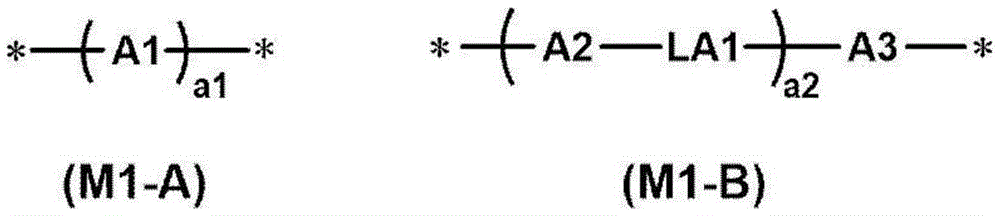
作为介晶基团,就液晶性的显现、液晶相转变温度的调整、原料获取性及合成适用性的观点、以及本发明的效果更优异的观点而言,优选为下述式(M1-A)或下述式(M1-B)所表示的基团,更优选为式(M1-B)所表示的基团。As the mesogenic group, the following formula (M1-A ) or a group represented by the following formula (M1-B), more preferably a group represented by formula (M1-B).
[化学式3][chemical formula 3]
式(M1-A)中,A1是选自包括芳香烃基、杂环基及脂环式基团的组中的2价基团。这些基团可以被烷基、氟化烷基、烷氧基或取代基取代。In the formula (M1-A), A1 is a divalent group selected from the group consisting of an aromatic hydrocarbon group, a heterocyclic group, and an alicyclic group. These groups may be substituted with alkyl, fluorinated alkyl, alkoxy or substituents.
A1所表示的2价基团优选为4~6元环。并且,A1所表示的2价基团可以是单环,也可以是稠环。The divalent group represented by A1 is preferably a 4- to 6-membered ring. In addition, the divalent group represented by A1 may be a monocyclic ring or a condensed ring.
*表示与SP1或T1的键合位置。*Indicates the bonding position to SP1 or T1.
作为A1所表示的2价的芳香烃基,可以举出亚苯基、亚萘基、芴-二基、蒽-二基及并四苯-二基等,从介晶骨架的设计多样性及原材料的获取性等观点考虑,优选为亚苯基或亚萘基,更优选为亚苯基。Examples of the divalent aromatic hydrocarbon group represented by A1 include phenylene, naphthylene, fluorene-diyl, anthracene-diyl, and naphthacene-diyl, etc. From the design diversity of the mesogenic skeleton and the raw materials From the viewpoint of availability, etc., phenylene or naphthylene is preferred, and phenylene is more preferred.
作为A1所表示的2价杂环基,可以是芳香族或非芳香族中的任一种,从取向度进一步得到提高的观点考虑,优选为2价芳香族杂环基。The divalent heterocyclic group represented by A1 may be either aromatic or non-aromatic, and is preferably a divalent aromatic heterocyclic group from the viewpoint of further improving the degree of orientation.
作为构成2价芳香族杂环基的除了碳以外的原子,可以举出氮原子、硫原子及氧原子。在芳香族杂环基具有多个除了碳以外的构成环的原子的情况下,这些原子可以相同,也可以不同。Examples of atoms other than carbon constituting the divalent aromatic heterocyclic group include a nitrogen atom, a sulfur atom, and an oxygen atom. When the aromatic heterocyclic group has a plurality of ring-forming atoms other than carbon, these atoms may be the same or different.
作为2价芳香族杂环基的具体例,例如,可以举出亚吡啶基(吡啶-二基)、哒嗪-二基、咪唑-二基、亚噻吩基(噻吩-二基)、亚喹啉基(喹啉-二基)、异亚喹啉基(异喹啉-二基)、噁唑-二基、噻唑-二基、噁二唑-二基、苯并噻唑-二基、苯并噻二唑-二基、邻苯二甲酰亚胺-二基、噻吩并噻唑-二基、噻唑并噻唑-二基、噻吩并噻吩-二基及噻吩并噁唑-二基等。Specific examples of the divalent aromatic heterocyclic group include, for example, pyridinylene (pyridine-diyl), pyridazine-diyl, imidazole-diyl, thienylene (thiophene-diyl), quinylene Linyl (quinoline-diyl), isoquinolinyl (isoquinoline-diyl), oxazole-diyl, thiazole-diyl, oxadiazole-diyl, benzothiazole-diyl, benzene Thiadiazole-diyl, phthalimide-diyl, thienothiazole-diyl, thiazolothiazole-diyl, thienothiophene-diyl, thienooxazole-diyl and the like.
作为A1所表示的2价的脂环式基团的具体例,可以举出亚环戊基及亚环己基等。Specific examples of the divalent alicyclic group represented by A1 include a cyclopentylene group, a cyclohexylene group, and the like.
上述式(M1-A)中,a1表示1~10的整数。在a1为2以上的情况下,多个A1可以相同也可以不同。In said formula (M1-A), a1 represents the integer of 1-10. When a1 is 2 or more, some A1 may be the same or different.
式(M1-B)中,A2及A3分别独立地为选自包括芳香烃基、杂环基及脂环式基团的组中的2价的基团。A2及A3的具体例及优选方式与式(M1-A)的A1相同,因此省略其说明。In the formula (M1-B), A2 and A3 are each independently a divalent group selected from the group consisting of an aromatic hydrocarbon group, a heterocyclic group, and an alicyclic group. Specific examples and preferred aspects of A2 and A3 are the same as those of A1 in the formula (M1-A), and therefore description thereof will be omitted.
式(M1-B)中,a2表示1~10的整数,在a2为2以上的情况下,多个A2可以相同也可以不同,多个A3可以相同也可以不同,多个LA1可以相同也可以不同。从所得到的光吸收各向异性层的取向度变得更高的理由考虑,a2优选为2以上的整数,更优选为2。In formula (M1-B), a2 represents an integer of 1 to 10. When a2 is 2 or more, multiple A2s may be the same or different, multiple A3s may be the same or different, and multiple LA1s may be the same or different. different. a2 is preferably an integer of 2 or more, more preferably 2, because the degree of orientation of the obtained light-absorbing anisotropic layer becomes higher.
式(M1-B)中,在a2为1的情况下,LA1为2价的连结基团。在a2为2以上的情况下,多个LA1分别独立地为单键或2价的连结基团,多个LA1中的至少一个为2价的连结基团。在a2为2的情况下,从所得到的光吸收各向异性层的取向度变得更高的理由考虑,优选2个LA1中,其中一个为2价的连结基团,另一个为单键。In formula (M1-B), when a2 is 1, LA1 is a divalent linking group. When a2 is 2 or more, several LA1 is each independently a single bond or a divalent linking group, and at least one of several LA1 is a divalent linking group. When a2 is 2, it is preferable that among the two LA1s, one is a divalent linking group and the other is a single bond, because the degree of orientation of the obtained light-absorbing anisotropic layer becomes higher. .
式(M1-B)中,作为LA1所表示的2价的连结基团,可以举出-O-、-(CH2)g-、-(CF2)g-、-Si(CH3)2-、-(Si(CH3)2O)g-、-(OSi(CH3)2)g-(g表示1~10的整数。)、-N(Z)-、-C(Z)=C(Z’)-、-C(Z)=N-、-N=C(Z)-、-C(Z)2-C(Z’)2-、-C(O)-、-OC(O)-、-C(O)O-、-O-C(O)O-、-N(Z)C(O)-、-C(O)N(Z)-、-C(Z)=C(Z’)-C(O)O-、-O-C(O)-C(Z)=C(Z’)-、-C(Z)=N-、-N=C(Z)-、-C(Z)=C(Z’)-C(O)N(Z”)-、-N(Z”)-C(O)-C(Z)=C(Z’)-、-C(Z)=C(Z’)-C(O)-S-、-S-C(O)-C(Z)=C(Z’)-、-C(Z)=N-N=C(Z’)-(Z、Z’、Z”独立地表示氢原子、C1~C4烷基、环烷基、芳基、氰基或卤原子。)、-C≡C-、-N=N-、-S-、-S(O)-、-S(O)(O)-、-(O)S(O)O-、-O(O)S(O)O-、-SC(O)-及-C(O)S-等。其中,从所得到的光吸收各向异性层的取向度变得更高的理由考虑,优选-C(O)O-。LA1也可以是将这些基团组合两个以上而成的基团。In the formula (M1-B), examples of the divalent linking group represented by LA1 include -O-, -(CH 2 ) g -, -(CF 2 ) g -, -Si(CH 3 ) 2 -, -(Si(CH 3 ) 2 O) g -, -(OSi(CH 3 ) 2 ) g -(g represents an integer of 1 to 10.), -N(Z)-, -C(Z)= C(Z')-, -C(Z)=N-, -N=C(Z)-, -C(Z) 2 -C(Z') 2 -, -C(O)-, -OC( O)-, -C(O)O-, -OC(O)O-, -N(Z)C(O)-, -C(O)N(Z)-, -C(Z)=C( Z')-C(O)O-, -OC(O)-C(Z)=C(Z')-, -C(Z)=N-, -N=C(Z)-, -C( Z)=C(Z')-C(O)N(Z")-, -N(Z")-C(O)-C(Z)=C(Z')-, -C(Z)= C(Z')-C(O)-S-, -SC(O)-C(Z)=C(Z')-, -C(Z)=NN=C(Z')-(Z, Z ', Z" independently represent hydrogen atom, C1~C4 alkyl group, cycloalkyl group, aryl group, cyano group or halogen atom.), -C≡C-, -N=N-, -S-, -S( O)-, -S(O)(O)-, -(O)S(O)O-, -O(O)S(O)O-, -SC(O)- and -C(O)S - etc. Among them, -C(O)O- is preferable because the degree of orientation of the obtained light-absorbing anisotropic layer becomes higher. LA1 may be formed by combining two or more of these groups group.
作为M1的具体例,例如可以举出以下结构。另外,在下述具体例中,“Ac”表示乙酰基。Specific examples of M1 include, for example, the following structures. In addition, in the following specific examples, "Ac" represents an acetyl group.
[化学式4][chemical formula 4]
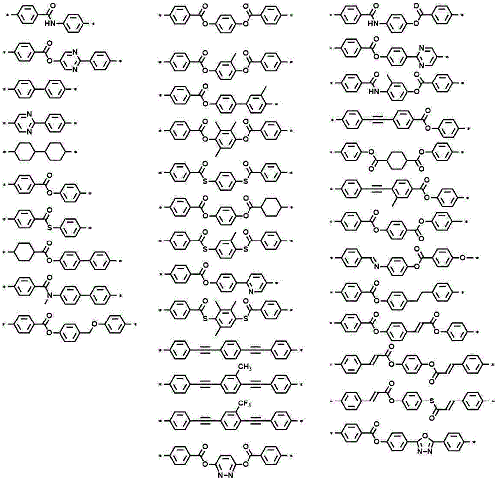
[化学式5][chemical formula 5]

作为T1所表示的末端基团,可以举出氢原子、卤原子、氰基、硝基、羟基、碳原子数1~10的烷基、碳原子数1~10的烷氧基、碳原子数1~10的烷硫基、碳原子数1~10的烷氧基羰基氧基、碳原子数1~10的烷氧基羰基(ROC(O)-:R为烷基)、碳原子数1~10的酰氧基、碳原子数1~10的酰氨基、碳原子数1~10的烷氧基羰基氨基、碳原子数1~10的磺酰基氨基、碳原子数1~10的氨磺酰基、碳原子数1~10的氨基甲酰基、碳原子数1~10的亚磺酰基、碳原子数1~10的脲基及含有(甲基)丙烯酰氧基的基团等。作为上述含有(甲基)丙烯酰氧基的基团,例如,可以举出-L-A(L表示单键或连结基团。连结基团的具体例与上述L1及SP1相同。A表示(甲基)丙烯酰氧基)所表示的基团。Examples of the terminal group represented by T1 include hydrogen atom, halogen atom, cyano group, nitro group, hydroxyl group, alkyl group having 1 to 10 carbon atoms, alkoxy group having 1 to 10 carbon atoms, alkoxy group having 1 to 10 carbon atoms, Alkylthio group with 1 to 10 carbon atoms, alkoxycarbonyloxy group with 1 to 10 carbon atoms, alkoxycarbonyl group with 1 to 10 carbon atoms (ROC(O)-: R is an alkyl group), 1 carbon atom Acyloxy group with 1 to 10 carbon atoms, amido group with 1 to 10 carbon atoms, alkoxycarbonylamino group with 1 to 10 carbon atoms, sulfonylamino group with 1 to 10 carbon atoms, sulfamosulfonic acid with 1 to 10 carbon atoms Acyl groups, carbamoyl groups having 1 to 10 carbon atoms, sulfinyl groups having 1 to 10 carbon atoms, ureido groups having 1 to 10 carbon atoms, groups containing (meth)acryloyloxy groups, and the like. As the above-mentioned group containing a (meth)acryloyloxy group, for example, -L-A (L represents a single bond or a linking group. Specific examples of the linking group are the same as the above-mentioned L1 and SP1. A represents (methyl ) a group represented by acryloyloxy).
从所得到的光吸收各向异性层的取向度变得更高的理由考虑,T1优选为碳原子数1~10的烷氧基,更优选为碳原子数1~5的烷氧基,进一步优选为甲氧基。这些末端基团可以被这些基团或日本特开2010-244038号公报中所记载的聚合性基团进一步取代。From the reason that the degree of orientation of the obtained light-absorbing anisotropic layer becomes higher, T1 is preferably an alkoxy group having 1 to 10 carbon atoms, more preferably an alkoxy group having 1 to 5 carbon atoms, and furthermore Methoxy is preferred. These terminal groups may be further substituted with these groups or the polymerizable groups described in JP-A-2010-244038.
从所得到的光吸收各向异性层的取向度变得更高的理由考虑,T1的主链的原子数优选为1~20,更优选为1~15,进一步优选为1~10,尤其优选为1~7。通过T1的主链的原子数为20以下,偏振器的取向度进一步得到提高。在此,T1中的“主链”是指与M1键合的最长的分子链,氢原子不计入T1的主链的原子数中。例如,在T1为正丁基的情况下,主链的原子数为4,在T1为仲丁基的情况下,主链的原子数为3。The number of atoms in the main chain of T1 is preferably 1 to 20, more preferably 1 to 15, still more preferably 1 to 10, and especially preferably 1 to 7. When the number of atoms in the main chain of T1 is 20 or less, the degree of orientation of the polarizer is further improved. Here, the "main chain" in T1 refers to the longest molecular chain bonded to M1, and hydrogen atoms are not included in the number of atoms in the main chain of T1. For example, when T1 is a n-butyl group, the number of atoms in the main chain is four, and when T1 is a sec-butyl group, the number of atoms in the main chain is three.
从所得到的光吸收各向异性层的取向度变得更高的理由考虑,相对于高分子液晶性化合物所具有的总重复单元100质量%,重复单元(1)的含量优选为20~100质量%。The content of the repeating unit (1) is preferably 20 to 100% by mass based on 100% by mass of the total repeating units contained in the polymer liquid crystalline compound because the degree of orientation of the obtained light-absorbing anisotropic layer becomes higher. quality%.
在本说明书中,基于为了得到各重复单元而使用的各单体的装入量(质量)来计算高分子液晶性化合物中所包含的各重复单元的含量。In this specification, the content of each repeating unit contained in a polymer liquid crystalline compound is calculated based on the loaded amount (mass) of each monomer used to obtain each repeating unit.
在高分子液晶性化合物中,可以单独包含1种重复单元(1),也可以包含2种以上。其中,从所得到的光吸收各向异性层的取向度变得更高的理由考虑,优选在高分子液晶性化合物中包含2种重复单元(1)。In the polymer liquid crystal compound, one type of repeating unit (1) may be contained alone, or two or more types may be contained. Among these, it is preferable to include two types of repeating units (1) in the polymer liquid crystal compound because the degree of orientation of the obtained light-absorbing anisotropic layer becomes higher.
在高分子液晶性化合物包含2种重复单元(1)的情况下,从所得到的光吸收各向异性层的取向度变得更高的理由考虑,在其中一个(重复单元A)中,T1所表示的末端基团为烷氧基,在另一个中(重复单元B)中,T1所表示的末端基团为除了烷氧基以外的基团。In the case where the polymer liquid crystalline compound contains two types of repeating units (1), in one of them (repeating unit A), T1 The terminal group represented is an alkoxy group, and in the other (repeating unit B), the terminal group represented by T1 is a group other than an alkoxy group.
从所得到的光吸收各向异性层的取向度变得更高的理由考虑,在上述重复单元B中,T1所表示的末端基团优选为烷氧基羰基、氰基或含有(甲基)丙烯酰氧基的基团,更优选为烷氧基羰基或氰基。In view of the reason that the degree of orientation of the obtained light-absorbing anisotropic layer becomes higher, in the above-mentioned repeating unit B, the terminal group represented by T1 is preferably an alkoxycarbonyl group, a cyano group, or a group containing (methyl) The acryloyloxy group is more preferably an alkoxycarbonyl group or a cyano group.
从所得到的光吸收各向异性层的取向度变得更高的理由考虑,高分子液晶性化合物中的上述重复单元A的含量与高分子液晶性化合物中的上述重复单元B的含量的比例(A/B)优选为50/50~95/5,更优选为60/40~93/7,进一步优选为70/30~90/10。The ratio of the content of the above-mentioned repeating unit A in the polymer liquid crystalline compound to the content of the above-mentioned repeating unit B in the polymer liquid crystalline compound is that the degree of orientation of the obtained light-absorbing anisotropic layer becomes higher (A/B) is preferably 50/50 to 95/5, more preferably 60/40 to 93/7, still more preferably 70/30 to 90/10.
(重复单元(3-2))(repeating unit (3-2))
高分子液晶性化合物还可以包含下述式(3-2)所表示的重复单元(在本说明书中,也称为“重复单元(3-2)”。)。由此,具有如下优点:高分子液晶性化合物在溶剂中的溶解性得到提高及液晶相转变温度的调整等变得容易。The polymer liquid crystalline compound may further contain a repeating unit represented by the following formula (3-2) (in this specification, it is also referred to as "repeating unit (3-2)"). Thereby, there are advantages in that the solubility of the polymer liquid crystal compound in the solvent is improved, and the adjustment of the phase transition temperature of the liquid crystal is facilitated.
重复单元(3-2)与上述重复单元(1)的不同点在于,至少不具有介晶基团。The repeating unit (3-2) differs from the repeating unit (1) above in that it does not have at least a mesogenic group.
在高分子液晶性化合物包含重复单元(3-2)的情况下,高分子液晶性化合物可以为重复单元(1)与重复单元(3-2)的共聚物,进而可以为包含重复单元A、B的共聚物。上述共聚物可以为封端聚合物、交替聚合物、无规聚合物及接枝聚合物等任何聚合物。In the case where the polymer liquid crystalline compound contains the repeating unit (3-2), the polymer liquid crystalline compound may be a copolymer of the repeating unit (1) and the repeating unit (3-2), and further may be a copolymer comprising the repeating unit A, Copolymer of B. The above-mentioned copolymers may be any polymers such as end-capped polymers, alternating polymers, random polymers and graft polymers.
[化学式6][chemical formula 6]

式(3-2)中,P3表示重复单元的主链,L3表示单键或2价的连结基团,SP3表示间隔基团,T3表示末端基团。In formula (3-2), P3 represents the main chain of the repeating unit, L3 represents a single bond or a divalent linking group, SP3 represents a spacer group, and T3 represents a terminal group.
式(3-2)中的P3、L3、SP3及T3的具体例分别与上述式(1)中的P1、L1、SP1及T1相同。Specific examples of P3, L3, SP3, and T3 in formula (3-2) are the same as those of P1, L1, SP1, and T1 in formula (1) above, respectively.
在此,从光吸收各向异性层的强度提高的观点考虑,式(3-2)中的T3优选具有聚合性基团。Here, from the viewpoint of improving the strength of the light-absorbing anisotropic layer, T3 in the formula (3-2) preferably has a polymerizable group.
包含重复单元(3-2)时的含量相对于高分子液晶性化合物所具有的总重复单元100质量%,优选为0.5~40质量%,更优选为1~30质量%。When the repeating unit (3-2) is included, the content is preferably 0.5 to 40 mass%, more preferably 1 to 30 mass%, based on 100 mass% of the total repeating units contained in the polymer liquid crystal compound.
在高分子液晶性化合物中,可以单独包含1种重复单元(3-2),也可以包含2种以上。在包含2种以上重复单元(3-2)的情况下,其合计量优选在上述范围内。In the polymer liquid crystal compound, one type of repeating unit (3-2) may be contained alone, or two or more types may be contained. When two or more repeating units (3-2) are included, the total amount thereof is preferably within the above range.
(重均分子量)(weight average molecular weight)
从所得到的光吸收各向异性层的取向度变得更高的理由考虑,高分子液晶性化合物的重均分子量(Mw)优选为1000~500000,更优选为2000~300000。若高分子液晶性化合物的Mw在上述范围内,则高分子液晶性化合物的处理变得容易。The weight-average molecular weight (Mw) of the polymer liquid crystalline compound is preferably 1,000 to 500,000, more preferably 2,000 to 300,000, because the obtained light-absorbing anisotropic layer has a higher degree of orientation. When the Mw of the polymer liquid crystal compound is within the above range, the polymer liquid crystal compound can be easily handled.
尤其,从抑制涂布时的裂纹的观点考虑,高分子液晶性化合物的重均分子量(Mw)优选为10000以上,更优选为10000~300000。In particular, the weight average molecular weight (Mw) of the polymer liquid crystal compound is preferably 10,000 or more, more preferably 10,000 to 300,000, from the viewpoint of suppressing cracks during coating.
并且,从取向度的温度宽容度的观点考虑,高分子液晶性化合物的重均分子量(Mw)优选为小于10000,优选为2000以上且小于10000。Furthermore, from the viewpoint of the temperature latitude of the degree of orientation, the weight average molecular weight (Mw) of the polymer liquid crystal compound is preferably less than 10,000, preferably 2,000 or more and less than 10,000.
在此,本说明书中所记载的重均分子量及数均分子量是通过凝胶渗透色谱(GPC)法测定出的值。Here, the weight average molecular weight and number average molecular weight described in this specification are the values measured by the gel permeation chromatography (GPC) method.
·溶剂(洗脱液):N-甲基吡咯烷酮Solvent (eluent): N-methylpyrrolidone
·装置名称:TOSOH HLC-8220GPC·Device name: TOSOH HLC-8220GPC
·管柱:将3根TOSOH TSKgelSuperAWM-H(6mm×15cm)连接使用·Column: connect 3 pieces of TOSOH TSKgelSuperAWM-H (6mm×15cm)
·管柱温度:25℃·Column temperature: 25℃
·试样浓度:0.1质量%・Sample concentration: 0.1% by mass
·流速:0.35mL/min·Flow rate: 0.35mL/min
·校准曲线:使用由TOSOH CORPORATION制TSK标准聚苯乙烯Mw=2800000~1050(Mw/Mn=1.03~1.06)的7个样品得到的校准曲线・Calibration curve: Calibration curve obtained using 7 samples of TSK standard polystyrene Mw = 2,800,000 to 1,050 (Mw/Mn = 1.03 to 1.06) manufactured by TOSOH CORPORATION
(含量)(content)
液晶性化合物的含量优选为成为光吸收各向异性层形成用组合物中的固体成分中的50~99质量%的量,更优选为成为70~96质量%的量。The content of the liquid crystal compound is preferably an amount of 50 to 99% by mass in the solid content of the composition for forming an anisotropic light absorption layer, more preferably an amount of 70 to 96% by mass.
在此,“光吸收各向异性层形成用组合物中的固体成分”是指,除了溶剂以外的成分。作为固体成分的具体例,可以举出上述液晶性化合物及后述的二色性物质、聚合引发剂及表面活性剂。Here, the "solid content in the light-absorbing anisotropic layer-forming composition" refers to components other than the solvent. Specific examples of the solid content include the aforementioned liquid crystalline compounds, dichroic substances, polymerization initiators, and surfactants described later.
<二色性物质><Dichroic substances>
光吸收各向异性层形成用组合物包含二色性物质。The composition for forming an anisotropic light-absorbing layer contains a dichroic substance.
作为二色性物质,并没有特别限制,能够使用公知的二色性物质(二色性色素),例如,可以举出可见光吸收物质(二色性色素)、发光物质(荧光物质、磷光物质)、紫外线吸收物质、红外线吸收物质、非线形光学物质、碳纳米管及无机物质(例如量子杆)。The dichroic substance is not particularly limited, and known dichroic substances (dichroic dyes) can be used, for example, visible light absorbing substances (dichroic dyes), luminescent substances (fluorescent substances, phosphorescent substances) , UV-absorbing substances, infrared-absorbing substances, nonlinear optical substances, carbon nanotubes and inorganic substances (such as quantum rods).
作为二色性物质,例如可以举出日本特开2013-228706号公报的[0067]至[0071]段、日本特开2013-227532号公报的[0008]至[0026]段、日本特开2013-209367号公报的[0008]至[0015]段、日本特开2013-14883号公报的[0045]至[0058]段、日本特开2013-109090号公报的[0012]至[0029]段、日本特开2013-101328号公报的[0009]至[0017]段、日本特开2013-37353号公报的[0051]至[0065]段、日本特开2012-063387号公报的[0049]至[0073]段、日本特开平11-305036号公报的[0016]至[0018]段、日本特开2001-133630号公报的[0009]至[0011]段、日本特开2011-215337号公报的[0030]至[0169]段、日本特开2010-106242号公报的[0021]至[0075]段、日本特开2010-215846号公报的[0011]至[0025]段、日本特开2011-048311号公报的[0017]至[0069]段、日本特开2011-213610号公报的[0013]至[0133]段、日本特开2011-237513号公报的[0074]至[0246]段、日本特开2016-006502号公报的[0005]至[0051]段、国际公开第2016/060173号的[0005]至[0041]段、国际公开第2016/136561号的[0008]至[0062]段、国际公开第2017/154835号的[0014]至[0033]段、国际公开第2017/154695号的[0014]至[0033]段、国际公开第2017/195833号的[0013]至[0037]段、国际公开第2018/164252号的[0014]至[0034]段中所记载的二色性物质。Examples of dichroic substances include paragraphs [0067] to [0071] of JP 2013-228706 A, paragraphs [0008] to [0026] of JP 2013-227532 A, JP 2013 - Paragraphs [0008] to [0015] of Japanese Patent Application Publication No. 209367, paragraphs [0045] to [0058] of Japanese Patent Application Publication No. 2013-14883, paragraphs [0012] to [0029] of Japanese Patent Application Publication No. 2013-109090, Paragraphs [0009] to [0017] of Japanese Patent Application Laid-Open No. 2013-101328, paragraphs [0051] to [0065] of Japanese Patent Application Laid-Open No. 2013-37353, paragraphs [0049] to [0065] of Japanese Patent Application Laid-Open No. 2012-063387 paragraph [0073], [0016] to [0018] of Japanese Patent Application Publication No. 11-305036, [0009] to [0011] of Japanese Patent Application Publication No. 2001-133630, [ Paragraphs [0030] to [0169], paragraphs [0021] to [0075] of JP 2010-106242, paragraphs [0011] to [0025] of JP 2010-215846, JP 2011-048311 No. [0017] to [0069] of the Publication, [0013] to [0133] of the Japanese Patent Application Publication No. 2011-213610, [0074] to [0246] of the Japanese Patent Application Publication No. Paragraphs [0005] to [0051] of Publication No. 2016-006502, paragraphs [0005] to [0041] of International Publication No. 2016/060173, paragraphs [0008] to [0062] of International Publication No. 2016/136561, Paragraphs [0014] to [0033] of International Publication No. 2017/154835, paragraphs [0014] to [0033] of International Publication No. 2017/154695, and paragraphs [0013] to [0037] of International Publication No. 2017/195833 , the dichroic substance described in paragraphs [0014] to [0034] of International Publication No. 2018/164252.
光吸收各向异性层可以包含2种以上的二色性物质,例如,从使所得到的液晶层接近于黑色的观点考虑,优选并用在波长370~550nm的范围内具有极大吸收波长的至少1种二色性物质和在波长500~700nm的范围内具有极大吸收波长的至少1种二色性物质。The light-absorbing anisotropic layer may contain two or more dichroic substances. For example, from the viewpoint of making the obtained liquid crystal layer close to black, it is preferable to use together at least one having a maximum absorption wavelength in the wavelength range of 370 to 550 nm. One dichroic substance and at least one dichroic substance having a maximum absorption wavelength within a wavelength range of 500 to 700 nm.
光吸收各向异性层形成用组合物中所包含的二色性物质可以具有交联性基团。尤其,就抑制加热时的偏振度变化的观点而言,二色性物质优选具有交联性基团。The dichroic substance contained in the composition for light absorption anisotropic layer formation may have a crosslinkable group. In particular, the dichroic substance preferably has a crosslinkable group from the viewpoint of suppressing a change in the degree of polarization during heating.
作为上述交联性基团,例如,可以举出(甲基)丙烯酰基、环氧基、氧杂环丁基及苯乙烯基,其中,优选(甲基)丙烯酰基。As said crosslinkable group, a (meth)acryloyl group, an epoxy group, an oxetanyl group, and a styryl group are mentioned, for example, Among these, a (meth)acryloyl group is preferable.
(含量)(content)
从二色性物质的取向度变得更高的理由考虑,光吸收各向异性层形成用组合物的二色性物质的含量相对于上述液晶性化合物100质量份优选为1~400质量份,更优选为2~100质量份,进一步优选为5~30质量份。The content of the dichroic substance in the composition for forming an anisotropic light-absorbing layer is preferably 1 to 400 parts by mass relative to 100 parts by mass of the liquid crystal compound, because the degree of orientation of the dichroic substance becomes higher, More preferably, it is 2-100 mass parts, More preferably, it is 5-30 mass parts.
<表面活性剂><Surfactant>
光吸收各向异性层形成用组合物可以包含表面活性剂。The composition for forming a light-absorbing anisotropic layer may contain a surfactant.
作为光吸收各向异性层形成用组合物中所包含的表面活性剂,能够使用公知的表面活性剂,但优选为具有包含氟化烷基的重复单元(以下,也简称为“重复单元F”。)和包含环结构的重复单元(以下,也简称为“重复单元M”。)的共聚物。Known surfactants can be used as the surfactant contained in the composition for forming an anisotropic light-absorbing layer, but those having a repeating unit containing a fluorinated alkyl group (hereinafter also simply referred to as "repeating unit F") .) and a repeating unit comprising a ring structure (hereinafter also simply referred to as "repeating unit M".) Copolymer.
(重复单元F)(repeating unit F)
上述共聚物所具有的重复单元F优选为下述式(a)所表示的重复单元。The repeating unit F contained in the above-mentioned copolymer is preferably a repeating unit represented by the following formula (a).
[化学式7][chemical formula 7]

上述式(a)中,Ra1表示氢原子或碳原子数1~20的烷基,Ra2表示至少1个碳原子具有氟原子作为取代基的碳原子数1~20的烷基或碳原子数2~20的烯基。In the above formula (a), R a1 represents a hydrogen atom or an alkyl group having 1 to 20 carbon atoms, and R a2 represents an alkyl group having 1 to 20 carbon atoms or a carbon atom having at least one carbon atom having a fluorine atom as a substituent Alkenyl with the number 2-20.
上述式(a)中,从所得到的光吸收各向异性层的取向缺陷进一步得到抑制的理由考虑,Ra2优选为至少1个碳原子具有氟原子作为取代基的碳原子数1~10的烷基或碳原子数2~10的亚烯基,更优选为碳原子数1~10的烷基,尤其优选Ra2中所包含的半数以上的碳原子具有氟原子作为取代基。In the above formula (a), R a2 is preferably a carbon atom having 1 to 10 carbon atoms having a fluorine atom as a substituent in order to further suppress the alignment defects of the obtained light-absorbing anisotropic layer. An alkyl group or an alkenylene group having 2 to 10 carbon atoms is more preferably an alkyl group having 1 to 10 carbon atoms, and it is especially preferable that half or more of the carbon atoms included in R a2 have fluorine atoms as substituents.
上述共聚物所具有的重复单元F更优选为下述式(b)所表示的重复单元。The repeating unit F contained in the copolymer is more preferably a repeating unit represented by the following formula (b).
[化学式8][chemical formula 8]
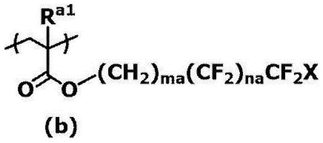
上述式(b)中,Ra1表示氢原子或碳原子数1~20的烷基,ma及na分别独立地表示0以上的整数,X表示氢原子或氟原子。In the above formula (b), R a1 represents a hydrogen atom or an alkyl group having 1 to 20 carbon atoms, ma and na each independently represent an integer of 0 or more, and X represents a hydrogen atom or a fluorine atom.
在此,ma优选为1以上且10以下的整数,na优选为4以上且12以下。Here, ma is preferably an integer of 1 to 10, and na is preferably 4 to 12.
作为形成上述共聚物所具有的重复单元F的单体(以下,也简称为“含有氟烷基的单体”。),例如,可以举出2,2,2-(甲基)丙烯酸三氟乙酯、2,2,3,3,3-五氟(甲基)丙烯酸丙酯、2-(全氟丁基)(甲基)丙烯酸乙酯、2-(全氟己基)(甲基)丙烯酸乙酯、2-(全氟辛基)(甲基)丙烯酸乙酯、2-(全氟癸基)(甲基)丙烯酸乙酯、2-(全氟-3-甲基丁酯)(甲基)丙烯酸乙酯、2-(全氟-5-甲基己基)(甲基)丙烯酸乙酯、2-(全氟-7-甲基辛基)(甲基)丙烯酸乙酯、1H,1H,3H-四氟丙基(甲基)丙烯酸酯、1H,1H,5H-八氟(甲基)丙烯酸戊酯、1H,1H,7H-十二氟庚基(甲基)丙烯酸酯、1H,1H,9H-十六氟壬基(甲基)丙烯酸酯、1H-1-(三氟甲基)(甲基)丙烯酸三氟乙酯、1H,1H,3H-六氟(甲基)丙烯酸丁酯、3-全氟丁基-(甲基)丙烯酸2-羟基丙酯、3-全氟己基-(甲基)丙烯酸2-羟基丙酯、3-全氟辛基-(甲基)丙烯酸2-羟基丙酯、3-(全氟-3-甲基丁酯)-(甲基)丙烯酸2-羟基丙酯、3-(全氟-5-甲基己基)-(甲基)丙烯酸2-羟基丙酯及3-(全氟-7-甲基辛基)-(甲基)丙烯酸2-羟基丙酯。As a monomer forming the repeating unit F of the above-mentioned copolymer (hereinafter also simply referred to as "fluoroalkyl-containing monomer"), for example, 2,2,2-(meth)acrylic acid trifluoro Ethyl ester, 2,2,3,3,3-pentafluoropropyl (meth)acrylate, 2-(perfluorobutyl)ethyl (meth)acrylate, 2-(perfluorohexyl)(methyl) Ethyl acrylate, 2-(perfluorooctyl)(meth)ethylacrylate, 2-(perfluorodecyl)(meth)ethylacrylate, 2-(perfluoro-3-methylbutyl)( Ethyl meth)acrylate, ethyl 2-(perfluoro-5-methylhexyl)(meth)acrylate, ethyl 2-(perfluoro-7-methyloctyl)(meth)acrylate, 1H, 1H,3H-tetrafluoropropyl(meth)acrylate, 1H,1H,5H-pentyl octafluoro(meth)acrylate, 1H,1H,7H-dodecafluoroheptyl(meth)acrylate, 1H ,1H,9H-hexadecafluorononyl(meth)acrylate, 1H-1-(trifluoromethyl)(meth)acrylate trifluoroethyl, 1H,1H,3H-hexafluoro(meth)acrylate Butyl ester, 3-perfluorobutyl-2-hydroxypropyl (meth)acrylate, 3-perfluorohexyl-2-hydroxypropyl (meth)acrylate, 3-perfluorooctyl-(meth)acrylic acid 2-hydroxypropyl ester, 3-(perfluoro-3-methylbutyl)-(meth)acrylate 2-hydroxypropyl ester, 3-(perfluoro-5-methylhexyl)-(meth)acrylic acid 2 -Hydroxypropyl ester and 2-hydroxypropyl 3-(perfluoro-7-methyloctyl)-(meth)acrylate.
关于使含有氟烷基的单体共聚合的比例,从反应性及表面改性效果的观点考虑,相对于具有后述的介晶基团的单体1摩尔,优选为0.01~100摩尔,更优选为0.1~50摩尔,更优选为1~30摩尔。The ratio of copolymerizing the fluoroalkyl-containing monomer is preferably 0.01 to 100 moles, more preferably 0.01 to 100 moles, relative to 1 mole of a monomer having a mesogenic group described later, from the viewpoint of reactivity and surface modification effect. Preferably it is 0.1-50 mol, More preferably, it is 1-30 mol.
(重复单元M)(repeating unit M)
上述共聚物所具有的重复单元M只要是包含环结构的单元即可。The repeating unit M which the said copolymer has should just be a unit containing a ring structure.
作为环结构,例如,可以举出选自包括芳香烃基、杂环基及脂环式基团的组中的至少1种环结构。从抑制取向缺陷的观点考虑,重复单元M优选具有2个以上的环结构。Examples of the ring structure include at least one ring structure selected from the group consisting of an aromatic hydrocarbon group, a heterocyclic group, and an alicyclic group. From the viewpoint of suppressing alignment defects, the repeating unit M preferably has two or more ring structures.
上述共聚物所具有的重复单元M更优选为下述式(b)所表示的重复单元。As for the repeating unit M which the said copolymer has, it is more preferable that it is a repeating unit represented by following formula (b).
[化学式9][chemical formula 9]

上述式(c)中,Ra1表示氢原子或碳原子数1~20的烷基,L4及L5分别独立地表示单键或碳原子数1~8的亚烷基,G1及G2分别独立地表示2价的环状基团,T4表示末端基团。n表示0~4的整数。在n表示2~4的整数的情况下,2个以上的L5可以相同也可以不同,2个以上的G2可以相同也可以不同。In the above formula (c), R a1 represents a hydrogen atom or an alkyl group having 1 to 20 carbon atoms, L4 and L5 independently represent a single bond or an alkylene group having 1 to 8 carbon atoms, and G1 and G2 independently represent represents a divalent cyclic group, and T4 represents a terminal group. n represents an integer of 0-4. When n represents an integer of 2 to 4, two or more L5 may be the same or different, and two or more G2 may be the same or different.
关于L4及L5所表示的亚烷基,构成亚烷基的1个以上的-CH2-可以被选自包括单键、-O-、-S-、-NR31-、-C(=O)-、-C(=S)-、-CR32=CR32-、-C≡C-、-SiR33R34-、-N=N-、-CR35=N-N=CR36-、-CR37=N-及-SO2-的组中的至少1种基团取代,R31~R37分别独立地表示氢原子、卤原子、氰基、硝基或碳原子数1~10的直链状或支链状的烷基。Regarding the alkylene group represented by L4 and L5, one or more -CH 2 - constituting the alkylene group can be selected from single bond, -O-, -S-, -NR 31 -, -C(=O )-, -C(=S)-, -CR 32 =CR 32 -, -C≡C-, -SiR 33 R 34 -, -N=N-, -CR 35 =NN=CR 36 -, -CR 37 = Substitution by at least one of the groups of N- and -SO 2 -, R 31 to R 37 each independently represent a hydrogen atom, a halogen atom, a cyano group, a nitro group, or a straight chain having 1 to 10 carbon atoms Alkyl or branched chain.
并且,在L4或L5表示亚烷基的情况下,构成亚烷基的1个以上的-CH2-中所包含的氢原子可以被选自包括卤原子、氰基、硝基、羟基、碳原子数1~10的直链状的烷基及碳原子数1~10的支链状的烷基的组中的至少1种基团取代。In addition, when L4 or L5 represents an alkylene group, the hydrogen atoms contained in one or more -CH2- constituting the alkylene group can be selected from halogen atoms, cyano groups, nitro groups, hydroxyl groups, carbon It is substituted by at least one group of a linear alkyl group having 1 to 10 atoms and a branched alkyl group having 1 to 10 carbon atoms.
其中,L4优选为碳原子数4~6且末端为氧的亚烷基氧基,L5优选为酯基。Among them, L4 is preferably an alkyleneoxy group having 4 to 6 carbon atoms and having an oxygen terminal, and L5 is preferably an ester group.
G1及G2所表示的2价的环状基团分别独立地表示碳原子数5~8的2价的脂环式烃基或芳香烃基,构成上述脂环式烃基的1个以上的-CH2-可以被-O-、-S-或-NH-取代。而且,上述2价的环状基团可以是由选自脂环式烃基及芳香族烃基的多个基团单键而形成的2价的基团。其中,优选为苯环。The divalent cyclic groups represented by G1 and G2 each independently represent a divalent alicyclic hydrocarbon group or aromatic hydrocarbon group having 5 to 8 carbon atoms, and one or more -CH 2 - constituting the above alicyclic hydrocarbon group Can be substituted by -O-, -S- or -NH-. Furthermore, the divalent cyclic group may be a divalent group formed of single bonds of a plurality of groups selected from alicyclic hydrocarbon groups and aromatic hydrocarbon groups. Among them, a benzene ring is preferable.
作为T4所表示的末端基团,可以举出氢原子、卤原子、氰基、硝基、羟基、碳原子数1~10的烷基、碳原子数1~10的烷氧基、碳原子数1~10的烷硫基、碳原子数1~10的烷氧基羰基氧基、碳原子数1~10的烷氧基羰基(ROC(O)-:R为碳原子数1~10的烷基)、碳原子数1~10的酰氧基、碳原子数1~10的酰氨基、碳原子数1~10的烷氧基羰基氨基、碳原子数1~10的磺酰基氨基、碳原子数1~10的氨磺酰基、碳原子数1~10的氨基甲酰基、碳原子数1~10的亚磺酰基、碳原子数1~10的脲基及含有(甲基)丙烯酰氧基的基团。其中,优选为氢原子或氰基。Examples of the terminal group represented by T4 include hydrogen atom, halogen atom, cyano group, nitro group, hydroxyl group, alkyl group having 1 to 10 carbon atoms, alkoxy group having 1 to 10 carbon atoms, alkoxy group having 1 to 10 carbon atoms, Alkylthio group with 1 to 10 carbon atoms, alkoxycarbonyloxy group with 1 to 10 carbon atoms, alkoxycarbonyl group with 1 to 10 carbon atoms (ROC(O)-: R is an alkane with 1 to 10 carbon atoms group), acyloxy group with 1 to 10 carbon atoms, amido group with 1 to 10 carbon atoms, alkoxycarbonylamino group with 1 to 10 carbon atoms, sulfonylamino group with 1 to 10 carbon atoms, carbon atom A sulfamoyl group with 1 to 10 carbon atoms, a carbamoyl group with 1 to 10 carbon atoms, a sulfinyl group with 1 to 10 carbon atoms, a ureido group with 1 to 10 carbon atoms, and a (meth)acryloyloxy group group. Among them, a hydrogen atom or a cyano group is preferable.
关于重复单元F相对于上述共聚物所具有的所有重复单元的摩尔比,从取向度的观点而言,优选为50摩尔%以上,从凹陷的观点考虑,优选为70摩尔%以下。The molar ratio of the repeating unit F to all the repeating units of the copolymer is preferably 50 mol% or more from the viewpoint of orientation, and preferably 70 mol% or less from the viewpoint of craters.
(含量)(content)
从所得到的光吸收各向异性层的取向度变得更高的理由考虑,上述的表面活性剂的含量相对于上述液晶性化合物100质量份优选为0.05~15质量份,更优选为0.08~10质量份,进一步优选为0.1~5质量份。The content of the surfactant is preferably from 0.05 to 15 parts by mass, more preferably from 0.08 to 100 parts by mass, based on 100 parts by mass of the above-mentioned liquid crystal compound, because the degree of orientation of the obtained light-absorbing anisotropic layer becomes higher. 10 parts by mass, more preferably 0.1 to 5 parts by mass.
<聚合引发剂><Polymerization Initiator>
光吸收各向异性层形成用组合物优选包含聚合引发剂。The composition for forming a light-absorbing anisotropic layer preferably contains a polymerization initiator.
作为聚合引发剂,并没有特别的限制,但优选具有感光性的化合物、即光聚合引发剂。The polymerization initiator is not particularly limited, but is preferably a photosensitive compound, that is, a photopolymerization initiator.
作为光聚合引发剂,能够无特别限制地使用各种化合物。作为具体的光聚合引发剂,可以举出α-羰基化合物(美国专利第2367661号及美国专利第2367670号的各说明书)、偶姻醚(美国专利第2448828号说明书)、α-烃取代芳香族偶姻化合物(美国专利第2722512号说明书)、多核醌化合物(美国专利第3046127号及美国专利第2951758号的各说明书)、三芳基咪唑二聚体和对氨基苯基酮的组合(美国专利第3549367号说明书)、吖啶及吩嗪化合物(日本特开昭60-105667号公报及美国专利第4239850号说明书)、恶二唑化合物(美国专利第4212970号说明书)、邻酰基肟化合物(日本特开2016-027384公报[0065]段)、以及酰基氧化膦化合物(日本特公昭63-040799号公报、日本特公平5-029234号公报、日本特开平10-095788号公报及日本特开平10-029997号公报)。As the photopolymerization initiator, various compounds can be used without particular limitation. Specific photopolymerization initiators include α-carbonyl compounds (specifications of U.S. Patent No. 2,367,661 and U.S. Patent No. 2,367,670), azoinyl ethers (specifications of U.S. Patent No. 2,448,828), α-hydrocarbon-substituted aromatic Combinations of azoin compounds (US Patent No. 2722512 specifications), polynuclear quinone compounds (US Patent No. 3046127 and US Patent No. 2951758 specifications), triaryl imidazole dimers and p-aminophenyl ketones (US Patent No. 3549367 specifications), acridine and phenazine compounds (Japanese Patent Application Publication No. 60-105667 and US Patent No. 4239850 specifications), oxadiazole compounds (US Patent No. 2016-027384 communiqué [0065]), and acylphosphine oxide compounds (Japanese Patent Publication No. 63-040799, Japanese Patent Publication No. 5-029234, Japanese Patent Publication No. 10-095788 and Japanese Patent Publication No. 10-029997 Bulletin).
作为这种光聚合引发剂,也能够使用市售品。作为光聚合引发剂的市售品,例如,可以举出BASF公司制的Irgacure184、Irgacure907、Irgacure369、Irgacure651、Irgacure819、Irgacure OXE-01及Irgacure OXE-02。As such a photoinitiator, a commercial item can also be used. As a commercial item of a photoinitiator, Irgacure 184, Irgacure 907, Irgacure 369, Irgacure 651, Irgacure 819, Irgacure OXE-01, and Irgacure OXE-02 by BASF Corporation are mentioned, for example.
在光吸收各向异性层形成用组合物包含聚合引发剂的情况下,相对于光吸收各向异性层形成用组合物中的上述二色性物质和上述高分子液晶性化合物的合计100质量份,聚合引发剂的含量优选为0.01~30质量份,更优选为0.1~15质量份。通过聚合引发剂的含量为0.01质量份以上,光吸收各向异性膜的耐久性变得良好,通过为30质量份以下,光吸收各向异性膜的取向度变得更良好。When the composition for forming an anisotropic light-absorbing layer contains a polymerization initiator, with respect to 100 parts by mass of the total of the above-mentioned dichroic substance and the above-mentioned polymer liquid crystal compound in the composition for forming an anisotropic light-absorbing layer , The content of the polymerization initiator is preferably 0.01 to 30 parts by mass, more preferably 0.1 to 15 parts by mass. When the content of the polymerization initiator is at least 0.01 parts by mass, the durability of the anisotropic light-absorbing film becomes favorable, and when the content of the polymerization initiator is at most 30 parts by mass, the degree of orientation of the anisotropic light-absorbing film becomes more favorable.
聚合引发剂可以单独使用1种,也可以同时使用2种以上。在包含2种以上的聚合引发剂的情况下,优选其合计量在上述范围内。A polymerization initiator may be used individually by 1 type, and may use 2 or more types together. When including two or more types of polymerization initiators, the total amount thereof is preferably within the above range.
<溶剂><Solvent>
从操作性的观点考虑,光吸收各向异性层形成用组合物优选包含溶剂。It is preferable that the composition for light absorption anisotropic layer formation contains a solvent from a viewpoint of handleability.
作为溶剂,例如可以举出酮类(例如,丙酮、2-丁酮、甲基异丁基酮、环戊酮、环己酮等)、醚类(例如,二噁烷、四氢呋喃、2-甲基四氢呋喃、环戊基甲醚、四氢吡喃、二氧戊环等)、脂肪族烃类(例如,己烷等)、脂环式烃类(例如,环己烷等)、芳香族烃类(例如,苯、甲苯、二甲苯、三甲基苯等)、卤代碳类(例如,二氯甲烷、三氯甲烷、二氯乙烷、二氯苯、氯甲苯等)、酯类(例如,乙酸甲酯、乙酸乙酯、乙酸丁酯、乳酸乙酯等)、醇类(例如,乙醇、异丙醇、丁醇、环己醇、异戊醇、新戊醇、二丙酮醇、苄醇等)、溶纤剂类(例如,甲基溶纤剂、乙基溶纤剂、1,2-二甲氧基乙烷等)、溶纤剂乙酸酯类、亚砜类(例如,二甲基亚砜等)、酰胺类(例如,二甲基甲酰胺、二甲基乙酰胺、N-甲基吡咯烷酮、N-乙基吡咯烷酮等)及杂环化合物(例如,吡啶等)等有机溶剂以及水。Examples of solvents include ketones (for example, acetone, 2-butanone, methyl isobutyl ketone, cyclopentanone, cyclohexanone, etc.), ethers (for example, dioxane, tetrahydrofuran, 2-methyl tetrahydrofuran, cyclopentyl methyl ether, tetrahydropyran, dioxolane, etc.), aliphatic hydrocarbons (such as hexane, etc.), alicyclic hydrocarbons (such as cyclohexane, etc.), aromatic hydrocarbons (for example, benzene, toluene, xylene, trimethylbenzene, etc.), halogenated carbons (for example, dichloromethane, chloroform, dichloroethane, dichlorobenzene, chlorotoluene, etc.), esters ( For example, methyl acetate, ethyl acetate, butyl acetate, ethyl lactate, etc.), alcohols (for example, ethanol, isopropanol, butanol, cyclohexanol, isoamyl alcohol, neopentyl alcohol, diacetone alcohol, benzyl alcohol, etc.), cellosolves (for example, methyl cellosolve, ethyl cellosolve, 1,2-dimethoxyethane, etc.), cellosolve acetates, sulfoxides (for example, Dimethylsulfoxide, etc.), amides (e.g., dimethylformamide, dimethylacetamide, N-methylpyrrolidone, N-ethylpyrrolidone, etc.) and heterocyclic compounds (e.g., pyridine, etc.) solvents and water.
溶剂可以单独使用1种,也可以同时使用2种以上。A solvent may be used individually by 1 type, and may use 2 or more types together.
在这些溶剂中,从利用溶解性优异的效果的观点考虑,优选酮类(特别是环戊酮或环己酮)、醚类(特别是四氢呋喃、环戊基甲醚、四氢吡喃或二氧戊环)或酰胺类(特别是二甲基甲酰胺、二甲基乙酰胺、N-甲基吡咯烷酮或N-乙基吡咯烷酮)。Among these solvents, ketones (especially cyclopentanone or cyclohexanone), ethers (especially tetrahydrofuran, cyclopentyl methyl ether, tetrahydropyran, or Oxolane) or amides (especially dimethylformamide, dimethylacetamide, N-methylpyrrolidone or N-ethylpyrrolidone).
在光吸收各向异性层形成用组合物包含溶剂的情况下,溶剂的含量相对于光吸收各向异性层形成用组合物的总质量,优选为80~99质量%,更优选为83~97质量%,尤其优选为85~95质量%。When the composition for forming an anisotropic light-absorbing layer contains a solvent, the content of the solvent is preferably 80 to 99% by mass, more preferably 83 to 97% by mass, based on the total mass of the composition for forming an anisotropic light-absorbing layer. % by mass, particularly preferably 85 to 95% by mass.
溶剂可以单独使用1种,也可以并用2种以上。在包含2种以上的溶剂的情况下,优选其合计量在上述范围内。A solvent may be used individually by 1 type, and may use 2 or more types together. When two or more solvents are included, the total amount is preferably within the above range.
关于光吸收各向异性层的厚度,并没有特别限制,从使光学元件薄型化的观点考虑,优选为100~8000nm,更优选为300~5000nm。The thickness of the light-absorbing anisotropic layer is not particularly limited, but is preferably 100 to 8000 nm, more preferably 300 to 5000 nm, from the viewpoint of reducing the thickness of the optical element.
<<取向膜>><<Alignment film>>
偏振器A还可以具有取向膜,从光吸收各向异性层的吸收轴的取向性的观点考虑,优选具有取向膜。The polarizer A may have an alignment film, but preferably has an alignment film from the viewpoint of the orientation of the absorption axis of the light absorption anisotropic layer.
作为取向膜,只要是具有取向功能的膜,则并没有特别限制,优选为光取向膜。The alignment film is not particularly limited as long as it has an alignment function, but is preferably a photo-alignment film.
作为偏振器A可以具有的光取向膜,只要是通过光照射而产生取向功能的取向膜,则并没有特别限制,能够使用公知的光取向膜。The photo-alignment film that the polarizer A may have is not particularly limited as long as it produces an alignment function by light irradiation, and known photo-alignment films can be used.
用于形成光取向膜的材料,并没有特别限制,可以举出光取向剂。例如,能够使用包含光取向剂的光取向膜形成用组合物来形成光取向膜。The material used to form the photo-alignment film is not particularly limited, and a photo-alignment agent can be mentioned. For example, a photo-alignment film can be formed using a composition for forming a photo-alignment film containing a photo-alignment agent.
光取向剂是具有光取向性基团的化合物。作为具有光取向性基团的化合物,可以为具有包含光取向性基团的重复单元的聚合物(Polymor)。A photo-alignment agent is a compound having a photo-alignment group. As a compound which has a photo-alignment group, the polymer (Polymor) which has a repeating unit containing a photo-alignment group can be used.
上述光取向性基团是能够通过光照射而对膜赋予各向异性的官能团。更具体而言,是该基团中的分子结构能够通过光(例如,线偏振光)的照射而发生变化的基团。典型地,是指通过光(例如,线偏振光)的照射,引起选自光异构化反应、光二聚化反应及光分解反应中的至少1种光反应的基团。The photo-alignment group is a functional group capable of imparting anisotropy to a film by light irradiation. More specifically, it is a group in which the molecular structure of the group can be changed by irradiation with light (for example, linearly polarized light). Typically, it refers to a group that causes at least one photoreaction selected from photoisomerization reaction, photodimerization reaction, and photolysis reaction by irradiation with light (for example, linearly polarized light).
这些光取向性基团中,优选引起光异构化反应的基团(具有光异构化结构的基团)或引起光二聚化反应的基团(具有光二聚化结构的基团),更优选引起光二聚化反应的基团。Among these photo-alignment groups, preferably a group causing a photoisomerization reaction (a group having a photoisomerization structure) or a group causing a photodimerization reaction (a group having a photodimerization structure), more preferably A group that causes a photodimerization reaction is preferred.
上述光异构化反应是指利用光的作用引起立体异构化或结构异构化的反应。作为引起这种光异构化反应的物质,例如,已知有具有偶氮苯结构的物质(K.Ichimura et al.,Mol.Cryst.Liq.Cryst.,298,第221页(1997))、具有亚肼基-β-酮酯结构的物质(S.Yamamura et al.,Liquid Crystals,第13卷,第2期,第189页(1993))、具有二苯乙烯结构的物质(J.G.Victor and J.M.Torkelson,Macromolecules,20,第2241页(1987))、具有肉桂酸(肉桂酰基)结构(骨格)的基团、及具有螺吡喃结构的物质(K.Ichimura et al.,化学快报,第1063页(1992);K.Ichimura et al.,固体薄膜,第235卷,第101页(1993))。The aforementioned photoisomerization reaction refers to a reaction in which stereoisomerization or structural isomerization is caused by the action of light. As a substance causing such a photoisomerization reaction, for example, a substance having an azobenzene structure is known (K.Ichimura et al., Mol.Cryst.Liq.Cryst., 298, p. 221 (1997)) , substances having a hydrazino-β-ketoester structure (S.Yamamura et al., Liquid Crystals, Vol. 13, No. 2, p. 189 (1993)), substances having a stilbene structure (J.G.Victor and J.M.Torkelson, Macromolecules, 20, p. 2241 (1987)), a group having a cinnamic acid (cinnamoyl) structure (backbone), and a substance having a spiropyran structure (K.Ichimura et al., Chem Letters, p. 1063 (1992); K. Ichimura et al., Solid Films, Vol. 235, p. 101 (1993)).
作为引起上述光异构化反应的基团,优选为包含C=C键或N=N键的引起光异构化反应的基团,作为这种基团,例如,可以举出具有偶氮苯结构(骨架)的基团、具有亚肼基-β-酮酯结构(骨架)的基团、具有二苯乙烯结构(骨架)的基团、具有肉桂酸(肉桂酰基)结构(骨架)的基团、及具有螺吡喃结构(骨架)的基团等。这些基团之中,优选为具有肉桂酰基结构的基团、或具有香豆素结构的基团,更优选为具有肉桂酰基结构的基团。As a group that causes the above-mentioned photoisomerization reaction, it is preferably a group that causes a photoisomerization reaction including a C=C bond or an N=N bond. As such a group, for example, a group having an azobenzene A group with a structure (skeleton), a group with a hydrazino-β-ketoester structure (skeleton), a group with a stilbene structure (skeleton), a group with a cinnamic acid (cinnamoyl) structure (skeleton) group, and a group having a spiropyran structure (skeleton), etc. Among these groups, a group having a cinnamoyl structure or a group having a coumarin structure is preferable, and a group having a cinnamoyl structure is more preferable.
上述光二聚化反应是指,利用光的作用在二个基团之间引起加成反应,典型地是指形成环结构的反应。作为引起这种光二聚化的物质,例如,已知具有肉桂酸结构的物质(M.Schadt et al.,J.Appl.Phys.,第31卷,第7期,第2155页(1992))、具有香豆素结构的物质(M.Schadt et al.,Nature.,第381卷,第212页(1996))及具有查耳酮结构的物质(小川俊博等、液晶讨论会演讲预稿集,2AB03(1997))、具有二苯甲酮结构的物质(Y.K.Jang etal.,SID Int.Symposium Digest,P-53(1997))。The above-mentioned photodimerization reaction refers to causing an addition reaction between two groups by the action of light, and typically refers to a reaction in which a ring structure is formed. As a substance causing such photodimerization, for example, a substance having a cinnamic acid structure is known (M. Schadt et al., J. Appl. Phys., Vol. 31, No. 7, p. 2155 (1992)) , Substances having a coumarin structure (M.Schadt et al., Nature., Vol. 381, p. 212 (1996)) and substances having a chalcone structure (Toshihiro Ogawa et al., Liquid Crystal Symposium Lecture Draft Collection , 2AB03(1997)), substances having a benzophenone structure (Y.K.Jang et al., SID Int. Symposium Digest, P-53(1997)).
作为引起上述光二聚化反应的基团,例如,可以举出具有肉桂酸(肉桂酰基)结构(骨架)的基团、具有香豆素结构(骨架)的基团、具有查耳酮结构(骨架)的基团、具有二苯甲酮结构(骨架)的基团及具有蒽结构(骨架)的基团等。这些基团之中,优选为具有肉桂酰基结构的基团、或具有香豆素结构的基团,更优选为具有肉桂酰基结构的基团。As a group that causes the above-mentioned photodimerization reaction, for example, a group having a cinnamic acid (cinnamoyl) structure (skeleton), a group having a coumarin structure (skeleton), a group having a chalcone structure (skeleton), ), a group having a benzophenone structure (skeleton), a group having an anthracene structure (skeleton), and the like. Among these groups, a group having a cinnamoyl structure or a group having a coumarin structure is preferable, and a group having a cinnamoyl structure is more preferable.
并且,具有上述光取向性基团的化合物优选还具有交联性基团。Moreover, it is preferable that the compound which has the said photo-alignment group further has a crosslinkable group.
作为上述交联性基团,优选为通过热的作用引起固化反应的热交联性基团、通过光的作用引起固化反应的光交联性基团,也可以为热交联性基团及光交联性基团都具有的交联性基团。As the above-mentioned crosslinkable group, it is preferably a thermally crosslinkable group that causes a curing reaction by the action of heat, a photocrosslinkable group that causes a curing reaction by the action of light, and may also be a thermally crosslinkable group and A crosslinkable group that all photocrosslinkable groups have.
作为上述交联性基团,例如,可以举出选自包括环氧基、氧杂环丁基、-NH-CH2-O-R(R表示氢原子或碳原子数1~20的烷基。)所表示的基团、自由基聚合性基团(具有烯属不饱和双键的基团)、及封端异氰酸酯基的组中的至少1种。其中,优选为环氧基、氧杂环丁基或具有烯属不饱和双键的基团。Examples of the above-mentioned crosslinkable group include epoxy group, oxetanyl group, -NH-CH 2 -OR (R represents a hydrogen atom or an alkyl group having 1 to 20 carbon atoms.) At least one selected from the group consisting of the indicated group, a radically polymerizable group (group having an ethylenically unsaturated double bond), and a blocked isocyanate group. Among them, an epoxy group, an oxetanyl group, or a group having an ethylenically unsaturated double bond is preferable.
另外,3元环的环状醚基也称为环氧基,4元环的环状醚基也称为氧杂环丁基。In addition, the cyclic ether group of a 3-membered ring is also called an epoxy group, and the cyclic ether group of a 4-membered ring is also called an oxetanyl group.
并且,作为自由基聚合性基团(具有烯属不饱和双键的基团),例如,可以举出乙烯基、烯丙基、苯乙烯基、丙烯酰基及甲基丙烯酰基,优选为丙烯酰基或甲基丙烯酰基。In addition, examples of radically polymerizable groups (groups having an ethylenically unsaturated double bond) include vinyl, allyl, styryl, acryloyl and methacryloyl, preferably acryloyl or methacryl.
作为上述光取向膜的优选方式之一,可以举出使用包含聚合物A的光取向膜形成用组合物而形成的光取向膜,该聚合物A具有包含肉桂酸基的重复单元a1。As one of the preferable aspects of the said photo-alignment film, the photo-alignment film formed using the composition for photo-alignment film formation containing the polymer A which has the repeating unit a1 containing a cinnamic acid group is mentioned.
在此,在本说明书中,肉桂酸基是指,具有包含肉桂酸或其衍生物作为基本骨架的肉桂酸结构的基团,并且是指下述式(I)或下述式(II)所表示的基团。Here, in this specification, a cinnamic acid group refers to a group having a cinnamic acid structure including cinnamic acid or a derivative thereof as a basic skeleton, and refers to a group represented by the following formula (I) or the following formula (II). represented group.
[化学式10][chemical formula 10]


式中,R1表示氢原子或1价的有机基团,R2表示1价的有机基团。式(I)中,a表示0~5的整数,式(II)中,a表示0~4。在a为2以上的情况下,多个R1分别可以相同,也可以不同。*表示连接键。In the formula, R 1 represents a hydrogen atom or a monovalent organic group, and R 2 represents a monovalent organic group. In formula (I), a represents an integer of 0-5, and in formula (II), a represents 0-4. When a is 2 or more, a plurality of R 1 may be the same or different. * Indicates a connection key.
关于聚合物A,只要是具有包含肉桂酸基的重复单元a1的聚合物,则并没有特别限制,能够使用以往公知的聚合物。The polymer A is not particularly limited as long as it has a repeating unit a1 including a cinnamic acid group, and conventionally known polymers can be used.
聚合物A的重均分子量优选为1000~500000,更优选为2000~300000,进一步优选为3000~200000。The weight average molecular weight of the polymer A is preferably 1,000 to 500,000, more preferably 2,000 to 300,000, still more preferably 3,000 to 200,000.
在此,重均分子量被定义为基于凝胶渗透色谱(GPC)测定的聚苯乙烯(PS)换算值,本发明中的基于GPC的测定能够使用HLC-8220GPC(Tosoh Corporation制造),并使用TSKgel Super HZM-H、HZ4000、HZ2000作为管柱来进行测定。Here, the weight average molecular weight is defined as a polystyrene (PS) conversion value based on gel permeation chromatography (GPC) measurement, and the measurement based on GPC in the present invention can use HLC-8220GPC (manufactured by Tosoh Corporation), and use TSKgel Super HZM-H, HZ4000, and HZ2000 are used as columns for measurement.
作为上述聚合物A所具有的包含肉桂酸基的重复单元a1,例如,可以举出下述式(A1)~(A4)所表示的重复单元。As repeating unit a1 containing a cinnamic acid group which the said polymer A has, the repeating unit represented by following formula (A1)-(A4) is mentioned, for example.
[化学式11][chemical formula 11]

在此,式(A1)及式(A3)中,R3表示氢原子或甲基,式(A2)及式(A4)中,R4表示碳原子数1~6的烷基。Here, in formula (A1) and formula (A3), R 3 represents a hydrogen atom or a methyl group, and in formula (A2) and formula (A4), R 4 represents an alkyl group having 1 to 6 carbon atoms.
式(A1)及式(A2)中,L1表示单键或2价的连结基团,a表示0~5的整数,R1表示氢原子或1价的有机基团。In formula (A1) and formula (A2), L 1 represents a single bond or a divalent linking group, a represents an integer of 0 to 5, and R 1 represents a hydrogen atom or a monovalent organic group.
式(A3)及式(A4)中,L2表示2价的连结基团,R2表示1价的有机基团。In formula (A3) and formula (A4), L 2 represents a divalent linking group, and R 2 represents a monovalent organic group.
并且,作为L1,例如,可以举出-CO-O-Ph-、-CO-O-Ph-Ph-、-CO-O-(CH2)n-、-CO-O-(CH2)n-Cy-及-(CH2)n-Cy-等。在此,Ph表示可以具有取代基的2价的苯环(例如,亚苯基等),Cy表示可以具有取代基的2价的环己烷环(例如,环己烷-1,4-二基等),n表示1~4的整数。In addition, examples of L 1 include -CO-O-Ph-, -CO-O-Ph-Ph-, -CO-O-(CH 2 ) n -, -CO-O-(CH 2 ) n -Cy- and -(CH 2 ) n -Cy-, etc. Here, Ph represents a divalent benzene ring that may have a substituent (for example, phenylene, etc.), and Cy represents a divalent cyclohexane ring that may have a substituent (for example, cyclohexane-1,4-di base, etc.), n represents an integer of 1-4.
并且,作为L2,例如,可以举出-O-CO-、-O-CO-(CH2)m-O-等。在此,m表示1~6的整数。Moreover, as L2 , -O-CO-, -O-CO-( CH2 ) m -O- etc. are mentioned, for example. Here, m represents the integer of 1-6.
并且,作为R1的1价的有机基团,例如,可以举出碳原子数1~20的链状或环状的烷基、碳原子数1~20的烷氧基、及可以具有取代基的碳原子数6~20的芳基等。In addition, as the monovalent organic group of R 1 , for example, a chain or cyclic alkyl group having 1 to 20 carbon atoms, an alkoxy group having 1 to 20 carbon atoms, and a group that may have a substituent Aryl groups with 6 to 20 carbon atoms, etc.
并且,作为R2的1价的有机基团,例如,可以举出碳原子数1~20的链状或环状的烷基、及可以具有取代基的碳原子数6~20的芳基等。In addition, as the monovalent organic group of R2 , for example, a chain or cyclic alkyl group having 1 to 20 carbon atoms, an aryl group having 6 to 20 carbon atoms which may have a substituent, etc. .
并且,a优选为1,R1优选在对位。Also, a is preferably 1, and R is preferably at the para position.
并且,作为上述的Ph、Cy及芳基可以具有的取代基,例如,可以举出烷基、烷氧基、羟基、羧基及氨基等。In addition, examples of substituents that the above-mentioned Ph, Cy, and aryl groups may have include alkyl groups, alkoxy groups, hydroxyl groups, carboxyl groups, and amino groups.
就光吸收各向异性层的取向性进一步得到提高的观点及光吸收各向异性层的密合性进一步得到提高的观点而言,上述聚合物A优选还具有包含交联性基团的重复单元a2。From the viewpoint of further improving the orientation of the light-absorbing anisotropic layer and the viewpoint of further improving the adhesiveness of the light-absorbing anisotropic layer, it is preferable that the above-mentioned polymer A further has a repeating unit containing a crosslinkable group a2.
交联性基团的定义及优选方式如上所述。The definition and preferred aspect of the crosslinkable group are as above.
其中,作为包含交联性基团的重复单元a2,优选为具有环氧基、氧杂环丁基、包含烯属不饱和双键的基团的重复单元。Among them, as the repeating unit a2 including a crosslinkable group, a repeating unit having an epoxy group, an oxetanyl group, or a group including an ethylenically unsaturated double bond is preferable.
作为具有环氧基、氧杂环丁基、包含烯属不饱和双键的基团的重复单元的优选具体例,能够例示下述的重复单元。另外,R3及R4分别与上述的式(A1)及式(A1)中的R3及R4的含义相同。As a preferable specific example of the repeating unit which has an epoxy group, an oxetanyl group, and the group containing an ethylenically unsaturated double bond, the following repeating unit can be illustrated. In addition, R 3 and R 4 have the same meanings as R 3 and R 4 in the above-mentioned formula (A1) and formula (A1), respectively.
[化学式12][chemical formula 12]

上述聚合物A可以具有除了上述的重复单元a1及重复单元a2以外的其他重复单元。The above-mentioned polymer A may have other repeating units other than the above-mentioned repeating unit a1 and repeating unit a2.
作为形成其他重复单元的单体,例如,可以举出丙烯酸酯化合物、甲基丙烯酸酯化合物,马来酰亚胺基化合物、丙烯酰胺化合物、丙烯腈、马来酸酐、苯乙烯化合物及乙烯基化合物等。Examples of monomers forming other repeating units include acrylate compounds, methacrylate compounds, maleimide compounds, acrylamide compounds, acrylonitrile, maleic anhydride, styrene compounds, and vinyl compounds. wait.
在包含后述的有机溶剂的情况下,在光取向膜形成用组合物中的上述聚合物A的含量相对于有机溶剂100质量份,优选为0.1~50质量份,更优选为0.5~10质量份。When an organic solvent described later is included, the content of the polymer A in the composition for forming a photo-alignment film is preferably 0.1 to 50 parts by mass, more preferably 0.5 to 10 parts by mass relative to 100 parts by mass of the organic solvent. share.
从制作光取向膜的操作性的观点考虑,光取向膜形成用组合物优选包含溶剂。作为溶剂,可以举出水及有机溶剂。作为有机溶剂,可以举出上述的光吸收各向异性层形成用组合物中可以包含的有机溶剂。It is preferable that the composition for photo-alignment film formation contains a solvent from a viewpoint of the workability|operativity which produces a photo-alignment film. As a solvent, water and an organic solvent are mentioned. Examples of the organic solvent include organic solvents that may be contained in the above-mentioned composition for forming an anisotropic light-absorbing layer.
溶剂可以单独使用1种,也可以同时使用2种以上。A solvent may be used individually by 1 type, and may use 2 or more types together.
光取向膜形成用组合物可以包含除了上述以外的其他成分。作为其他成分,例如,可以举出产酸剂、交联催化剂、密合改良剂、流平剂、表面活性剂及增塑剂。The composition for photo-alignment film formation may contain other components other than the above. Examples of other components include acid generators, crosslinking catalysts, adhesion improvers, leveling agents, surfactants, and plasticizers.
对于使用光取向膜形成用组合物的光取向膜的形成方法,将后述。The formation method of the photo-alignment film using the composition for photo-alignment film formation is mentioned later.
偏振器A可以具有除了光取向膜以外的其他取向膜。Polarizer A may have other alignment films than photo alignment films.
作为其他取向膜,例如,可以举出通过对有机化合物(优选聚合物)的膜表面的摩擦处理、无机化合物的倾斜蒸镀、具有微槽的层的形成及基于朗格缪尔布洛杰特法(LB膜)的有机化合物(例如,ω-二十三烷酸、双十八烷基甲基氯化铵、硬脂酸甲酯等)的累积等方法而形成的取向膜、以及通过赋予电场或赋予磁场而产生取向功能的取向膜。As other alignment films, for example, the friction treatment of the film surface of an organic compound (preferably a polymer), the oblique evaporation of an inorganic compound, the formation of a layer with microgrooves and the method based on Langmuir Blodgett The alignment film formed by the accumulation of organic compounds (such as ω-tricosanoic acid, dioctadecylmethyl ammonium chloride, methyl stearate, etc.) of the method (LB film), and by giving An alignment film that generates an alignment function by applying an electric field or a magnetic field.
在偏振器A具有取向膜的情况下,关于其厚度,并没有特别限制,优选为100~2000nm,更优选为400~1000nm。When the polarizer A has an alignment film, its thickness is not particularly limited, but is preferably 100 to 2000 nm, more preferably 400 to 1000 nm.
<<偏振器A的制造方法>><<Manufacturing method of polarizer A>>
关于偏振器A的制造方法,只要偏振器A具有曲面,且吸收轴以使满足特定要件的位置Z出现的方式取向,则并没有特别限制,能够适用公知的制造方法。The method of manufacturing the polarizer A is not particularly limited as long as the polarizer A has a curved surface and its absorption axis is oriented so that the position Z satisfying specific requirements appears, and known manufacturing methods can be applied.
作为更具体的偏振器A的制造方法,例如,可以举出如下方法:在树脂基材的表面形成光取向膜之后,在所形成的光取向膜的表面上使用上述光吸收各向异性层形成用组合物形成光吸收各向异性层。As a more specific method of manufacturing the polarizer A, for example, the method of forming a photo-alignment film on the surface of the resin base material using the above-mentioned light-absorbing anisotropic layer on the surface of the formed photo-alignment film A light-absorbing anisotropic layer is formed using the composition.
<光取向膜的形成方法><Formation method of photo-alignment film>
关于光取向膜的形成方法,并没有特别的限制,例如,可以举出具有如下工序的制造方法:涂布工序,将上述的光取向膜形成用组合物涂布在树脂基材的表面上而形成涂布膜;及光照射工序,对光取向膜形成用组合物的涂布膜,照射偏振光或非偏振光而形成光取向膜。About the formation method of photo-alignment film, not particularly limited, for example, can enumerate the manufacturing method that has following steps: Coating step, the above-mentioned composition for photo-alignment film formation is coated on the surface of resin base material and Formation of a coating film; and a light irradiation process of irradiating polarized light or non-polarized light to the coating film of the composition for photo-alignment film formation, and forming a photo-alignment film.
涂布工序为将光取向膜形成用组合物涂布在树脂基材的表面而形成涂布膜的工序。The coating process is a process of coating the composition for photo-alignment film formation on the surface of a resin base material, and forming a coating film.
关于光取向膜形成用组合物的涂布方法,并没有限制,例如,可以举出辊涂法、凹版印刷法、旋涂法、绕线棒涂布法、挤出涂布法、直接凹版涂布法、反凹版涂布法、模涂法、喷涂法及喷墨法。The coating method of the composition for forming a photo-alignment film is not limited, and examples include roll coating, gravure printing, spin coating, wire-wound bar coating, extrusion coating, and direct gravure coating. Cloth method, reverse gravure coating method, die coating method, spray coating method and inkjet method.
通过对借由涂布工序而形成的涂布膜,进行照射偏振光或非偏振光的光照射工序,形成光取向膜。A photo-alignment film is formed by performing a light irradiation process of irradiating polarized light or non-polarized light on the coating film formed in the coating process.
另外,在光照射工序中照射偏振光的情况下,照射方向可以为涂布膜表面的法线方向,也可以为相对于涂布膜表面倾斜的方向。在光照射工序中照射非偏振光的情况下,照射方向为相对于涂布膜表面倾斜的方向。Moreover, when irradiating polarized light in a light irradiation process, an irradiation direction may be the normal direction of the coating film surface, and may be the direction inclined with respect to the coating film surface. When irradiating unpolarized light in a light irradiation process, an irradiation direction is a direction inclined with respect to the coating film surface.
用于光照射工序的光源能够使用红外线、可见光或紫外线等各种光源,但优选紫外线。As a light source used in the light irradiation step, various light sources such as infrared rays, visible light, or ultraviolet rays can be used, but ultraviolet rays are preferable.
其中,在光照射工序中,优选对上述涂布膜照射根据透过上述涂布膜的区域而偏振轴的朝向不同的紫外线(以下也称为“偏振光UV”。),更优选对曲面状的光取向膜形成用组合物的涂布膜照射上述偏振光UV,以使偏振器A的吸收轴成为使满足上述特定要件的位置Z存在的方式。Among them, in the light irradiation step, it is preferable to irradiate the above-mentioned coating film with ultraviolet rays (hereinafter also referred to as "polarized light UV") that have different orientations of the polarization axis depending on the region that passes through the above-mentioned coating film. The coating film of the composition for forming a photo-alignment film is irradiated with the above-mentioned polarized light UV so that the absorption axis of the polarizer A is such that the position Z satisfying the above-mentioned specific requirements exists.
作为形成曲面状的光取向膜形成用组合物的涂布膜的方法,可以举出如下方法:在形成为曲面状的树脂基材的表面上形成光取向膜形成用组合物的涂布膜的方法;及在平面状的树脂基材的表面上形成光取向膜形成用组合物的涂布膜之后,通过后述的曲面形成工序,将树脂基材及光取向膜形成用组合物的涂布膜的层叠体形成为曲面状的方法。As a method of forming a coating film of a composition for forming a curved photo-alignment film, the method of forming a coating film of a composition for forming a photo-alignment film on the surface of a curved resin base material may be mentioned. method; and after forming a coating film of the composition for forming a photo-alignment film on the surface of a planar resin substrate, the resin substrate and the composition for forming a photo-alignment film are coated by the curved surface forming step described later. A method of forming a film laminate into a curved surface.
并且,作为照射偏振光UV的方法,例如,可以举出如下方法:使紫外线通过具有配置于比上述涂布膜更靠紫外线的光源侧的凸面的透镜,根据该通过的透镜的位置及焦点距离,改变通过透镜之后的紫外线的偏振轴的朝向,由此根据上述涂布膜的位置而照射具有不同的偏振轴的朝向的紫外线。In addition, as a method of irradiating polarized light UV, for example, the method of passing ultraviolet rays through a lens having a convex surface arranged on the side of the light source of ultraviolet rays from the above-mentioned coating film, according to the position and focal length of the lens that passes through By changing the orientation of the polarization axis of the ultraviolet rays passing through the lens, ultraviolet rays having different orientations of the polarization axis are irradiated according to the position of the coating film.
通过对涂布膜进行上述的光照射工序,形成具有曲面部分,且具有取向限制力的方向相互不同的多个区域的取向膜。By subjecting the coating film to the above-mentioned light irradiation step, an alignment film having a plurality of regions having a curved portion and directions of alignment regulating force different from each other is formed.
<光吸收各向异性层的形成方法><Formation method of light-absorbing anisotropic layer>
关于光吸收各向异性层的形成方法,并没有特别限制,例如,可以举出依次包括如下工序的方法:将上述的光吸收各向异性层形成用组合物涂布于在上述的光取向膜的形成工序中形成的光取向膜的表面上而形成涂布膜的工序(以下,也称为“涂布膜形成工序”。);及使涂布膜中所包含的液晶性成分和/或二色性物质取向的工序(以下,也称为“取向工序”。)。The method for forming the light-absorbing anisotropic layer is not particularly limited. For example, a method including the steps of applying the above-mentioned light-absorbing anisotropic layer-forming composition to the above-mentioned photo-alignment film can be mentioned. The process of forming a coating film on the surface of the photo-alignment film formed in the forming process (hereinafter also referred to as "coating film forming process."); and making the liquid crystalline component and/or A step of orienting a dichroic substance (hereinafter also referred to as "orientation step").
另外,液晶性成分是如下成分:不仅包含上述的液晶性化合物,在上述的二色性物质具有液晶性的情况下,还包含具有液晶性的二色性物质。并且,也可以代替光取向膜而使用上述的其他取向膜来形成光吸收各向异性层。In addition, the liquid crystal component is a component containing not only the above-mentioned liquid crystal compound, but also a dichroic substance having liquid crystallinity when the above-mentioned dichroic substance has liquid crystallinity. In addition, instead of the photo-alignment film, other alignment films described above may be used to form the light-absorbing anisotropic layer.
(涂布膜形成工序)(coating film forming process)
涂布膜形成工序是将光吸收各向异性层形成用组合物涂布于带光取向膜的基材的光取向膜侧的表面上而形成涂布膜的工序。The coating film forming step is a step of applying the composition for forming a light-absorbing anisotropic layer on the surface of the substrate with a photo-alignment film on the photo-alignment film side to form a coating film.
通过使用包含上述溶剂的光吸收各向异性层形成用组合物和/或使用光吸收各向异性层形成用组合物的加热熔融液等液状物,对光取向膜的表面的光吸收各向异性层形成用组合物的涂布变得容易。The light absorption anisotropy of the surface of the photo-alignment film can be reduced by using a liquid such as a composition for forming an anisotropic light-absorbing layer containing the solvent and/or a heated melt using the composition for forming an anisotropic light-absorbing layer. Coating of the composition for layer formation becomes easy.
作为光吸收各向异性层形成用组合物的涂布方法,例如,可以举出辊涂法、凹版印刷法、旋涂法、绕线棒涂布法、挤出涂布法、直接凹版涂布法、反凹版涂布法、模涂法、喷涂法及喷墨法等公知的方法。Examples of coating methods for the composition for forming an anisotropic light-absorbing layer include roll coating, gravure printing, spin coating, wire bar coating, extrusion coating, and direct gravure coating. known methods such as the reverse gravure coating method, the die coating method, the spray coating method, and the inkjet method.
其中,优选喷涂由光吸收各向异性层形成用组合物构成的涂布液而形成光吸收各向异性层形成用组合物的涂布膜的喷涂法。Among them, a spray coating method of spraying a coating liquid composed of a light-absorbing anisotropic layer-forming composition to form a coating film of the light-absorbing anisotropic layer-forming composition is preferred.
喷涂是从喷嘴以微小液滴状喷射涂布液,并将其涂布在涂布对象物上的方法。作为喷嘴的种类,可以举出单流体喷嘴及双流体喷嘴,能够适用任意一种。关于喷嘴的形状,根据喷出量及喷雾图案(扇形状、柱状或喷淋状)而存在各种形状,能够适用任意一种。在喷涂中,能够根据涂布液浓度、涂布量及基体-喷嘴之间的距离,对涂布膜的厚度进行控制。例如,若涂布液的浓度相同,则涂布量越多或者基体-喷嘴之间的距离越短,越得到更厚的涂布膜。Spray coating is a method in which a coating liquid is sprayed from a nozzle in the form of fine droplets and applied to the object to be coated. Examples of the nozzle type include a single-fluid nozzle and a two-fluid nozzle, and any of them can be applied. Regarding the shape of the nozzle, there are various shapes depending on the discharge amount and the spray pattern (fan shape, column shape, or shower shape), and any of them can be applied. In spray coating, the thickness of the coating film can be controlled according to the concentration of the coating liquid, the coating amount, and the distance between the substrate and the nozzle. For example, if the concentration of the coating liquid is the same, a thicker coating film can be obtained as the coating amount increases or the distance between the substrate and the nozzle becomes shorter.
当对具有曲面的基材或带光取向膜的基材(以下也称为“立体基材”。)进行喷涂时,优选将作为模具的立体基材载置于旋转工作台上,或者,利用旋转卡盘真空吸附立体基材,从而一边转动立体基材一边进行喷涂。When spraying a base material with a curved surface or a base material with a photo-alignment film (hereinafter also referred to as "three-dimensional base material"), it is preferable to place the three-dimensional base material as a mold on a rotary table, or use The spin chuck vacuum absorbs the three-dimensional substrate, so that the three-dimensional substrate can be sprayed while rotating.
(取向工序)(orientation process)
取向工序是使涂布膜中所包含的液晶性成分取向的工序。由此,可得到光吸收各向异性层。The orientation step is a step of orienting the liquid crystalline components contained in the coating film. Thereby, a light-absorbing anisotropic layer can be obtained.
取向工序可以具有干燥处理。通过干燥处理,能够从涂布膜中去除溶剂等成分。干燥处理可以通过将涂布膜在室温下放置规定时间的方法(例如,自然干燥)来进行,也可以通过加热和/或送风的方法来进行。The orientation step may include drying treatment. Components such as a solvent can be removed from the coating film by drying treatment. The drying treatment may be performed by a method of leaving the coated film at room temperature for a predetermined time (for example, natural drying), or by heating and/or blowing air.
在此,光吸收各向异性层形成用组合物中所包含的液晶性成分有时通过上述涂布膜形成工序或干燥处理而取向。例如,在光吸收各向异性层形成用组合物被制备成包含溶剂的涂布液的方式中,通过干燥涂布膜而从涂布膜中去除溶剂,能够得到具有吸光各向异性的涂布膜(即,光吸收各向异性膜)。Here, the liquid crystalline component contained in the composition for light absorption anisotropic layer formation may be oriented by the said coating film formation process or drying process. For example, in the form in which the composition for forming an anisotropic light absorption layer is prepared as a coating solution containing a solvent, the coating film having light absorption anisotropy can be obtained by drying the coating film to remove the solvent from the coating film. film (ie, light-absorbing anisotropic film).
在以涂布膜中所包含的液晶性成分转变为液晶相的转变温度以上的温度进行干燥处理的情况下,可以不实施后述的加热处理。In the case where the drying treatment is carried out at a temperature equal to or higher than the transition temperature at which the liquid crystalline component contained in the coating film turns into a liquid crystal phase, the heat treatment described later may not be performed.
从制造适用性等方面考虑,涂布膜中所包含的液晶性成分转变为液晶相的转变温度优选为10~250℃,更优选为25~190℃。若上述转变温度为10℃以上,则不需要进行用于将温度降低至呈液晶相的温度范围的冷却处理等,因此优选。并且,若上述转变温度为250℃以下,则在设为比暂且呈液晶相的温度范围更高温的各向同性液体状态时也不需要高温,从而能够减少热能的浪费、以及基板的变形及变质等,因此优选。From the viewpoint of manufacturing applicability, etc., the transition temperature at which the liquid crystalline component contained in the coating film transforms into a liquid crystal phase is preferably 10 to 250°C, more preferably 25 to 190°C. When the above-mentioned transition temperature is 10° C. or higher, it is not necessary to perform a cooling treatment for lowering the temperature to a temperature range in which a liquid crystal phase is formed, which is preferable. In addition, if the above-mentioned transition temperature is 250° C. or lower, high temperatures are not required to be in an isotropic liquid state that is higher than the temperature range in which the liquid crystal phase is temporarily present, so that waste of heat energy and deformation and deterioration of the substrate can be reduced. etc. are therefore preferred.
取向工序优选具有加热处理。由此,能够使涂布膜中所包含的液晶性成分取向,因此能够将加热处理后的涂布膜优选用作光吸收各向异性膜。The orientation step preferably includes heat treatment. Thereby, since the liquid crystal component contained in a coating film can be oriented, the coating film after heat processing can be used preferably as a light absorption anisotropic film.
从制造适用性等方面考虑,加热处理优选为10~250℃,更优选为25~190℃。并且,加热时间优选为1~300秒钟,更优选为1~60秒钟。From the viewpoint of manufacturing applicability, etc., the heat treatment is preferably 10 to 250°C, more preferably 25 to 190°C. In addition, the heating time is preferably 1 to 300 seconds, more preferably 1 to 60 seconds.
取向工序可以具有在加热处理之后实施的冷却处理。冷却处理是将加热后的涂布膜冷却至室温(20~25℃)左右的处理。由此,能够固定涂布膜中所包含的液晶性成分的取向。作为冷却方式,没有特别限制,能够利用公知的方法来实施。The orientation step may include cooling treatment performed after heat treatment. The cooling treatment is a treatment of cooling the heated coating film to about room temperature (20 to 25° C.). Thereby, the orientation of the liquid crystal component contained in a coating film can be fixed. The cooling method is not particularly limited, and it can be implemented by a known method.
通过以上工序,能够得到光吸收各向异性膜。Through the above steps, a light-absorbing anisotropic film can be obtained.
另外,在本方式中,作为使涂布膜中所包含的液晶性成分取向的方法,举出了干燥处理及加热处理等,但是并不限于此,能够通过公知的取向处理来实施。In addition, in this embodiment, drying treatment, heat treatment, etc. are mentioned as a method of orienting the liquid crystalline component contained in the coating film, but it is not limited to this, and it can implement by well-known orientation treatment.
(其他工序)(other processes)
光吸收各向异性层的形成方法可以在上述取向工序之后具有使光吸收各向异性层固化的工序(以下,也称为“固化工序”。)。The method for forming the light-absorbing anisotropic layer may include a step of curing the light-absorbing anisotropic layer (hereinafter also referred to as "curing step") after the above-mentioned alignment step.
例如,在光吸收各向异性层具有交联性基团(聚合性基团)的情况下,通过加热和/或光照射(曝光)来实施固化工序。其中,固化工序优选通过光照射而实施。For example, when the light-absorbing anisotropic layer has a crosslinkable group (polymerizable group), the curing step is implemented by heating and/or light irradiation (exposure). Among them, the curing step is preferably performed by light irradiation.
用于固化的光源能够使用红外线、可见光或紫外线等各种光源,优选为紫外线。并且,当进行固化时,可以一边加热,一边照射紫外线,也可以经由仅透射特定波长的滤光器来照射紫外线。As a light source for curing, various light sources such as infrared rays, visible light, or ultraviolet rays can be used, and ultraviolet rays are preferable. In addition, when curing is performed, ultraviolet rays may be irradiated while heating, or ultraviolet rays may be irradiated through a filter that transmits only a specific wavelength.
在一边加热一边进行曝光的情况下,虽然曝光时的加热温度也取决于液晶膜中所包含的液晶性成分转变为液晶相的转变温度,但优选为25~140℃。When exposing while heating, the heating temperature at the time of exposure is preferably 25 to 140° C. although it depends on the transition temperature at which the liquid crystalline component contained in the liquid crystal film transforms into a liquid crystal phase.
并且,曝光也可以在氮环境下进行。在通过自由基聚合来进行液晶膜的固化的情况下,由于氧引起的聚合的阻碍减少,因此优选在氮环境下进行曝光。In addition, exposure may be performed under a nitrogen atmosphere. When curing the liquid crystal film by radical polymerization, since the inhibition of polymerization by oxygen is reduced, it is preferable to perform exposure under a nitrogen atmosphere.
<曲面形成工序><Curved surface forming process>
偏振器A的制造方法优选还包括如下工序:通过热成型或真空成型,将选自由平面状的基材、具有平面状的基材的层叠体及平面状的偏振器构成的组中的部件形成为曲面状的工序(以下,也称为“曲面形成工序”。)。The method for producing the polarizer A preferably further includes the step of forming a member selected from the group consisting of a planar substrate, a laminate having a planar substrate, and a planar polarizer by thermoforming or vacuum forming. It is a curved-surface-like step (hereinafter also referred to as a "curved surface forming step.").
作为将上述部件形成为曲面状的方法,例如,可以举出日本特开2004-322501号公报中所记载的嵌入件成型、以及国际公开第2010/001867号及日本特开2012-116094号公报中所记载的真空成型、射出成型、压力成型、减压包覆成型、模内转印及模具冲压等成型方法。As a method of forming the above-mentioned member into a curved surface shape, for example, insert molding described in JP-A-2004-322501, and the method described in JP-A-2010/001867 and JP-A-2012-116094 Forming methods such as vacuum forming, injection molding, pressure forming, decompression overmolding, in-mold transfer printing and die stamping are described.
当将上述部件形成为曲面状时,也优选进行加热。加热温度优选为80~170℃,更优选为100~150℃,进一步优选为110~140℃。It is also preferable to heat when forming the above member into a curved shape. The heating temperature is preferably 80 to 170°C, more preferably 100 to 150°C, even more preferably 110 to 140°C.
并且,可以在预先准备具有曲面部分的树脂基材之后,在具有曲面的树脂基材上,形成根据需要而形成的光取向膜和光吸收各向异性层,从而制作偏振器A。In addition, the polarizer A can be produced by preparing a resin base material having a curved portion in advance, and then forming a photo-alignment film and an anisotropic light-absorbing layer as necessary on the resin base material having a curved surface.
作为偏振器A的制造方法,优选如下:通过在上述的树脂基材的表面形成光取向膜的方法等,形成具有曲面部分,且具有取向限制力的方向相互不同的多个区域的取向膜之后,在所得到的取向膜的表面上,通过上述的光吸收各向异性层的形成方法而形成光吸收各向异性层。此时,作为光吸收各向异性层的形成方法,优选具有涂布上述光吸收各向异性层形成用组合物而形成光吸收各向异性层的工序,更优选喷涂上述光吸收各向异性层形成用组合物而形成光吸收各向异性层。As a method of manufacturing the polarizer A, it is preferable to form an alignment film having a curved surface portion and a plurality of regions in which directions of alignment regulating force are different from each other by the method of forming a photo-alignment film on the surface of the above-mentioned resin substrate, etc. , on the surface of the obtained alignment film, a light-absorbing anisotropic layer was formed by the above-mentioned method for forming the light-absorbing anisotropic layer. At this time, as a method for forming the light-absorbing anisotropic layer, it is preferable to include a step of applying the composition for forming the light-absorbing anisotropic layer to form the light-absorbing anisotropic layer, and it is more preferable to spray-coat the above-mentioned light-absorbing anisotropic layer. The light-absorbing anisotropic layer is formed from the composition for formation.
其中,作为偏振器A的制造方法,优选依次实施如下工序:涂布工序,在平面状的树脂基材的表面上涂布光取向膜形成用组合物而形成涂布膜;曲面形成工序,将树脂基材及涂布膜形成为曲面状;光照射工序,对形成为曲面状的涂布膜照射偏振光或非偏振光;涂布膜形成工序,在所形成的光取向膜的表面涂布(优选为喷涂)光吸收各向异性层形成用组合物;及取向工序,使所形成的涂布膜中所包含的液晶性成分取向。Among them, as the method for producing the polarizer A, it is preferable to carry out the following steps in sequence: a coating step of coating a composition for forming a photo-alignment film on the surface of a planar resin substrate to form a coating film; a curved surface forming step of applying The resin base material and the coating film are formed into a curved surface; the light irradiation process irradiates polarized light or non-polarized light to the curved coating film; the coating film forming process is coated on the surface of the formed photo-alignment film. (preferably spray coating) a light-absorbing anisotropic layer-forming composition; and an orientation step of orienting the liquid crystalline components contained in the formed coating film.
然而,偏振器A的制造方法不限于上述的例。However, the manufacturing method of the polarizer A is not limited to the above examples.
〔偏振器B〕[Polarizer B]
偏振器B只要是吸收型偏振器,并没有特别限制,能够使用至少包含二色性物质的公知的吸收型偏振器。The polarizer B is not particularly limited as long as it is an absorbing polarizer, and a known absorbing polarizer containing at least a dichroic substance can be used.
作为偏振器B,例如,可以举出如下偏振器:在由聚乙烯醇或其他高分子树脂构成的膜上染色二色性物质之后,通过拉伸膜而使二色性物质取向的偏振器;以及与偏振器A同样地,具有利用液晶化合物的取向而使二色性物质取向的光吸收各向异性层的偏振器。As the polarizer B, for example, the following polarizer can be mentioned: after dyeing a dichroic substance on a film made of polyvinyl alcohol or other polymer resin, the dichroic substance is oriented by stretching the film; And, like the polarizer A, a polarizer having a light-absorbing anisotropic layer in which a dichroic substance is oriented by the orientation of the liquid crystal compound.
其中,从获取性的观点及提高偏振度的观点考虑,优选将用碘染色的聚乙烯醇拉伸而成的偏振器。Among them, a polarizer obtained by stretching polyvinyl alcohol dyed with iodine is preferable from the viewpoint of availability and improvement of the degree of polarization.
在将本光学元件使用于图像显示装置的情况下,偏振器B可以层叠在图像显示装置所具备的液晶显示装置及有机EL显示装置等图像显示元件上。换言之,在上述图像显示元件在视觉辨认侧具有吸收型偏振器的情况下,可以将该吸收型偏振器用作偏振器B。When using this optical element in an image display device, the polarizer B may be laminated on image display elements such as a liquid crystal display device and an organic EL display device included in the image display device. In other words, in the case where the image display element described above has an absorbing polarizer on the viewing side, this absorbing polarizer can be used as the polarizer B.
在图像显示装置不具有吸收型偏振器的情况下,在图像显示装置的视觉辨认侧设置偏振器B即可。When the image display device does not have an absorbing polarizer, the polarizer B may be provided on the viewing side of the image display device.
[图像显示装置][Image display device]
本发明的图像显示装置至少具备本光学元件及图像显示元件。由此,在包括具有曲面部分的吸收型偏振器的使用往复光学系统的图像显示装置中,能够进一步抑制通过图像显示元件显示的图像中的重影。The image display device of the present invention includes at least the optical element and the image display element. Thereby, in an image display device using a reciprocating optical system including an absorbing polarizer having a curved portion, ghosting in an image displayed by the image display element can be further suppressed.
并且,图像显示装置能够嵌入波长板(λ/4板及λ/2板等)、反射线性偏振器、反射圆偏振器、除了偏振器A及偏振器B以外的吸收型偏振器、半反射镜、以及防反射薄膜等光学部件。In addition, image display devices can incorporate wavelength plates (λ/4 plates, λ/2 plates, etc.), reflective linear polarizers, reflective circular polarizers, absorption polarizers other than polarizer A and polarizer B, and half mirrors. , And anti-reflection film and other optical components.
〔第一实施方式〕[First Embodiment]
参考附图,对本发明所涉及的图像显示装置的第一实施方式进行说明。A first embodiment of an image display device according to the present invention will be described with reference to the drawings.
图4是表示第一实施方式所涉及的图像显示装置的结构的示意图。FIG. 4 is a schematic diagram showing the configuration of the image display device according to the first embodiment.
图4所示的图像显示装置20具备偏振器A100、反射线性偏振器200、第一λ/4板600、半反射镜300、第二λ/4板700、偏振器B400、图像显示元件500及框体24,在图像显示装置20中,在直线L上存在满足特定要件的位置Z。The
在图像显示装置20所具备的部件中,由偏振器A100、反射线性偏振器200、第一λ/4板600、半反射镜300、第二λ/4板700及偏振器B400构成本光学元件。Among the components included in the
在后面进行详细叙述,在图像显示装置20中,光线V被反射线性偏振器200及半反射镜300反射之后,在位置Z处被观察为显示图像。即,光线V具有在反射线性偏振器200与半反射镜300之间往复的光路。As will be described in detail later, in the
本实施方式所涉及的图像显示装置20中,通过将偏振器A100及偏振器B400构成为存在满足特定要件的位置Z,能够有效地抑制在位置Z处所观察到的显示图像中所发生的重影。In the
对本实施方式所涉及的图像显示装置所具备的各部件进行说明。关于偏振器A及偏振器B,如上所述。Each component included in the image display device according to this embodiment will be described. About the polarizer A and the polarizer B, it is as above-mentioned.
并且,下述图像显示装置的说明中的位置X、Y及Z、直线L、以及虚拟线L1~L4的规定等与上述的本光学元件中的位置X、Y及Z、直线L、以及虚拟线L1~L4的规定等相同。In addition, the specification of positions X, Y and Z, straight line L, and imaginary lines L1 to L4 in the description of the following image display device is the same as that of the position X, Y and Z, straight line L, and imaginary lines in the optical element described above. The regulations and the like of the lines L1 to L4 are the same.
<λ/4板><λ/4 plate>
本实施方式所涉及的图像显示装置具备第一λ/4板及第二λ/4板。The image display device according to this embodiment includes a first λ/4 plate and a second λ/4 plate.
另外,在本说明书中,简单标记为“λ/4板”的情况下,是指与其结构及特征等相关的记载能够无区别地适用于第一λ/4板及第二λ/4板这两者。In addition, in this specification, when simply expressed as "λ/4 plate", it means that descriptions related to its structure and characteristics can be applied to the first λ/4 plate and the second λ/4 plate without distinction. both.
本实施方式所涉及的图像显示装置所具备的λ/4板的慢轴方向被设定为将线偏振光转换为圆偏振光,并将圆偏振光转换为线偏振光。The direction of the slow axis of the λ/4 plate included in the image display device according to the present embodiment is set so as to convert linearly polarized light into circularly polarized light and convert circularly polarized light into linearly polarized light.
λ/4板(1/4波长相位差板)只要在可见区域的波长中的任一波长中,具有大约成为1/4波长的相位差即可。作为λ/4板,例如,可以举出在波长550nm下具有120~150nm的相位差的相位差板,优选使用在波长550nm处具有大约138nm(138±10nm)的相位差的相位差板。The λ/4 plate (1/4 wavelength retardation plate) only needs to have a retardation of approximately 1/4 wavelength at any wavelength in the visible region. The λ/4 plate includes, for example, a retardation plate having a retardation of 120 to 150 nm at a wavelength of 550 nm, and a retardation plate having a retardation of about 138 nm (138±10 nm) at a wavelength of 550 nm is preferably used.
就抑制显示图像中的重影,进而提高亮度及颜色再现性等显示性能的观点而言,λ/4板优选对波长具有反波长色散性。在此,对波长具有反波长色散性是指,随着波长变大,该波长处的相位差值也变大。From the viewpoint of suppressing ghosting in a displayed image and improving display performance such as brightness and color reproducibility, the λ/4 plate preferably has reverse wavelength dispersion properties with respect to wavelength. Here, having inverse wavelength dispersion with respect to a wavelength means that as the wavelength becomes larger, the retardation value at that wavelength also becomes larger.
作为λ/4板,能够无限制地使用公知的λ/4板,例如,能够使用拉伸的聚碳酸酯薄膜及固化液晶性化合物而成的相位差薄膜。就薄型化的观点而言,优选使用固化液晶性化合物而制作的相位差薄膜。As the λ/4 plate, a known λ/4 plate can be used without limitation, for example, a stretched polycarbonate film and a retardation film obtained by curing a liquid crystal compound can be used. From the viewpoint of thinning, it is preferable to use a retardation film produced by curing a liquid crystalline compound.
第一λ/4板可以具有曲面。第一λ/4板优选具有图像显示元件侧的表面为凸面且视觉辨认侧的表面为凹面的旋转面,更优选具有曲率半径恒定的曲面。The first λ/4 plate may have a curved surface. The first λ/4 plate preferably has a surface of revolution in which the surface on the image display element side is convex and the surface on the viewing side is concave, and more preferably has a curved surface with a constant radius of curvature.
第一λ/4板具有曲率半径恒定的曲面时的曲率半径能够根据光学元件及图像显示装置的大小及用途而适当选择,优选为20~1000mm,更优选为30~200mm。When the first λ/4 plate has a curved surface with a constant radius of curvature, the radius of curvature can be appropriately selected according to the size and application of the optical element and image display device, and is preferably 20 to 1000 mm, more preferably 30 to 200 mm.
(λ/4板的慢轴)(slow axis of the λ/4 plate)
在本实施方式所涉及的图像显示装置中,第一λ/4板的慢轴在连结位置Z与偏振器B的直线上,偏振器A的与上述直线的交点处的局部吸收轴和第一λ/4板的与上述直线的交点处的局部慢轴所成的角度优选为45°。In the image display device according to this embodiment, the slow axis of the first λ/4 plate is on the straight line connecting the position Z and the polarizer B, and the local absorption axis at the intersection of the polarizer A and the straight line and the first The angle formed by the local slow axis at the intersection point of the λ/4 plate with the straight line is preferably 45°.
更具体而言,优选第一λ/4板及偏振器A满足所有下述的要件。More specifically, it is preferable that the first λ/4 plate and the polarizer A satisfy all of the following requirements.
·从直线L所延伸的方向观察时,位置X处的偏振器A的吸收轴的方向、和直线L与第一λ/4板的交点处的第一λ/4板的慢轴的方向所成的角度为45。When viewed from the direction in which the straight line L extends, the direction of the absorption axis of the polarizer A at position X and the direction of the slow axis of the first λ/4 plate at the intersection of the straight line L and the first λ/4 plate are determined by The resulting angle is 45.
·从虚拟线L1所延伸的方向观察时,虚拟线L1与偏振器A的交点处的偏振器A的吸收轴的方向、和虚拟线L1与第一λ/4板的交点处的第一λ/4板的慢轴的方向所成的角度为45。The direction of the absorption axis of the polarizer A at the intersection of the imaginary line L1 and the polarizer A, and the first λ at the intersection of the imaginary line L1 and the first λ/4 plate when viewed from the direction in which the imaginary line L1 extends The angle formed by the direction of the slow axis of the /4 plate is 45.
·从虚拟线L2所延伸的方向观察时,虚拟线L2与偏振器A的交点处的偏振器A的吸收轴的方向、和虚拟线L2与第一λ/4板的交点处的第一λ/4板的慢轴的方向所成的角度为45。The direction of the absorption axis of the polarizer A at the intersection of the imaginary line L2 and the polarizer A, and the first λ at the intersection of the imaginary line L2 and the first λ/4 plate when viewed from the direction in which the imaginary line L2 extends The angle formed by the direction of the slow axis of the /4 plate is 45.
·从虚拟线L3所延伸的方向观察时,虚拟线L3与偏振器A的交点处的偏振器A的吸收轴的方向、和虚拟线L3与第一λ/4板的交点处的第一λ/4板的慢轴的方向所成的角度为45。The direction of the absorption axis of the polarizer A at the intersection of the imaginary line L3 and the polarizer A, and the first λ at the intersection of the imaginary line L3 and the first λ/4 plate when viewed from the direction in which the imaginary line L3 extends The angle formed by the direction of the slow axis of the /4 plate is 45.
·从虚拟线L4所延伸的方向观察时,虚拟线L4与偏振器A的交点处的偏振器A的吸收轴的方向、和虚拟线L4与第一λ/4板的交点处的第一λ/4板的慢轴的方向所成的角度为45。The direction of the absorption axis of the polarizer A at the intersection of the imaginary line L4 and the polarizer A, and the first λ at the intersection of the imaginary line L4 and the first λ/4 plate when viewed from the direction in which the imaginary line L4 extends The angle formed by the direction of the slow axis of the /4 plate is 45.
通过第一λ/4板中的慢轴满足所有上述的要件,能够在光学元件的整个区域有效地抑制重影。With the slow axis in the first λ/4 plate satisfying all of the above-mentioned requirements, ghosting can be effectively suppressed over the entire area of the optical element.
在本实施方式所涉及的图像显示装置中,优选在偏振器B的整个区域满足如下位置Z、偏振器A及第一λ/4板的关系,即,在假设连结位置Z与偏振器B的直线Lz的情况下,从直线Lz所延伸的方向观察时,与直线Lz的交点处的偏振器A的局部吸收轴的方向、和与直线Lz的交点处的第一λ/4板的局部慢轴的方向所成的角度为45°。另外,在偏振器B的整个区域满足上述的关系是指,只要是存在于偏振器B的视觉辨认侧表面的点,则无论从任何点描绘与位置Z连结的直线Lz的情况下,都满足上述的关系。由此,能够在通过本实施方式所涉及的图像显示装置显示的图像的整个区域更有效地抑制重影。In the image display device according to this embodiment, it is preferable that the relationship between the position Z, the polarizer A, and the first λ/4 plate is satisfied over the entire area of the polarizer B, that is, the relationship between the hypothetical connection position Z and the polarizer B is satisfied. In the case of the straight line Lz, when viewed from the direction in which the straight line Lz extends, the direction of the local absorption axis of the polarizer A at the intersection with the straight line Lz, and the local slowness of the first λ/4 plate at the intersection with the straight line Lz The directions of the axes make an angle of 45°. In addition, satisfying the above relationship in the entire region of the polarizer B means that as long as it is a point existing on the visible side surface of the polarizer B, no matter when the straight line Lz connected to the position Z is drawn from any point, it satisfies the above relationship. Accordingly, it is possible to more effectively suppress ghosting over the entire area of an image displayed by the image display device according to the present embodiment.
并且,在本实施方式所涉及的图像显示装置中,优选在连结位置Z与偏振器B的直线上,第一λ/4板的与上述直线的交点处的局部慢轴、和第二λ/4板的与上述直线的交点处的局部慢轴相互正交。In addition, in the image display device according to the present embodiment, on the straight line connecting the position Z and the polarizer B, the local slow axis at the intersection of the first λ/4 plate and the straight line, and the second λ/4 plate are preferably The local slow axes at the intersections of the above-mentioned straight lines of the four plates are perpendicular to each other.
更具体而言,优选第一λ/4板及第二λ/4板满足所有下述的要件。More specifically, it is preferable that the first λ/4 plate and the second λ/4 plate satisfy all of the following requirements.
·从直线L所延伸的方向观察时,直线L与第一λ/4板的交点处的第一λ/4板的慢轴的方向、和直线L与第二λ/4板的交点处的第二λ/4板的慢轴的方向正交。When viewed from the direction in which the straight line L extends, the direction of the slow axis of the first λ/4 plate at the intersection of the straight line L and the first λ/4 plate, and the direction of the slow axis at the intersection of the straight line L and the second λ/4 plate The direction of the slow axis of the second λ/4 plate is orthogonal.
·从虚拟线L1所延伸的方向观察时,虚拟线L1与第一λ/4板的交点处的第一λ/4板的慢轴的方向、和虚拟线L1与第二λ/4板的交点处的第二λ/4板的慢轴的方向正交。When viewed from the direction in which the virtual line L1 extends, the direction of the slow axis of the first λ/4 plate at the intersection of the virtual line L1 and the first λ/4 plate, and the direction of the slow axis of the virtual line L1 and the second λ/4 plate The direction of the slow axis of the second λ/4 plate at the point of intersection is orthogonal.
·从虚拟线L2所延伸的方向观察时,虚拟线L2与第一λ/4板的交点处的第一λ/4板的慢轴的方向、和虚拟线L2与第二λ/4板的交点处的第二λ/4板的慢轴的方向正交。The direction of the slow axis of the first λ/4 plate at the intersection of the virtual line L2 and the first λ/4 plate when viewed from the direction in which the virtual line L2 extends, and the direction of the slow axis of the virtual line L2 and the second λ/4 plate The direction of the slow axis of the second λ/4 plate at the point of intersection is orthogonal.
·从虚拟线L3所延伸的方向观察时,虚拟线L3与第一λ/4板的交点处的第一λ/4板的慢轴的方向、和虚拟线L3与第二λ/4板的交点处的第二λ/4板的慢轴的方向正交。When viewed from the direction in which the virtual line L3 extends, the direction of the slow axis of the first λ/4 plate at the intersection of the virtual line L3 and the first λ/4 plate, and the direction of the slow axis of the virtual line L3 and the second λ/4 plate The direction of the slow axis of the second λ/4 plate at the point of intersection is orthogonal.
·从虚拟线L4所延伸的方向观察时,虚拟线L4与第一λ/4板的交点处的第一λ/4板的慢轴的方向、和虚拟线L4与第二λ/4板的交点处的第二λ/4板的慢轴的方向正交。The direction of the slow axis of the first λ/4 plate at the intersection of the virtual line L4 and the first λ/4 plate when viewed from the direction in which the virtual line L4 extends, and the direction of the slow axis of the virtual line L4 and the second λ/4 plate The direction of the slow axis of the second λ/4 plate at the point of intersection is orthogonal.
通过第一λ/4板的慢轴及第二λ/4板的慢轴满足所有上述的要件,能够在光学元件的整个区域有效地抑制重影。When the slow axis of the first λ/4 plate and the slow axis of the second λ/4 plate satisfy all of the above requirements, ghosting can be effectively suppressed over the entire area of the optical element.
在本实施方式所涉及的图像显示装置中,优选在偏振器B的整个区域满足如下位置Z、第一λ/4板及第二λ/4板的关系,即,在假设连结位置Z与偏振器B的直线Lz的情况下,从直线Lz所延伸的方向观察时,与直线Lz的交点处的第一λ/4板的局部慢轴、和与直线Lz的交点处的第二λ/4板的局部慢轴正交。由此,能够在通过本实施方式所涉及的图像显示装置显示的图像的整个区域更有效地抑制重影。In the image display device according to this embodiment, it is preferable that the relationship between the position Z, the first λ/4 plate, and the second λ/4 plate is satisfied in the entire area of the polarizer B, that is, the relationship between the hypothetical connection position Z and the polarization In the case of the straight line Lz of the device B, when viewed from the direction in which the straight line Lz extends, the local slow axis of the first λ/4 plate at the intersection with the straight line Lz, and the second λ/4 plate at the intersection with the straight line Lz The local slow axes of the plates are orthogonal. Accordingly, it is possible to more effectively suppress ghosting over the entire area of an image displayed by the image display device according to the present embodiment.
根据在上述〔位置Z的特定方法〕中所述的使用AxoScan的偏振器A或偏振器B的吸收轴的方向的测定方法,代替偏振器A或偏振器B而配置第一λ/4板或第二λ/4板,从而能够测定直线L或虚拟线L1~L4与λ/4板的交点处的λ/4板的慢轴的方向。According to the method of measuring the direction of the absorption axis of polarizer A or polarizer B using AxoScan described in the above [Specific method of position Z], place the first λ/4 plate or polarizer instead of polarizer A or polarizer B The second λ/4 plate can measure the direction of the slow axis of the λ/4 plate at the intersection of the straight line L or virtual lines L1 to L4 and the λ/4 plate.
<反射线性偏振器><Reflective Linear Polarizer>
本实施方式所涉及的图像显示装置具备反射线性偏振器。The image display device according to this embodiment includes a reflective linear polarizer.
反射线性偏振器具有反射从图像显示元件射出的光的一部分而使其在光学系统的内部往复的功能。从抑制重影的观点考虑,反射线性偏振器优选具有高偏振度。The reflective linear polarizer has a function of reflecting part of the light emitted from the image display element to reciprocate inside the optical system. From the viewpoint of suppressing ghosting, the reflective linear polarizer preferably has a high degree of polarization.
作为反射线性偏振器,能够无限制地使用公知的反射线性偏振器,例如,可以举出日本特开2011-053705号公报中所记载的拉伸电介质多层膜而成的薄膜及金属线栅偏振器。作为反射线性偏振器的市售品,能够优选使用3M Company制的反射型偏振器(商品名APF)及Asahi Kasei Corporation制的金属线栅偏振器(商品名WGF)等。As the reflective linear polarizer, known reflective linear polarizers can be used without limitation, for example, a thin film obtained by stretching a dielectric multilayer film and a metal wire grid polarizer described in JP 2011-053705 A device. As a commercially available reflective linear polarizer, a reflective polarizer (trade name APF) manufactured by 3M Company, a metal wire grid polarizer (trade name WGF) manufactured by Asahi Kasei Corporation, and the like can be preferably used.
反射线性偏振器可以具有曲面。反射线性偏振器优选具有图像显示元件侧的表面为凸面且视觉辨认侧的表面为凹面的旋转面,更优选具有曲率半径恒定的曲面。Reflective linear polarizers can have curved surfaces. The reflective linear polarizer preferably has a surface of revolution in which the surface on the image display element side is convex and the surface on the viewing side is concave, and more preferably has a curved surface with a constant radius of curvature.
反射线性偏振器具有曲率半径恒定的曲面时的曲率半径能够根据光学元件及图像显示装置的大小及用途而适当选择,优选为20~1000mm,更优选为30~200mm。When the reflective linear polarizer has a curved surface with a constant radius of curvature, the radius of curvature can be appropriately selected according to the size and application of the optical element and image display device, and is preferably 20 to 1000 mm, more preferably 30 to 200 mm.
在本实施方式所涉及的图像显示装置中,关于反射线性偏振器的反射轴,优选在连结位置Z与偏振器B的直线上,偏振器A的与上述直线的交点处的局部吸收轴和反射线性偏振器的与上述直线的交点处的局部反射轴平行。In the image display device according to this embodiment, with respect to the reflection axis of the reflection linear polarizer, it is preferable that on the straight line connecting the position Z and the polarizer B, the local absorption axis and reflection The partial reflection axis of the linear polarizer at the intersection with the above-mentioned straight line is parallel.
更具体而言,优选反射线性偏振器及偏振器A满足所有下述的要件。More specifically, it is preferable that the reflective linear polarizer and polarizer A satisfy all of the following requirements.
·从直线L所延伸的方向观察时,位置X处的偏振器A的吸收轴的方向、和直线L与反射线性偏振器的交点处的反射线性偏振器的反射轴的方向为平行。• The direction of the absorption axis of the polarizer A at position X and the direction of the reflection axis of the reflective linear polarizer at the intersection of the line L and the reflective linear polarizer are parallel when viewed from the direction in which the straight line L extends.
·从虚拟线L1所延伸的方向观察时,虚拟线L1与偏振器A的交点处的偏振器A的吸收轴的方向、和虚拟线L1与反射线性偏振器的交点处的反射线性偏振器的反射轴的方向为平行。The direction of the absorption axis of the polarizer A at the intersection of the virtual line L1 and the polarizer A, and the direction of the reflection linear polarizer at the intersection of the virtual line L1 and the reflective linear polarizer when viewed from the direction in which the virtual line L1 extends The directions of the reflection axes are parallel.
·从虚拟线L2所延伸的方向观察时,虚拟线L2与偏振器A的交点处的偏振器A的吸收轴的方向、和虚拟线L2与反射线性偏振器的交点处的反射线性偏振器的反射轴的方向为平行。The direction of the absorption axis of polarizer A at the intersection of imaginary line L2 and polarizer A, and the direction of the reflective linear polarizer at the intersection of imaginary line L2 and the reflective linear polarizer when viewed from the direction in which imaginary line L2 extends The directions of the reflection axes are parallel.
·从虚拟线L3所延伸的方向观察时,虚拟线L3与偏振器A的交点处的偏振器A的吸收轴的方向、和虚拟线L3与反射线性偏振器的交点处的反射线性偏振器的反射轴的方向为平行。The direction of the absorption axis of polarizer A at the intersection of imaginary line L3 and polarizer A, and the direction of the reflection linear polarizer at the intersection of imaginary line L3 and the reflective linear polarizer when viewed from the direction in which imaginary line L3 extends The directions of the reflection axes are parallel.
·从虚拟线L4所延伸的方向观察时,虚拟线L4与偏振器A的交点处的偏振器A的吸收轴的方向、和虚拟线L4与反射线性偏振器的交点处的反射线性偏振器的反射轴的方向为平行。The direction of the absorption axis of polarizer A at the intersection of imaginary line L4 and polarizer A, and the direction of the reflection linear polarizer at the intersection of imaginary line L4 and the reflective linear polarizer when viewed from the direction in which imaginary line L4 extends The directions of the reflection axes are parallel.
通过反射线性偏振器中的局部反射轴满足所有上述的要件,能够在光学元件的整个区域有效地抑制重影。By satisfying all the above-mentioned requirements for the partial reflection axis in the reflective linear polarizer, ghosting can be effectively suppressed over the entire area of the optical element.
并且,在本实施方式所涉及的图像显示装置中,优选在偏振器B的整个区域满足如下位置Z、偏振器A及反射线性偏振器的关系,即,在假设连结位置Z与偏振器B的直线Lz的情况下,从直线Lz所延伸的方向观察时,与直线Lz的交点处的偏振器A的吸收轴和反射线性偏振器的反射轴为平行。由此,能够在通过本实施方式所涉及的图像显示装置显示的图像的整个区域更有效地抑制重影。In addition, in the image display device according to this embodiment, it is preferable that the relationship between the position Z, the polarizer A, and the reflective linear polarizer is satisfied over the entire area of the polarizer B, that is, the relationship between the hypothetical connection position Z and the polarizer B is satisfied. In the case of the straight line Lz, when viewed from the direction in which the straight line Lz extends, the absorption axis of the polarizer A at the intersection with the straight line Lz and the reflection axis of the reflective linear polarizer are parallel. Accordingly, it is possible to more effectively suppress ghosting over the entire area of an image displayed by the image display device according to the present embodiment.
根据在上述〔位置Z的特定方法〕中所述的使用AxoScan的偏振器A或偏振器B的吸收轴的方向的测定方法,代替偏振器A或偏振器B而配置反射线性偏振器,从而能够测定直线L或虚拟线L1~L4与反射线性偏振器的交点处的反射线性偏振器的反射轴的方向。According to the method of measuring the direction of the absorption axis of polarizer A or polarizer B using AxoScan described in the above [method of specifying position Z], a reflective linear polarizer is arranged instead of polarizer A or polarizer B, thereby enabling The direction of the reflection axis of the reflective linear polarizer at the intersection of the straight line L or the imaginary lines L1 to L4 and the reflective linear polarizer is measured.
<半反射镜><Half Mirror>
本实施方式所涉及的图像显示装置具备半反射镜。The image display device according to this embodiment includes a half mirror.
作为半反射镜,并没有特别限制,能够利用在玻璃板上蒸镀铝而成的半反射镜、以及在由聚对苯二甲酸乙二酯(PET)、环烯烃聚合物(COP)及聚甲基丙烯酸甲酯(PMMA)等树脂构成的透明树脂板上蒸镀铝而成的半反射镜等公知的半反射镜。The half mirror is not particularly limited, and a half mirror formed by vapor-depositing aluminum on a glass plate, and a half mirror made of polyethylene terephthalate (PET), cycloolefin polymer (COP) and polyamide can be used. A known half mirror such as a half mirror formed by vapor-depositing aluminum on a transparent resin plate made of resin such as methyl methacrylate (PMMA).
关于半反射镜的透射率,并没有特别限制,优选为50±30%,更优选为50±10%,进一步优选为50%。The transmittance of the half mirror is not particularly limited, but is preferably 50±30%, more preferably 50±10%, and still more preferably 50%.
半反射镜可以具有曲面。半反射镜优选具有图像显示元件侧的表面为凸面且视觉辨认侧的表面为凹面的旋转面,更优选具有曲率半径恒定的曲面。The half mirror may have a curved surface. The half mirror preferably has a surface of revolution in which the surface on the image display element side is convex and the surface on the viewing side is concave, and more preferably has a curved surface with a constant radius of curvature.
半反射镜具有曲率半径恒定的曲面时的曲率半径能够根据光学元件及图像显示装置的大小及用途而适当选择,优选为20~1000mm,更优选为30~200mm。When the half mirror has a curved surface with a constant radius of curvature, the radius of curvature can be appropriately selected according to the size and application of the optical element and image display device, and is preferably 20 to 1000 mm, more preferably 30 to 200 mm.
<图像显示元件><Image display components>
作为图像显示元件,能够利用公知的图像显示元件,例如,可以举出液晶显示器、有机电致发光显示器及微型LED(Light Emitting Diode:发光二极管)显示器。As an image display element, a well-known image display element can be utilized, For example, a liquid crystal display, an organic electroluminescence display, and a micro LED (Light Emitting Diode: Light Emitting Diode) display are mentioned.
关于框体,只要是容纳及支撑上述光学部件的部件,则并没有特别限制,根据图像显示装置的用途而适当选择适当的形态的框体。作为框体的形状,例如,可以举出护目镜的形状、一对眼镜用边框的形状及头盔的形状。The housing is not particularly limited as long as it accommodates and supports the above-mentioned optical components, and a housing of an appropriate form is appropriately selected according to the application of the image display device. Examples of the shape of the housing include the shape of goggles, the shape of a pair of glasses frames, and the shape of a helmet.
参考图4,对本实施方式所涉及的图像显示装置的具体的使用方式进行说明。A specific way of using the image display device according to this embodiment will be described with reference to FIG. 4 .
另外,在以下的说明及后述的第二实施方式所涉及的图像显示装置的使用方式的说明中,将光线V入射于偏振器A的位置处的偏振器A的局部吸收轴的朝向记载为“横向”,将光线V入射于偏振器B的位置处的偏振器B的局部吸收轴的朝向记载为“纵向”。In addition, in the following description and the description of the usage mode of the image display device according to the second embodiment described later, the direction of the local absorption axis of the polarizer A at the position where the light beam V is incident on the polarizer A is described as The direction of the local absorption axis of the polarizer B at the position where the ray V is incident on the polarizer B is described as "longitudinal" in "horizontal direction".
并且,在图像显示装置20中,图像显示元件500射出非偏振光,λ/4板700的慢轴设定成将从图像显示元件500侧入射的横向的线偏振光转换为右旋圆偏振光,λ/4板600的慢轴设定成将从图像显示元件500侧入射的左旋圆偏振光转换为纵向的线偏振光,反射线性偏振器200的反射轴设为横向。In addition, in the
在图4所示的图像显示装置20中,从图像显示元件500射出的非偏振光的光线V在偏振器B400中,纵向的成分被吸收而成为横向的线偏振光,并入射于λ/4板700。In the
入射于λ/4板700的横向的线偏振光被λ/4板700转换为右旋圆偏振光,并入射于半反射镜300。Transverse linearly polarized light incident on the λ/4
入射于半反射镜300的右旋圆偏振光的约一半透射半反射镜300而入射于λ/4板600,剩余的约一半被反射。About half of the right-handed circularly polarized light incident on the
从图像显示元件500侧入射到λ/4板600的右旋圆偏振光被λ/4板600转换为横向的线偏振光,并入射于反射线性偏振器200。The right-handed circularly polarized light incident on the λ/4
如上所述,由于反射线性偏振器200的反射轴为横向,因此入射于反射线性偏振器200的横向的线偏振光被反射线性偏振器200反射,并且作为横向的线偏振光,再次从视觉辨认侧(位置Z侧)入射于λ/4板600。As described above, since the reflection axis of the reflective
从视觉辨认侧入射于λ/4板600的横向的线偏振光被λ/4板600转换为右旋圆偏振光,并再次入射于半反射镜300。Transverse linearly polarized light incident on the λ/4
入射于半反射镜300的右旋圆偏振光的约一半透射半反射镜300,剩余的约一半被半反射镜300反射,并且作为左旋圆偏振光第三次入射于λ/4板600。About half of the right circularly polarized light incident on the
从图像显示元件500侧入射于λ/4板600的左旋圆偏振光被转换为纵向的线偏振光,并入射于反射线性偏振器200。The left-handed circularly polarized light incident on the λ/4
入射于反射线性偏振器200的纵向的线偏振光透射反射线性偏振器200及偏振器A100,到达视觉辨认侧(位置Z)。The vertically linearly polarized light incident on the reflective
如此,本实施方式所涉及的图像显示装置20中,从图像显示元件500射出的光线V经过反射线性偏振器200与半反射镜300的之间的往复光路,并在位置Z处被观察为显示图像。In this way, in the
在本实施方式所涉及的图像显示装置20中,存在满足特定要件的位置Z。由此,即使在第一次入射于反射线性偏振器200的横向的线偏振光未被充分反射而透射反射线性偏振器200的情况下,横向的线偏振光也被具有横向的吸收轴的偏振器A吸收,因此能够抑制不经过往复光路的光线的透射,并能够在观察到的显示图像中抑制重影。In the
特别是,在本实施方式所涉及的图像显示装置20中,越是在靠近图像显示元件500的周缘部的区域中显示的图像,换言之,连结从位置Z至图像显示区域为止的直线与直线L所成的角度越大,在从位置Z观察而得到的显示图像中,抑制重影的效果显现得越明显。In particular, in the
〔第二实施方式〕[Second Embodiment]
对本发明所涉及的图像显示装置的第二实施方式进行说明。A second embodiment of the image display device according to the present invention will be described.
图5是表示第二实施方式所涉及的图像显示装置的结构的示意图。FIG. 5 is a schematic diagram showing the configuration of an image display device according to a second embodiment.
图5所示的图像显示装置22具备偏振器A100、第一λ/4板600、反射圆偏振器202、半反射镜300、第二λ/4板700、偏振器B400、图像显示元件500及框体24,在图像显示装置22中,在直线L上存在满足特定要件的位置Z。
在图像显示装置22所具备的部件中,由偏振器A100、第一λ/4板600、反射圆偏振器202、半反射镜300、第二λ/4板700及偏振器B400构成本光学元件。Among the components included in the
在图像显示装置22中,光线V被反射圆偏振器202及半反射镜300反射,在位置Z处被观察为显示图像。即,光线V具有在反射圆偏振器202与半反射镜300之间往复的光路。In the
本实施方式所涉及的图像显示装置22中,通过将偏振器A100及偏振器B400构成为存在满足特定要件的位置Z,能够有效地抑制在位置Z处所观察到的显示图像中所发生的重影。In the
对本实施方式所涉及的图像显示装置所具备的各部件进行说明。关于偏振器A及偏振器B、第一及第二λ/4板、半反射镜以及图像显示元件,如上所述。Each component included in the image display device according to this embodiment will be described. The polarizers A and B, the first and second λ/4 plates, the half mirror, and the image display element are as described above.
<反射圆偏振器><Reflective Circular Polarizer>
本实施方式所涉及的图像显示装置具备反射圆偏振器。The image display device according to this embodiment includes a reflective circular polarizer.
反射圆偏振器是透射右旋圆偏振光或左旋圆偏振光并反射与所透射的圆偏振光的旋转方向相反的圆偏振光的偏振器,在本实施方式所涉及的图像显示装置中,具有反射从图像显示元件射出的光的一部分而使其在光学系统的内部往复的功能。从抑制重影的观点考虑,反射圆偏振器优选具有高偏振度。The reflective circular polarizer is a polarizer that transmits right-handed circularly polarized light or left-handed circularly polarized light and reflects circularly polarized light that rotates in the opposite direction to the transmitted circularly polarized light. In the image display device according to this embodiment, it has The function of reflecting a part of the light emitted from the image display element and causing it to reciprocate inside the optical system. From the viewpoint of suppressing ghosting, the reflective circular polarizer preferably has a high degree of polarization.
作为反射圆偏振器,可以举出具有胆甾醇型液晶层的反射圆偏振器。胆甾醇型液晶层是具有液晶化合物处于胆甾醇型取向状态的液晶相(胆甾醇型液晶相)的层。作为具有胆甾醇型液晶层的反射圆偏振器,能够优选使用以显示胆甾醇型液晶相的状态使液晶化合物固化的薄膜等。Examples of the reflective circular polarizer include reflective circular polarizers having a cholesteric liquid crystal layer. The cholesteric liquid crystal layer is a layer having a liquid crystal phase (cholesteric liquid crystal phase) in which a liquid crystal compound is in a cholesteric alignment state. As a reflective circular polarizer having a cholesteric liquid crystal layer, a film obtained by curing a liquid crystal compound in a state showing a cholesteric liquid crystal phase, or the like can be preferably used.
在使用反射圆偏振器的情况下,透射反射圆偏振器的光线成为圆偏振光,因此在偏振器A与反射圆偏振器之间,设置将圆偏振光转换为线偏振光的光学部件,更具体而言,设置第一λ/4板。由此,透射反射圆偏振器的光线被转换为线偏振光而入射于偏振器A。In the case of using a reflective circular polarizer, the light transmitted through the reflective circular polarizer becomes circularly polarized light, so between the polarizer A and the reflective circular polarizer, an optical component that converts circularly polarized light into linearly polarized light is arranged, and more Specifically, a first λ/4 plate is provided. Thus, the light transmitted through the reflective circular polarizer is converted into linearly polarized light and enters the polarizer A.
参考图5,对本实施方式所涉及的图像显示装置的具体的使用方式进行说明。A specific way of using the image display device according to this embodiment will be described with reference to FIG. 5 .
在图像显示装置22中,图像显示元件500射出非偏振光,λ/4板700的慢轴设定成将从图像显示元件500侧入射的横向的线偏振光转换为右旋圆偏振光,λ/4板600的慢轴设定成将从图像显示元件500侧入射的左旋圆偏振光转换为纵向的线偏振光,反射圆偏振器202设为反射右旋圆偏振光并透射左旋圆偏振光。In the
在图5所示的图像显示装置22中,从图像显示元件500射出的非偏振光的光线V在偏振器B400中,纵向的成分被吸收而成为横向的线偏振光,并入射于λ/4板700。In the
入射于λ/4板700的横向的线偏振光被λ/4板700转换为右旋圆偏振光,并入射于半反射镜300。Transverse linearly polarized light incident on the λ/4
入射于半反射镜300的右旋圆偏振光的约一半透射半反射镜300而入射于λ/4板600,剩余的约一半被反射。About half of the right-handed circularly polarized light incident on the
入射于反射圆偏振器202的右旋圆偏振光被反射圆偏振器202反射,并且作为右旋圆偏振光,再次入射于半反射镜300。The right-handed circularly polarized light incident on the reflective
入射于半反射镜300的右旋圆偏振光的约一半透射半反射镜300,剩余的约一半被半反射镜300反射,成为左旋圆偏振光而再次入射于反射圆偏振器202。About half of the right-handed circularly polarized light incident on the
入射于反射圆偏振器202的左旋圆偏振光透射反射圆偏振器202而入射于λ/4板600。The left-handed circularly polarized light incident on the reflective
从图像显示元件500侧入射于λ/4板600的左旋圆偏振光被λ/4板600转换为纵向的线偏振光,并入射于偏振器A100。The left-handed circularly polarized light incident on the λ/4
入射于偏振器A100的纵向的线偏振光透射偏振器A100,到达视觉辨认侧(位置Z)。The longitudinal linearly polarized light incident on the polarizer A100 transmits the polarizer A100 and reaches the viewing side (position Z).
如此,本实施方式所涉及的图像显示装置22中,从图像显示元件500射出的光线V经过反射圆偏振器202与半反射镜300的之间的往复光路,并在位置Z处被观察为显示图像。In this way, in the
在本实施方式所涉及的图像显示装置22中,存在满足特定要件的位置Z。由此,即使在第一次入射于反射圆偏振器202的右旋圆偏振光未被充分反射而透射反射圆偏振器202的情况下,所透射的右旋圆偏振光被λ/4板600转换为横向的线偏振光之后,被具有横向的吸收轴的偏振器A吸收,因此能够抑制不经过往复光路的光线的透射,并能够在观察到的显示图像中抑制重影。In the
特别是,在本实施方式所涉及的图像显示装置22中,越是在靠近图像显示元件500的周缘部的区域中显示的图像,换言之,连结从位置Z至图像显示区域为止的直线与直线L所成的角度越大,在从位置Z观察而得到的显示图像中,抑制重影的效果显现得越明显。In particular, in the
本发明所涉及的图像显示装置的结构不限于上述的实施方式。The configuration of the image display device according to the present invention is not limited to the above-mentioned embodiments.
图像显示装置可以具备除了上述以外的其他功能层。作为其他功能层,例如,可以举出粘合层、粘接层、防反射层及保护层。The image display device may include other functional layers than those described above. As another functional layer, an adhesive layer, an adhesive layer, an antireflection layer, and a protective layer are mentioned, for example.
图像显示装置除了至少偏振器A、偏振器B及图像显示装置以外,优选还具备选自包括反射线性偏振器、反射圆偏振器及半反射镜构成的组中的2个光学部件,更优选还具备反射线性偏振器及反射圆偏振器中的任一个和半反射镜。In addition to at least the polarizer A, the polarizer B, and the image display device, the image display device preferably further includes two optical components selected from the group consisting of a reflective linear polarizer, a reflective circular polarizer, and a half mirror, and more preferably Either one of a reflective linear polarizer and a reflective circular polarizer and a half mirror are provided.
关于图像显示装置的制造方法,并没有特别限制,可以具有分别制作上述的光学部件,并通过粘合剂或粘接剂贴合的工序。并且,例如,可以具有将形成于临时基材上的光学部件转印在其他光学部件的工序。The method of manufacturing the image display device is not particularly limited, and may include a step of separately manufacturing the above-mentioned optical components and bonding them together with an adhesive or an adhesive. Furthermore, for example, it may have the process of transcribe|transferring the optical member formed on the temporary base material to another optical member.
各工序能够按照公知的方法来实施。Each process can be implemented by a well-known method.
〔图像显示装置的用途〕[Applications of image display devices]
图像显示装置的用途并没有特别限制,但由于显示图像中的重影得到抑制,并且易于小型化及薄型化,因此优选用作近视显示器。更具体而言,上述的图像显示装置能够用作虚拟现实显示装置、增强现实显示装置、数码相机等中所使用的电子取景器、光学望远镜及光学显微镜等光学装置所具备的图像显示装置。The use of the image display device is not particularly limited, but it is preferably used as a near-sighted display because ghosting in displayed images is suppressed and miniaturization and thinning are easy. More specifically, the image display device described above can be used as an image display device included in optical devices such as virtual reality display devices, augmented reality display devices, and electronic viewfinders used in digital cameras, optical telescopes, and optical microscopes.
实施例Example
以下,举出实施例,对本发明的特征进行进一步具体的说明。另外,以下所示的材料、使用量、比例、处理内容、处理步骤等只要不脱离本发明的宗旨,则能够适当进行变更。并且,只要不脱离本发明的主旨,则能够设为以下所示的结构以外的结构。Hereinafter, an Example is given and the characteristics of this invention are demonstrated more concretely. In addition, materials, usage amounts, ratios, processing contents, processing procedures, and the like shown below can be appropriately changed without departing from the gist of the present invention. Moreover, unless it deviates from the summary of this invention, it can be set as the structure other than the structure shown below.
[实施例1][Example 1]
<光取向膜的制作><Production of photo-alignment film>
将后述的光取向膜形成用涂布液PA1,用绕线棒连续地涂布在Sumika Acryl Co.,Ltd制树脂基材“TECHNOLLOY C001”(聚碳酸酯/PMMA层叠基材、厚度75μm)上,从而形成了涂布膜。将形成有涂布膜的基材在140℃的暖风下干燥120秒钟,从而得到了带光取向膜的基材。Coating solution PA1 for forming a photo-alignment film, which will be described later, was continuously coated on a resin substrate "TECHNOLLOY C001" (polycarbonate/PMMA laminated substrate, thickness 75 μm) manufactured by Sumika Acryl Co., Ltd. with a wire bar. to form a coating film. The substrate on which the coating film was formed was dried under warm air at 140° C. for 120 seconds to obtain a substrate with a photo-alignment film.
光取向膜的厚度为0.3μm。The thickness of the photo-alignment film was 0.3 μm.


聚合物PA-1Polymer PA-1
[化学式13][chemical formula 13]

产酸剂PAG-1Acid Generator PAG-1
[化学式14][chemical formula 14]

产酸剂CPI-110FAcid Generator CPI-110F
[化学式15][chemical formula 15]

<光取向膜的形成><Formation of photo-alignment film>
参考日本特开2012-116094号公报,在直径40mm、焦点距离200mm的平凸透镜(光学玻璃制、凸面的曲率半径100mm)的凸面上真空形成上述的带光取向膜的基材。然后,将带光取向膜的基材从上述透镜剥离,从而得到了包括基材和具有曲面部分的光取向膜的层叠体。Referring to Japanese Patent Application Laid-Open No. 2012-116094, the above substrate with a photo-alignment film was vacuum-formed on the convex surface of a plano-convex lens (made of optical glass, with a radius of curvature of the convex surface of 100 mm) having a diameter of 40 mm and a focal length of 200 mm. Then, the base material with a photo-alignment film was peeled off from the said lens, and the laminated body containing a base material and the photo-alignment film which has a curved surface part was obtained.
<光取向膜的取向处理><Alignment treatment of photo-alignment film>
将使用超高压汞灯而产生的紫外线入射于直径100mm、焦点距离300mm的凸透镜,从而使紫外线聚光。接着,在凸透镜的与超高压汞灯相反的一侧,在距离凸透镜70mm的位置,设置金属线栅偏振器,从而将紫外线设为偏振光UV。此外,将上述中得到的具有曲面的光取向膜,以曲面的凸侧与超高压汞灯及凸透镜对置的方式设置于距离凸透镜150mm的位置,并通过对光取向膜以10mJ/cm2的偏振光UV进行曝光,进行了光取向膜的取向处理。The ultraviolet rays generated using the ultra-high pressure mercury lamp are incident on a convex lens with a diameter of 100 mm and a focal length of 300 mm to condense the ultraviolet rays. Next, on the opposite side of the convex lens to the ultra-high pressure mercury lamp, a metal wire grid polarizer was installed at a position 70 mm away from the convex lens, thereby making the ultraviolet rays UV polarized. In addition, the photo-alignment film with the curved surface obtained above is set at a position 150 mm away from the convex lens in such a way that the convex side of the curved surface faces the ultra-high pressure mercury lamp and the convex lens, and the photo-alignment film is heated by 10 mJ/cm 2 The polarized light UV was exposed, and the orientation process of the photo-alignment film was performed.
通过以上述的方法来使光取向膜的取向轴取向,得到了能够形成如下光吸收各向异性层的光取向膜、即所述光吸收各向异性层在光取向膜的表面具有吸收轴的方向不同的多个区域(参考图3),从位置Z观察时,偏振器A的吸收轴的方向与后述的偏振器B的吸收轴的方向所成的角度在偏振器B的整个区域为90°。By orienting the orientation axis of the photo-alignment film by the method described above, a photo-alignment film capable of forming a light-absorbing anisotropic layer having an absorption axis on the surface of the photo-alignment film is obtained. For a plurality of regions with different directions (refer to FIG. 3 ), when viewed from position Z, the angle formed by the direction of the absorption axis of polarizer A and the direction of the absorption axis of polarizer B described later in the entire region of polarizer B is 90°.
<光吸收各向异性层形成用组合物的制备><Preparation of composition for forming light-absorbing anisotropic layer>
制备了具有下述组成的光吸收各向异性层形成用组合物P1。Composition P1 for forming a light-absorbing anisotropic layer having the following composition was prepared.

D-1D-1
[化学式16][chemical formula 16]

D-2D-2
[化学式17][chemical formula 17]

D-3D-3
[化学式18][chemical formula 18]

高分子液晶性化合物P-1[化学式19]Polymer liquid crystal compound P-1 [chemical formula 19]

低分子液晶性化合物M-1[化学式20]Low molecular liquid crystal compound M-1 [chemical formula 20]

表面活性剂F-1Surfactant F-1
[化学式21][chemical formula 21]

<偏振器A的制作><Production of Polarizer A>
在进行了上述的取向处理的具有曲面的光取向膜的表面上,利用ASAHI SUNACCORPORATION制涂布机“rCoater”喷涂上述的光吸收各向异性层形成用组合物、即进行涂布膜形成工序,从而形成了涂布层P1。On the surface of the photo-alignment film having a curved surface that has been subjected to the above-mentioned alignment treatment, the above-mentioned composition for forming an anisotropic light-absorbing layer is sprayed using a coating machine "rCoater" manufactured by ASAHI SUNACCORPORATION, that is, a coating film forming step is performed, Thus, the coating layer P1 was formed.
接着,作为取向工序,将涂布层P1在140℃下加热30秒钟之后,将涂布层P1冷却至室温(23℃)之后,再次将涂布层P1在90℃下加热60秒钟,并再次冷却至室温。Next, as an orientation step, after heating the coating layer P1 at 140° C. for 30 seconds, cooling the coating layer P1 to room temperature (23° C.), heating the coating layer P1 again at 90° C. for 60 seconds, and cooled to room temperature again.
然后,作为固化工序,使用LED灯,在照度200mW/cm2的照射条件下,对涂布层P1照射2秒钟中心波长365nm的光,从而形成了光吸收各向异性层。Then, as a curing step, the coating layer P1 was irradiated with light having a central wavelength of 365 nm for 2 seconds under irradiation conditions of an illuminance of 200 mW/cm 2 using an LED lamp, thereby forming a light-absorbing anisotropic layer.
由此,制作了具备基材、光取向膜及光吸收各向异性层,且具有曲面部分的吸收型偏振器A。In this way, an absorption-type polarizer A including a base material, a photo-alignment film, and a light-absorption anisotropic layer, and having a curved surface portion was produced.
所得到的吸收型偏振器A的光吸收各向异性层的膜厚为1.6μm。The film thickness of the light-absorbing anisotropic layer of the obtained absorption-type polarizer A was 1.6 μm.
<λ/4板的制作及形成><Production and formation of λ/4 plates>
参考日本特开2018-010224号公报等,制作了使包含液晶性化合物的液晶性组合物固化而成的反波长色散性的λ/4板。接着,将所制作的λ/4板利用UV固化型粘接剂转印在上述的树脂基材“TECHNOLLOY C001”上。Referring to JP-A-2018-010224, etc., a λ/4 plate with reverse wavelength dispersion property obtained by curing a liquid crystalline composition containing a liquid crystalline compound was produced. Next, the produced λ/4 plate was transferred onto the above-mentioned resin base material "TECHNOLLOY C001" using a UV-curable adhesive.
通过将所得到的带树脂基材的λ/4板,按照上述<光取向膜的形成>中所记载的方法进行真空成型,得到了曲率半径为100mm的具有沿平凸透镜的凸面的形状的曲面的λ/4板。The obtained λ/4 plate with a resin substrate was vacuum-formed according to the method described in the above <Formation of photo-alignment film> to obtain a curved surface having a shape along the convex surface of a plano-convex lens with a radius of curvature of 100 mm. λ/4 plate.
<反射线性偏振器的形成><Formation of reflective linear polarizer>
通过将3M Company制的反射线性偏振器“APF”,按照上述<光取向膜的形成>中所记载的方法进行真空成型,得到了曲率半径为100mm的具有沿平凸透镜的凸面的形状的反射线性偏振器λ/4板。The reflective linear polarizer "APF" manufactured by 3M Company was vacuum-formed according to the method described in the above <Formation of photo-alignment film> to obtain a reflective linear polarizer having a shape along the convex surface of a plano-convex lens with a radius of curvature of 100 mm. Polarizer λ/4 plate.
〔图像显示装置的制造〕〔Manufacture of image display devices〕
将作为采用了往复光学系统的虚拟现实显示装置的、Huawei Technologies Co.,Ltd.制的虚拟现实显示装置“Huawei VR Glass”拆开,卸下了配置于最靠视觉辨认侧的透镜和仅次于透镜而配置于视觉辨认侧的半反射镜。另外,在卸下上述透镜的“Huawei VRGlass”中,从视觉辨认侧依次配置有λ/4板、吸收型偏振器及图像显示元件。The virtual reality display device "Huawei VR Glass" manufactured by Huawei Technologies Co., Ltd., which is a virtual reality display device using a reciprocating optical system, was disassembled, and the lens placed on the most visible side and the second most visible lens were removed. A half mirror arranged on the viewing side alongside the lens. In addition, in the "Huawei VR Glass" from which the above-mentioned lens is removed, a λ/4 plate, an absorbing polarizer, and an image display element are arranged in this order from the viewing side.
接着,在直径40mm、焦点距离200mm的平凸透镜的凸面侧,依次贴合通过上述的方法分别制作的吸收型偏振器A、反射线性偏振器及λ/4板,从而制作了层叠透镜。将如此制作的层叠透镜代用作上述所卸下的视觉辨认侧透镜,及将预先准备的半反射镜(曲率半径100mm)代用作上述所卸下的半反射镜,由此再次组装Huawei VR Glass而制造了实施例1的虚拟现实显示装置。Next, on the convex side of a plano-convex lens with a diameter of 40 mm and a focal length of 200 mm, the absorbing polarizer A, reflective linear polarizer, and λ/4 plate respectively produced by the above method were sequentially attached to form a laminated lens. The laminated lens produced in this way was used as the dismounted visual recognition side lens, and the pre-prepared half mirror (curvature radius 100mm) was used as the dismounted half mirror, thereby reassembling the Huawei VR Glass. The virtual reality display device of Example 1 was manufactured.
所制造的实施例1的虚拟现实显示装置具有图4所示的结构。即,在实施例1的虚拟现实显示装置中,从视觉辨认侧依次配置有吸收型偏振器A、反射线性偏振器、第一λ/4板、半反射镜、第二λ/4板、吸收型偏振器B及图像显示元件。吸收型偏振器A、第一λ/4板、反射线性偏振器及半反射镜均具有曲面部分,且凹面与视觉辨认侧对置,凸面与图像显示元件侧对置。并且,第二λ/4板及吸收型偏振器B为平面状。The manufactured virtual reality display device of Example 1 has the structure shown in FIG. 4 . That is, in the virtual reality display device of Embodiment 1, an absorbing polarizer A, a reflective linear polarizer, a first λ/4 plate, a half mirror, a second λ/4 plate, and an absorbing polarizer are arranged in order from the viewing side. Type polarizer B and image display elements. The absorbing polarizer A, the first λ/4 plate, the reflective linear polarizer, and the half mirror all have curved portions, and the concave surface is opposite to the visual recognition side, and the convex surface is opposite to the image display element side. Also, the second λ/4 plate and the absorbing polarizer B are planar.
对实施例1的虚拟现实显示装置尝试了上述的位置Z的特定方法,其结果确认到,在直线L上存在满足特定要件的位置Z。即,得知在实施例1的虚拟现实显示装置中,观察直线L及虚拟线L1~L4的方向的情况下,存在偏振器A的吸收轴与偏振器B的吸收轴所成的角度为90°的位置Z。As a result of trying the aforementioned method of specifying the position Z on the virtual reality display device of Example 1, it was confirmed that there is a position Z on the straight line L that satisfies the specified requirements. That is, it is known that in the virtual reality display device of Example 1, when observing the directions of the straight line L and the imaginary lines L1 to L4, there is an angle formed by the absorption axis of the polarizer A and the absorption axis of the polarizer B is 90°. ° position Z.
并且,通过上述的测定方法进行测定的结果,得知在实施例1的虚拟现实显示装置中,从位置Z观察直线L及虚拟线L1~L4的各个方向的情况下,偏振器A的吸收轴与反射线性偏振器的反射轴为平行,偏振器A的吸收轴与第一λ/4板的慢轴所成的角度分别为45°,第一λ/4板的慢轴与第二λ/4板的慢轴分别正交。Furthermore, as a result of measurement by the above-mentioned measurement method, it was found that in the virtual reality display device of Example 1, when the straight line L and each direction of the virtual lines L1 to L4 are observed from the position Z, the absorption axis of the polarizer A Parallel to the reflection axis of the reflective linear polarizer, the angle formed by the absorption axis of polarizer A and the slow axis of the first λ/4 plate is 45°, respectively, and the slow axis of the first λ/4 plate and the second λ/4 plate The slow axes of the four plates are respectively perpendicular to each other.
[比较例1][Comparative example 1]
作为比较例1,使用了Huawei Technologies Co.,Ltd.制的虚拟现实显示装置“Huawei VR Glass”。As Comparative Example 1, a virtual reality display device "Huawei VR Glass" manufactured by Huawei Technologies Co., Ltd. was used.
配置于比较例1的虚拟现实显示装置中的最靠视觉辨认侧的透镜(在实施例1中卸下的透镜)是视觉辨认侧为凸面的平凸透镜,在平凸透镜的平面侧,从视觉辨认侧依次配置有吸收型偏振器、反射线性偏振器及λ/4板。The lens on the most visual recognition side (the lens removed in Example 1) disposed in the virtual reality display device of Comparative Example 1 is a plano-convex lens with a convex surface on the visual recognition side. On the plane side of the plano-convex lens, the An absorbing polarizer, a reflective linear polarizer, and a λ/4 plate are sequentially arranged on the side.
即,在比较例1的虚拟现实显示装置中,从视觉辨认侧依次配置有第一吸收型偏振器、反射线性偏振器、第一λ/4板、半反射镜、第二λ/4板、第二吸收型偏振器及图像显示面板。另外,各吸收型偏振器、各λ/4板、反射线性偏振器及半反射镜均为平面状,且相互平行配置。并且,各吸收型偏振器的吸收轴沿面内的1个方向直线配置。That is, in the virtual reality display device of Comparative Example 1, a first absorbing polarizer, a reflective linear polarizer, a first λ/4 plate, a half mirror, a second λ/4 plate, The second absorbing polarizer and the image display panel. In addition, each absorbing polarizer, each λ/4 plate, reflective linear polarizer, and half mirror are all planar and arranged in parallel to each other. In addition, the absorption axis of each absorbing polarizer is linearly arranged along one in-plane direction.
从平凸透镜的凸面侧的分开的位置观察比较例1的虚拟现实显示装置的结果,在与从观察位置向第一吸收型偏振器及第二吸收型偏振器下垂的垂线交叉的区域中,第一吸收型偏振器的吸收轴与第二吸收型偏振器的吸收轴所成的角度为90°,在从观察位置观察偏离上述区域的方向的情况下,与上述方向的直线的交点处的第一吸收型偏振器的吸收轴、及与上述方向的直线的交点处的第二吸收型偏振器的吸收轴所成的角度不是90°。As a result of observing the virtual reality display device of Comparative Example 1 from a separated position on the convex side of the plano-convex lens, in the region intersecting the vertical line pendant from the observation position to the first absorbing polarizer and the second absorbing polarizer, The angle formed by the absorption axis of the first absorbing polarizer and the absorbing axis of the second absorbing polarizer is 90°, and when the direction deviated from the above-mentioned region is observed from the observation position, the intersection point of the straight line with the above-mentioned direction The angle formed by the absorption axis of the first absorption-type polarizer and the absorption axis of the second absorption-type polarizer at the intersection with the straight line in the above direction is not 90°.
并且,对比较例1的虚拟现实显示装置尝试了上述的位置Z的特定方法,但未能确认到满足特定要件的位置Z的存在。Furthermore, the above-mentioned method of specifying the position Z was tried for the virtual reality display device of Comparative Example 1, but the existence of the position Z satisfying the specifying requirements could not be confirmed.
[重影的评价][Ghost review]
在所制作的各虚拟现实显示装置中,在图像显示元件上显示黑白的格子图案,并以肉眼评价了从视觉辨认侧观察到的重影。In each produced virtual reality display device, a black-and-white grid pattern was displayed on the image display device, and ghosts observed from the viewing side were evaluated with the naked eye.
其结果,在比较例1的虚拟现实显示装置中,在格子图案的黑色显示区域的一部分,白色显示区域的像被视觉辨认为重影,格子图案并不清晰。特别是,在视觉辨认靠近周缘部的区域的显示图像的情况下,重影的影响明显。As a result, in the virtual reality display device of Comparative Example 1, in a part of the black display area of the grid pattern, the image of the white display area was seen as a double image, and the grid pattern was not clear. In particular, when visually viewing a display image in an area near the peripheral portion, the influence of the ghost is significant.
相对于此,在实施例1的虚拟现实显示装置中,在透镜的整个区域中未视觉辨认到因杂散光导致的重影且格子图案清晰显示,其中,比较例1的虚拟现实显示装置中的重影的影响明显的靠近周缘部的区域的显示图像也与显示图像的中央部同样地,未视觉辨认到重影。In contrast, in the virtual reality display device of Example 1, ghosting due to stray light was not visually recognized in the entire area of the lens and the grid pattern was clearly displayed, and the virtual reality display device of Comparative Example 1 In the displayed image of the region near the peripheral portion where the influence of the ghost is noticeable, no ghost is visually recognized as in the central portion of the displayed image.
符号说明Symbol Description
10-光学元件,20、22、30-图像显示装置,24-框体,31、34-吸收型偏振器,32-反射偏振器,33、300-半反射镜,35、500-图像显示元件,100-偏振器A,200-反射线性偏振器,202-反射圆偏振器,400-偏振器B,600-第一λ/4板,700-第二λ/4板,S、V-光线。10-Optical elements, 20, 22, 30-Image display device, 24-Frame body, 31, 34-Absorptive polarizer, 32-Reflective polarizer, 33, 300-Half mirror, 35, 500-Image display element , 100-polarizer A, 200-reflecting linear polarizer, 202-reflecting circular polarizer, 400-polarizer B, 600-first λ/4 plate, 700-second λ/4 plate, S, V-ray .
Claims (15)
Applications Claiming Priority (5)
| Application Number | Priority Date | Filing Date | Title |
|---|---|---|---|
| JP2020095644 | 2020-06-01 | ||
| JP2020-095644 | 2020-06-01 | ||
| JP2021-087725 | 2021-05-25 | ||
| JP2021087725 | 2021-05-25 | ||
| PCT/JP2021/020231 WO2021246286A1 (en) | 2020-06-01 | 2021-05-27 | Optical element, image display device, virtual reality display device, electronic finder, and method for manufacturing polarizer |
Publications (1)
| Publication Number | Publication Date |
|---|---|
| CN115698785A true CN115698785A (en) | 2023-02-03 |
Family
ID=78831059
Family Applications (1)
| Application Number | Title | Priority Date | Filing Date |
|---|---|---|---|
| CN202180038974.7A Pending CN115698785A (en) | 2020-06-01 | 2021-05-27 | Manufacturing method of optical element, image display device, virtual reality display device, electronic viewfinder, and polarizer |
Country Status (4)
| Country | Link |
|---|---|
| US (2) | US11914140B2 (en) |
| JP (2) | JP7469469B2 (en) |
| CN (1) | CN115698785A (en) |
| WO (1) | WO2021246286A1 (en) |
Families Citing this family (10)
| Publication number | Priority date | Publication date | Assignee | Title |
|---|---|---|---|---|
| JPWO2023157947A1 (en) * | 2022-02-18 | 2023-08-24 | ||
| CN119013589A (en) * | 2022-04-14 | 2024-11-22 | 富士胶片株式会社 | Forming method, optical film, cholesteric liquid crystal layer, optical laminate, and method for producing curved optical functional layer |
| CN115509022B (en) * | 2022-08-17 | 2024-10-18 | 业成光电(深圳)有限公司 | Folded lens system and method of manufacturing the same |
| JPWO2024195606A1 (en) * | 2023-03-23 | 2024-09-26 | ||
| JPWO2024195645A1 (en) * | 2023-03-23 | 2024-09-26 | ||
| JPWO2024202820A1 (en) * | 2023-03-28 | 2024-10-03 | ||
| JP2024172755A (en) * | 2023-06-01 | 2024-12-12 | 日東電工株式会社 | Display system and optical laminate |
| WO2025047505A1 (en) * | 2023-08-31 | 2025-03-06 | 富士フイルム株式会社 | Laminate, display device, roll, absorptive polarizer, and method for manufacturing laminate |
| WO2025070399A1 (en) * | 2023-09-29 | 2025-04-03 | 富士フイルム株式会社 | Laminate, display device, and wound body |
| KR20250151535A (en) * | 2023-11-10 | 2025-10-21 | 교세라 가부시키가이샤 | Display devices, imaging devices, display systems and vehicles |
Citations (6)
| Publication number | Priority date | Publication date | Assignee | Title |
|---|---|---|---|---|
| JP2003504663A (en) * | 1999-07-02 | 2003-02-04 | コーニンクレッカ フィリップス エレクトロニクス エヌ ヴィ | Head mounted display |
| JP2016200731A (en) * | 2015-04-10 | 2016-12-01 | 日東電工株式会社 | Curved polarizing plate and optical laminate |
| CN106468796A (en) * | 2015-08-18 | 2017-03-01 | 住友化学株式会社 | Curved surface image display panel convex side polarization plates |
| JP2018511065A (en) * | 2015-09-03 | 2018-04-19 | スリーエム イノベイティブ プロパティズ カンパニー | Optical system |
| JP2019526075A (en) * | 2016-08-02 | 2019-09-12 | アップル インコーポレイテッドApple Inc. | Optical system for head mounted display |
| US20200081234A1 (en) * | 2017-05-16 | 2020-03-12 | 3M Innovative Properties Company | Optical system |
Family Cites Families (11)
| Publication number | Priority date | Publication date | Assignee | Title |
|---|---|---|---|---|
| JP3382683B2 (en) | 1993-10-22 | 2003-03-04 | オリンパス光学工業株式会社 | Concentric optical system |
| JP2006113180A (en) * | 2004-10-13 | 2006-04-27 | Hitachi Displays Ltd | Polarizing irradiation method for photo-alignment and apparatus therefor |
| WO2007074533A1 (en) * | 2005-12-27 | 2007-07-05 | Hitachi, Displays, Ltd. | Polarized irradiation method for light orientation and device thereof |
| GB2449682A (en) * | 2007-06-01 | 2008-12-03 | Sharp Kk | Optical system for converting a flat image to a non-flat image |
| EP3130957A1 (en) * | 2007-10-11 | 2017-02-15 | RealD Inc. | Curved optical filters |
| JP5244889B2 (en) * | 2010-10-28 | 2013-07-24 | 富士フイルム株式会社 | 3D image printing photographic paper, 3D image printed material, and 3D image providing method |
| JP6354106B2 (en) | 2012-12-31 | 2018-07-11 | エルジー・ケム・リミテッド | Optical element manufacturing method |
| US10712485B1 (en) * | 2017-02-28 | 2020-07-14 | Facebook Technologies, Llc | Composite optical coating on a curved optical surface |
| WO2018163035A1 (en) * | 2017-03-08 | 2018-09-13 | 3M Innovative Properties Company | Optical system |
| US12153219B2 (en) | 2019-05-24 | 2024-11-26 | 3M Innovative Properties Company | Optical system |
| WO2021111861A1 (en) * | 2019-12-02 | 2021-06-10 | 富士フイルム株式会社 | Layered body, optical device, and display device |
-
2021
- 2021-05-27 JP JP2022528779A patent/JP7469469B2/en active Active
- 2021-05-27 WO PCT/JP2021/020231 patent/WO2021246286A1/en not_active Ceased
- 2021-05-27 CN CN202180038974.7A patent/CN115698785A/en active Pending
-
2022
- 2022-11-30 US US18/060,320 patent/US11914140B2/en active Active
-
2023
- 2023-12-13 US US18/538,749 patent/US12216275B2/en active Active
-
2024
- 2024-04-03 JP JP2024060044A patent/JP7787222B2/en active Active
Patent Citations (6)
| Publication number | Priority date | Publication date | Assignee | Title |
|---|---|---|---|---|
| JP2003504663A (en) * | 1999-07-02 | 2003-02-04 | コーニンクレッカ フィリップス エレクトロニクス エヌ ヴィ | Head mounted display |
| JP2016200731A (en) * | 2015-04-10 | 2016-12-01 | 日東電工株式会社 | Curved polarizing plate and optical laminate |
| CN106468796A (en) * | 2015-08-18 | 2017-03-01 | 住友化学株式会社 | Curved surface image display panel convex side polarization plates |
| JP2018511065A (en) * | 2015-09-03 | 2018-04-19 | スリーエム イノベイティブ プロパティズ カンパニー | Optical system |
| JP2019526075A (en) * | 2016-08-02 | 2019-09-12 | アップル インコーポレイテッドApple Inc. | Optical system for head mounted display |
| US20200081234A1 (en) * | 2017-05-16 | 2020-03-12 | 3M Innovative Properties Company | Optical system |
Also Published As
| Publication number | Publication date |
|---|---|
| WO2021246286A1 (en) | 2021-12-09 |
| US11914140B2 (en) | 2024-02-27 |
| JPWO2021246286A1 (en) | 2021-12-09 |
| JP2024091664A (en) | 2024-07-05 |
| US20230098100A1 (en) | 2023-03-30 |
| US20240134187A1 (en) | 2024-04-25 |
| JP7787222B2 (en) | 2025-12-16 |
| JP7469469B2 (en) | 2024-04-16 |
| US12216275B2 (en) | 2025-02-04 |
Similar Documents
| Publication | Publication Date | Title |
|---|---|---|
| JP7787222B2 (en) | Optical element, image display device, virtual reality display device, electronic viewfinder, and method for manufacturing polarizer | |
| US20220283351A1 (en) | Laminate, optical device, and display device | |
| US20230314679A1 (en) | Laminated optical film and image display device | |
| JP5723077B1 (en) | Retardation plate, elliptically polarizing plate and display device using the same | |
| WO2004063779A1 (en) | Broad-band-cholesteric liquid-crystal film, process for producing the same, circularly polarizing plate, linearly polarizing element, illuminator, and liquid-crystal display | |
| JP7428785B2 (en) | liquid crystal display device | |
| JP7357008B2 (en) | Laminate and image display device | |
| US11947142B2 (en) | Optical film, circularly polarizing plate, and organic electroluminescent display device class | |
| JP7271721B2 (en) | organic electroluminescence display | |
| WO2019035414A1 (en) | Optical film and image display device | |
| CN117396784A (en) | Light absorption anisotropic layer, laminate and infrared light sensor system | |
| CN114341274A (en) | Composition, polarizer layer, laminate, and image display device | |
| US12343952B2 (en) | Method for producing light absorption anisotropic film | |
| WO2024048194A1 (en) | Layered body, method for manufacturing layered body, and virtual reality display device | |
| JP7757404B2 (en) | Image Projection System | |
| US12164131B2 (en) | Light absorption anisotropic layer, laminate, display device, infrared light irradiation device, and infrared light sensing device | |
| WO2024154594A1 (en) | Phase difference film, laminate optical film, optical article, and virtual-reality display device | |
| CN119790331A (en) | Polarizing plate and optical display device | |
| WO2025121010A1 (en) | Laminate and display device | |
| KR20230038789A (en) | Optical film, circular polarizer, organic electroluminescence display device | |
| KR20230038790A (en) | Circular polarizing plate, organic electroluminescence display device, display device | |
| JP2023032330A (en) | Manufacturing method of long-sized film laminate, manufacturing method of image display device and long-sized film laminate |
Legal Events
| Date | Code | Title | Description |
|---|---|---|---|
| PB01 | Publication | ||
| PB01 | Publication | ||
| SE01 | Entry into force of request for substantive examination | ||
| SE01 | Entry into force of request for substantive examination |