CN115697101A - Heater assembly having fluid permeable heater with directly deposited transfer material - Google Patents
Heater assembly having fluid permeable heater with directly deposited transfer material Download PDFInfo
- Publication number
- CN115697101A CN115697101A CN202180042830.9A CN202180042830A CN115697101A CN 115697101 A CN115697101 A CN 115697101A CN 202180042830 A CN202180042830 A CN 202180042830A CN 115697101 A CN115697101 A CN 115697101A
- Authority
- CN
- China
- Prior art keywords
- heating element
- fluid permeable
- heater assembly
- aerosol
- transfer material
- Prior art date
- Legal status (The legal status is an assumption and is not a legal conclusion. Google has not performed a legal analysis and makes no representation as to the accuracy of the status listed.)
- Pending
Links
Images


Classifications
-
- A—HUMAN NECESSITIES
- A24—TOBACCO; CIGARS; CIGARETTES; SIMULATED SMOKING DEVICES; SMOKERS' REQUISITES
- A24F—SMOKERS' REQUISITES; MATCH BOXES; SIMULATED SMOKING DEVICES
- A24F40/00—Electrically operated smoking devices; Component parts thereof; Manufacture thereof; Maintenance or testing thereof; Charging means specially adapted therefor
- A24F40/40—Constructional details, e.g. connection of cartridges and battery parts
- A24F40/46—Shape or structure of electric heating means
-
- A—HUMAN NECESSITIES
- A24—TOBACCO; CIGARS; CIGARETTES; SIMULATED SMOKING DEVICES; SMOKERS' REQUISITES
- A24F—SMOKERS' REQUISITES; MATCH BOXES; SIMULATED SMOKING DEVICES
- A24F40/00—Electrically operated smoking devices; Component parts thereof; Manufacture thereof; Maintenance or testing thereof; Charging means specially adapted therefor
- A24F40/40—Constructional details, e.g. connection of cartridges and battery parts
- A24F40/42—Cartridges or containers for inhalable precursors
-
- A—HUMAN NECESSITIES
- A24—TOBACCO; CIGARS; CIGARETTES; SIMULATED SMOKING DEVICES; SMOKERS' REQUISITES
- A24F—SMOKERS' REQUISITES; MATCH BOXES; SIMULATED SMOKING DEVICES
- A24F40/00—Electrically operated smoking devices; Component parts thereof; Manufacture thereof; Maintenance or testing thereof; Charging means specially adapted therefor
- A24F40/40—Constructional details, e.g. connection of cartridges and battery parts
- A24F40/44—Wicks
-
- C—CHEMISTRY; METALLURGY
- C25—ELECTROLYTIC OR ELECTROPHORETIC PROCESSES; APPARATUS THEREFOR
- C25D—PROCESSES FOR THE ELECTROLYTIC OR ELECTROPHORETIC PRODUCTION OF COATINGS; ELECTROFORMING; APPARATUS THEREFOR
- C25D13/00—Electrophoretic coating characterised by the process
- C25D13/02—Electrophoretic coating characterised by the process with inorganic material
-
- A—HUMAN NECESSITIES
- A24—TOBACCO; CIGARS; CIGARETTES; SIMULATED SMOKING DEVICES; SMOKERS' REQUISITES
- A24F—SMOKERS' REQUISITES; MATCH BOXES; SIMULATED SMOKING DEVICES
- A24F40/00—Electrically operated smoking devices; Component parts thereof; Manufacture thereof; Maintenance or testing thereof; Charging means specially adapted therefor
- A24F40/10—Devices using liquid inhalable precursors
-
- A—HUMAN NECESSITIES
- A24—TOBACCO; CIGARS; CIGARETTES; SIMULATED SMOKING DEVICES; SMOKERS' REQUISITES
- A24F—SMOKERS' REQUISITES; MATCH BOXES; SIMULATED SMOKING DEVICES
- A24F40/00—Electrically operated smoking devices; Component parts thereof; Manufacture thereof; Maintenance or testing thereof; Charging means specially adapted therefor
- A24F40/70—Manufacture
Landscapes
- Chemical & Material Sciences (AREA)
- Inorganic Chemistry (AREA)
- Engineering & Computer Science (AREA)
- Chemical Kinetics & Catalysis (AREA)
- Electrochemistry (AREA)
- Materials Engineering (AREA)
- Metallurgy (AREA)
- Organic Chemistry (AREA)
- Resistance Heating (AREA)
- Instantaneous Water Boilers, Portable Hot-Water Supply Apparatuses, And Control Of Portable Hot-Water Supply Apparatuses (AREA)
Abstract
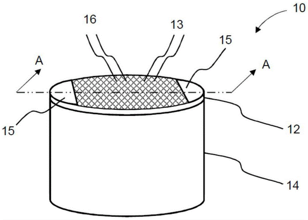
一种用于气溶胶生成系统的加热器组件(10),加热器组件包括:用于加热液体气溶胶形成基质以形成气溶胶的流体可透过加热元件(12),流体可透过加热元件包括多个孔口(16)以允许流体渗透通过加热元件(12);以及传送材料(14),所述传送材料包括用于将液体气溶胶形成基质输送到流体可透过加热元件(12)的多个孔口(16)的多个通道(18);其中传送材料(14)包括陶瓷,所述陶瓷直接沉积到流体可透过加热元件(12)的流体可透过表面上;并且其中,对于超过50%的流体可透过加热元件(12)的孔口(16),传送材料(14)包括用于将液体气溶胶形成基质输送到其相应孔口(16)的对应通道(18)。
A heater assembly (10) for an aerosol generating system, the heater assembly comprising: a fluid permeable heating element (12) for heating a liquid aerosol-forming substrate to form an aerosol, the fluid permeable heating element comprising a plurality of orifices (16) to allow fluid permeation through the heating element (12); and a delivery material (14) comprising a liquid aerosol-forming substrate for delivery to the fluid permeable heating element (12) a plurality of channels (18) of a plurality of orifices (16); wherein the transfer material (14) comprises a ceramic deposited directly onto a fluid permeable surface of the fluid permeable heating element (12); and wherein , for more than 50% fluid permeable openings (16) of the heating element (12), the delivery material (14) includes corresponding channels (18) for delivering the liquid aerosol-forming substrate to its corresponding opening (16) ).
Description
本发明涉及一种用于气溶胶生成系统的加热器组件。特别地,但不限于,本发明涉及一种用于手持式电操作气溶胶生成系统的加热器组件,其用于加热气溶胶形成基质以生成气溶胶并且用于将气溶胶递送到用户的口中。本发明还涉及用于包括加热器组件的气溶胶生成系统的筒、气溶胶生成系统以及制造加热器组件的方法。The present invention relates to a heater assembly for an aerosol generating system. In particular, but not limited to, the present invention relates to a heater assembly for a hand-held electrically operated aerosol generating system for heating an aerosol-forming substrate to generate an aerosol and for delivering the aerosol to the mouth of a user . The invention also relates to a cartridge for an aerosol generating system comprising a heater assembly, an aerosol generating system and a method of manufacturing the heater assembly.
已知手持式电操作气溶胶生成装置和系统由包括电池和控制电子器件的装置部分、用于包含或接收液体气溶胶形成基质的部分和用于加热气溶胶形成基质以生成气溶胶的电操作加热器构成。加热器通常包括线圈,该线圈围绕细长芯缠绕,该细长芯将液体气溶胶形成基质从液体储存部分转移到加热器。电流可穿过线圈以加热该加热器,并且由此从气溶胶形成基质生成气溶胶。还包括烟嘴部分,用户可在该烟嘴部分上吸气以将气溶胶抽吸到其口中。Hand-held electrically-operated aerosol-generating devices and systems are known to be operated from a device portion including batteries and control electronics, a portion for containing or receiving a liquid aerosol-forming substrate, and an electrically operated device for heating the aerosol-forming substrate to generate an aerosol Heater composition. The heater typically includes a coil wound around an elongated core that transfers the liquid aerosol-forming substrate from the liquid storage portion to the heater. Electric current may be passed through the coil to heat the heater and thereby generate an aerosol from the aerosol-forming substrate. A mouthpiece portion is also included on which the user can inhale to draw the aerosol into his mouth.
除了芯之外,液体储存部分可包括用于保持液体气溶胶形成基质的吸收材料。因此,制造用于已知气溶胶生成装置的加热器组件以及提供将液体气溶胶形成基质传送到加热丝的装置可涉及至少三个部件的组装。这增加了组装线的复杂性和所涉及的制造步骤的数目。In addition to the core, the liquid storage portion may comprise absorbent material for holding the liquid aerosol-forming matrix. Thus, fabricating a heater assembly for a known aerosol-generating device and providing a means for delivering a liquid aerosol-forming substrate to a heating wire may involve the assembly of at least three parts. This increases the complexity of the assembly line and the number of manufacturing steps involved.
如果用户在液体气溶胶形成基质已耗尽之后继续使用气溶胶生成装置,则已知气溶胶生成装置出现另一个问题。在这种情况下,已知用于形成芯吸材料的一些材料在干燥条件下加热时降解,并且释放可能具有潜在危害的不需要的副产物。而且,已知一些纤维芯吸材料在干燥条件下加热时释放纤维。Another problem with known aerosol-generating devices occurs if the user continues to use the aerosol-generating device after the liquid aerosol-forming substrate has been exhausted. In this context, some materials used to form wicking materials are known to degrade when heated in dry conditions and release unwanted by-products that may be potentially harmful. Also, some fibrous wicking materials are known to release fibers when heated under dry conditions.
期望提供一种具有较少的需要组装的部分的用于气溶胶生成系统的加热器组件。期望提供一种制造更简单的用于气溶胶生成系统的加热器组件。还期望提供一种降低产生不需要的副产物的风险的加热器组件。It would be desirable to provide a heater assembly for an aerosol generating system that has fewer parts to assemble. It would be desirable to provide a heater assembly for an aerosol generating system that is easier to manufacture. It would also be desirable to provide a heater assembly that reduces the risk of producing unwanted by-products.
根据本公开的实例,提供了一种用于气溶胶生成系统的加热器组件。加热器组件可包括用于加热液体气溶胶形成基质以形成气溶胶的流体可透过加热元件。加热器组件可包括用于将液体气溶胶形成基质输送到流体可透过加热元件的传送材料。传送材料可包括陶瓷。陶瓷可沉积到流体可透过加热元件的流体可透过表面上。陶瓷可直接沉积到流体可透过加热元件的流体可透过表面上。According to an example of the present disclosure, a heater assembly for an aerosol generating system is provided. The heater assembly may include a fluid permeable heating element for heating the liquid aerosol-forming substrate to form an aerosol. The heater assembly may include a delivery material for delivering the liquid aerosol-forming substrate to the fluid permeable heating element. The transfer material may include ceramics. The ceramic can be deposited onto the fluid permeable surface of the fluid permeable heating element. The ceramic can be deposited directly onto the fluid permeable surface of the fluid permeable heating element.
根据本公开的实例,提供了一种用于气溶胶生成系统的加热器组件,加热器组件包括:用于加热液体气溶胶形成基质以形成气溶胶的流体可透过加热元件;以及用于将液体气溶胶形成基质输送到流体可透过加热元件的传送材料,其中传送材料包括直接沉积到流体可透过加热元件的流体可透过表面上的陶瓷。According to an example of the present disclosure, there is provided a heater assembly for an aerosol generating system, the heater assembly includes: a fluid permeable heating element for heating a liquid aerosol-forming substrate to form an aerosol; The liquid aerosol-forming substrate is delivered to the delivery material of the fluid permeable heating element, wherein the delivery material comprises ceramic deposited directly onto the fluid permeable surface of the fluid permeable heating element.
如本文中所用,术语“沉积”旨在意指通过流体可透过加热元件的表面上的一些形式的物理、化学或电沉积过程来形成传送材料。术语“沉积”并不旨在涵盖将传送材料形成为仅附接到流体可透过加热元件或置于与流体可透过加热元件接触的单独分立部分。为避免疑义,术语“沉积”包括电泳沉积。As used herein, the term "deposition" is intended to mean the formation of the transfer material by some form of physical, chemical or electrodeposition process on the surface of the fluid permeable heating element. The term "deposition" is not intended to cover the formation of transfer material as a separate discrete part which is merely attached to or placed in contact with the fluid permeable heating element. For the avoidance of doubt, the term "deposition" includes electrophoretic deposition.
如本文中所用,术语“直接沉积”意指将传送材料沉积在流体可透过加热元件的表面上而与流体可透过加热元件直接接触,没有布置在传送材料与流体可透过加热元件之间的介入部件。As used herein, the term "direct deposition" means depositing the transfer material on the surface of the fluid permeable heating element in direct contact with the fluid permeable heating element, without being disposed between the transfer material and the fluid permeable heating element. intervening components.
有利地,通过将传送材料直接沉积在流体可透过加热元件上,传送材料与流体可透过加热元件一体地形成。换句话说,传送材料和流体可透过加热元件形成为单件或单个部分。加热器组件仅包括单个部件,而不是两个部件,即单独的传送材料和加热元件。这减少了必须组装的加热器组件的分立部分的数目,并且使组装更简单。其还避免了对用于组装加热器组件的其它部件(例如用于将部件保持在一起的框架或保持器)的需求。而且,加热器组件的其它部件可直接连接到加热器组件。例如,电触点可直接连接到流体可透过加热元件。另外,将流体可透过加热元件和传送材料形成为单个一体式部件确保流体可透过加热元件与传送材料流体连通,并且有助于将液体气溶胶形成基质供应到加热元件。Advantageously, the transfer material is integrally formed with the fluid permeable heating element by depositing the transfer material directly on the fluid permeable heating element. In other words, the transfer material and the fluid permeable heating element are formed as a single piece or section. The heater assembly consists of only a single component instead of two components, a separate conveying material and a heating element. This reduces the number of discrete parts of the heater assembly that must be assembled and makes assembly simpler. It also avoids the need for other components used to assemble the heater assembly, such as frames or holders to hold the components together. Also, other components of the heater assembly may be directly connected to the heater assembly. For example, the electrical contacts may be directly connected to the fluid permeable heating element. Additionally, forming the fluid permeable heating element and delivery material as a single integral part ensures that the fluid permeable heating element is in fluid communication with the delivery material and facilitates supply of the liquid aerosol-forming substrate to the heating element.
由陶瓷形成传送材料的优点在于,其减轻了使用纤维芯吸材料而可能产生的一些问题(如由干加热情况引起的不需要的副产物的产生)。与一些基于聚合物的纤维相比,陶瓷相对惰性,并且在较宽的温度范围内热稳定并且结构稳定。使用陶瓷传送材料还降低了将纤维节段释放到装置中的风险。An advantage of forming the transfer material from ceramic is that it alleviates some of the problems that can arise with the use of fibrous wicking materials (such as the generation of unwanted by-products caused by dry heating conditions). Compared with some polymer-based fibers, ceramics are relatively inert and thermally and structurally stable over a wide temperature range. Using a ceramic delivery material also reduces the risk of releasing fiber segments into the device.
流体可透过加热元件可包括从加热元件的第一侧延伸到第二侧的多个空隙或孔口。多个空隙或孔口有利地允许流体渗透通过加热元件。The fluid permeable heating element may include a plurality of voids or apertures extending from a first side of the heating element to a second side. The plurality of voids or apertures advantageously allow fluid to permeate through the heating element.
传送材料可包括用于将液体气溶胶形成基质输送到流体可透过加热元件的多个孔口的多个通道。多个通道中的每个通道可为毛细管通道,其借助于毛细管作用将液体从传送材料的一端转移到另一端。传送材料可包括任何适合的陶瓷。传送材料可包括任何合适的惰性陶瓷或生物相容性陶瓷。合适的陶瓷的实例是Al2O3、ZrO2和包括羟基磷灰石的磷酸钙陶瓷。The delivery material may comprise a plurality of channels for delivering the liquid aerosol-forming substrate to the plurality of orifices of the fluid permeable heating element. Each of the plurality of channels may be a capillary channel that transfers liquid from one end of the transfer material to the other by means of capillary action. The transfer material may comprise any suitable ceramic. The delivery material may comprise any suitable inert or biocompatible ceramic. Examples of suitable ceramics are Al2O3 , ZrO2 and calcium phosphate ceramics including hydroxyapatite .
对于流体可透过加热元件的孔口中的每个孔口,或至少对于流体可透过加热元件的孔口中的每个孔口的大多数(如超过50%),传送材料可包括用于将液体气溶胶形成基质输送到流体可透过加热元件的相应孔口的对应通道。对于超过60%,优选超过70%,并且更优选超过80%的流体可透过加热元件的孔口,传送材料可包括用于将液体气溶胶形成基质输送到流体可透过加热元件的相应孔口的对应通道。对于50%与85%之间,优选60%与85%之间,并且更优选70%与85%之间的流体可透过加热元件的孔口,传送材料可包括用于将液体气溶胶形成基质输送到流体可透过加热元件的相应孔口的对应通道。这意味着每个孔口或至少孔口中的大部分中的每个孔口具有其自身的专用通道,该通道有助于将液体气溶胶形成基质供应到流体可透过加热元件。其还意指液体气溶胶形成基质可供应到每个孔口或至少供应到孔口中的大部分。这有助于确保具有孔口的流体可透过加热元件的每个部分,或具有孔口的流体可透过加热元件的每个部分的至少大部分接收液体气溶胶形成基质的供应,并且供应物均匀地分布在流体可透过加热元件上方。For each of the orifices of the fluid permeable heating element, or at least for a majority (such as more than 50%) of each of the orifices of the fluid permeable heating element, the transfer material may include a The liquid aerosol-forming substrate is delivered to corresponding channels of the corresponding orifices of the fluid permeable heating element. For more than 60%, preferably more than 70%, and more preferably more than 80% of the orifices of the fluid permeable heating element, the delivery material may comprise corresponding holes for delivering the liquid aerosol-forming substrate to the fluid permeable heating element The corresponding channel of the mouth. For between 50% and 85%, preferably between 60% and 85%, and more preferably between 70% and 85% fluid permeable to the orifice of the heating element, the delivery material may comprise a liquid for aerosolizing the liquid The substrate is delivered to the corresponding channel of the fluid permeable corresponding orifice of the heating element. This means that each orifice, or at least a majority of the orifices, has its own dedicated channel which facilitates the supply of the liquid aerosol-forming substrate to the fluid permeable heating element. It also means that a liquid aerosol-forming substrate may be supplied to each orifice or at least to a majority of the orifices. This helps to ensure that each portion of the heating element that is fluid permeable to the orifice, or at least a majority of each portion of the heating element that is fluid permeable to the orifice, receives a supply of liquid aerosol-forming substrate, and the supply The material is evenly distributed over the fluid permeable heating element.
传送材料可具有在传送材料的第一表面与传送材料的相对的第二表面之间限定的厚度。流体可透过加热元件可布置在第一表面处,并且第二表面可布置成接收液体气溶胶形成基质。多个通道可在传送材料的第一表面与第二表面之间延伸通过传送材料的厚度。延伸通过传送材料的厚度的多个通道可有助于将液体气溶胶形成基质从液体储存部分供应到流体可透过加热元件。传送材料的厚度可在0.5mm与6mm之间。The transfer material may have a thickness defined between a first surface of the transfer material and an opposing second surface of the transfer material. The fluid permeable heating element may be arranged at the first surface, and the second surface may be arranged to receive the liquid aerosol-forming substrate. A plurality of channels may extend through the thickness of the conveyed material between the first surface and the second surface of the conveyed material. A plurality of channels extending through the thickness of the transfer material may facilitate supply of the liquid aerosol-forming substrate from the liquid storage portion to the fluid permeable heating element. The thickness of the transfer material may be between 0.5mm and 6mm.
多个通道可布置成允许液体气溶胶形成基质在传送材料的第一表面与第二表面之间沿单个方向流动。有利地,这可导致液体气溶胶形成基质更有效地转移到流体可透过加热元件。在标准多孔陶瓷材料中,孔隙以各向同性方式互连,并且液体可沿任何方向渗透通过陶瓷,并且不一定朝向加热元件。通过提供通过陶瓷的通道,帮助液体沿单个方向流动通过传送材料,即从接收到液体气溶胶形成基质的第二表面流动到流体可透过加热元件。The plurality of channels may be arranged to allow the liquid aerosol-forming substrate to flow in a single direction between the first surface and the second surface of the transfer material. Advantageously, this may result in a more efficient transfer of the liquid aerosol-forming substrate to the fluid permeable heating element. In standard porous ceramic materials, the pores are interconnected in an isotropic manner, and liquids can permeate through the ceramic in any direction, not necessarily towards the heating element. By providing channels through the ceramic, the flow of liquid through the transfer material is facilitated in a single direction, ie from the second surface of the aerosol-forming substrate receiving the liquid to the fluid permeable heating element.
多个通道可在基本上正交于传送材料的第一表面的方向上基本上线性地延伸。有利地,这可导致液体气溶胶形成基质向流体可透过加热元件的更有效的转移,因为液体正采取到流体可透过加热元件的最短路线,即直线。The plurality of channels may extend substantially linearly in a direction substantially normal to the first surface of the conveying material. Advantageously, this may result in a more efficient transfer of the liquid aerosol-forming substrate to the fluid permeable heating element, since the liquid is taking the shortest route, ie a straight line, to the fluid permeable heating element.
流体可透过加热元件的多个孔口中的每个孔口可具有在20微米与300微米之间的横截面尺寸。已发现这是允许液体气溶胶形成基质渗透到流体可透过加热元件的孔口中并且允许在由流体可透过加热元件加热时特别有效地生成气溶胶的特别有效的尺寸范围。Each of the plurality of orifices of the fluid permeable heating element may have a cross-sectional dimension of between 20 microns and 300 microns. This has been found to be a particularly effective size range to allow the liquid aerosol-forming substrate to penetrate into the orifices of the fluid permeable heating element and to allow particularly efficient generation of aerosols when heated by the fluid permeable heating element.
优选地,流体可透过加热元件的多个孔口中的每个孔口可具有在20微米与200微米之间,更优选地在20微米与100微米之间,更优选地在50微米与80微米之间,并且再更优选地约70微米的横截面尺寸。Preferably, each of the plurality of orifices of the fluid permeable heating element may have a diameter between 20 microns and 200 microns, more preferably between 20 microns and 100 microns, more preferably between 50 microns and 80 microns microns, and even more preferably about 70 microns in cross-sectional dimension.
多个通道中的每个通道沿着通道的长度的横截面尺寸可与流体可透过加热元件的孔口的横截面尺寸基本上相同。这允许液体气溶胶形成基质通过通道不受阻碍地流动。Each of the plurality of channels may have a cross-sectional dimension along the length of the channel that is substantially the same as a cross-sectional dimension of the fluid permeable orifice of the heating element. This allows the liquid aerosol-forming substrate to flow unhindered through the channels.
多个通道中的每个通道沿着通道的长度的横截面尺寸可与流体可透过加热元件的其对应孔口的横截面尺寸基本上相同。这允许液体气溶胶形成基质通过通道不受阻碍地流动。Each of the plurality of channels may have a cross-sectional dimension along the length of the channel that is substantially the same as a cross-sectional dimension of its corresponding orifice of the fluid permeable heating element. This allows the liquid aerosol-forming substrate to flow unhindered through the channels.
加热器组件可进一步包括电触点,以用于将电力供应到流体可透过加热元件。电触点可直接连接到流体可透过加热元件。有利地,通过将电触点直接连接到流体可透过加热元件,必须在组装线上组装并且连接的部件的数目进一步减少。The heater assembly may further include electrical contacts for supplying electrical power to the fluid permeable heating element. The electrical contacts can be connected directly to the fluid permeable heating element. Advantageously, by connecting the electrical contacts directly to the fluid permeable heating element, the number of parts that have to be assembled and connected on the assembly line is further reduced.
电触点可定位在流体可透过加热元件的相对端上。电接触部分可包括两个导电接触垫。导电接触垫可定位于流体可通过加热元件的边缘区域处。优选地,至少两个导电接触垫可定位于加热元件的端部上。导电接触垫可直接固定到流体可透过加热元件的导电细丝。导电接触垫可包括锡贴片。备选地,导电接触垫可与流体可透过的加热元件成一体。Electrical contacts may be positioned on opposite ends of the fluid permeable heating element. The electrical contact portion may include two conductive contact pads. Conductive contact pads may be positioned at edge regions where fluid may pass through the heating element. Preferably, at least two electrically conductive contact pads are positionable on the ends of the heating element. The conductive contact pads may be secured directly to the conductive filaments of the fluid permeable heating element. The conductive contact pads may include tin pads. Alternatively, the electrically conductive contact pads may be integral with the fluid permeable heating element.
传送材料可包括布置在流体可透过加热元件的第一侧上的第一传送材料。加热器组件可进一步包括布置在流体可透过加热元件的第二侧上的第二传送材料。这有效地将流体可透过加热元件夹在第一传送材料与第二传送材料之间,这可有助于改进加热器组件的稳健性。The transfer material may include a first transfer material disposed on the first side of the fluid permeable heating element. The heater assembly may further include a second transfer material disposed on the second side of the fluid permeable heating element. This effectively sandwiches the fluid permeable heating element between the first transfer material and the second transfer material, which can help improve the robustness of the heater assembly.
流体可透过加热元件可包括电阻加热元件。The fluid permeable heating element may comprise a resistive heating element.
流体可透过加热元件可由任何适合的导电材料形成。合适的材料包括但不限于:半导体(如掺杂陶瓷)、“导电”陶瓷(如二硅化钼)、碳、石墨、金属、金属合金和由陶瓷材料和金属材料制成的复合材料。此类复合材料可包括掺杂或无掺杂的陶瓷。适合的掺杂陶瓷的实例包括掺杂碳化硅。适合的金属的实例包括钛、锆、钽和铂族金属。适合的金属合金的实例包括不锈钢;康铜;含镍合金、含钴合金、含铬合金、含铝合金、含钛合金、含锆合金、含铪合金、含铌合金、含钼合金、含钽合金、含钨合金、含锡合金、含镓合金、含锰合金和含铁合金;以及基于镍、铁、钴的超级合金;不锈钢、

另外,流体可透过加热元件可包括上述材料的组合。可使用材料的组合来改善对基本平坦的加热元件的阻力的控制。例如,具有高固有电阻的材料可与具有低固有电阻的材料组合。如果其中一种材料更有利于其他方面,例如价格、可加工性或其他物理和化学参数,则这可能是有利的。有利的是,高电阻率加热器允许更有效地使用电池能量。Additionally, the fluid permeable heating element may comprise combinations of the above materials. Combinations of materials may be used to improve control of the resistance of the substantially planar heating element. For example, a material with a high intrinsic resistance can be combined with a material with a low intrinsic resistance. It may be advantageous if one of the materials is more advantageous in other respects, such as price, processability or other physical and chemical parameters. Advantageously, a high resistivity heater allows for more efficient use of battery energy.
流体可透过加热元件可包括基本上平坦的加热元件,以允许简单的制造。几何学上,术语“基本上平坦的”加热元件用于指呈基本上二维拓扑歧管形式的加热元件。在一些实例中,基本上平坦的加热元件可基本上沿着表面在两个维度上而非在第三维度上延伸。在一些实例中,基本上平坦的加热元件在表面内的两个维度上的尺寸可以是在垂直于所述表面的第三维度上的尺寸的至少五倍大。在一些实例中,基本上平坦的流体可透过加热元件可包括两个基本上假想的平行平坦表面。在一些实例中,基本上平坦的加热元件可为两个基本上假想的平行平坦表面之间的结构,其中这两个假想表面之间的距离基本上小于平面内的延伸部分。在一些实例中,两个基本上假想的平行表面中的仅一个可为平坦的。在一些实例中,基本上平坦的加热元件可为平面的。在其它实例中,基本上平坦的加热元件可沿着一个或多个维度弯曲,例如形成圆拱形状或桥形状。The fluid permeable heating element may comprise a substantially planar heating element to allow simple manufacture. Geometrically, the term "substantially planar" heating element is used to refer to a heating element in the form of a substantially two-dimensional topological manifold. In some examples, the substantially planar heating element may extend substantially along the surface in two dimensions rather than in a third dimension. In some examples, the dimensions of the substantially planar heating element in two dimensions within the surface may be at least five times larger than in the third dimension perpendicular to the surface. In some examples, a substantially planar fluid permeable heating element may include two substantially imaginary parallel planar surfaces. In some examples, the substantially planar heating element may be a structure between two substantially imaginary parallel planar surfaces, wherein the distance between the two imaginary surfaces is substantially less than the in-plane extension. In some examples, only one of the two substantially imaginary parallel surfaces may be flat. In some examples, the substantially planar heating element can be planar. In other examples, a substantially planar heating element may be curved along one or more dimensions, eg, forming a dome shape or a bridge shape.
流体可透过加热元件可包括一根或多根导电细丝。术语“细丝”用于指代布置于两个电触头之间的电路径。细丝可任意地分叉并分别分成若干路径或细丝,或者可从几个电路径汇聚成一个路径。细丝可具有圆形、正方形、扁平或任何其他形式的横截面。细丝可以直线或弯曲的方式布置。The fluid permeable heating element may comprise one or more conductive filaments. The term "filament" is used to refer to an electrical path arranged between two electrical contacts. The filaments may fork at will and separate into several paths or filaments respectively, or several electrical paths may converge into one path. The filaments may have a round, square, flat or any other form of cross-section. The filaments can be arranged in a straight or curved fashion.
流体可透过加热元件可为例如彼此平行布置的细丝的阵列。优选的是,细丝可形成网。网可为织造或非织造的。网可使用不同类型的编织或网格结构来形成。备选地,导电加热元件包括细丝的阵列或细丝的织物。导电细丝的网格、阵列或织物的特征还在于其保持液体的能力。The fluid permeable heating element may be, for example, an array of filaments arranged parallel to each other. Preferably, the filaments form a web. Mesh can be woven or nonwoven. Meshes can be formed using different types of weave or mesh structures. Alternatively, the electrically conductive heating element comprises an array of filaments or a fabric of filaments. A grid, array or fabric of conductive filaments is also characterized by its ability to retain liquid.
在优选的实例中,基本上平坦的加热元件可由形成为线材网格的线材构造。优选的是,网格采用平纹编织设计。优选地,加热元件是由网状条制成的线格栅。In a preferred example, the substantially planar heating element may be constructed from wires formed as a grid of wires. Preferably, the mesh is of a plain weave design. Preferably, the heating element is a wire grid made of mesh strips.
导电细丝可限定细丝之间的空隙,并且所述空隙可具有在10微米与100微米之间的宽度。优选地,细丝引起空隙中的毛细管作用,使得在使用时,要蒸发的液体被抽吸到空隙中,从而增加加热元件与液体气溶胶形成基质之间的接触面积。The conductive filaments may define voids between the filaments, and the voids may have a width between 10 microns and 100 microns. Preferably, the filaments induce capillary action in the void such that in use liquid to be evaporated is drawn into the void thereby increasing the contact area between the heating element and the liquid aerosol-forming substrate.
导电细丝可形成大小在每厘米60与240根细丝(+/-10%)之间的网格。优选地,网格密度在每厘米100与140根细丝(+/-10%)之间。更优选的是,网密度为每厘米大约115根细丝。空隙的宽度可在20微米与300微米之间,优选地在50微米与100微米之间,更优选地是大约70微米。作为空隙的面积与网格的总面积的比率的网格的开放区域的百分比可在40%与90%之间,优选地在85%与80%之间,更优选地是大约82%。The conductive filaments can form a mesh size between 60 and 240 filaments per centimeter (+/- 10%). Preferably, the grid density is between 100 and 140 filaments per centimeter (+/- 10%). More preferably, the web density is about 115 filaments per centimeter. The width of the voids may be between 20 microns and 300 microns, preferably between 50 microns and 100 microns, more preferably about 70 microns. The percentage of open area of the mesh, which is the ratio of the area of the voids to the total area of the mesh, may be between 40% and 90%, preferably between 85% and 80%, more preferably about 82%.
导电细丝的宽度或直径可在10微米与100微米之间,优选地在10微米与50微米之间,更优选地在12微米与25微米之间,并且最优选地是大约16微米。细丝可具有圆形的横截面或者可具有平坦的横截面。The width or diameter of the conductive filaments may be between 10 and 100 microns, preferably between 10 and 50 microns, more preferably between 12 and 25 microns, and most preferably about 16 microns. The filaments may have a circular cross-section or may have a flat cross-section.
导电细丝的网格、阵列或织物的面积可能较小,例如,小于或等于50平方毫米,优选地小于或等于25平方毫米,更优选地是大约15平方毫米。如此选择大小以将加热元件并入到手持式系统中。将导电细丝的网格、阵列或织物的大小设定成小于或等于50平方毫米会减少加热导电细丝的网格、阵列或织物所需的总功率量,同时仍然确保导电细丝的网格、阵列或织物与液体气溶胶形成基质充分接触。导电细丝的网格、阵列或织物可例如是矩形,并且具有在2毫米到10毫米之间的长度以及在2毫米到10毫米之间的宽度。优选地,网格具有大约5毫米乘以3毫米的尺寸。The area of the grid, array or weave of conductive filaments may be relatively small, for example, less than or equal to 50 square millimeters, preferably less than or equal to 25 square millimeters, more preferably about 15 square millimeters. The size is chosen so as to incorporate the heating element into the handheld system. Sizing the grid, array, or fabric of conductive filaments to be less than or equal to 50 square millimeters reduces the overall amount of power required to heat the grid, array, or fabric of conductive filaments while still ensuring that the grid, array, or fabric of conductive filaments The lattice, array or fabric is in substantial contact with the liquid aerosol-forming substrate. The grid, array or fabric of conductive filaments may eg be rectangular and have a length of between 2 mm and 10 mm and a width of between 2 mm and 10 mm. Preferably, the grid has dimensions of approximately 5 millimeters by 3 millimeters.
优选地,细丝由线材制成。更优选地,线材由金属制成,最优选地由不锈钢制成。Preferably, the filaments are made of wire. More preferably, the wire is made of metal, most preferably stainless steel.
加热元件的导电细丝的网格、阵列或织物的电阻可在0.3欧姆与4欧姆之间。优选地,电阻等于或大于0.5欧姆。更优选地,导电细丝的网格、阵列或织物的电阻在0.6欧姆与0.8欧姆之间,且最优选地是约0.68欧姆。导电细丝的网格、阵列或织物的电阻优选的是比任何导电接触部分的电阻大至少一个数量级,且更优选的是大至少两个数量级。这确保了通过使电流通过加热元件而生成的热集中到导电细丝的网或阵列。如果系统由电池供电,那么加热元件具有较低总电阻是有利的。低电阻高电流系统允许向加热元件递送高功率。这允许加热元件快速地将导电细丝加热到所要温度。The electrical resistance of the grid, array or fabric of conductive filaments of the heating element may be between 0.3 ohms and 4 ohms. Preferably, the resistance is equal to or greater than 0.5 ohms. More preferably, the electrical resistance of the grid, array or fabric of conductive filaments is between 0.6 ohms and 0.8 ohms, and most preferably about 0.68 ohms. The resistance of the grid, array or fabric of conductive filaments is preferably at least one order of magnitude greater, and more preferably at least two orders of magnitude greater than the resistance of any conductive contact portion. This ensures that the heat generated by passing electrical current through the heating element is concentrated to the web or array of conductive filaments. If the system is powered by batteries, it is advantageous that the heating element has a lower overall resistance. A low resistance high current system allows high power to be delivered to the heating element. This allows the heating element to quickly heat the conductive filament to the desired temperature.
备选地,流体可透过加热元件可包括其中形成有孔口阵列的加热板或膜。例如,孔口可通过蚀刻或加工来形成。板或膜可由具有合适电特性的任何材料(如上文关于流体可透过加热元件描述的材料)形成。Alternatively, the fluid permeable heating element may comprise a heating plate or membrane having an array of orifices formed therein. For example, apertures may be formed by etching or machining. The plate or membrane may be formed from any material having suitable electrical properties, such as those described above in relation to the fluid permeable heating element.
根据本公开的另一实例,提供了一种用于气溶胶生成系统的筒。筒可包括根据上述示例性加热器组件中的任一个的加热器组件。筒可包括用于保持液体气溶胶形成基质的液体储存部分或隔室。According to another example of the present disclosure, a cartridge for an aerosol generating system is provided. The cartridge may include a heater assembly according to any of the exemplary heater assemblies described above. The cartridge may comprise a liquid storage portion or compartment for holding a liquid aerosol-forming substrate.
根据本公开的另一个实例,提供了一种用于气溶胶生成系统的筒,筒包括根据上述示例性加热器组件中的任一个的加热器组件和用于保持液体气溶胶形成基质的液体储存部分或隔室。According to another example of the present disclosure, there is provided a cartridge for an aerosol generating system, the cartridge comprising a heater assembly according to any one of the above exemplary heater assemblies and a liquid storage for holding a liquid aerosol-forming substrate section or compartment.
术语“液体储存部分”和“液体储存隔室”在本文中可互换使用。液体储存部分或隔室可具有与彼此连通的第一储存部分和第二储存部分。液体储存隔室的第一储存部分可位于加热器组件的与液体储存隔室的第二储存部分相对的一侧上。液体气溶胶形成基质保持在液体储存隔室的第一储存部分和第二储存部分两者中。The terms "liquid storage portion" and "liquid storage compartment" are used interchangeably herein. The liquid storage portion or compartment may have a first storage portion and a second storage portion in communication with each other. The first storage portion of the liquid storage compartment may be located on an opposite side of the heater assembly from the second storage portion of the liquid storage compartment. The liquid aerosol-forming substrate is held in both the first storage portion and the second storage portion of the liquid storage compartment.
有利地,储存隔室的第一储存部分大于液体储存隔室的第二储存部分。筒可构造成允许用户在筒上进行抽吸或吮吸以便吸入在筒中生成的气溶胶。在使用中,筒的口端开口通常定位于加热器组件的上方,其中储存隔室的第一储存部分定位于口端开口与加热器组件之间。使液体储存隔室的第一储存部分大于液体储存隔室的第二储存部分确保了在使用期间,在重力的影响下,液体从液体储存隔室的第一储存部分递送到液体储存隔室的第二储存部分,并且因此到加热器组件。Advantageously, the first storage portion of the storage compartment is larger than the second storage portion of the liquid storage compartment. The cartridge may be configured to allow a user to draw or suck on the cartridge to inhale an aerosol generated in the cartridge. In use, the mouth end opening of the cartridge is generally positioned above the heater assembly, with the first storage portion of the storage compartment being positioned between the mouth end opening and the heater assembly. Making the first storage portion of the liquid storage compartment larger than the second storage portion of the liquid storage compartment ensures that, during use, liquid is delivered from the first storage portion of the liquid storage compartment to the bottom of the liquid storage compartment under the influence of gravity. the second storage section, and thus to the heater assembly.
筒可具有口端和连接端,用户可通过所述口端抽吸生成的气溶胶,所述连接端构造成连接到气溶胶生成装置,其中加热器组件的第一侧面向口端,并且加热器组件的第二侧面向连接端。The cartridge can have a mouth end through which a user can inhale the generated aerosol and a connection end configured to connect to an aerosol generating device, wherein the first side of the heater assembly faces the mouth end and heats the The second side of the connector assembly faces the connection end.
筒可限定从空气入口经过加热器组件的第一侧到筒的口端开口的封闭气流路径或通路。封闭气流通路可穿过液体储存隔室的第一或第二储存部分。在一个实施例中,气流路径在液体储存隔室的第一储存部分与第二储存部分之间延伸。另外,气流通路可延伸通过液体储存隔室的第一储存部分。例如,液体储存隔室的第一储存部分可具有环形横截面,其中气流通路从加热器组件通过液体储存隔室的第一储存部分延伸到口端部分。备选地,气流通路可从加热器组件延伸到邻近于液体储存隔室的第一储存部分的口端开口。The cartridge may define a closed airflow path or passageway from the air inlet through the first side of the heater assembly to the mouth opening of the cartridge. The closed air flow path may pass through the first or second storage portion of the liquid storage compartment. In one embodiment, the airflow path extends between the first storage portion and the second storage portion of the liquid storage compartment. Additionally, the air flow passage may extend through the first storage portion of the liquid storage compartment. For example, the first storage portion of the liquid storage compartment may have an annular cross-section, wherein the air flow path extends from the heater assembly through the first storage portion of the liquid storage compartment to the mouth end portion. Alternatively, the air flow path may extend from the heater assembly to the mouth opening of the first storage portion adjacent to the liquid storage compartment.
替代性地或者另外,筒可包含用于容纳液体气溶胶形成基质的保持材料。保持材料可在液体储存隔室的第一储存部分、液体储存隔室的第二储存部分或液体储存隔室的第一储存部分和第二储存部分两者中。保持材料可为泡沫、海绵或纤维集合。保持材料可由聚合物或共聚物形成。在一个实施例中,保持材料是纺丝聚合物。液体气溶胶形成基质可在使用期间释放到保持材料中。例如,可将液体气溶胶形成基质设置在胶囊中。Alternatively or additionally, the cartridge may comprise a retaining material for containing the liquid aerosol-forming substrate. The retention material may be in the first storage portion of the liquid storage compartment, the second storage portion of the liquid storage compartment, or both the first and second storage portions of the liquid storage compartment. The retention material can be foam, sponge or a collection of fibers. The retention material can be formed from polymers or copolymers. In one embodiment, the retention material is a spun polymer. The liquid aerosol-forming substrate can be released into the retention material during use. For example, a liquid aerosol-forming substrate may be provided in a capsule.
筒有利地包含液体气溶胶形成基质。如本文中所用,术语“气溶胶形成基质”是指能够释放可形成气溶胶的挥发性化合物的基质。可通过加热气溶胶形成基质来释放挥发性化合物。The cartridge advantageously contains a liquid aerosol-forming substrate. As used herein, the term "aerosol-forming substrate" refers to a substrate capable of releasing an aerosol-forming volatile compound. Volatile compounds can be released by heating the aerosol-forming substrate.
气溶胶形成基质在室温下可为液态的。气溶胶形成基质可包括液体和固体组分两者。液体气溶胶形成基质可包括尼古丁。包含液体气溶胶形成基质的尼古丁可为尼古丁盐基质。液体气溶胶形成基质可包括植物基质料。液体气溶胶形成基质可包括烟草。液体气溶胶形成基质可包括含有挥发性烟草香味化合物的含烟草材料,所述材料在加热后即从气溶胶形成基质释放。液体气溶胶形成基质可包括均质化的烟草材料。液体气溶胶形成基质可包括不含烟草的材料。液体气溶胶形成基质可包括均质化的植物基材料。The aerosol-forming substrate may be liquid at room temperature. Aerosol-forming substrates may comprise both liquid and solid components. The liquid aerosol-forming substrate may include nicotine. The nicotine comprising a liquid aerosol-forming matrix may be a nicotine salt matrix. Liquid aerosol-forming substrates may include plant-based materials. The liquid aerosol-forming substrate may include tobacco. The liquid aerosol-forming substrate may comprise a tobacco-containing material containing volatile tobacco flavor compounds that is released from the aerosol-forming substrate upon heating. The liquid aerosol-forming substrate may comprise homogenized tobacco material. The liquid aerosol-forming substrate may comprise a tobacco-free material. The liquid aerosol-forming substrate may comprise a homogenized plant-based material.
液体气溶胶形成基质可包括一种或多种气溶胶形成剂。气溶胶形成物是任何适合的已知化合物或化合物的混合物,该化合物在使用中有利于形成致密且稳定的气溶胶并且在系统的操作温度下基本上耐热降解。适合的气溶胶形成剂的实例包括丙三醇和丙二醇。适合的气溶胶形成剂是本领域众所周知的,并且包括但不限于:多元醇,例如三甘醇,1,3-丁二醇和甘油;多元醇的酯,例如甘油单、二或三乙酸酯;和一元、二元或多元羧酸的脂肪酸酯,例如二甲基十二烷二酸酯和二甲基十四烷二酸酯。液体气溶胶形成基质可包括水、溶剂、乙醇、植物提取物和天然或人工调味剂。The liquid aerosol-forming substrate may comprise one or more aerosol-forming agents. The aerosol former is any suitable known compound or mixture of compounds which, in use, facilitates the formation of a dense and stable aerosol and is substantially resistant to thermal degradation at the operating temperature of the system. Examples of suitable aerosol formers include glycerol and propylene glycol. Suitable aerosol-forming agents are well known in the art and include, but are not limited to: polyols such as triethylene glycol, 1,3-butanediol and glycerol; esters of polyols such as glycerol mono-, di- or triacetate ; and fatty acid esters of monobasic, dibasic or polycarboxylic acids, such as dimethyldodecanedioate and dimethyltetradecanedioate. Liquid aerosol-forming substrates can include water, solvents, ethanol, plant extracts and natural or artificial flavoring agents.
液体气溶胶形成基质可包括尼古丁和至少一种气溶胶形成剂。气溶胶形成剂可为丙三醇或丙二醇。气溶胶形成剂可包括丙三醇和丙二醇两者。液体气溶胶形成基质可具有在约0.5%到约10%之间,例如为约2%的尼古丁浓度。The liquid aerosol-forming base may comprise nicotine and at least one aerosol-forming agent. The aerosol forming agent may be glycerol or propylene glycol. Aerosol forming agents may include both glycerol and propylene glycol. The liquid aerosol-forming substrate may have a nicotine concentration of between about 0.5% and about 10%, for example about 2%.
筒可包括壳体。壳体可由可模制的塑料材料形成,所述塑料材料例如是聚丙烯(PP)或聚对苯二甲酸乙二醇酯(PET)。壳体可形成液体存储隔室的一个或两个部分的壁的部分或全部。壳体和液体存储隔室可一体地形成。备选地,液体存储隔室可与壳体分开形成,并且组装到壳体。The cartridge can include a housing. The housing may be formed from a moldable plastic material such as polypropylene (PP) or polyethylene terephthalate (PET). The housing may form part or all of the walls of one or both parts of the liquid storage compartment. The housing and the liquid storage compartment may be integrally formed. Alternatively, the liquid storage compartment may be formed separately from the housing and assembled to the housing.
根据本公开的另一实例,提供了一种气溶胶生成系统。气溶胶生成系统可包括根据上述示例性筒中的任一个的筒。气溶胶生成系统可包括气溶胶生成装置。所述筒可可移除地联接到气溶胶生成装置。气溶胶生成装置可包括用于加热器组件的电源。According to another example of the present disclosure, an aerosol generating system is provided. The aerosol generating system may comprise a cartridge according to any of the exemplary cartridges described above. The aerosol generating system may include an aerosol generating device. The cartridge is removably coupleable to the aerosol-generating device. The aerosol-generating device may include a power source for the heater assembly.
根据本公开的另一个实例,提供了一种气溶胶生成系统,所述气溶胶生成系统包括:根据上述示例性筒中的任一个的筒;以及气溶胶生成装置,其中筒可移除地联接到气溶胶生成装置,并且其中气溶胶生成装置包括用于加热器组件的电源。According to another example of the present disclosure, there is provided an aerosol generating system comprising: a cartridge according to any one of the above exemplary cartridges; and an aerosol generating device, wherein the cartridge is removably coupled to An aerosol-generating device, and wherein the aerosol-generating device includes a power source for the heater assembly.
气溶胶生成装置可进一步包括控制电路,所述控制电路配置成控制对加热器组件的电力供应。The aerosol-generating device may further include a control circuit configured to control power supply to the heater assembly.
控制电路系统可包括微处理器。微处理器可为可编程微处理器、微控制器或专用一体化芯片(ASIC)或能够提供控制的其它电路系统。控制电路系统可包括其它电子部件。例如,在一些实施例中,控制电路可包括传感器、开关、显示元件中的任一个。电力可在激活装置之后连续地供应到加热器组件,或者可间歇地供应,如在逐口吸气的基础上。电力可例如借助于脉冲宽度调制(PWM)以电流脉冲的形式供应到加热器组件。The control circuitry may include a microprocessor. The microprocessor may be a programmable microprocessor, microcontroller or application specific all-in-one chip (ASIC) or other circuitry capable of providing control. The control circuitry may include other electronic components. For example, in some embodiments, the control circuitry may include any of sensors, switches, and display elements. Power may be supplied to the heater assembly continuously after activation of the device, or may be supplied intermittently, such as on a puff-by-puff basis. Power may be supplied to the heater assembly in the form of current pulses, for example by means of pulse width modulation (PWM).
电源可为DC电源。电源可为电池。电池可为基于锂的电池,例如锂钴、锂铁磷酸盐、钛酸锂或锂聚合物电池。电池可为镍金属氢化物电池或镍镉电池。电源可为另一形式的电荷储存装置,例如,电容器。电源可为再充电的,并且针对许多充放电循环而配置。电源可具有允许储存足以用于一次或多次用户体验的能量的容量;例如,电源可具有足够的容量以允许连续生成气溶胶持续约六分钟的时间,对应于抽一支常规卷烟所耗费的典型时间,或者持续是六分钟的倍数的时间。在另一个实例中,电源可具有足够的容量以允许预定数量的吸气或加热器组件的不连续启动。The power source may be a DC power source. The power source can be a battery. The battery may be a lithium based battery such as lithium cobalt, lithium iron phosphate, lithium titanate or lithium polymer battery. The battery can be a nickel metal hydride battery or a nickel cadmium battery. The power source may be another form of charge storage device, such as a capacitor. The power supply may be rechargeable and configured for many charge and discharge cycles. The power supply may have a capacity to allow storage of energy sufficient for one or more user experiences; for example, the power supply may have sufficient capacity to allow continuous generation of aerosols for a period of approximately six minutes, corresponding to the time it takes to smoke a conventional cigarette. A typical time, or a time that lasts in multiples of six minutes. In another example, the power supply may have sufficient capacity to allow a predetermined number of discrete activations of the suction or heater assemblies.
气溶胶生成装置可包括外壳。壳体可为细长的。壳体可包括任何合适的材料或材料的组合。适合的材料的实例包括金属、合金、塑料或包含那些材料中的一种或多种的复合材料,或适用于食物或药物应用的热塑性材料,例如聚丙烯、聚醚醚酮(PEEK)和聚乙烯。优选地,材料轻质并且无脆性。The aerosol-generating device may include a housing. The housing can be elongated. The housing may comprise any suitable material or combination of materials. Examples of suitable materials include metals, alloys, plastics or composite materials comprising one or more of those materials, or thermoplastic materials suitable for food or pharmaceutical applications such as polypropylene, polyetheretherketone (PEEK) and polythene vinyl. Preferably, the material is lightweight and non-brittle.
气溶胶生成系统可为手持式气溶胶生成系统。气溶胶生成系统可为手持式气溶胶生成系统,其配置成允许用户在烟嘴上吸气以通过口端开口抽吸气溶胶。气溶胶生成系统可具有与常规雪茄或香烟相当的尺寸。气溶胶生成系统可具有在约30mm与约150mm之间的总长度。气溶胶生成系统可具有在约5mm与约30mm之间的外径。The aerosol generating system may be a handheld aerosol generating system. The aerosol-generating system may be a hand-held aerosol-generating system configured to allow a user to inhale over the mouthpiece to draw the aerosol through the mouthport opening. The aerosol generating system may be of comparable size to a conventional cigar or cigarette. The aerosol generating system may have an overall length of between about 30mm and about 150mm. The aerosol generating system may have an outer diameter of between about 5mm and about 30mm.
根据本公开的另一个实例,提供了一种制造用于气溶胶生成系统的加热器组件的方法。该方法可包括提供流体可透过加热元件。该方法可包括提供用于将液体气溶胶形成基质传送到流体可透过加热元件的传送材料。可通过将陶瓷沉积在流体可透过加热元件上而提供传送材料。可通过将陶瓷直接沉积在流体可透过加热元件上而提供传送材料。According to another example of the present disclosure, a method of manufacturing a heater assembly for an aerosol generating system is provided. The method may include providing a fluid permeable heating element. The method may include providing a transfer material for transferring the liquid aerosol-forming substrate to the fluid permeable heating element. The delivery material may be provided by depositing a ceramic on the fluid permeable heating element. The delivery material may be provided by depositing the ceramic directly on the fluid permeable heating element.
根据本公开的另一个实例,提供了一种制造用于气溶胶生成系统的加热器组件的方法,该方法包括:提供流体可透过加热元件,提供用于将液体气溶胶形成基质传送到流体可透过加热元件的传送材料;其中通过将陶瓷直接沉积在流体可透过加热元件上而提供传送材料。According to another example of the present disclosure, there is provided a method of manufacturing a heater assembly for an aerosol generating system, the method comprising: providing a fluid permeable heating element, providing a A transfer material permeable to a heating element; wherein the transfer material is provided by depositing a ceramic directly on the fluid permeable heating element.
有利地,通过将传送材料直接沉积在流体可透过加热元件上,传送材料与流体可透过加热元件一体地形成。换句话说,传送材料和流体可透过加热元件形成为单件或单个部分。传送材料和流体可透过加热元件在单个制造步骤中形成为单件或单个部分。加热器组件仅包括单个部件,而不是两个部件,即单独的传送材料和加热元件。这减少了必须组装的加热器组件的分立部分的数目,并且使组装更简单。其还避免了对用于组装加热器组件的其它部件(例如用于将部件保持在一起的框架或保持器)的需求。而且,加热器组件的其它部件可直接连接到加热器组件。例如,电触点可直接连接到流体可透过加热元件。Advantageously, the transfer material is integrally formed with the fluid permeable heating element by depositing the transfer material directly on the fluid permeable heating element. In other words, the transfer material and the fluid permeable heating element are formed as a single piece or section. Transfer material and fluids may be formed as a single piece or section through the heating element in a single manufacturing step. The heater assembly consists of only a single component instead of two components, a separate conveying material and a heating element. This reduces the number of discrete parts of the heater assembly that must be assembled and makes assembly simpler. It also avoids the need for other components used to assemble the heater assembly, such as frames or holders to hold the components together. Also, other components of the heater assembly may be directly connected to the heater assembly. For example, the electrical contacts may be directly connected to the fluid permeable heating element.
传送材料可通过电泳沉积而直接沉积到流体可透过加热元件上。The transfer material may be deposited directly onto the fluid permeable heating element by electrophoretic deposition.
如本文中所用,术语“电泳沉积”是指其中悬浮在液体介质中的胶体颗粒在电场(电泳)的影响下迁移并且沉积到导电基材(如充当电极的流体可透过加热元件)上的过程。As used herein, the term "electrophoretic deposition" refers to a process in which colloidal particles suspended in a liquid medium migrate under the influence of an electric field (electrophoresis) and deposit onto a conductive substrate such as a fluid permeable heating element acting as an electrode. process.
电泳沉积可帮助将许多特性赋予加热器组件。有利地,陶瓷传送材料结合到流体可透过加热元件,以产生单件式加热器组件,所述单件式加热器组件包括流体可透过加热元件和一体的传送材料。陶瓷传送材料将以下覆流体可透过加热元件的形状沉积,所述流体可透过加热元件在电泳沉积过程中充当电极。而且,随着沉积陶瓷层的厚度在沉积过程期间增加,沉积的陶瓷传送材料将保持该形状。因此,陶瓷传送材料将具有远离流体可透过加热元件延伸的基本上线性的通道。通道将具有与流体可透过加热元件中的下覆孔口基本上相同的形状和尺寸。因此,通道将允许通过毛细管作用通过传送材料朝向流体可透过加热元件的单向液体流动。Electrophoretic deposition can help impart many properties to heater components. Advantageously, the ceramic transfer material is bonded to the fluid permeable heating element to produce a one-piece heater assembly comprising the fluid permeable heating element and the integral transfer material. The ceramic delivery material will be deposited in the shape of an underlying fluid permeable heating element that acts as an electrode during the electrophoretic deposition process. Also, as the thickness of the deposited ceramic layer increases during the deposition process, the deposited ceramic delivery material will maintain this shape. Thus, the ceramic delivery material will have a substantially linear channel extending away from the fluid permeable heating element. The channel will have substantially the same shape and size as the underlying aperture in the fluid permeable heating element. Thus, the channels will allow unidirectional liquid flow through the transfer material towards the fluid permeable heating element by capillary action.
传送材料可通过将陶瓷颗粒沉积到流体可透过加热元件上而沉积,其中陶瓷颗粒的平均粒度在0.05微米与0.7微米之间。已发现陶瓷颗粒的该粒度范围对于产生具有合适特性的传送材料特别有效。The transfer material may be deposited by depositing ceramic particles onto the fluid permeable heating element, wherein the ceramic particles have an average particle size between 0.05 microns and 0.7 microns. This particle size range of ceramic particles has been found to be particularly effective for producing a transfer material with suitable properties.
陶瓷颗粒的粒度可取决于所使用的陶瓷的类型。例如,对于诸如Al2O3和ZrO2的惰性陶瓷,粒度可在0.2微米与0.7微米之间。对于诸如羟基磷灰石的生物相容性陶瓷,粒度可在50纳米至600纳米之间。The size of the ceramic particles can depend on the type of ceramic used. For example, for inert ceramics such as Al2O3 and ZrO2 , the particle size may be between 0.2 microns and 0.7 microns. For biocompatible ceramics such as hydroxyapatite, the particle size can be between 50 nm and 600 nm.
该方法可使用不同类型的陶瓷颗粒在沉积的传送材料内积累不同的陶瓷层。可使用不同类型的陶瓷来赋予传送材料不同的特性。The method can use different types of ceramic particles to build up different ceramic layers within the deposited transfer material. Different types of ceramics can be used to impart different properties to the delivery material.
该方法可进一步包括在已沉积传送材料之后使加热器组件退火。该方法可进一步包括在已沉积传送材料之后烧结加热器组件。烧结使陶瓷颗粒聚结,并且减小陶瓷颗粒之间的孔隙或空间。这可有助于减少液体气溶胶形成基质从通道通过陶瓷的本体的横向流出,并且改为将液体气溶胶形成基质保持在通道中,使得液体在通道中有效地流动到流体可透过加热元件中的孔口。The method may further include annealing the heater assembly after the delivery material has been deposited. The method may further include sintering the heater assembly after the delivery material has been deposited. Sintering coalesces the ceramic particles and reduces the pores or spaces between the ceramic particles. This can help reduce lateral outflow of the liquid aerosol-forming substrate from the channel through the body of the ceramic and instead retain the liquid aerosol-forming substrate in the channel so that liquid flows efficiently in the channel to the fluid permeable heating element in the orifice.
本发明在权利要求书中限定。然而,下文提供了非限制性实施例的非详尽列表。这些实施例的任何一个或多个特征可与本文描述的另一个实施例、实施方案或方面的任何一个或多个特征组合。The invention is defined in the claims. However, a non-exhaustive list of non-limiting examples is provided below. Any one or more features of these examples may be combined with any one or more features of another example, implementation or aspect described herein.
实例Ex1:一种用于气溶胶生成系统的加热器组件,所述加热器组件包括:用于加热液体气溶胶形成基质以形成气溶胶的流体可透过加热元件;以及用于将液体气溶胶形成基质输送到所述流体可透过加热元件的传送材料。Example Ex 1: A heater assembly for an aerosol generating system, said heater assembly comprising: a fluid permeable heating element for heating a liquid aerosol-forming substrate to form an aerosol; A transfer material forming the substrate is delivered to the fluid permeable heating element.
实例Ex2:根据实例Ex1的加热器组件,其中所述传送材料包括直接沉积到所述流体可透过加热元件的流体可透过表面上的陶瓷。Example Ex2: The heater assembly according to example Exl, wherein said transfer material comprises ceramic deposited directly onto a fluid permeable surface of said fluid permeable heating element.
实例Ex3:根据实例Ex1或实例Ex2的加热器组件,其中所述流体可透过加热元件包括多个孔口以允许流体渗透通过所述加热元件。Example Ex3: The heater assembly according to Example Ex1 or Example Ex2, wherein the fluid permeable heating element comprises a plurality of orifices to allow fluid to permeate through the heating element.
实例Ex4:根据实例Ex3的加热器组件,其中所述传送材料包括用于将液体气溶胶形成基质输送到所述流体可透过加热元件的多个孔口的多个通道。Example Ex4: The heater assembly according to Example Ex3, wherein said delivery material comprises a plurality of channels for delivering a liquid aerosol-forming substrate to a plurality of orifices of said fluid permeable heating element.
实例Ex5:根据实例Ex4的加热器组件,其中对于所述流体可透过加热元件的孔口中的每个孔口,所述传送材料包括用于将液体气溶胶形成基质输送到所述流体可透过加热元件的相应孔口的对应通道。Example Ex5: The heater assembly according to Example Ex4, wherein for each of the orifices of the fluid permeable heating element, the delivery material comprises a liquid aerosol-forming substrate for delivering a liquid aerosol-forming substrate to the fluid permeable heating element. Corresponding channels of corresponding orifices of the superheating element.
实例Ex6:根据任一前述实例的加热器组件,其中所述传送材料具有在所述传送材料的第一表面与所述传送材料的相对的第二表面之间限定的厚度,其中所述流体可透过加热元件布置在所述第一表面处,并且所述第二表面布置成接收液体气溶胶形成基质,其中所述多个通道在所述传送材料的第一表面与第二表面之间延伸通过所述传送材料的厚度。Example Ex6: The heater assembly according to any preceding example, wherein the transfer material has a thickness defined between a first surface of the transfer material and an opposing second surface of the transfer material, wherein the fluid can A permeable heating element is arranged at the first surface and the second surface is arranged to receive a liquid aerosol-forming substrate, wherein the plurality of channels extend between the first surface and the second surface of the transfer material through the thickness of the conveying material.
实例Ex7:根据实例Ex6的加热器组件,其中所述多个通道布置成允许液体气溶胶形成基质在所述传送材料的第一表面与第二表面之间沿单个方向流动。Example Ex7: The heater assembly according to example Ex6, wherein said plurality of channels are arranged to allow a liquid aerosol-forming substrate to flow in a single direction between said first surface and second surface of said transfer material.
实例Ex8:根据实例Ex6或实例Ex7的加热器组件,其中所述多个通道在基本上正交于所述传送材料的第一表面的方向上基本上线性地延伸。Example Ex8: The heater assembly according to Example Ex6 or Example Ex7, wherein the plurality of channels extend substantially linearly in a direction substantially normal to the first surface of the conveyed material.
实例Ex9:根据任一前述实例的加热器组件,其中所述流体可透过加热元件的多个孔口中的每个孔口具有在20微米与300微米之间的横截面尺寸。Example Ex9: The heater assembly according to any preceding example, wherein each orifice of the plurality of orifices of the fluid permeable heating element has a cross-sectional dimension of between 20 microns and 300 microns.
实例Ex10:根据实例Ex5至Ex9中任一项的加热器组件,其中所述多个通道中的每个通道沿着所述通道的长度的横截面尺寸与所述流体可透过加热元件的其对应孔口的横截面尺寸基本上相同。Example Ex 10: The heater assembly according to any one of Examples Ex 5 to Ex 9, wherein each of said plurality of channels has a cross-sectional dimension along the length of said channel that is comparable to that of said fluid permeable heating element The cross-sectional dimensions of the corresponding orifices are substantially the same.
实例Ex11:根据任一前述实例的加热器组件,进一步包括用于向所述流体可透过加热元件供应电力的电触点,其中所述电触点直接连接到所述流体可透过加热元件。Example Ex11: A heater assembly according to any preceding example, further comprising electrical contacts for supplying electrical power to said fluid permeable heating element, wherein said electrical contacts are directly connected to said fluid permeable heating element .
实例Ex12:根据任一前述实例的加热器组件,其中所述流体可透过加热元件是基本上平坦的。Example Ex 12: The heater assembly according to any preceding example, wherein said fluid permeable heating element is substantially planar.
实例Ex13:根据任一前述实例的加热器组件,其中所述传送材料包括选自氧化铝、氧化锆和羟基磷灰石中的一种或多种的陶瓷。Example Ex 13: The heater assembly according to any preceding example, wherein the transfer material comprises a ceramic selected from one or more of alumina, zirconia, and hydroxyapatite.
实例Ex14:根据实例Ex5至Ex13中任一项的加热器组件,其中所述流体可透过加热元件的每个孔口与其对应通道基本上对准。Example Ex 14: The heater assembly according to any one of Examples Ex 5 to
实例Ex15:根据实例Ex4至Ex14中任一项的加热器组件,其中所述通道的横截面形状与所述孔口的横截面形状基本上相同。Example Ex 15: The heater assembly according to any one of Examples Ex 4 to
实例Ex16:根据实例Ex11至Ex15中任一项的加热器组件,Example Ex16: a heater assembly according to any one of Examples Ex11 to Ex15,
其中所述电触点布置在所述流体可透过加热元件的相对侧上。Wherein the electrical contacts are arranged on opposite sides of the fluid permeable heating element.
实例Ex17:根据任一前述实例的加热器组件,其中所述传送材料包括布置在所述流体可透过加热元件的第一侧上的第一传送材料,其中所述加热器组件包括布置在所述流体可透过加热元件的第二侧上的第二传送材料。Example Ex17: A heater assembly according to any preceding example, wherein said transfer material comprises a first transfer material disposed on a first side of said fluid permeable heating element, wherein said heater assembly comprises a first transfer material disposed on said fluid permeable heating element. The fluid is permeable to the second transfer material on the second side of the heating element.
实例Ex18:根据任一前述实例的加热器组件,其中所述流体可透过加热元件包括网状加热器,所述网状加热器包括多根交叉加热细丝。Example Ex 18: The heater assembly according to any preceding example, wherein the fluid permeable heating element comprises a mesh heater comprising a plurality of intersecting heating filaments.
实例Ex19:根据实例Ex18的加热器组件,其中所述加热细丝的宽度或直径在10微米与100微米之间。Example Ex 19: The heater assembly according to
实例Ex20:一种用于气溶胶生成系统的筒,所述筒包括:根据前述实例中任一项的加热器组件,以及用于保持液体气溶胶形成基质的液体储存部分。Example Ex20: A cartridge for an aerosol generating system, the cartridge comprising: a heater assembly according to any one of the preceding examples, and a liquid storage portion for holding a liquid aerosol-forming substrate.
实例Ex21:一种气溶胶生成系统,包括:根据实例Ex20的筒;以及气溶胶生成装置;其中所述筒可移除地联接到所述气溶胶生成装置,并且其中所述气溶胶生成装置包括用于所述加热器组件的电源。Example Ex21: An aerosol generating system comprising: a cartridge according to Example Ex20; and an aerosol generating device; wherein said cartridge is removably coupled to said aerosol generating device, and wherein said aerosol generating device comprises Power supply for the heater assembly.
实例Ex22:一种制造用于气溶胶生成系统的加热器组件的方法,所述方法包括:提供流体可透过加热元件;提供用于将液体气溶胶形成基质传送到所述流体可透过加热元件的传送材料。Example Ex22: A method of manufacturing a heater assembly for an aerosol generating system, the method comprising: providing a fluid permeable heating element; providing a fluid permeable heating element for delivering a liquid aerosol-forming substrate to the fluid permeable heating element The delivery material of the component.
实例Ex23:根据实例Ex22的方法,其中通过将陶瓷直接沉积在所述流体可透过加热元件上而提供所述传送材料。Example Ex23: The method according to example Ex22, wherein said transfer material is provided by depositing a ceramic directly on said fluid permeable heating element.
实例Ex24:根据实例Ex23的方法,其中所述传送材料通过电泳沉积而直接沉积到所述流体可透过加热元件上。Example Ex24: The method according to example Ex23, wherein said transport material is deposited directly onto said fluid permeable heating element by electrophoretic deposition.
实例Ex25:根据实例Ex23或实例Ex24的方法,其中所述传送材料通过将陶瓷颗粒沉积到所述流体可透过加热元件上而沉积,其中所述陶瓷颗粒的平均粒度在0.05微米与0.7微米之间。Example Ex25: The method according to Example Ex23 or Example Ex24, wherein said delivery material is deposited by depositing ceramic particles onto said fluid permeable heating element, wherein said ceramic particles have an average particle size between 0.05 microns and 0.7 microns between.
实例Ex26:根据实例Ex23至Ex25中任一项的方法,进一步包括在已沉积所述传送材料之后烧结所述加热器组件。Example Ex26: The method of any one of Examples Ex23 to Ex25, further comprising sintering the heater assembly after the delivery material has been deposited.
现在将参考附图进一步描述若干实例,其中:Several examples will now be further described with reference to the accompanying drawings, in which:
图1是根据本公开的实例的加热器组件的示意性透视图。FIG. 1 is a schematic perspective view of a heater assembly according to an example of the present disclosure.
图2是沿着图1中的线A-A截取的图1的加热器组件的示意性侧部横截面视图。2 is a schematic side cross-sectional view of the heater assembly of FIG. 1 taken along line A-A in FIG. 1 .
图3是示例性气溶胶生成系统的示意图,该气溶胶生成系统包括筒和气溶胶生成装置。3 is a schematic diagram of an exemplary aerosol-generating system including a cartridge and an aerosol-generating device.
图4是用于电泳沉积的设备的示意图。Figure 4 is a schematic diagram of an apparatus for electrophoretic deposition.
图5A是根据本公开的实例的在网状加热器的一部分上的陶瓷颗粒的电泳沉积的示意图。5A is a schematic illustration of electrophoretic deposition of ceramic particles on a portion of a mesh heater according to an example of the present disclosure.
图5B是示出在烧结过程之后的图4A的陶瓷颗粒的示意图。FIG. 5B is a schematic diagram showing the ceramic particle of FIG. 4A after a sintering process.
参考图1,示出了加热器组件10,其包括网状加热元件12和陶瓷传送材料14。网状加热元件12包括由不锈钢制成的导电细丝13的阵列,并且是流体可透过的。陶瓷传送材料14已通过电泳沉积而直接沉积到网状加热元件12的流体可透过底表面(图1中未示出)上。任何合适的陶瓷可用于形成传送材料14,并且下文论述合适的陶瓷的实例。Referring to FIG. 1 , a
陶瓷传送材料14固定地附接到网状加热元件12的底表面以形成单件式加热器组件10。陶瓷传送材料14布置成将液体气溶胶形成基质(未示出)输送到网状加热元件12。多个空隙或孔口16限定在网状加热元件12的细丝13之间。在加热期间,蒸发的气溶胶形成基质可经由孔口16从加热器组件10释放以生成气溶胶。A
加热器组件10进一步包括用于将电力供应到网状加热元件12的一对电触点15。电触点15包括一对锡垫,其直接结合到网状加热元件并且布置在网的相对侧上。尽管电触点覆盖网状加热元件12的孔口中的一些,但这仅占网状加热元件的孔口总数的一小部分,并且不显著影响气溶胶的生成。The
图2示出了沿着图1的线A-A截取的通过加热器组件10的横截面视图。网状加热元件12布置在陶瓷传送材料14的第一表面14a处。陶瓷传送材料14的相对的第二表面14b布置成接收或接触液体气溶胶形成基质。陶瓷传送材料14包括多个通道18,以用于将液体气溶胶形成基质输送到布置在网状加热元件12的细丝13之间的多个孔口16。多个通道18在陶瓷传送材料14的第一表面14a与第二表面14b之间延伸通过陶瓷传送材料14的厚度T。对于网状加热元件12的孔口16中的每个孔口,陶瓷传送材料14包括用于将液体气溶胶形成基质输送到网状加热元件的相应孔口16的对应通道18。应注意,图2未按比例绘制。为了清楚起见,通道18、细丝13和孔口16已扩大,并且示出了比实际加热器组件中将存在的更少的通道18、细丝13和孔口16。FIG. 2 shows a cross-sectional view through the
如下文更详细地论述,陶瓷传送材料14已通过陶瓷颗粒在网状加热元件12上的电泳沉积而形成。随着陶瓷传送材料14沉积,其采用与网状加热元件12相同的形状和尺寸,因为陶瓷颗粒仅沉积在网状加热元件12的导电细丝13上,而不沉积在孔口16的空间中。因此,随着沉积的陶瓷传送材料14的厚度T在电泳沉积过程期间增加,多个通道18通过陶瓷传送材料的厚度T形成,每个通道18对应于其相应孔口16。应认识到,由于在电泳沉积过程中的制造公差,因此对于加热元件12的每个单个孔口16,可能不会形成通过传送材料14的厚度T的通畅通道18。然而,对于孔口16中的大多数,即对于超过50%的孔口16,将形成通道18,并且大体上,形成通道18的孔口16的比例要高得多,例如超过80或90%的孔口16。As discussed in more detail below, the
多个通道18在基本上正交于陶瓷传送材料的第一表面14a的方向上基本上线性地延伸。在陶瓷传送材料14的电泳沉积之后,加热器组件通常被烧结,这使得陶瓷颗粒聚结并且减小颗粒之间的任何孔隙的大小。这有助于减少液体气溶胶形成基质从通道通过陶瓷的本体的横向流出,并且改为将液体气溶胶形成基质保持在通道18中。因此,多个通道18允许液体气溶胶形成基质沿单个方向从陶瓷传送材料14的第二表面14b流动到布置网状加热元件12的陶瓷传送材料14的第一表面14a,所述第二表面接收或接触液体气溶胶形成基质。The plurality of
如图2中可见,多个通道18中的每个通道沿着通道的长度的横截面尺寸与网状加热元件12中的通道的对应孔口16的横截面尺寸基本上相同。取决于网状加热元件12的细丝13的间隔,孔口16可具有在20微米与300微米之间的横截面尺寸。在此尺寸范围内,多个通道18充当毛细管或毛细管通道,并且通过毛细管作用将液体气溶胶形成基质输送到网状加热元件12。As can be seen in FIG. 2 , the cross-sectional dimension of each of the plurality of
图3是示例性气溶胶生成系统的示意图。气溶胶生成系统包括两个主要部件,筒100和主体部分或气溶胶生成装置200。筒100的连接端115可移除地连接到气溶胶生成装置200的对应连接端205。筒100的连接端115和气溶胶生成装置200的连接端205各自具有电触头或连接(未示出),所述电触头或连接被布置成协作以提供筒100与气溶胶生成装置200之间的电连接。气溶胶生成装置200包含电池210形式的电源和控制电路系统220,在该实例中,电池为可再充电锂离子电池。气溶胶生成系统是便携式的,并且具有相当于常规雪茄或香烟的大小。烟嘴125布置在筒100的与连接端115相对的一端处。3 is a schematic diagram of an exemplary aerosol generating system. The aerosol generating system comprises two main components, a
筒100包括包含图1和2的加热器组件10的壳体105和具有第一储存部分130和第二储存部分135的液体储存隔室或部分。液体气溶胶形成基质被保持在液体存储隔室中。尽管在图1中未示出,但液体储存隔室的第一储存部分130连接到液体储存隔室的第二储存部分135,使得第一储存部分130中的液体可以流向第二储存部分135。加热器组件10从液体储存隔室的第二储存部分135接收液体。加热器组件10的陶瓷传送材料的至少一部分延伸到液体储存隔室的第二储存部分135中,以接触其中的液体气溶胶形成基质。The
气流通路140、145从形成在壳体105的一侧中的空气入口150经过加热器组件10的网状加热元件延伸通过筒100,并且从加热器组件10延伸到在筒100的与连接端115相对的一端处形成在壳体105中的烟嘴开口110。Air flow
筒100的部件布置成使得液体储存隔室的第一储存部分130在加热器组件10与烟嘴开口110之间,并且液体储存隔室的第二储存部分135定位于加热器组件10的与烟嘴开口110相对的一侧上。换句话说,加热器组件10位于液体储存隔室的两个部分130、135之间,并且从第二储存部分135接收液体。液体储存隔室的第一储存部分130比液体储存隔室的第二储存部分135更接近烟嘴开口110。气流通路140、145经过加热器组件10的网状加热元件并且在液体储存隔室的第一部分130与第二部分135之间延伸。The components of the
气溶胶生成系统配置成使得用户可在筒的烟嘴125上吸气或抽吸,以通过烟嘴开口110将气溶胶抽吸他们的口中。在操作中,当用户在烟嘴125上吸气时,空气通过气流通路140、145从空气入口150,经过加热器组件10,抽吸到烟嘴开口110。当所述系统激活时,控制电路系统220控制电池210到筒100的电力供应。这继而又控制由加热器组件10产生的蒸气的量和性质。控制电路220可包括气流传感器(未示出),并且当由气流传感器检测到用户吸气时,控制电路220可将电力供应到加热器组件10。这一类型的控制布置在例如吸入器和电子香烟等气溶胶生成系统中沿用已久。当用户在筒100的烟嘴开口110上进行抽吸时,加热器组件10被激活,并且生成蒸气,该蒸气夹带在穿过气流通路140的气流中。蒸气在通路145中的气流内冷却以形成气溶胶,该气溶胶接着通过烟嘴开口110被抽吸到用户的口中。The aerosol generating system is configured such that a user can inhale or puff on the
在操作中,烟嘴开口110通常是所述系统的最高点。筒100的构造,并且特别是加热器组件10在液体储存隔室的第一储存部分130与第二储存部分135之间的布置是有利的,因为其利用重力来确保液体基质递送到加热器组件10,即使在液体储存隔室变空时也是如此,但是防止了液体过多地供应到加热器组件10,这种过多供应可能导致液体泄漏到气流通路140中。In operation, the
图4是用于陶瓷传送材料在网状加热元件上的电泳沉积的设备300的示意图。设备300包括容器302,其保持低pH下的溶剂中的陶瓷颗粒306的悬浮液304。陶瓷颗粒306带电荷,使得其在电场施加下移动。在本实例中,陶瓷颗粒306带负电荷。陶瓷颗粒306通过磁性搅拌308保持良好分散在溶剂中各处。另外,大体上添加诸如分散剂或稳定剂的添加剂(未示出)以防止结块或絮凝。Figure 4 is a schematic illustration of an
导电不锈钢网状加热元件310浸入陶瓷悬浮液304中,并且连接到电源312的正端子。网状加热元件形成工作电极,并且提供陶瓷颗粒306可沉积到其上的目标基材。与网状加热元件310相对设置的反电极314也浸入陶瓷悬浮液304中,并且连接到电源312的负端子,使得其具有与网状加热元件310相反的极性。另外,参考电极316插入到陶瓷悬浮液304中。参考电极316具有稳定并且明确限定的电位,并且可用作用于测量网状加热元件310和反电极的相对电位的参考,使得可准确地控制所施加的电压。A conductive stainless steel
通过电源312在网状加热元件310与反电极314之间施加电压,使得带负电荷的陶瓷颗粒306在施加的电场的作用下朝向带正电荷的网状加热元件310移动。陶瓷颗粒306冲击网状加热元件310的表面并且形成沉积陶瓷层。随着电泳沉积继续,陶瓷层的厚度增加,并且形成具有单向通道(网状加热元件310中的孔口的大小)的传送材料。如下文更详细地论述的,在沉积之后,将获得的陶瓷层退火并且在高温下烧结。A voltage is applied by the
图5A是示出陶瓷颗粒306的层的示意性图示,所述陶瓷颗粒已经通过在网状加热元件310的一部分上的电泳沉积而沉积。陶瓷颗粒306仅沉积在网状加热元件310的细丝310a上。陶瓷颗粒306的层不延伸到细丝310a的侧部的空隙或孔口310b中,空隙或孔口保持是空的,并且最终在陶瓷传送材料中形成通道。FIG. 5A is a schematic illustration showing a layer of
图5B是示出在烧结过程之后的图5A的陶瓷颗粒306的示意图。如在图5B中可见,烧结已使陶瓷颗粒306聚结,并且陶瓷颗粒之间的孔隙或空间减小。这有助于减少液体气溶胶形成基质从通道通过陶瓷的本体的横向流出,并且改为将液体气溶胶形成基质保持在通道中,使得液体在通道中有效地流动到网状加热元件310中的其相应孔口310b。FIG. 5B is a schematic diagram showing the
任何适合的陶瓷都可用于沉积传送材料。例如,可使用诸如Al2O3和ZrO2的惰性陶瓷。备选地,可使用诸如羟基磷灰石的生物相容性陶瓷。这两种类型的陶瓷的优点在于它们降低了产生有毒化合物或不需要的副产物的风险。Any suitable ceramic can be used to deposit the transfer material. For example, inert ceramics such as Al2O3 and ZrO2 can be used . Alternatively, biocompatible ceramics such as hydroxyapatite may be used. The advantage of both types of ceramics is that they reduce the risk of producing toxic compounds or unwanted by-products.
下面提供了示出通过电泳将陶瓷沉积在网状加热元件上所需的材料和工艺条件的实例。Examples showing the materials and process conditions required to deposit ceramics onto mesh heating elements by electrophoresis are provided below.
实施例1Example 1
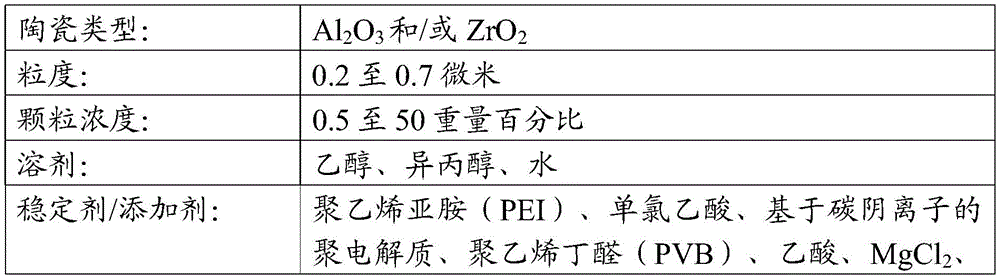

实施例2Example 2
Claims (15)
Applications Claiming Priority (3)
| Application Number | Priority Date | Filing Date | Title |
|---|---|---|---|
| EP20180927 | 2020-06-18 | ||
| EP20180927.4 | 2020-06-18 | ||
| PCT/EP2021/066517 WO2021255209A1 (en) | 2020-06-18 | 2021-06-17 | Heater assembly having fluid permeable heater with directly deposited transport material |
Publications (1)
| Publication Number | Publication Date |
|---|---|
| CN115697101A true CN115697101A (en) | 2023-02-03 |
Family
ID=71111241
Family Applications (1)
| Application Number | Title | Priority Date | Filing Date |
|---|---|---|---|
| CN202180042830.9A Pending CN115697101A (en) | 2020-06-18 | 2021-06-17 | Heater assembly having fluid permeable heater with directly deposited transfer material |
Country Status (10)
| Country | Link |
|---|---|
| US (1) | US20230329341A1 (en) |
| EP (1) | EP4167780B1 (en) |
| JP (1) | JP7799631B2 (en) |
| KR (1) | KR20230027148A (en) |
| CN (1) | CN115697101A (en) |
| BR (1) | BR112022023004A2 (en) |
| IL (1) | IL299037A (en) |
| PH (1) | PH12022553418A1 (en) |
| PL (1) | PL4167780T3 (en) |
| WO (1) | WO2021255209A1 (en) |
Families Citing this family (4)
| Publication number | Priority date | Publication date | Assignee | Title |
|---|---|---|---|---|
| US11502466B2 (en) * | 2018-10-12 | 2022-11-15 | Rai Strategic Holdings, Inc. | Aerosol delivery device with improved connectivity, airflow, and aerosol paths |
| US20240268485A1 (en) * | 2021-06-17 | 2024-08-15 | Philip Morris Products S.A. | Method and system for forming an aerosol-generating component of an aerosol-generating system |
| CN117044993A (en) * | 2022-05-06 | 2023-11-14 | 深圳麦克韦尔科技有限公司 | Porous biological ceramic modified heating structure and preparation method and application thereof |
| WO2023242091A1 (en) * | 2022-06-14 | 2023-12-21 | Philip Morris Products S.A. | Heater assembly for an aerosol-generating system and related manufacturing method |
Family Cites Families (9)
| Publication number | Priority date | Publication date | Assignee | Title |
|---|---|---|---|---|
| JP2014143129A (en) * | 2013-01-25 | 2014-08-07 | Stanley Electric Co Ltd | Method of manufacturing filament |
| UA118776C2 (en) * | 2014-02-10 | 2019-03-11 | Філіп Морріс Продактс С.А. | An aerosol-generating system having a fluid-permeable heater assembly |
| EP3821730B1 (en) * | 2015-07-09 | 2023-06-14 | Philip Morris Products S.A. | Heater assembly for an aerosol-generating system |
| US10485267B2 (en) * | 2016-07-25 | 2019-11-26 | Altria Client Services Llc | Fluid permeable heater assembly with cap |
| JP7483629B2 (en) * | 2018-05-31 | 2024-05-15 | フィリップ・モーリス・プロダクツ・ソシエテ・アノニム | HEATER ASSEMBLY HAVING TRANSPORTED MATERIAL THROUGH THEREOF |
| EP3855964B1 (en) * | 2018-09-28 | 2022-11-02 | Philip Morris Products S.A. | Heater assembly for an aerosol-generating system |
| CN110063523A (en) * | 2019-02-27 | 2019-07-30 | 广东达昊科技有限公司 | A kind of cigarette/electronic cigarette heating device |
| CN111053291B (en) * | 2019-12-02 | 2025-04-25 | 深圳麦克韦尔科技有限公司 | Electronic atomization device, atomization core and preparation method thereof |
| EP4098077A2 (en) * | 2020-01-28 | 2022-12-07 | Philip Morris Products S.A. | Heating element having heat conductive and wicking filaments |
-
2021
- 2021-06-17 EP EP21735219.4A patent/EP4167780B1/en active Active
- 2021-06-17 CN CN202180042830.9A patent/CN115697101A/en active Pending
- 2021-06-17 KR KR1020237000666A patent/KR20230027148A/en active Pending
- 2021-06-17 PH PH1/2022/553418A patent/PH12022553418A1/en unknown
- 2021-06-17 JP JP2022575772A patent/JP7799631B2/en active Active
- 2021-06-17 WO PCT/EP2021/066517 patent/WO2021255209A1/en not_active Ceased
- 2021-06-17 BR BR112022023004A patent/BR112022023004A2/en unknown
- 2021-06-17 PL PL21735219.4T patent/PL4167780T3/en unknown
- 2021-06-17 IL IL299037A patent/IL299037A/en unknown
- 2021-06-17 US US18/001,669 patent/US20230329341A1/en active Pending
Also Published As
| Publication number | Publication date |
|---|---|
| IL299037A (en) | 2023-02-01 |
| EP4167780B1 (en) | 2024-04-03 |
| WO2021255209A1 (en) | 2021-12-23 |
| EP4167780A1 (en) | 2023-04-26 |
| PH12022553418A1 (en) | 2024-04-22 |
| EP4167780C0 (en) | 2024-04-03 |
| KR20230027148A (en) | 2023-02-27 |
| US20230329341A1 (en) | 2023-10-19 |
| JP2023530247A (en) | 2023-07-14 |
| BR112022023004A2 (en) | 2022-12-20 |
| PL4167780T3 (en) | 2024-08-12 |
| JP7799631B2 (en) | 2026-01-15 |
Similar Documents
| Publication | Publication Date | Title |
|---|---|---|
| CN115697101A (en) | Heater assembly having fluid permeable heater with directly deposited transfer material | |
| CN110234241B (en) | For molded mounting of aerosol generating elements in aerosol generating systems | |
| CN110267556B (en) | Aerosol-generating system and cartridge for an aerosol-generating system having a two-part liquid storage compartment | |
| US20230082650A1 (en) | Heating element having heat conductive and wicking filaments | |
| CN116322394B (en) | Aerosol generating system with hybrid susceptor | |
| CN116528704A (en) | Inductively heated aerosol-generating system providing efficient and consistent heating of planar susceptor elements | |
| KR20220121857A (en) | Aerosol-generating devices that adapt to their surroundings | |
| JP7598337B2 (en) | Aerosol generating system and cartridge for an aerosol generating system having a particulate filter | |
| CN116326204A (en) | Heating element with increased resistance | |
| CN116528707A (en) | Aerosol generating system with shaped susceptors | |
| CN120390594A (en) | Heater assembly with measuring contacts | |
| RU2839646C1 (en) | Heater assembly for aerosol-generating system, cartridge for aerosol-generating system, aerosol-generating system, and method for making heater assembly for aerosol-generating system | |
| HK40091268B (en) | Heater assembly having fluid permeable heater with directly deposited transport material | |
| HK40091268A (en) | Heater assembly having fluid permeable heater with directly deposited transport material | |
| CN116491223A (en) | Heating element including conductive mesh | |
| RU2815886C2 (en) | Steam generating system and steam generating method | |
| US20240225107A1 (en) | Aerosol-generating device with overheating prevention | |
| KR20250170063A (en) | 2-part heater assembly | |
| KR20250169569A (en) | Ceramic heating element | |
| CN120417799A (en) | Heater assembly with sealed area | |
| KR20250169568A (en) | Heater assembly having a porous body | |
| KR20250158822A (en) | Aerosol generating device with improved aerosol extraction | |
| CN121001595A (en) | Heater assembly with curved surface |
Legal Events
| Date | Code | Title | Description |
|---|---|---|---|
| PB01 | Publication | ||
| PB01 | Publication | ||
| SE01 | Entry into force of request for substantive examination | ||
| SE01 | Entry into force of request for substantive examination |