CN115692272A - transfer device - Google Patents
transfer device Download PDFInfo
- Publication number
- CN115692272A CN115692272A CN202110826938.9A CN202110826938A CN115692272A CN 115692272 A CN115692272 A CN 115692272A CN 202110826938 A CN202110826938 A CN 202110826938A CN 115692272 A CN115692272 A CN 115692272A
- Authority
- CN
- China
- Prior art keywords
- pushing
- bearing
- sheet
- pressing
- piece
- Prior art date
- Legal status (The legal status is an assumption and is not a legal conclusion. Google has not performed a legal analysis and makes no representation as to the accuracy of the status listed.)
- Pending
Links
Images


Landscapes
- Labeling Devices (AREA)
Abstract
Description
技术领域technical field
本发明涉及半导体制造技术领域,特别地,涉及一种转移设备。The invention relates to the technical field of semiconductor manufacturing, in particular, to a transfer device.
背景技术Background technique
在半导体的制程中,会通过晶粒转移机构对切割完成的多个晶粒依其外观、质量或特性进行挑拣分类。目前,大多数的晶粒转移机构多采用通过一顶推装置中的顶推针将晶粒从一薄膜转移至印制电路板(PCB:Printed Circuit Board)上。但是,在转移过程中,由于用于承载晶粒的薄膜的面积较大且具有弹性,如果顶推装置直接顶推到薄膜进而来顶推晶粒的话,无法实现精准对位,容易出现翻晶或置下歪斜等情况,从而导致良率较低。In the manufacturing process of semiconductors, a plurality of cut dies are sorted by the die transfer mechanism according to their appearance, quality or characteristics. At present, most die transfer mechanisms use a push pin in a push device to transfer die from a film to a printed circuit board (PCB: Printed Circuit Board). However, during the transfer process, due to the large area and elasticity of the film used to carry the die, if the pushing device directly pushes the film and then pushes the die, precise alignment cannot be achieved, and crystal flipping is prone to occur Or set the skew, etc., resulting in a lower yield.
发明内容Contents of the invention
本发明是鉴于上述问题而完成的,提供一种能够实现精准对位,避免出现翻晶或置下歪斜等情况,且良率高的转移设备。The present invention is made in view of the above problems, and provides a transfer device capable of achieving precise alignment, avoiding crystal flipping or placing skew, and having a high yield rate.
为解决上述问题,本发明提供一种转移设备,其用于将第一承载片上的至少一个目标物转移至第二承载片,所述转移设备包括:移动放置装置,其用于将所述第一承载片放置于第一承载区域和将所述第二承载片放置于第二承载区域,使得所述第一承载片和所述第二承载片相向间隔且可相对平移;按压件,其可移动地设置于所述第一承载区域的背离所述第二承载区域的一侧,所述按压件用于沿预设移动方向按压所述第一承载片,使得所述第一承载片的待顶推的所述目标物的设置区域靠近所述第二承载片,所述预设移动方向为所述第一承载区域朝向所述第二承载区域的方向;以及顶推装置,其可移动地设置于所述第一承载区域的背离所述第二承载区域的一侧,所述顶推装置包括顶推件,所述顶推件的前端用于沿所述预设移动方向穿过所述按压件以顶推所述目标物,其中,所述按压件包括侧壁,所述侧壁远离所述第一承载区域的一侧开设有第一缺口,所述第一缺口用于供所述顶推装置穿过。In order to solve the above problems, the present invention provides a transfer device, which is used to transfer at least one target object on the first carrier sheet to the second carrier sheet, the transfer device includes: a mobile placement device, which is used to transfer the first object to the second carrier sheet A carrying sheet is placed on the first carrying area and the second carrying sheet is placed on the second carrying area, so that the first carrying sheet and the second carrying sheet are spaced apart from each other and can be relatively translated; the pressing member can is movably arranged on a side of the first carrying area away from the second carrying area, and the pressing member is used to press the first carrying sheet along a preset moving direction, so that the to-be-held position of the first carrying sheet The setting area of the pushing target is close to the second carrying sheet, and the preset moving direction is the direction of the first carrying area toward the second carrying area; and a pushing device, which is movably It is arranged on a side of the first loading area away from the second loading area, the pushing device includes a pushing piece, and the front end of the pushing piece is used to pass through the The pressing part is used to push the target object, wherein the pressing part includes a side wall, and a first notch is opened on a side of the side wall away from the first bearing area, and the first notch is used for the The jacking device passes through.
在一实施方式中,所述按压件形成一第二缺口,所述第二缺口设置于所述按压件靠近所述第一承载区域的一侧。In one embodiment, the pressing member forms a second notch, and the second notch is disposed on a side of the pressing member close to the first bearing area.
在一实施方式中,所述按压件进一步包括按压环和安装部,所述按压环限定了所述第二缺口,所述安装部且与所述按压环相对设置,所述安装部和所述按压环分别设置于所述侧壁的两侧。In one embodiment, the pressing member further includes a pressing ring and a mounting portion, the pressing ring defines the second notch, the mounting portion is arranged opposite to the pressing ring, the mounting portion and the The pressing rings are respectively arranged on both sides of the side wall.
在一实施方式中,所述按压环的底表面与侧表面的连接处形成倒圆角。In one embodiment, the connection between the bottom surface and the side surface of the pressing ring is rounded.
在一实施方式中,所述第二缺口为圆孔。In one embodiment, the second notch is a circular hole.
在一实施方式中,所述侧壁上还形成一穿孔,所述穿孔与所述第一缺口相对设置。In one embodiment, a perforation is further formed on the side wall, and the perforation is disposed opposite to the first notch.
所述转移设备还包括影像撷取装置,其固定地设置于所述第一承载区域的背离所述第二承载片的一侧,用于对要顶推的所述目标物进行取像。The transfer device further includes an image capturing device, which is fixedly disposed on a side of the first carrying area away from the second carrying sheet, and is used for capturing an image of the object to be pushed.
在一实施方式中,在所述顶推装置顶推所述目标物时,所述顶推装置、所述按压件以及所述影像撷取装置彼此间的相对位置为同轴。In one embodiment, when the pushing device pushes the target, the relative positions of the pushing device, the pressing member and the image capturing device are coaxial.
在一实施方式中,所述顶推装置包括顶针盖,所述顶推件可凸伸出所述顶针盖。In one embodiment, the pushing device includes a thimble cover, and the pushing piece can protrude out of the thimble cover.
在一实施方式中,所述移动放置装置包括第一放置部及第二放置部,所述第一放置部及所述第二放置部以相向间隔且可相对平移的方式设置。In one embodiment, the mobile placement device includes a first placement part and a second placement part, and the first placement part and the second placement part are arranged in a manner of being spaced apart from each other and capable of relative translation.
相较于现有技术,通过设置按压件按压第一承载片,使得在顶推目标物时,第一承载片的要顶推的目标物的设置区域向第二承载片靠近,容易对要顶推的目标物的设置区域的张力进行控制,且调整第一承载片的要顶推的目标物的设置区域与第二承载片之间的距离,从而使得顶推装置能够精准地顶推目标物,避免出现翻晶或置下歪斜等情况,且良率高。Compared with the prior art, by arranging the pressing member to press the first carrier sheet, when pushing the target object, the setting area of the target object to be pushed on the first carrier sheet approaches the second carrier sheet, and it is easy to push the object to be pushed. Control the tension of the setting area of the target to be pushed, and adjust the distance between the setting area of the target to be pushed on the first carrier sheet and the second carrier sheet, so that the pushing device can accurately push the target , to avoid situations such as flipping the crystal or placing it skewed, and the yield rate is high.
附图说明Description of drawings
为了更清楚地说明本申请实施方式或现有技术中的技术方案,下面将对实施方式或现有技术描述中所需要使用的附图作简单地介绍,显而易见地,下面描述中的附图仅仅是本申请的一些实施方式,对于本领域普通技术人员来讲,在不付出创造性劳动的前提下,还可以根据这些附图获得其它的附图。In order to more clearly illustrate the technical solutions in the embodiments of the present application or the prior art, the following will briefly introduce the drawings that need to be used in the description of the embodiments or the prior art. Obviously, the drawings in the following description are only These are some implementations of the present application. Those skilled in the art can also obtain other drawings based on these drawings without any creative effort.
图1是本发明一实施方式的转移设备的立体结构图。FIG. 1 is a three-dimensional structure diagram of a transfer device according to an embodiment of the present invention.
图2是图1所示的转移设备的主视图。Fig. 2 is a front view of the transfer device shown in Fig. 1 .
图3是图2所示的转移设备的局部放大图。Fig. 3 is a partially enlarged view of the transfer device shown in Fig. 2 .
图4是图3所示的转移设备的局部放大图。FIG. 4 is a partially enlarged view of the transfer device shown in FIG. 3 .
图5是图1的转移设备中的按压件的俯视图。FIG. 5 is a top view of a pressing member in the transfer device of FIG. 1 .
图6是图5所示的按压件的立体结构图。FIG. 6 is a three-dimensional structural view of the pressing member shown in FIG. 5 .
图7是图5所示的按压件的主视图。Fig. 7 is a front view of the pressing piece shown in Fig. 5 .
图8是图5所示的按压件的侧视图。Fig. 8 is a side view of the pressing piece shown in Fig. 5 .
图9的(a)~(d)是移动并转移晶粒的动作流程示意图。(a) to (d) of FIG. 9 are schematic diagrams of the operation flow of moving and transferring the crystal grains.
图10是转移设备转移目标物的流程示意图。Fig. 10 is a schematic flow chart of transferring objects by the transfer device.
图11是转移设备转移目标物的流程示意图。Fig. 11 is a schematic flow chart of transferring objects by the transfer device.
图12是转移设备转移目标物的流程示意图。Fig. 12 is a schematic flow chart of transferring objects by the transfer device.
图13是转移设备转移目标物的流程示意图。Fig. 13 is a schematic flow chart of transferring objects by the transfer device.
图14是转移设备转移目标物的流程示意图。Fig. 14 is a schematic flow chart of transferring objects by the transfer device.
图15是转移设备转移目标物的流程示意图。Fig. 15 is a schematic flow chart of transferring objects by a transfer device.
图16是转移设备转移目标物的流程示意图。Fig. 16 is a schematic flow chart of transferring objects by the transfer device.
具体实施方式Detailed ways
以下叙述含有与本发明中的示例性实施例相关的特定信息。本发明中的附图和其随附的详细叙述仅为示例性实施例。然而,本发明并不局限于此些示例性实施例。本领域技术人员将会想到本发明的其它变化与实施例。除非另有说明,否则附图中的相同或对应的组件可由相同或对应的附图标号指示。此外,本发明中的附图与例示通常不是按比例绘制的,且非旨在与实际的相对尺寸相对应。The following description contains specific information related to exemplary embodiments of the present invention. The drawings in this disclosure and their accompanying detailed description are exemplary embodiments only. However, the invention is not limited to such exemplary embodiments. Other variations and embodiments of the invention will occur to those skilled in the art. Unless otherwise stated, identical or corresponding components in the figures may be indicated by identical or corresponding reference numerals. Furthermore, the drawings and illustrations in this disclosure are generally not drawn to scale and are not intended to correspond to actual relative dimensions.
出于一致性和易于理解的目的,在示例性附图中藉由标号以标示相同特征(虽在一些示例中并未如此标示)。然而,不同实施方式中的特征在其它方面可能不同,因此不应狭义地局限于附图所示的特征。For purposes of consistency and ease of understanding, like features (although in some instances they are not) are labeled by reference numerals in the exemplary figures. However, features in different implementations may differ in other respects and therefore should not be narrowly limited to those shown in the drawings.
本发明的说明书及上述附图中的术语“第一”、“第二”和“第三”等是用于区别不同对象,而非用于描述特定顺序。此外,术语“包括”以及它们任何变形,意图在于覆盖不排他的包含。The terms "first", "second" and "third" in the description of the present invention and the above drawings are used to distinguish different objects, rather than to describe a specific order. Furthermore, the term "comprise", as well as any variations thereof, are intended to cover non-exclusive inclusion.
下面,结合附图及实施例对本发明进行详细说明。Below, the present invention will be described in detail with reference to the drawings and embodiments.
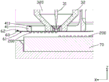
参照图1~图4,本发明一实施方式提供一种转移设备100,包括基座10、移动放置装置20、顶推装置30、按压件40及影像撷取装置50,其中,移动放置装置20、顶推装置30、按压件40及影像撷取装置50均设置于基座10上。Referring to FIGS. 1 to 4 , an embodiment of the present invention provides a
本实施方式中的转移设备100用于转移至少一目标物200,在本实施方式中,目标物200以晶粒为例进行说明,在其它实施方式中,转移设备100还可以用于转移其它目标物,在此不作限定。具体地,转移设备100用于将第一承载片60及第二承载片70设置于移动放置装置20,并通过顶推装置30、按压件40及影像撷取装置50将第一承载片60上的目标物200转移至第二承载片70上。The
在本实施方式中,第一承载面60的面向第二承载片70的表面用于放置至少一目标物200,具体地,第一承载片60具有承载目标物200的承载面61及与承载面61相背的接触面62,承载面61面向第二承载片70。第二承载片70具有供目标物200设置的设置面71,设置面71面向第一承载片60。In this embodiment, the surface of the first carrying
可以理解,在顶推件31顶推目标物200且并未刺破第一承载片60的情况下,第一承载片60的粘度可能会因第一承载片60表面被拉伸而降低,此时,承载面61的粘度低于设置面71的粘度的情况下,目标物200较容易脱离第一承载片60,而粘至于第二承载片70。当然,在其它时期,例如,后述的按压件30未按压第一承载片60时,承载面61的粘度也可以不低于设置面71的粘度,在此不作限定。It can be understood that, when the pushing
本实施方式中,第二承载片70可以为印制电路板(PCB),且在可以在印制电路板上形成一层粘接层,例如胶水。在本实施方式中,目标物200即晶粒以发光二极体晶粒为例,第一承载片60以及第二承载片70以蓝膜(blue tape)为例进行说明。在本实施方式中,第一承载片60是通过扩张环(expand ring)63进行固定,扩张环63包括内环631及外环632,第一承载片60的周缘通过内环631及外环632固定。In this embodiment, the
可以理解,通过扩张环63拉伸第一承载片60的周缘,使得第一承载片60扩张而降低其粘度,以便于后续转移目标物200。It can be understood that the peripheral edge of the
当然,在其它实施方式中,第一承载片60还可以通过其它结构进行固定拉伸,在此不作限定。Certainly, in other implementation manners, the
移动放置装置20包括相向间隔且可相对平移的第一放置部21及第二放置部22,第一放置部21及第二放置部22分别用于放置第一承载片60和第二承载片70,使得第一承载片60和第二承载片70相向间隔且可相对平移,第一承载片60上的目标物200位于第一承载片60和第二承载片70之间。The
请结合参阅图1-图3,在本实施方式中,第一放置部21有第一承载区域23,用于放置第一承载片60,第二放置部22有第二承载区域24,用于放置第二承载片70。在本实施方式中,第一承载区域23为在第一承载片60放置于第一放置部21的情况下,与第一承载片60所在的平面一致的区域,第二承载区域24为在第二承载片70放置于第二放置部22的情况下,与第二承载片所在的平面一致的区域。换言之,第一承载区域23和第二承载区域24各自被定义为虚拟的平面区域,分别用于反映第一承载片60和第二承载片70放置于移动放置装置20时的位置。故可以理解的是,当移动放置装置20改变第一承载片60和/或第二承载片70的位置,第一承载区域23和第二承载区域24的位置也会相应的改变。Please refer to FIGS. 1-3 in combination. In this embodiment, the first placing
进一步地,第一放置部21设置于基座10的一侧,第一放置部21包括第一基台211及承载盘212,第一基台211可相对于基座10在第一方向X上移动地设置,承载盘212可在第二方向Y上移动地设置于第一基台211上,如此,使得扩张环63上的目标物200能够沿第一方向X和第二方向Y往返移动,从而便于放置、拿取、平移扩张环63。Further, the
第二放置部22设置于基座10的另一侧,第二放置部22包括第二基台221及夹持件222,第二基台221可相对于基座10在第一方向X上移动地设置,夹持件222用于夹持第二承载片70,夹持件222可在第二方向Y上移动地设置于第二基台221上,如此,第二承载片70能够沿第一方向X和第二方向Y往返移动,从而便于放置、拿取、平移第二承载片70。The
顶推装置30可移动地设置于第一承载区域23的背离第二承载片70的一侧。在本实施方式中,顶推装置30在水平面和/或垂直面能够移动。具体地,在顶推目标物200之前,顶推装置30位于顶推准备位置,在要对待顶推的目标物200进行顶推时,顶推装置30从顶推准备位置移动至顶推工作位置,待顶推动作结束之后,顶推装置30从顶推工作位置返回至顶推准备位置,如此,进行往返移动。在本实施方式中,目标物200是指承载于第一承载片60上的晶粒,待顶推的目标物200是指第一承载片60上的晶粒中,在顶推装置30位于顶推工作位置时,位于顶推件31正下方的晶粒,顶推准备位置是指顶推装置30的默认的初始位置,顶推工作位置是指顶推装置30顶推目标物200时所处的位置。The pushing
具体地,顶推装置30包括顶推件31及顶针盖32,顶推件31可凸伸出顶针盖32的腔体320内,以顶推目标物200,从而将第一承载片60上的目标物200转移至第二承载片70。在本实施方式中,顶推件31可为顶针(Needle)。Specifically, the pushing
具体而言,当顶推件31要顶推目标物200时,顶针盖32的腔体320内成为真空状态,如此,顶针盖32的底部将吸附第一承载片60,使得顶针盖32的底部与第一承载片60的接触面62接触,之后顶推件31伸出顶针盖32并顶推目标物200,以将目标物200从第一承载片60转移至第二承载片70,之后,顶推件31返回至顶针盖32内。可以理解,通过将顶推件31可凸伸出地设置于顶针盖32内,当顶推件31顶推目标物200之后,顶针盖32的底部与第一承载片60的接触面62接触,从而能够防止第一承载片60粘附于顶推件31的前端而发生偏移,如此,能够有效地提高顶推效率。Specifically, when the
进一步地,请结合参阅图5,按压件40可移动地设置于第一承载区域23的背离第二承载区域24的一侧,用于按压第一承载片60,使得第一承载片60上的待顶推的目标物200的设置区域靠近第二承载片70。Further, please refer to FIG. 5 , the pressing
可以理解,在本实施方式中,按压件40能够在垂直面移动。It can be understood that, in this embodiment, the pressing
具体地,在顶推目标物200之前,按压件40位于按压准备位置,在要对目标物200进行顶推时,按压件40从按压准备位置移动至按压工作位置,直至第一承载片60的所有目标物200都转移至第二承载片70之后,按压件40从按压工作位置返回至按压准备位置。当然,也可以在每顶推完一个(或数个)目标物200之后,按压件40从按压工作位置返回至按压准备位置,对此不作限定。按压准备位置是指按压件40的默认的初始位置,按压工作位置是指按压件40按压第一承载片60时所处的位置。Specifically, before pushing the
当然,在其它实施方式中,按压件40也能够在水平面及垂直面移动,在此不作限定。Of course, in other embodiments, the pressing
可以理解,在本实施方式中,只要确保第一承载片60中的与按压件40接触的区域即对应于顶推装置30顶推目标物200的区域在按压件40的按压作用下向第二承载片70靠近即可,在此不作限定。It can be understood that, in this embodiment, it is only necessary to ensure that the area of the
具体地,请结合参阅图5~图8,按压件40形成一第二缺口411,第二缺口411设置于按压件40靠近第一承载区域23的一侧,用于供顶推装置30的顶推件31的前端沿预设移动方向穿过以顶推至少一个目标物200。在本实施方式中,第二缺口411用于供顶针盖32的底部和顶推件31穿过。在本实施方式中,预设移动方向为后述的第三方向Z,也可以说是第一承载区域23朝向第二承载区域24的方向。当然,在其它实施方式中,可以根据需求进行相应的调整,在此不作限定。Specifically, referring to FIGS. 5 to 8 , the pressing
进一步地,第二缺口411可为封闭式缺口,例如呈“O”字状、“口”字状等。在其它实施方式中,第二缺口411也可以为开放式的缺口,例如呈“C”、“ㄈ”字状等。在本实施方式中,该第二缺口411为圆孔,即呈“O”字状。在一些实施方式中,该第二缺口411虽大致呈圆孔或其他封闭式缺口,但该第二缺口411的边缘可包含一或多个切口。进一步说,以该第二缺口411的边缘具有一个切口的情况为例,该第二缺口411会呈“C”字状,以此类推。当然,在其它实施方式中,该第二缺口411还可为其它的形状,在此不作限定。Further, the
进一步地,按压件40包括按压环41、侧壁42及安装部43,按压环41限定第二缺口411。Further, the pressing
可以理解,第二缺口411的直径没有特别限制,只要能够允许顶推装置30的至少部分穿过,在本实施方式中,第二缺口411允许顶推装置30的顶针盖32的底部穿过,不会妨碍到顶推件31顶推目标物200即可。更具体地,第二缺口411的直径为6mm以上,在一优选实施方式中,第二缺口411的直径为16mm。另外,在一具体实施方式中,按压环41的内径D1为13.5mm,外径D2为16.0mm。在一些实施方式中,内径的范围约8mm~20mm,按压环41的环宽度D3的范围约1~2mm。It can be understood that the diameter of the
可以理解,通过将第二缺口411的直径设置为允许顶针盖32的底部穿过,能够降低扩张环63在水平移动时,第一承载片60与按压环41之间的摩擦力,并使第一承载片60中的与按压件40接触的区域的张力更加稳定。当然,按压环41的直径可以根据需求进行相应地调整,在此不作限定。It can be understood that by setting the diameter of the
进一步地,按压环41的底表面412与侧表面413的连接处形成倒圆角(R角),R角的圆弧角例如为0.5mm,以防止按压环41的底表面412与第一承载片60接触,且第一承载片60水平移动时把第一承载片60刮破。在其他实施方式中,若第一承载片60可承受按压环41在其上移动摩擦而不被刮破,亦可允许将按压环41的底表面412与侧表面413的连接处形成为其他形状,例如钝角。Further, the connection between the
在本实施方式中,侧壁42设置于按压环41上,侧壁42为镂空结构。具体的,侧壁42的远离第一承载区域23的一侧开设有第一缺口420,第一缺口420供顶推装置30穿过。具体地,供顶推装置30穿过,以从顶推准备位置到顶推工作位置之间往返移动。In this embodiment, the
可以理解,第一缺口420的大小不作限定,只要不会妨碍顶推装置30穿过该第一缺口420而往返于顶推准备位置和顶推工作位置即可。在本实施方式中,第一缺口420贯穿侧壁42的两侧,即第一缺口420从侧壁42的远离按压环41的一侧延伸至按压环41。It can be understood that the size of the
在本实施方式中,预设移动方向为纵向(或是顶推件31的长度方向),当然,在其它实施方式中,可以根据需求进行调整,在此不作限定。In this embodiment, the preset moving direction is the longitudinal direction (or the length direction of the pusher 31 ), of course, in other embodiments, it can be adjusted according to requirements, which is not limited here.
进一步地,侧壁42上还开设有穿孔422。穿孔422与第一缺口420相对设置。Further, the
在本实施方式中,安装部43大致呈“C”字状,安装部43与按压环41相对设置,分别设置于侧壁42的两侧。In this embodiment, the mounting
进一步地,安装部43上开设有多个安装孔430,以通过固定机构(未图示)安装于基座10上。在本实施方式中,安装部43的厚度随着远离侧壁42增加,以便于在安装部43上开设安装孔430,从而安装于基座10上。Further, a plurality of mounting
可以理解,通过将安装部43设置为C字状,如此,按压件40一侧设置有侧壁42,而另一侧未设置形成第一缺口420,用于供顶推装置30穿过而移动到顶推工作位置,即顶推目标物200的位置的正上方。此外,第一缺口420与侧壁42中的穿孔422相对设置,有便于两侧的光源(未图示)分别通过第一缺口420及穿孔422,从而有助于在取像时打光。It can be understood that by setting the
进一步地,在按压件40按压第一承载片60之前,第一承载片60与第二承载片70之间的距离为一预定值,例如1.5mm。按压件40可沿着第三方向Z移动并按压第一承载片60,以进一步微调第一承载片60与第二承载片70之间的距离。举例来说,在按压件40按压第一承载片60时,按压件40可沿第三方向Z下压,使第一承载片60的要顶推的目标物200的设置区域和第二承载片70之间的距离缩短至特定值,例如0.5mm或以下,例如0.2mm、0.4mm等。Further, before the pressing
当然,在其它实施方式中,按压件40还能够采用其它的结构,只要能够按压到第一承载片60,使得第一承载片60的要顶推的目标物200的设置区域向第二承载片70靠近即可,其具体结构不受限制。Of course, in other embodiments, the pressing
影像撷取装置50通过固定组件51固定地设置于基座10上,并位于第一承载区域23的背离第二承载区域24的一侧,用于对要顶推的目标物200进行取像。对于固定组件51,可以采用公知的固定结构,在此不再赘述。The
影像撷取装置50的设置并无特别限制,只要对应目标物200设置而能对目标物200进行取像便可。在本实施方式中,影像撷取装置50可为摄影机(CCD),但不限定于此。The setting of the
在顶推目标物200时,影像撷取装置50与顶推装置30彼此间的相对位置为同轴,且在顶推装置30顶推目标物200之前,可通过影像撷取装置50拍照、取像进而精准地计算目标物200的位置,从而将要顶推的目标物200移动至顶推装置30的正中心,即要顶推的目标物200与顶推装置30、按压件40以及影像撷取装置50彼此间的相对位置为同轴,确保每颗要顶推的目标物200的位置精度及顶推装置30内的顶推件31能顶推到目标物200的正中心,因目标物200为晶粒,体积较小,约为0.08~0.15mm的长方体,若顶推件31偏移0.01mm以上则容易导致在顶推过程中出现翻晶或置下歪斜等情况。When pushing the
优选地,在本实施方式中,影像撷取装置50通过直接、正视取像来对目标物200进行取像。Preferably, in this embodiment, the
在本实施方式中,顶推装置30、按压件40及影像撷取装置50同一侧,当然,在其它实施方式中,顶推装置30、按压件40及影像撷取装置50也可以位于不同侧,只要将顶推装置30及按压件40设置为位于同一侧即可。例如,顶推装置30及按压件40位于与影像撷取装置50不同的一侧,此时,影像撷取装置50位于第二承载区域24的背离第一承载片60的一侧,而顶推装置30及按压件40位于第一承载片60的背离第二承载区域24的一侧。In this embodiment, the pushing
可以理解,顶推装置30位于顶推准备位置时,顶推装置30不会对影像撷取装置50撷取按压件40内的目标物200的影像造成影响。顶推装置30在顶推准备位置与顶推工作位置之间移动的目的在于:影像撷取装置50能够轻易地撷取目标物200的影像,不需要通过额外的光学反射。It can be understood that when the pushing
请结合参阅图9的(a)~(d),对转移设备100移动并转移晶粒的动作流程作进一步说明。Please refer to (a)-(d) of FIG. 9 to further describe the operation flow of the
请参阅图9的(a),影像撷取装置50进行取像,并计算晶粒1与顶推位置O之间的位置偏差d1、以及晶粒1与晶粒2之间的位置偏差d2。可以理解,顶推位置O是始终保持不变的,位置偏差d1为晶粒1的中心与顶推位置O之间的距离,位置偏差d2为晶粒1的中心与晶粒2的中心之间的距离。位置偏差d2又可称为晶粒间距(pitch)。Please refer to (a) of FIG. 9 , the
接着,请参阅图9的(b),根据d1,晶粒1被移至顶推位置O。可以理解,将晶粒1移至顶推位置O,是指通过移动第一承载片60,使得晶粒1与顶推位置O重叠,下述将晶粒2移至顶推位置O也是同样的。Next, referring to (b) of FIG. 9 , the
接着,从顶推准备位置移至顶推工作位置的顶推装置30顶推晶粒1,以将晶粒1从第一承载片60转移到第二承载片70上。Next, the pushing
请参阅图9的(c),将晶粒1顶推至第二承载片70后,移动放置装置20根据d2移动第一承载片60,以将晶粒2移至顶推位置O。不过,由于顶推装置30在顶推晶粒1之后,无论顶推时是否有戳破第一承载片60,皆可能使第一承载片60的张力或其他特性产生变化,使得第一承载片60上的其他晶粒(例如晶粒2、晶粒3)的位置发生改变。因此,仅根据d2来移动晶粒2的话很可能无法将晶粒2精准地移至顶推位置O。如图9的(c)所示,单凭d2来移动晶粒2,并无法使晶粒2精准地对齐顶推位置O。Referring to (c) of FIG. 9 , after pushing the
接着,类似于图9中的(a)的动作,影像撷取装置50对晶粒2进行取像,并计算晶粒2与顶推位置O之间的位置偏差、以及晶粒2与下一颗待顶推的晶粒(例如,晶粒3)之间的位置偏差(即pitch)。应注意的是,顶推装置30在完成顶推晶粒1之后,会从顶推工作位置返回顶推准备位置,以避免阻碍影像撷取装置50对晶粒2进行取像。Next, similar to the action of (a) in FIG. 9 , the
之后,请参阅图9的(d),类似于图9中的(b)的动作,移动放置装置20根据前述计算出的晶粒2与顶推位置O之间的位置偏差,移动第一承载片60以对晶粒2的位置进行微调,使得晶粒2精准地位于顶推位置O。顶推装置30则会再次由顶推准备位置进入顶推工作位置,以对晶粒2进行顶推。Afterwards, please refer to (d) of FIG. 9 , similar to the action of (b) in FIG. 9 , the moving
上述图9的(a)~(d)的动作大致包括影像撷取装置50对晶粒进行取像的「取像阶段」、根据取像结果将晶粒精准移到顶推位置O的「中心(center)定位阶段」、将晶粒顶推至第二承载片70的「顶推阶段」、以及根据取像阶段得到的pitch来移动下一颗晶粒的「pitch定位阶段」。在一些实施方式中,上述四个阶段可依序并反复地执行,以逐一将第一承载片60上的晶粒转移至第二承载片70上。The actions of (a) to (d) in FIG. 9 above generally include the "image capture stage" in which the
转移设备100还包括第一驱动装置80,第一驱动装置80用于控制按压件40在垂直面移动。更具体地,第一驱动装置80用于控制按压件40在第三方向Z(即预设移动方向)上移动。The
进一步地,按压件40也可以在第一驱动装置80的控制作用下在水平面和垂直面移动。可以理解,按压件40能够在水平面移动,以对该按压件40进行维修或者更换。换言之,除了沿垂直面(即包含第一移动方向的平面)移动,亦允许按压件40在水平面上移动(例如从维护位置移动至按压准备位置,或从按压准备位置返回维护位置),以方便人员对该按压件40进行维修或者更换。Further, the pressing
更具体地,在扩张环63载置于承载盘212后,要对第一承载片60上的目标物200进行顶推时,按压件40在第一驱动装置80的控制下,移动至第一承载片60上并按压第一承载片60,使得第一承载片60的要顶推的目标物200的设置区域向第二承载片70靠近,且持续保持按压第一承载片60,直至第一承载片60上的目标物200全部转移至第二承载片70上,在第一驱动装置80的控制下,移动至按压准备位置。待作业人员更换下一扩张环63后,重复上述动作。More specifically, after the
转移设备100还包括第二驱动装置90,其用于控制顶推装置30沿特定轨迹移动。所述特定轨迹可对应所述顶推装置30在第一方向X、第二方向Y、及/或第三方向上的位置改变。举例来说,所述特定轨迹可大致呈弧线状。然而本揭露并不限于此,所述特定轨迹亦可呈直线或其他形状,只需所述特定轨迹可供顶推装置30往返移动于不同特定位置(例如,顶推准备位置、顶推工作位置等)即可。The
可以理解,在影像撷取装置50对要顶推的目标物200取像之后,第二驱动装置90控制顶推装置30从顶推准备位置移动至顶推工作位置,顶推件31穿过按压件40顶推目标物200之后,顶推装置30从顶推工作位置返回至顶推准备位置,待影像撷取装置50对下一颗要顶推的目标物200取像之后,第二驱动装置90再次控制顶推装置30从顶推准备位置移动至顶推工作位置,如此进行反复,从而将第一承载片60上的目标物200转移至第二承载片70上。It can be understood that after the
用于放置目标物200的第一承载片60的面积较大,顶推件31直接顶推第一承载片60上的目标物200时张力不易受控制,容易波及整个第一承载片60。而在本实施方式中,在顶推目标物200时,按压件40移动至与第一承载片60的接触面62接触并按压第一承载片60,使得第一承载片60的要顶推的目标物200的设置区域向第二承载片70靠近,这样,张力的变化不易波及整个第一承载片60,从而容易对要顶推的目标物200的设置区域的张力进行控制。The
进一步地,由于材料、加工等原因,第一承载片60与第二承载片70之间的间距较大,通常,第一承载片60与第二承载片70之间的间距达到1.5mm以上,而优选的作业距离,即优选的方案中,第一承载片60与第二承载片70之间的间距需要在0.5mm以下。在本实施方式中,通过设置按压件40按压第一承载片60,使得第一承载片60的要顶推的目标物200的设置区域向第二承载片70靠近,使得第一承载片60的要顶推的目标物200的设置区域与第二承载片70之间的间距处于预设范围内,例如0.5mm以下,以便于顶推件31顶推目标物200。如此,通过设置按压件40,能够对第一承载片60与第二承载片70之间的距离进行有效地控制。当然,第一承载片60的要顶推的目标物200的设置区域与第二承载片70之间的间距可以根据需求进行相应的调整,在此不作限定。Further, due to material, processing and other reasons, the distance between the
在本实施方式中,由于扩张环63通常是由人工摆放并且通过固定结构进行固定,此外,扩张环63中的内环631和外环632在结合时也可能会存在公差,若通过扩张环63自身来实现高度控制,以对第一承载片60与第二承载片70之间的距离进行微调,则需要更高的成本。In this embodiment, since the
这是因为除了整个扩张环63的面积较大而难以控制外,难以确保人工摆放扩张环63的位置均一致,即每个阶段的扩张环63的摆放位置存在差异,难以将第一承载片60的高度调整到一致,如此,便难以确保第一承载片60与第二承载片70之间的距离。而在本实施方式中,通过按压件40对第一承载片60进行按压,由于按压件40的按压工作位置是固定的,如此,即使每个阶段的扩张环63的摆放位置存在差异,通过按压件40按压,能够将第一承载片60的要顶推的目标物200的设置区域与第二承载片70之间的距离一致,即能够容易地实现高度控制。This is because except that the area of the
例如,在不设置按压件40的情况下,假设第一承载片60在初始人工摆放时未与第二承载片70完全平行,比如,第一承载片60左侧高于右侧,如此,在转移第一承载片60的左侧的目标物200时,位于左侧的第一承载片60与第二承载片70之间的距离较大,反之转移右侧目标物200时,位于右侧的第一承载片60到第二承载片70之间的距离较小,如此,即使顶推装置30在同一位置顶推目标物200,即顶推路径相同,也会导致顶推的结果不同,也就是说,这两种情况下实际上顶推目标物200后目标物200向第二承载片70移动的距离不同。而通过设置按压件40对第一承载片60进行按压,即使出现上述情况,也能确保在顶推左侧和右侧的目标物200时,目标物200向第二承载片70移动的距离均相同。For example, in the absence of the pressing
而且,工业用的CCD由于需要高速取像,因此,通常不具有自动对焦的功能,通过设置按压环41按压第一承载片60,使得第一承载片60的要顶推的目标物200的设置区域保持在固定位置,能够维持固定的焦距,使得CCD能够快速取像且成像清晰。Moreover, industrial CCDs do not usually have an autofocus function due to the need for high-speed imaging. By setting the
此外,在顶推目标物200之后,顶推装置30移动至顶推准备位置,以让影像撷取装置50取像从而对下一颗要顶推的目标物200进行定位,因第一承载片60为有弹性的膜,随着时间、目标物200的数量不同,容易导致第一承载片60发生位置偏差,而在本实施方式中,通过设置按压件40按压第一承载片60,能够有效地使第一承载片60在水平面平稳地移动,从而避免出现上述情况。In addition, after pushing the
以下,结合图10~图16对本实施方式的转移设备100的转移目标物200的方法进行说明。Hereinafter, a method of transferring the
当使用如图1所示的转移设备100进行目标物200挑拣制程时,本发明转移目标物200的方法的一实施例包含以下步骤,需要说明的是,对于目标物的准备及放置可以通过公知的技术进行,因此,在此不再赘述。When using the
首先,请结合参阅图10,将设置有目标物200的第一承载片60与第二承载片70分别设置于第一放置部21及第二放置部22上,并让目标物200位于第一承载片60与第二承载片70之间。此时,顶推装置30位于顶推准备位置,按压件40位于维护位置。在本实施方式中,顶推装置30与按压件40位于轴线A的两侧。换言之,顶推准备位置和维护位置位于轴线A的两侧。在一些实施例中,顶推准备位置和维护位置可以是不在轴线A上的其他位置。First, please refer to FIG. 10 , the
接着,请结合参阅图11,平移第一放置部21及第二放置部22,使第一承载片60上的目标物200对应移动至影像撷取装置50的轴线A上,并通过影像撷取装置50检测目标物200,此时,顶推装置30位于顶推准备位置,按压件40位于按压准备位置,即按压件40与影像撷取装置50同轴。Next, please refer to FIG. 11 , translate the
接着,请结合参阅图12,将按压件40移动至第一承载片60上,并按压第一承载片60,使得第一承载片60的要顶推的目标物200的设置区域向第二承载片70靠近。此时,顶推装置30位于顶推准备位置。Next, please refer to FIG. 12 , move the pressing
接着,请结合参阅图13~图14,将顶推装置30从顶推准备位置移动至顶推工作位置,即让顶推件31穿过按压环41顶推第一承载片60,并顶起对应的目标物200而直接将被顶推的目标物200转移粘置于第二承载片70上,以完成目标物200挑拣制程。Next, please refer to Figures 13 to 14, move the pushing
接着,请参阅图15,将顶推件31归位,使得顶推件31缩回至顶针盖32内,此时,顶推装置30位于顶推工作位置,按压件40按压第一承载片60。Next, please refer to FIG. 15 , return the
接着,请结合参阅图16,顶推装置30返回至顶推准备位置,按压件40按压第一承载片60,平移第一承载片60及第二承载片70,以便于进入顶推下一颗目标物200的流程。Next, please refer to FIG. 16 , the pushing
此处要特别说明的是,通过前置处理步骤的初始承载片的辅助,将各目标物200的发光面覆盖设置于第一承载片60的承载面时,使目标物200由第一承载片60转移到第二承载片70时,让目标物200的发光面能反向第二承载片70的设置面裸露。此外,由于是先通过将目标物200的发光面反置于第一承载片60上,使得目标物200在第一承载片60的位置相对于位在初始承载片上的位置也是对应反置,因此,在进行目标物200的转移前,会根据已被翻转设置的目标物200的位置,对应调整控制软体进行位置翻转处理。It should be particularly noted here that, with the assistance of the initial carrier sheet in the pre-processing step, when the light-emitting surface of each
本发明不限于上述的各实施方式,能够在权利要求所示的范围内进行各种变更,对于适当组合在不同的实施方式中分别公开的技术手段而得到的实施方式也包含在本发明的技术范围内。进一步地,通过组合各实施方式分别公开的技术手段,能够形成新的技术特征。The present invention is not limited to the above-mentioned embodiments, and various changes can be made within the scope shown in the claims. Embodiments obtained by appropriately combining technical means disclosed in different embodiments are also included in the technology of the present invention. within range. Furthermore, new technical features can be formed by combining the technical means disclosed in each embodiment.
附图标记说明Explanation of reference signs
100:转移设备100: Transfer device
200:目标物200: target
10:基座10: Pedestal
20:移动放置装置20: Mobile placement device
21:第一放置部21: The first placement department
211:第一基台211: The first abutment
212:承载盘212: carrying plate
22:第二放置部22: The second placement department
221:第二基台221: Second abutment
222:夹持件222: clamping piece
23:第一承载区域23: The first bearer area
24:第二承载区域24: Second bearing area
30:顶推装置30: Pushing device
31:顶推件31: Pusher
32:顶针盖32: Thimble cover
320:腔体320: cavity
40:按压件40: Press piece
41:按压环41: Press ring
411:第二缺口411: Second Gap
42:侧壁42: side wall
420:第一缺口420: First Gap
422:穿孔422: Perforation
43:安装部43: Installation Department
430:安装孔430: Mounting hole
50:影像撷取装置50: Image capture device
51:固定组件51: Fixed components
60:第一承载片60: First carrier sheet
61:承载面61: bearing surface
62:接触面62: contact surface
63:扩张环63: Expansion Ring
631:内环631: inner ring
632:外环632: outer ring
70:第二承载片70: Second carrier sheet
71:设置面71: Setting Surface
80:第一驱动装置80: First drive unit
90:第二驱动装置90: Second drive unit
A:轴线A: axis
X:第一方向X: first direction
Y:第二方向Y: Second direction
Z:第三方向Z: third direction
D1:按压环的内径D1: Inner diameter of the pressing ring
D2:按压环的外径D2: Outer diameter of the pressing ring
D3:按压环的环宽度D3: Ring width of the pressing ring
O:顶推位置O: push position
d1:位置偏差d1: position deviation
d2:位置偏差d2: position deviation
1:晶粒1: grain
2:晶粒2: grain
3:晶粒3: grain
Claims (10)
Priority Applications (2)
| Application Number | Priority Date | Filing Date | Title |
|---|---|---|---|
| CN202110826938.9A CN115692272A (en) | 2021-07-21 | 2021-07-21 | transfer device |
| US17/813,056 US12444627B2 (en) | 2021-07-21 | 2022-07-18 | Method for transferring objects and transfer apparatus using the same |
Applications Claiming Priority (1)
| Application Number | Priority Date | Filing Date | Title |
|---|---|---|---|
| CN202110826938.9A CN115692272A (en) | 2021-07-21 | 2021-07-21 | transfer device |
Publications (1)
| Publication Number | Publication Date |
|---|---|
| CN115692272A true CN115692272A (en) | 2023-02-03 |
Family
ID=85044068
Family Applications (1)
| Application Number | Title | Priority Date | Filing Date |
|---|---|---|---|
| CN202110826938.9A Pending CN115692272A (en) | 2021-07-21 | 2021-07-21 | transfer device |
Country Status (1)
| Country | Link |
|---|---|
| CN (1) | CN115692272A (en) |
Cited By (1)
| Publication number | Priority date | Publication date | Assignee | Title |
|---|---|---|---|---|
| CN116598236A (en) * | 2023-07-19 | 2023-08-15 | 昆山鸿义精微科技有限公司 | A kind of grain sorting method and sorting system |
Citations (5)
| Publication number | Priority date | Publication date | Assignee | Title |
|---|---|---|---|---|
| US20090033585A1 (en) * | 2004-11-02 | 2009-02-05 | Imasys Ag | Laying apparatus, contact-making apparatus, movement system, laying and contact-making unit, production system, method for production and a transponder unit |
| JP2011192943A (en) * | 2010-03-17 | 2011-09-29 | Toray Eng Co Ltd | Chip transfer device |
| CN107431024A (en) * | 2015-03-20 | 2017-12-01 | 罗茵尼公司 | Method for semiconductor device transfer |
| CN109671657A (en) * | 2017-10-13 | 2019-04-23 | 久元电子股份有限公司 | Crystal grain transfer equipment and the method for shifting crystal grain using the equipment |
| CN111834266A (en) * | 2019-04-19 | 2020-10-27 | 台湾爱司帝科技股份有限公司 | Chip transfer machine |
-
2021
- 2021-07-21 CN CN202110826938.9A patent/CN115692272A/en active Pending
Patent Citations (5)
| Publication number | Priority date | Publication date | Assignee | Title |
|---|---|---|---|---|
| US20090033585A1 (en) * | 2004-11-02 | 2009-02-05 | Imasys Ag | Laying apparatus, contact-making apparatus, movement system, laying and contact-making unit, production system, method for production and a transponder unit |
| JP2011192943A (en) * | 2010-03-17 | 2011-09-29 | Toray Eng Co Ltd | Chip transfer device |
| CN107431024A (en) * | 2015-03-20 | 2017-12-01 | 罗茵尼公司 | Method for semiconductor device transfer |
| CN109671657A (en) * | 2017-10-13 | 2019-04-23 | 久元电子股份有限公司 | Crystal grain transfer equipment and the method for shifting crystal grain using the equipment |
| CN111834266A (en) * | 2019-04-19 | 2020-10-27 | 台湾爱司帝科技股份有限公司 | Chip transfer machine |
Cited By (2)
| Publication number | Priority date | Publication date | Assignee | Title |
|---|---|---|---|---|
| CN116598236A (en) * | 2023-07-19 | 2023-08-15 | 昆山鸿义精微科技有限公司 | A kind of grain sorting method and sorting system |
| CN116598236B (en) * | 2023-07-19 | 2023-10-13 | 昆山鸿义精微科技有限公司 | Grain sorting method and sorting system |
Similar Documents
| Publication | Publication Date | Title |
|---|---|---|
| CN103676495B (en) | Photomask, photomask group, exposure device and exposure method | |
| CN202623522U (en) | Automatic button laser marking machine | |
| CN111243999B (en) | Transfer device and transfer method for micro-component | |
| CN112203007B (en) | A fully automatic dual-station multi-group AA device for cameras | |
| CN107134419B (en) | Flip chip bonding device and bonding method thereof | |
| TWM621021U (en) | Transfer apparatus | |
| CN110187608A (en) | A kind of exposure method of write-through exposure machine | |
| CN115692272A (en) | transfer device | |
| TWI812980B (en) | Transfer apparatus | |
| US20230026488A1 (en) | Method for transferring objects and transfer apparatus using the same | |
| JP3316676B2 (en) | Workpiece and mask alignment mechanism and alignment method | |
| CN106912167B (en) | FPC welding machine | |
| WO2022160870A1 (en) | Bending apparatus, bent to-be-bent device and machining method therefor, and display device | |
| JP5017016B2 (en) | Screen printing method and screen printing machine | |
| JP4942188B2 (en) | Substrate clamping mechanism and drawing system | |
| JPH0675199A (en) | Liquid crystal panel manufacturing equipment, positioning equipment and processing equipment | |
| CN218193171U (en) | Cutting device and cutting equipment | |
| JP2001358179A (en) | Electronic component mounting apparatus and mounting method | |
| CN113772412B (en) | A packaging device for LED digital tube | |
| CN105522360A (en) | A light guide plate assembly device | |
| CN213304162U (en) | Mini LED die bonder | |
| JP4028348B2 (en) | Solid-state imaging device manufacturing method and manufacturing apparatus | |
| CN215152933U (en) | Material aligning device | |
| TWI899556B (en) | Installation device and installation method | |
| JP2755726B2 (en) | Position recognition device and mounting device |
Legal Events
| Date | Code | Title | Description |
|---|---|---|---|
| PB01 | Publication | ||
| PB01 | Publication | ||
| SE01 | Entry into force of request for substantive examination | ||
| SE01 | Entry into force of request for substantive examination |