CN115653754A - Supersonic air inlet system with three wave systems for fixing compression surface - Google Patents
Supersonic air inlet system with three wave systems for fixing compression surface Download PDFInfo
- Publication number
- CN115653754A CN115653754A CN202211589710.3A CN202211589710A CN115653754A CN 115653754 A CN115653754 A CN 115653754A CN 202211589710 A CN202211589710 A CN 202211589710A CN 115653754 A CN115653754 A CN 115653754A
- Authority
- CN
- China
- Prior art keywords
- shock wave
- equivalent
- cone
- conical
- compression
- Prior art date
- Legal status (The legal status is an assumption and is not a legal conclusion. Google has not performed a legal analysis and makes no representation as to the accuracy of the status listed.)
- Granted
Links
Images


Classifications
-
- Y—GENERAL TAGGING OF NEW TECHNOLOGICAL DEVELOPMENTS; GENERAL TAGGING OF CROSS-SECTIONAL TECHNOLOGIES SPANNING OVER SEVERAL SECTIONS OF THE IPC; TECHNICAL SUBJECTS COVERED BY FORMER USPC CROSS-REFERENCE ART COLLECTIONS [XRACs] AND DIGESTS
- Y02—TECHNOLOGIES OR APPLICATIONS FOR MITIGATION OR ADAPTATION AGAINST CLIMATE CHANGE
- Y02T—CLIMATE CHANGE MITIGATION TECHNOLOGIES RELATED TO TRANSPORTATION
- Y02T90/00—Enabling technologies or technologies with a potential or indirect contribution to GHG emissions mitigation
Landscapes
- Structures Of Non-Positive Displacement Pumps (AREA)
Abstract
本申请属于飞行器设计领域,为一种三波系固定压缩面的超音速进气系统及设计方法,通过在圆锥激波的后面,增加1级类圆锥激波,从而在进气口前构造2道圆锥激波加一道正激波的三波系形式,具体为根据第一道等效圆锥激波后马赫数M1确定第一道等效圆锥激波压缩系统的压缩面形状;根据第二道等效圆锥激波后马赫数M2确定第二道类圆锥激波压缩系统的压缩面形状;根据第二道等效圆锥激波后马赫数M2、进气口面积和发动机抽吸流量确定转平段的压缩面形状;使得激波的形态变化更为平滑,从而有效降低正激波前的马赫数,进气道的进气更为稳定,对进口前的三道激波强度合理匹配,提高进气口前的进气道总压恢复特性,从而拓展飞行器最大马赫数使用范围。
This application belongs to the field of aircraft design, and is a supersonic air intake system with a three-wave system and a fixed compression surface and a design method. By adding a first-stage conical shock wave behind the conical shock wave, two channels are constructed in front of the air inlet. The three-wave system form of a conical shock plus a normal shock wave, specifically, the shape of the compression surface of the first equivalent conical shock compression system is determined according to the Mach number M1 after the first equivalent conical shock; according to the second equivalent The Mach number M2 after the conical shock wave determines the compression surface shape of the second similar conical shock wave compression system; the flattening section is determined according to the Mach number M2 after the second equivalent conical shock wave, the area of the air inlet and the suction flow of the engine The shape of the compression surface makes the shape change of the shock wave smoother, thereby effectively reducing the Mach number in front of the normal shock wave, making the air intake of the inlet port more stable, reasonably matching the intensity of the three shock waves before the inlet, and improving the air intake The recovery characteristics of the total pressure of the inlet port before the inlet, thereby expanding the range of the maximum Mach number of the aircraft.
Description
技术领域technical field
本申请属于飞行器设计领域,特别涉及一种三波系固定压缩面的超音速进气系统及设计方法。The application belongs to the field of aircraft design, and in particular relates to a supersonic air intake system and a design method of a three-wave system with a fixed compression surface.
背景技术Background technique
用于超音速飞行器的发动机进气道基于马赫数和其他飞行条件而具有复杂的空气动力学要求。固定的进气道几何构型通常在一个特定马赫数和飞行条件下具有最高效率。在其他速度或飞行条件下的运行会使进气道的空气动力性能或效率降低。为了允许在变化的马赫数下飞行,可以采用调整进气道的捕获面积和斜板几何构型的机械系统来增加效率。Engine intakes for supersonic vehicles have complex aerodynamic requirements based on Mach number and other flight conditions. A fixed inlet geometry generally has the highest efficiency at a particular Mach number and flight conditions. Operation at other speeds or flight conditions can reduce the aerodynamic performance or efficiency of the inlet. To allow flight at varying Mach numbers, mechanical systems that adjust the capture area of the inlet and ramp geometry can be employed to increase efficiency.
目前的进气道包括鼓包式进气道,鼓包式进气道均为一道圆锥激波加一道正激波压缩的固定式鼓包进气道方案,这种两波系方案的最大使用马赫数为2.0~2.1附近,在马赫数2.2~2.4以上,进气系统的总压回复性能下降明显。The current intake includes a bulge-type inlet, and the bulge-type inlet is a fixed bulge-type inlet scheme that is compressed by a conical shock wave and a normal shock wave. The maximum operating Mach number of this two-wave system scheme is Around 2.0 to 2.1, when the Mach number is above 2.2 to 2.4, the total pressure recovery performance of the intake system drops significantly.
因此如何提高进气系统的总压恢复特性是一个需要解决的问题。Therefore, how to improve the total pressure recovery characteristics of the intake system is a problem that needs to be solved.
发明内容Contents of the invention
本申请的目的是提供了一种三波系固定压缩面的超音速进气系统及设计方法,以解决现有技术中采用两波系进气道,进气系统的总压恢复特性下降明显的问题。The purpose of this application is to provide a supersonic air intake system with a three-wave system and a fixed compression surface and a design method to solve the problem in the prior art that the total pressure recovery characteristic of the air intake system drops significantly due to the use of two-wave system air inlets .
本申请的技术方案是:一种三波系固定压缩面的超音速进气系统,包括:获取第一道等效圆锥激波压缩系统特性和来流马赫数,根据第一道等效圆锥激波压缩系统和来流马赫数M0计算第一道等效圆锥激波后马赫数M1,根据第一道等效圆锥激波后马赫数M1确定第一道等效圆锥激波压缩系统的压缩面形状;获取第二道类圆锥激波压缩系统特性,根据第二道类圆锥激波压缩系统和第一道等效圆锥激波后马赫数M1确定第二道等效圆锥激波后马赫数M2,根据第二道等效圆锥激波后马赫数M2确定第二道类圆锥激波压缩系统的压缩面形状;获取进气道的进气口面积和发动机抽吸流量,根据第二道等效圆锥激波后马赫数M2、进气口面积和发动机抽吸流量确定转平段的压缩面形状,根据转平段的压缩面形状确定正激波后马赫数M3。The technical solution of the present application is: a supersonic air intake system with a three-wave system fixed compression surface, including: obtaining the first equivalent conical shock wave compression system characteristics and incoming flow Mach number, according to the first equivalent conical shock wave The compression system and incoming flow Mach number M0 calculate the Mach number M1 after the first equivalent conical shock wave, and determine the compression surface shape of the first equivalent conical shock wave compression system according to the Mach number M1 after the first equivalent conical shock wave ; Obtain the characteristics of the second conical shock-like compression system, and determine the second equivalent conical shock Mach number M2 according to the second conical shock-like compression system and the first equivalent conical shock Mach number M1, Determine the shape of the compression surface of the second conical shock-like compression system according to the Mach number M2 after the second equivalent conical shock wave; The Mach number M2 after the shock wave, the area of the air inlet and the suction flow of the engine determine the shape of the compression surface in the flattening section, and the Mach number M3 after the normal shock wave is determined according to the shape of the compression surface in the flattening section.
优选地,所述第一道等效圆锥激波压缩系统的设计方法为:设置第一道等效圆锥激波的圆锥顶点P1,确定第一道等效圆锥激波圆锥顶点P1距机体表面在垂直方向上的距离和第一道等效圆锥激波圆锥顶点与第二道类圆锥激波顶点水平方向的距离;根据第一道等效圆锥激波圆锥顶点距机体表面在垂直方向上的距离和第一道等效圆锥激波圆锥顶点与第二道类圆锥激波的圆锥顶点水平方向的距离确定第一道等效圆锥激波的圆锥半锥角、第一道等效圆锥激波的激波角、第一道等效圆锥激波的激波面和机体表面与第一道等效圆锥激波的交线;确定来流马赫数M0、第一道等效圆锥激波的圆锥半锥角和第一道等效圆锥激波的激波角之间的函数关系,而后确定第一道等效圆锥激波的圆锥半锥角、射线角和气流转角的函数关系,从机体表面与第一道等效圆锥激波面的交线为起点,采用数值积分方法获得第一道等效圆锥激波压缩系统压缩面的形状和第一道等效圆锥激波后马赫数M1。Preferably, the design method of the first equivalent conical shock compression system is as follows: setting the conical apex P1 of the first equivalent conical shock, and determining the distance between the first equivalent conical shock conical apex P1 and the body surface The distance in the vertical direction and the horizontal distance between the apex of the first equivalent conic shock wave and the apex of the second quasi-cone shock wave; according to the vertical distance between the apex of the first equivalent conic shock wave cone and the body surface The distance between the cone apex of the first equivalent conic shock wave and the cone apex of the second quasi-cone shock wave in the horizontal direction determines the cone half-cone angle of the first equivalent conic shock wave and the The shock angle, the shock surface of the first equivalent conical shock, and the intersection line between the body surface and the first equivalent conical shock; determine the Mach number M0 of the incoming flow, and the conical half-cone of the first equivalent conical shock angle and the shock angle of the first equivalent conical shock wave, and then determine the functional relationship between the cone half-cone angle, ray angle and airflow rotation angle of the first equivalent conical shock wave, from the surface of the body and the first The intersection line of an equivalent conical shock wave surface is used as the starting point, and the shape of the compression surface of the first equivalent conic shock wave compression system and the Mach number M1 after the first equivalent conical shock wave are obtained by using the numerical integration method.
优选地,通过锥型流函数或圆锥激波函数表确定来流马赫数M0、第一道等效圆锥激波的圆锥半锥角和第一道等效圆锥激波的激波角之间的函数关系。Preferably, the Mach number M0 of the incoming flow, the cone half-cone angle of the first equivalent conical shock wave, and the shock angle of the first equivalent conical shock wave are determined by the conical flow function or the conical shock wave function table. Functional relationship.
优选地,所述第二道类圆锥激波压缩系统的设计方法为:确定第二道类圆锥激波顶点P3,获取第二道类圆锥激波顶点P3与第一道等效圆锥激波顶点在水平方向的距离、第二道类圆锥激波圆锥顶点与第一道等效圆锥激波顶点在垂直方向的距离,侧向距离为0,根据产生第一道等效圆锥激波后马赫数M1、第二道类圆锥激波的圆锥半锥角和第二道类圆锥激波的激波角之间的函数关系,结合第二道类圆锥激波圆锥轴线水平方向的中间点P4,形成第二道等效圆锥激波面;根据第二道等效圆锥激波面与压缩面的交线,确定第二道类圆锥激波面的压缩面的形状和第二道类圆锥激波压缩面的截止线,并获得第二道类圆锥激波后马赫数M2。Preferably, the design method of the second conical shock-like compression system is as follows: determine the second conical shock-like apex P3, obtain the second conical shock-like apex P3 and the first equivalent conical shock apex The distance in the horizontal direction, the vertical distance between the apex of the second cone-like shock wave and the apex of the first equivalent conic shock wave in the vertical direction, the lateral distance is 0, according to the Mach number after the generation of the first equivalent conic shock wave M1, the functional relationship between the cone half-cone angle of the second quasi-cone shock and the shock angle of the second quasi-cone shock, combined with the middle point P4 in the horizontal direction of the cone axis of the second quasi-cone shock, forms The second equivalent conical shock surface; according to the intersection line between the second equivalent conical shock surface and the compression surface, determine the shape of the compression surface of the second conical shock surface and the cut-off of the second conical shock compression surface line, and obtain the Mach number M2 after the second cone-like shock.
优选地,所述第一道等效圆锥激波后马赫数M1、产生第二道类圆锥激波的圆锥半锥角和第二道类圆锥激波的激波角之间的函数关系通过锥型流函数或圆锥激波函数表得到;第二道类圆锥激波7的激波角通过第一道等效圆锥激波6的圆锥半锥角和第一道类圆锥激波7的激波角的和值计算获得。Preferably, the functional relationship between the Mach number M1 after the first equivalent conical shock wave, the cone half-cone angle that generates the second conical shock wave, and the shock angle of the second conical shock wave is passed through the cone flow function or coning shock wave function table; the shock angle of the second
优选地,所述第二道类圆锥激波7压缩面的截止线与第一道等效圆锥激波压缩面的截止线之间沿水平方向对应点的水平距离,利用P9P10、P4P5和P7P8在水平方向的长度按照抛物线分布获得;截止线P8P5P10和交线P9P4P7之间沿水平方向对应点垂直方向的距离,以产生第二道类圆锥激波的圆锥半锥角和第二道类圆锥激波的压缩面曲面上当地沿水平方向的切线角之和为射线角向后上方延伸,延伸的水平长度为截止线P8P5P10和交线P9P4P7之间沿水平方向对应点的水平距离。Preferably, the horizontal distance between corresponding points along the horizontal direction between the cutoff line of the second conical shock-like 7 compression surface and the cutoff line of the first equivalent conic shock compression surface is calculated by using P9P10, P4P5 and P7P8 in The length in the horizontal direction is obtained according to the parabolic distribution; the distance in the vertical direction between the cut-off line P8P5P10 and the intersection line P9P4P7 along the horizontal direction to the corresponding point to generate the second cone-like shock wave and the second cone-like shock wave The sum of the local tangent angles along the horizontal direction on the compression surface is the ray angle extending backward and upward, and the extended horizontal length is the horizontal distance between the cut-off line P8P5P10 and the intersection line P9P4P7 along the horizontal direction.
优选地,所述第二道类圆锥激波面的压缩面以第一道等效圆锥激波压缩面的截止线和第二道类圆锥激波压缩面的截止线为对应曲线,利用两者沿水平方向的对应关系,利用交线P9P10、P4P5和P7P8为引导线,采用三维几何造型软件获得。Preferably, the compression surface of the second conical shock-like surface takes the cut-off line of the first equivalent conical shock-wave compression surface and the cut-off line of the second conical-shock-like compression surface as corresponding curves, and uses the two along the The corresponding relationship in the horizontal direction is obtained by using the intersection lines P9P10, P4P5 and P7P8 as guide lines and using 3D geometric modeling software.
优选地,所述转平段利用第一道等效圆锥激波压缩面的截止线P9P4P7和第二道类圆锥激波压缩面的截止线P8P5P10上任意点沿水平方向的切线方向,设置在通过P6点水平占位处对应点切线方向为水平方向,利用数学函数关系,获得任意P点对应的点P’,利用P点与点P’的对应关系获得进气道进口前的转平段的后曲线参数,而后将进口后等曲线作为等直延伸段,最后再与机身融合修型,获得转平段的压缩面。Preferably, the flattening section is set in the tangent direction along the horizontal direction at any point on the cut-off line P9P4P7 of the first equivalent conical shock wave compression surface and the cut-off line P8P5P10 of the second similar conical shock wave compression surface. The tangent direction of the corresponding point at the horizontal occupancy of point P6 is the horizontal direction, and the point P' corresponding to any point P is obtained by using the mathematical function relationship, and the flattening section before the entrance of the inlet is obtained by using the corresponding relationship between point P and point P' After the parameters of the curve, and then use the imported rear isocurve as the straight extension section, and finally merge with the fuselage to obtain the compression surface of the flattened section.
优选地,通过所述转平段的压缩面获得正激波,所述正激波的位置通过第二道类圆锥激波后马赫数M2、进气道的进口面积、进气道进口段和发动机最大加力状态流量计算获得。Preferably, the normal shock wave is obtained through the compression surface of the flattening section, and the position of the normal shock wave passes through the Mach number M2 after the second conical shock wave, the inlet area of the inlet port, the inlet section of the inlet port and The flow rate of the engine in the state of maximum afterburner is calculated and obtained.
作为一种具体实施方式,一种三波系固定压缩面的超音速进气系统,采用如上述所述的进气系统设计方法,包括进气道、第一道等效圆锥激波压缩系统、第二道类圆锥激波压缩系统和转平段,所述第一道等效圆锥激波压缩系统、第二道类圆锥激波压缩系统和转平段从前至后依次设置,所述第一道等效圆锥激波压缩系统设于飞机机体上并且第一道等效圆锥激波压缩系统圆锥的高度从前至后依次增大,所述第二道类圆锥激波压缩系统设于飞机机体上并且第二道类圆锥激波压缩系统的高度从前至后依次增大,所述第二道类圆锥激波压缩系统的高度最低点与第一道等效圆锥激波压缩系统的高度最高点相同,所述转平段设于飞机机体上并且转平段的高度从前至后依次增大,所述转平段的高度最低点与第二道类圆锥激波压缩系统的高度最高点相同,所述转平段的末端设于进气道的进气道进口处。As a specific implementation, a supersonic air intake system with a three-wave fixed compression surface adopts the above-mentioned air intake system design method, including an air intake, a first equivalent conical shock wave compression system, a second Two similar conical shock wave compression systems and flattening sections, the first equivalent conical shock wave compression system, the second similar conical shock wave compression system and the flattening section are arranged in sequence from front to back, and the first The equivalent conical shock wave compression system is arranged on the aircraft body and the height of the cone of the first equivalent conical shock wave compression system increases sequentially from front to back, and the second similar conical shock wave compression system is arranged on the aircraft body and The height of the second quasi-cone shock compression system increases sequentially from front to back, the lowest point of the height of the second quasi-cone shock compression system is the same as the highest point of the first equivalent conical shock compression system, The flattening section is arranged on the aircraft body and the height of the flattening section increases sequentially from front to back, and the lowest point of the flattening section is the same as the highest point of the second similar conical shock wave compression system. The end of the turning section is arranged at the inlet of the air inlet of the air inlet.
本申请的一种三波系固定压缩面的超音速进气系统及设计方法,通过在圆锥激波的后面,增加1级类圆锥激波,从而在进气口前构造2道圆锥激波加一道正激波的三波系形式,具体为根据第一道等效圆锥激波后马赫数M1确定第一道等效圆锥激波压缩系统的压缩面形状;根据第二道等效圆锥激波后马赫数M2确定第二道类圆锥激波压缩系统的压缩面形状;根据第二道等效圆锥激波后马赫数M2、进气口面积和发动机抽吸流量确定转平段的压缩面形状;使得激波的形态变化更为平滑,从而有效降低正激波前的马赫数,进气道的进气更为稳定,对进口前的三道激波强度合理匹配,提高进气口前的进气道总压恢复特性,从而拓展飞行器最大马赫数使用范围。A supersonic air intake system and design method of a three-wave system with fixed compression surface of the present application, by adding a second level of conical shock wave behind the conical shock wave, so as to construct two conical shock waves plus one in front of the air inlet The three-wave system form of the normal shock wave is to determine the compression surface shape of the first equivalent conical shock compression system according to the Mach number M1 after the first equivalent conical shock wave; according to the Mach number M1 after the second equivalent conical shock wave The number M2 determines the shape of the compression surface of the second conical shock-like compression system; the shape of the compression surface of the flat section is determined according to the Mach number M2, the area of the air inlet and the suction flow of the engine after the second equivalent conical shock wave; The shape of the shock wave changes more smoothly, thereby effectively reducing the Mach number in front of the normal shock wave, and the intake air in the inlet port is more stable. The total pressure recovery characteristics of the track can expand the range of the maximum Mach number of the aircraft.
附图说明Description of drawings
为了更清楚地说明本申请提供的技术方案,下面将对附图作简单地介绍。显而易见地,下面描述的附图仅仅是本申请的一些实施例。In order to illustrate the technical solutions provided by the present application more clearly, the accompanying drawings will be briefly introduced below. Apparently, the drawings described below are only some embodiments of the present application.
图1为本申请整体流程示意图;Figure 1 is a schematic diagram of the overall flow of the application;
图2为本申请整体结构侧视示意图;Fig. 2 is a schematic side view of the overall structure of the present application;
图3为本申请整体结构俯视示意图。FIG. 3 is a schematic top view of the overall structure of the present application.
1、进气道;2、第一道等效圆锥激波压缩系统;3、第二道类圆锥激波压缩系统;4、转平段;5、飞机机体;6、第一道等效圆锥激波;7、第二道类圆锥激波;8、正激波。1. Intake port; 2. The first equivalent conical shock compression system; 3. The second similar conical shock compression system; 4. Turning flat section; 5. Aircraft body; 6. The first equivalent cone Shock wave; 7. The second conical shock wave; 8. Normal shock wave.
具体实施方式Detailed ways
为使本申请实施的目的、技术方案和优点更加清楚,下面将结合本申请实施例中的附图,对本申请实施例中的技术方案进行更加详细的描述。In order to make the purpose, technical solution and advantages of the application more clear, the technical solution in the embodiment of the application will be described in more detail below in conjunction with the drawings in the embodiment of the application.
一种三波系固定压缩面的超音速进气系统设计方法,如图1-3所示,其中,P1为第一等效圆锥激波的圆锥顶点,P2为第二类圆锥激波的圆锥顶点与第一等效圆锥激波在水平方向上的对应点,P3为第二类圆锥激波的圆锥顶点;P4为第一等效圆锥激波压缩系统与第二类圆锥激波压缩系统的交线中点;P5为第二类圆锥激波压缩系统的交点中线与转平段的交线中点;P6为进气道入口处的中心位置;P7、P9为第一等效圆锥激波压缩系统与第二类圆锥激波压缩系统的交线两侧端点;P8、P10为第二类圆锥激波压缩系统的交点中线与转平段的交线两侧端点。A design method for a supersonic intake system with a three-wave system and a fixed compression surface, as shown in Figure 1-3, where P1 is the conical apex of the first equivalent conical shock wave, and P2 is the conical apex of the second type of conical shock wave Corresponding point to the first equivalent conic shock in the horizontal direction, P3 is the conical apex of the second type of conic shock; P4 is the intersection of the first equivalent conical shock compression system and the second type of conical shock compression P5 is the midpoint of the intersection midline of the second type conical shock wave compression system and the intersection line of the flat section; P6 is the center position of the inlet of the inlet; P7 and P9 are the first equivalent conical shock wave compression The endpoints on both sides of the line of intersection between the system and the second-type conical shock compression system; P8 and P10 are the endpoints on both sides of the intersection line between the midline of the second-type conic shock compression system and the flattening section.
包括如下步骤:Including the following steps:
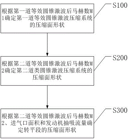
步骤S100,获取第一道等效圆锥激波压缩系统2特性和来流马赫数,根据第一道等效圆锥激波压缩系统2和来流马赫数M0计算第一道等效圆锥激波6后马赫数M1,根据第一道等效圆锥激波6后马赫数M1确定第一道等效圆锥激波压缩系统2的压缩面形状;Step S100, obtaining the characteristics of the first equivalent conical
优选地,第一道等效圆锥激波压缩系统2的设计方法为:设置第一道等效圆锥激波6的圆锥顶点P1,确定第一道等效圆锥激波6圆锥顶点P1距机体表面在垂直方向上的距离和第一道等效圆锥激波6圆锥顶点与第二道类圆锥激波7顶点水平方向的距离;Preferably, the design method of the first equivalent conical shock
根据第一道等效圆锥激波6圆锥顶点距机体表面在垂直方向上的距离和第一道等效圆锥激波6圆锥顶点与第二道类圆锥激波7的圆锥顶点水平方向的距离确定第一道等效圆锥激波6的圆锥半锥角、第一道等效圆锥激波6的激波角、第一道等效圆锥激波6的激波面和机体表面与第一道等效圆锥激波6的交线;Determined according to the vertical distance between the apex of the first equivalent
确定来流马赫数M0、第一道等效圆锥激波6的圆锥半锥角和第一道等效圆锥激波6的激波角之间的函数关系,而后确定第一道等效圆锥激波6的圆锥半锥角、射线角和气流转角的函数关系,从机体表面与第一道等效圆锥激波6面的交线为起点,采用数值积分方法获得第一道等效圆锥激波压缩系统2压缩面的形状和第一道等效圆锥激波6后马赫数M1。Determine the functional relationship between the Mach number M0 of the incoming flow, the cone half-cone angle of the first equivalent
当来流马赫数为M0的气流经过压缩面时,会在压缩面的前端位置产生一道等效圆锥激波前的马赫数。通过对第一道等效圆锥激波6的圆锥半锥角和第一道等效圆锥激波6的激波角等参数进行控制,使得马赫数能够在设计允许的范围内尽可能的衰减。When the incoming airflow with Mach number M0 passes through the compression surface, a Mach number equivalent to the conical shock front will be generated at the front end of the compression surface. By controlling parameters such as the cone half-cone angle of the first
优选地,通过锥型流函数或圆锥激波函数表确定来流马赫数M0、第一道等效圆锥激波6的圆锥半锥角和第一道等效圆锥激波6的激波角之间的函数关系。通过采用该方法,能够实现对第一道等效圆锥激波6的圆锥半锥角和第一道等效圆锥激波6的激波角的精准控制,Preferably, the Mach number M0 of the incoming flow, the cone half-cone angle of the first equivalent
步骤S200,获取第二道类圆锥激波压缩系统3特性,根据第二道类圆锥激波压缩系统3和第一道等效圆锥激波6后马赫数M1M1确定第二道等效圆锥激波后马赫数M2,根据第二道等效圆锥激波后马赫数M2确定第二道类圆锥激波压缩系统3的压缩面形状;Step S200, obtain the characteristics of the second conical shock-
优选地,第二道类圆锥激波压缩系统3的设计方法为:Preferably, the design method of the second similar conical shock
确定第二道类圆锥激波7顶点P3,获取第二道类圆锥激波7顶点P3与第一道等效圆锥激波6顶点在水平方向的距离、第二道类圆锥激波7圆锥顶点与第一道等效圆锥激波6顶点在垂直方向的距离,侧向距离为0,根据产生第一道等效圆锥激波6后马赫数M1、第二道类圆锥激波7的圆锥半锥角和第二道类圆锥激波7的激波角之间的函数关系,结合第二道类圆锥激波7圆锥轴线水平方向的中间点P4,形成第二道等效圆锥激波面;Determine the vertex P3 of the second
根据第二道等效圆锥激波面与压缩面的交线,确定第二道类圆锥激波7面的压缩面的形状和第二道类圆锥激波7压缩面的截止线,并获得第二道类圆锥激波7后马赫数M2。According to the intersection line of the second equivalent conic shock wave surface and the compression surface, determine the shape of the compression surface of the second
当第一道等效圆锥激波6后马赫数M1M1的气流经过压缩面时,会在压缩面的前端位置产生一道类圆锥激波,从而有效衰减来流产生的激波,并进一步改变激波的形状,并进一步降低正激波8前的马赫数。通过对第二道类圆锥激波7的圆锥半锥角和第二道类圆锥激波7的激波角等参数进行控制,使得马赫数能够在设计允许的范围内尽可能的衰减。When the airflow with Mach number M1M1 after the first equivalent
优选地,第一道等效圆锥激波6后马赫数M1、产生第二道类圆锥激波7的圆锥半锥角和第二道类圆锥激波7的激波角之间的函数关系通过锥型流函数或圆锥激波函数表得到;由于第二道类圆锥激波是在第一道等效圆锥激波基础上对气流的再次压缩,第二道类圆锥激波7的激波角通过第一道等效圆锥激波6的圆锥半锥角和第一道类圆锥激波7的激波角的和值计算获得。Preferably, the functional relationship between the Mach number M1 after the first equivalent
优选地,第二道类圆锥激波7压缩面的截止线与第一道等效圆锥激波6压缩面的截止线之间沿水平方向对应点的水平距离,利用P9P10、P4P5和P7P8在水平方向的长度按照抛物线分布获得;截止线P8P5P10和交线P9P4P7之间沿水平方向对应点垂直方向的距离,以产生第二道类圆锥激波7的圆锥半锥角和第二道类圆锥激波7的压缩面曲面上当地沿水平方向的切线角之和为射线角向后上方延伸,延伸的水平长度为截止线P8P5P10和交线P9P4P7之间沿水平方向对应点的水平距离。Preferably, the horizontal distance between the cut-off line of the compression surface of the second
优选地,第二道类圆锥激波7面的压缩面以第一道等效圆锥激波6压缩面的截止线和第二道类圆锥激波7压缩面的截止线为对应曲线,利用两者沿水平方向的对应关系,利用交线P9P10、P4P5和P7P8为引导线,采用三维几何造型软件获得。Preferably, the compression surface of the second
步骤S300,获取进气道1的进气口面积和发动机抽吸流量,根据第二道等效圆锥激波后马赫数M2、进气口面积和发动机抽吸流量确定转平段4的压缩面形状,根据转平段4的压缩面形状确定正激波8后马赫数M3。Step S300, obtain the intake port area and engine suction flow rate of the
优选地,转平段4压缩面形状的获取方法为:Preferably, the method for obtaining the shape of the compression surface in
利用第一道等效圆锥激波6压缩面的截止线P9P4P7和第二道类圆锥激波7压缩面的截止线P8P5P10上任意点沿水平方向的切线方向,设置在通过P6点水平占位处对应点切线方向为水平方向,利用数学函数关系,获得任意P点对应的点P’,利用P点与点P’的对应关系获得进气道1进口前的转平段4的后曲线参数,而后将进口后等曲线作为等直延伸段,最后再与机身融合修型,获得转平段4的压缩面。Use the cut-off line P9P4P7 of the first equivalent
当第二道类圆锥激波7后马赫数M2的气流经过转平段4的压缩面时,会在转平段4的后端、进气道1进口处产生一道正激波8,从而再次衰减来流产生的激波,并进一步改变激波的形状。正激波8的位置与第二道类圆锥激波7后马赫数、进气道1进口面积、进气道1进口段、发动机最大加力状态流量等有关。以此形成的进气道1进口段喉道马赫数一般处于0.65~0.75之间,可使进口前正激波8稍有离体,有溢流存在,保持波系稳定。When the airflow with Mach number M2 after the second
本申请通过在圆锥激波的后面,增加1级类圆锥激波,从而在进气口前构造2道圆锥激波加一道正激波8的三波系形式,激波的形态变化更为平滑,从而有效降低正激波8前的马赫数,进气道1的进气更为稳定,对进口前的三道激波强度合理匹配,提高进气口前的进气道1总压恢复特性,从而拓展飞行器最大马赫数使用范围。In this application, by adding a
作为一种具体实施方式,一种三波系固定压缩面的超音速进气系统,采用上述的进气系统设计方法,包括进气道1、第一道等效圆锥激波压缩系统2、第二道类圆锥激波压缩系统3和转平段4,第一道等效圆锥激波压缩系统2、第二道类圆锥激波压缩系统3和转平段4从前至后依次设置,第一道等效圆锥激波压缩系统2设于飞机机体5上并且第一道等效圆锥激波压缩系统2圆锥的高度从前至后依次增大,第二道类圆锥激波压缩系统3设于飞机机体5上并且第二道类圆锥激波压缩系统3的高度从前至后依次增大,第二道类圆锥激波压缩系统3的高度最低点与第一道等效圆锥激波压缩系统2的高度最高点相同,转平段4设于飞机机体5上并且转平段4的高度从前至后依次增大,转平段4的高度最低点与第二道类圆锥激波压缩系统3的高度最高点相同,转平段4的末端设于进气道1的进气道1进口处。As a specific implementation, a supersonic air intake system with a three-wave fixed compression surface adopts the above air intake system design method, including an air intake 1, a first equivalent conical shock wave compression system 2, a second Cone-like shock wave compression system 3 and flattening section 4, the first equivalent conical shock wave compression system 2, the second conical shock-like compression system 3 and flattening section 4 are arranged in sequence from front to back, the first The equivalent conical shock wave compression system 2 is arranged on the aircraft body 5 and the height of the cones of the first equivalent conical shock wave compression system 2 increases sequentially from front to back, and the second similar conical shock wave compression system 3 is arranged on the aircraft body 5 and the height of the second conical shock-like compression system 3 increases sequentially from front to back, the lowest point of the height of the second conical shock-like compression system 3 is equal to the height of the first equivalent conical shock compression system 2 The highest point is the same, the flattening section 4 is arranged on the aircraft body 5 and the height of the flattening section 4 increases sequentially from front to back, the lowest point of the flattening section 4 is the highest with the height of the second similar conical shock wave compression system 3 The point is the same, the end of turning flat section 4 is located at the inlet of inlet passage 1 of inlet passage 1.
通过在第一道等效圆锥激波压缩系统2和转平段4之间增加第二道类激波压缩系统,从而有效降低正激波8前的马赫数。By adding a second similar shock wave compression system between the first equivalent conical shock
以上所述,仅为本申请的具体实施方式,但本申请的保护范围并不局限于此,任何熟悉本技术领域的技术人员在本申请揭露的技术范围内,可轻易想到的变化或替换,都应涵盖在本申请的保护范围之内。因此,本申请的保护范围应以所述权利要求的保护范围为准。The above is only a specific embodiment of the application, but the scope of protection of the application is not limited thereto. Any person familiar with the technical field can easily think of changes or substitutions within the technical scope disclosed in the application. All should be covered within the scope of protection of this application. Therefore, the protection scope of the present application should be determined by the protection scope of the claims.
Claims (10)
Priority Applications (1)
| Application Number | Priority Date | Filing Date | Title |
|---|---|---|---|
| CN202211589710.3A CN115653754B (en) | 2022-12-12 | 2022-12-12 | Supersonic air inlet system with three-wave system fixed compression surface |
Applications Claiming Priority (1)
| Application Number | Priority Date | Filing Date | Title |
|---|---|---|---|
| CN202211589710.3A CN115653754B (en) | 2022-12-12 | 2022-12-12 | Supersonic air inlet system with three-wave system fixed compression surface |
Publications (2)
| Publication Number | Publication Date |
|---|---|
| CN115653754A true CN115653754A (en) | 2023-01-31 |
| CN115653754B CN115653754B (en) | 2023-04-07 |
Family
ID=85019364
Family Applications (1)
| Application Number | Title | Priority Date | Filing Date |
|---|---|---|---|
| CN202211589710.3A Active CN115653754B (en) | 2022-12-12 | 2022-12-12 | Supersonic air inlet system with three-wave system fixed compression surface |
Country Status (1)
| Country | Link |
|---|---|
| CN (1) | CN115653754B (en) |
Citations (13)
| Publication number | Priority date | Publication date | Assignee | Title |
|---|---|---|---|---|
| US4307743A (en) * | 1980-10-01 | 1981-12-29 | The Boeing Company | Device to start an overcontracted mixed compression supersonic inlet |
| US20080271787A1 (en) * | 2005-12-15 | 2008-11-06 | Henne Preston A | Isentropic compression inlet for supersonic aircraft |
| CN101798961A (en) * | 2010-03-29 | 2010-08-11 | 南京航空航天大学 | Two-stage beveled supersonic speed air inlet lip |
| CN101813027A (en) * | 2010-03-29 | 2010-08-25 | 南京航空航天大学 | Bump air inlet method for realizing integration of unequal-strength wave system with forebody |
| CN102979623A (en) * | 2012-12-31 | 2013-03-20 | 中国人民解放军国防科学技术大学 | Supersonic air inlet and method for determining wall thereof |
| US20130199621A1 (en) * | 2010-05-24 | 2013-08-08 | Jon T. Anderson | Aircraft, propulsion system, and inlet with supersonic compression |
| CN104819056A (en) * | 2015-05-05 | 2015-08-05 | 江西洪都航空工业集团有限责任公司 | DSI air inlet with mix-compression profile surface and construction method of same |
| CN104899418A (en) * | 2015-04-24 | 2015-09-09 | 南京航空航天大学 | Method for predicting unstart oscillation frequency of mixed-compression supersonic and hypersonic speed air inlet passage |
| CN106989891A (en) * | 2017-03-30 | 2017-07-28 | 南京航空航天大学 | Experimental method for accelerated self-starting of a hypersonic inlet |
| CN109209645A (en) * | 2018-11-06 | 2019-01-15 | 中国航空工业集团公司沈阳空气动力研究所 | A kind of three-dimension curved surface compression change geometry inlet structure preparation method |
| US20190170089A1 (en) * | 2017-12-06 | 2019-06-06 | Raytheon Company | Flight vehicle air breathing engine with isolator containing flow diverting ramps |
| US20210200917A1 (en) * | 2019-12-31 | 2021-07-01 | Southwest University Of Science And Technology | Basic flow-field of double straight conical shock waves with controllable downstream flow-field parameters and design method thereof |
| CN115056998A (en) * | 2022-03-26 | 2022-09-16 | 中国空气动力研究与发展中心空天技术研究所 | A design method for longitudinal segmented and graded compression of a cone-guided waverider precursor |
-
2022
- 2022-12-12 CN CN202211589710.3A patent/CN115653754B/en active Active
Patent Citations (13)
| Publication number | Priority date | Publication date | Assignee | Title |
|---|---|---|---|---|
| US4307743A (en) * | 1980-10-01 | 1981-12-29 | The Boeing Company | Device to start an overcontracted mixed compression supersonic inlet |
| US20080271787A1 (en) * | 2005-12-15 | 2008-11-06 | Henne Preston A | Isentropic compression inlet for supersonic aircraft |
| CN101798961A (en) * | 2010-03-29 | 2010-08-11 | 南京航空航天大学 | Two-stage beveled supersonic speed air inlet lip |
| CN101813027A (en) * | 2010-03-29 | 2010-08-25 | 南京航空航天大学 | Bump air inlet method for realizing integration of unequal-strength wave system with forebody |
| US20130199621A1 (en) * | 2010-05-24 | 2013-08-08 | Jon T. Anderson | Aircraft, propulsion system, and inlet with supersonic compression |
| CN102979623A (en) * | 2012-12-31 | 2013-03-20 | 中国人民解放军国防科学技术大学 | Supersonic air inlet and method for determining wall thereof |
| CN104899418A (en) * | 2015-04-24 | 2015-09-09 | 南京航空航天大学 | Method for predicting unstart oscillation frequency of mixed-compression supersonic and hypersonic speed air inlet passage |
| CN104819056A (en) * | 2015-05-05 | 2015-08-05 | 江西洪都航空工业集团有限责任公司 | DSI air inlet with mix-compression profile surface and construction method of same |
| CN106989891A (en) * | 2017-03-30 | 2017-07-28 | 南京航空航天大学 | Experimental method for accelerated self-starting of a hypersonic inlet |
| US20190170089A1 (en) * | 2017-12-06 | 2019-06-06 | Raytheon Company | Flight vehicle air breathing engine with isolator containing flow diverting ramps |
| CN109209645A (en) * | 2018-11-06 | 2019-01-15 | 中国航空工业集团公司沈阳空气动力研究所 | A kind of three-dimension curved surface compression change geometry inlet structure preparation method |
| US20210200917A1 (en) * | 2019-12-31 | 2021-07-01 | Southwest University Of Science And Technology | Basic flow-field of double straight conical shock waves with controllable downstream flow-field parameters and design method thereof |
| CN115056998A (en) * | 2022-03-26 | 2022-09-16 | 中国空气动力研究与发展中心空天技术研究所 | A design method for longitudinal segmented and graded compression of a cone-guided waverider precursor |
Non-Patent Citations (4)
| Title |
|---|
| 杨应凯;: "Bump进气道设计与试验研究" * |
| 王俊琦等: "乘波体与二元高超声速进气道一体化设计研究" * |
| 王向转等;: "二维高超声速进气道优化设计方法研究" * |
| 黎明等: "高超声速二维混压式前体/进气道设计方法研究" * |
Also Published As
| Publication number | Publication date |
|---|---|
| CN115653754B (en) | 2023-04-07 |
Similar Documents
| Publication | Publication Date | Title |
|---|---|---|
| CN109927917B (en) | Integrated design method for internal rotation type wave-rider forebody air inlet channel of supersonic aircraft | |
| CN101813027B (en) | Bump air inlet method for realizing integration of unequal-strength wave system with forebody | |
| CN107191272B (en) | A kind of internal channel method for designing profile of rectangle hypersonic inlet | |
| CN107089340B (en) | With the integrated lower chin formula supersonic speed of precursor or hypersonic inlet and design method | |
| CN105151306B (en) | Method of integrally designing forebody and air intake duct of cone configuration hypersonic flight vehicle | |
| WO2022095163A1 (en) | Internal-external flow decoupled dual-waverider high-speed airbreathing aircraft and generation method therefor | |
| CN110059414B (en) | A two-dimensional blade modeling method with direct control channel | |
| CN114154278A (en) | Parameterized modeling and optimizing method for S-shaped air inlet channel | |
| CN107089341B (en) | With aircraft integrated hypersonic inlet external compression face design method | |
| CN105667812B (en) | Integrated design method of hypersonic vehicle precursor, inlet and wing waveriders | |
| CN115659705B (en) | Fully-parameterized high-stealth air inlet channel design method and high-stealth air inlet channel | |
| CN113800001B (en) | Design method of inner-shrinkage hypersonic air inlet channel integrated with precursor | |
| CN106741976A (en) | A kind of mimetic design method of waverider forebody derived air intake duct integration configuration | |
| CN104912667A (en) | Design method of hypersonic speed internal-contraction air inlet channel carried out in steps | |
| CN107091157B (en) | It is a kind of to determine geometry binary hypersonic inlet and design method | |
| CN115977801B (en) | Design method of double-design-point inlet with wide speed range based on bending shock wave | |
| CN107480392A (en) | A kind of blade shape construction method based on oval heterogeneous deformation | |
| CN115056998A (en) | A design method for longitudinal segmented and graded compression of a cone-guided waverider precursor | |
| CN108301926A (en) | A kind of hypersonic convex turns round contract air intake duct and its design method | |
| CN115653754B (en) | Supersonic air inlet system with three-wave system fixed compression surface | |
| CN117556537A (en) | A turbine blade modeling method based on suction surface profile and channel width distribution | |
| CN201301753Y (en) | Inner wave rider type air inlet channel taking internal and external flow performance into consideration | |
| CN114750973A (en) | A Design Method for Longitudinal Segmentation Multistage Compression of a Kiss-cut Cone Hyperwaverider Precursor | |
| CN111797477B (en) | A forward-swept leading-edge side plate structure with a binary supersonic inlet | |
| CN116204986B (en) | Rapid design method for supersonic bump inlet based on cylindrical fuselage |
Legal Events
| Date | Code | Title | Description |
|---|---|---|---|
| PB01 | Publication | ||
| PB01 | Publication | ||
| SE01 | Entry into force of request for substantive examination | ||
| SE01 | Entry into force of request for substantive examination | ||
| GR01 | Patent grant | ||
| GR01 | Patent grant |