CN115622208A - Self-driven equipment system and charging station thereof - Google Patents
Self-driven equipment system and charging station thereof Download PDFInfo
- Publication number
- CN115622208A CN115622208A CN202110785029.5A CN202110785029A CN115622208A CN 115622208 A CN115622208 A CN 115622208A CN 202110785029 A CN202110785029 A CN 202110785029A CN 115622208 A CN115622208 A CN 115622208A
- Authority
- CN
- China
- Prior art keywords
- self
- low
- alternating current
- charging
- voltage
- Prior art date
- Legal status (The legal status is an assumption and is not a legal conclusion. Google has not performed a legal analysis and makes no representation as to the accuracy of the status listed.)
- Pending
Links
Images


Classifications
-
- B—PERFORMING OPERATIONS; TRANSPORTING
- B60—VEHICLES IN GENERAL
- B60L—PROPULSION OF ELECTRICALLY-PROPELLED VEHICLES; SUPPLYING ELECTRIC POWER FOR AUXILIARY EQUIPMENT OF ELECTRICALLY-PROPELLED VEHICLES; ELECTRODYNAMIC BRAKE SYSTEMS FOR VEHICLES IN GENERAL; MAGNETIC SUSPENSION OR LEVITATION FOR VEHICLES; MONITORING OPERATING VARIABLES OF ELECTRICALLY-PROPELLED VEHICLES; ELECTRIC SAFETY DEVICES FOR ELECTRICALLY-PROPELLED VEHICLES
- B60L53/00—Methods of charging batteries, specially adapted for electric vehicles; Charging stations or on-board charging equipment therefor; Exchange of energy storage elements in electric vehicles
-
- B—PERFORMING OPERATIONS; TRANSPORTING
- B60—VEHICLES IN GENERAL
- B60L—PROPULSION OF ELECTRICALLY-PROPELLED VEHICLES; SUPPLYING ELECTRIC POWER FOR AUXILIARY EQUIPMENT OF ELECTRICALLY-PROPELLED VEHICLES; ELECTRODYNAMIC BRAKE SYSTEMS FOR VEHICLES IN GENERAL; MAGNETIC SUSPENSION OR LEVITATION FOR VEHICLES; MONITORING OPERATING VARIABLES OF ELECTRICALLY-PROPELLED VEHICLES; ELECTRIC SAFETY DEVICES FOR ELECTRICALLY-PROPELLED VEHICLES
- B60L50/00—Electric propulsion with power supplied within the vehicle
- B60L50/50—Electric propulsion with power supplied within the vehicle using propulsion power supplied by batteries or fuel cells
- B60L50/60—Electric propulsion with power supplied within the vehicle using propulsion power supplied by batteries or fuel cells using power supplied by batteries
-
- B—PERFORMING OPERATIONS; TRANSPORTING
- B60—VEHICLES IN GENERAL
- B60L—PROPULSION OF ELECTRICALLY-PROPELLED VEHICLES; SUPPLYING ELECTRIC POWER FOR AUXILIARY EQUIPMENT OF ELECTRICALLY-PROPELLED VEHICLES; ELECTRODYNAMIC BRAKE SYSTEMS FOR VEHICLES IN GENERAL; MAGNETIC SUSPENSION OR LEVITATION FOR VEHICLES; MONITORING OPERATING VARIABLES OF ELECTRICALLY-PROPELLED VEHICLES; ELECTRIC SAFETY DEVICES FOR ELECTRICALLY-PROPELLED VEHICLES
- B60L53/00—Methods of charging batteries, specially adapted for electric vehicles; Charging stations or on-board charging equipment therefor; Exchange of energy storage elements in electric vehicles
- B60L53/10—Methods of charging batteries, specially adapted for electric vehicles; Charging stations or on-board charging equipment therefor; Exchange of energy storage elements in electric vehicles characterised by the energy transfer between the charging station and the vehicle
- B60L53/14—Conductive energy transfer
- B60L53/16—Connectors, e.g. plugs or sockets, specially adapted for charging electric vehicles
-
- B—PERFORMING OPERATIONS; TRANSPORTING
- B60—VEHICLES IN GENERAL
- B60L—PROPULSION OF ELECTRICALLY-PROPELLED VEHICLES; SUPPLYING ELECTRIC POWER FOR AUXILIARY EQUIPMENT OF ELECTRICALLY-PROPELLED VEHICLES; ELECTRODYNAMIC BRAKE SYSTEMS FOR VEHICLES IN GENERAL; MAGNETIC SUSPENSION OR LEVITATION FOR VEHICLES; MONITORING OPERATING VARIABLES OF ELECTRICALLY-PROPELLED VEHICLES; ELECTRIC SAFETY DEVICES FOR ELECTRICALLY-PROPELLED VEHICLES
- B60L53/00—Methods of charging batteries, specially adapted for electric vehicles; Charging stations or on-board charging equipment therefor; Exchange of energy storage elements in electric vehicles
- B60L53/60—Monitoring or controlling charging stations
- B60L53/66—Data transfer between charging stations and vehicles
-
- H—ELECTRICITY
- H02—GENERATION; CONVERSION OR DISTRIBUTION OF ELECTRIC POWER
- H02J—CIRCUIT ARRANGEMENTS OR SYSTEMS FOR SUPPLYING OR DISTRIBUTING ELECTRIC POWER; SYSTEMS FOR STORING ELECTRIC ENERGY
- H02J7/00—Circuit arrangements for charging or depolarising batteries or for supplying loads from batteries
- H02J7/02—Circuit arrangements for charging or depolarising batteries or for supplying loads from batteries for charging batteries from AC mains by converters
-
- H02J7/42—
-
- H02J7/50—
-
- H02J7/70—
-
- H—ELECTRICITY
- H02—GENERATION; CONVERSION OR DISTRIBUTION OF ELECTRIC POWER
- H02M—APPARATUS FOR CONVERSION BETWEEN AC AND AC, BETWEEN AC AND DC, OR BETWEEN DC AND DC, AND FOR USE WITH MAINS OR SIMILAR POWER SUPPLY SYSTEMS; CONVERSION OF DC OR AC INPUT POWER INTO SURGE OUTPUT POWER; CONTROL OR REGULATION THEREOF
- H02M7/00—Conversion of AC power input into DC power output; Conversion of DC power input into AC power output
- H02M7/02—Conversion of AC power input into DC power output without possibility of reversal
- H02M7/04—Conversion of AC power input into DC power output without possibility of reversal by static converters
-
- A—HUMAN NECESSITIES
- A01—AGRICULTURE; FORESTRY; ANIMAL HUSBANDRY; HUNTING; TRAPPING; FISHING
- A01D—HARVESTING; MOWING
- A01D2101/00—Lawn-mowers
-
- A—HUMAN NECESSITIES
- A01—AGRICULTURE; FORESTRY; ANIMAL HUSBANDRY; HUNTING; TRAPPING; FISHING
- A01D—HARVESTING; MOWING
- A01D34/00—Mowers; Mowing apparatus of harvesters
- A01D34/006—Control or measuring arrangements
- A01D34/008—Control or measuring arrangements for automated or remotely controlled operation
-
- B—PERFORMING OPERATIONS; TRANSPORTING
- B60—VEHICLES IN GENERAL
- B60L—PROPULSION OF ELECTRICALLY-PROPELLED VEHICLES; SUPPLYING ELECTRIC POWER FOR AUXILIARY EQUIPMENT OF ELECTRICALLY-PROPELLED VEHICLES; ELECTRODYNAMIC BRAKE SYSTEMS FOR VEHICLES IN GENERAL; MAGNETIC SUSPENSION OR LEVITATION FOR VEHICLES; MONITORING OPERATING VARIABLES OF ELECTRICALLY-PROPELLED VEHICLES; ELECTRIC SAFETY DEVICES FOR ELECTRICALLY-PROPELLED VEHICLES
- B60L2200/00—Type of vehicles
- B60L2200/40—Working vehicles
-
- B—PERFORMING OPERATIONS; TRANSPORTING
- B60—VEHICLES IN GENERAL
- B60L—PROPULSION OF ELECTRICALLY-PROPELLED VEHICLES; SUPPLYING ELECTRIC POWER FOR AUXILIARY EQUIPMENT OF ELECTRICALLY-PROPELLED VEHICLES; ELECTRODYNAMIC BRAKE SYSTEMS FOR VEHICLES IN GENERAL; MAGNETIC SUSPENSION OR LEVITATION FOR VEHICLES; MONITORING OPERATING VARIABLES OF ELECTRICALLY-PROPELLED VEHICLES; ELECTRIC SAFETY DEVICES FOR ELECTRICALLY-PROPELLED VEHICLES
- B60L2210/00—Converter types
- B60L2210/30—AC to DC converters
-
- B—PERFORMING OPERATIONS; TRANSPORTING
- B60—VEHICLES IN GENERAL
- B60L—PROPULSION OF ELECTRICALLY-PROPELLED VEHICLES; SUPPLYING ELECTRIC POWER FOR AUXILIARY EQUIPMENT OF ELECTRICALLY-PROPELLED VEHICLES; ELECTRODYNAMIC BRAKE SYSTEMS FOR VEHICLES IN GENERAL; MAGNETIC SUSPENSION OR LEVITATION FOR VEHICLES; MONITORING OPERATING VARIABLES OF ELECTRICALLY-PROPELLED VEHICLES; ELECTRIC SAFETY DEVICES FOR ELECTRICALLY-PROPELLED VEHICLES
- B60L2260/00—Operating Modes
- B60L2260/20—Drive modes; Transition between modes
- B60L2260/32—Auto pilot mode
-
- H—ELECTRICITY
- H02—GENERATION; CONVERSION OR DISTRIBUTION OF ELECTRIC POWER
- H02J—CIRCUIT ARRANGEMENTS OR SYSTEMS FOR SUPPLYING OR DISTRIBUTING ELECTRIC POWER; SYSTEMS FOR STORING ELECTRIC ENERGY
- H02J2207/00—Indexing scheme relating to details of circuit arrangements for charging or depolarising batteries or for supplying loads from batteries
- H02J2207/20—Charging or discharging characterised by the power electronics converter
-
- Y—GENERAL TAGGING OF NEW TECHNOLOGICAL DEVELOPMENTS; GENERAL TAGGING OF CROSS-SECTIONAL TECHNOLOGIES SPANNING OVER SEVERAL SECTIONS OF THE IPC; TECHNICAL SUBJECTS COVERED BY FORMER USPC CROSS-REFERENCE ART COLLECTIONS [XRACs] AND DIGESTS
- Y02—TECHNOLOGIES OR APPLICATIONS FOR MITIGATION OR ADAPTATION AGAINST CLIMATE CHANGE
- Y02T—CLIMATE CHANGE MITIGATION TECHNOLOGIES RELATED TO TRANSPORTATION
- Y02T10/00—Road transport of goods or passengers
- Y02T10/60—Other road transportation technologies with climate change mitigation effect
- Y02T10/70—Energy storage systems for electromobility, e.g. batteries
-
- Y—GENERAL TAGGING OF NEW TECHNOLOGICAL DEVELOPMENTS; GENERAL TAGGING OF CROSS-SECTIONAL TECHNOLOGIES SPANNING OVER SEVERAL SECTIONS OF THE IPC; TECHNICAL SUBJECTS COVERED BY FORMER USPC CROSS-REFERENCE ART COLLECTIONS [XRACs] AND DIGESTS
- Y02—TECHNOLOGIES OR APPLICATIONS FOR MITIGATION OR ADAPTATION AGAINST CLIMATE CHANGE
- Y02T—CLIMATE CHANGE MITIGATION TECHNOLOGIES RELATED TO TRANSPORTATION
- Y02T10/00—Road transport of goods or passengers
- Y02T10/60—Other road transportation technologies with climate change mitigation effect
- Y02T10/7072—Electromobility specific charging systems or methods for batteries, ultracapacitors, supercapacitors or double-layer capacitors
Landscapes
- Engineering & Computer Science (AREA)
- Power Engineering (AREA)
- Transportation (AREA)
- Mechanical Engineering (AREA)
- Life Sciences & Earth Sciences (AREA)
- Sustainable Development (AREA)
- Sustainable Energy (AREA)
- Environmental Sciences (AREA)
- Charge And Discharge Circuits For Batteries Or The Like (AREA)
- Harvester Elements (AREA)
Abstract
本发明公开了一种自驱动设备系统及其充电站,包括:自驱动设备,能在工作区域内自动行走进行作业;充电站,用于为所述自驱动设备充电;适配器,用于将交流市电转换为低压交流电输出至所述充电站;其中,所述充电站至少包括:输入接口,与所述适配器相连以接入所述低压交流电;第一输出接口,用于将所述低压交流电直接输出至所述自驱动设备;所述自驱动设备至少包括:充电接口,接入所述低压交流电;充电电源电路,将所述低压交流电转换成低压直流电;充电输出接口,输出所述低压直流电为所述自驱动设备供电。采用以上技术方案,能够简化充电站的结构,降低自驱动设备系统的整机成本。
The invention discloses a self-driven equipment system and its charging station, comprising: a self-driven equipment that can automatically walk in a working area to perform operations; a charging station that is used to charge the self-driven equipment; an adapter that is used to connect the AC The mains power is converted into low-voltage alternating current and output to the charging station; wherein, the charging station at least includes: an input interface connected to the adapter to access the low-voltage alternating current; a first output interface for connecting the low-voltage alternating current Directly output to the self-driven device; the self-driven device at least includes: a charging interface, connected to the low-voltage alternating current; a charging power supply circuit, converting the low-voltage alternating current into a low-voltage direct current; a charging output interface, outputting the low-voltage direct current Power the self-propelled device. By adopting the above technical solution, the structure of the charging station can be simplified, and the overall cost of the self-driven equipment system can be reduced.
Description
技术领域technical field
本发明涉及一种园林工具,具体涉及一种自驱动设备系统及其充电站。The invention relates to a garden tool, in particular to a self-driven equipment system and a charging station thereof.
背景技术Background technique
通常,割草机等户外园艺类切割工具上都设置有用于推行的操作把手,操作把手上靠近握持部位设置有方便操作者操作控制的开关盒及控制机构。割草机依靠操作者施加于操作把手的推力于地面行进并进行切割操作,操作者操作这种推行式割草机的劳动强度非常大。随着人工智能的不断发展,能够自行走的自驱动设备也得到了发展。由于自驱动设备可以自动行走,执行预先设置的相关任务,无需人为的操作与干预,极大的节省了人力物力,为操作者带来方便。Usually, outdoor gardening cutting tools such as lawn mowers are provided with operating handles for pushing, and a switch box and a control mechanism are provided on the operating handle near the gripping part for easy operation and control by the operator. The lawn mower relies on the thrust applied by the operator to the operating handle to travel on the ground and perform cutting operations, and the labor intensity for the operator to operate this push-type lawn mower is very high. As artificial intelligence continues to advance, so too have self-propelled devices that can walk on their own. Since the self-driven equipment can walk automatically and perform pre-set related tasks without human operation and intervention, it greatly saves manpower and material resources and brings convenience to the operator.
自驱动设备的出现给用户带来了极大的便利,让用户可以从繁重的园艺护理劳动中解脱出来。目前自驱动设备系统,例如智能割草机系统,还包括充电站和边界线,充电站置于地面,边界线和充电站连接,边界线围绕形成工作区域使智能割草机在工作区域内自动行走进行割草。充电站接入市电后,需要对接入的电压进行转换,将经过转换后的直流电或交流电供自驱动设备充电。此时,充电站需要设置一系列的电压转换电路,对输入电压进行一系列的转换后才能输出至自驱动系统供电池包充电,中间环节相对复杂,充电站的生产成本相对较高。The emergence of self-driven equipment has brought great convenience to users, allowing users to be freed from heavy garden care labor. At present, the self-driven equipment system, such as the intelligent lawn mower system, also includes a charging station and a boundary line. The charging station is placed on the ground, and the boundary line is connected to the charging station. Walk to mow. After the charging station is connected to the mains, the connected voltage needs to be converted, and the converted DC or AC power is used to charge the self-driving equipment. At this time, the charging station needs to be equipped with a series of voltage conversion circuits. After a series of conversions, the input voltage can be output to the self-driving system for charging the battery pack. The intermediate links are relatively complicated, and the production cost of the charging station is relatively high.
发明内容Contents of the invention
为解决现有技术的不足,本发明的目的在于提供一种自驱动设备系统及其充电站能够简化充电站的内部电路,降低自驱动系统的整机生产成本。In order to solve the deficiencies of the prior art, the object of the present invention is to provide a self-driven equipment system and its charging station, which can simplify the internal circuit of the charging station and reduce the production cost of the self-driven system.
为了实现上述目标,本发明采用如下的技术方案:In order to achieve the above object, the present invention adopts the following technical solutions:
一种自驱动设备系统,包括:自驱动设备,能在工作区域内自动行走进行作业;充电站,用于为所述自驱动设备充电;适配器,用于将交流市电转换为第一低压交流电输出至所述充电站;所述充电站至少包括:第一输入接口,用于接入所述第一低压交流电;第一输出接口,用于将所述输入接口接入的所述第一低压交流电直接输出至所述自驱动设备;所述自驱动设备至少包括:充电接口,与所述第一输出接口相连以接入所述第一低压交流电;充电电源电路,与所述第二输入接口相连以将所述第一低压交流电转换成第一低压直流电;第二输出接口,与所述供电模块相连以输出所述第一低压直流电为所述自驱动设备供电。A self-propelled equipment system, comprising: self-propelled equipment capable of automatically walking in a work area to perform operations; a charging station for charging the self-propelled equipment; an adapter for converting AC mains power into a first low-voltage AC power output to the charging station; the charging station at least includes: a first input interface for connecting to the first low-voltage alternating current; a first output interface for connecting the input interface to the first low-voltage The alternating current is directly output to the self-driven device; the self-driven device at least includes: a charging interface connected to the first output interface to access the first low-voltage alternating current; a charging power circuit connected to the second input interface connected to convert the first low-voltage alternating current into a first low-voltage direct current; the second output interface is connected to the power supply module to output the first low-voltage direct current to supply power for the self-driven device.
进一步地,所述充电电源电路至少包括整流电路和滤波电路。Further, the charging power supply circuit at least includes a rectification circuit and a filter circuit.
进一步地,所述自驱动设备还包括:电池组,用于为所述自驱动设备提供电能;所述电池组包括一个或多个可插拔的电池包,所述电池包能够为其他电动工具提供能量来源。Further, the self-propelled device further includes: a battery pack, used to provide electric energy for the self-propelled device; the battery pack includes one or more pluggable battery packs, and the battery pack can provide power for other electric tools. Provide a source of energy.
进一步地,所述适配器至少包括开关电源或隔离变压器的一种。Further, the adapter includes at least one of a switching power supply or an isolation transformer.
进一步地,所述第一低压交流电的电压值的范围设置为大于等于20V且小于等于40V。Further, the voltage range of the first low-voltage alternating current is set to be greater than or equal to 20V and less than or equal to 40V.
进一步地,所述第一低压交流电可设置为方波交流电,正弦交流电,修正弦交流电中的一种。Further, the first low-voltage alternating current can be set as one of square wave alternating current, sinusoidal alternating current, and corrected sinusoidal alternating current.
进一步地,所述充电站还包括:电压转换单元,用于将所述第一输入接口接入的第一低压交流电转换为直流电;第三输出接口,与所述电压转换单元相连以输出所述直流电。Further, the charging station further includes: a voltage conversion unit, configured to convert the first low-voltage alternating current connected to the first input interface into direct current; a third output interface, connected to the voltage conversion unit to output the direct current.
进一步地,所述整流电路设置为电压型全桥逆变电路。Further, the rectification circuit is set as a voltage-type full-bridge inverter circuit.
进一步地,所述滤波电路至少包括一电解电容。Further, the filter circuit includes at least one electrolytic capacitor.
一种充电站,用于为自驱动设备供电,所述自驱动设备能自动在边界线围绕形成的工作区域内行走进行作业;所述充电站包括:第一输入接口,用于接入适配器输出的第一低压交流电;第一输出接口,用于将所述第一输入接口接入的第一低压交流电直接输出至所述自驱动设备;电压转换单元,与所述输入接口连接以将所述输入接口接入的电能转换为直流电;第三输出接口,与所述电压转换单元连接以输出所述直流电为所述边界线供电。A charging station, used to supply power to a self-propelled device, the self-propelled device can automatically walk in the work area formed by the boundary line to perform work; the charging station includes: a first input interface, used to connect to an adapter output the first low-voltage alternating current; the first output interface is used to directly output the first low-voltage alternating current connected to the first input interface to the self-driven device; a voltage conversion unit is connected to the input interface to connect the The electric energy connected to the input interface is converted into direct current; the third output interface is connected with the voltage conversion unit to output the direct current to supply power for the boundary line.
本发明的有益之处在于提供了一种自驱动设备系统及其充电站,能够简化充电站的结构,降低自驱动设备系统的整机成本。The advantage of the present invention is that it provides a self-driven equipment system and its charging station, which can simplify the structure of the charging station and reduce the overall cost of the self-driven equipment system.
附图说明Description of drawings
图1是一种实施方式的自驱动设备系统的结构图;Fig. 1 is a structural diagram of a self-driven device system of an embodiment;
图2是作为实施例之一的智能割草机的电路框图;Fig. 2 is the circuit block diagram of the intelligent lawnmower as one of embodiment;
图3是作为实施例之一的充电站的电路框图;Fig. 3 is a circuit block diagram of a charging station as one of the embodiments;
图4是作为实施例之一的适配器的电路框图。Fig. 4 is a circuit block diagram of an adapter as one of the embodiments.
具体实施方式detailed description
以下结合附图和具体实施例对本发明作具体的介绍。The present invention will be specifically introduced below in conjunction with the accompanying drawings and specific embodiments.
图1所示的一种实施方式的自驱动设备系统,以智能割草机系统为例,所述智能割草机系统100包括智能割草机10、适配器20、充电站30和边界线40。虽然本实施例涉及到智能割草机,但是应该理解本发明不限于所公开的实施例,而是可应用于其他类型的能自动在工作区域内行走进行作业的自驱动设备,包括但不限于智能割草机、扫雪机等。An implementation of the self-driven device system shown in FIG. 1 , taking a smart lawn mower system as an example, the smart
智能割草机10包括沿纵向延伸的壳体11,至少一个车轮(未示出),设置于壳体11底部并可转动;连接到车轮的驱动模组,其提供驱动力以驱动车轮,车轮包括前轮和后轮,可选的,使得前轮为万向轮,后轮设为驱动轮,后轮的数量为两个,前轮的数量可以为两个,也可以设为一个或零个;电池组12,其为智能割草机10提供电能;供电电路,其电连接电池组及驱动模组,使得从电池组输出的电能提供给驱动模组,以驱动该至少一个车轮行走。The
智能割草机10还包括切割刀片(未示出),用于切割草或植被。可选的,驱动模组包括行走电机和切割电机,其中,行走电机用于提供转矩给车轮,从而驱动智能割草机10行进;切割电机用于提供转矩给切割刀片,从而带动切割刀片旋转进行割草作业。可以理解的是,驱动模组可以仅包括一个电机,所述电机同时驱动车轮和切割刀片。The
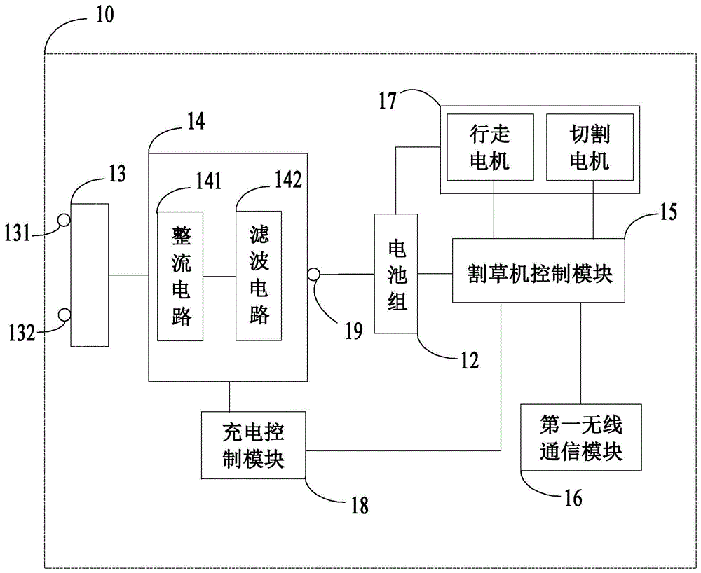
图2示出了作为实施例之一的智能割草机10的电路框图。如图2所示,智能割草机10包括:充电接口13、充电电源电路14、电池组12、割草机控制模块15、第一无线通信模块16、驱动模组17和充电输出接口19。Fig. 2 shows a circuit block diagram of an
充电接口13用于与充电站30连接以接入电能为智能割草机10充电。充电接口13内设置有第一充电端子131和第二充电端子132。The charging
充电电源电路14用于将来自充电接口13的电能转换为适配电池组12的供电电压和供电电流输出。充电电源电路14与充电接口13连接。在一些实施例中,为了给电池组12供电,充电电源电路14将来自充电接口13的电能的低压交流电转换成可供电池组12充电的低压直流电。在一些实施例中,充电电源电路14包括AC/DC转换电路,具体地可包括整流电路141和滤波电路142。The charging
电池组12用于为智能割草机10提供电能。示例性地,电池组12至少用于给驱动模组17供电,当然,电池组12还可以为智能割草机10上的其他电子元器件或电子组件进行供电,例如为割草机控制模块15、第一无线通信模块16供电。在一些实施例中,电池组12包括一个或多个可插拔的电池包,用于给智能割草机10提供能量来源,至少一个电池包还被配置为能为另外一个电动工具提供能量来源。更进一步而言,电池包包括多个串联、并联或者串联与并联结合的电芯单元。电芯单元的电压为4.2V。The
割草机控制模块15至少用于控制切割电机和/或行走电机。在一些实施例中,智能割草机10还包括充电控制模块18,充电控制模块18用于调整充电电源电路14的输入电压和输出电压以适配电池组12。所述充电控制模块18还被配置为调整充电电源电路14的输入电流和输出电流以适配电池组12。在一些具体的实施例中,割草机控制模块15包括控制芯片,例如使MCU、ARM等。The
第一无线通信模块16用于与充电站30进行通信以传输来自割草机控制模块15的数据信息指令等。在一些具体的实施例中,第一无线通信模块16包括WIFI通信模块,当然,在其他的实施例中,其包括蓝牙通信模块或ZigBee通信模块,只要能实现第一无线通信模块16与充电站30建立无线连接并能够传输数据信息指令等的目的即可。The first
边界线40围绕用于规划出智能割草机10的工作区域,其中位于边界线40内的区域为工作区域和位于边界线40外的区域为非工作区域。The
充电站30固定在平面,与边界线40电性连接,充电站30产生边界信号发送给边界线40,边界信号流经边界线40时产生磁场,智能割草机10感应所述磁场并在所述工作区域内行走进行割草作业。可以理解的是,边界信号为电流信号。充电站30还用于供智能割草机10在能源不足时返回补充能量。The charging
图3示出了作为实施例之一的充电站30的电路框图。参考图3所示,充电站30包括:输入接口31、第一输出接口32、边界供电模块33、第二输出接口34、辅助供电模块35、充电站控制模块36和第二无线通信模块37。其中,第二输出接口34,与边界线40电性连接以输出边界信号。第一输出接口32用于与智能割草机10的充电接口13连接以为所述智能割草机10充电。输入接口31,用于接入电能。示例性地,输入接口31与适配器20电性连接。FIG. 3 shows a circuit block diagram of a charging
图4示出了作为实施例之一的充电站30的电路框图。参考图4所示,适配器20与充电站30相连以将电能输送至充电桩30。其中,适配器20包括交流电输入接口21、变压隔离电路22和低压交流电输出接口23。具体地,交流电输入接口21用于接入交流电,在一些实施例中,交流电输入接口21连接电源插头,电源插头插入交流电插座以接入交流市电。交流电输入接口21接入的交流电的取值范围为100V~240V或90V~264V。变压隔离电路22与交流电输入接口21电性连接以将交流市电转换为低压交流电。低压交流电的电压值范围为20V至60V,优选地低压交流电的电压值设置为24V或28V或者56V的低压交流电。具体而言,低压交流电可设置为方波交流电,正弦交流电,修正弦交流电中的一种。低压交流电输出接口23与变压隔离电路22电性连接以输出低压交流电。交流电输入接口21和低压交流电输出接口23电性连接以接入低压交流电至充电站30。具体地,变压隔离电路22可设置为隔离变压器或开关电源电路实现功能。FIG. 4 shows a circuit block diagram of a charging
参见图4所示,变压隔离电路22,连接在交流电输入接口21和低压交流电输出接口23之间,用于将市电转换成低压交流电通过低压交流电输出接口23单向传递至充电站30。作为一种具体的实施方式,变压隔离电路22包括隔离变压器221、第三电容C3和第一电感L1。采用变压隔离电路22设置在交流电输入接口21和低压交流电输出接口23之间,将市电转换成低压交流电通过低压交流电输出接口23单向传递至充电站30,能够避免大电流对智能割草系统带来的影响,同时保护用户的用电安全。As shown in FIG. 4 , the
参见图3所示,辅助供电模块35至少用于为充电站控制模块36和/或第二无线通信模块37供电,辅助供电模块35还可以为充电站30上的其他电子元器件或电子组件进行供电。辅助供电模块35与输入接口31连接,以将输入接口31接入的低压交流电转换为适配于充电站控制模块36和/或第二无线通信模块37的供电电压输出。例如,在一些实施例中,辅助供电模块35将来自输入接口31的电压降到15V以为充电站控制模块36供电,将电源电压降到3.2V以为第二无线通信模块37供电。Referring to Fig. 3, the auxiliary
第二无线通信模块37用于与智能割草机10进行无线通信以传输数据信息指令等,第二无线通信模块37与第一无线通信模块16可通信地连接。在一些具体的实施例中,第二无线通信模块37包括WIFI通信模块,当然,在其他的实施例中,其包括蓝牙通信模块或ZigBee通信模块,只要能实现第二无线通信模块37与充电站建立无线连接并能够传输数据信息指令等的目的即可。The second
边界供电模块33串联在输入接口31和第二输出接口34之间,用于将输入接口31接入的低压交流电转化为边界信号输出。如图3所示,边界供电模块33包括第一电压转换电路331。第一电压转换电路331,与输入接口31电性连接,用于将输入接口31接入的低压交流电转换成供边界线40工作的直流电。The boundary
第一输出接口32与智能割草机10的充电接口13相连以将电能传送至智能割草机10用于供电。第一输出接口32包括第一输出端子321和第二输出端子322。具体而言,第一输出端子321与第一充电端子131电连接,第二输出端子322与第二充电端子132电连接。在本实施中,输入接口31与第一输出接口32之间直接连接。具体而言,输入接口31输入经过适配器20转换后的低压交流电,经过第一输出接口32直接连接至智能割草机10的充电接口13。作为具体实施例的一种,输入接口31接收低压交流电后经过PCB板过度至第一输出接口32。作为具体实施例的另一种,适配器20的低压交流电输出接口23与第一输出接口32的第一输出端子321和第二输出端子322相连,以直接输出低压交流电至自驱动设备10。充电接口13接入低压交流电后经过充电电源电路14对低压交流电进行整流和滤波。具体而言,充电电源电路14包括整流电路141和滤波电路142,用于将低压交流电转换成直流电输出至充电输出接口19以供电池组12充电。在一些实施例中,整流电路141至少包括一个整流桥,滤波电路142至少包括一个滤波电容。其中,低压交流电可选地设置为方波交流电,正弦交流电,修正弦交流电中的一种。The
以上显示和描述了本发明的基本原理、主要特征和优点。本行业的技术人员应该了解,上述实施例不以任何形式限制本发明,凡采用等同替换或等效变换的方式所获得的技术方案,均落在本发明的保护范围内。The basic principles, main features and advantages of the present invention have been shown and described above. Those skilled in the industry should understand that the above-mentioned embodiments do not limit the present invention in any form, and all technical solutions obtained by means of equivalent replacement or equivalent transformation fall within the protection scope of the present invention.
Claims (11)
Priority Applications (3)
| Application Number | Priority Date | Filing Date | Title |
|---|---|---|---|
| CN202110785029.5A CN115622208A (en) | 2021-07-12 | 2021-07-12 | Self-driven equipment system and charging station thereof |
| EP22181452.8A EP4118945B1 (en) | 2021-07-12 | 2022-06-28 | Self-driving device system and charging station |
| US17/854,028 US20230010274A1 (en) | 2021-07-12 | 2022-06-30 | Self-driving device system and charging station |
Applications Claiming Priority (1)
| Application Number | Priority Date | Filing Date | Title |
|---|---|---|---|
| CN202110785029.5A CN115622208A (en) | 2021-07-12 | 2021-07-12 | Self-driven equipment system and charging station thereof |
Publications (1)
| Publication Number | Publication Date |
|---|---|
| CN115622208A true CN115622208A (en) | 2023-01-17 |
Family
ID=82404139
Family Applications (1)
| Application Number | Title | Priority Date | Filing Date |
|---|---|---|---|
| CN202110785029.5A Pending CN115622208A (en) | 2021-07-12 | 2021-07-12 | Self-driven equipment system and charging station thereof |
Country Status (3)
| Country | Link |
|---|---|
| US (1) | US20230010274A1 (en) |
| EP (1) | EP4118945B1 (en) |
| CN (1) | CN115622208A (en) |
Cited By (1)
| Publication number | Priority date | Publication date | Assignee | Title |
|---|---|---|---|---|
| WO2024234949A1 (en) * | 2023-05-16 | 2024-11-21 | 南京泉峰科技有限公司 | Charging station, wheel-type power tool, and gateway device |
Citations (3)
| Publication number | Priority date | Publication date | Assignee | Title |
|---|---|---|---|---|
| CN105467983A (en) * | 2014-08-22 | 2016-04-06 | 扬州维邦园林机械有限公司 | Automatic walking device guiding system and guiding method |
| CN108781704A (en) * | 2017-04-28 | 2018-11-13 | 苏州宝时得电动工具有限公司 | Automatic mower system and its automatic mower |
| WO2019080935A1 (en) * | 2017-10-27 | 2019-05-02 | 苏州宝时得电动工具有限公司 | Automatic working system |
Family Cites Families (5)
| Publication number | Priority date | Publication date | Assignee | Title |
|---|---|---|---|---|
| US7728534B2 (en) * | 2006-10-17 | 2010-06-01 | Mtd Products Inc | Hybrid electric lawnmower |
| ITBO20080040A1 (en) * | 2008-01-23 | 2009-07-24 | Fabrizio Bernini | LAWNMOWER. |
| US9276419B2 (en) * | 2010-12-20 | 2016-03-01 | Positec Power Tools (Suzhou) Co., Ltd. | Robot, a docking system and a docking method |
| DE212015000289U1 (en) * | 2014-12-26 | 2017-07-26 | Hitachi Koki Co., Ltd. | Self-propelled lawnmower |
| CN209403053U (en) * | 2017-12-08 | 2019-09-20 | 苏州宝时得电动工具有限公司 | From mobile device and system |
-
2021
- 2021-07-12 CN CN202110785029.5A patent/CN115622208A/en active Pending
-
2022
- 2022-06-28 EP EP22181452.8A patent/EP4118945B1/en active Active
- 2022-06-30 US US17/854,028 patent/US20230010274A1/en active Pending
Patent Citations (3)
| Publication number | Priority date | Publication date | Assignee | Title |
|---|---|---|---|---|
| CN105467983A (en) * | 2014-08-22 | 2016-04-06 | 扬州维邦园林机械有限公司 | Automatic walking device guiding system and guiding method |
| CN108781704A (en) * | 2017-04-28 | 2018-11-13 | 苏州宝时得电动工具有限公司 | Automatic mower system and its automatic mower |
| WO2019080935A1 (en) * | 2017-10-27 | 2019-05-02 | 苏州宝时得电动工具有限公司 | Automatic working system |
Cited By (1)
| Publication number | Priority date | Publication date | Assignee | Title |
|---|---|---|---|---|
| WO2024234949A1 (en) * | 2023-05-16 | 2024-11-21 | 南京泉峰科技有限公司 | Charging station, wheel-type power tool, and gateway device |
Also Published As
| Publication number | Publication date |
|---|---|
| EP4118945A1 (en) | 2023-01-18 |
| EP4118945B1 (en) | 2024-08-14 |
| US20230010274A1 (en) | 2023-01-12 |
Similar Documents
| Publication | Publication Date | Title |
|---|---|---|
| US12433198B2 (en) | Outdoor walking equipment | |
| WO2020114415A1 (en) | Self-moving device and system | |
| NO992918D0 (en) | Utility system with electric lawnmower as the main unit | |
| CN115622208A (en) | Self-driven equipment system and charging station thereof | |
| CN102386661A (en) | Portable electrifying, charging and discharging equipment for photoelectric device | |
| CN114629190A (en) | Charging station for guiding self-driven equipment to be docked and self-driven equipment system | |
| WO2022127525A1 (en) | Self-driving device system and charging station | |
| US20230389472A1 (en) | Riding lawn mower | |
| CN204361794U (en) | A kind of parallel resonant radio energy transmitting device | |
| CN214479791U (en) | Charger and charging system | |
| CN114788451B (en) | Smart lawn mower system and its charging station | |
| CN114696375A (en) | Self-driven equipment system and charging station thereof | |
| CN114629189A (en) | Self-driven equipment system and charging station thereof | |
| TWI364896B (en) | Inductance wireless recharging system of the intelligent systems | |
| CN114629191A (en) | Self-driven equipment system and charging station thereof | |
| US12543649B2 (en) | Riding lawn mower | |
| CN220682190U (en) | High-power charger power control system | |
| EP4600077A1 (en) | Adapter and charging system comprising same | |
| CN212046912U (en) | Multi-mode wireless charging circuit | |
| CN116774619A (en) | Self-driven equipment system and charging station thereof | |
| CN210608688U (en) | Multi-power supply device special for dispatching data network equipment | |
| CN117715731A (en) | Electric tool | |
| CN209477557U (en) | Wire-feed motor with 220V power output socket | |
| CN119070417A (en) | Portable power supply device and power tool system | |
| CN119362644A (en) | Dual-source power excavator and power supply control method thereof |
Legal Events
| Date | Code | Title | Description |
|---|---|---|---|
| PB01 | Publication | ||
| PB01 | Publication | ||
| SE01 | Entry into force of request for substantive examination | ||
| SE01 | Entry into force of request for substantive examination |