CN115605148A - Surgical probe with independent energy source - Google Patents
Surgical probe with independent energy source Download PDFInfo
- Publication number
- CN115605148A CN115605148A CN202280004165.9A CN202280004165A CN115605148A CN 115605148 A CN115605148 A CN 115605148A CN 202280004165 A CN202280004165 A CN 202280004165A CN 115605148 A CN115605148 A CN 115605148A
- Authority
- CN
- China
- Prior art keywords
- probe
- energy source
- tissue
- elongate
- extension
- Prior art date
- Legal status (The legal status is an assumption and is not a legal conclusion. Google has not performed a legal analysis and makes no representation as to the accuracy of the status listed.)
- Pending
Links
Images


Classifications
-
- A—HUMAN NECESSITIES
- A61—MEDICAL OR VETERINARY SCIENCE; HYGIENE
- A61B—DIAGNOSIS; SURGERY; IDENTIFICATION
- A61B17/00—Surgical instruments, devices or methods
- A61B17/32—Surgical cutting instruments
- A61B17/3203—Fluid jet cutting instruments
-
- A—HUMAN NECESSITIES
- A61—MEDICAL OR VETERINARY SCIENCE; HYGIENE
- A61B—DIAGNOSIS; SURGERY; IDENTIFICATION
- A61B18/00—Surgical instruments, devices or methods for transferring non-mechanical forms of energy to or from the body
- A61B18/04—Surgical instruments, devices or methods for transferring non-mechanical forms of energy to or from the body by heating
- A61B18/12—Surgical instruments, devices or methods for transferring non-mechanical forms of energy to or from the body by heating by passing a current through the tissue to be heated, e.g. high-frequency current
- A61B18/14—Probes or electrodes therefor
- A61B18/148—Probes or electrodes therefor having a short, rigid shaft for accessing the inner body transcutaneously, e.g. for neurosurgery or arthroscopy
-
- A—HUMAN NECESSITIES
- A61—MEDICAL OR VETERINARY SCIENCE; HYGIENE
- A61B—DIAGNOSIS; SURGERY; IDENTIFICATION
- A61B18/00—Surgical instruments, devices or methods for transferring non-mechanical forms of energy to or from the body
- A61B18/04—Surgical instruments, devices or methods for transferring non-mechanical forms of energy to or from the body by heating
- A61B18/12—Surgical instruments, devices or methods for transferring non-mechanical forms of energy to or from the body by heating by passing a current through the tissue to be heated, e.g. high-frequency current
- A61B18/14—Probes or electrodes therefor
- A61B18/1482—Probes or electrodes therefor having a long rigid shaft for accessing the inner body transcutaneously in minimal invasive surgery, e.g. laparoscopy
-
- A—HUMAN NECESSITIES
- A61—MEDICAL OR VETERINARY SCIENCE; HYGIENE
- A61B—DIAGNOSIS; SURGERY; IDENTIFICATION
- A61B18/00—Surgical instruments, devices or methods for transferring non-mechanical forms of energy to or from the body
- A61B18/04—Surgical instruments, devices or methods for transferring non-mechanical forms of energy to or from the body by heating
- A61B18/12—Surgical instruments, devices or methods for transferring non-mechanical forms of energy to or from the body by heating by passing a current through the tissue to be heated, e.g. high-frequency current
- A61B18/14—Probes or electrodes therefor
- A61B18/1485—Probes or electrodes therefor having a short rigid shaft for accessing the inner body through natural openings
-
- A—HUMAN NECESSITIES
- A61—MEDICAL OR VETERINARY SCIENCE; HYGIENE
- A61B—DIAGNOSIS; SURGERY; IDENTIFICATION
- A61B18/00—Surgical instruments, devices or methods for transferring non-mechanical forms of energy to or from the body
- A61B18/04—Surgical instruments, devices or methods for transferring non-mechanical forms of energy to or from the body by heating
- A61B18/12—Surgical instruments, devices or methods for transferring non-mechanical forms of energy to or from the body by heating by passing a current through the tissue to be heated, e.g. high-frequency current
- A61B18/14—Probes or electrodes therefor
- A61B18/149—Probes or electrodes therefor bow shaped or with rotatable body at cantilever end, e.g. for resectoscopes, or coagulating rollers
-
- A—HUMAN NECESSITIES
- A61—MEDICAL OR VETERINARY SCIENCE; HYGIENE
- A61B—DIAGNOSIS; SURGERY; IDENTIFICATION
- A61B18/00—Surgical instruments, devices or methods for transferring non-mechanical forms of energy to or from the body
- A61B18/04—Surgical instruments, devices or methods for transferring non-mechanical forms of energy to or from the body by heating
- A61B18/12—Surgical instruments, devices or methods for transferring non-mechanical forms of energy to or from the body by heating by passing a current through the tissue to be heated, e.g. high-frequency current
- A61B18/14—Probes or electrodes therefor
- A61B18/1492—Probes or electrodes therefor having a flexible, catheter-like structure, e.g. for heart ablation
-
- A—HUMAN NECESSITIES
- A61—MEDICAL OR VETERINARY SCIENCE; HYGIENE
- A61B—DIAGNOSIS; SURGERY; IDENTIFICATION
- A61B34/00—Computer-aided surgery; Manipulators or robots specially adapted for use in surgery
- A61B34/25—User interfaces for surgical systems
-
- A—HUMAN NECESSITIES
- A61—MEDICAL OR VETERINARY SCIENCE; HYGIENE
- A61B—DIAGNOSIS; SURGERY; IDENTIFICATION
- A61B34/00—Computer-aided surgery; Manipulators or robots specially adapted for use in surgery
- A61B34/30—Surgical robots
-
- A—HUMAN NECESSITIES
- A61—MEDICAL OR VETERINARY SCIENCE; HYGIENE
- A61B—DIAGNOSIS; SURGERY; IDENTIFICATION
- A61B34/00—Computer-aided surgery; Manipulators or robots specially adapted for use in surgery
- A61B34/30—Surgical robots
- A61B34/37—Leader-follower robots
-
- A—HUMAN NECESSITIES
- A61—MEDICAL OR VETERINARY SCIENCE; HYGIENE
- A61B—DIAGNOSIS; SURGERY; IDENTIFICATION
- A61B34/00—Computer-aided surgery; Manipulators or robots specially adapted for use in surgery
- A61B34/70—Manipulators specially adapted for use in surgery
-
- A—HUMAN NECESSITIES
- A61—MEDICAL OR VETERINARY SCIENCE; HYGIENE
- A61B—DIAGNOSIS; SURGERY; IDENTIFICATION
- A61B34/00—Computer-aided surgery; Manipulators or robots specially adapted for use in surgery
- A61B34/70—Manipulators specially adapted for use in surgery
- A61B34/74—Manipulators with manual electric input means
-
- A—HUMAN NECESSITIES
- A61—MEDICAL OR VETERINARY SCIENCE; HYGIENE
- A61B—DIAGNOSIS; SURGERY; IDENTIFICATION
- A61B18/00—Surgical instruments, devices or methods for transferring non-mechanical forms of energy to or from the body
- A61B18/02—Surgical instruments, devices or methods for transferring non-mechanical forms of energy to or from the body by cooling, e.g. cryogenic techniques
-
- A—HUMAN NECESSITIES
- A61—MEDICAL OR VETERINARY SCIENCE; HYGIENE
- A61B—DIAGNOSIS; SURGERY; IDENTIFICATION
- A61B18/00—Surgical instruments, devices or methods for transferring non-mechanical forms of energy to or from the body
- A61B18/04—Surgical instruments, devices or methods for transferring non-mechanical forms of energy to or from the body by heating
- A61B18/042—Surgical instruments, devices or methods for transferring non-mechanical forms of energy to or from the body by heating using additional gas becoming plasma
-
- A—HUMAN NECESSITIES
- A61—MEDICAL OR VETERINARY SCIENCE; HYGIENE
- A61B—DIAGNOSIS; SURGERY; IDENTIFICATION
- A61B18/00—Surgical instruments, devices or methods for transferring non-mechanical forms of energy to or from the body
- A61B18/04—Surgical instruments, devices or methods for transferring non-mechanical forms of energy to or from the body by heating
- A61B18/08—Surgical instruments, devices or methods for transferring non-mechanical forms of energy to or from the body by heating by means of electrically-heated probes
- A61B18/082—Probes or electrodes therefor
-
- A—HUMAN NECESSITIES
- A61—MEDICAL OR VETERINARY SCIENCE; HYGIENE
- A61B—DIAGNOSIS; SURGERY; IDENTIFICATION
- A61B18/00—Surgical instruments, devices or methods for transferring non-mechanical forms of energy to or from the body
- A61B18/04—Surgical instruments, devices or methods for transferring non-mechanical forms of energy to or from the body by heating
- A61B18/12—Surgical instruments, devices or methods for transferring non-mechanical forms of energy to or from the body by heating by passing a current through the tissue to be heated, e.g. high-frequency current
- A61B18/1206—Generators therefor
-
- A—HUMAN NECESSITIES
- A61—MEDICAL OR VETERINARY SCIENCE; HYGIENE
- A61B—DIAGNOSIS; SURGERY; IDENTIFICATION
- A61B18/00—Surgical instruments, devices or methods for transferring non-mechanical forms of energy to or from the body
- A61B2018/00053—Mechanical features of the instrument of device
- A61B2018/00184—Moving parts
- A61B2018/00196—Moving parts reciprocating lengthwise
-
- A—HUMAN NECESSITIES
- A61—MEDICAL OR VETERINARY SCIENCE; HYGIENE
- A61B—DIAGNOSIS; SURGERY; IDENTIFICATION
- A61B18/00—Surgical instruments, devices or methods for transferring non-mechanical forms of energy to or from the body
- A61B2018/00053—Mechanical features of the instrument of device
- A61B2018/00184—Moving parts
- A61B2018/00202—Moving parts rotating
- A61B2018/00208—Moving parts rotating actively driven, e.g. by a motor
-
- A—HUMAN NECESSITIES
- A61—MEDICAL OR VETERINARY SCIENCE; HYGIENE
- A61B—DIAGNOSIS; SURGERY; IDENTIFICATION
- A61B18/00—Surgical instruments, devices or methods for transferring non-mechanical forms of energy to or from the body
- A61B2018/00053—Mechanical features of the instrument of device
- A61B2018/00273—Anchoring means for temporary attachment of a device to tissue
- A61B2018/00279—Anchoring means for temporary attachment of a device to tissue deployable
- A61B2018/00285—Balloons
-
- A—HUMAN NECESSITIES
- A61—MEDICAL OR VETERINARY SCIENCE; HYGIENE
- A61B—DIAGNOSIS; SURGERY; IDENTIFICATION
- A61B18/00—Surgical instruments, devices or methods for transferring non-mechanical forms of energy to or from the body
- A61B2018/00571—Surgical instruments, devices or methods for transferring non-mechanical forms of energy to or from the body for achieving a particular surgical effect
- A61B2018/00601—Cutting
-
- A—HUMAN NECESSITIES
- A61—MEDICAL OR VETERINARY SCIENCE; HYGIENE
- A61B—DIAGNOSIS; SURGERY; IDENTIFICATION
- A61B18/00—Surgical instruments, devices or methods for transferring non-mechanical forms of energy to or from the body
- A61B2018/00636—Sensing and controlling the application of energy
- A61B2018/00773—Sensed parameters
- A61B2018/00875—Resistance or impedance
-
- A—HUMAN NECESSITIES
- A61—MEDICAL OR VETERINARY SCIENCE; HYGIENE
- A61B—DIAGNOSIS; SURGERY; IDENTIFICATION
- A61B18/00—Surgical instruments, devices or methods for transferring non-mechanical forms of energy to or from the body
- A61B18/04—Surgical instruments, devices or methods for transferring non-mechanical forms of energy to or from the body by heating
- A61B2018/044—Surgical instruments, devices or methods for transferring non-mechanical forms of energy to or from the body by heating the surgical action being effected by a circulating hot fluid
-
- A—HUMAN NECESSITIES
- A61—MEDICAL OR VETERINARY SCIENCE; HYGIENE
- A61B—DIAGNOSIS; SURGERY; IDENTIFICATION
- A61B34/00—Computer-aided surgery; Manipulators or robots specially adapted for use in surgery
- A61B34/20—Surgical navigation systems; Devices for tracking or guiding surgical instruments, e.g. for frameless stereotaxis
- A61B2034/2046—Tracking techniques
- A61B2034/2055—Optical tracking systems
-
- A—HUMAN NECESSITIES
- A61—MEDICAL OR VETERINARY SCIENCE; HYGIENE
- A61B—DIAGNOSIS; SURGERY; IDENTIFICATION
- A61B34/00—Computer-aided surgery; Manipulators or robots specially adapted for use in surgery
- A61B34/30—Surgical robots
- A61B2034/302—Surgical robots specifically adapted for manipulations within body cavities, e.g. within abdominal or thoracic cavities
-
- A—HUMAN NECESSITIES
- A61—MEDICAL OR VETERINARY SCIENCE; HYGIENE
- A61B—DIAGNOSIS; SURGERY; IDENTIFICATION
- A61B90/00—Instruments, implements or accessories specially adapted for surgery or diagnosis and not covered by any of the groups A61B1/00 - A61B50/00, e.g. for luxation treatment or for protecting wound edges
- A61B90/06—Measuring instruments not otherwise provided for
- A61B2090/064—Measuring instruments not otherwise provided for for measuring force, pressure or mechanical tension
-
- A—HUMAN NECESSITIES
- A61—MEDICAL OR VETERINARY SCIENCE; HYGIENE
- A61B—DIAGNOSIS; SURGERY; IDENTIFICATION
- A61B90/00—Instruments, implements or accessories specially adapted for surgery or diagnosis and not covered by any of the groups A61B1/00 - A61B50/00, e.g. for luxation treatment or for protecting wound edges
- A61B90/39—Markers, e.g. radio-opaque or breast lesions markers
- A61B2090/3937—Visible markers
-
- A—HUMAN NECESSITIES
- A61—MEDICAL OR VETERINARY SCIENCE; HYGIENE
- A61B—DIAGNOSIS; SURGERY; IDENTIFICATION
- A61B2217/00—General characteristics of surgical instruments
- A61B2217/002—Auxiliary appliance
- A61B2217/005—Auxiliary appliance with suction drainage system
-
- A—HUMAN NECESSITIES
- A61—MEDICAL OR VETERINARY SCIENCE; HYGIENE
- A61B—DIAGNOSIS; SURGERY; IDENTIFICATION
- A61B2217/00—General characteristics of surgical instruments
- A61B2217/002—Auxiliary appliance
- A61B2217/007—Auxiliary appliance with irrigation system
-
- A—HUMAN NECESSITIES
- A61—MEDICAL OR VETERINARY SCIENCE; HYGIENE
- A61B—DIAGNOSIS; SURGERY; IDENTIFICATION
- A61B2218/00—Details of surgical instruments, devices or methods for transferring non-mechanical forms of energy to or from the body
- A61B2218/001—Details of surgical instruments, devices or methods for transferring non-mechanical forms of energy to or from the body having means for irrigation and/or aspiration of substances to and/or from the surgical site
- A61B2218/002—Irrigation
-
- A—HUMAN NECESSITIES
- A61—MEDICAL OR VETERINARY SCIENCE; HYGIENE
- A61B—DIAGNOSIS; SURGERY; IDENTIFICATION
- A61B2218/00—Details of surgical instruments, devices or methods for transferring non-mechanical forms of energy to or from the body
- A61B2218/001—Details of surgical instruments, devices or methods for transferring non-mechanical forms of energy to or from the body having means for irrigation and/or aspiration of substances to and/or from the surgical site
- A61B2218/007—Aspiration
Landscapes
- Health & Medical Sciences (AREA)
- Engineering & Computer Science (AREA)
- Surgery (AREA)
- Life Sciences & Earth Sciences (AREA)
- General Health & Medical Sciences (AREA)
- Heart & Thoracic Surgery (AREA)
- Medical Informatics (AREA)
- Molecular Biology (AREA)
- Animal Behavior & Ethology (AREA)
- Nuclear Medicine, Radiotherapy & Molecular Imaging (AREA)
- Public Health (AREA)
- Veterinary Medicine (AREA)
- Biomedical Technology (AREA)
- Robotics (AREA)
- Physics & Mathematics (AREA)
- Otolaryngology (AREA)
- Plasma & Fusion (AREA)
- Neurology (AREA)
- Neurosurgery (AREA)
- Cardiology (AREA)
- Human Computer Interaction (AREA)
- Surgical Instruments (AREA)
Abstract
The energy source is offset relative to the elongate probe axis by the extension. The amount of deflection of the energy source may be controlled by varying the amount of deflection of the extension. The energy source rotates and translates at the offset distance to ablate tissue. In some embodiments, the probe is configured to receive a second treatment probe that includes a second energy source, wherein the second energy source rotates and translates relative to the first treatment probe, which may improve positioning accuracy and stability. The energy source and the extension may be coupled to the linkage to deflect the energy source and translate and rotate the energy source by different amounts of deflection. The linkage may be coupled to the processor and one or more energy sources that move according to the treatment profile.
Description
Cross-referencing
This application claims benefit from U.S. provisional patent application No. 63/201,250, filed 20/4/2021 on title 35 (e), U.S. code, which is incorporated by reference in its entirety.
Background
Existing methods of tissue ablation using energy sources may be less than ideal in at least some respects. Work in connection with the present disclosure indicates that existing methods may cut tissue with less precision and, at least in some cases, may be somewhat more invasive than ideal. At least some existing methods may position the energy source with less than ideal accuracy, which may result in less than ideal tissue ablation. While robotic methods may provide positioning through computer control, at least some existing robotic systems may not be able to position a processing element as precisely as desired. In addition, other factors, such as tissue variation and movement, can make existing methods less than ideal in at least some circumstances. While treatments using more than one energy source have been proposed, existing methods may, at least in some cases, provide less than ideal coordination and positioning for more than one treatment probe.
SUMMARY
The probes, systems, and methods of the present disclosure provide improved placement of an energy source. In some embodiments, the energy source is offset relative to the elongate probe axis by the extension. The offset of the energy source can be controlled by varying the offset of the extension. The energy source may be offset by a distance and the energy source rotated and translated at the offset distance to ablate tissue. In some embodiments, the probe is configured to receive a second treatment probe comprising a second energy source, wherein the second energy source rotates and translates relative to the first treatment probe, which may improve positioning accuracy and stability. In some embodiments, the energy source and the extension are coupled to the linkage to offset the energy source and translate and rotate the energy source at varying offsets. In some embodiments, the first energy source and the second energy source are configured to move independently.
In some embodiments, the linkage is coupled to one or more of the processor and the energy source that moves according to the treatment profile. In some embodiments, the probe is configured to engage a plurality of drive elements of the robotic arm to move the one or more energy sources. In some embodiments, the robotic arm includes five or more drive elements, and the probe is configured to deflect the energy source, rotate the energy source, translate the energy source, rotate the second energy source, and translate the second energy source through coupling to the five or more elements of the robotic arm.
Is incorporated by reference
All patents, applications, and publications mentioned and identified herein are hereby incorporated by reference in their entirety, and even if mentioned elsewhere in this application are to be considered to be fully incorporated by reference.
Brief Description of Drawings
A better understanding of the features, advantages, and principles of the disclosure will be obtained by reference to the following detailed description that sets forth illustrative embodiments, and the accompanying drawings of which:
fig. 1 shows a front view of a system for performing tissue resection in a patient according to some embodiments of the present disclosure;
fig. 2 schematically illustrates a system for performing tissue resection in a patient according to some embodiments of the present disclosure;
fig. 3A and 3B show perspective views of a common base or bed for supporting one or more robotic arms, according to some embodiments of the present disclosure;
figures 4A and 4B illustrate perspective and side views, respectively, of a system including a mobile base for performing tissue resection in a patient according to some embodiments of the present disclosure;
FIGS. 5A and 5B show top views of a coupler between a processing probe and a first robotic arm, where FIG. 5A shows the processing probe and the first robotic arm uncoupled and FIG. 5B shows the processing probe and the first robotic arm coupled, according to some embodiments of the present disclosure;
FIG. 6A shows a drive element for a robotic arm coupled to a surgical probe according to an embodiment of the present disclosure;
FIG. 6B illustrates coupling of a robotic arm to a handling probe according to some embodiments;
FIG. 7 illustrates a probe including an energy source having a variable offset relative to an elongate axis of the probe, in accordance with some embodiments;
FIG. 8 shows the probe as in FIG. 7 in a compact configuration with the energy source positioned toward the elongate axis of the probe, in accordance with some embodiments;
figure 9 shows an isometric view of the probe as in figures 8 and 9 in a compact configuration, in accordance with some embodiments;
figure 10 shows a cross-sectional view of the probe of figures 7-9 according to some embodiments;
FIG. 11 illustrates an internal drive structure of the probe of FIGS. 7-10 in accordance with some embodiments;
12A and 12B show top and side views, respectively, of a probe including a variable offset energy source configured for manual use, according to some embodiments;
13A-13C illustrate cross-sectional views of a probe including an asymmetric inner structure that provides rotational stability, according to some embodiments;
14A and 14B illustrate a push-pull type configuration for biasing an energy source, according to some embodiments;
15A-15D illustrate surface followers (surface followers) that position an energy source relative to a depth from a tissue surface contour according to some embodiments;
16A-16C illustrate an energy source coupled to a surface follower having a pivot proximate a tissue follower surface according to some embodiments;
17A-17C illustrate an energy source coupled to a surface follower, where the energy source has a variable extension depth from the follower to tissue, according to some embodiments;
FIG. 18A illustrates deflection of a flexible link to deflect an energy source via an interlocking structure to provide rotational stability, according to some embodiments;
FIG. 18B shows a cross-sectional view of the probe as shown in FIG. 18A, according to some embodiments;
FIG. 18C shows a bottom view of the probe of FIGS. 18A-18B, in accordance with some embodiments;
FIG. 18D illustrates deflection of the stylet of FIGS. 18A-18C, wherein the deflection angle relative to the elongate axis of the stylet is greater than 45 degrees, in accordance with some embodiments;
FIGS. 19A and 19B show side and top views, respectively, of a probe with electrocautery wires with a cutting surface extending at an oblique angle relative to the curved member, according to some embodiments;
20A and 20B illustrate an energy source including a mechanical cutting element according to some embodiments;
21A-21F illustrate a variable offset energy source including a variable offset waterjet apparatus and a variable offset evacuation cavity (variable offset evacuation cavity) according to some embodiments;
fig. 22A and 22C illustrate a variable-offset waterjet apparatus and evacuation chamber in a retro-jet (retro-jet) configuration, according to some embodiments; and
fig. 23 shows a method of treating a patient according to some embodiments.
Detailed Description
The following detailed description provides a better understanding of the features and advantages of the invention described in this disclosure, in accordance with the embodiments disclosed herein. Although the detailed description includes many specific embodiments, these are provided as examples only and should not be construed as limiting the scope of the invention disclosed herein.
The systems and methods of the present disclosure are well suited for use with a wide variety of probes and diagnostic and surgical procedures. Although reference is made to a probe for prostate surgery comprising an energy source, the present disclosure is well suited for use with many types of probes inserted into many types of tissues, cavities (cavities) and cavities (lumens), such as blood vessel cavities, nasal cavities and cavities, urinary cavities, gastric cavities, airways, esophageal cavities, transesophageal cavities, intestinal cavities, anal cavities, vaginal cavities, transabdominal cavities, abdominal cavities, renal surgeries, ureteral surgeries, kidney stones, prostate surgeries, tumor surgeries, cancer surgeries, brain surgeries, cardiac surgeries, eye surgeries, conjunctival surgeries, liver surgeries, gall bladder surgeries, spinal surgeries, bone surgeries, arthroscopic surgeries, liposuction, colonoscopy, intubation tubes, minimally invasive incisions, minimally invasive surgeries, and the like.
The system and method of the present disclosure is well suited for combination with existing probes (e.g., imaging probes and processing probes). Examples of such probes include, for example, laser treatment probes, water jet probes, RF treatment probes, radiation treatment probes, sonication probes, phacoemulsification probes, imaging probes, endoscopic probes, resectoscope (reoscope) probes, ultrasound imaging probes, a-scan ultrasound probes, B-scan ultrasound probes, doppler ultrasound probes, transrectal ultrasound probes, sagittal ultrasound imaging probes, transverse plane ultrasound imaging probes, and transverse and sagittal ultrasound imaging probes.
The systems, methods, and devices of the present disclosure are well suited for integration with many existing surgical procedures, such as water jet prostatectomy, transurethral electrocision of the prostate (TURP), holmium laser prostatectomy (HOLEP), as well as with surgical robotic systems and automated surgery. The following patent applications describe examples of systems, methods, probes, and processes suitable for incorporation in accordance with the present disclosure: PCT/US2013/028441 entitled "AUTOMATED IMAGE-GUIDED TISSUE RESULATION AND TREATMENT" filed on 28.2.2013, which is published as WO 2013/130895; PCT/US2014/054412 entitled "AUTOMATED IMAGE-GUIDED TISSUE RESONATION AND TREATMENT" filed 9/5/2014, published as WO 2015/035249; PCT/US2020/021756 entitled "ROBOTIC ARMS AND METHODS FOR TISSUE RESONATION AND IMAGING," filed on 9.3.2020, which is published as WO/2020/181290; PCT/US2020/058884, published as WO/2021/096741, entitled "SURGICAL PROBES FOR TISSUE RESONATION WITH ROBOTIC ARMS", filed on 11, 4, 2020; PCT/US2021/070760, published as WO/2021/263276, entitled "INTEGRATION OF ROBOTIC ARMS WITH SURGICAL PROBES", filed on 23.6.2021; AND PCT/US2021/038175 entitled "SYSTEM AND METHOD FOR DEFINING AND MODIFYING RANGE OF MOTION OF PROBE USED IN PATIENT TREATENT", filed on 21.6.2021, which is published as WO/2021/262565, the entire disclosure OF which is incorporated herein by reference.
In some embodiments, improved positioning accuracy is provided for placement of the energy source. The energy source may comprise any suitable energy source, such as an electrode, a ring electrode, a laser source, a mechanical shears (mechanical cutter), an ultrasonic probe, a cavitation ultrasonic probe, a water jet (e.g., a fixed pressure water jet), a plasma, steam, a morcellator (morcellator), a transurethral needle, photo ablation (photo ablation), water jet evacuation (water jet evaluation). The energy source may be combined with other processes and compounds, such as photochemical processing agents.
The probe including the energy source may be configured in a variety of ways, and may include a force sensor to detect tissue resistance and adjust one or more of the following in response to the measured tissue resistance: the energy source deflection angle or the amount of energy.
Fig. 1 shows an exemplary embodiment of a system 400 for performing a treatment of a patient. System 400 may include a treatment probe 450 as described herein and an imaging probe 460 as described herein. A treatment probe 450 may be coupled to the first arm 442 and an imaging probe 460 coupled to the second arm 444. One or both of the first arm 442 and the second arm 444 can include a robotic arm, the movement of which can be controlled by one or more computing devices operably coupled with the arm. The treatment probe 450 may include a device for removing target tissue from a target site within a patient. The treatment probe 450 may be configured to deliver energy from the treatment probe 450 to the target tissue sufficient to remove the target tissue. For example, the treatment probe 450 may include an electrosurgical ablation device, a laser ablation device, a transurethral needle ablation device, a water jet ablation device, or any combination thereof. The imaging probe 460 can be configured to deliver energy from the imaging probe 460 to the target tissue sufficient to image the target tissue. For example, the imaging probe 460 may include an ultrasound probe, a magnetic resonance probe, an endoscope, or a fluoroscopy probe. The first arm 442 and the second arm 444 can be configured to be independently adjustable, adjustable according to a fixed relationship, adjustable according to a user-selected relationship, independently lockable, or simultaneously lockable, or any combination thereof. The first arm 442 and the second arm 444 may have multiple degrees of freedom (e.g., six degrees of freedom) to manipulate the treatment probe 450 and the imaging probe 460, respectively. The processing system 400 may be used to perform tissue resection in an organ of a patient (e.g., a prostate of a patient). The patient may be positioned on a patient support 449 (e.g., a bed, table, chair or platform). The treatment probe 450 may be inserted into a target site of a patient along an access axis that coincides with the treatment probe's elongate axis 451. For example, the treatment probe 450 can be configured for insertion into the urethra of a patient in order to position the energy delivery region of the treatment probe within the prostate of the patient. The imaging probe 460 may be inserted into the patient at or adjacent the target site of the patient along an access axis coincident with the elongate axis 461 of the imaging probe. For example, the imaging probe 460 may include a transrectal ultrasound (TRUS) probe configured to be inserted into the rectum of a patient to view the prostate and surrounding tissue of the patient. As shown in fig. 1, first arm 442 and second arm 444 may be covered with sterile drapes (stereo drapes) to provide a sterile operating environment, keep the robotic arms clean, and reduce the risk of damage to the robotic arms. Additional details regarding the various components of the system 400 suitable for incorporation into embodiments as disclosed herein may be found in U.S. patent No. 7,882,841, U.S. patent No. 8,814,921, U.S. patent No. 9,364,251, and PCT publication No. WO2013/130895, the entire disclosures of which are incorporated herein by reference.
Fig. 2 schematically illustrates an embodiment of a system 400 for performing tissue resection in a patient. The system 400 may include a treatment probe 450 as described herein, and may optionally include an imaging probe 460. The processing probe 450 is coupled to the console 420 and the linkage 430. The coupling device 430 may include one or more components of a robotic arm 442. The imaging probe 460 is coupled to an imaging console 490. For example, the imaging probe may be coupled to the second robotic arm 444. The patient handling probe 450 and the imaging probe 460 may be coupled to a common base 440. The patient is supported with a patient support 449. The processing probe 450 is coupled to the base 440 with a first arm 442. The imaging probe 460 is coupled to the base 440 with a second arm 444. As described in greater detail herein, one or both of the first and second arms 442, 444 may include a robotic arm, the movement of which may be controlled by one or more computing devices operably coupled with the arm.
Although a common base is mentioned, the robotic arm may be coupled to a bed rail (bed rail), a console, or any suitable support structure that supports the base of the robotic arm.
In some embodiments, the system 400 includes a user input device 496 coupled to the processor 423 for user manipulation of a surgical instrument on the robotic arm. The user input devices 496 may be located in any suitable place, such as on a console, on a robotic arm, on a mobile base, and there may be one, two, three, four, or more user input devices used in conjunction with the system 400 to provide redundant ways of input, unique input commands, or combinations. In some embodiments, the user input device includes a controller to move the tip of the processing probe or imaging probe in the presence of movement in response to mechanical movement of the user input device. The tip of the probe may be displayed on the display 425 and the user may manipulate the tip of the probe. For example, the user input device may include a 6 degree-of-freedom input controller in which a user can move the input device in 6 degrees of freedom, and the distal end of the probe moves in response to movement of the controller. In some embodiments, the 6 degrees of freedom include three translational degrees of freedom and three rotational degrees of freedom. The processor may, for example, be configured with instructions for switching the probe control between an automatic image-guided process with the energy source and a process with the energy source with user movement of the user input device.
The patient is placed on the patient support 449 so that the treatment probe 450 and ultrasound probe 460 may be inserted into the patient. The patient may be placed in one or more of a number of body positions (e.g., prone, supine, upright, or inclined). In some embodiments, the patient is placed on the lithotomy site, and, for example, stirrups (stirrups) may be used. In some embodiments, the treatment probe 450 is inserted into the patient in a first orientation on a first side of the patient and the imaging probe is inserted into the patient in a second orientation on a second side of the patient. For example, a treatment probe may be inserted into the patient's urethra from the anterior side of the patient, and an imaging probe may be inserted into the patient's intestine transrectally from the posterior side of the patient. The treatment probe and the imaging probe can be placed within a patient's body with one or more of urethral tissue, urethral wall tissue, prostate tissue, intestinal tissue, or intestinal wall tissue extending between the treatment probe and the imaging probe.
The treatment probe 450 and the imaging probe 460 may be inserted into the patient in one or more of a number of ways. During insertion, each of the first and second arms may include a substantially unlocked configuration such that the treatment or imaging probe may be rotated and translated well in order to insert the probe into the patient. The arm may be locked when the probe is inserted to a desired position. In the locked configuration, the probes may be oriented (e.g., parallel, skewed, horizontal, tilted, or non-parallel) relative to each other in one or more of a number of ways. In order to map the image data of the imaging probe to a process probe coordinate reference, it may be helpful to determine the orientation of the probe using an angle sensor as described herein. Having tissue image data mapped to the treatment probe coordinate reference space may allow for accurate targeting and treatment of tissue identified for treatment by an operator (e.g., a physician).
In some embodiments, processing probe 450 is coupled to imaging probe 460 so as to be aligned with probe 450 based on images from imaging probe 460. As shown, the coupling may be accomplished with a common base 440. Alternatively or in combination, the treatment probe and/or imaging probe may include a magnet to maintain alignment of the probe through the patient's tissue. In some embodiments, the first arm 442 is a movable and lockable arm such that the treatment probe 450 can be positioned at a desired location within the patient. When the stylet 450 has been positioned at the desired location on the patient, the first arm 442 can be locked with the arm lock 427. The imaging probe may be coupled to the base 440 with a second arm 444, and the second arm 444 may be used to adjust the alignment of the imaging probe when the treatment probe is locked in place. For example, the second arm 444 may comprise a lockable and movable arm under control of an imaging system or console and user interface. The movable arm 444 may be micro-actuatable such that the imaging probe 460 may be adjusted with small movements, for example, on the order of 1 millimeter or so, relative to the treatment probe 450.
In some embodiments, processing probe 450 and imaging probe 460 are coupled to an angle sensor so that processing can be controlled based on the alignment of imaging probe 460 and processing probe 450. The first angle sensor 495 may be coupled to the treatment probe 450 with the support 438. The second angle sensor 497 may be coupled to the imaging probe 460. The angle sensor may comprise one or more of many types of angle sensors. For example, the angle sensor may include an goniometer, an accelerometer, and combinations thereof. In some embodiments, the first angle sensor 495 comprises a three-dimensional accelerometer to determine the orientation of the treatment probe 450 in three dimensions. In some embodiments, the second angle sensor 497 may include a three dimensional accelerometer to determine the orientation of the imaging probe 460 in three dimensions. Alternatively or in combination, the first angle sensor 495 may comprise an goniometer to determine the angle of the treatment probe 450 along the elongate axis 451 of the treatment probe. The second angle sensor 497 may include a goniometer to determine the angle of the imaging probe 460 along the elongate axis 461 of the imaging probe 460. The first angle sensor 495 is coupled to the controller 424 of the processing console 420. The second angle sensor 497 of the imaging probe is coupled to the processor 492 of the imaging console 490. Alternatively or in combination, the second angle sensor 497 may be coupled to the controller 424 of the processing console 420.
The console 420 includes a display 425 coupled to the processor system in the means for controlling the treatment probe 450. The console 420 includes a processor 423 with a memory 421. The communication circuit 422 is coupled to the processor 423 and the controller 424. The communication circuitry 422 is coupled to the imaging console 490 via the imaging console's communication circuitry 494. An arm lock 427 of the console 420 may be coupled to the first arm 442 to lock the first arm 422 or allow the first arm 422 to be freely movable to insert the probe 450 into the patient.
Optionally, the console 420 can include components of an endoscope 426, the endoscope 426 being coupled to the anchor 24 of the treatment probe 450. The endoscope 426 may include components of the console 420 and the endoscope, along with the probe 450, may be inserted to treat a patient.
In some embodiments, the console 420 includes an impedance sensor circuit 220 coupled to the energy source to measure the impedance of tissue treated with energy from the energy source. In some embodiments, the energy source comprises an electrode, and the electrode comprises an impedance sensor. In some embodiments, the processor is configured with instructions to adjust the amount of energy from the energy source in response to the magnitude of the impedance. In some embodiments, the processor is configured with instructions to adjust an amount of deflection of the extension and an amount of offset of the energy source relative to the elongate axis in response to the impedance.
In some embodiments, the console 420 includes a force sensor circuit 210 coupled to a force sensor on the processing probe. For example, a force sensor may be coupled to the extension to measure tissue resistance related to deflection of the extension. In some embodiments, a force sensor is coupled to the link to measure tissue resistance related to movement of the energy source away from the elongate axis. In some embodiments, a force sensor is coupled to the energy source to measure tissue resistance related to a positioning distance of the energy source relative to the elongate axis. In some embodiments, the force sensor is configured to measure tissue resistance related to an amount of energy delivery from the energy source.
Optionally, the console 420 may include one or more modules operatively coupled with the treatment probe 450 to control aspects of the treatment performed with the treatment probe. For example, the console 420 may include one or more of the following: an energy source 22 to provide energy to the treatment probe, a balloon inflation control 26 to effect inflation of a balloon used to anchor the treatment probe at the target treatment site, an infusion/irrigation control 28 to control infusion and irrigation of the probe, a suction control 30 to control suction by the probe, an insufflation control 32 to control insufflation of the target treatment site (e.g., prostate), or a light source 33 (e.g., a source of infrared, visible, or ultraviolet light) to provide light energy to the treatment probe.
The processor, controller and control electronics and circuitry may include one or more of a number of suitable components, such as one or more processors, one or more Field Programmable Gate Arrays (FPGAs), and one or more memory storage devices. In some embodiments, the control electronics control a control panel of a graphical user interface (hereinafter "GUI") to provide pre-operative planning and to provide user control of the surgical procedure according to user-specified treatment parameters.
The treatment probe 450 may include an anchor 24. The anchor 24 can anchor the distal end of the probe 450 as the energy probe 450 is delivered to the energy delivery region 20. In some embodiments, the probe includes a first energy source 250, and the first energy source 250 can treat tissue with an offset distance 252 relative to the elongate axis 451 of the probe, such as by deflection of an extension as described herein. The processor may be configured with instructions for performing 3D volumetric ablation of tissue by rotation, translation, and displacement of the energy source 250 in response to computer control. The probe 450 may include a second energy source, such as the nozzle 200, as described herein.
The treatment probe 450 may be coupled to the first arm 442 with a linkage 430. The coupling device 430 may include components that move the energy delivery region 20 to a desired target location of the patient, for example, based on an image of the patient. Coupling 430 may include a first portion 432, a second portion 434, and a third portion 436. First portion 432 may include a substantially fixed anchor portion. The substantially fixed anchor portion 432 may be fixed to a support 438. The support 438 may comprise a frame of reference for the coupling device 430. The support 438 may include a rigid chassis or frame or housing to rigidly and securely couple the first arm 442 to the processing probe 450. First portion 432 may remain substantially stationary while second portion 434 and third portion 436 may move to direct energy from probe 450 to the patient. The first portion 432 may be fixed to a substantially constant distance 437 from the anchor 24. A substantially fixed distance 437 between the anchor 24 and the fixed first portion 432 of the coupling device allows the process to be accurately placed. The first portion 432 can include a linear actuator to accurately position a second energy source (such as the high pressure nozzle 200 in the energy delivery region 20) at a desired axial location along the elongate axis 451 of the treatment probe 450. Additional actuators and linkages may be provided and operably coupled to the processor to shift, rotate, and translate the first energy source 250 as described herein.
The elongate shaft 451 of the treatment probe 450 generally extends between the proximal portion of the probe 450 near the coupling device 430 to the distal end to which the anchor 24 is attached. The third portion 436 may control the angle of rotation 453 about the elongate axis 451. The distance 439 between the energy delivery region 20 and the first portion 432 of the coupling device may vary relative to the anchor 24 during treatment of the patient. The distance 439 can be adjusted in translation 418 of the stylet in response to computer control for setting the target position along the elongate axis 451 of the treatment stylet. In some embodiments, the first portion of the coupling remains stationary while the second portion 434 adjusts the positioning of the energy delivery zone 20 along the axis 451. The third portion 436 of the coupling device adjusts the angle 453 about the axis in response to the controller 424 so that the distance along the axis at the angle of treatment can be controlled very precisely relative to the anchor 24. The probe 450 may include a rigid member, such as a ridge (spine) extending between the support 438 and the anchor 24, such that the distance from the coupling device 430 to the anchor 24 remains substantially constant during treatment. As described herein, the processing probe 450 is coupled to a processing component to allow processing with one or more forms of energy, such as mechanical energy from a jet, electrical energy from an electrode, or optical energy from a light source (e.g., a laser source). The light source may comprise infrared, visible or ultraviolet light. The energy delivery region 20 can be moved under the control of the coupling device 430 to deliver a desired form of energy to the target tissue of the patient.
To facilitate precise control of the treatment probe and/or imaging probe during treatment of the patient, one or more of the treatment probe or imaging probe may be coupled to a robotic, computer-controllable arm. For example, referring to the system 400 shown in fig. 2, one or both of the first arm 442 coupled to the treatment probe 450 and the second arm 444 coupled to the imaging probe 460 as described herein may comprise a robotic, computer-controllable arm. The robotic arm may be operably coupled with one or more computing devices configured to control movement of the robotic arm. For example, the first robotic arm 442 may be operably coupled with the processor 423 of the console 420, or the second robotic arm 444 may be operably coupled with the processor 492 of the imaging console 490 and/or the processor 423 of the console 420. One or more computing devices (e.g., processors 423 and 492) may include computer-executable instructions for controlling movement of one or more robotic arms. The first and second robotic arms may be substantially similar in construction and function, or they may be different to accommodate specific functional requirements for controlling movement of the processing probe and the imaging probe.
The robotic arm may include 6 or 7 or more joints to allow the arm to move under computer control. Suitable robotic arms are commercially available from a number of manufacturers (e.g., roboDK corporation, kinova corporation, and a number of other manufacturers).
One or more computing devices operably coupled to the first and second robotic arms may be configured to automatically control movement of the processing probe and/or the imaging probe. For example, the robotic arm may be configured to automatically adjust the positioning and/or orientation of the treatment probe and/or imaging probe during treatment of the patient according to one or more preprogrammed parameters. The robotic arm may be configured to automatically move the treatment probe and/or the imaging probe along a pre-planned or programmed treatment or scan profile, which may be stored in memory of one or more computing devices. Alternatively or additionally, automatic adjustment of the robotic arm, the one or more computing devices may be configured to control movement of the processing probe and/or the imaging probe in response to user input (e.g., through a graphical user interface of the processing apparatus). Alternatively or additionally, automatic adjustment of the robotic arm, the one or more computing devices may be configured to control movement of the processing probe and/or imaging probe in response to real-time positioning information, e.g., in response to anatomical structures identified in one or more images captured by the imaging probe or other imaging source (from which an allowable range of motion of the processing probe and/or imaging probe may be established) and/or positioning information from the processing probe and/or imaging probe from one or more sensors coupled to the probe and/or robotic arm.
Fig. 3A and 3B show an exemplary embodiment of a common base or pedestal 440 for supporting one or more robotic arms of an image-guided processing system as disclosed herein, and the processing system may include a probe 450 as described herein. Fig. 3A shows a patient support 449 including one or more rails (rails) 452. Patient support 449 may include a surgical console or platform. One or more robotic arms associated with one or more of the processing probes or imaging probes may be mounted to the rails 452 such that the rails function as a common base 440. Fig. 3B shows a common base 440 including a floor support 454, the floor support 454 configured to be coupled to a first robotic arm connected to a handling probe and/or a second robotic arm connected to an imaging probe. The floor support 454 may be positioned between the legs of the patient during the treatment process.
Fig. 4A and 4B illustrate an embodiment of a processing system 400 including a motion base 470 as described herein. Fig. 4A is a front view of the processing system 400 and fig. 4B is a side view of the processing system 400. The handling system 400 may include a handling probe 450 coupled to the first robotic arm 442 and an imaging probe 460 coupled to the second robotic arm 444. The first and second robotic arms 442, 444 each include proximal and distal ends that are coupled to the processing probe 450 and the imaging probe 460, respectively, and proximal ends that are coupled to a common base 440 that includes a moving base 470. The first robotic arm 442 may include a first arm coupling structure 504 coupled to a handling probe 450, and the second robotic arm 444 may include a second arm coupling structure 505 coupled to an imaging probe 460. The treatment probe 450 may be coupled to a distal end of the first robotic arm 442 via an attachment apparatus 500, the attachment apparatus 500 may include a linkage configured to effect movement (e.g., rotation, translation, pitch, etc.) of the treatment probe as described herein. The coupling of the handling probe 450 to the first robotic arm 442 may be fixed, releasable, or user adjustable. Similarly, the coupling of the imaging probe 460 to the second robotic arm 444 may be fixed, releasable, or user adjustable.
The first robot arm 442 may articulate at one or more first arm joints 443. The imaging arm 444 may be articulated at one or more second arm joints 445. Each arm joint 443 or 445 may be operably coupled with a computer-controllable actuator (e.g., a stepper motor) to effect movement at the joint. Each arm joint 443 or 445 may include one of a variety of motion joints including, but not limited to, prismatic, backspin, parallel cylindrical, spherical, planar, edge slider, cylindrical slider, point slider, spherical slider, or crossed cylindrical joints, or any combination thereof. Further, each arm joint 443 or 445 may include linear, orthogonal, rotational, torsional, or supination joints, or any combination thereof.
As described herein, the system 400 may also include a console 420 that may be supported by a mobile support 480 separate from the mobile base 470. The console 420 may be operably coupled with a motion base 470 via a power and communications cable 475 to allow control of a processing probe 450 coupled to the motion base via the first robotic arm. The treatment console 420 includes a processor and memory having stored thereon computer-executable instructions for execution by the processor to control various modules or functions of the treatment console (e.g., energy source, infusion/irrigation control, aspiration control), and other components as described herein with reference to fig. 2. The processing console 420 may also include a display 425 in communication with the processor. The display 425 may be configured to display, for example, one or more of the following: a subject vital sign, such as heart rate, respiratory rate, temperature, blood pressure, oxygen saturation, or any physiological parameter or any combination thereof; the status of the surgical procedure; one or more previously captured images or image sequences of the treatment site from one or more views; one or more real-time images or image sequences of the treatment site from one or more views acquired by imaging probe 460; a set of treatment parameters including, but not limited to, treatment mode (e.g., cutting or coagulation), treatment intensity, time elapsed during treatment, time remaining during treatment, treatment depth, area or volume of treatment sites that have been treated, area of treatment sites that will be treated, area or volume of treatment sites that will not be treated, positional information of treatment probe 450 or imaging probe 460, or both; process adjustment controls, such as means to adjust the depth of treatment, the intensity of treatment, the position and/or orientation of the treatment probe 450, the imaging depth, or the position and/or orientation of the imaging probe 460, or any combination thereof; or system configuration parameters.
The mobile base 470 may also include one or more computing devices to control the operation of one or more robotic arms. For example, the mobile base may include a processor and a memory having stored thereon computer-executable instructions for execution by one or more processors. The memory may have instructions stored thereon for operating one or more robotic arms coupled to the mobile base. The processor may be operatively coupled with the robotic arm via suitable electromechanical components to effect movement of the robotic arm. For example, each of the one or more joints of the robotic arm may include a stepper motor, and the processor may be operably coupled with the stepper motor at each joint to actuate the motor in a specified direction by a specified increment. Alternatively, one or more robotic arms may be operably coupled to one or more processors of the console 420 or a separate imaging console (e.g., the imaging console 490 shown in fig. 2), wherein the one or more console processors may be configured to execute instructions for controlling movement of the one or more robotic arms, and may communicate the instructions to the robotic arms via communication circuitry (such as the communication circuitry 422 of the console 420 or the communication circuitry 494 of the console 490 shown in fig. 2). Computer-executable instructions for controlling movement of the robotic arm may be preprogrammed and stored on the memory, or may be provided by a user via one or more user inputs prior to or during treatment of a patient using the treatment system.
One or more computing devices operably coupled with the first and/or second robotic arms may be configured to control movement of the arms to adjust pitch, yaw, roll, and/or linear positioning of the treatment probe and/or imaging probe along the target site.
The motion base 470 may include one or more user input devices to enable a user to control the movement of the robotic arm under computer instructions. For example, as shown in fig. 4A and 4B, the mobile base may include a keyboard 474 and/or a foot switch 471 that is operatively coupled to the mobile base via a foot switch cable 472. Keyboard 474 and foot switch 471 can, independently or in combination, be configured to control the operation of first robotic arm 442 and/or second robotic arm 444, e.g., via articulation of one or both robotic arms at one or more joints. The keyboard and foot pedal may be in communication with one or more processors configured to control movement of the robotic arm. When a user inputs instructions into the keyboard and/or foot pedal, the user instructions may be received by one or more processors, converted into electrical signals, and the electrical signals may be transmitted to one or more computer-controllable actuators operably coupled to one or more robotic arms. The keyboard and/or foot pedal may control movement of one or both arms toward or away from a process location, a location of interest, a predetermined location, or a user-specified location, or any combination thereof.
Optionally, keyboard 474 and foot switch 471 can be configured, independently or in combination, to control the operation of treatment probe 450 and/or imaging probe 460. For example, keyboard 474 and/or foot switch 471 can be configured to start, stop, pause, or resume treatment with the treatment probe. The keyboard 474 and/or foot pedal 471 may be configured to initiate imaging or freezing (freeze), saving, or displaying on the display 425 of an image or sequence of images previously or currently acquired by the imaging probe.
The motion base 470 and the motion support 480 of the console 420 can be independently positioned around a patient supported by the patient support 449 (e.g., a table). For example, the mobile base 470 supporting the first and second robotic arms and the treatment and imaging probes may be positioned between the patient's legs, while the mobile support 480 supporting the console 420 and display 425 may be positioned to the side of the patient, such as near the patient's torso. The mobile base 470 or mobile support 480 may include one or more movable elements, such as a plurality of wheels, that enable the base or support to move. The mobile base 470 may be covered with a sterile drape during the entire process to prevent contamination and fluid ingress.
Fig. 5A and 5B illustrate an exemplary coupling between a handling probe 450 and a first robotic arm 442 as described herein. FIG. 5A shows the handling probe uncoupled from the robotic arm. FIG. 5B shows the handling probe coupled to the robotic arm. As shown, the handling probe 450 may be coupled to the robotic arm 442 with an attachment apparatus 500, which attachment apparatus 500 may include a reusable motor set. The treatment probe 450 may be removably coupled to the attachment device 500. The attachment device may also include a connector 502 configured to couple to the robotic arm and lock the attachment device in place. Robotic arm 442 may include a coupling structure 504 disposed at a distal end of the arm configured to lockingly receive connector 502 of attachment device 500. Once the handling probe and robotic arm are coupled together, movement of the handling probe may be controlled by moving the robotic arm (e.g., by articulating one or more joints of the robotic arm under computer control).
In some embodiments, the handling probe is coupled to the robotic arm via a quick release mechanism such that the coupling between the probe and the robotic arm can be quickly broken to prevent injury to the patient in the event the robotic arm loses position or otherwise fails to operate properly. The handling probe and the robotic arm may be coupled to each other in a number of ways, such as mechanically (e.g., broom clip) and/or magnetically). For example, in the embodiment shown in fig. 5A and 5B, the coupling structure 504 may include a slot 506, the slot 506 having a magnet 508 disposed therein, and the connector 502 may include a ferromagnetic fixture configured to fit within the slot 506 to engage the magnet 508. The coupling structure 504 may also include a latching mechanism 510 to selectively engage or disengage the connector 502 with the magnet 508. For example, as shown in fig. 5A and 5B, the latching mechanism 510 may include a rotatable knob that may be rotated to effect engagement of the magnet 508 of the coupling structure 504 with the connector 502 of the attachment device 500. The latching mechanism may be engaged or disengaged automatically or manually by a user to couple or decouple the attachment apparatus 500 and thus the treatment probe 450 coupled thereto to or from the robotic arm 442, respectively. In some embodiments, the coupling structure 504 may be operably coupled with one or more computing devices configured to control the robotic arm, and the one or more computing devices may include instructions to release the coupling of the coupling structure with the probe when an error is detected in the operation of the robotic arm.
In some embodiments, first robotic arm 442 may be configured to automatically position processing probe 450 in response to sensor position data from one or more of attachment apparatus 500 or coupling structure 504. For example, first robotic arm 442 may be operated in a "seek" mode to locate attached device 500. In some embodiments, the probe includes one or more reference targets and the robotic arm includes corresponding sensors with sufficient resolution and positioning to identify the relative positioning of the probe in 3D space. In some embodiments, a processor is configured with instructions to: when the user holds the probe steady, for example when the probe is positioned inside a patient, the mounting structure on the robotic arm is used to find the treatment probe or imaging probe.
The sensors on the robotic arm, such as first robotic arm 442, and the sensors on the probe, such as the handling probe, may be arranged in a variety of ways, such as described in the following documents: PCT/US2020/021756 entitled "ROBOTIC ARMS AND METHODS FOR TISSUE RESONATION AND IMAGING," filed on 9/3.2020 AND disclosed as WO/2020/181290, which was previously incorporated herein by reference.
The processor may be coupled to sensors near the end of the robotic arm or on the probe to dynamically update the relative position during movement of the robotic arm while seeking to engage the probe on the arm. The sensor on the robotic arm may comprise a plurality of sensors including one or more of: capacitive, capacitive displacement, doppler, inductive, magnetic, optical, radar, sonar, ultrasound or hall effect sensors to determine the relative distance between the robot arm and the probe. In some embodiments, the probe includes a plurality of targets and the sensor is configured to generate a signal in response to a distance from the plurality of targets. Alternatively or in combination, the sensors may be located on the probe and target on the robot arm. In some embodiments, the sensor comprises a close contact mechanical sensor to confirm docking of the probe on or near the robotic arm, e.g., sensing the positioning of the probe relative to the robotic arm when the probe and arm are within a few millimeters of docking with each other. The close-contact mechanical sensor may include one or more of: a micro-switch, a whisker-type touch sensor, or a pinhole contact switch. In some embodiments, the probe and robotic arm include an integrated locking mechanism to provide a non-moving locking engagement at the final contact location. As will be understood by those of ordinary skill in the art, the integrated locking mechanism may include one or more of the following: magnetic elements, electromagnetic elements, latches, screws (e.g., multi turn locking screws or quarter turn locking screws), vacuum, or other mechanical means of reversible attachment.
In some embodiments, multiple sensors are used, such as one or more sensors for a close separation distance between the probe and the robotic arm, one or more sensors for a medium separation distance between the probe and the robotic arm, and one or more sensors for a far separation distance between the probe and the robotic arm. A coarse position sensor may be used to determine the approximate position of the probe (e.g., a beacon). One or more sensors, such as proximity sensors, may be used for fine positional positioning of the probe relative to the robotic arm. In some embodiments, one or more markers on the probe are used with a camera and machine vision to detect the one or more markers.
In some embodiments, a coarse position sensor may be provided, which may be an Infrared (IR) beacon that enables a coarse positioning spatial position for self-guided detection (localization detection) of the robotic arm to the probe. In some cases, a homing (homing) beacon (e.g., an IR beacon) allows homing across a greater distance than a sensor that may rely on visual identification of a fiducial point.
In some embodiments, the docking detection sensor confirms that the robotic arm has engaged or is in close proximity to the probe. As an example, a hall effect sensor may be used in conjunction with a permanent magnet to achieve a sensor output. In some embodiments, the hall effect sensor is noise resistant, non-contact, and has a consistent detection range. Any of a number of different types of hall sensors can be utilized, and in many cases the sensors function as simple switches and linear range measurements and detections, with the total output voltage being set by the supply voltage and varying in proportion to the strength of the magnetic field. This results in a distance measurement between the sensor and the positioning magnet and can be used to measure the distance between the robot arm and the probe and facilitate docking. The sensor and beacon may be located within respective housings of the robotic arm and probe.
In some embodiments, position sensing of the robotic arm is performed by an Inertial Measurement Unit (IMU) which may include up to 9-axis detection. In some cases, a 6-axis IMU may be used for motion detection, vibration detection, positional orientation information, redundancy and backup of primary encoder signals that may be located in joints of a robotic arm. As described herein, the IMU may perform the dual functions of finding a probe for docking with a robotic arm, as well as force detection and motion compensation. The sensors described may be used in conjunction with any of the robotic arms or probes described herein.
According to some embodiments, a process for docking a robotic arm with a probe may include IR beacons that provide coarse positioning and spatial location for self-guided detection, optical sensors of fiducial and observation fiducial on the arm or probe (which may be used to allow fine alignment of the positioning location in the XY plane), and hall effect sensors that detect Z-direction proximity with respect to the docking. The IR beacon allows for greater range finding of the original positioning of the robotic arm relative to the probe. The fiducial and optical sensor may allow for fast, low-latency detection of the 2D position and 2D orientation of the probe by the robotic arm. A user interface, which may be located on the robotic arm, on the probe, or on the robotic arm control unit, may indicate distance, location, docking status, or other information. In some embodiments, the user interface includes one or more visual cues, such as LED indicators, to indicate the relative positioning and/or docking status of the arm and probe.
Although the coupling mechanism shown in fig. 5A and 5B is described in the context of coupling a handling probe to a first robotic arm, a substantially similar mechanism may also be used to couple an imaging probe to a second robotic arm 444. For example, the coupling structure of the second robotic arm 444 may include a similar coupling mechanism for engaging an attachment device connected to the imaging probe.
Fig. 6A and 6B illustrate an exemplary coupling between a handpiece 600 and an instrument device manipulator 602. Throughout the description of the various embodiments, handpiece 600 may include any of a variety of instruments, such as, for example, imaging probes, treatment probes, surgical tools, catheters, energy delivery systems, implants, visualization systems, and other instruments that may be desirable for use during diagnosis or treatment of a patient. Further, although reference is made to handpiece 600 coupled to an actuator, a surgical probe coupled to an actuator may include any suitable probe as described herein. As used throughout the description, reference to instrument device manipulator 602 may refer to a robotic arm. Instrument device manipulator 602 may have one or more motors associated therewith, which may be carried internal or external to instrument device manipulator 602. In some embodiments, instrument device manipulator 602 may carry one, two, three, four, five, six, seven, eight, or more motors. One or more of the motors may have an output shaft that is rotated by the motor. One or more motors of instrument device manipulator 602 may include a coupling (e.g., gears) on the motor output shaft. The coupling may include a pinion, bevel gear, spur gear, helical gear, worm drive gear, planetary gear set, or some other type of coupling. The coupling may be coupled to another coupling associated with the transmission 610, a chain, a belt, or some other type of coupling of the transmission 610 to convert the rotational motion of the motor to motion of one or more portions of the handpiece 600. In some cases, the rotational motion of the motor is converted to rotational motion of a component of the handpiece 600, and in some cases, the rotational output of the motor is converted to linear motion of a component of the handpiece 600. The following figures provide exemplary systems for coupling instrument device manipulator 602 to one or more instruments (e.g., handpiece 600, a probe, an scope, or other instruments).
Fig. 6A shows an exemplary end 604 of an instrument device manipulator 602 having five linkages 606 and electrical ports 608. While the illustrated embodiment shows five linkages 606, it should be understood that instrument device manipulator 602 may have any suitable number of linkages 606, such as two, three, four, five, six, seven, eight, nine, or more. Although the coupling devices 606 are shown as gears, any type or suitable combination of coupling devices 606 may be used. Examples of coupling devices for rotational movement include, but are not limited to, round shafts with flats, round shafts with keyways, square or rectangular shafts, spline couplings (spline couplings), pentagonal shafts, hexagonal shafts, and the like. The coupling 606 may also provide translational movement. The electrical port 608 may provide power and communication to the handpiece 600, for example, to allow signals to be communicated between the handpiece 600 and a computing device that may implement a treatment plan and control actuation of the instruments of the handpiece 600. In some embodiments, the handpiece includes one or more of a force sensor, a force sensor circuit, or an impedance measurement circuit coupled to the electrode, and the electrical port 608 is configured to receive and transmit one or more of the impedance signal or the force measurement signal.
In some embodiments, each of the plurality of linkages 606 includes an output of the instrument device manipulator 602 that includes an engagement structure to couple to a corresponding engagement structure of an input of a transmission described herein. In some embodiments, the engagement structure and corresponding engagement structure comprise a rotatable engagement structure, such as one or more of: pinions, bevel gears, spur gears, helical gears, worm-drive gears, gears in planetary gear sets, shaped shafts (shaped disks), round shafts with flats, round shafts with keyways, square or rectangular shafts, spline couplings, pentagonal shafts, hexagonal shafts, and corresponding structures described herein.
Fig. 6B illustrates an exemplary coupling between handpiece 600 and instrument device manipulator 602. As described herein, the handpiece 600 can include a treatment probe 450 to deliver energy from the first energy source 250 and the second energy source 200. In some embodiments, the handpiece 60 and treatment probe 450 are configured to receive a second treatment probe that includes a second energy source as described herein. The transmission 610 couples the handpiece 600 to the instrument device manipulator 602 and transmits output from one or more motors 612, 614, etc. associated with the instrument device manipulator 602 to the handpiece 600. In some embodiments, the transmission 610 is configured to be decoupled from the instrumentation manipulator 602 and the probe (e.g., handpiece 600) in a stand-alone configuration of the transmission 610, wherein the housing 611 at least partially encloses the transmission. The transmission 610 may include a down or double speed to effectively couple between one or more motors 612 of the instrument device manipulator 602 and the R drive, Z drive, or both, of the handpiece 600 or one or more implements carried by the handpiece, such as, but not limited to, an imaging device, a cutting tool (e.g., a water jet device), an electrode (e.g., an RF electrode), or other energy delivery device. In some cases, transmission 610 may be configured to couple multiple configurations of handpiece 600 to instrument device manipulator 602. For example, the transmission 610 may be configured to receive an output from one or more motors 612 associated with the instrument device manipulator 602 and transmit the motion to any of the plurality of handpieces 600. In this manner, the handpiece 600 need not be manufactured to couple with a particular instrument device manipulator 602, but rather, because the transmission 610 may be configured to couple with both, the handpiece 600 and its associated instrument may be manufactured without regard to the instrument device manipulator 602 to which it may ultimately be coupled.
For any of the numerous embodiments disclosed herein, the transmission 610 may be at least partially enclosed (e.g., encapsulated) within a housing 611, the housing 611 covering the internal components of the transmission 610. The housing 611 may comprise any suitable housing, such as a plastic housing that encloses the internal workings of the transmission and is shown in phantom throughout the figures. In some cases, an output of the instrument device manipulator 602 passes through the housing to couple to an input of the transmission 610. The output of the instrument device manipulator includes an engagement structure to couple to a corresponding engagement structure of the input of the transmission, which may include any suitable shape as described herein, and typically includes a rotatable structure. Similarly, an output of the transmission 610 may extend through the housing to couple with the handpiece 600, wherein the output of the transmission and the input of the handpiece include corresponding engagement structures to couple the handpiece to the transmission of the handpiece as described herein.
Similarly, an input of instrument device manipulator 602 may extend through the housing to couple with instrument device manipulator 602, e.g., through a corresponding engagement structure. Likewise, the input end of the handpiece 600 may extend through the housing 611 to mechanically couple to the transmission 610, such as by corresponding engagement structure.
In any case, one or more of the outputs or inputs may pass through the housing 611 in order to effect coupling between the instrument device manipulator 602, the transmission 610, and/or the handpiece 600. In some cases, instrument device manipulator 602 includes one or more outputs that may extend through the housing. The transmission may include one or more inputs extending through the housing and/or one or more outputs extending through the housing. Similarly, the handpiece 600 may include one or more inputs extending through the housing of the transmission 610.
The handpiece 600 may include any suitable treatment probe 616, such as, for example, a water jet device 618, an RF electrode 644, or other treatment probe, and the handpiece 600 is coupled to the instrument device manipulator 602 by an attachment device that may include a reusable drive 610. The reusable drive 610 may provide advantages because mechanical and electrical precision may be built into the device with minimal impact on the cost of a single process. The handpiece 600 may be removably coupled to the transmission 610, and the transmission 610 may be removably coupled to the instrument device manipulator 602. The removable coupling facilitates interchangeability of similar devices and enables a surgeon to quickly and easily change between different types of instruments according to medical needs. The handpiece 600 can include a position encoder 620, the position encoder 620 configured to transmit signals associated with the position of one or more treatment probes 616, 644. The signal may correspond to a rotation angle, position, orientation, translation, or combination of the processing probes 616, 644. Additional encoders 620 may be provided to transmit signals associated with positioning or orientation such as imaging probes, endoscopes, catheters, lasers, microwaves, and others. Similarly, one or more encoders may be provided in conjunction with instrument device manipulator 602 to determine the position and orientation of instrument device manipulator 602.
In some embodiments, the handpiece 600 is coupled to the transmission 610 through a quick release mechanism such that the coupling between the handpiece 600 and the transmission 610 can be quickly broken to prevent injury to the patient in the event the instrumentation manipulator 602 loses position or otherwise fails to operate properly. The quick-release mechanism may also facilitate quick replacement of the handpiece 600 and instrument, even during a process in which it is desired to attach a replacement instrument to the instrument device manipulator 602 via the transmission 610.
Similarly, transmission 610 may be coupled to instrument device manipulator 602 by a similar mechanism that may provide a quick release. The coupling of the handpiece 600 to the transmission 610 and the coupling of the transmission 610 to the instrumentation manipulator 602 may be performed by similar connection structures or may be different structures. For example, handpiece 600 may be coupled to transmission 610 via a magnetic coupling, while transmission 610 may be coupled to instrument device manipulator 602 via a mechanical locking structure. Other coupling structures may include a slot having a magnet disposed therein, and the mating ferromagnetic fixture may be configured to fit in the slot. The coupling may be provided by a latching mechanism to selectively engage or disengage cooperating coupling members. Further, the coupling structure may include a rotation knob, a lever, a cooperating boss and pocket, a hook, a latch, a pin, or some other suitable type of connector to releasably secure the handpiece 600 to the transmission 610 and to secure the transmission 610 to the instrument device manipulator 602.
As shown, the instrument device manipulator 602 can have two motors 612, three motors, four motors, five motors, or more motors. The right angle drive coupling 622 shown in fig. 6B may be geometrically preferred in certain circumstances involving the arrangement of the couplings that support the arms of the instrumentation manipulator 602. The first motor 612 has an output shaft that carries a coupling device, such as a bevel gear, worm gear, helical gear, or some other configuration. The first electric machine 612 is coupled to a cooperating coupling means of the transmission 610. The transmission 610, in turn, is coupled to an instrument, such as a water jet device 618, and provides rotational motion of the instrument. In some embodiments, the instrument includes a distal end and a proximal end, and a lumen extending between the distal end and the proximal end. The distal end may carry an energy source, such as a nozzle, and the proximal end may be coupled to a high pressure fluid source. In some cases, the instrument remains substantially straight when carried by the transmission 610. In some cases, the instrument fits within a recess formed on the exterior of the transmission 610 to facilitate rapid insertion and removal of the instrument with the transmission 610. The instrument may be held by a holding structure (e.g., a clip, lever, or some other suitable structure) carried by the transmission 610.
The second motor 614 of the instrument device manipulator 602 has an output shaft carrying a coupling, which may be a bevel gear 622, a worm drive, a helical gear, or some other suitable gear. The second motor 614 is coupled to cooperating gears of the transmission 610. The transmission 610 is in turn coupled to an instrument, such as a water jet 618, and is used to provide translational linear motion of the instrument. In some examples, the transmission 610 includes a step-up transmission 610, wherein the rotational output of the transmission 610 is faster than the rotational input of the transmission 610. This may be accomplished, for example, by the driven gear 624 having a smaller pitch circle than the drive gear 626. In some embodiments, driven gear 624 has a smaller number of teeth than drive gear 626. Alternatively, the transmission 610 may be a step-down transmission 610, wherein the driven gear 624 has a larger pitch circle than the meshing drive gear 626. In this case, the driven gear 624 may have more teeth than the drive gear 626, which causes the driven gear 624 to rotate slower than the drive gear 624.
In some embodiments, the first motor 612 and the second motor 614 of the instrument device manipulator 602 are coupled to a single input of the transmission 610. For example, two or more motors of the instrument device manipulator 602 may be coupled together within the transmission 610 to combine their power into a single output shaft. Additionally, the transmission 610 may employ two or more motors and, through gearing or other lever mechanisms, have an output shaft that reduces the input from the two or more motors to result in a greater combined torque, or increases the input from the two or more motors to result in a greater speed. The step down gearing 610 may be useful, for example, for applying clamping force where torque is preferred over speed. The step-up drive 610 may be useful where speed is preferred over torque, such as for ultrasonic motion, burr cutting, friction heating, or other suitable high speed processes.
The transmission 610 may include a right angle transmission 610 in which an output shaft of the instrument device manipulator 602 motor is orthogonal (or substantially orthogonal) to an input shaft of the handpiece 600. For ease of describing the various configurations, the handpiece 600 has a longitudinal axis, and the treatment probe 616 (e.g., a water jet device) extends parallel to the longitudinal axis of the handpiece 600, which is also referred to as the Z-direction. An X-Y plane is orthogonal to the Z direction. In some embodiments, the waterjet device is translated in the Z direction by a second motor (also referred to as a Z drive 630) and rotated about its longitudinal axis by a rotation motor ("R drive") 632. Processing probe 616 is longitudinally translated and/or rotationally oscillated under the instruction of the computing device. The computing device sends a signal to the instrument device manipulator 602 to actuate one or more motors 612, which one or more motors 612 are coupled to the instrument of the handpiece 600 through a linkage. The handpiece 600 has one or more encoders 620, the one or more encoders 620 transmitting a signal (e.g., a position, a location, an orientation, a translation, or some other signal indicative of a parameter of the handpiece 600 or one or more instruments of the handpiece 600) back to the computing device.
The handpiece 600 may be coupled to the transmission 610 in a manner that mechanically couples the R driver 632 and the Z driver 630 with the instruments of the handpiece 600. For example, the drive 610 may include a coupler 634, such as a hexagonal shaft coupler, that receives a correspondingly shaped structure of the handpiece 600 such that when the handpiece 600 is coupled to the drive 610, an instrument of the handpiece 600 is in driving engagement with the drive 610. Other couplers are also contemplated and include, but are not limited to, circular couplers with flats, circular couplers with keyways, square or rectangular couplers, spline couplings, pentagonal couplers, and the like. Thus, the motor of the instrument device manipulator 602 is coupled to the transmission 610, and the transmission 610 transmits the motion of the motor of the instrument device manipulator 602 to the instrument of the handpiece 600. Once coupled, activation of the motor of instrument device manipulator 602 results in either R-drive or Z-drive motion of the instrument of handpiece 600.
In some embodiments, an input of instrument device manipulator 602 may provide articulation of one or more instruments of handpiece 600. For example, an instrument, such as a probe, scope, or other device, may be flexible, have segments, joints, or have other ways of allowing the instrument to articulate. The input of instrument device manipulator 602 may be used to articulate the instrument, such as, for example, by manipulating a wire, such as by tensioning, twisting, compressing, or some other applied force. The instruments of handpiece 600 may be rotated, translated, articulated, or moved in combination in response to the application of force from instrument device manipulator 602.
By way of example, handpiece 600 may carry an energy source as described herein, such as an energy delivery electrode, which in some cases may be RF electrode 644. Third motor 646 of instrument device manipulator 602 can be coupled to RF electrode 644 through an actuator to linearly translate RF electrode 644. Fourth motor 648 may be coupled to RF electrode 644 and configured to provide rotation of RF electrode 644. Fifth motor 650 can be coupled to RF electrode 644 through an actuator and can be used to pivot RF electrode 644 in a direction away from the longitudinal axis of the RF electrode. In other words, at least a portion of RF electrode 644 may pivot, articulate, hinge, and/or bend such that the distal end of RF electrode 644 is not coaxial with the proximal length of the shaft. Such articulation allows the distal tip of RF electrode 644 to move to a more proximal position of tissue spaced from the longitudinal axis of RF electrode 644 in order to ablate tissue with one or more of rotation and translation of the electrode as described herein.
According to some embodiments, the RF electrode 644 is mounted to an extension 654, which extension 654 is pivotally coupled to the shaft 656 at pivot 660. In some cases, the shaft 656 is driven by one or more motors 646, 648 to allow for axial translation and/or rotation about the shaft axis 658. The extension 654 may be coupled to the shaft 656 by any suitable connection (e.g., pivot 660) that allows the extension 654 to be remote from the shaft axis 658. Extension 654 may be moved by any suitable actuator, such as a motor, a pull wire, a heat input, a gear, a shaft, or any other such suitable actuator mechanism.
In some embodiments, shaft 656 carries a microwave ablation device, which may include a power distribution system, an interstitial applicator (applicator) that may be coupled to a microwave generator. The microwave ablation system may be constructed and operated similar to RF electrode 644 described herein.
The electrical system interface device 636 may be carried by the transmission 610 and may transmit, condition, or interpret electrical signals between the instrument device manipulator 602 and the handpiece 600. Electrical system interface device 636 may include one or more electrical connectors to electrically couple handpiece 600 and instrument device manipulator 602 when handpiece 600 is coupled to instrument device manipulator 602 through transmission 610. The electrical system interface device 636 may send electrical power and/or commands to the handpiece 600, such as from a computing system, and may send signals to the instrument device manipulator 602 from the handpiece 600, such as signals associated with force, imaging, volume, positioning, direction, orientation, temperature, or some other parameter. It may also provide signal processing between handpiece 600 and instrument device manipulator 602 and signals communicated to and from system 400. In some embodiments, the handpiece 600 includes one or more encoders 620 for transmitting signals associated with parameters of the handpiece 600 to a computing system. It may also send electrical energy to one or more of the probes, for example for energizing lights, RF transmitters, thermal ablation devices, or other devices that require electrical power to operate effectively.
An imaging device, such as a cystoscope 642, ultrasound probe, or other type of imaging device, may be carried by the handpiece 600 and may be manually positioned by the manual positioning control device 640, or may be positioned, such as translated and/or rotated, under the control of one or more motors.
Figures 7 to 11 show different views and configurations of the treatment probe.
Figure 7 shows a probe including an energy source having a variable offset relative to the elongate axis of the probe. Figure 8 shows the probe as in figure 7 in a compact configuration with the energy source positioned towards the elongate axis of the probe. Figure 9 shows a perspective view of the probe as in figures 8 and 9 in a compact configuration. Fig. 9 shows additional components of the probe as in fig. 7 and 8, wherein the probe includes a digital endoscope and an active irrigation port. For example, the probe may be coupled to a computer-controlled actuator to provide automated 3D tissue rejection (3D tissue rejection), or may be coupled to a manual actuator, or may be coupled to both. In some embodiments, the movement may include automatic processing in response to images displayed on the display, and sequential processing using an energy source (e.g., a water jet device and electrodes for cauterizing tissue) as described herein.
Figures 7-9 show a treatment probe 700 and a treatment probe configuration for treating tissue with a deflectable energy source. The treatment probe 700 may include one or more components of the treatment probe 450 and may be coupled to a robotic system or handle as described herein. The energy source 250 is configured to move away from the elongate axis 451 of the probe 700 to provide the offset 252 relative to the axis 451. The probe 700 includes a coupling 710 coupled to an extension 720. The extension 720 is coupled to an energy source 250 as described herein. In some embodiments, the shaft 730 is coupled to the link 710, and the shaft 730 is configured to rotate and translate the extension 720 and the energy source 250. In some embodiments, the shaft 730 is located within a sheath 740, the sheath 740 allowing the shaft 730 to move both rotationally and translationally within the sheath 740. The shaft 730 may comprise a single or component shaft, or a shaft comprising multiple shafts, to provide additional movement of the energy source as described herein. In some embodiments, for example, probe 700 includes ridge 750 to increase stiffness. In some embodiments, ridge 750 extends to a rounded distal tip, or to an anchor, as described herein. In some embodiments, the ridge 750, the shaft 730, and the sheath 740 are located within the second sheath 742.
In some embodiments, the linkage 710 is coupled to one or more linkages to provide the offset 252 of the energy source 250 relative to the axis 251. The offset 252 may be provided in a number of ways, such as with deflection 254 of the extension 720 or translation of the extension 720, in order to move the energy source 250 away from the axis 451 and back toward the axis 451. The energy source 250 may be moved by translation 418 or rotation 453 and a combination of translation 418 and rotation 453. The extension 720 and the energy source 250 may be rotated and translated with corresponding rotational and translational movement of the shaft 730.
In some embodiments, the probe 700 is configured to have a narrow profile configuration for insertion into tissue as shown in fig. 8. Once inserted, the extension 720 can move to offset the energy source 250 relative to the elongate axis 451 such that the probe 450 includes a wide profile configuration. In some embodiments, the shaft 703 is configured to move in translation 418 over a working distance 731, the working distance 731 being sized to allow ablation of the target tissue over the appropriate distance. In some embodiments, the working distance is in the range of about 0.5cm to about 10 cm. Offset 252 and rotation 453 can be similarly sized to allow tissue resection at the appropriate distance and to provide volumetric tissue removal. In some embodiments, the extension is configured to deflect to move the energy source toward and away from the elongate axis by an offset distance of no more than 5cm relative to the axis. In some embodiments, the sheath comprises a cross-sectional diameter in the range of 3mm to 12mm, and optionally in the range of 4mm to 10 mm.
While the stylet 700 can be configured in a number of ways, in some embodiments, the coupling 710 is configured to deflect the energy source 250 from a first position proximate the elongate axis 451, as shown in fig. 8, toward a second position distal the elongate axis 451, as shown in fig. 7, wherein the first position, the second position, and the coupling substantially define a plane extending through the sheath 742. In some embodiments, the plane extends through a drive shaft 730 coupled to the energy source 250 to one or more of offset, rotate, or translate the energy source relative to the shaft. In some embodiments, the elongate axis 451 of the probe extends along the drive shaft 730 to rotate the energy source about the axis of the drive shaft, which may provide improved positioning accuracy of the energy source. In some embodiments, the axis of rotation of the energy source about the elongate axis 451 of the probe is coaxial with the axis of rotation of the drive shaft. In some embodiments, the drive shaft 730 comprises a tube, and the axis of rotation of the energy source about the elongate axis 451 of the probe extends along the interior of the tube.
The probe of the present disclosure is well suited for use with surgical robots and hand-manipulated systems to provide improved placement of energy sources relative to an elongated probe having the components described herein. In some embodiments, the energy source can be offset relative to the elongate axis 451 of the probe with a positional accuracy tolerance of 1mm or less, and optionally with a positional accuracy tolerance of 0.25mm or less. In some embodiments, the energy source can be rotated about the elongate axis of the probe with a rotational precision tolerance of 1 degree or less, and optionally 0.5 degrees or less. In some embodiments, the energy source can be translated relative to the elongate axis of the probe with a translational tolerance of 1mm or less, and optionally 0.25mm or less. The positioning accuracy, rotational accuracy, and translational accuracy are related to movement of the probe near the proximal end, such as movement provided by a motor near the proximal end of the probe. In some embodiments, the positioning accuracy, rotational accuracy, and translational accuracy each correspond to a limited deviation relative to the corresponding proximal movement (e.g., rotation or translation provided by the coupling device described herein).
According to some embodiments, the components of probe 700 may be configured in a number of ways to provide an appropriate amount of stiffness. Work in connection with the present disclosure indicates that adding stiffness to one or more components of the probe may provide improved rotational stability and torsional resistance. The stiffness of the one or more probe components may include, for example, one or more of a bending stiffness or a torsional stiffness. The stiffness may include a combined stiffness of the probe, or one or more components of the probe (e.g., the tubular drive shaft described herein). In some embodiments, the torsional stiffness of the probe or one or more elements of the probe ranges from 10 Nm/radian to 125 Nm/radian. Alternatively or in combination, the bending stiffness of the probe or one or more components of the probe is in the range of 200 to 2000N/m. The stiffness of the individual components and probes can be calculated by one of ordinary skill in the mechanical engineering arts using equations or using computational methods such as finite element analysis, and combinations thereof.
In some embodiments, the torsional stiffness may be determined using the following equation:

g = the modulus of elasticity in shear,
d = the outer diameter of the tube, D = the outer diameter,
d = the inner diameter of the tube,
l = length of the tube, L = length of the tube,
gpa = gigapascal,
n = N, the number of the N-terminal groups is N = N,
m = m, and
mm = mm.
Although the material may comprise any suitable material, such as metal, steel, stainless steel, or plastic, in some embodiments, the shaft comprises stainless steel, such as 304 stainless steel comprising a shear modulus of elasticity of 200 Gpa. The dimensions of the one or more components may include any suitable dimensions corresponding to those of the probes described herein, such as L =300mm, D =8mm, and D =7mm, which provides a torsional stiffness of, for example, about 110 Nm/radian. In another example, the dimensions of the one or more probe elements have dimensions D =6mm, D =5.8mm, which provides a torsional stiffness of 11 Nm/radian. Although reference is made to a member having a length of 300mm, the length may include any suitable length, such as in a range of about 100mm to about 400 mm. Stiffness within the above ranges may include a stiffness of the probe between the energy source and a proximal linkage component (e.g., a gear such as described herein with reference to fig. 6B) coupled to the motor.
In some embodiments, the bending stiffness may be determined using the following equation:

in the case of a hollow tube,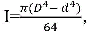 and
and
where E = elastic modulus, and I = second moment of area.
One of ordinary skill in the art can determine the bending stiffness of the hollow tube using similar dimensions and parameters as described above, wherein the bending stiffness is in the range of about 200N/m to 2000N/m. For example, the combined stiffness of the probes may be determined from the stiffness of the components described herein.
In some embodiments, the sheath 742 comprises a stiffness to increase rigidity and stabilize the energy source 250 by movement of the elongate shaft 730 and movement of the energy source relative to the sheath. In some embodiments, ridge 750 is coupled to the sheath to increase the stiffness of the probe. In some embodiments, ridge 750 extends distally beyond energy source 250. The spine may comprise a tube comprising one or more of a fluid supply channel or a fluid removal channel coupled to one or more openings 932 remote from the energy source to provide fluid or remove matter generated by the energy source. In some embodiments, the ridge includes a first side including a concave surface facing and spaced apart from the energy source and a second side including a convex surface facing away from the energy source to engage tissue. In some embodiments, the ridge extends beyond the distal end of the sheath, and the one or more openings are located distally beyond the distal end of the sheath. The ridge may extend to a distal tip 760, where the distal tip includes a rounded end for insertion of a probe and a groove 940 in the tip to allow fluid to pass around the tip when the tip engages the walls of the lumen.
Although a rigid sheath is mentioned, in some embodiments, the sheath comprises a flexible sheath.
The processing probe 700 may be configured to receive another energy source as shown in fig. 9. In some embodiments, the first energy source 250 is configured to be offset from the elongate axis of the probe and the second energy source 200 is configured to direct energy outward, e.g., emit energy radially outward away from the axis 451, or emit energy along the axis 451, e.g., with an end-firing configuration.
The processing probe 700 can be configured in a variety of ways. In some embodiments, although the ridge 750 may be flexible, the treatment probe may include a rigid ridge 750 to maintain placement of the probe. In some embodiments, the probe 700 includes one or more joints to move the energy source away from the elongate axis 451 of the probe, e.g., through articulation of the one or more joints.
The probe 700 may include a fluid supply channel 920 coupled to one or more openings 922 and a fluid removal channel 930 coupled to the one or more openings. The probe 700 may include one or more openings 932 for removing (e.g., suctioning) tissue products, such as tissue resection products, and one or more openings 922 for supplying fluid to the energy delivery area. The opening may remain substantially stationary as the energy source 250 is moved. In some embodiments, linkage 710 comprises an articulation joint coupled to energy source 250 having an extension 720. In some embodiments, energy source 250 comprises a ring electrode. Articulation of the joint may provide displacement of the energy source at a controlled deflection angle, which may provide improved accuracy of tissue, treatment, resection, and cauterization.
In some embodiments, rotation of the extension 720 relative to the pivot at the link 710 and translation and rotation of the shaft 730 about the elongate axis 451 can provide three-dimensional (3D) volumetric ablation of tissue with the probe.
Fig. 8 and 9 show the treatment probe 700 of fig. 7, wherein a second treatment probe 950 comprising a second energy source 200 (e.g., a waterjet device) has been placed in the treatment probe 700. In some embodiments, the second treatment probe 950 is placed in the treatment probe 700 after one or more components of the treatment probe 700 have been placed in the patient. In some embodiments, the first energy source (e.g., laser or electrode) is configured to rotate, translate, and offset, e.g., pivot, and the second energy source is configured to translate and rotate such that the energy sources are controlled in 5 or more degrees of freedom, e.g., according to a motor on the end of a robotic arm as described herein.
Fig. 10 and 11 show the inner and outer structures of the probe as in fig. 7 to 9. Figure 10 shows a cross-sectional view of the probe of figures 7 to 9. Figure 11 shows a perspective view of the internal drive structure of the probe of figures 7 to 10. In some embodiments, the stylet includes an outer sheath 742 of a suitable diameter, such as a 24French ("FR") sheath (24 French "). In some embodiments, a fluid removal channel 930 (e.g., suction channel) and a fluid supply channel 920 (e.g., irrigation channel) are located within the sheath 742 and extend at least partially around the components of the shaft 730. In some embodiments, shaft 730 includes an articulation drive tube 732 for energy source deflection and a rotation and translation drive tube 734, such as an RF loop drive tube. One or more of the articulation drive tube 732 or the rotation and translation drive tube 734 may be sized and shaped to receive a second treatment probe 950, such as a water jet probe, as described herein. The endoscope 910 may include a CMOS camera sensor, one or more lenses, and an LED light source. While the endoscope 910 can be located at any suitable location in the probe, in some embodiments the endoscope 910 is located near the end of the drive tube and is fixed relative to the sheath to view the energy source and the extension 720 as the extension 720 moves the energy source. Alternatively, endoscope 910 may be positioned on extension 720 to place the endoscope in close proximity to, for example, tissue being treated with an energy source.
The diameter of the outer sheath may be sized in any suitable unit, such as a diameter in millimeters ("mm"), or with the French scale. The dimensions of the French scale can be easily converted to a diameter in mm, which is about 1/3 of the French size. Thus, as known to those of ordinary skill in the art, a 24FR sheath will have a diameter of about 8 mm.
In some embodiments, fluid supply channel 920 and fluid removal channel 930 are located within sheath 742 to provide improved engagement and rotational stability. In some embodiments, the fluid supply channel 920 includes one or more insufflation or irrigation channels, and the fluid removal channel 930 includes one or more drainage or aspiration channels.
In some embodiments, the fluid supply channel 920 and the fluid removal channel 930 are sized and shaped to engage each other within the sheath 742, wherein one or more of the fluid supply channel 920 or the fluid removal channel 930 are sized and shaped to receive the elongate shaft 730 coupled to the energy source 250 to allow rotation and translation of the energy source 250. In some embodiments, the fluid supply channel 920 is sized and shaped to receive the elongate shaft 730 to provide a supply of fluid along the fluid supply channel to a surgical site with the elongate shaft 730 placed within the fluid supply channel 920. In some embodiments, the removal channel 930 is sized and shaped to receive the elongate shaft 730 to remove fluid from the surgical site along the fluid removal channel 930 with the elongate shaft 730 placed within the fluid removal channel.
The shaft 730 may be configured in a variety of ways to deflect, rotate, and translate the energy source 250. In some embodiments, the elongate shaft 730 includes a first elongate drive tube 732 to offset the energy source 250 relative to the elongate axis 451, such as to offset the extension 720 from the elongate axis 451. In some embodiments, elongate shaft 730 includes a second elongate drive tube 734 to rotate and translate energy source 250 in the event the energy source is offset relative to elongate axis 451, for example, by deflection of extension 720 away from the elongate axis.
The first elongated drive tube 732 and the second elongated drive tube 734 may be configured in a variety of ways to move the energy source 250. In some embodiments, first elongate drive tube 732 and second elongate drive tube 734 are configured to rotate and translate together to move energy source 250 in rotation and translation if the energy source is offset relative to axis 451, such as by deflection of the extensions relative to the elongate axis. Alternatively or in combination, first elongate drive tube 732 and second elongate drive tube 734 are configured to rotate and translate independently to cause rotational and translational movement of energy source 250. In some embodiments, the first elongated drive tube 732 and the second elongated drive tube 734 are arranged in a side-by-side configuration (not shown). In some embodiments, the first elongated drive tube 732 and the second elongated drive tube 734 are arranged one above the other. For example, the first elongated drive tube and the second elongated drive tube may be arranged in a coaxial configuration.
In some embodiments, the drive tube is sized to receive a second probe 950 comprising a second energy source. First drive tube 732 and second drive tube 734 are sized to receive a second probe 950, second probe 950 including a third drive tube 952, third drive tube 952 being coupled to a second energy source for rotating and translating the second energy source relative to one or more of first drive tube 732, second drive tube 734, or sheath 742.
The first energy source 250 may comprise any suitable energy source, and may include, for example, one or more of the following: an electrode, a ring electrode, a monopolar electrode, a bipolar electrode, a radio frequency source, a microwave source, a plasma source, a heat source, a laser source, a mechanical energy source, a mechanical cutter source, a vibrational energy source, an ultrasonic energy source, a cavitation ultrasound source, a water jet device, a fixed pressure water jet device, a variable pressure water jet device, a water jet evacuation source, a vapor source, a morcellator, a light ablation energy source, an ionizing radiation energy source, a radioisotope, an ionizing plasma source, or a cryogenic energy source.
Although reference is made to a second energy source comprising the nozzle 200, the second energy source may comprise any suitable energy source as described herein, and may include, for example, one or more of the following: an electrode, a ring electrode, a monopolar electrode, a bipolar electrode, a radio frequency source, a microwave source, a plasma source, a heat source, a laser source, a mechanical energy source, a mechanical shears source, a vibrational energy source, an ultrasonic energy source, a cavitation ultrasound source, a water jet device, a fixed pressure water jet device, a variable pressure water jet device, a water jet evacuation source, a steam source, a shredder, a photoablation energy source, an ionizing radiation energy source, a radioisotope, an ionizing plasma source, or a cryogenic energy source.
In some embodiments, the second energy source 250 comprises a water jet device as described herein. In some embodiments, a third elongated drive tube 952 is coupled to the nozzle to generate the water jet. In some embodiments, a third elongate drive tube 952 extends proximally from the nozzles in the first and second drive tubes to rotate and translate the waterjet device relative to the first and second drive tubes.
Fig. 12A and 12B show top and side views, respectively, of a probe 700, the probe 700 including a variable offset energy source 250 configured for manual use with a handle 1200. In some embodiments, the probe includes a manual control for pivoting the energy source in response to movement of the manual control as described herein. The elongate shaft 730 extends proximally toward the handle 1200 to control the angle of rotation of the energy source about the elongate axis. In some embodiments, the shaft 730 is coupled to the handle to rotate the energy source as the handle is rotated. The shaft 730 may include a coupling extending proximally toward the handle to control the offset distance of the energy source relative to the elongate axis 451. In some embodiments, the coupling device includes a knob 1230 to control the deflection 254 and corresponding offset distance as the knob is rotated 1232. The handle 1200 can include a slider 1220 to move the energy source in translation 418 along the elongate axis 451 by corresponding proximal and distal movement of the slider 1220. Alternatively, the linkage may be configured to control the offset distance using rotational movement 1232 of the slider 1220 and knob 1230.
In some embodiments, a rigid sheath 742 extends from the handle 1200 to an opening proximal of the link 710 to increase rigidity. The shaft 730 may be configured to move within a rigid sheath to translate the energy source 250. A coupling device including a shaft 730 extends between the coupling and the handle to bias the energy source relative to the elongate shaft in response to rotation of the knob. In some embodiments, the handle 1200, the shaft 730, and the rigid sheath 742 are configured to move together to rotate the energy source 250 in rotation about the elongate axis 451 via the rotation 453.
While the controls of the handle can be configured in a number of ways, in some embodiments, the finger engagement structure 1210 is configured to engage a finger of a user, and the slider 1220 includes a thumb engagement structure that engages a thumb of the user. The thumb engaging structure is coupled to the shaft to translate the energy source as the thumb engaging structure translates relative to the shaft.
The extension 720 may include a fluid supply channel 920 or a fluid removal channel 930 that extends to one or more openings supported by the extension. In some embodiments, the one or more openings are configured to move toward and away from elongate shaft 451 as energy source 250 is deflected and straightened by coupling 710.
Although manual articulation has been mentioned, movement of the energy source may be performed under computer control, for example in conjunction with a handpiece as described herein, through one or more linkages.
Fig. 13A-13C show cross-sectional views of probes that include asymmetric internal structures to provide rotational stability.
Fig. 13A shows a probe 700, the probe 700 including a sheath 740, a fluid supply channel 920, and a fluid removal channel 930. The fluid supply channel 920 includes a tube 924, and the fluid removal channel 930 includes a tube 934, wherein the tube 924 and the tube 934 are configured to engage one another. The tube may include an interlocking structure 1320, the interlocking structure 1320 including a plurality of protrusions 1322 and a plurality of recesses 1324 that engage one another in an interlocking configuration. In some embodiments, a compression element 1310, such as a spring, is configured to urge the tube and the interlock structure toward each other to increase stability. Interlocking structures may extend along the probe to increase rotational and translational stability.
Fig. 13B shows a probe 700, the probe 700 including a sheath 740, a fluid supply channel 920, and a fluid removal channel 930. The fluid supply channel 920 includes a tube 924, and the fluid removal channel 930 includes a tube 934, wherein the tube 924 and the tube 934 are configured to engage one another. As described herein, one or more tubes are configured to receive a treatment probe. The tube 924 includes an engagement structure 1010, the engagement structure 1010 configured to engage a corresponding engagement structure 1020 on the tube 934 to provide rotational stability. The tubes may include additional engagement structures, such as grooves 1030 on the tubes 934, the grooves 1030 being shaped to engage projections 1035 on the tubes 924 to provide translational stability when the tubes are engaged with one another. The engagement surface of the tube may include additional structure, such as surface roughening to provide friction between the probes.
Fig. 13C shows probe 700, probe 700 including sheath 740, fluid supply channel 920, and fluid removal channel 930. The fluid supply channel 920 includes a tube 924, and the fluid removal channel 930 includes a tube 934, wherein the tube 924 and the tube 934 are configured to engage one another. As described herein, one or more tubes are configured to receive a treatment probe.
In some embodiments, one or more elements include an asymmetric shape such that the elements of the assembly contribute to the torque transfer capability. In some embodiments, the axially extending element comprises an engagement structure, such as an interlocking structure. In some embodiments, the structure may be actuated by one or more of a screw function or a pull/push function. In some embodiments, the probe elements are configured to interact, for example, at one or more of a proximal location, a distal location, or along the assembly.
In some embodiments, the components include mating shapes between the individual pieces, such as a single or multiple mating protrusions or ramps, and/or 3-D interlocking features that prevent expansion of the system, wherein movement between them results in locking.
In some embodiments, the working element comprises sufficient rigidity to accurately perform the movement, with reduced hysteresis.
In some embodiments, one or more components include a cylindrical geometry, such as an annular geometry, to engage a cylindrical wall of another component and utilize the available wall thickness.
In some embodiments, the outer shaft of surgical probe 700 provides rigidity from bending to ensuring precise movement and positioning within the surgical space. The outer shaft may also protect the internal components from bending while allowing them to perform their functions of rotational, translational (e.g., piston), and offset actuation.
In some embodiments, the components of the probe include reversible interlocking structures that associate (bind) the various elements with one another to create a round torque cylinder (round torque cylinder) in which the internal elements are coupled together within a sheath. In some embodiments, the cross-sectional profile of the probe elements enhances torque transmission of the internal assembly as the probe elements engage one another. Which are examples of several of the many different geometric interlocking configurations that may be used in accordance with the present disclosure.
Although a two-dimensional cross-sectional view is shown, in some embodiments, the probe elements include three-dimensional geometric interlocking features, such that relative axial movement of the elements may be reduced.
Fig. 14A and 14B show a push-pull configuration for biasing the energy source.
In some embodiments, the tube within the tube includes a push/pull configuration that results in an angled bend (angle bend) or other action. The coupling means may be configured in a variety of ways and may include, for example, one or more of a nut drive or a pull wire. In some embodiments, the push/pull wire assembly is configured to provide angular deflection. For example, the coupling means may suitably comprise a slot and a pin.
In some embodiments, the push/pull coaxial tube drive shaft 1412 may be a threaded rod threadedly coupled to the proximal end of the extension 720 that rotates to deflect the extension 720 and displace the energy source 250. In some embodiments, the coupling device includes an anti-backlash feature, for example, a spring-loaded nut with threads in both directions of actuation.
As described herein, the coupling device may extend proximally to the coupler and the control.
Fig. 14A shows a probe comprising a rotational coupling 1410. The coupling device 1410 may include a threaded female structure 1416 similar to a nut and a threaded drive shaft 1412. The threaded female formation 1416 is shaped to receive the threaded rod 1412. As the rod 1412 rotates 1420, the extension 720 moves toward or away from the elongated axis depending on the direction of rotation. The link 710 is coupled to a threaded structure to pivot the extension 720 about the link 710 and provide the deflection 254.
Figure 14B shows a stylet including a push-pull coupling 1450. As described herein, to move the energy source through the deflection 254 of the extension. For example, the coupling 710 may include a pin 1460. The coupling device may include additional pins 1462, 1464, the additional pins 1462, 1464 being coupled to additional extensions extending proximally from the extension 720. The translational movement 1470 moves the energy source toward and away from the elongate axis. In some embodiments, distal movement 1472 offsets extension 720 from the elongate probe axis and proximal movement 1474 moves extension 720 toward the elongate axis.
Fig. 15A-15D show a surface follower positioning an energy source relative to depth from a tissue surface contour.
While these figures show electrocautery wires as the energy source, any suitable energy source may be used as described herein. In some embodiments, the surface follower is configured to slide along the surface of the tissue while the energy source extends into the tissue to one or more of a single set depth or a user adjustable depth to reach the treatment depth.
Fig. 15A and 15B illustrate the energy source coupling element pivoting about an axis, wherein angular displacement relative to the follower provides greater resection depth.
Fig. 15A shows a follower 1510 coupled to the extension 720 and the energy source 250 to engage and follow a tissue surface 1500. The follower allows the energy source to ablate tissue at a depth from the tissue surface as the follower is moved in direction 1504 by the extension 720. An elongate member 1505 extends between the follower 1510 and the energy source to control the depth of tissue ablation 1502. Member 1505 may include a substantially fixed length between follower 1510 and energy source 250. Alternatively, member 1505 may include a variable length to vary the depth of tissue resection from tissue surface 1500.
In some embodiments, the energy source 250 is coupled to the follower 1510 to change one or more of a distance or angle between the follower and the energy source to ablate tissue to the depth 1502.
As shown in fig. 15A, follower 1510 is configured with a pivot 1520. The angle between the follower and the elongate member 1505 corresponds to the amount of deflection of the extension relative to the elongate probe axis. Increasing the deflection of the extension 720 increases the angle between the follower and the energy source and the corresponding ablation depth from the tissue surface.
Fig. 15B shows a follower 1510 coupled to an energy source 250, wherein the elongate member is configured to change the ablation depth to a plurality of depths 1502A, 1502B, and 1502C. Tissue can be cut to depth by varying one or more of the distance or change in angle relative to the elongated surface profile of follower 1510. The elongated surface profile of the follower is shown engaging tissue 1500. The extension 720 may include one or more of a wire, shaft, lever, extension, rod, or coupling device that extends along the extension to vary one or more of a distance or angle to vary the resection depth from the tissue surface profile.
As shown in fig. 15B, the follower 1510 is configured to pivot the member 1505 with respect to the follower 1510 and the extension 720 to change the distance to a plurality of distances 1502A, 1502B, 1502C.
While ablation may be performed in many ways, in some embodiments, the angle between the follower and the energy source is adjusted to change the ablation distance between the slider and the energy source while the amount of deflection of the extension remains substantially fixed.
Fig. 15C shows a follower 1510 coupled to an extension 720 by a spring 1540. The follower is configured to slide along the extension 720. Spring 1540 allows follower 1510 to provide a variable force to tissue surface 1500. In some embodiments, the spring 1540 includes a force limiting feature such that the processing element can change depth based on the reaction force during execution.
Fig. 15D shows a follower coupled to an energy source through a deflectable member 1550, such as a spring, e.g., a leaf spring. Member 1550 is configured to decrease in depth in response to increased tissue resistance of the tissue and increase in depth in response to decreased tissue resistance. As shown in fig. 15D, the preformed wire or spring element is configured to control the positioning of the treatment element, where the length of the spring element affects the depth of ablation from the follower 1510.
Fig. 16A-16C show an energy source 250 coupled to a surface follower 1510 having a pivot 1530, where the pivot 1530 is near the surface of the tissue follower. The extension 720 includes one or more push-pull extensions 1610 coupled to the energy source 250. One or more wires 1610 extend from the extension 720 within one or more tubes 1630 to pivot the energy source 250 relative to the tissue follower 1510 about a pivot axis 1531 along a path 1532. Translational movement 1620 of the wire 1610 within the extension 720 may be used to adjust the pivot angle. The pivot angle can be adjusted to resect tissue to a first depth 1502A as shown in fig. 16B or a second depth 1502B as shown in fig. 16C.
Fig. 17A-17C show the energy source 250 coupled to the surface follower 1510, with the energy source 250 extending to a variable depth from the follower 1510 to the tissue. The variable extension depth may be controlled with one or more push-pull extensions 1610 (e.g., wires, tubes, or shafts) that may be used to vary the depth. In some embodiments, retraction of the extension 1610 between the follower and the energy source reduces the distance to a first distance 1502A, and advancement of the extension 1610 increases the distance to a second distance 1502B.
The coupling 710 may be configured in a variety of ways to offset the energy source 250 relative to the elongate axis 451. In some embodiments, for example, the coupling comprises one or more of: a pivot, a hinge, a bendable link, a plurality of slits in a tube, or a plurality of non-planar slits in a tube.
Fig. 18A illustrates deflection of a linkage 710 including a bendable linkage to deflect an energy source with complementary structures (e.g., interlocking structures) to provide rotational stability. Figure 18B shows a cross-sectional view of the probe shown in figure 18A. Fig. 18C shows a bottom view of the probe of fig. 18A-18B. Fig. 18D shows deflection of the probe of fig. 18A-18C, wherein the deflection angle relative to the elongate axis of the probe is greater than 45 degrees.
The bendable link may be configured in a variety of ways and may have an internally actuated tensioning or expansion feature to increase the rigidity of the distal end. In some embodiments, the slit interlocking elements interlock in three dimensions, e.g., radially, and have, e.g., wedge-shaped features. In some embodiments, for example, the slit is made by laser cutting the tubing at a laser angle to create a tapered shape, with a male taper fitting into a female taper. In some embodiments, the cut tubing includes interlocking slits to improve rotational stability.
In some embodiments, the deflection angle 254 can be controlled by the distance of the link elements that extend beyond the distal opening 1850 of the sheath 740. For example, the rotational and translational positioning of the linkage 710 may be controlled by the shaft 730. In some embodiments, linkage 710 includes a plurality of slits 1800 that define a plurality of gaps 1810. One or more of the plurality of distances across the plurality of gaps 1810 is configured to decrease to deflect the extension 720 and move the energy source 250 away from the elongate axis. A plurality of slits 1800 extend through the first side of the tube and only partially through the second side of the tube to allow the tube to bend along the second side while reducing a plurality of distances along the first side. In some embodiments, plurality of slits 1800 is configured to close at least partially along one or more of the plurality of slits to deflect the extension and move the energy source away from the axis. In some embodiments, the deflection angle is related to the number of closed slits 1820.
The slits may be configured to provide improved stiffness and torsional deflection by suitable structure. In some embodiments, the plurality of slits includes a non-planar slit 1860, such as a V-shaped slit. The non-planar slits include corresponding opposing engagement structures to engage one another with at least a portion of the plurality of slits closed.
In some embodiments, the sheath 740 includes a retaining sheath over the plurality of slits to control the angle of deflection of the extension by uncovering one or more of the plurality of slits from the sheath. The deflection angle 254 is related to the number of slits uncovered from the sheath and the distance one or more of the plurality of slits extends beyond the distal end 1850 of the sheath. As shown in fig. 18A-18D, the deflection angle 254 may gradually increase as the slit is uncovered, as shown by deflections 254A, 254B, and 254C, respectively.
In some embodiments, a linkage is coupled to one or more of the sheath or plurality of slits to move one or more of the slits or shafts and expose and cover the plurality of slits with the shafts to control the deflection angle. The coupling means may comprise any suitable coupling means as described herein, and may comprise, for example, one or more of the following: a screw linkage, a preloaded spring, a pull wire, a gear, or a rod coupled to the proximal portion of the probe.
The sheath may be configured in any suitable manner to keep the gap open while remaining within the sheath 740. In some embodiments, the sheath 740 includes sufficient stiffness to move the extension and the energy source toward the elongate shaft after the extension has deflected away from the elongate shaft. In some embodiments, the sheath includes sufficient stiffness to open one or more of the plurality of gaps after the distance across the one or more of the plurality of gaps is reduced to move the energy source and the extension toward the elongate shaft.
FIGS. 19A and 19B show side and top views, respectively, of a probe having an energy source, such as an electrocautery wire cutter, extending at an oblique angle to the bending element. In some embodiments, the cutting edge of the electrode is at an oblique angle, e.g., 45 °, to the axis to allow cutting action to occur in direction 1950 with rotational movement 1954 and translational movement 1952 (e.g., axial movement). In some embodiments, the oblique angle increases the rate of tissue axial and rotational movement, such as when the direction of movement of the electrode is substantially perpendicular to the tissue receiving area of the electrode.
As shown in fig. 19B, the deflection 254 of the extension 720 and the electrode away from the shaft may be aligned with the elongated shaft such that the deflection 254 remains aligned with the elongated shaft, which may improve rotational accuracy and reduce errors associated with eccentric movement of the energy source 250.
The energy source 250 may include an electrode shaped to define a region 1920 through which the ablated tissue may pass when the electrode ablates tissue by movement of the electrode. In some embodiments, the region 1920 defined by the electrodes extends in a direction 1956 oblique to the elongate axis 451 of the shaft and in a plane perpendicular to the elongate axis of the shaft.
Although the region 1920 can be configured in many ways, in some embodiments, the region comprises an area defined by the non-linear shape of the cutting edge 1910 of the electrode. The area defined by the rim 1910 extends in a direction 1956 oblique to the elongate axis of the shaft and a plane 1957 perpendicular to the elongate axis 451. The non-linear shape may include a portion of a loop, such that the portion of the loop defines an area of zone 1920. In other words, the region is defined by the curved electrode, and wherein the curved electrode extends in a direction oblique to the elongate axis of the shaft and in a plane perpendicular to the elongate axis.
While the oblique angle can be configured in many ways, in some embodiments, the direction 1956 extends at an angle in a range of about 15 degrees to about 75 degrees, and also optionally in a range of about 30 degrees to about 60 degrees, from the elongate axis 451 and the plane 1957.
As described herein, the tilted configuration of the electrodes is well suited for processor-controlled tissue shaping (tissue scraping) with rotational and translational movement. The processor is operably coupled to a coupling device including a shaft to rotate and translate the electrode with the extension offset from the elongate axis. The processor may be configured with instructions to offset the electrode relative to the elongate axis and rotate and translate the shaft to move the electrode via rotational movement 1954 and translational movement 1952 to pass tissue through a zone 1920 defined by the non-linear shape of the cutting edge 1910 of the electrode. In some embodiments, the cutting edge 1910 of the electrode extends in direction 1956, and the processor is configured with instructions to move the electrode transverse to the direction along which the cutting edge extends in order to facilitate movement of excised tissue through zone 1920. In some embodiments, the processor is configured to reduce (e.g., limit) movement of the electrode in a direction 1956 along which the cutting edge extends.
While the probe may be configured to move the electrodes in a number of ways, in some embodiments the direction of movement of the electrodes corresponds to the simultaneous rotational movement 1954 and translational movement 1052 of the electrodes.
Fig. 20A and 20B illustrate an energy source 250, the energy source 250 comprising a mechanical energy source, such as a cutting element. In some embodiments, the energy source comprises a mechanical cutting shears for cutting tissue. The cutting element includes a moving cutting edge and a moving cutting edge 2030.
Fig. 20A shows a fixed outer tube having a cutting edge 2020 on one or both surfaces (distal, proximal, or both) that interacts with a reciprocating inner element 2010 that includes an edge 2012 for shearing tissue. The inner element 2010 may include a tubular central region from which sheared tissue is removed. For example, the inner element 2010 is moved back and forth in a single physician-controlled motion or by a motorized reciprocating motion. In some embodiments, for example, the central lumen of the assembly may be used under vacuum suction to remove the severed tissue.
Although reference is made to movement of the inner element while the outer element is fixed, the movement may be reversed.
Fig. 20B shows tissue shearing with rotational motion. The inner element 2010 includes a cutting edge 2012. The stationary element includes a rim 2020. The stationary element may comprise a honeycomb end of the outer tube. The inner element can include a close-fitting central tube that rotates or reciprocates 2050 to provide tissue resection.
In some embodiments, the outer tube has a partially closed end defining one or more openings to receive tissue, and the internal rotating cutting element shears tissue drawn into the one or more openings. A suction element, such as a tube, may be configured to suction tissue into the one or more openings to cut the tissue when engaged with the inner rotating element.
The stationary element may include a stabilizing structure for receiving tissue and a cutting edge that engages the tissue against the stabilizing structure to resect the tissue by shearing when engaged with the edge 2012 of the moving element. The cutting edge may be moved in one or more of a translational or rotational motion to shear tissue. The tissue stabilizing structure includes a recess or aperture 2060 for receiving tissue 2070.
In some embodiments, the mechanical energy source comprises one or more elements of a vitrectomy device (vitrector) that are well known to those or ordinary skill in the art of ophthalmic surgery.
As described herein, the mechanical energy source 250 may be powered by one or more elongated structures extending along the extension 720 to transmit energy to the energy source 250 when the extension is off-axis.
Fig. 21A-21F illustrate a variable-deflection energy source 250, the variable-deflection energy source 250 including a variable-deflection waterjet device coupled to a variable-deflection evacuation cavity. These embodiments show a jet chamber where the jet enters a receiving or evacuation chamber which together form a jet pump, creating a partial vacuum capable of drawing loose tissue into the jet zone, allowing jet power to act on the tissue, cutting and ablating the tissue as it is driven along the evacuation chamber and out of the surgical space.
These configurations can provide tissue ablation by drawing tissue into a water jet device using entrainment (entrainment). The tissue to be aspirated with entrainment may include any suitable tissue, such as naturally occurring tissue, or collagen fibers after tissue resection with a water jet.
In some embodiments, one of the lumens includes an electrically exposed surface to cauterize tissue to promote hemostasis and tissue ablation.
Fig. 21A and 21B show a probe 700 that includes a variable offset energy source 250. The probe 700 may include one or more components of the probe 450 as described herein. The probe 700 may include components described herein, such as a coupling 710, an extension 720, a shaft 730, a ridge 750, and a tip 760. As described herein, the coupling 710 may be configured to deflect the energy source 250 as the extension 720 deflects 254. The extension 720 includes a water jet supply tube 2110 coupled to a nozzle 2150 of the water jet device and a fluid removal channel 2120. The fluid removal channel 2120 extends to an opening 2122 to remove matter generated by an energy source, such as a water jet device 2140. The waterjet device 2140 is directed towards the opening 2122. A nozzle is coupled to the jet supply tube 2110 to generate a water jet device 2140. The nozzle 2150 of the waterjet device 2140 is oriented in a direction towards the opening 2122, thereby directing the resected tissue towards the opening. In other words, nozzle 2150 faces opening 2122.
In some embodiments, nozzle 2150 and opening 2122 are separated by a gap 2130 that defines a distance 2132 between the nozzle and the opening. The gap 2130 is sized to entrain tissue to the waterjet device 2140 for ablation. In some embodiments, opening 2122, nozzle 2150, and gap 2130 are arranged in a jet pump configuration to draw tissue into the gap. The distance may include any suitable distance and may range from about 0.1mm to about 5mm, and optionally, for example, from about 0.25mm to about 2.5 mm.
In some embodiments, extension 720 includes a jet supply tube 2110 and an evacuation tube 2120. As described herein, evacuation tube 2120 including a fluid removal channel, as well as the jet supply tube and evacuation tube, are configured to move gap 2130 as extensions 703 are moved together with deflection.
In some embodiments, jet supply tube 2110 and evacuation tube 2120 are arranged in a side-by-side configuration. For example, the jet supply tube and the evacuation tube may be arranged in an over under configuration.
As shown in fig. 21A, the nozzle is oriented toward the opening in a direction transverse to the elongated axis 451, and the opening 2122 is oriented in a direction transverse to the elongated axis. In some embodiments, the nozzle and the opening are oriented substantially perpendicular to the elongated axis. With these lateral configurations, the gap 2130 is placed proximate to the tissue 2100 to facilitate removal of the tissue. Work in relation to the present configuration suggests that other configurations may be helpful depending on the type of tissue being removed.
In some embodiments, for example, the water jet supply tube 2110 and the evacuation tube 2120 are arranged in a side-by-side configuration relative to the elongate axis 451, which may facilitate pivoting at the coupling 710.
Fig. 21C and 21D show a nozzle oriented toward the opening in a direction toward the elongate axis 451 and an opening 2122 oriented away from the probe and the elongate axis near the tip 760 of the probe 700. In some embodiments, for example, the water jet supply tube 2110 and the evacuation tube 2120 are arranged in a top-bottom configuration relative to the elongate axis 451. For example, the water jet supply pipe 2110 can be located below the evacuation pipe 2120.
Fig. 21E and 21F show the nozzle oriented in a direction away from the probe and elongate axis 451 and the opening 2122 oriented toward the elongate axis 451 near the tip 760. The water jet supply tube 2110 and the evacuation tube 2120 are arranged in an up-down configuration relative to the elongate axis 451. The water jet supply pipe 2110 is located above the evacuation pipe 2120.
Fig. 22A-22C show a probe 700, the probe 700 including a variable-deflection waterjet apparatus and an evacuation cavity in a counter-current waterjet configuration. As shown, probe 700 includes components and movements similar to the probe shown in fig. 21E-21F.
With these counter-current water jet configurations, the water jet device is directed toward the coupling 710 and the axis 451. As shown in fig. 22A, the jet supply conduit 2110 and evacuation conduit are arranged in a side-by-side configuration relative to the elongate axis 451. The waterjet device 2140 is oriented toward the elongated axis of the elongated evacuation tube 2120, which can facilitate aspiration of tissue and fluid with entrainment.
Fig. 22C shows the jet supply conduit 2110 and the evacuation conduit arranged in an up-down configuration relative to the elongate axis 451. The water jet supply tube 2110 is shown above the evacuation tube 2120. The waterjet device 2140 is oriented toward the elongate axis of the elongate evacuation tube 2120 to facilitate aspiration of tissue and fluid with entrainment.
Fig. 23 shows a method 2300 of treating a patient.
At step 2310, the processor receives user input, such as a processing profile or movement command from a user control coupled to a linkage device described herein.
At step 2320, the processor receives an input corresponding to the shape of an energy source (such as an electrode). The processor may be configured to rotate and translate the electrode with the extension offset from the elongate axis. In some embodiments, a processor is configured with instructions to: the elongate shaft is rotated and translated to move the electrodes and pass tissue through a zone defined by the electrodes.
At step 2330, the processor determines a direction of movement to facilitate advancement of tissue through a region of an energy source (such as an electrode). In some embodiments, the cutting edge of the electrode extends in one direction, and the processor is configured with instructions to: the electrode is moved transversely to the direction along which the cutting edge extends to facilitate movement of the resected tissue through the region. In some embodiments, the processor is configured with instructions for limiting movement of the electrode in a direction along which the cutting edge extends.
At step 2340, the processor determines that the movement of the electrode corresponds to synchronous offset, rotational and translational movement of the energy source (such as the electrode). For example, as described herein, the processor may be configured to cause the electrodes to move simultaneously with one or more of: offset, rotate about, or translate along the elongate axis.
At step 2350, the processor receives as input a tissue ablation profile. In some embodiments, the processor is configured to determine a plurality of offsets of the energy source corresponding to the tissue ablation profile.
The tissue resection profile may correspond to a three-dimensional tissue resection profile, and the processor is configured with instructions to: a plurality of offsets, translations, and rotations of the energy source about the elongate axis are determined to position the energy source at a plurality of locations corresponding to a three-dimensional tissue ablation profile. An example of a suitable three-dimensional TISSUE ablation profile is described in PCT/US2014/054412 entitled "AUTOMATED IMAGE-GUIDED TISSUE preservation AND procedure" filed on 5.9.2014, which PCT/US2014/054412 is published as WO 2015/035249, the entire disclosure of which has been previously incorporated herein by reference.
At step 2360, the processor determines a plurality of positions of the tissue ablation profile relative to the elongate axis of the probe.
At step 2370, the processor determines a plurality of corresponding offsets, rotations, and translations of the energy source relative to the elongate axis. The processor determines, for each of a plurality of positions of the tissue ablation profile, a corresponding offset, a corresponding rotation, and a corresponding translational position of the energy source relative to the elongate axis. In some embodiments, the offset comprises a deflection of the energy source away from the elongate axis of the probe, and wherein the processor is configured with instructions to: translation of a shaft coupled to the energy source is determined in response to the deflection angle of the energy source and the translational position of the three-dimensional profile relative to the elongate axis.
At step 2380, the processor adjusts an amount of energy from the energy source in response to a magnitude of the impedance of the energy source.
At step 2385, the processor adjusts the offset of the energy source relative to the elongate axis in response to the magnitude of the impedance. In some embodiments, a processor is configured with instructions to: the amount of deflection of the extension and the offset of the energy source relative to the elongate axis are adjusted in response to the magnitude of the impedance.
At step 2390, the processor adjusts the offset of the energy source relative to the elongate axis in response to the magnitude of the force measured with the force sensor.
At step 2395, the processor adjusts the amount of energy from the energy source in response to the magnitude of the force measured with the force sensor.
Although fig. 23 illustrates a method of treating a patient according to some embodiments, one of ordinary skill in the art will recognize many adaptations and variations. For example, the steps may be performed in any suitable order. Some steps may be omitted and some steps may be repeated. Further, some steps may include sub-steps of other steps. Further, a computing device such as a processor as described herein may be configured to perform one or more steps of method 2300.
As described herein, the computing devices and systems described and/or illustrated herein broadly represent any type or form of computing device or system capable of executing computer-readable instructions (e.g., those contained within modules described herein). In their most basic configuration, these computing devices may each include at least one memory device and at least one physical processor.
The term "memory" or "memory device" as used herein generally represents any type or form of volatile or non-volatile storage device or medium capable of storing data and/or computer-readable instructions. In one example, a memory device may store, load, and/or maintain one or more modules described herein. Examples of memory devices include, without limitation, random Access Memory (RAM), read Only Memory (ROM), flash memory, a Hard Disk Drive (HDD), a Solid State Drive (SSD), an optical disk drive, a cache, variations or combinations of one or more of them, or any other suitable memory.
Furthermore, the term "processor" or "physical processor" as used herein generally refers to any type or form of hardware-implemented processing unit capable of interpreting and/or executing computer-readable instructions. In one example, a physical processor may access and/or modify one or more modules stored in the memory device described above. Examples of physical processors include, without limitation, a microprocessor, a microcontroller, a Central Processing Unit (CPU), a Field Programmable Gate Array (FPGA) implementing a soft-core processor, an Application Specific Integrated Circuit (ASIC), portions of one or more of them, variations or combinations of one or more of them, or any other suitable physical processor. The processor may comprise a distributed processor system, such as a running parallel processor, or a remote processor, such as a server, and combinations thereof.
Although illustrated as separate elements, the method steps described and/or illustrated herein may represent portions of a single application. Further, in some embodiments, one or more of these steps may represent or correspond to one or more software applications or programs that, when executed by a computing device, may cause the computing device to perform one or more tasks, such as method steps.
Further, one or more devices described herein may convert data, physical devices, and/or representations of physical devices from one form to another. Additionally or alternatively, one or more modules described herein may transform a processor, volatile memory, non-volatile memory, and/or any other portion of a physical computing device from one form of computing device to another form of computing device by executing on the computing device, storing data on the computing device, and/or otherwise interacting with the computing device.
The term "computer-readable medium" as used herein generally refers to any form of device, carrier, or medium capable of storing or carrying computer-readable instructions. Examples of computer readable media include, without limitation, transmission type media (e.g., carrier waves) and non-transitory type media such as magnetic storage media (e.g., hard disk drives, tape drives, and floppy disks), optical storage media (e.g., compact Discs (CDs), digital Video Discs (DVDs), and blu-ray discs), electronic storage media (e.g., solid state drives and flash memory media), and other distribution systems.
One of ordinary skill in the art will recognize that any of the processes or methods disclosed herein can be modified in a variety of ways. The process parameters and the sequence of steps described and/or illustrated herein are given by way of example only and may be varied as desired. For example, although the steps shown and/or described herein may be shown or discussed in a particular order, these steps do not necessarily need to be performed in the order shown or discussed.
The various exemplary methods described and/or illustrated herein may also omit one or more of the steps described or illustrated herein or include additional steps in addition to those disclosed. Further, the steps of any method as disclosed herein may be combined with any one or more steps of any other method as disclosed herein.
A processor as described herein may be configured to perform one or more steps of any of the methods disclosed herein. Alternatively or in combination, the processor may be configured to combine one or more steps of one or more methods as disclosed herein.
Unless otherwise indicated, the terms "connected to" and "coupled to" (and derivatives thereof) as used in the specification and claims are to be construed as allowing both direct and indirect (i.e., via other elements or components). Furthermore, the terms "a" or "an" as used in the specification and claims should be interpreted as at least one of. Finally, for ease of use, the terms "comprising" and "having" (and derivatives thereof) as used in the specification and claims are interchangeable with the word "comprising" and shall have the same meaning as the word "comprising".
A processor as disclosed herein may be configured with instructions to perform any one or more steps of any method as disclosed herein.
It will be understood that although the terms "first", "second", "third", etc. may be used herein to describe various layers, elements, components, regions or sections, these do not relate to any particular order or sequence of events. These terms are only used to distinguish one layer, element, component, region or section from another layer, element, component, region or section. A first layer, element, component, region, or section as described herein may be termed a second layer, element, component, region, or section without departing from the teachings of the present disclosure.
As used herein, the term "or" is used inclusively to refer to alternative and combined items.
As used herein, characters (e.g., numbers) refer to like elements.
The present disclosure includes the following numbered clauses.
Clause 1. A probe for use in treating a subject, comprising:
an energy source;
an elongate shaft comprising an elongate axis;
an extension coupled to the elongate shaft by a coupling to move the energy source away from the elongate axis by movement of the extension away from the elongate axis to offset the energy source relative to the elongate shaft.
The probe of clause 2. The probe of clause 1, wherein the energy source comprises one or more of: an electrode, a ring electrode, a monopolar electrode, a bipolar electrode, a radio frequency source, a microwave source, a plasma source, a heat source, a laser source, a mechanical energy source, a mechanical shear source, a vibrational energy source, an ultrasonic energy source, a cavitation ultrasonic source, a water jet device, a fixed pressure water jet device, a variable pressure water jet device, a water jet evacuation source, a jet pump, a steam source, a shredder, a photoablation energy source, an ionizing radiation energy source, a radioisotope, an ionizing plasma source, or a cryogenic energy source.
Clause 3. The probe of clause 1, further comprising a sheath within which the elongate shaft is positioned to allow the energy source to rotate and translate relative to the sheath with the extension offset from the elongate axis.
Clause 4. The probe of clause 3, further comprising a fluid supply channel and a fluid removal channel within the sheath, and optionally wherein the fluid supply channel comprises one or more of a insufflation channel or an irrigation channel, and the fluid removal channel comprises one or more of a drainage channel or an aspiration channel.
The probe of clause 5. The probe of clause 4, wherein the fluid supply channel and the fluid removal channel are sized and shaped to engage one another within the sheath, one or more of the fluid supply channel or the fluid removal channel sized and shaped to receive the elongate shaft coupled to the energy source to allow rotation and translation of the energy source if the energy source is offset from the elongate axis.
The probe of clause 6. The probe of clause 5, wherein the fluid supply channel is sized and shaped to receive the elongate shaft to provide a supply of fluid to a surgical site along the fluid supply channel with the elongate shaft placed within the fluid supply channel.
The probe of clause 7. The probe of clause 5, wherein the fluid removal channel is sized and shaped to receive the elongate shaft to remove fluid from a surgical site along the fluid removal channel with the elongate shaft placed within the fluid removal channel.
The probe of clause 8. The probe of clause 5, wherein the fluid supply channel comprises a first tube and the fluid removal channel comprises a second tube, and the first tube and the second tube are sized and shaped to engage one another to provide rotational stability when the elongate shaft is rotated and translated.
Clause 9. The probe of clause 8, further comprising a resilient structure coupled to the sheath, the first tube, and the second tube to urge the first tube and the second tube toward each other and provide rotational stability.
The probe of clause 10. The probe of clause 8, wherein the first tube comprises a first portion and the second tube comprises a second portion sized and shaped to engage the first portion in a nested configuration.
The probe of clause 11. The probe of clause 8, wherein the first tube includes a first portion having a first surface profile and the second tube includes a second portion having a second surface profile sized and shaped to engage the first surface profile.
Clause 12. The probe of clause 11, wherein the first and second surface contours include a curved protrusion and a curved groove to engage each other along an axial extent of the curved protrusion and the curved groove.
Clause 13. The probe of clause 11, wherein the first portion and the second portion include a plurality of engaging structures sized and shaped to engage one another.
The probe of clause 16. The probe of clause 11, wherein the first tube comprises a third surface profile sized and shaped to engage the interior of the sheath and the second tube comprises a fourth surface profile sized and shaped to engage the interior of the sheath, and optionally wherein the interior of the sheath comprises a rounded profile and the third surface profile comprises a rounded profile and the fourth surface profile comprises a rounded profile.
The probe of clause 17. The probe of clause 3, wherein the sheath includes a stiffness to increase rigidity and stabilize the energy source with movement of the elongate shaft and movement of the energy source relative to the sheath.
Clause 18. The probe of clause 3, further comprising a ridge coupled to the sheath to increase the stiffness of the probe.
Clause 19. The probe of clause 18, wherein the ridge extends distally beyond the energy source.
The probe of clause 20. The probe of clause 19, wherein the spine comprises a tube comprising one or more of a fluid filling channel or a fluid removing channel coupled to one or more openings distal to the energy source to provide fluid or remove matter produced by the energy source.
The probe of clause 21. The probe of clause 20, wherein the spine includes a first side and a second side, the first side including a concave surface facing and spaced apart from the energy source, the second side including a convex surface facing away from the energy source to engage tissue.
The probe of clause 22. The probe of clause 20, wherein the ridge extends beyond the distal end of the sheath and the one or more openings are positioned distally beyond the distal end of the sheath.
Clause 23. The probe of clause 18, wherein the ridge extends to a distal tip, the distal tip comprising a rounded end for insertion of the probe and a groove in the distal tip to allow passage of fluid around the distal tip when the distal tip engages a wall of a lumen.
Clause 24. The probe of clause 3, wherein the sheath comprises a flexible sheath.
Clause 25. The probe of clause 3, wherein the sheath comprises a cross-sectional diameter in the range of 3mm to 12mm, and optionally in the range of 6mm to 10 mm.
The probe of clause 26. The probe of clause 3, wherein the coupling is configured to deflect the energy source from a first position proximate to the elongate axis toward a second position distal to the elongate axis, the first position, the second position, and the coupling substantially defining a plane extending through the sheath.
The probe of clause 27. The probe of clause 26, wherein the plane extends through a drive shaft coupled to the energy source to one or more of offset, rotate, or translate the energy source relative to the shaft.
Clause 29. The probe of clause 28, wherein the axis of rotation of the energy source about the elongate axis of the probe is coaxial with the axis of rotation of the drive shaft.
Clause 31. The probe of clause 1, wherein the energy source is configured to advance and retract in a translational movement over a distance ranging from about 0.5cm to about 10 cm.
The probe of clause 32. The probe of clause 1, wherein the extension is configured to deflect to move the energy source toward and away from the elongate axis, wherein the offset distance relative to the elongate axis is no more than 5cm.
Clause 34. The probe of clause 1, wherein the probe is configured to rotate the energy source with a rotational precision tolerance of 1 degree or less and optionally a rotational precision tolerance of 0.5 degrees or less relative to a corresponding proximal movement of the coupling device.
Clause 35. The probe of clause 1, wherein the probe is configured to translate the energy source with a translational precision tolerance of 1mm or less, and optionally a translational precision tolerance of 0.25mm or less, relative to corresponding proximal movement of the coupling device.
Clause 36. The probe of clause 1, wherein the probe comprises a torsional stiffness in the range from about 10 Nm/radian to about 125 Nm/radian between the energy source and a proximal drive component coupled to a motor, and optionally wherein the probe comprises a length in the range from 100mm to about 400 mm.
Clause 37. The probe of clause 1, wherein one or more components of the probe comprise a torsional stiffness in the range from about 10 Nm/radian to about 125 Nm/radian, and optionally wherein the one or more components comprise a length in the range from 100mm to about 400 mm.
Clause 38. The probe of clause 1, wherein the probe comprises a bending stiffness between the energy source and a proximal drive component coupled to a motor ranging from about 200N/m to about 2000N/m, and optionally wherein the probe comprises a length ranging from 100mm to about 400 mm.
Clause 39. The probe of clause 1, wherein one or more components of the probe comprise a bending stiffness in the range from about 200N/m to about 2000N/m, and optionally wherein the one or more components comprise a length in the range from 100mm to about 400 mm.
Clause 40. The probe of clause 1, further comprising a digital endoscope comprising a lens and a sensor array.
Clause 41. The probe of clause 40, wherein the digital endoscope is supported by the extension, and the lens and the sensor array move away from the elongate axis as the energy source moves away from the elongate axis.
The probe of clause 42. The probe of clause 40, wherein a fluid supply passage or a fluid removal passage extends to one or more openings supported by the extension, the one or more openings configured to move toward and away from the elongate axis upon deflection and alignment of the energy source by the coupling.
Clause 43. The probe of clause 1, wherein the elongate shaft includes a first elongate drive tube to deflect the extension away from the elongate shaft.
The probe of clause 44. The probe of clause 43, wherein the elongate shaft comprises a second elongate drive tube that rotates and translates the energy source if the extension is offset from the elongate axis.
Clause 46. The probe of clause 44, wherein the first elongate drive tube and the second elongate drive tube are configured to independently rotate and translate to move the energy source in rotation and translation.
Clause 47. The probe of clause 44, wherein the first elongate drive tube and the second elongate drive tube are arranged in a side-by-side configuration.
Clause 48. The probe of clause 44, wherein the first elongated drive tube and the second elongated drive tube are arranged one above the other.
Clause 49. The probe of clause 48, wherein the first elongate drive tube and the second elongate drive tube are arranged in a coaxial configuration.
Clause 50. The probe of clause 48, further comprising a sheath within which the elongate shaft is positioned to allow the energy source to rotate and translate relative to the sheath if the extension is offset from the elongate axis, wherein the first and second elongate drive tubes are sized to receive a third drive tube coupled to a second energy source to rotate and translate the second energy source relative to the sheath.
Clause 51. The probe of clause 50, wherein the second energy source comprises one or more of: an electrode, a ring electrode, a monopolar electrode, a bipolar electrode, a radio frequency source, a microwave source, a plasma source, a heat source, a laser source, a mechanical energy source, a mechanical shear source, a vibrational energy source, an ultrasonic energy source, a cavitation ultrasonic source, a water jet device, a fixed pressure water jet device, a variable pressure water jet device, a water jet evacuation source, a jet pump, a steam source, a shredder, a photoablation energy source, an ionizing radiation energy source, a radioisotope, an ionizing plasma source, or a cryogenic energy source.
Clause 52. The probe of clause 51, wherein the second energy source comprises the water jet device.
Clause 53. The probe of clause 52, wherein a third elongated drive tube is coupled to the nozzle to create the waterjet apparatus.
Clause 54. The probe of clause 53, wherein the third elongate drive tube extends proximally from the nozzle within the first and second elongate drive tubes to rotate and translate the waterjet device relative to the first and second elongate drive tubes.
Clause 55. The probe of clause 1, wherein the energy source comprises an electrode shaped to define a region through which ablated tissue can pass when the electrode ablates tissue by movement of the electrode.
Clause 56. The probe of clause 55, wherein the region defined by the electrode extends in a direction oblique to the elongate axis of the elongate shaft and in a plane perpendicular to the elongate axis of the elongate shaft.
Clause 57. The probe of clause 55, wherein the region comprises a region defined by the non-linear shape of the electrode, and wherein the region extends in a direction oblique to the elongate axis of the elongate shaft and in a plane perpendicular to the elongate axis, and optionally wherein the non-linear shape comprises a portion of a loop and a portion of the loop defines the region.
Clause 58. The probe of clause 55, wherein the region is defined by a curved electrode, and wherein the curved electrode extends in a direction oblique to an elongate axis of the elongate shaft and in a plane perpendicular to the elongate axis.
Clause 59. The probe of clause 58, wherein the direction extends at an angle to the elongate axis and the plane, and wherein the angle is in the range from about 15 degrees to about 75 degrees and optionally also in the range from about 30 degrees to about 60 degrees.
Clause 60. The probe of clause 1, further comprising an impedance sensor coupled to the energy source to measure the impedance of tissue treated with energy from the energy source.
Clause 61. The probe of clause 60, wherein the energy source comprises an electrode, and the electrode comprises an impedance sensor.
Clause 62. The probe of clause 1, further comprising a force sensor coupled to the extension to measure tissue resistance related to deflection of the extension.
The probe of clause 63. The probe of clause 62, wherein the force sensor is coupled to the coupling to measure tissue resistance related to movement of the energy source away from the elongate axis.
Clause 64. The probe of clause 1, further comprising a force sensor coupled to the energy source to measure tissue resistance related to a positioning distance of the energy source relative to the elongate axis.
Clause 65. The probe of clause 64, wherein the force sensor is configured to measure tissue resistance related to the amount of energy delivered from the energy source.
Clause 66. The stylet of clause 1, further comprising a coupling device coupled to the coupling to control an amount of deflection of the extension away from the elongate axis, the coupling device comprising one or more of a screw coupling, a preloaded spring, a pull wire, a tube, or a rod coupled to a proximal portion of the stylet, and optionally wherein the deflection corresponds to an amount of deflection of the extension.
Clause 67. The probe of clause 1, wherein the coupling comprises one or more of: a pivot, a hinge, a bendable link, a plurality of slots in a tube, or a plurality of non-planar slots in a tube.
The probe of clause 68. The probe of clause 67, wherein the coupling includes the plurality of slits defining a plurality of gaps, and wherein one or more of a plurality of distances across the plurality of gaps is configured to decrease to deflect the extension and move the energy source away from the elongate axis.
Clause 69 the probe of clause 68, wherein the plurality of slits extend through a first side of the tube and only partially through a second side of the tube to allow the tube to bend along the second side while the plurality of distances along the first side decrease.
Clause 70. The probe of clause 68, wherein the plurality of slits are configured to at least partially close along one or more of the plurality of slits to deflect the extension and move the energy source away from the elongate axis.
Clause 71. The probe of clause 68, wherein the plurality of slits include non-planar slits that include corresponding opposing engagement structures to engage one another with at least a portion of the plurality of slits closed.
Clause 72. The probe of clause 68, further comprising a retaining sheath over the plurality of slits to uncover one or more of the plurality of slits from the retaining sheath to control the deflection angle of the extension.
Clause 73. The probe of clause 72, wherein the deflection angle is related to the number of slits uncovered from the retaining sheath.
Clause 74. The probe of clause 72, wherein the deflection angle is related to the distance one or more of the plurality of slits extends beyond the distal end of the retaining sheath.
Clause 75. The probe of clause 74, further comprising a coupling device coupled to the retaining sheath or one or more of the plurality of slits to move the slit or one or more of the elongated shaft and expose and cover the plurality of slits through the elongated shaft to control a deflection angle.
Clause 76. The probe of clause 75, wherein the coupling means comprises one or more of a screw coupling, a preloaded spring, a pull wire, or a rod coupled to the proximal portion of the probe.
The probe of clause 77. The probe of clause 72, wherein the retaining sheath comprises sufficient rigidity to move the extension and the energy source toward the elongate axis after the extension has deviated from the elongate axis.
The probe of clause 78, wherein the retaining sheath comprises sufficient rigidity to open one or more of the plurality of gaps after the distance across the one or more gaps decreases so as to move the energy source and the extension toward the elongate axis.
Clause 79. The probe of clause 1, wherein the elongate shaft extends proximally toward a handle to control the angle of rotation of the energy source about the elongate axis.
The probe of clause 80. The probe of clause 79, wherein the elongate shaft is coupled to the handle to rotate the energy source with rotation of the handle.
Clause 81. The probe of clause 79, further comprising a coupling device extending proximally toward the handle to control the offset distance of the energy source relative to the elongate axis.
Clause 82. The probe of clause 81, wherein the coupling arrangement includes a knob to control the offset distance by rotation of the knob.
Clause 83. The probe of clause 81, further comprising a slide to translate the energy source along the elongate axis.
Clause 84. The probe of clause 81, wherein the coupling means comprises a slider to control the offset distance by proximal and distal movement of the slider.
Clause 85. The probe of clause 79, further comprising a rigid sheath extending from a handle to the link proximal opening to increase rigidity, wherein the elongate shaft is configured to move within the rigid sheath to translate the energy source, and wherein a coupling device extends between the link and the handle to offset the energy source relative to the elongate shaft by rotation of a knob, and wherein the handle and the rigid sheath move together to rotate the energy source about the elongate shaft by rotation of the elongate shaft and coupling device.
The probe of clause 86. The probe of clause 85, further comprising a finger engagement structure for engaging a finger of a user and a thumb engagement structure for engaging a thumb of a user, and wherein the thumb engagement structure is coupled to the elongate shaft to translate the energy source by translation of the thumb engagement structure relative to the elongate shaft.
Clause 87. The probe of clause 1, further comprising a follower coupled to the extension and the energy source to engage a tissue surface and to follow the tissue surface when moved by the extension to resect tissue at a depth from the tissue surface.
Clause 88. The probe of clause 87, wherein the follower comprises a support having a curved surface to slide along the tissue surface.
The probe of clause 89, wherein the energy source is coupled to the follower to change one or more of a distance or an angle between the follower and the energy source to ablate tissue to the depth.
Clause 90. The probe of clause 89, wherein the follower comprises an elongate surface profile to engage and slide along the tissue surface, and wherein one or more of the distance or the angle changes relative to the elongate surface profile to change the depth.
Clause 91. The probe of clause 90, wherein the follower is configured to follow a tissue surface contour to resect tissue to the depth, and optionally wherein the depth from the tissue surface contour remains substantially constant as the distance of the tissue surface contour to the elongate axis of the probe varies.
Clause 92 the probe of clause 90, further comprising one or more of a wire, shaft, lever, extension, rod, or linkage extending along the extension to change one or more of a distance or angle to change a depth of resection from the tissue surface.
Clause 93. The probe of clause 90, wherein the follower is configured to pivot relative to the extension to change the distance.
Clause 94. The probe of clause 93, wherein the angle between the elongated surface profile and the extension increases to increase the depth and the angle between the elongated surface profile and the extension decreases to decrease the depth.
The probe of clause 95. The probe of clause 94, wherein the angle corresponds to an amount of deflection of the extension relative to the elongate axis, and wherein increasing the deflection increases an angle between the follower and the energy source and a depth from the tissue surface.
Clause 96. The probe of clause 90, wherein the angle between the follower and the energy source is adjusted to change the ablation distance between the follower and the energy source while the amount of deflection of the extension remains substantially fixed.
Clause 97 the probe of clause 96, wherein advancement of the elongated structure between the follower and the energy source increases the distance and retraction of the elongated structure decreases the distance, and optionally wherein the elongated structure comprises a wire.
Clause 98. The probe of clause 90, wherein the follower is coupled to the extension, and the follower is coupled with a spring to provide a variable force to the tissue surface with the follower.
The probe of clause 99. The probe of clause 90, wherein the follower is coupled to the energy source by a deflectable member to decrease the depth in response to increased tissue resistance of the tissue and to increase the depth in response to decreased tissue resistance.
Clause 100. The probe of clause 1, wherein the energy source comprises a mechanical energy source configured to ablate tissue by shearing.
Clause 101. The probe of clause 100, wherein the mechanical energy source comprises a tissue stabilizing structure for receiving tissue and a cutting edge that engages the tissue against the tissue stabilizing structure to resect the tissue by shearing.
Clause 102. The probe of clause 101, wherein the cutting edge moves in one or more of a translational or rotational motion to shear the tissue.
Clause 103. The probe of clause 101, wherein the tissue stabilizing structure comprises a recess for receiving the tissue.
Clause 104. The probe of clause 100, wherein the mechanical energy source comprises a vitrectomy device.
Clause 105. The probe of clause 100, wherein one or more elongated structures extend along the extension to transmit energy to the energy source if the extension is offset from the elongated axis.
Clause 106. The probe of clause 1, further comprising a fluid removal channel coupled to the extension to move with the extension, the fluid removal channel extending to an opening to remove matter generated by the energy source.
Clause 107. The probe of clause 106, wherein the energy source is directed toward the opening.
Item 108. The probe of item 107, wherein the energy source comprises a nozzle coupled to a jet supply tube to generate a water jet, the nozzle of the water jet device being oriented in a direction toward the opening to direct resected tissue toward the opening, and optionally wherein the nozzle faces the opening.
Clause 109. The probe of clause 108, wherein the nozzle and the opening are spaced apart by a gap that defines a distance between the nozzle and the opening.
Clause 110. The probe of clause 109, wherein the gap is sized to entrain tissue toward the waterjet device for ablation.
Clause 111 the probe of clause 109, wherein the opening, the nozzle, and the gap are arranged in a jet pump configuration to draw tissue into the gap.
Clause 112. The probe of clause 109, wherein the distance is in the range from about 0.1mm to about 5mm, and optionally in the range from about 0.25mm to about 2.5 mm.
Clause 113. The probe of clause 109, wherein the extension comprises the jet supply tube and an evacuation tube, the evacuation tube comprising the fluid removal channel, wherein the jet supply tube and evacuation tube are configured to move together to move the gap through deflection of the extension.
Clause 114. The probe of clause 113, wherein the jet supply tube and the evacuation tube are arranged in a side-by-side configuration.
Clause 115. The probe of clause 113, wherein the jet supply tube and the evacuation tube are arranged in an up-down configuration.
The probe of clause 116. The probe of clause 108, wherein the nozzle is oriented toward the opening in a direction transverse to the elongate axis, and the opening is oriented in a direction transverse to the elongate axis, and optionally wherein the nozzle and the opening are oriented substantially perpendicular to the elongate axis.
Clause 117. The probe of clause 108, wherein the nozzle is oriented toward the opening in a direction toward the elongate axis, and the opening is oriented away from the elongate axis.
Clause 118. The probe of clause 108, wherein the nozzle is oriented in a direction away from the elongate axis, and the opening is oriented toward the elongate axis.
Clause 119. The probe of clause 1, further comprising a lumen for delivering one or more of a treatment compound, a photochemical treatment agent, a chemotherapeutic agent, or a hemostatic agent.
Clause 120. The probe of clause 1, further comprising a plurality of drive linkages to bias the energy source, translate the energy source, and rotate the energy source.
Clause 121. The probe of clause 120, wherein the plurality of drive couplings includes a drive coupling to rotate a second energy source and translate the second energy source.
The probe of clause 122. The probe of clause 120, wherein the plurality of drive couplings includes five or more drive couplings to the plurality of drive couplings to offset the energy source, translate the energy source, rotate a second energy source, and translate the second energy source.
Clause 123. The probe of clause 120, further comprising a first plurality of movable engagement structures coupled to the plurality of drive linkages, the first plurality of movable engagement structures configured to engage a second plurality of engagement structures on a robotic arm to drive the plurality of drive linkages, and optionally wherein the first plurality of movable engagement structures and the second plurality of engagement structures comprise rotatable engagement structures.
The probe of clause 124. The probe of clause 123, wherein the first plurality of movable engagement structures comprises five or more engagement structures configured to drive five or more linkages to deflect the energy source, translate the energy source, rotate a second energy source, and translate the second energy source.
Clause 125. A system, comprising:
a processor operably coupled to the probe according to any of the preceding clauses to move the energy source.
Clause 126. The system of clause 125, wherein the processor is coupled to the elongate shaft to rotate and translate the electrode with the extension offset from the elongate axis, the processor configured with instructions to rotate and translate the elongate shaft to move the electrode and pass tissue through the region defined by the electrode.
Clause 127. The system of clause 126, wherein the cutting edge of the electrode extends in one direction, and the processor is configured with instructions to: moving the electrode transverse to the direction along which the cutting edge extends to facilitate movement of resected tissue through the zone and optionally restricting movement of the electrode in the direction along which the cutting edge extends.
Clause 128. The system of clause 126, wherein the movement of the electrode corresponds to a synchronous rotational and translational movement of the electrode.
Clause 129. The system of clause 125, wherein the processor is configured to receive a tissue ablation profile as an input, and wherein the processor is configured to determine a plurality of offsets of the energy source corresponding to the tissue ablation profile.
Clause 130. The system of clause 129, wherein the tissue resection profile corresponds to a three-dimensional tissue resection profile, and wherein the processor is configured with instructions to: determining a plurality of offsets, translations, and rotations of the energy source about the elongate axis to position the energy source at a plurality of locations corresponding to the three-dimensional tissue ablation profile.
The system of clause 131. The system of clause 129, wherein the processor is configured to determine a plurality of positions of the tissue ablation profile relative to the elongate axis of the probe, and wherein the processor is configured to determine a plurality of corresponding offsets, rotations, and translations of the energy source relative to the elongate axis.
The system of clause 132, the system of clause 131, wherein the processor is configured with instructions to: determining, for each of the plurality of positions of the tissue ablation profile, a corresponding offset, a corresponding rotation, and a corresponding position of the energy source relative to the elongate axis.
Clause 133. The system of clause 129, wherein the offset comprises a deflection of the energy source away from the elongate axis of the probe, and wherein the processor is configured with instructions to: determining translation of a shaft coupled to the energy source in response to a deflection angle of the energy source and a translational position of the three-dimensional profile relative to the elongate axis.
Clause 134 the system of clause 125, wherein the processor is configured with instructions to adjust the amount of energy from the energy source in response to a magnitude of the impedance of the energy source.
Clause 135 the system of clause 125, wherein the processor is configured with instructions to adjust the offset of the energy source relative to the elongate axis in response to a magnitude of the impedance.
Clause 136. The system of clause 125, wherein the processor is configured with instructions to adjust an amount of deflection of the extension and an offset of the energy source relative to the elongate axis in response to a magnitude of the impedance.
Clause 137 the system of clause 125, wherein the processor is configured with instructions to adjust the offset of the energy source relative to the elongate axis in response to the magnitude of the force measured with the force sensor.
Clause 138. The system of clause 125, wherein the processor is configured with instructions for adjusting the amount of energy from the energy source in response to the magnitude of the force measured with the force sensor.
Clause 139. A method of treating an organization, the method comprising:
inserting the probe into a patient;
deflecting an energy source away from an elongate axis of the probe; and
rotating and translating the energy source about an elongate axis of the probe with the energy source offset relative to the elongate axis.
Clause 140. The method of clause 139, wherein the probe comprises a probe according to any one of the preceding clauses.
Embodiments of the present disclosure are shown and described as set forth herein, and are provided by way of example only. Those of ordinary skill in the art will recognize many adaptations, modifications, variations, and alternatives without departing from the scope of the present disclosure. Several alternatives and combinations of the embodiments disclosed herein may be utilized without departing from the scope of the present disclosure and the inventions disclosed herein. Accordingly, the scope of the presently disclosed invention should be limited only by the scope of the appended claims and equivalents thereof.
Claims (140)
1. A probe for treating a subject, comprising:
an energy source;
an elongate shaft comprising an elongate axis;
an extension coupled to the elongate shaft by a coupling to move the energy source away from the elongate axis by movement of the extension away from the elongate axis to offset the energy source relative to the elongate shaft.
2. The probe of claim 1, wherein the energy source comprises one or more of: an electrode, a ring electrode, a monopolar electrode, a bipolar electrode, a radio frequency source, a microwave source, a plasma source, a heat source, a laser source, a mechanical energy source, a mechanical shear source, a vibrational energy source, an ultrasonic energy source, a cavitation ultrasound source, a water jet device, a fixed pressure water jet device, a variable pressure water jet device, a water jet evacuation source, a jet pump, a vapor source, a morcellator, a photoablation energy source, an ionizing radiation energy source, a radioisotope, an ionizing plasma source, or a cryogenic energy source.
3. The probe of claim 1, further comprising a sheath within which the elongate shaft is located to allow rotation and translation of the energy source relative to the sheath with the extension offset from the elongate axis.
4. The probe of claim 3, further comprising a fluid supply channel and a fluid removal channel within the sheath, and optionally wherein the fluid supply channel comprises one or more of a insufflation channel or an irrigation channel, and the fluid removal channel comprises one or more of a drainage channel or an aspiration channel.
5. The probe of claim 4, wherein the fluid supply channel and the fluid removal channel are sized and shaped to engage one another within the sheath, one or more of the fluid supply channel or the fluid removal channel sized and shaped to receive the elongate shaft coupled to the energy source to allow rotation and translation of the energy source if the energy source is offset from the elongate axis.
6. The probe of claim 5, wherein the fluid supply channel is sized and shaped to receive the elongate shaft to provide a supply of fluid along the fluid supply channel to a surgical site with the elongate shaft placed within the fluid supply channel.
7. The probe of claim 5, wherein the fluid removal channel is sized and shaped to receive the elongate shaft to remove fluid from a surgical site along the fluid removal channel with the elongate shaft placed within the fluid removal channel.
8. The probe of claim 5, wherein the fluid supply channel comprises a first tube and the fluid removal channel comprises a second tube, and the first and second tubes are sized and shaped to engage one another to provide rotational stability when the elongate shaft is rotated and translated.
9. The probe of claim 8, further comprising a resilient structure coupled to the sheath, the first tube, and the second tube to urge the first and second tubes toward each other and provide rotational stability.
10. The probe of claim 8, wherein the first tube comprises a first portion and the second tube comprises a second portion sized and shaped to engage the first portion in a nested configuration.
11. The probe of claim 8, wherein the first tube includes a first portion having a first surface profile and the second tube includes a second portion having a second surface profile sized and shaped to engage the first surface profile.
12. The probe of claim 11, wherein the first and second surface profiles comprise curved protrusions and curved grooves to engage each other along an axial extension of the curved protrusions and curved grooves.
13. The probe of claim 11, wherein the first portion and the second portion include a plurality of engagement structures sized and shaped to engage each other.
14. The probe of claim 13, wherein the plurality of engagement structures comprise a plurality of protrusions and a plurality of recesses sized and shaped to fit together in an interlocking configuration.
15. The probe of claim 14, wherein the plurality of engagement structures extend axially along the first and second tubes to provide torsional stability to the elongate shaft.
16. The probe of claim 11, wherein the first tube comprises a third surface profile sized and shaped to engage the interior of the sheath and the second tube comprises a fourth surface profile sized and shaped to engage the interior of the sheath, and optionally wherein the interior of the sheath comprises a circular profile and the third surface profile comprises a circular profile and the fourth surface profile comprises a circular profile.
17. The probe of claim 3, wherein the sheath comprises a stiffness to increase rigidity and stabilize the energy source with movement of the elongate shaft and movement of the energy source relative to the sheath.
18. The probe of claim 3, further comprising a ridge coupled to the sheath to increase a stiffness of the probe.
19. The probe of claim 18, wherein the ridge extends distally beyond the energy source.
20. The probe of claim 19, wherein the spine comprises a tube comprising one or more of a fluid filling channel or a fluid removal channel coupled to one or more openings distal to the energy source to provide fluid or remove matter produced by the energy source.
21. The probe of claim 20, wherein the ridge includes a first side and a second side, the first side including a concave surface facing and spaced apart from the energy source, the second side including a convex surface facing away from the energy source to engage tissue.
22. The probe of claim 20, wherein the ridge extends beyond a distal end of the sheath and the one or more openings are positioned distally beyond the distal end of the sheath.
23. The probe of claim 18, wherein the ridge extends to a distal tip, the distal tip including a rounded end for insertion of the probe and a groove in the distal tip to allow passage of fluid around the distal tip when the distal tip engages a wall of a lumen.
24. The probe of claim 3, wherein the sheath comprises a flexible sheath.
25. A probe according to claim 3, in which the sheath comprises a cross-sectional diameter in the range 3mm to 12mm and optionally in the range 6mm to 10 mm.
26. The probe of claim 3, wherein the coupling is configured to deflect the energy source from a first position proximate to the elongate axis toward a second position distal to the elongate axis, the first position, the second position, and the coupling substantially defining a plane extending through the sheath.
27. The probe of claim 26, wherein the plane extends through a drive shaft coupled to the energy source to one or more of offset, rotate, or translate the energy source relative to the shaft.
28. The probe of claim 27, wherein an elongate axis of the probe extends along the drive shaft to rotate the energy source about an axis of the drive shaft.
29. The probe of claim 28, wherein the axis of rotation of the energy source about the elongate axis of the probe is coaxial with the axis of rotation of the drive shaft.
30. The probe of claim 28, wherein the drive shaft comprises a tube and the axis of rotation of the energy source about the elongate axis of the probe extends along the interior of the tube.
31. The probe of claim 1, wherein the energy source is configured to advance and retract in a translational movement over a distance in a range from about 0.5cm to about 10 cm.
32. The probe of claim 1, wherein the extension is configured to deflect to move the energy source toward and away from the elongate axis, wherein the offset distance relative to the elongate axis is no more than 5cm.
33. The probe of claim 1, wherein the probe is configured to offset the energy source with a tolerance accuracy of 1mm or less and optionally 0.25mm or less relative to corresponding proximal movement of a coupling device.
34. The probe of claim 1, wherein the probe is configured to rotate the energy source with a rotational precision tolerance of 1 degree or less and optionally a rotational precision tolerance of 0.5 degrees or less relative to corresponding proximal movement of a coupling device.
35. The probe of claim 1, wherein the probe is configured to translate the energy source with a translational precision tolerance of 1mm or less, and optionally 0.25mm or less, relative to corresponding proximal movement of a coupling device.
36. The probe of claim 1, wherein the probe comprises a torsional stiffness in a range from about 10 Nm/radian to about 125 Nm/radian between the energy source and a proximal drive component coupled to a motor, and optionally wherein the probe comprises a length in a range from 100mm to about 400 mm.
37. The probe of claim 1, wherein one or more components of the probe comprise a torsional stiffness in a range from about 10 Nm/radian to about 125 Nm/radian, and optionally wherein the one or more components comprise a length in a range from 100mm to about 400 mm.
38. The probe of claim 1, wherein the probe comprises a bending stiffness ranging from about 200N/m to about 2000N/m between the energy source and a proximal drive component coupled to a motor, and optionally wherein the probe comprises a length ranging from 100mm to about 400 mm.
39. The probe of claim 1, wherein one or more components of the probe comprise a bending stiffness in a range from about 200N/m to about 2000N/m, and optionally wherein the one or more components comprise a length in a range from 100mm to about 400 mm.
40. The probe of claim 1, further comprising a digital endoscope comprising a lens and a sensor array.
41. The probe of claim 40, wherein the digital endoscope is supported by the extension, and the lens and the sensor array move away from the elongate axis with movement of the energy source away from the elongate axis.
42. The probe of claim 40, wherein a fluid supply channel or a fluid removal channel extends to one or more openings supported by the extension, the one or more openings configured to move toward and away from the elongate axis upon deflection and alignment of the energy source by the coupling.
43. The probe of claim 1, wherein the elongate shaft includes a first elongate drive tube to offset the extension from the elongate axis.
44. The stylet of claim 43, wherein the elongate shaft comprises a second elongate drive tube that rotates and translates the energy source with the extension offset from the elongate axis.
45. The stylet of claim 44, wherein the first and second elongate drive tubes are configured to rotate and translate together to move the energy source in rotation and translation with the extension offset from the elongate axis.
46. The probe of claim 44, wherein the first and second elongated drive tubes are configured to independently rotate and translate to move the energy source in rotation and translation.
47. The probe of claim 44, wherein the first and second elongated drive tubes are arranged in a side-by-side configuration.
48. The probe of claim 44, wherein the first and second elongated drive tubes are arranged one above the other.
49. The probe of claim 48, wherein the first and second elongated drive tubes are arranged in a coaxial configuration.
50. The probe of claim 48, further comprising a sheath within which the elongate shaft is located to allow rotation and translation of the energy source relative to the sheath with the extension offset from the elongate axis, wherein the first and second elongate drive tubes are sized to receive a third drive tube coupled to a second energy source to rotate and translate the second energy source relative to the sheath.
51. The probe of claim 50, wherein the second energy source comprises one or more of: an electrode, a ring electrode, a monopolar electrode, a bipolar electrode, a radio frequency source, a microwave source, a plasma source, a heat source, a laser source, a mechanical energy source, a mechanical shear source, a vibrational energy source, an ultrasonic energy source, a cavitation ultrasonic source, a water jet device, a fixed pressure water jet device, a variable pressure water jet device, a water jet evacuation source, a jet pump, a steam source, a shredder, a photoablation energy source, an ionizing radiation energy source, a radioisotope, an ionizing plasma source, or a cryogenic energy source.
52. The probe of claim 51, wherein the second energy source comprises the waterjet device.
53. The probe of claim 52, wherein a third elongated drive tube is coupled to a nozzle to produce the waterjet device.
54. The probe of claim 53, wherein the third elongate drive tube extends proximally from the nozzle within the first and second elongate drive tubes to rotate and translate the waterjet apparatus relative to the first and second elongate drive tubes.
55. The probe of claim 1, wherein the energy source comprises an electrode shaped to define a region through which ablated tissue can pass when the electrode ablates tissue by movement of the electrode.
56. The probe of claim 55, wherein the zone defined by the electrode extends in a direction oblique to and in a plane perpendicular to the elongate axis of the elongate shaft.
57. The probe of claim 55, wherein the zone comprises a region defined by a non-linear shape of the electrode, and wherein the region extends in a direction oblique to an elongate axis of the elongate shaft and in a plane perpendicular to the elongate axis, and optionally wherein the non-linear shape comprises a portion of a loop, and a portion of the loop defines the region.
58. The probe of claim 55, wherein the zone is defined by a curved electrode, and wherein the curved electrode extends in a direction oblique to an elongate axis of the elongate shaft and in a plane perpendicular to the elongate axis.
59. The probe of claim 58, wherein the direction extends at an angle to the elongate axis and the plane, and wherein the angle is in a range from about 15 degrees to about 75 degrees and optionally also in a range from about 30 degrees to about 60 degrees.
60. The probe of claim 1, further comprising an impedance sensor coupled to the energy source to measure impedance of tissue treated with energy from the energy source.
61. The probe of claim 60, in which the energy source comprises an electrode and the electrode comprises an impedance sensor.
62. The probe of claim 1, further comprising a force sensor coupled to the extension to measure tissue resistance related to deflection of the extension.
63. The probe of claim 62, wherein the force sensor is coupled to the coupling to measure tissue resistance related to movement of the energy source away from the elongate axis.
64. The probe of claim 1, further comprising a force sensor coupled to the energy source to measure tissue resistance related to a positioning distance of the energy source relative to the elongate axis.
65. The probe of claim 64, wherein the force sensor is configured to measure tissue resistance related to an amount of energy delivered from the energy source.
66. The stylet of claim 1, further comprising a coupling device coupled to the coupling to control an amount of deflection of the extension away from the elongate axis, the coupling device comprising one or more of a screw coupling, a preloaded spring, a pull wire, a tube, or a rod coupled to a proximal portion of the stylet, and optionally wherein the deflection corresponds to an amount of deflection of the extension.
67. The probe of claim 1, wherein the coupling comprises one or more of: a pivot, a hinge, a bendable link, a plurality of slits in a tube, or a plurality of non-planar slits in a tube.
68. The probe of claim 67, wherein the coupling includes the plurality of slits defining a plurality of gaps, and wherein one or more of a plurality of distances across the plurality of gaps is configured to decrease to deflect the extension and move the energy source away from the elongate axis.
69. The probe of claim 68, wherein the plurality of slits extend through a first side of the tube and only partially through a second side of the tube to allow the tube to bend along the second side while the plurality of distances along the first side decrease.
70. The probe of claim 68, wherein the plurality of slits are configured to close at least partially along one or more of the plurality of slits to deflect the extension and move the energy source away from the elongate axis.
71. The probe of claim 68, wherein the plurality of slits comprise non-planar slits comprising corresponding opposing engagement structures to engage each other with at least a portion of the plurality of slits closed.
72. The probe of claim 68, further comprising a retaining sheath over the plurality of slits to uncover one or more of the plurality of slits from the retaining sheath to control the deflection angle of the extension.
73. The probe of claim 72, wherein the deflection angle is related to the number of slits uncovered from the retaining sheath.
74. The probe of claim 72, wherein the deflection angle is related to a distance that one or more of the plurality of slits extends beyond a distal end of the retention sheath.
75. The probe of claim 74, further comprising a coupling device coupled to one or more of the retaining sheath or the plurality of slits to move one or more of the slits or the elongated shaft and expose and cover the plurality of slits through the elongated shaft to control the deflection angle.
76. The probe of claim 75, wherein the coupling means comprises one or more of a screw coupling, a preloaded spring, a pull wire, or a rod coupled to a proximal portion of the probe.
77. The probe of claim 72, wherein the retaining sheath comprises sufficient rigidity to move the extension and the energy source toward the elongate axis after the extension has been deflected away from the elongate axis.
78. The probe of claim 77, wherein the retaining sheath comprises sufficient rigidity to open one or more of the plurality of gaps after the distance across the one or more of the plurality of gaps is decreased so as to move the energy source and the extension toward the elongate axis.
79. The probe of claim 1, wherein the elongate shaft extends proximally toward a handle to control an angle of rotation of the energy source about the elongate axis.
80. The probe of claim 79 wherein the elongate shaft is coupled to the handle to rotate the energy source with rotation of the handle.
81. The probe of claim 79, further comprising a coupling device extending proximally toward the handle to control an offset distance of the energy source relative to the elongate axis.
82. The probe of claim 81, wherein the coupling means comprises a knob to control the offset distance by rotation of the knob.
83. The probe of claim 81, further comprising a slide to translate the energy source along the elongate axis.
84. The probe of claim 81, wherein the linkage comprises a slider to control the offset distance by proximal and distal movement of the slider.
85. The probe of claim 79, further comprising a rigid sheath extending from a handle to the link proximal opening to increase rigidity, wherein the elongate shaft is configured to move within the rigid sheath to translate the energy source, and wherein a coupling extends between the link and the handle to offset the energy source relative to the elongate axis through rotation of a knob, and wherein the handle and the rigid sheath move together to rotate the energy source about the elongate axis through rotation of the elongate shaft and coupling.
86. The probe of claim 85, further comprising a finger engagement structure for engaging a finger of a user and a thumb engagement structure for engaging a thumb of a user, and wherein the thumb engagement structure is coupled to the elongated shaft to translate the energy source by translation of the thumb engagement structure relative to the elongated shaft.
87. The probe of claim 1, further comprising a follower coupled to the extension and the energy source to engage a tissue surface and to follow the tissue surface when moved by the extension to ablate tissue at a depth from the tissue surface.
88. The probe of claim 87, wherein the follower comprises a support having a curved surface to slide along the tissue surface.
89. The probe of claim 87, wherein the energy source is coupled to the follower to change one or more of a distance or an angle between the follower and the energy source to ablate tissue to the depth.
90. The probe of claim 89, wherein the follower comprises an elongated surface profile to engage and slide along the tissue surface, and wherein one or more of the distance or the angle changes relative to the elongated surface profile to change the depth.
91. The probe of claim 90, wherein the follower is configured to follow a tissue surface profile to resect tissue to the depth, and optionally wherein the depth from the tissue surface profile remains substantially constant as the distance of the tissue surface profile from the elongate axis of the probe varies.
92. The probe of claim 90, further comprising one or more of a wire, a shaft, a joystick, an extension, a rod, or a linkage extending along the extension to vary one or more of a distance or an angle to vary a depth of resection from the tissue surface.
93. The probe of claim 90, wherein the follower is configured to pivot relative to the extension to change the distance.
94. The probe of claim 93, wherein an angle between the elongated surface profile and the extension increases to increase the depth and an angle between the elongated surface profile and the extension decreases to decrease the depth.
95. The probe of claim 94, wherein the angle corresponds to an amount of deflection of the extension relative to the elongate axis, and wherein increasing the deflection increases an angle between the follower and the energy source and a depth from the tissue surface.
96. The stylet of claim 90, wherein the angle between the follower and the energy source is adjusted to change the resection distance between the follower and the energy source while the amount of deflection of the extension remains substantially fixed.
97. The probe of claim 96, wherein advancement of an elongated structure between the follower and the energy source increases the distance and retraction of the elongated structure decreases the distance, and optionally wherein the elongated structure comprises a wire.
98. The probe of claim 90, wherein the follower is coupled to the extension, and the follower is coupled with a spring to provide a variable force to the tissue surface through the follower.
99. The probe of claim 90, wherein the follower is coupled to the energy source by a deflectable member to decrease the depth in response to increased tissue resistance of tissue and to increase the depth in response to decreased tissue resistance.
100. The probe of claim 1, wherein the energy source comprises a mechanical energy source configured to ablate tissue by shearing.
101. The probe of claim 100, wherein the mechanical energy source comprises a tissue stabilizing structure for receiving tissue and a cutting edge that engages the tissue against the tissue stabilizing structure to resect the tissue by shearing.
102. The probe of claim 101, wherein the cutting edge moves in one or more of a translational or rotational motion to shear the tissue.
103. The probe of claim 101, wherein the tissue stabilizing structure comprises a recess for receiving the tissue.
104. The probe of claim 100, wherein the mechanical energy source comprises a vitrectomy device.
105. The probe of claim 100, wherein one or more elongated structures extend along the extension to transmit energy to the energy source if the extension is offset from the elongated axis.
106. The probe of claim 1, further comprising a fluid removal channel coupled to the extension to move with the extension, the fluid removal channel extending to an opening to remove matter generated by the energy source.
107. The probe of claim 106, wherein the energy source is directed toward the opening.
108. The probe of claim 107, wherein the energy source comprises a nozzle coupled to a jet supply tube to generate a water jet device, the nozzle of the water jet device oriented in a direction toward the opening to direct resected tissue toward the opening, and optionally wherein the nozzle faces the opening.
109. The probe of claim 108, wherein the nozzle and the opening are separated by a gap that defines a distance between the nozzle and the opening.
110. The probe of claim 109, wherein the gap is sized to entrain tissue toward the waterjet device for ablation.
111. The probe of claim 109, wherein the opening, the nozzle, and the gap are arranged in a jet pump configuration to draw tissue into the gap.
112. The probe of claim 109, wherein the distance is in a range from about 0.1mm to about 5mm, and optionally in a range from about 0.25mm to about 2.5 mm.
113. The probe of claim 109, wherein the extension comprises the jet supply tube and an evacuation tube comprising the fluid removal channel, wherein the jet supply tube and evacuation tube are configured to move together to move the gap through deflection of the extension.
114. The probe of claim 113, wherein the jet supply tube and the evacuation tube are arranged in a side-by-side configuration.
115. The probe of claim 113, wherein the jet supply tube and the evacuation tube are arranged in an up-down configuration.
116. The probe of claim 108, wherein the nozzle is oriented toward the opening in a direction transverse to the elongated axis and the opening is oriented in a direction transverse to the elongated axis, and optionally wherein the nozzle and the opening are oriented substantially perpendicular to the elongated axis.
117. The probe of claim 108, wherein the nozzle is oriented toward the opening in a direction toward the elongated axis and the opening is oriented away from the elongated axis.
118. The probe of claim 108, wherein the nozzle is oriented in a direction away from the elongated axis and the opening is oriented toward the elongated axis.
119. The probe of claim 1, further comprising a lumen for delivery of one or more of a treatment compound, a photochemical treatment agent, a chemotherapeutic agent, or a hemostatic agent.
120. The probe of claim 1, further comprising a plurality of drive couplings to offset the energy source, translate the energy source, and rotate the energy source.
121. The probe of claim 120, wherein the plurality of drive couplings includes a drive coupling to rotate and translate a second energy source.
122. The probe of claim 120, wherein the plurality of drive couplings comprises five or more drive couplings to a plurality of drive couplings to offset the energy source, translate the energy source, rotate a second energy source, and translate the second energy source.
123. The probe of claim 120, further comprising a first plurality of moveable engagement structures coupled to the plurality of drive linkages, the first plurality of moveable engagement structures configured to engage a second plurality of engagement structures on a robotic arm to drive the plurality of drive linkages, and optionally wherein the first plurality of moveable engagement structures and the second plurality of engagement structures comprise rotatable engagement structures.
124. The probe of claim 123, wherein the first plurality of movable engagement structures comprises five or more engagement structures configured to drive five or more linkages to shift the energy source, translate the energy source, rotate a second energy source, and translate the second energy source.
125. A system, comprising:
a processor operably coupled to the probe of any preceding claim to move the energy source.
126. The system of claim 125 wherein the processor is coupled to the elongate shaft to rotate and translate the electrode with the extension offset from the elongate axis, the processor configured with instructions to rotate and translate the elongate shaft to move the electrode and pass tissue through a zone defined by the electrode.
127. The system of claim 126, wherein the cutting edge of the electrode extends in one direction, and the processor is configured with instructions to: moving the electrode transverse to the direction along which the cutting edge extends to facilitate movement of resected tissue through the zone and optionally restricting movement of the electrode in the direction along which the cutting edge extends.
128. The system of claim 126, wherein the movement of the electrode corresponds to synchronous rotational and translational movement of the electrode.
129. The system of claim 125, wherein the processor is configured to receive a tissue ablation profile as an input, and wherein the processor is configured to determine a plurality of offsets at which the energy source corresponds to the tissue ablation profile.
130. The system of claim 129, wherein the tissue resection profile corresponds to a three-dimensional tissue resection profile, and wherein the processor is configured with instructions to: determining a plurality of offsets, translations, and rotations of the energy source about the elongate axis to position the energy source at a plurality of locations corresponding to the three-dimensional tissue ablation profile.
131. The system of claim 129, wherein the processor is configured to determine a plurality of positions of the tissue ablation profile relative to the elongate axis of the probe, and wherein the processor is configured to determine a plurality of corresponding offsets, rotations, and translations of the energy source relative to the elongate axis.
132. The system of claim 131, wherein the processor is configured with instructions to: for each of the plurality of positions of the tissue ablation profile, a corresponding offset, a corresponding rotation, and a corresponding position of the energy source relative to the elongate axis are determined.
133. The system of claim 129, wherein the offset comprises a deflection of the energy source away from the elongate axis of the probe, and wherein the processor is configured with instructions to: determining translation of a shaft coupled to the energy source in response to a deflection angle of the energy source and a translational position of the three-dimensional profile relative to the elongate axis.
134. The system of claim 125, wherein the processor is configured with instructions to adjust the amount of energy from the energy source in response to a magnitude of an impedance of the energy source.
135. The system of claim 125, wherein the processor is configured with instructions to adjust the offset of the energy source relative to the elongate axis in response to a magnitude of impedance.
136. The system of claim 125, wherein the processor is configured with instructions to: adjusting an amount of deflection of the extension and an offset of the energy source relative to the elongate axis in response to a magnitude of the impedance.
137. The system of claim 125, wherein the processor is configured with instructions to adjust the offset of the energy source relative to the elongate axis in response to the magnitude of the force measured with a force sensor.
138. The system of claim 125, wherein the processor is configured with instructions to adjust the amount of energy from the energy source in response to the magnitude of the force measured with the force sensor.
139. A method of treating tissue, the method comprising:
inserting a probe into a patient;
deflecting an energy source away from an elongate axis of the probe; and
rotating and translating the energy source about an elongate axis of the probe with the energy source offset relative to the elongate axis.
140. The method of claim 139, wherein the probe comprises a probe according to any of the preceding claims.
Applications Claiming Priority (3)
| Application Number | Priority Date | Filing Date | Title |
|---|---|---|---|
| US202163201250P | 2021-04-20 | 2021-04-20 | |
| US63/201,250 | 2021-04-20 | ||
| PCT/US2022/025617 WO2022226103A1 (en) | 2021-04-20 | 2022-04-20 | Surgical probe with independent energy sources |
Publications (1)
| Publication Number | Publication Date |
|---|---|
| CN115605148A true CN115605148A (en) | 2023-01-13 |
Family
ID=83723403
Family Applications (1)
| Application Number | Title | Priority Date | Filing Date |
|---|---|---|---|
| CN202280004165.9A Pending CN115605148A (en) | 2021-04-20 | 2022-04-20 | Surgical probe with independent energy source |
Country Status (5)
| Country | Link |
|---|---|
| US (2) | US12178498B2 (en) |
| EP (1) | EP4326174A4 (en) |
| JP (1) | JP2024515193A (en) |
| CN (1) | CN115605148A (en) |
| WO (1) | WO2022226103A1 (en) |
Families Citing this family (5)
| Publication number | Priority date | Publication date | Assignee | Title |
|---|---|---|---|---|
| CN115605148A (en) | 2021-04-20 | 2023-01-13 | 普罗赛普特生物机器人公司(Us) | Surgical probe with independent energy source |
| US12329582B2 (en) | 2022-02-17 | 2025-06-17 | Procept Biorobotics Corporation | Apparatus to detect tissue stretching during insertion of probes |
| CN119562791A (en) | 2022-03-02 | 2025-03-04 | 凯利克斯欧公司 | Renal calculus treatment system |
| US20240108412A1 (en) | 2022-09-29 | 2024-04-04 | Calyxo, Inc. | Tool guiding device for kidney stone treatment apparatus |
| US12329574B2 (en) | 2022-10-31 | 2025-06-17 | Procept Biorobotics Corporation | Fiducial systems for probe tracking and identification |
Citations (10)
| Publication number | Priority date | Publication date | Assignee | Title |
|---|---|---|---|---|
| US6511493B1 (en) * | 2000-01-10 | 2003-01-28 | Hydrocision, Inc. | Liquid jet-powered surgical instruments |
| US20050261692A1 (en) * | 2004-05-21 | 2005-11-24 | Scimed Life Systems, Inc. | Articulating tissue removal probe and methods of using the same |
| CN101711132A (en) * | 2007-02-09 | 2010-05-19 | 骨骼动力学有限公司 | Endo-surgical device and method |
| CN102327139A (en) * | 2006-06-30 | 2012-01-25 | 阿瑟罗迈德公司 | Atherectomy device |
| US20160067450A1 (en) * | 2014-09-10 | 2016-03-10 | Intuitive Surgical Operations, Inc. | Flexible instrument with nested conduits |
| CN108670174A (en) * | 2012-08-07 | 2018-10-19 | 柯惠有限合伙公司 | Microwave ablation system |
| US20190262057A1 (en) * | 2015-04-01 | 2019-08-29 | Monteris Medical Corporation | Cryotherapy, thermal therapy, temperature modulation therapy, and probe apparatus therefor |
| US20200138454A1 (en) * | 2012-11-05 | 2020-05-07 | Relievant Medsystems, Inc. | Systems for navigation and treatment within a vertebral body |
| WO2020181278A1 (en) * | 2019-03-07 | 2020-09-10 | Procept Biorobotics Corporation | Material removal from surgical site |
| WO2020181290A1 (en) * | 2019-03-07 | 2020-09-10 | Procept Biorobotics Corporation | Robotic arms and methods for tissue resection and imaging |
Family Cites Families (128)
| Publication number | Priority date | Publication date | Assignee | Title |
|---|---|---|---|---|
| US4389071A (en) | 1980-12-12 | 1983-06-21 | Hydronautics, Inc. | Enhancing liquid jet erosion |
| FR2523232B1 (en) | 1982-03-09 | 1985-09-20 | Thomson Csf | TELESCOPIC COLUMN WITH CYLINDRICAL TUBES |
| US4932956A (en) | 1988-05-10 | 1990-06-12 | American Medical Systems, Inc. | Prostate balloon dilator |
| US5527330A (en) * | 1994-08-18 | 1996-06-18 | United States Surgical Corporation | Fluid cutting instrument |
| DE69635311T2 (en) * | 1995-01-30 | 2007-04-19 | Boston Scientific Corp., Natick | ELECTROCHIRUGIC TISSUE REMOVAL |
| US6331181B1 (en) | 1998-12-08 | 2001-12-18 | Intuitive Surgical, Inc. | Surgical robotic tools, data architecture, and use |
| JP3409655B2 (en) | 1997-07-24 | 2003-05-26 | 富士写真光機株式会社 | Ultrasound diagnostic device inserted transendoscopically |
| JP4021050B2 (en) * | 1998-05-15 | 2007-12-12 | オリンパス株式会社 | Prostate treatment device |
| DE19917089C1 (en) | 1999-04-15 | 2000-08-24 | Siemens Ag | Medical treatment and administration centre |
| US6375635B1 (en) | 1999-05-18 | 2002-04-23 | Hydrocision, Inc. | Fluid jet surgical instruments |
| JP2001346806A (en) * | 2000-04-07 | 2001-12-18 | Olympus Optical Co Ltd | Ultrasonic resectoscope |
| DE20019105U1 (en) | 2000-11-12 | 2001-05-23 | Leica Microsystems Ag, Heerbrugg | tripod |
| NL1019547C1 (en) | 2001-10-31 | 2003-05-02 | Peter Tjong Joe Wai | Space creating instrument, for introducing into human pharynx, useful for helping person breathe, e.g. in an operation, comprises spacer, active in area between tongue and rear side of pharynx, and curved follower part |
| US20060205996A1 (en) * | 2001-11-20 | 2006-09-14 | Solorant Medical, Inc. | Incontinence treatment with urethral guide |
| JP2005516786A (en) | 2002-02-06 | 2005-06-09 | ザ ジョンズ ホプキンズ ユニバーシティ | Remote robotic system and method |
| WO2003077101A2 (en) | 2002-03-06 | 2003-09-18 | Z-Kat, Inc. | System and method for using a haptic device in combination with a computer-assisted surgery system |
| US8010180B2 (en) | 2002-03-06 | 2011-08-30 | Mako Surgical Corp. | Haptic guidance system and method |
| US7247161B2 (en) * | 2002-03-22 | 2007-07-24 | Gyrus Ent L.L.C. | Powered surgical apparatus, method of manufacturing powered surgical apparatus, and method of using powered surgical apparatus |
| AU2002345516A1 (en) | 2002-07-05 | 2004-01-23 | Singapore Institute Of Manufacturing Technology | Resonating nozzle system |
| US7115100B2 (en) * | 2002-11-15 | 2006-10-03 | Ethicon, Inc. | Tissue biopsy and processing device |
| EP1486900A1 (en) | 2003-06-12 | 2004-12-15 | Materialise, Naamloze Vennootschap | Method and system for manufacturing a surgical guide |
| US9261172B2 (en) | 2004-09-30 | 2016-02-16 | Intuitive Surgical Operations, Inc. | Multi-ply strap drive trains for surgical robotic arms |
| US20060118495A1 (en) | 2004-12-08 | 2006-06-08 | Ilia Kondratalv | Nozzle for generating high-energy cavitation |
| US20080009747A1 (en) | 2005-02-02 | 2008-01-10 | Voyage Medical, Inc. | Transmural subsurface interrogation and ablation |
| US8398541B2 (en) | 2006-06-06 | 2013-03-19 | Intuitive Surgical Operations, Inc. | Interactive user interfaces for robotic minimally invasive surgical systems |
| US9114252B2 (en) | 2005-12-02 | 2015-08-25 | University Of Rochester | Image-guided therapy delivery and diagnostic needle system |
| EP1976580A2 (en) | 2006-01-24 | 2008-10-08 | HydroCision, Inc. | Liquid jet surgical instrument having a distal end with a selectively controllable shape |
| CN102058424A (en) | 2006-04-25 | 2011-05-18 | 海德鲁西昂公司 | Electroformed liquid jet surgical instrument |
| US20080027420A1 (en) | 2006-07-25 | 2008-01-31 | Ams Research Corporation | Cryosurgical Imaging and Monitoring Systems |
| US8660635B2 (en) | 2006-09-29 | 2014-02-25 | Medtronic, Inc. | Method and apparatus for optimizing a computer assisted surgical procedure |
| EP2810613B1 (en) | 2007-01-02 | 2019-03-20 | AquaBeam LLC | Minimally invasive devices for the treatment of prostate diseases |
| US8814921B2 (en) | 2008-03-06 | 2014-08-26 | Aquabeam Llc | Tissue ablation and cautery with optical energy carried in fluid stream |
| US9232959B2 (en) | 2007-01-02 | 2016-01-12 | Aquabeam, Llc | Multi fluid tissue resection methods and devices |
| EP2002796B1 (en) | 2007-06-15 | 2012-08-08 | BrainLAB AG | Computer-assisted planning method for correcting changes to the shape of bones in joints |
| US8229188B2 (en) | 2007-10-12 | 2012-07-24 | General Electric Company | Systems, methods and apparatus automatic segmentation of liver in multiphase contrast-enhanced medical images |
| US9610131B2 (en) | 2008-11-05 | 2017-04-04 | The Johns Hopkins University | Rotating needle driver and apparatuses and methods related thereto |
| WO2010064154A1 (en) | 2008-12-03 | 2010-06-10 | Koninklijke Philips Electronics, N.V. | Feedback system for integrating interventional planning and navigation |
| US9277969B2 (en) | 2009-04-01 | 2016-03-08 | Covidien Lp | Microwave ablation system with user-controlled ablation size and method of use |
| US8795162B2 (en) * | 2009-11-10 | 2014-08-05 | Invuity, Inc. | Illuminated suction apparatus |
| WO2016004071A1 (en) | 2014-06-30 | 2016-01-07 | Procept Biorobotics Corporation | Fluid jet tissue resection and cold coagulation (aquablation) methods and apparatus |
| WO2012019162A1 (en) | 2010-08-06 | 2012-02-09 | Accuray, Inc. | Systems and methods for real-time tumor tracking during radiation treatment using ultrasound imaging |
| US20120071752A1 (en) | 2010-09-17 | 2012-03-22 | Sewell Christopher M | User interface and method for operating a robotic medical system |
| US20120095498A1 (en) | 2010-10-13 | 2012-04-19 | Ethicon Endo-Surgery, Inc. | Methods and devices for mechanical space creation at a surgical site |
| US20140039314A1 (en) | 2010-11-11 | 2014-02-06 | The Johns Hopkins University | Remote Center of Motion Robot for Medical Image Scanning and Image-Guided Targeting |
| US10423757B2 (en) | 2010-11-18 | 2019-09-24 | Koninklijke Philips N.V. | System and method for probabilistic ablation planning |
| US9204939B2 (en) | 2011-08-21 | 2015-12-08 | M.S.T. Medical Surgery Technologies Ltd. | Device and method for assisting laparoscopic surgery—rule based approach |
| PL2755614T3 (en) * | 2011-09-13 | 2018-04-30 | Nxthera, Inc. | SYSTEMS AND METHODS OF TREATMENT OF SIMPLE |
| US9770828B2 (en) | 2011-09-28 | 2017-09-26 | The Johns Hopkins University | Teleoperative-cooperative robotic system |
| WO2013055203A1 (en) | 2011-10-14 | 2013-04-18 | Academisch Medisch Centrum Bij De Universiteit Van Amsterdam | Method to provide at least one patient specific device to be used for bone correction, a treatment kit, a method of operating a data-processing system, a computer program, and a correction and fixation device and a cutting assisting device for bone correction. |
| US9238122B2 (en) * | 2012-01-26 | 2016-01-19 | Covidien Lp | Thrombectomy catheter systems |
| WO2013119336A1 (en) | 2012-02-10 | 2013-08-15 | Laurimed, Llc | Vacuum powered rotary devices and methods |
| CN108606773B (en) | 2012-02-29 | 2020-08-11 | 普罗赛普特生物机器人公司 | Automated image-guided tissue resection and processing |
| KR101703407B1 (en) | 2012-07-03 | 2017-02-06 | 쿠카 레보라토리즈 게엠베하 | Surgical instrument arrangement and drive train arrangement for a surgical instrument, in particular a robot-guided surgical instrument, and surgical instrument |
| US9877788B2 (en) | 2012-10-08 | 2018-01-30 | The Johns Hopkins University | MRI-safe robot for transrectal prostate biopsy |
| US20140142438A1 (en) | 2012-11-19 | 2014-05-22 | Biosense Webster (Israel), Ltd. | Using location and force measurements to estimate tissue thickness |
| US10231867B2 (en) | 2013-01-18 | 2019-03-19 | Auris Health, Inc. | Method, apparatus and system for a water jet |
| EP2956070A4 (en) | 2013-02-14 | 2016-12-07 | Procept Biorobotics Corp | METHODS AND APPARATUS FOR AQUABEAM EYE SURGERY OF FLUID JET ABLATION |
| US9867635B2 (en) | 2013-03-08 | 2018-01-16 | Auris Surgical Robotics, Inc. | Method, apparatus and system for a water jet |
| KR102084534B1 (en) | 2013-03-13 | 2020-03-04 | 씽크 써지컬, 인크. | Methods, devices and systems for computer-assisted robotic surgery |
| CN109303591B (en) | 2013-04-03 | 2022-06-21 | 普罗赛普特生物机器人公司 | Aqueous prostatectomy |
| WO2014199413A1 (en) | 2013-06-13 | 2014-12-18 | テルモ株式会社 | Medical manipulator, and control method therefor |
| CN105764436B (en) | 2013-09-06 | 2019-04-26 | 普罗赛普特生物机器人公司 | A device for ablating tissue using a deactivation pulse |
| US10238457B2 (en) | 2013-09-13 | 2019-03-26 | Vanderbilt University | System and method for endoscopic deployment of robotic concentric tube manipulators for performing surgery |
| CN105939647B (en) | 2013-10-24 | 2020-01-21 | 奥瑞斯健康公司 | Robot-assisted endovascular surgery system and related methods |
| US20170000497A1 (en) | 2013-11-29 | 2017-01-05 | The Johns Hopkins University | Cranial reference mount |
| EP3084747B1 (en) | 2013-12-20 | 2022-12-14 | Intuitive Surgical Operations, Inc. | Simulator system for medical procedure training |
| DE102014223304A1 (en) | 2014-03-11 | 2015-09-17 | Geuder Ag | surgical instrument |
| JP6872904B2 (en) | 2014-03-17 | 2021-05-19 | インテュイティブ サージカル オペレーションズ, インコーポレイテッド | Remote-controlled surgical system and method for control in joint restriction using inverse kinematics |
| US10555785B2 (en) | 2014-04-22 | 2020-02-11 | Bio-Medical Engineering (HK) Limited | Surgical arm system with internally driven gear assemblies |
| GB201408582D0 (en) | 2014-05-14 | 2014-06-25 | Ucl Business Plc | A system and method for computer-assisted planning of a trajectory for a surgical insertion into a skull |
| US10368850B2 (en) | 2014-06-18 | 2019-08-06 | Siemens Medical Solutions Usa, Inc. | System and method for real-time ultrasound guided prostate needle biopsies using a compliant robotic arm |
| EP3607995B1 (en) | 2014-06-24 | 2021-07-21 | PROCEPT BioRobotics Corporation | Tissue sampling and cancer treatment apparatus |
| ES2842750T3 (en) | 2014-09-05 | 2021-07-14 | Procept Biorobotics Corp | Cell isolation apparatus |
| BR112017004431B1 (en) | 2014-09-05 | 2022-11-01 | Procept Biorobotics Corporation | APPLIANCE FOR TREATMENT OF A PATIENT |
| EP3200718A4 (en) | 2014-09-30 | 2018-04-25 | Auris Surgical Robotics, Inc | Configurable robotic surgical system with virtual rail and flexible endoscope |
| GB2531994B (en) | 2014-10-15 | 2020-06-24 | Cmr Surgical Ltd | Surgical articulation |
| AU2015353523B2 (en) | 2014-11-24 | 2019-10-24 | The Johns Hopkins University | Computer-assisted cranioplasty |
| CA2975123A1 (en) | 2015-01-30 | 2016-08-04 | Rfemb Holdings, Llc | Radio frequency electrical membrane breakdown for the treatment of high risk and recurrent prostate cancer, unresectable pancreatic cancer, tumors of the breast, melanoma or other skin malignancies, sarcoma, soft tissue tumors, ductal carcinoma, neoplasia, and intra and extra luminal abnormal tissue |
| CN107645927B (en) | 2015-02-17 | 2021-10-08 | 皇家飞利浦有限公司 | Apparatus and method for assisting tissue ablation |
| US10653476B2 (en) | 2015-03-12 | 2020-05-19 | Covidien Lp | Mapping vessels for resecting body tissue |
| CN107820412B (en) | 2015-06-23 | 2021-01-15 | 柯惠Lp公司 | Robotic surgical assembly |
| US20170020253A1 (en) | 2015-07-22 | 2017-01-26 | Zbigniew Drozdowicz | Modular luggage and sleeping wedge apparatus |
| US10383682B2 (en) | 2015-08-28 | 2019-08-20 | Covidien Lp | Powered bipolar resectoscope |
| CN108024869B (en) | 2015-09-17 | 2021-05-07 | 卡尔蔡司医疗技术股份公司 | System and method for laser-assisted eye therapy |
| WO2017059412A1 (en) | 2015-10-02 | 2017-04-06 | Vanderbilt University | Concentric tube robot |
| DE102015118318B4 (en) | 2015-10-27 | 2018-05-03 | Karl Leibinger Medizintechnik Gmbh & Co. Kg | Automated generation of bone treatment agents |
| US10307214B2 (en) | 2015-11-23 | 2019-06-04 | Vanderbilt University | Modular sterilizable robotic system for endonasal surgery |
| US9949798B2 (en) | 2016-01-06 | 2018-04-24 | Ethicon Endo-Surgery, Llc | Methods, systems, and devices for controlling movement of a robotic surgical system |
| EP3399938A1 (en) | 2016-01-06 | 2018-11-14 | Vanderbilt University | Snare tool manipulator system |
| ITUB20169976A1 (en) | 2016-01-14 | 2017-07-14 | Comau Spa | System for robot-assisted control of a transrectal probe, for example for use in performing a prostatic ultrasound |
| CN109152650B (en) | 2016-03-18 | 2021-10-26 | 普罗赛普特生物机器人公司 | Minimally invasive methods and systems for hemostasis in a bleeding closed tissue volume |
| US11229418B2 (en) | 2016-05-02 | 2022-01-25 | The Johns Hopkins University | System for generating synthetic aperture ultrasound images during needle placement |
| WO2017192796A1 (en) | 2016-05-04 | 2017-11-09 | The Johns Hopkins University | Remote center of motion robot |
| JP2019521738A (en) | 2016-05-23 | 2019-08-08 | コリンス メドテック, インコーポレイテッド | Surgical device having an axially reciprocating electrode assembly and method for treating a prostate |
| WO2018005636A1 (en) | 2016-07-01 | 2018-01-04 | Intuitive Surgical Operations, Inc. | Computer-assisted tele-operated surgery systems and methods |
| WO2018013848A1 (en) | 2016-07-15 | 2018-01-18 | Mako Surgical Corp. | Systems for a robotic-assisted revision procedure |
| GB2552383B (en) | 2016-07-22 | 2022-08-24 | Cmr Surgical Ltd | Gear packaging for robotic joints |
| EP3562374A1 (en) * | 2016-12-30 | 2019-11-06 | Boston Scientific Scimed, Inc. | System for a minimally-invasive treatment within a body lumen |
| US11382695B2 (en) | 2017-03-22 | 2022-07-12 | Intuitive Surgical Operations, Inc. | Systems and methods for intelligently seeding registration |
| KR102662887B1 (en) | 2017-06-09 | 2024-05-07 | 마코 서지컬 코포레이션 | Robotic system and method for producing reactive forces to implement virtual boundaries |
| CN111194186B (en) * | 2017-08-09 | 2023-10-20 | 波士顿科学国际有限公司 | Endoscopic systems and related methods |
| JP7346382B2 (en) | 2017-08-10 | 2023-09-19 | プロセプト バイオロボティクス コーポレイション | surgical drapes |
| BR112020004831B1 (en) | 2017-09-13 | 2022-09-20 | Ultra HOM LLC | CATHETER FOR ULTRASOUND TREATMENT WITH SOLID STATE COOLING |
| US11534252B2 (en) | 2017-11-16 | 2022-12-27 | Intuitive Surgical Operations, Inc. | Master/slave registration and control for teleoperation |
| US11148297B2 (en) | 2017-12-31 | 2021-10-19 | Asensus Surgical Us, Inc. | Force based gesture control of a robotic surgical manipulator |
| EP3511126A1 (en) | 2018-01-15 | 2019-07-17 | Siemens Aktiengesellschaft | Method for computer-assisted planning of a process which can be executed by a robot |
| JP7541929B2 (en) | 2018-06-21 | 2024-08-29 | プロセプト バイオロボティクス コーポレイション | Artificial Intelligence for Surgical Robotic Surgery |
| CN113347938A (en) * | 2019-01-25 | 2021-09-03 | 奥瑞斯健康公司 | Vascular sealer with heating and cooling capabilities |
| US11957629B2 (en) | 2019-02-14 | 2024-04-16 | Stryker Australia Pty Ltd | Systems and methods for assisting surgery |
| WO2020180724A1 (en) | 2019-03-01 | 2020-09-10 | Procept Biorobotics Corporation | Pump cartridge and console |
| EP3934508B1 (en) | 2019-03-07 | 2025-10-15 | PROCEPT BioRobotics Corporation | Stiff sheath for imaging probe |
| WO2020181281A1 (en) | 2019-03-07 | 2020-09-10 | Procept Biorobotics Corporation | Implant for continuous patient monitoring and intelligent treatment |
| US11369443B2 (en) | 2019-06-27 | 2022-06-28 | Cilag Gmbh International | Method of using a surgical modular robotic assembly |
| US11590319B2 (en) | 2019-07-23 | 2023-02-28 | Siemens Medical Solutions, Inc. | Mechanically-decoupled actuation for robotic catheter system |
| US11553973B2 (en) | 2019-07-29 | 2023-01-17 | Verb Surgical Inc. | Robotic arm having an extendable prismatic link |
| WO2021049944A1 (en) | 2019-09-10 | 2021-03-18 | Medevice As | A medical device |
| US11071601B2 (en) | 2019-11-11 | 2021-07-27 | Procept Biorobotics Corporation | Surgical probes for tissue resection with robotic arms |
| DE102019220537A1 (en) | 2019-12-23 | 2021-06-24 | Albert-Ludwigs-Universität Freiburg | Devices for enucleation of intracorporeal tissue areas |
| CN111449694B (en) | 2020-05-21 | 2025-07-11 | 上海市胸科医院 | Guide sheath |
| US11877818B2 (en) | 2020-06-26 | 2024-01-23 | Procept Biorobotics Corporation | Integration of robotic arms with surgical probes |
| US11096753B1 (en) | 2020-06-26 | 2021-08-24 | Procept Biorobotics Corporation | Systems and methods for defining and modifying range of motion of probe used in patient treatment |
| US11357586B2 (en) | 2020-06-30 | 2022-06-14 | Auris Health, Inc. | Systems and methods for saturated robotic movement |
| CN115515470A (en) | 2020-07-08 | 2022-12-23 | 普罗赛普特生物机器人公司 | Hemostasis method and device |
| CN115605148A (en) | 2021-04-20 | 2023-01-13 | 普罗赛普特生物机器人公司(Us) | Surgical probe with independent energy source |
| CN113633372B (en) | 2021-10-18 | 2022-03-01 | 北京智愈医疗科技有限公司 | Ablation tool array device for tissue ablation and control method thereof |
| CN113951935A (en) | 2021-10-26 | 2022-01-21 | 北京智愈医疗科技有限公司 | Automatic ultrasonic inspection system for cavity channel and control method |
| CN113940753B (en) | 2021-11-12 | 2023-12-19 | 北京智愈医疗科技有限公司 | A multi-image information fusion method and system for automatic tissue cutting path planning |
| CN113796952B (en) | 2021-11-18 | 2022-03-18 | 北京智愈医疗科技有限公司 | A tissue excision system and method for determining cutting parameters |
-
2022
- 2022-04-20 CN CN202280004165.9A patent/CN115605148A/en active Pending
- 2022-04-20 JP JP2023564145A patent/JP2024515193A/en active Pending
- 2022-04-20 EP EP22792436.2A patent/EP4326174A4/en active Pending
- 2022-04-20 WO PCT/US2022/025617 patent/WO2022226103A1/en not_active Ceased
- 2022-04-20 US US18/000,786 patent/US12178498B2/en active Active
-
2024
- 2024-11-21 US US18/955,657 patent/US20250107842A1/en active Pending
Patent Citations (10)
| Publication number | Priority date | Publication date | Assignee | Title |
|---|---|---|---|---|
| US6511493B1 (en) * | 2000-01-10 | 2003-01-28 | Hydrocision, Inc. | Liquid jet-powered surgical instruments |
| US20050261692A1 (en) * | 2004-05-21 | 2005-11-24 | Scimed Life Systems, Inc. | Articulating tissue removal probe and methods of using the same |
| CN102327139A (en) * | 2006-06-30 | 2012-01-25 | 阿瑟罗迈德公司 | Atherectomy device |
| CN101711132A (en) * | 2007-02-09 | 2010-05-19 | 骨骼动力学有限公司 | Endo-surgical device and method |
| CN108670174A (en) * | 2012-08-07 | 2018-10-19 | 柯惠有限合伙公司 | Microwave ablation system |
| US20200138454A1 (en) * | 2012-11-05 | 2020-05-07 | Relievant Medsystems, Inc. | Systems for navigation and treatment within a vertebral body |
| US20160067450A1 (en) * | 2014-09-10 | 2016-03-10 | Intuitive Surgical Operations, Inc. | Flexible instrument with nested conduits |
| US20190262057A1 (en) * | 2015-04-01 | 2019-08-29 | Monteris Medical Corporation | Cryotherapy, thermal therapy, temperature modulation therapy, and probe apparatus therefor |
| WO2020181278A1 (en) * | 2019-03-07 | 2020-09-10 | Procept Biorobotics Corporation | Material removal from surgical site |
| WO2020181290A1 (en) * | 2019-03-07 | 2020-09-10 | Procept Biorobotics Corporation | Robotic arms and methods for tissue resection and imaging |
Also Published As
| Publication number | Publication date |
|---|---|
| US20250107842A1 (en) | 2025-04-03 |
| US20230210586A1 (en) | 2023-07-06 |
| WO2022226103A1 (en) | 2022-10-27 |
| US12178498B2 (en) | 2024-12-31 |
| EP4326174A4 (en) | 2025-03-12 |
| JP2024515193A (en) | 2024-04-05 |
| EP4326174A1 (en) | 2024-02-28 |
Similar Documents
| Publication | Publication Date | Title |
|---|---|---|
| CN115551437B (en) | Integration of robotic arms with surgical probes | |
| US12178498B2 (en) | Surgical probe with independent energy sources | |
| JP7037592B2 (en) | Physician-controlled tissue resection integrated with processing mapping of target organ images | |
| EP2819599B1 (en) | Automated image-guided tissue resection and treatment | |
| CN115461117A (en) | Systems and methods for minimally invasive tissue destruction | |
| WO2015035249A2 (en) | Automated image-guided tissue resection and treatment | |
| CN115515470A (en) | Hemostasis method and device | |
| EP3936072A1 (en) | Autonomous ultrasound guided endoscope | |
| US11944340B2 (en) | Suction and irrigation valve and method of priming same in a robotic surgical system | |
| HK40087366A (en) | Surgical probe with independent energy sources | |
| JP2026500460A (en) | Fiducial system for probe tracking and identification | |
| WO2025128495A1 (en) | Focal therapy medical devices and methods for deep-seated targets |
Legal Events
| Date | Code | Title | Description |
|---|---|---|---|
| PB01 | Publication | ||
| PB01 | Publication | ||
| SE01 | Entry into force of request for substantive examination | ||
| SE01 | Entry into force of request for substantive examination | ||
| REG | Reference to a national code |
Ref country code: HK Ref legal event code: DE Ref document number: 40087366 Country of ref document: HK |