CN115602228A - Multiple cell parallel programming of non-volatile memory devices - Google Patents
Multiple cell parallel programming of non-volatile memory devices Download PDFInfo
- Publication number
- CN115602228A CN115602228A CN202210129009.7A CN202210129009A CN115602228A CN 115602228 A CN115602228 A CN 115602228A CN 202210129009 A CN202210129009 A CN 202210129009A CN 115602228 A CN115602228 A CN 115602228A
- Authority
- CN
- China
- Prior art keywords
- programming
- parallel
- memory cells
- voltage
- memory
- Prior art date
- Legal status (The legal status is an assumption and is not a legal conclusion. Google has not performed a legal analysis and makes no representation as to the accuracy of the status listed.)
- Pending
Links
Images


Classifications
-
- G—PHYSICS
- G11—INFORMATION STORAGE
- G11C—STATIC STORES
- G11C16/00—Erasable programmable read-only memories
- G11C16/02—Erasable programmable read-only memories electrically programmable
- G11C16/06—Auxiliary circuits, e.g. for writing into memory
- G11C16/10—Programming or data input circuits
-
- G—PHYSICS
- G11—INFORMATION STORAGE
- G11C—STATIC STORES
- G11C11/00—Digital stores characterised by the use of particular electric or magnetic storage elements; Storage elements therefor
- G11C11/56—Digital stores characterised by the use of particular electric or magnetic storage elements; Storage elements therefor using storage elements with more than two stable states represented by steps, e.g. of voltage, current, phase, frequency
- G11C11/5621—Digital stores characterised by the use of particular electric or magnetic storage elements; Storage elements therefor using storage elements with more than two stable states represented by steps, e.g. of voltage, current, phase, frequency using charge storage in a floating gate
- G11C11/5628—Programming or writing circuits; Data input circuits
-
- G—PHYSICS
- G11—INFORMATION STORAGE
- G11C—STATIC STORES
- G11C11/00—Digital stores characterised by the use of particular electric or magnetic storage elements; Storage elements therefor
- G11C11/56—Digital stores characterised by the use of particular electric or magnetic storage elements; Storage elements therefor using storage elements with more than two stable states represented by steps, e.g. of voltage, current, phase, frequency
- G11C11/5671—Digital stores characterised by the use of particular electric or magnetic storage elements; Storage elements therefor using storage elements with more than two stable states represented by steps, e.g. of voltage, current, phase, frequency using charge trapping in an insulator
-
- G—PHYSICS
- G11—INFORMATION STORAGE
- G11C—STATIC STORES
- G11C16/00—Erasable programmable read-only memories
- G11C16/02—Erasable programmable read-only memories electrically programmable
- G11C16/06—Auxiliary circuits, e.g. for writing into memory
- G11C16/08—Address circuits; Decoders; Word-line control circuits
-
- G—PHYSICS
- G11—INFORMATION STORAGE
- G11C—STATIC STORES
- G11C16/00—Erasable programmable read-only memories
- G11C16/02—Erasable programmable read-only memories electrically programmable
- G11C16/06—Auxiliary circuits, e.g. for writing into memory
- G11C16/32—Timing circuits
-
- G—PHYSICS
- G11—INFORMATION STORAGE
- G11C—STATIC STORES
- G11C16/00—Erasable programmable read-only memories
- G11C16/02—Erasable programmable read-only memories electrically programmable
- G11C16/06—Auxiliary circuits, e.g. for writing into memory
- G11C16/34—Determination of programming status, e.g. threshold voltage, overprogramming or underprogramming, retention
- G11C16/3436—Arrangements for verifying correct programming or erasure
- G11C16/3454—Arrangements for verifying correct programming or for detecting overprogrammed cells
- G11C16/3459—Circuits or methods to verify correct programming of nonvolatile memory cells
-
- G—PHYSICS
- G11—INFORMATION STORAGE
- G11C—STATIC STORES
- G11C7/00—Arrangements for writing information into, or reading information out from, a digital store
- G11C7/10—Input/output [I/O] data interface arrangements, e.g. I/O data control circuits, I/O data buffers
- G11C7/1015—Read-write modes for single port memories, i.e. having either a random port or a serial port
-
- G—PHYSICS
- G11—INFORMATION STORAGE
- G11C—STATIC STORES
- G11C8/00—Arrangements for selecting an address in a digital store
- G11C8/12—Group selection circuits, e.g. for memory block selection, chip selection, array selection
-
- G—PHYSICS
- G11—INFORMATION STORAGE
- G11C—STATIC STORES
- G11C8/00—Arrangements for selecting an address in a digital store
- G11C8/18—Address timing or clocking circuits; Address control signal generation or management, e.g. for row address strobe [RAS] or column address strobe [CAS] signals
-
- G—PHYSICS
- G11—INFORMATION STORAGE
- G11C—STATIC STORES
- G11C16/00—Erasable programmable read-only memories
- G11C16/02—Erasable programmable read-only memories electrically programmable
- G11C16/04—Erasable programmable read-only memories electrically programmable using variable threshold transistors, e.g. FAMOS
- G11C16/0483—Erasable programmable read-only memories electrically programmable using variable threshold transistors, e.g. FAMOS comprising cells having several storage transistors connected in series
-
- G—PHYSICS
- G11—INFORMATION STORAGE
- G11C—STATIC STORES
- G11C16/00—Erasable programmable read-only memories
- G11C16/02—Erasable programmable read-only memories electrically programmable
- G11C16/06—Auxiliary circuits, e.g. for writing into memory
- G11C16/30—Power supply circuits
-
- G—PHYSICS
- G11—INFORMATION STORAGE
- G11C—STATIC STORES
- G11C2211/00—Indexing scheme relating to digital stores characterized by the use of particular electric or magnetic storage elements; Storage elements therefor
- G11C2211/56—Indexing scheme relating to G11C11/56 and sub-groups for features not covered by these groups
- G11C2211/562—Multilevel memory programming aspects
- G11C2211/5621—Multilevel programming verification
-
- G—PHYSICS
- G11—INFORMATION STORAGE
- G11C—STATIC STORES
- G11C2211/00—Indexing scheme relating to digital stores characterized by the use of particular electric or magnetic storage elements; Storage elements therefor
- G11C2211/56—Indexing scheme relating to G11C11/56 and sub-groups for features not covered by these groups
- G11C2211/562—Multilevel memory programming aspects
- G11C2211/5622—Concurrent multilevel programming of more than one cell
-
- G—PHYSICS
- G11—INFORMATION STORAGE
- G11C—STATIC STORES
- G11C2211/00—Indexing scheme relating to digital stores characterized by the use of particular electric or magnetic storage elements; Storage elements therefor
- G11C2211/56—Indexing scheme relating to G11C11/56 and sub-groups for features not covered by these groups
- G11C2211/564—Miscellaneous aspects
- G11C2211/5641—Multilevel memory having cells with different number of storage levels
-
- G—PHYSICS
- G11—INFORMATION STORAGE
- G11C—STATIC STORES
- G11C7/00—Arrangements for writing information into, or reading information out from, a digital store
- G11C7/20—Memory cell initialisation circuits, e.g. when powering up or down, memory clear, latent image memory
-
- G—PHYSICS
- G11—INFORMATION STORAGE
- G11C—STATIC STORES
- G11C8/00—Arrangements for selecting an address in a digital store
- G11C8/06—Address interface arrangements, e.g. address buffers
Landscapes
- Engineering & Computer Science (AREA)
- Computer Hardware Design (AREA)
- Microelectronics & Electronic Packaging (AREA)
- Read Only Memory (AREA)
Abstract
Description
优先权主张priority claim
本申请是2021年4月12日提交的标题为“非易失性存储器装置的多个单元并行编程(CONCURRENT PROGRAMMING OF MULTIPLE CELLS FOR NON-VOLATILE MEMORY DEVICES)”的第17/227,820号美国专利申请案的部分接续申请案,所述申请案是2018年6月29日提交的标题为“非易失性存储器装置的多个单元并行编程(CONCURRENT PROGRAMMING OFMULTIPLE CELLS FOR NON-VOLATILE MEMORY DEVICES)”的第16/024,002号美国专利申请案的分案申请;这两个申请案以全文引用的方式并入本文中。This application is U.S. Patent Application Serial No. 17/227,820, entitled "CONCURRENT PROGRAMMING OF MULTIPLE CELLS FOR NON-VOLATILE MEMORY DEVICES," filed April 12, 2021 Continuation-in-Part of Application No. 16, entitled "CONCURRENT PROGRAMMING OFMULTIPLE CELLS FOR NON-VOLATILE MEMORY DEVICES," filed June 29, 2018 /024,002, a divisional application of US Patent Application No. 024,002; both applications are incorporated herein by reference in their entirety.
技术领域technical field
在各种实施例中,本公开涉及存储装置,且更具体地说,涉及用于非易失性存储装置的多个单元并行编程的系统和方法。In various embodiments, the present disclosure relates to memory devices, and more particularly, to systems and methods for parallel programming of multiple cells of non-volatile memory devices.
背景技术Background technique
许多数据存储装置,如快闪存储器装置,将数据存储在非易失性媒体单元中。每个单元的物理特性,例如存储的电荷、电压、材料相位、电阻、磁化等,可以改变以对数据进行编码。一个单元的物理特性可以在某一范围内变化,这个范围可以划分为离散状态,使得不同的状态对应于不同的数据值。感测单元的物理特性是否满足其范围内的一个或多个读取阈值(例如,电压阈值、电阻率阈值等)确定单元的状态,从而允许恢复存储的数据值。Many data storage devices, such as flash memory devices, store data in non-volatile media units. The physical properties of each cell, such as stored charge, voltage, material phase, resistance, magnetization, etc., can be changed to encode data. The physical properties of a cell can vary over a range that can be divided into discrete states such that different states correspond to different data values. Whether a physical characteristic of a sensing cell meets one or more read thresholds (eg, voltage threshold, resistivity threshold, etc.) within its range determines the state of the cell, allowing recovery of stored data values.
非易失性存储器类型包含但不限于ReRAM、忆阻器存储器、可编程金属化单元存储器、相变存储器(PCM、PCME、PRAM、PCRAM、双向统一存储器、硫族化物RAM或C-RAM)、NAND快闪存储器(例如,2DNAND快闪存储器、3D NAND快闪存储器)、NOR快闪存储器、纳米随机存取存储器(纳米RAM或NRAM)、纳米晶线基存储器、氧化硅基亚10纳米工艺存储器、石墨烯存储器、硅-氧化物-氮化物-氧化物-硅(SONOS)、可编程金属化单元(PMC)、导电桥接RAM(CBRAM)、磁阻RAM(MRAM)、自旋转移力矩(STT)MRAM、自旋轨道力矩SOT-MRAM、磁存储媒体(例如,硬盘、磁带)、光学存储媒体等等。在用于在保留电荷中编码信息的非易失性存储器类型中,可以使用各种充电和/或电荷保留技术,包含但不限于浮栅和电荷捕获技术。Non-volatile memory types include but are not limited to ReRAM, memristor memory, programmable metallization cell memory, phase change memory (PCM, PCME, PRAM, PCRAM, bidirectional unified memory, chalcogenide RAM or C-RAM), NAND flash memory (e.g., 2D NAND flash memory, 3D NAND flash memory), NOR flash memory, nano random access memory (nano RAM or NRAM), nanocrystalline wire-based memory, silicon oxide sub-10nm process memory , graphene memory, silicon-oxide-nitride-oxide-silicon (SONOS), programmable metallization cell (PMC), conductive bridge RAM (CBRAM), magnetoresistive RAM (MRAM), spin transfer torque (STT ) MRAM, spin-orbit torque SOT-MRAM, magnetic storage media (eg, hard disk, magnetic tape), optical storage media, and the like. In the types of non-volatile memory used to encode information in retained charge, various charging and/or charge retention techniques may be used, including but not limited to floating gate and charge trapping techniques.
在上述许多技术中,不同块中的存储单元通过单独的操作编程。在一些实例中,在将数据存储在多层级单元(MLC)中之前,将数据的多个副本临时写入对应的存储单元组。多层级单元的实例包含两层级单元、三层级单元(TLC)、四层级单元(QLC)、五层级单元(PLC)等。如果临时存储的数据被写入不同容量的单元,例如单层级单元(SLC),那么可以使用单元压缩操作(折叠操作)等来使用SLC单元中临时存储的数据组合多个位,以提供要编码到MLC单元的值。单独写入和验证临时副本的传统方法增加了编码MLC单元所需的时间和步骤数。In many of the techniques described above, memory cells in different blocks are programmed by separate operations. In some examples, multiple copies of data are temporarily written to corresponding banks of storage cells prior to storing the data in a multi-level cell (MLC). Examples of multi-level cells include two-level cells, three-level cells (TLC), four-level cells (QLC), five-level cells (PLC), and the like. If temporarily stored data is written to cells of different capacities, such as single-level cells (SLC), then cell compression operations (folding operations) etc. can be used to combine multiple bits using temporarily stored data in SLC cells to provide the required The value encoded into the MLC unit. The traditional approach of writing and verifying a temporary copy individually increases the time and number of steps required to encode an MLC unit.
发明内容Contents of the invention
呈现用于并行编程一个或多个非易失性存储器元件的多个存储单元的设备和方法。Apparatus and methods are presented for programming multiple memory cells of one or more non-volatile memory elements in parallel.
呈现用于并行编程一个或多个非易失性存储器元件的多个存储单元的设备和方法。在一个实例中,存储器裸片包含:一组非易失性存储单元,其布置到包含在第一存储单元处与第一字线相交的第一存储单元串的第一块和包含在第二存储单元处与第二字线相交的第二存储单元串的第二块中;位线,其可电气地连接到所述第一串和所述第二串;以及控制器,其配置成向所述第一字线和第二字线并行施加编程脉冲以将所述第一和第二存储单元并行编程到共同目标阈值电压。Apparatus and methods are presented for programming multiple memory cells of one or more non-volatile memory elements in parallel. In one example, a memory die includes a set of non-volatile memory cells arranged into a first block containing a first memory cell string intersecting a first word line at a first memory cell and a second block containing a first memory cell string intersecting a first word line. memory cells in a second block of a second memory cell string intersecting a second word line; a bit line electrically connectable to the first string and the second string; and a controller configured to provide The first and second word lines apply programming pulses in parallel to program the first and second memory cells to a common target threshold voltage in parallel.
在另一实例中,所述控制器进一步配置成:在向所述第一字线和第二字线并行施加所述编程脉冲之后,向所述第一字线和第二字线并行施加验证脉冲,响应于所述验证脉冲的施加而感测流动通过所述第一存储单元和所述第二存储单元中的一个的电流以确定所述第一存储单元和所述第二存储单元中的一个未经正确地编程,并且响应于确定所述第一存储单元和所述第二存储单元中的一个未经正确地编程,发起所述第一存储单元和所述第二存储单元的单独编程。In another example, the controller is further configured to: after applying the program pulse in parallel to the first word line and the second word line, apply verify pulse, sensing the current flowing through one of the first memory cell and the second memory cell in response to the application of the verify pulse to determine the current in the first memory cell and the second memory cell one is improperly programmed, and in response to determining that one of the first memory cell and the second memory cell is improperly programmed, initiating separate programming of the first memory cell and the second memory cell .
在一个实例实施例中,所述第一存储单元和所述第二存储单元的单独编程包含:向所述第一存储单元施加常规编程操作,并且在验证所述第一存储单元经正确地编程之后向所述第二存储单元施加常规编程操作。In an example embodiment, the separate programming of the first memory cell and the second memory cell comprises: applying a conventional programming operation to the first memory cell, and after verifying that the first memory cell is correctly programmed A conventional programming operation is then applied to the second memory cell.
在一个实例中,所述控制器进一步配置成:在向所述第二单元施加所述常规编程脉冲之后,向所述第一存储单元施加第二验证脉冲,响应于所述第二验证脉冲的施加而感测流动通过所述第一存储单元和所述第二存储单元中的一个的电流以确定所述第一存储单元正确地编程,在向所述第一存储单元施加所述第二验证脉冲之后,向所述第二存储单元施加第三验证脉冲,并且响应于所述第三验证脉冲的施加而感测流动通过所述第一存储单元和所述第二存储单元中的一个的电流以确定所述第二存储单元正确地编程。In one example, the controller is further configured to apply a second verify pulse to the first memory cell after applying the normal programming pulse to the second cell, in response to the second verify pulse applying and sensing a current flowing through one of said first memory cell and said second memory cell to determine that said first memory cell is correctly programmed, said second verify being applied to said first memory cell After the pulse, applying a third verify pulse to the second memory cell, and sensing a current flowing through one of the first memory cell and the second memory cell in response to the application of the third verify pulse to confirm that the second memory cell is correctly programmed.
在另一实例中,所述控制器进一步配置成:确定所述第一存储单元正确地编程,响应于确定所述第一存储单元正确地编程而从所述第一存储单元读取数据,并且在从所述第一存储单元读取所述数据之后覆写所述第一存储单元和所述第二存储单元。In another example, the controller is further configured to: determine that the first memory cell is correctly programmed, read data from the first memory cell in response to determining that the first memory cell is correctly programmed, and The first storage unit and the second storage unit are overwritten after the data is read from the first storage unit.
在一个实例实施例中,所述控制器进一步配置成:从所述第一存储单元和所述第二存储单元中的一个读取数据,并使用所述数据通过单元压缩操作编程多层级单元。一般来说,单元压缩(也称为存储器单元压缩)操作是一项获取存储在保持一个或更多个数据值的原始存储器单元中的数据值并将所述数据值移动到能够保持多于原始存储器单元中所保持的数据值数目的数据值的单元的操作。例如,在一个实施例中,所述单元压缩操作是SLC-TLC单元压缩,这意味着保持单个数据值的存储器单元中的数据值通过以组合式编码存储到保持三个数据值的单个存储器单元中来移动。在其它实例中,如本领域技术人员可以理解的,所述单元压缩是SLC-MLC、MLC-QLC、TLC-QLC、SLC-QLC等等。In an example embodiment, the controller is further configured to: read data from one of the first memory unit and the second memory unit, and use the data to program a multi-level cell through a cell compression operation. In general, a cell compaction (also known as memory cell compaction) operation is an operation that takes a data value stored in an original memory cell that holds one or more data values and moves that data value to a location that can hold more than the original An operation on a cell of the number of data values held in a memory cell. For example, in one embodiment, the cell compression operation is SLC-TLC cell compression, which means that a data value in a memory cell holding a single data value is stored by combinatorial encoding into a single memory cell holding three data values to move. In other examples, the cell compression is SLC-MLC, MLC-QLC, TLC-QLC, SLC-QLC, etc., as would be appreciated by those skilled in the art.
在另一实例实施例中,所述第二块与所述第一块在所述一组非易失性存储单元的不同物理部分中。In another example embodiment, the second block is in a different physical portion of the set of non-volatile storage units than the first block.
在一个实例中,一种设备包含:布置到第一块和第二块中的一组非易失性存储单元,每一个块电气地连接到一组位线,所述第一块包括第一字线且所述第二块包括第二字线;选择电路,其配置成电气地选择所述第一块中的第一组存储单元和所述第二块中的第二组存储单元;以及编程电路,其配置成在升高电压下向所述第一字线和第二字线施加编程脉冲,以在单个脉冲中向所述第一组存储单元和所述第二组存储单元并行写入相同数据。In one example, an apparatus includes a set of nonvolatile memory cells arranged into a first block and a second block, each block electrically connected to a set of bit lines, the first block including a first word lines and the second block includes a second word line; selection circuitry configured to electrically select a first set of memory cells in the first block and a second set of memory cells in the second block; and a programming circuit configured to apply programming pulses to the first word line and the second word line at a boosted voltage to write in parallel to the first group of memory cells and the second group of memory cells in a single pulse enter the same data.
在另一实例中,所述设备进一步包含验证电路,所述验证电路配置成:向所述第一字线和第二字线并行施加验证脉冲,响应于所述验证脉冲的施加而感测流动通过连接到所述一组位线的相应存储单元的电流以确定所述第一组存储单元和所述第二组存储单元中的一个未经正确地编程,并且响应于确定所述第一组存储单元和所述第二组存储单元中的一个未经正确地编程,单独地编程所述第一组存储单元和所述第二组存储单元。In another example, the apparatus further includes a verification circuit configured to apply a verification pulse in parallel to the first word line and the second word line, and sense a flow in response to the application of the verification pulse. to determine that one of the first group of memory cells and the second group of memory cells is not properly programmed by passing a current to a corresponding memory cell of the set of bit lines, and in response to determining that the first group of memory cells One of the memory cells and the second group of memory cells is not programmed correctly, the first group of memory cells and the second group of memory cells are programmed individually.
在另一实例实施例中,所述第二块相对于所述第一块物理地移位。In another example embodiment, the second block is physically displaced relative to the first block.
在一个实例中,一种系统包含:一组非易失性存储单元,其布置成串,所述串可连接到位线且针对每个存储单元包括字线;以及控制器,其配置成通过以下操作来将数据并行写入到所述串中的两个存储单元:通过设置选择栅极晶体管来电气地选择所述位线,将对应于所述串中的第一存储单元的第一字线与对应于所述串中的第二存储单元的第二字线电气地连接,并向连接的字线并行施加编程脉冲以将所述数据并行写入到所述第一存储单元和所述第二存储单元。In one example, a system includes: a set of non-volatile memory cells arranged in a string connectable to a bit line and including a word line for each memory cell; and a controller configured by Operates to write data in parallel to two memory cells in the string: by setting select gate transistors to electrically select the bit line, the first word line corresponding to the first memory cell in the string electrically connected to a second word line corresponding to a second memory cell in the string, and applying programming pulses to the connected word line in parallel to write the data into the first memory cell and the second memory cell in parallel. Two storage units.
在另一实例中,所述控制器进一步配置成:在向所述第一字线和第二字线并行施加所述编程脉冲之后,向所述第一字线和第二字线并行施加验证脉冲,响应于所述验证脉冲的施加而感测流动通过所述第一存储单元和所述第二存储单元中的一个的电流以并行确定所述第一存储单元和所述第二存储单元中的一个未经正确地编程,并且响应于确定所述第一存储单元和所述第二存储单元中的一个未经正确地编程,单独地编程所述第一存储单元和所述第二存储单元。In another example, the controller is further configured to: after applying the program pulse in parallel to the first word line and the second word line, apply verify pulse, sensing the current flowing through one of the first memory cell and the second memory cell in response to the application of the verify pulse to determine in parallel the one of the memory cells is incorrectly programmed, and in response to determining that one of the first memory cell and the second memory cell is improperly programmed, individually programming the first memory cell and the second memory cell .
在另一实例实施例中,所述控制器进一步配置成:确定所述第一存储单元正确地编程,响应于确定所述第一存储单元正确地编程而从所述第一存储单元读取数据,并且在从所述第一存储单元读取所述数据之后覆写所述第一存储单元和所述第二存储单元。In another example embodiment, the controller is further configured to: determine that the first memory cell is correctly programmed, and read data from the first memory cell in response to determining that the first memory cell is correctly programmed , and overwrite the first storage unit and the second storage unit after reading the data from the first storage unit.
在一个实例中,所述控制器进一步配置成从所述第一存储单元和所述第二存储单元中的一个读取数据,并使用所述数据通过本文所述的单元到单元压缩操作编程另一单元。In one example, the controller is further configured to read data from one of the first storage unit and the second storage unit and use the data to program the other via a unit-to-unit compression operation as described herein. one unit.
在另一实例中,所述第一存储单元和所述第二存储单元是所述串中的连续存储单元。In another example, the first memory cell and the second memory cell are consecutive memory cells in the string.
在一个实例实施例中,一种方法包含:电气地选择布置到两个擦除块中的一组非易失性存储单元的位线,所述位线可连接到所述两个块中的每一个中的存储单元;电气地连接单独的字线,包含对应于在所述两个块中的第一块中的所述存储单元之一的第一字线和对应于在所述两个块中的第二块中的所述存储单元之一的第二字线;以及向连接的字线并行施加编程脉冲以将对应于所述两个块中的所述第一字线和第二字线的存储单元并行编程到共同目标阈值电压。In an example embodiment, a method includes electrically selecting bit lines arranged to a set of nonvolatile memory cells in two erase blocks, the bit lines being connectable to memory cells in each; electrically connected to a separate word line comprising a first word line corresponding to one of said memory cells in a first block of said two blocks and a first word line corresponding to one of said memory cells in a first block of said two blocks a second word line of one of the memory cells in a second block of the blocks; and applying programming pulses in parallel to the connected word lines to link the first word line and the second word line corresponding to the two blocks The memory cells of the word line are programmed in parallel to a common target threshold voltage.
在一个实例中,所述方法进一步包含:在向连接的字线并行施加所述编程脉冲之后,向连接的字线并行施加验证脉冲,响应于所述验证脉冲的施加而感测流动通过所述位线的电流以确定所述存储单元中的一个未经正确地编程,并且响应于确定所述存储单元中的一个未经正确地编程,单独地编程所述存储单元。In one example, the method further comprises: after applying the program pulse in parallel to the connected word lines, applying a verify pulse in parallel to the connected word lines, sensing flow through the connected word lines in response to the application of the verify pulses. The current of the bit line is determined to determine that one of the memory cells is not properly programmed, and in response to determining that one of the memory cells is not properly programmed, the memory cells are individually programmed.
在一个实例实施例中,所述方法进一步包含:确定所述存储单元中的第一存储单元正确地编程,响应于确定所述存储单元中的所述第一存储单元正确地编程而读取所述存储单元中的所述第一存储单元,并且在读取所述存储单元中的所述第一存储单元之后覆写所述存储单元中的所述第一存储单元和所述存储单元中的第二存储单元。In an example embodiment, the method further comprises: determining that a first one of the memory cells is correctly programmed, and in response to determining that the first one of the memory cells is correctly programmed, reading the the first storage unit of the storage units, and overwrite the first storage unit of the storage units and the storage unit of the storage units after reading the first storage unit of the storage units Second storage unit.
在另一实例实施例中,所述方法进一步包含:从所述两个块的第一块内的所述存储单元的第一存储单元和所述两个块的第二块内的所述存储单元的第二存储单元中的一个读取数据,并使用所述数据通过单元压缩操作编程另一单元。In another example embodiment, the method further comprises: from the first storage unit of the storage unit in the first block of the two blocks and the storage unit in the second block of the two blocks One of the second memory cells of the cells reads the data and uses the data to program the other cell through a cell compaction operation.
在一个实例中,所述两个块中的第一块与所述两个块中的第二块物理地分开。In one example, the first of the two blocks is physically separate from the second of the two blocks.
在另一实例中,一种设备包含:用于电气地选择布置到两个块中的一组非易失性存储单元中的存储单元的位线的构件,所述位线可连接到所述两个块中的第一块中的第一存储单元串和所述两个块中的第二块中的第二存储单元串,所述第一串和所述第二串各自包括一组字线;用于电气地连接包含在所述第一串中的第一字线与包含在所述第二串中的第二字线的构件,所述第一字线和所述第二字线分别对应于包含在所述第一串中的第一存储单元和包含在所述第二串中的第二存储单元;以及用于向连接的字线施加单个编程脉冲以将所述第一串中的所述第一存储单元和所述第二串中的所述第二存储单元并行编程到共同目标阈值电压的构件。In another example, an apparatus includes means for electrically selecting a bit line arranged to a memory cell in a set of non-volatile memory cells in two blocks, the bit line being connectable to the a first memory cell string in a first of the two blocks and a second memory cell string in a second of the two blocks, each of the first string and the second string includes a set of words a line; a member for electrically connecting a first word line included in the first string with a second word line included in the second string, the first word line and the second word line respectively corresponding to a first memory cell included in said first string and a second memory cell included in said second string; and for applying a single programming pulse to a connected word line to convert said first string means for programming the first memory cell in the second string and the second memory cell in the second string to a common target threshold voltage in parallel.
附图说明Description of drawings
下文参考附图中示出的特定实施例包含更具体的描述。应理解,这些图式仅描绘本公开的某些实施例,因此不应被认为是对本公开范围的限制,通过使用附图,以额外的特定性和细节来描述和阐释本公开,在附图中:The following contains a more particular description with reference to certain embodiments illustrated in the accompanying drawings. It is to be understood that these drawings depict only certain embodiments of the present disclosure and thus should not be considered as limiting the scope of the present disclosure, which is described and illustrated with additional specificity and detail through the use of the accompanying drawings, in which middle:
图1A是包含非易失性存储器装置的并行编程组件的系统的一个实施例的框图。Figure 1A is a block diagram of one embodiment of a system including a parallel programming component of a non-volatile memory device.
图1B示出可包含一个或多个存储器裸片或芯片的非易失性存储装置的实施例。Figure IB illustrates an embodiment of a non-volatile memory device that may include one or more memory die or chips.
图2A描绘呈图1B的存储器阵列的实例2D配置的存储器单元块。2A depicts a block of memory cells in an example 2D configuration of the memory array of FIG. 1B.
图2B描绘作为图2A中的存储器单元的实例的NAND串中的实例电荷捕获存储器单元的横截面视图。2B depicts a cross-sectional view of an example charge trapping memory cell in a NAND string that is an example of the memory cell in FIG. 2A.
图2C描绘图2B的结构的横截面视图。Figure 2C depicts a cross-sectional view of the structure of Figure 2B.
图2D描绘实例存储器单元。Figure 2D depicts an example memory cell.
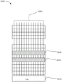
图3是包括呈图1的存储器阵列的实例3D配置的一组块的存储器装置的透视图。3 is a perspective view of a memory device including a set of blocks in an example 3D configuration of the memory array of FIG. 1 .
图4描绘图3中的一个块的一部分的实例横截面视图。FIG. 4 depicts an example cross-sectional view of a portion of a block in FIG. 3 .
图5描绘图4的堆叠的某一区的近距视图。FIG. 5 depicts a close-up view of a region of the stack of FIG. 4 .
图6描绘呈与图4一致的3D配置的子块中的NAND串的实例视图。6 depicts an example view of NAND strings in sub-blocks in a 3D configuration consistent with FIG. 4 .
图7描绘图6的子块SB0-SB3的额外细节。FIG. 7 depicts additional details of sub-blocks SB0-SB3 of FIG. 6 .
图8描绘实例编程操作的波形。8 depicts waveforms of an example programming operation.
图9描绘图5的存储器单元MC的一部分,示出了在弱编程期间到电荷捕获区的电子注入。FIG. 9 depicts a portion of memory cell MC of FIG. 5 showing electron injection into the charge trapping region during weak programming.
图10描绘根据一个实例实施例的一连串块的俯视图。Figure 10 depicts a top view of a series of blocks according to an example embodiment.
图11是根据实例实施例的编程和验证脉冲的图。Figure 11 is a diagram of program and verify pulses according to an example embodiment.
图12描绘根据一个实例实施例的两个块的一个实施例。Figure 12 depicts one embodiment of two blocks according to an example embodiment.
图13描绘用于并行编程存储器阵列的单元的方法的一个实施例。Figure 13 depicts one embodiment of a method for programming cells of a memory array in parallel.
图14描绘用于并行编程存储器阵列的单元的方法的另一实施例。Figure 14 depicts another embodiment of a method for programming cells of a memory array in parallel.
图15A、15B、15C和15D示出编程为每单元不同数目的位的存储器单元的Vt分布。Figures 15A, 15B, 15C and 15D show Vt distributions for memory cells programmed to different numbers of bits per cell.
图16是并行编程不同组存储器单元的过程的一个实施例的流程图。Figure 16 is a flowchart of one embodiment of a process for programming different groups of memory cells in parallel.
图17是并行编程不同擦除块中的NAND串的存储器单元的过程的一个实施例的流程图。Figure 17 is a flowchart of one embodiment of a process for parallel programming of memory cells of NAND strings in different erase blocks.
图18是通过多层级单元编程过程并行编程多个擦除块中的存储器单元的过程的一个实施例的流程图。Figure 18 is a flowchart of one embodiment of a process for programming memory cells in multiple erase blocks in parallel through a multi-level cell programming process.
图19是并行编程多个擦除块中的存储器单元的过程的一个实施例的流程图。Figure 19 is a flowchart of one embodiment of a process for programming memory cells in multiple erase blocks in parallel.
图20A和20B是用于在各组存储器单元的并行编程期间提供电压的电路系统的框图。20A and 20B are block diagrams of circuitry for providing voltages during parallel programming of groups of memory cells.
图21描绘图20A和20B中的电路系统可以如何电气地连接到与存储器单元的控制栅极连接的导电区的其它细节。Figure 21 depicts additional details of how the circuitry in Figures 20A and 20B may be electrically connected to the conductive regions connected to the control gates of the memory cells.
图22是在并行编程期间提供电压的过程的一个实施例的流程图。Figure 22 is a flowchart of one embodiment of a process for providing voltages during parallel programming.
图23描绘多级电荷泵的实例。Figure 23 depicts an example of a multi-stage charge pump.
具体实施方式detailed description
本文中公开了用于在多组非易失性存储器单元中并行编程相同数据模式的技术。在实施例中,相同的数据模式在三组或更多组非易失性存储器单元中并行编程。在实施例中,存储器单元被并行编程为每单元一个位。在实施例中,存储器单元被并行编程为每单元两个位。在实施例中,存储器单元被并行编程为每单元三个位。在实施例中,存储器单元被并行编程为每单元四个位。在实施例中,存储器单元被并行编程为每单元五个位。每一组非易失性存储器单元可以是不同组的NAND串的一部分。在实施例中,所述不同组的NAND串与相同位线相关联。例如,NAND串可驻留在相同平面中,此平面含有数个位线。作为实例,数据模式的n个副本可被并行编程到“n”组存储器单元中,其中n是大于1的整数。Techniques for parallel programming of the same data pattern in groups of non-volatile memory cells are disclosed herein. In an embodiment, the same data pattern is programmed in parallel in three or more groups of non-volatile memory cells. In an embodiment, memory cells are programmed in parallel with one bit per cell. In an embodiment, memory cells are programmed in parallel to two bits per cell. In an embodiment, memory cells are programmed in parallel to three bits per cell. In an embodiment, memory cells are programmed in parallel to four bits per cell. In an embodiment, memory cells are programmed in parallel to five bits per cell. Each group of non-volatile memory cells may be part of a different group of NAND strings. In an embodiment, the different sets of NAND strings are associated with the same bit line. For example, NAND strings may reside in the same plane containing several bit lines. As an example, n copies of a data pattern may be programmed into "n" groups of memory cells in parallel, where n is an integer greater than one.
在实施例中,数据模式通过向每个相应位线施加编程启用电压或编程禁止电压来施加到位线。在实施例中,向n组NAND串的漏极选择栅极施加选择电压,其中n是大于1的整数。因此,每个选定位线连接到n个选定NAND串。此外,每个选定位线连接到所述n组NAND串中的每一个中的不同NAND串。在选定位线连接到相应的n个选定NAND串时系统向n组存储器单元的控制栅极并行施加编程脉冲,并且向选定位线施加编程启用电压以将数据模式并行编程到所述n组存储单元中的每一组中。例如,所述n组存储单元中的每一组被并行编程到与数据状态相关联的阈值电压分布。In an embodiment, the data pattern is applied to the bit lines by applying a program enable voltage or a program inhibit voltage to each respective bit line. In an embodiment, a select voltage is applied to the drain select gates of n sets of NAND strings, where n is an integer greater than one. Thus, each selected bitline is connected to n selected NAND strings. Additionally, each selected bitline is connected to a different NAND string in each of the n sets of NAND strings. The system applies programming pulses in parallel to the control gates of n groups of memory cells while the selected bit lines are connected to the corresponding n selected NAND strings, and applies a program enable voltage to the selected bit lines to program the data pattern in parallel to the n groups memory cell in each group. For example, each of the n groups of memory cells is programmed in parallel to a threshold voltage distribution associated with a data state.
在一些实施例中,每一组存储器单元的控制栅极通过导电区连接。这些导电区中的每一个都可能相当大,例如三维NAND存储器阵列中的导电板。因此,可能存在与导电区相关联的大RC负载。在实施例中,在并行编程期间,使用多个电压生成器向多个导电区提供共同电压。在实施例中,系统基于要在编程操作期间接收相同量值电压的导电区的数目来启用数个电压生成器,所述编程操作将相同数据模式并行编程到n组存储器单元中。这解决了前述RC负载的技术问题。In some embodiments, the control gates of each group of memory cells are connected by a conductive region. Each of these conductive regions can be quite large, such as the conductive plates in a three-dimensional NAND memory array. Therefore, there may be a large RC load associated with the conductive region. In an embodiment, during parallel programming, multiple voltage generators are used to provide a common voltage to multiple conductive regions. In an embodiment, the system enables several voltage generators based on the number of conductive regions that are to receive voltages of the same magnitude during a programming operation that programs the same data pattern into n groups of memory cells in parallel. This solves the aforementioned technical problem of RC loads.
本公开的各方面可以体现为设备、系统、方法或计算机程序产品。本公开的各方面可采用全硬件实施例、全软件实施例(包含固件、常驻软件、微码等等)或组合了软件和硬件方面的实施例的形式,它们在本文中可全部统称为“电路”、“模块”、“设备”或“系统”。此外,本公开的各方面可采用体现在存储计算机可读和/或可执行程序代码的一个或多个非暂时性计算机可读存储媒体中的计算机程序产品的形式。Aspects of the present disclosure may be embodied as an apparatus, system, method or computer program product. Aspects of the present disclosure can take the form of an entirely hardware embodiment, an entirely software embodiment (including firmware, resident software, microcode, etc.), or an embodiment combining software and hardware aspects, all of which may be collectively referred to herein as "circuit", "module", "equipment" or "system". Additionally, aspects of the present disclosure may take the form of a computer program product embodied in one or more non-transitory computer-readable storage media storing computer-readable and/or executable program code.
在本说明书中描述的许多硬件单元都标记为电路,以便更具体地强调其实施独立性。例如,电路可以是定制VLSI电路或门阵列、全部或部分现成半导体,如逻辑芯片、晶体管或另一离散组件。电路也可以实施在可编程硬件装置中,例如现场可编程门阵列、可编程阵列逻辑、可编程逻辑装置等。值得注意的是,在叙述多个电路的情况下,在一些实例中,它们可能共享硬件元件;因此,两个不同的电路可以体现为单个硬件主体,此硬件主体经由软件或不同的硬件元件配置成执行所述两个电路的所述功能。Many of the hardware units described in this specification have been labeled as circuits, in order to more specifically emphasize their implementation independence. For example, a circuit may be a custom VLSI circuit or gate array, all or part of an off-the-shelf semiconductor such as a logic chip, a transistor, or another discrete component. Circuitry may also be implemented in programmable hardware devices, such as field programmable gate arrays, programmable array logic, programmable logic devices, and the like. It is worth noting that where multiple circuits are described, in some instances they may share hardware elements; thus, two distinct circuits may be embodied as a single body of hardware configured via software or different hardware elements. into performing the described functions of the two circuits.
用于实施本公开的各方面的操作的计算机程序代码可以用一个或多个编程语言的任何组合编写,包含:面向对象的编程语言,如Python、Java、Smalltalk、C++、C#、Objective C等等;常规的程序编程语言,如“C”编程语言、脚本处理编程语言,和/或另一类似的编程语言。程序代码可部分或完全地在用户计算机上和/或在远程计算机或服务器上通过数据网络等等执行。Computer program code for implementing operations for aspects of the present disclosure may be written in any combination of one or more programming languages, including: object-oriented programming languages such as Python, Java, Smalltalk, C++, C#, Objective C, etc. ; a conventional procedural programming language, such as the "C" programming language, a scripting programming language, and/or another similar programming language. The program code can be executed partially or completely on the user's computer and/or on a remote computer or server over a data network or the like.
如本文中所使用,组件是有形的物理非暂时性装置。例如,组件可实施为具有定制VLSI电路、门阵列或另一集成电路的硬件逻辑电路;现成半导体,例如逻辑芯片、晶体管或另一离散装置;和/或另一机械或电气装置。组件还可实施在可编程硬件装置中,例如现场可编程门阵列、可编程阵列逻辑、可编程逻辑装置等等。组件可包含一个或多个硅集成电路装置(例如,芯片、裸片、裸片平面封装)或另一离散电气装置,这些装置通过印刷电路板(PCB)的电线等与一个或多个其它组件电连通。在某些实施例中,本文中所描述的每一个模块可替代地体现为或实施为组件。As used herein, a component is a tangible, physical, non-transitory device. For example, a component may be implemented as a hardware logic circuit with custom VLSI circuits, gate arrays, or another integrated circuit; off-the-shelf semiconductors such as logic chips, transistors, or another discrete device; and/or another mechanical or electrical device. Components may also be implemented in programmable hardware devices such as field programmable gate arrays, programmable array logic, programmable logic devices, and the like. A component may consist of one or more silicon integrated circuit devices (e.g., a chip, die, die planar package) or another discrete electrical device that communicate with one or more other components via wires or the like on a printed circuit board (PCB) Electrically connected. In some embodiments, each module described herein may alternatively be embodied or implemented as a component.
贯穿本说明书对“一个实施例”、“实施例”、“一个实例实施例”或类似语言的引用意指结合所述实施例描述的特定特征、结构或特性包含在本公开的至少一个实施例中。因此,除非另有明确规定,否则贯穿本说明书的短语“在一个实施例中”、“在实施例中”和类似语言的出现可以但不一定都指同一实施例,而是指“一个或多个但不是所有实施例”。除非另有明确规定,否则术语“包含”、“包括”、“具有”及其变体均指“包含但不限于”。除非另有明确规定,否则列举的项目列表并不意味着任何或所有项目相互排斥和/或相互包含。除非另有明确规定,否则术语“一种/一(a/an)”和“所述”也指“一个或多个”。Reference throughout this specification to "one embodiment," "an embodiment," "an example embodiment," or similar language means that a particular feature, structure, or characteristic described in connection with the embodiment is included in at least one embodiment of the present disclosure. middle. Thus, appearances of the phrases "in one embodiment," "in an embodiment," and similar language throughout this specification may, but do not necessarily, all refer to the same embodiment, unless expressly stated otherwise, but instead refer to "one or more some but not all examples". Unless expressly stated otherwise, the terms "comprising", "including", "having" and variations thereof mean "including but not limited to". Unless expressly stated otherwise, an enumerated listing of items does not imply that any or all of the items are mutually exclusive and/or inclusive. The terms "a/an" and "the" also mean "one or more" unless expressly stated otherwise.
下文参考根据本公开的实施例的方法、设备、系统和计算机程序产品的示意性流程图和/或示意性框图来描述本公开的各方面。应理解,示意性流程图和/或示意性框图中的每个框及示意性流程图和/或示意性框图中的框的组合可由计算机程序指令实施。这些计算机程序指令可被提供给计算机的处理器或另一可编程数据处理设备以产生机器,使得经由所述处理器或另一可编程数据处理设备执行的所述指令形成用于实施在示意性流程图和/或示意性框图的一个或多个框中指定的功能和/或动作的构件。Aspects of the present disclosure are described below with reference to schematic flowchart illustrations and/or schematic block diagrams of methods, apparatuses, systems and computer program products according to embodiments of the disclosure. It will be understood that each block of the flowchart illustrations and/or block diagrams, and combinations of blocks in the flowchart illustrations and/or block diagrams, can be implemented by computer program instructions. These computer program instructions may be provided to a processor of a computer or another programmable data processing device to produce a machine such that execution of said instructions via said processor or another programmable data processing device forms the A component of a function and/or action specified in one or more blocks of a flowchart and/or schematic block diagram.
还应注意,在一些替代实施方案中,框中标注的功能可能与图中标注的顺序不符。例如,连续示出的两个框实际上可以基本上并行执行,或者这些框有时可以相反顺序执行,这取决于所涉及的功能。可以设想在功能、逻辑或效果上等同于所示附图的一个或多个框或其部分的其它步骤和方法。尽管在流程图和/或框图中可以使用各种箭头类型和线型,但是可以理解,它们并不限制对应实施例的范围。举例来说,箭头可指示所描绘实施例的列举步骤之间的未指定持续时间的等待或监测时段。It should also be noted that, in some alternative implementations, the functions noted in the blocks may occur out of the order noted in the figures. For example, two blocks shown in succession may, in fact, be executed substantially concurrently, or the blocks may sometimes be executed in the reverse order, depending upon the functionality involved. Other steps and methods may be conceived that are equivalent in function, logic, or effect to one or more blocks of the illustrated figures, or portions thereof. Although various arrow types and line styles may be used in flowcharts and/or block diagrams, it is understood that they do not limit the scope of the corresponding embodiments. For example, an arrow may indicate a waiting or monitoring period of unspecified duration between enumerated steps of the depicted embodiment.
在以下详细描述中,参考附图,这些附图构成描述的一部分。上述概述仅为说明性的,并不打算以任何方式限制。除了上述说明性方面、实施例和特征之外,通过参考附图和以下详细描述,其它方面、实施例和特征将变得显而易见。每个图中的元件描述可参考先前图中的元件。类似数字可指图中的类似元件,包含类似元件的替代实施例。In the following detailed description, reference is made to the accompanying drawings, which form a part hereof. The foregoing summary is illustrative only and is not intended to be limiting in any way. In addition to the illustrative aspects, embodiments and features described above, further aspects, embodiments and features will become apparent by reference to the drawings and the following detailed description. Descriptions of elements in each figure may refer to elements in previous figures. Like numbers may refer to like elements in the figures, including alternative embodiments of like elements.
图1A是具有非易失性存储器装置120的并行编程组件150的系统100的一个实施例的框图。并行编程组件150可以是非易失性存储器媒体控制器126(如图1A中所描绘)、非易失性存储器元件123、装置驱动器等等的一部分和/或与其通信。并行编程组件150可在计算装置110的非易失性存储器系统102上操作,所述计算装置可包含处理器111、易失性存储器112和网络接口113。处理器111可包含一个或多个中央处理单元、一个或多个通用处理器、一个或多个专用处理器、一个或多个虚拟处理器(例如,计算装置110可以是在主机内操作的虚拟机)、一个或多个处理器核心等等。网络接口113可包含配置成以通信方式将计算装置110和/或非易失性存储器媒体控制器126耦合到通信网络115的一个或多个网络接口,所述通信网络例如是互联网协议(IP)网络、存储区域网络(SAN)、无线网络、有线网络等等。FIG. 1A is a block diagram of one embodiment of a
在各种实施例中,非易失性存储器装置120可相对于计算装置110安置在一个或多个不同位置。在一个实施例中,非易失性存储器装置120包含一个或多个非易失性存储器元件123,例如半导体芯片或封装或安置在一个或多个印刷电路板、存储壳体和/或其它机械和/或电气支撑结构上的其它集成电路装置。例如,非易失性存储器装置120可包含一个或多个直接内联存储器模块(DIMM)卡、一个或多个扩展卡和/或子卡、固态驱动器(SSD)或其它硬盘驱动器装置,和/或可具有另一存储器和/或存储外观尺寸。非易失性存储器装置120可与计算装置110的主板集成和/或安装在所述主板上,安装于计算装置110的端口和/或槽中,安装于通信网络115上的另一计算装置110和/或专用存储设备上,通过外部总线(例如,外部硬盘驱动器)与计算装置110通信,等等。In various embodiments, non-volatile memory device 120 may be disposed in one or more different locations relative to computing device 110 . In one embodiment, nonvolatile memory device 120 includes one or more
在一个实施例中,非易失性存储器装置120可安置在处理器111的存储器总线上(例如,在与易失性存储器112相同的存储器总线上、在与易失性存储器112不同的存储器总线上、代替易失性存储器112等等)。在另一实施例中,非易失性存储器装置120可安置在计算装置110的外围总线上,例如外围组件互连高速(PCI Express或PCIe)总线、串行高级技术附件(SATA)总线、并行高级技术附件(PATA)总线、小型计算机系统接口(SCSI)总线、FireWire总线、光纤通道连接、通用串行总线(USB)、PCIe高级交换(PCIe-AS)总线等等。在另一实施例中,非易失性存储器装置120可安置在通信网络115上,例如以太网网络、Infiniband网络、通过通信网络115的SCSI RDMA、存储区域网络(SAN)、局域网(LAN)、互联网等广域网(WAN)、另一有线和/或无线网络,等等。In one embodiment, non-volatile memory device 120 may be disposed on a memory bus of processor 111 (e.g., on the same memory bus as
计算装置110可进一步包含非暂时性计算机可读存储媒体114。计算机可读存储媒体114可具有配置成使计算装置110(例如,处理器111)执行本文所公开的一个或多个方法的步骤的可执行指令。替代地或另外,并行编程组件150可体现为存储在计算机可读存储媒体114上的一个或多个计算机可读指令。Computing device 110 may further include a non-transitory computer-
在描绘的实施例中,非易失性存储器系统102包含并行编程组件150。如将进一步描述,并行编程组件150可配置成电气地选择布置到相同块或两个不同块中的一组非易失性存储单元的位线,电气地连接对应于存储单元的单独字线,并且向连接字线的施加编程脉冲以将对应于单独字线的存储单元并行编程到共同目标阈值电压。存储单元可以任选地位于两个不同块中,这两个块可在存储器阵列内彼此物理地分开,以最大限度地减少在其中一个存储单元中出现的误差还会存在于另一存储单元中的概率。如本文中所使用,“电气地选择”包含施加允许电流源传送到另一组件的电位。在一个实例中,电气地选择位线包含设置一个或多个硬件组件以将所述位线连接到另一组件。In the depicted embodiment, non-volatile memory system 102 includes
并行编程组件150可以利用相同数据并行编程单独块中的单独单元,并将它们编程到共同目标阈值电压。在一些实施例中,向单独块并行写入相同数据提供了提高的性能,因为如果一个块未能存储写入的数据,那么数据可以从另一块恢复而无需再次向非易失性存储器媒体控制器126请求数据。这使得系统100能够更快速地移到其它操作,因为所需要的来自非易失性存储器媒体控制器126的请求更少。The
此外,在一些实施例中,使用相同数据的两个副本的单元压缩操作可以在单独块中使用相同数据,非易失性存储器媒体控制器126不必单独地写入数据的另一副本。这简化了由参与MLC、TLC QLC编程等等的非易失性存储器媒体控制器126执行的操作。Furthermore, in some embodiments, a cell compression operation using two copies of the same data may use the same data in separate blocks without the non-volatile memory media controller 126 having to write the other copy of the data separately. This simplifies the operations performed by the non-volatile memory media controller 126 involved in MLC, TLC QLC programming, and the like.
在一个实例实施例中,并行编程组件150向位于物理上单独的区中的块写入相同数据。这些单独区可以通过距离、选定块之间的块数等来定义。如本领域技术人员可以理解的,NAND单元阵列可能会在特定物理位置或区域发生故障。将相同数据写入NAND阵列的物理上相距甚远的区域可提供更高的故障保护,因为如果NAND阵列的特定部分发生故障,那么存在于不同物理位置的数据的第二副本可能不会受到影响。如本文所描述,在一些实施例中,由于并行编程组件150并行地写入相同数据的两个副本,因此这一益处不需要额外的操作(例如,与将数据写入第一单元相比,将相同数据写入第二单元不需要额外的时间)。In one example embodiment,
在另一实例实施例中,并行编程组件150向相同串中的两个单独单元写入相同数据。将一个串中的多个单元并行编程到共同目标阈值电压可提供与向单独块写入类似的益处。除了先前描述的益处之外,将一个串中的两个连续单元并行编程到共同目标阈值电压可以减少电气干扰,因为对应于所编程的相同单元的两个字线同时经受相同的电压偏置。此外,在此情形中,字线到字线电容减小。并行编程组件150可向所述串中不同位置处的单元写入相同数据以提供物理分离,如先前结合向单独块并行写入所描述。In another example embodiment,
在另一实例实施例中,在验证第一单元已经正确地编程之后,并行编程组件150可舍弃第二单元中的数据。并行编程组件150可通过擦除第二单元、将第二单元标记用于重复使用或使用其它数据覆写第二单元来达成这一目的。另外或替代地,这两个单元中的数据可以在例如用于单元压缩操作之前一直保留,在单元压缩操作中,数据与其它数据组合并存储在多层级单元(MLC)等等(例如,TLC、QLC等)中。In another example embodiment, after verifying that the first cell has been programmed correctly,
在一些实施例中,在用于例如三层级单元(TLC)的多层级单元(MLC)的数据已经临时存储在一连串SLC单元中之后可以使用SLC-TLC压缩操作(单元压缩操作的一个实例)。在一些实施例中,三对SLC单元可用于存储TLC的数据,其中出于数据冗余目的,每一对针对要存储在TLC中的单个位存储相同版本的数据。在SLC-TLC压缩中,来自所述三对SLC单元中的每一对中的至少一个SLC单元的数据可读取并被编码成TLC内的位,使得有三个位在TLC上编码。在TLC中编码的位可以任选地与所述三对SLC的那些进行比较,以确认TLC已经正确地编程。然后,在TLC正确地编程后,SLC就可以擦除。接着,相同SLC单元可用作TLC编程的缓冲器,其中内置有临时数据冗余。In some embodiments, an SLC-TLC compression operation (an example of a cell compression operation) may be used after data for a multi-level cell (MLC), such as a triple-level cell (TLC), has been temporarily stored in a chain of SLC cells. In some embodiments, three pairs of SLC cells may be used to store data for the TLC, where each pair stores the same version of the data for a single bit to be stored in the TLC for data redundancy purposes. In SLC-TLC compression, data from at least one SLC cell in each of the three pairs of SLC cells can be read and encoded into bits within the TLC such that three bits are encoded on the TLC. The bits encoded in the TLC can optionally be compared to those of the three pairs of SLCs to confirm that the TLC has been programmed correctly. Then, after the TLC is properly programmed, the SLC can be erased. Then, the same SLC cells can be used as buffers for TLC programming, with temporary data redundancy built in.
在单元压缩操作之后,第一和第二单元均可被擦除。可以使用新的编程操作来用例如要用于另一SLC-TLC压缩操作中的新数据编程单元。从单元擦除数据以及用新数据编程单元(或在要存储的新数据涉及处于已擦除或未编程状态的单元的保留的情况下的进行不编程单元的确定)的组合被称为“覆写”单元的内容。After a cell compaction operation, both the first and second cells can be erased. A new programming operation can be used to program the cell with new data to be used in another SLC-TLC compression operation, for example. The combination of erasing data from a cell and programming the cell with new data (or making a determination not to program a cell in the case where the new data to be stored involves the retention of a cell in an erased or unprogrammed state) is called "overwriting". Write" the content of the unit.
如本文中所使用,“块”包括一组字线,其中每个字线连接到一组存储单元。在一个实例实施例中,“块”包括存储单元(例如,非易失性存储器元件)阵列的一部分,其中存储单元以一种允许在单个操作中擦除块中的所有存储单元的方式连接。本领域的技术人员将认识到,块是可以使用单个存储/存储器擦除命令擦除的存储单元的最小单位,并且在某些实施例中可被称为“擦除块”。在某些实施例中,“块”包含一组非易失性存储器元件串。As used herein, a "block" includes a set of word lines, where each word line is connected to a set of memory cells. In one example embodiment, a "block" includes a portion of an array of memory cells (eg, non-volatile memory elements) connected in a manner that allows all memory cells in the block to be erased in a single operation. Those skilled in the art will recognize that a block is the smallest unit of memory cells that can be erased using a single store/memory erase command, and may be referred to as an "erase block" in some embodiments. In some embodiments, a "block" includes a set of strings of non-volatile memory elements.
如本文中所使用,“NAND串”包括通过NAND沟道串联地电气连接到位线的一组NAND存储单元。“NAND沟道”包含将NAND串中的存储单元连接到它们相应的位线和源极线的电气连接(例如,图5:沟道665)。NAND串上的存储单元的控制栅极可连接到导电区,使得电压能够被施加到控制栅极。如本文中所使用,“位线”包含可连接到电压源且可连接到NAND串的末端(例如,经由NAND沟道)的导电材料线。在一个实例中,块包含64个串,并且单独的位线可连接到所述64个串中的每一个。在另一实例中,位线通行穿过许多块,并且可连接到每个块中的对应串。As used herein, a "NAND string" includes a group of NAND memory cells electrically connected in series to a bit line through a NAND channel. A "NAND channel" comprises the electrical connections that connect the memory cells in a NAND string to their corresponding bit and source lines (eg, Figure 5: channel 665). The control gates of the memory cells on the NAND string can be connected to the conductive region so that a voltage can be applied to the control gates. As used herein, a "bit line" includes a line of conductive material that can be connected to a voltage source and can be connected to the end of a NAND string (eg, via a NAND channel). In one example, a block contains 64 strings, and a separate bit line can be connected to each of the 64 strings. In another example, bit lines run through many blocks and can be connected to corresponding strings in each block.
如本文中所使用,“相交”包括两个组件(例如,字线、位线、存储单元等)物理地布置成使得可以电气地影响彼此。字线与存储单元相交意指字线电气地连接到存储单元,使得向字线施加编程脉冲编程了存储单元。As used herein, "intersecting" includes two components (eg, word lines, bit lines, memory cells, etc.) physically arranged so as to electrically affect each other. A word line intersecting a memory cell means that the word line is electrically connected to the memory cell such that applying a programming pulse to the word line programs the memory cell.
如本文所使用,“可电气连接”包含两个组件(例如,字线、位线、存储单元等)配置和/或定位成易于连接以准许电流在它们之间通过。可电气连接性可涉及使用次要组件连接所述可电气连接组件。在一个实例中,栅极晶体管可设置成将字线电气连接到电压源。因此,字线和电压源彼此可电气连接,但是除非有栅极晶体管将它们连接,否则它们彼此不形成电气连接。As used herein, "electrically connectable" includes two components (eg, word lines, bit lines, memory cells, etc.) configured and/or positioned for easy connection to permit electrical current to pass between them. Electrical connectability may involve connecting said electrically connectable components using secondary components. In one example, a gate transistor may be configured to electrically connect the word line to a voltage source. Thus, the word line and the voltage source are electrically connectable to each other, but are not electrically connected to each other unless there is a gate transistor connecting them.
如本文所使用,“并行编程(concurrently program/concurrentlyprogramming)”、“并行施加编程脉冲”等等意指基本上同时地向两个或更多个单独存储单元施加编程脉冲。“基本上同时”意指所述两个或更多个单元由相同编程脉冲编程,但是由于物理位置或电气距离,存储单元可能无法在完全相同的时间接收到编程脉冲。在一个实例中,由于与编程脉冲源相隔的物理距离,第一存储单元可在第二存储单元之前接收编程脉冲。在另一实例实施例中,所述两个或更多个存储单元同时接收编程脉冲,但是第一存储单元在第二存储单元之前成功地编程。此外,将多个存储单元并行编程到共同目标阈值电压意指基本上同时地向所述存储单元中的每一个施加共同电压。当然,如本领域技术人员可以理解的,这不一定意指存储单元是由于相同脉冲而成功地编程到目标阈值电压的。As used herein, "concurrently program/concurrently programming," "applying programming pulses in parallel," and the like means applying programming pulses to two or more separate memory cells substantially simultaneously. "Substantially simultaneously" means that the two or more cells are programmed by the same programming pulse, but due to physical location or electrical distance, the memory cells may not receive the programming pulse at exactly the same time. In one example, a first memory cell may receive a programming pulse before a second memory cell due to the physical distance from the source of the programming pulse. In another example embodiment, the two or more memory cells receive programming pulses at the same time, but the first memory cell is successfully programmed before the second memory cell. Furthermore, programming a plurality of memory cells in parallel to a common target threshold voltage means applying a common voltage to each of the memory cells substantially simultaneously. Of course, this does not necessarily mean that the memory cells were successfully programmed to the target threshold voltage due to the same pulse, as would be appreciated by those skilled in the art.
在一个实施例中,并行编程组件150可包含一个或多个非易失性存储器装置120的逻辑硬件,例如非易失性存储器媒体控制器126、非易失性存储器元件123、装置控制器、现场可编程门阵列(FPGA)或其它可编程逻辑、用于FPGA或其它可编程逻辑的固件、用于在微控制器上执行的微码、专用集成电路(ASIC)等等。在另一实施例中,并行编程组件150可包含在计算机可读存储媒体114上存储以在处理器111上执行的可执行软件代码,例如装置驱动器等等。在另一实施例中,并行编程组件150可包含可执行软件代码和逻辑硬件两者的组合。In one embodiment,
在一个实施例中,并行编程组件150配置成经由总线125等从装置驱动器或其它可执行应用程序接收存储请求。并行编程组件150可进一步配置成经由总线125向/从装置驱动器和/或存储客户端116传送数据。相应地,在一些实施例中,并行编程组件150可包含一个或多个直接存储器存取(DMA)模块、远程DMA模块、总线控制器、桥、缓冲器等等和/或可与其通信,以促进存储请求和相关联数据的传送。在另一实施例中,并行编程组件150可接收存储请求,如来自存储客户端116的API调用、IO-CTL命令等等。In one embodiment,
根据各种实施例,与一个或多个程序排序组件140通信的非易失性存储器媒体控制器126可管理一个或多个非易失性存储器装置120和/或非易失性存储器元件123。非易失性存储器装置120可包含记录、存储器和/或存储装置,例如固态存储装置和/或半导体存储装置,它们布置和/或分割成多个可寻址媒体存储位置。如本文中所使用,媒体存储位置是指存储器的任何物理单元(例如,非易失性存储器装置120上的任何数量的物理存储媒体)。存储器单元可包含但不限于:页、存储器分区、块、扇区、物理存储位置集合或组(例如,逻辑页、逻辑块)等等。According to various embodiments, a non-volatile memory media controller 126 in communication with one or more
在某些实施例中,装置驱动器和/或非易失性存储器媒体控制器126可向存储客户端116呈现逻辑地址空间134。如本文中所使用,逻辑地址空间134是指存储器资源的逻辑表示。逻辑地址空间134可包含多个(例如,一系列)逻辑地址。如本文中所使用,逻辑地址是指用于引用存储器资源(例如,数据)的任何标识符,包含但不限于:逻辑块地址(LBA)、柱面/磁头/扇区(CHS)地址、文件名、对象标识符、索引节、通用唯一标识符(UUID)、全局唯一标识符(GUID)、散列代码、签名、索引条目、范围、程度等等。In certain embodiments, device drivers and/or non-volatile memory media controller 126 may present logical address space 134 to storage client 116 . As used herein, logical address space 134 refers to a logical representation of memory resources. Logical address space 134 may contain a plurality (eg, a range) of logical addresses. As used herein, a logical address refers to any identifier used to refer to a memory resource (e.g., data), including but not limited to: Logical Block Address (LBA), Cylinder/Head/Sector (CHS) address, file Names, object identifiers, inodes, universally unique identifiers (UUIDs), globally unique identifiers (GUIDs), hash codes, signatures, index entries, ranges, degrees, and more.
非易失性存储器装置120的装置驱动器可维持元数据135,例如逻辑到物理地址映射结构,以将逻辑地址空间134的逻辑地址映射到非易失性存储器装置120上的媒体存储位置。装置驱动器可配置成向一个或多个存储客户端116提供存储服务。存储客户端116可包含在计算装置110上操作的本地存储客户端和/或可经由通信网络115和/或网络接口113访问的远程存储客户端116。存储客户端116可包含但不限于:操作系统、文件系统、数据库应用程序、服务器应用程序、核级进程、用户级进程、应用程序等等。A device driver for nonvolatile memory device 120 may maintain metadata 135 , such as a logical-to-physical address mapping structure, to map logical addresses of logical address space 134 to media storage locations on nonvolatile memory device 120 . The device driver may be configured to provide storage services to one or more storage clients 116 . Storage clients 116 may include local storage clients operating on computing device 110 and/or remote storage clients 116 accessible via communication network 115 and/or
装置驱动器可以通信方式耦合到一个或多个非易失性存储器装置120。所述一个或多个非易失性存储器装置120可包含不同类型的非易失性存储器装置,包含但不限于:固态存储装置、半导体存储装置、SAN存储资源等等。所述一个或多个非易失性存储器装置120可包含一个或多个相应非易失性存储器媒体控制器126和非易失性存储器媒体122。装置驱动器可经由传统的块I/O接口131提供对所述一个或多个非易失性存储器装置120的访问。另外,装置驱动器可通过SCM接口132提供对增强功能的访问。元数据135可用于管理和/或跟踪通过块I/O接口131、SCM接口132、高速缓存接口133或其它相关接口中的任一个执行的数据操作。A device driver may be communicatively coupled to one or more non-volatile memory devices 120 . The one or more non-volatile memory devices 120 may include different types of non-volatile memory devices, including but not limited to: solid-state storage devices, semiconductor storage devices, SAN storage resources, and the like. The one or more non-volatile memory devices 120 may include one or more corresponding non-volatile memory media controllers 126 and
高速缓存接口133可暴露经由非易失性存储器装置120的装置驱动器可以访问的高速缓存特定特征。并且,在一些实施例中,呈现给存储客户端116的SCM接口132提供对由所述一个或多个非易失性存储器装置120和/或所述一个或多个非易失性存储器媒体控制器126实施的数据变换的访问。The cache interface 133 may expose cache-specific features accessible via a device driver of the non-volatile memory device 120 . Also, in some embodiments, the SCM interface 132 presented to the storage client 116 provides control over the storage media provided by the one or more non-volatile memory devices 120 and/or the one or more non-volatile memory media. Access to data transformations implemented by the implementer 126.
装置驱动器可通过一个或多个接口向存储客户端116呈现逻辑地址空间134。如上文所论述,逻辑地址空间134可包含多个逻辑地址,每个逻辑地址对应于所述一个或多个非易失性存储器装置120的相应媒体位置。装置驱动器可维持元数据135,包含逻辑地址和媒体位置之间的任意映射,等等。A device driver may present logical address space 134 to storage client 116 through one or more interfaces. As discussed above, logical address space 134 may include a plurality of logical addresses, each corresponding to a respective media location of the one or more non-volatile memory devices 120 . The device driver may maintain metadata 135, including arbitrary mappings between logical addresses and media locations, among others.
装置驱动器可进一步包含配置成通过总线125向所述一个或多个非易失性存储器装置120传送数据、命令和/或询问的非易失性存储器装置接口139和/或与其通信,所述总线可包含但不限于:处理器111的存储器总线、外围组件互连高速(PCI Express或PCIe)总线、串行高级技术附件(ATA)总线、并行ATA总线、小型计算机系统接口(SCSI)、FireWire、光纤通道、通用串行总线(USB)、PCIe高级交换(PCIe-AS)总线、通信网络115、Infiniband、SCSI RDMA等等。非易失性存储器装置接口139可使用输入-输出控制(IO-CTL)命令、IO-CTL命令扩展、远程直接存储器存取等等与所述一个或多个非易失性存储器装置120通信。The device driver may further include and/or communicate with a non-volatile memory device interface 139 configured to transmit data, commands, and/or queries to the one or more non-volatile memory devices 120 via the
网络接口113可包含配置成以通信方式将计算装置110和/或非易失性存储器媒体控制器126耦合到通信网络115和/或一个或多个远程的网络可访问存储客户端116的一个或多个网络接口。存储客户端116可包含在计算装置110上操作的本地存储客户端和/或可经由通信网络115和/或网络接口113访问的远程存储客户端116。非易失性存储器媒体控制器126是一个或多个非易失性存储器装置120的部分和/或与其通信。尽管图1A描绘了单个非易失性存储器装置120,但是本公开在此方面不受限制,并且可调适成并入有任何数目个非易失性存储器装置120。
非易失性存储器装置120可包含非易失性存储器媒体122的一个或多个非易失性存储器元件123,所述非易失性存储器媒体可包含但不限于:ReRAM、忆阻器存储器、可编程金属化单元存储器、相变存储器(PCM、PCME、PRAM、PCRAM、双向统一存储器、硫族化物RAM或C-RAM)、NAND快闪存储器(例如,2D NAND快闪存储器、3D NAND快闪存储器)、NOR快闪存储器、纳米随机存取存储器(纳米RAM或NRAM)、纳米晶线基存储器、氧化硅基亚10纳米工艺存储器、石墨烯存储器、硅-氧化物-氮化物-氧化物-硅(SONOS)、可编程金属化单元(PMC)、导电桥接RAM(CBRAM)、磁阻RAM(MRAM)、自旋转移力矩(STT)MRAM、自旋轨道力矩SOT-MRAM、磁存储媒体(例如,硬盘、磁带)、光学存储媒体等等。在某些实施例中,非易失性存储器媒体122的所述一个或多个非易失性存储器元件123包含存储类存储器(SCM)。本文中的实例参考的是NAND存储器,或更具体地说,参考的是SLC NAND存储器;但是,本文所提供的系统和方法可应用于其它存储器类型,包含但不限于上文所列的那些。The non-volatile memory device 120 may include one or more
尽管诸如NAND快闪之类的传统技术可以是块和/或页可寻址的,但在一个实施例中,存储类存储器是字节可寻址的。在其它实施例中,存储类存储器可以比NAND快闪更快和/或具有更长的寿命(例如,耐久性);相比于DRAM可具有更低的成本、更少的功耗和/或更高的存储密度;或者与其它技术相比,提供一个或多个其它益处或改进。例如,存储类存储器可包含以下的一个或多个非易失性存储器元件123:ReRAM、忆阻器存储器、可编程金属化单元存储器、相变存储器、纳米RAM、纳米晶线基存储器、氧化硅基亚10纳米工艺存储器、石墨烯存储器、SONOS存储器、MANOS存储器、PMC存储器、CBRAM、MRAM和/或其变化形式。While conventional technologies such as NAND flash may be block and/or page addressable, in one embodiment storage class memory is byte addressable. In other embodiments, storage class memory may be faster and/or have a longer lifetime (e.g., endurance) than NAND flash; may have lower cost, less power consumption, and/or higher storage density; or provide one or more other benefits or improvements over other technologies. For example, storage class memory may comprise one or more of the following non-volatile memory elements 123: ReRAM, memristor memory, programmable metallization cell memory, phase change memory, nano-RAM, nanocrystalline wire-based memory, silicon oxide Substrate 10nm process memory, graphene memory, SONOS memory, MANOS memory, PMC memory, CBRAM, MRAM and/or variations thereof.
尽管非易失性存储器媒体122在本文中称为“存储器媒体”,但是在各种实施例中,非易失性存储器媒体122可以更一般地包含能够记录数据的一个或多个非易失性记录媒体,其可被称为非易失性存储器媒体、非易失性存储媒体等等。此外,在各种实施例中,非易失性存储器装置120可包含非易失性记录装置、非易失性存储器装置、非易失性存储装置等等。Although
非易失性存储器媒体122可包含一个或多个非易失性存储器元件123,其可包含但不限于:芯片、封装、平面、裸片等等。非易失性存储器媒体控制器126可配置成管理非易失性存储器媒体122上的数据操作,并且可包含一个或多个处理器、可编程处理器(例如,FPGA)、ASIC、微控制器等等。在一些实施例中,非易失性存储器媒体控制器126配置成在非易失性存储器媒体122上存储数据和/或从其读取数据、向/从非易失性存储器装置120传送数据,等等。The
非易失性存储器媒体控制器126可通过总线127以通信方式耦合到非易失性存储器媒体122。总线127可包含用于向/从非易失性存储器元件123传送数据的I/O总线。总线127可进一步包含用于向非易失性存储器元件123传送寻址和其它命令与控制信息的控制总线。在一些实施例中,总线127可以通信方式将非易失性存储器元件123并联地耦合到非易失性存储器媒体控制器126。这一并行访问可允许非易失性存储器元件123作为一个群组受管理,从而形成逻辑存储器元件129。逻辑存储器元件可分割成相应的逻辑存储器单元(例如,逻辑页)和/或逻辑存储器分区(例如,逻辑块)。逻辑存储器单元可通过在逻辑上组合每一个非易失性存储器元件的物理存储器单元来形成。Non-volatile memory media controller 126 may be communicatively coupled to
在某些实施例中,非易失性存储器媒体控制器126可使用字线的地址组织非易失性存储器元件123内的字线块,使得字线在逻辑上组织成单调递增序列(例如,将字线的地址解码和/或转换成单调递增序列,等等)。在另一实施例中,非易失性存储器元件123内的块的字线可以按照字线地址的单调递增序列物理地布置,其中连续寻址的字线也是物理邻近的(例如,WL0、WL1、WL2、……WLN)。In some embodiments, the nonvolatile memory media controller 126 may use the addresses of the wordlines to organize blocks of wordlines within the
非易失性存储器媒体控制器126可包含在计算装置110上执行的装置驱动器和/或可与其通信。装置驱动器可经由一个或多个接口131、132和/或133向存储客户端116提供存储服务。在一些实施例中,装置驱动器提供存储客户端116用来执行块层级I/O操作的块I/O接口131或装置接口。替代地或另外,装置驱动器可提供存储类存储器(SCM)接口132,此接口可向存储客户端116提供其它存储服务。在一些实施例中,SCM接口132可包含块I/O接口131的扩展(例如,存储客户端116可通过块I/O接口131的扩展或添加访问SCM接口132)。替代地或另外,SCM接口132可以提供为单独API、服务和/或库。装置驱动器可进一步配置成提供高速缓存接口133,用于使用非易失性存储器系统102缓存数据。Non-volatile memory media controller 126 may include and/or may be in communication with device drivers executing on computing device 110 . Device drivers may provide storage services to storage clients 116 via one or
装置驱动器可进一步包含配置成通过总线125向非易失性存储器媒体控制器126传送数据、命令和/或询问的非易失性存储器装置接口139,如上文所描述。The device driver may further include a non-volatile memory device interface 139 configured to communicate data, commands and/or queries to the non-volatile memory media controller 126 over the
图1B示出可包含一个或多个存储器裸片212或芯片的非易失性存储装置210的实施例。在一些实施例中,存储器裸片212包含存储器单元的存储器阵列200(二维或三维)、裸片控制器220和读取/写入电路230A/230B。在一个实施例中,各个外围电路对存储器阵列200的访问在阵列的相对侧面上以对称方式实施,使得每一侧上的存取线和电路系统的密度减小一半。在另一实施例中,读取/写入电路230A/230B包含允许存储器单元页进行并行读取或编程的多个感测块250。FIG. 1B illustrates an embodiment of a
在各种实施例中,存储器阵列200可通过字线经由行解码器240A/240B以及通过位线经由列解码器242A/242B寻址。在一些实施例中,控制器244与所述一个或多个存储器裸片212包含在相同的非易失性存储装置210(例如,可拆卸式存储卡或封装)中。命令和数据在主机和控制器244之间经由线232传送,且在控制器和所述一个或多个存储器裸片212之间经由线234传送。一个实施方案可包含多个存储器裸片212。In various embodiments,
裸片控制器220可与存储器阵列200共享裸片,使得裸片控制器220构成“裸片上”控制器。裸片控制器220可具有本领域中已知的任何形式,包含但不限于微处理器、微控制器单元(MCU)、有限状态机(FSM)、中央处理单元(CPU)、图形处理单元(GPU)等等;“裸片上控制器”或“控制器”均可指代这些中的任一个。Die controller 220 may share a die with
在一个实施例中,裸片控制器220与读取/写入电路230A/230B配合在存储器阵列200上执行存储器操作。在某些实施例中,裸片控制器220包含并行编程组件150、状态机222和芯片上地址解码器224。在一个实施例中,状态机222形成并行编程组件150的一部分。在另一实施例中,控制器244形成并行编程组件150的一部分。控制器244可以任选地定位在一个或多个存储器裸片212上,或者可以在与存储器裸片212分开的裸片上。In one embodiment, die controller 220 cooperates with read/write circuits 230A/ 230B to perform memory operations on
在一些实施例中,每一个存储器阵列200可以是SLC(单层级单元)NAND阵列,其中每一个非易失性存储器元件123或“非易失性存储单元”可经由跨所述单元施加编程脉冲来编程。每一个存储器阵列200可进一步利用单个脉冲编程,从而提供接近编程NAND的理论极限的速度。如本领域中已知,每一个非易失性存储器元件123可具有电气绝缘元件,例如栅极氧化层或隧道氧化层,电子可选择性地移动通过此元件,此元件通过允许用电荷对单元进行编程并保留用以编程的电荷来提供栅极功能。“绝缘元件”或“绝缘层”可包含设计成选择性地准许电荷进入和/或离开非易失性存储单元的任何结构。In some embodiments, each
短语“编程脉冲(programming pulse/program pulse)”是指施加到非易失性存储器元件123使非易失性存储器元件123进入或迈向已编程状态的电脉冲。这可以是峰值电压值、均方根(“RMS”)电压值、脉冲的平均电压、脉冲序列中特定脉冲的电压值等。在另一实例实施例中,编程脉冲包含施加电流,包含峰值电流、RMS电流值、脉冲的平均电流或特定电流序列等。“编程脉冲”不限于NAND存储器,而是可以施加到通过施加电位来编程的任何非易失性存储器。因此,在包含但不限于上文背景技术部分中列出的非易失性存储器类型的非易失性存储器类型中,可以通过使用本公开的系统和方法调整编程设置,例如编程脉冲。The phrase "programming pulse" refers to an electrical pulse applied to the
短语“验证脉冲”包含施加到非易失性存储器元件123(例如,存储单元)且由此电流指示存储单元是否已经充分编程的电气脉冲。不同存储单元的验证脉冲可以相同也可以不同。The phrase "verify pulse" includes an electrical pulse that is applied to a non-volatile memory element 123 (eg, a memory cell) and whereby a current flow indicates whether the memory cell has been sufficiently programmed. The verification pulses of different memory cells can be the same or different.
类似地,各个“感测设置”可用于感测存储器阵列200的一个或多个非易失性存储器元件123的内容。术语“感测”不仅指代具有保持电荷的单元的非易失性存储器结构,而且还指代其中使用不同存储机构的非易失性存储器类型。例如,在一些非易失性存储器类型中,使用电压和/或电流来感测单元(而不是所存储电荷)的电阻电平。在其它非易失性存储器类型中,检测流动通过单元的电流;高于或低于特定阈值的电流电平可指示单元经编程。在要确定各个单元的内容时,这可被称为“读取”单元。但是,“感测”非易失性存储器阵列的内容可包含读取各个单元的内容,或检测单元的单独或集体特性,例如单元的电压或电阻是高于还是低于预定阈值。Similarly, various “sense settings” may be used to sense the contents of one or more
在一些实施例中,修改编程设置可包含减小在非易失性存储器装置120的操作寿命期间跨非易失性存储器元件123施加一次或多次的编程电压,从而延长非易失性存储器装置120的使用寿命并降低由于单元过度编程而出现错误数据读取的可能性。In some embodiments, modifying the programming settings may include reducing the programming voltage applied across the
在一个实施例中,状态机222提供存储器操作的芯片级控制。芯片上地址解码器224提供地址接口,以在供主机或存储器控制器使用的地址与供解码器240A、240B、242A、242B使用的硬件地址之间转换。在某些实施例中,状态机222包含并行编程组件150的实施例。In one embodiment, state machine 222 provides chip-level control of memory operations. On-chip address decoder 224 provides an address interface to translate between addresses used by the host or memory controller and hardware addresses used by decoders 240A, 240B, 242A, 242B. In some embodiments, state machine 222 includes an embodiment of
在一个实施例中,裸片控制器220、并行编程组件150、芯片上地址解码器224、状态机222、解码器242A、解码器242B、解码器240A、解码器240B、读取/写入电路230A、读取/写入电路230B和/或控制器244中的一个或其任何组合可被称为一个或多个管理电路。在一个实例实施例中,裸片控制器220包含选择电路282、编程电路284和验证电路286中的任一个。In one embodiment, die controller 220,
在另一实例实施例中(在图1B中未描绘),选择电路282、编程电路284和验证电路286实施为控制器244的部分。在又一实例实施例中,裸片控制器220包括电路282、284、286中的一个或多个,并且控制器244包括电路282、284、286中的一个或多个。因此,不需要在裸片控制器220或控制器244上实施各个电路282、284、286。In another example embodiment (not depicted in FIG. 1B ),
选择电路282可配置成电气地选择第一擦除块中的第一组存储单元和第二擦除块中的第二组存储单元。在一个实例中,非易失性存储器媒体控制器126设置成在存储器单元的给定深度处将数据写入到第一擦除块(例如,块中的存储单元的顶部行或另一行)。在另一实例实施例中,并行编程组件150设置一组选择栅极晶体管以连接包含所述存储单元的串的位线并将编程脉冲源连接到对应于存储单元的字线。此外,选择电路282同样可将第二擦除块中的字线连接到电压源,使得在施加电压源后,电压并行地施加到第一擦除块中的第一字线和第二擦除块中的第二字线。在特定实例中,选择电路282设置一个或多个选择栅极晶体管以将字线连接到源极选择栅极和漏极选择栅极。The
在某些实施例中,选择电路282选择对应于第一擦除块中的同一行与第二擦除块中的同一行的字线。但是,实际情况未必如此,因为选择电路282可以选择块中的任何字线。In some embodiments,
在另一实例实施例中,编程电路284配置成在升高电压下向第一字线的存储器单元和第二字线的存储器单元施加编程脉冲,以在单个脉冲中向第一擦除块中的存储单元和第二擦除块中的存储单元并行写入相同数据。在一些实例实施例中,第一字线和第二字线是在不同物理位置处的单独字线。在其它实例实施例中,第一字线和第二字线是相同的物理字线。在一个实例中,第一擦除块和第二擦除块可包括相邻擦除块,并且在并行编程的存储器单元具有不同存储器沟道时共享相同的物理字线。In another example embodiment, the
在另一实例实施例中,编程电路284配置成并行编程三个或更多个擦除块中的存储器单元。在实施例中,编程电路284配置成在升高电压下向连接到第一擦除块中的第一字线的存储器单元、连接到第二擦除块中的第二字线的存储器单元和连接到第三擦除块中的第三字线的存储器单元施加编程脉冲,以在单个脉冲中向第一擦除块中的存储单元、第二擦除块中的存储单元和第三擦除块中的存储单元并行写入相同数据。在另一实例实施例中,编程电路284配置成并行编程四个擦除块中的存储器单元。In another example embodiment,
在一些实施例中,编程电路284配置成将不同擦除块中的存储器单元并行编程为每存储器单元一个位(SLC)。在一些实施例中,编程电路284配置成将不同擦除块中的存储器单元并行编程为每存储器单元两个位。在一些实施例中,编程电路284配置成将不同擦除块中的存储器单元并行编程为每存储器单元三个位。在一些实施例中,编程电路284配置成将不同擦除块中的存储器单元并行编程为每存储器单元四个位。在一些实施例中,编程电路284配置成将不同擦除块中的存储器单元并行编程为每存储器单元五个位。在一些实施例中,在不进行验证的情况下执行不同擦除块中的存储器单元的并行编程。In some embodiments,
在一个实例实施例中,验证电路286配置成向当前编程的字线施加验证脉冲。例如,验证电路286配置成向当前编程的不同擦除块中的字线施加验证脉冲。在一个实施例中,验证电路286配置成向第一字线和第二字线施加验证脉冲。但是,在连接到超过两个字线的存储器单元进行并行编程的情况下,验证电路286可向超过两个字线施加验证脉冲。In one example embodiment, verify
验证电路286将连接到位线的感测块250准备用于验证操作。然后,验证电路286感测从感测放大器流动通过接收了编程脉冲的存储单元的电流量。在一个实施例中,如果响应于验证脉冲的施加,电流流动通过正在编程且连接到相同位线的多个单元中的任一个,那么其中一个单元的阈值电压尚未达到目标电平。例如,在将两个单元编程到相同目标电平的情况下,如果响应于验证脉冲的施加,电流在所述两个单元中的任一个中流动,那么单元中的一个或两个的阈值电压尚未达到目标电平。因此,单元中的至少一个未经充分编程。如果单元中的一个或多个尚未达到目标电平,那么验证电路286可发起另一编程程序,如本文所述。在一个实例实施例中,感测电流量包括确定是否有电流流动。在一个实例实施例中,感测电流量包括将感测电容器充电到感测电压,将感测电容器连接到位线达感测时段(积分时间)以允许位线电流(如果存在)从感测电容器排出,然后感测感测电容器上的电压。如果感测电容器上的电压已下降到分界电压之下,那么这指示单元中的至少一个的阈值电压尚未达到目标电平。The
在另一实例实施例中,感测电流包括测量电流并确定所测量的电流是否高于阈值电流量(例如,0安培)。在一个实例中,感测电流包含感测连接到包含正在编程的存储单元的NAND串的位线处的电流。在此实例实施例中,尽管电流可以流动通过位线,但是因为位线可能连接到多个NAND串,所以可能并不知晓电流正在流动通过哪一NAND串。In another example embodiment, sensing the current includes measuring the current and determining whether the measured current is above a threshold current amount (eg, 0 amps). In one example, sensing the current includes sensing the current at a bit line connected to the NAND string containing the memory cell being programmed. In this example embodiment, although current may flow through the bit line, it may not be known which NAND string the current is flowing through because the bit line may be connected to multiple NAND strings.
在另一实例中,感测电流包含感测附接到NAND串上的电流感测组件处的电流。在另一实例实施例中,感测电流包含感测相应存储单元处的电流。当然,本领域技术人员可了解到各种不同架构,并且感测电流可以不同方式执行。In another example, sensing current includes sensing current at a current sensing component attached to the NAND string. In another example embodiment, sensing the current includes sensing the current at the corresponding memory cell. Of course, those skilled in the art can appreciate various different architectures, and sensing current can be performed in different ways.
在一个实例实施例中,编程电路284响应于作为施加验证脉冲的响应的电流感测,编程第一存储单元,并且单独地编程第二存储单元。In one example embodiment,
如本领域技术人员可以理解的,单独编程程序可包含在连续增加的电压下向第一存储单元施加编程循环。在另一实例实施例中,单独编程程序包含在向第一存储单元施加编程循环并验证第一单元正确地编程之后向第二存储单元施加编程循环。“增大的”编程脉冲表明先前编程脉冲不足以正确地编程特定存储单元,所以“增大”(例如,处于更高电压)编程脉冲重新尝试编程所述存储单元。因此,“正确地编程”意指编程脉冲施加使得特定存储单元的阈值电压电平高于阈值或在阈值范围内。这一系列编程脉冲的一个特定实例在图8中描绘,并且将在下文描述。As can be appreciated by those skilled in the art, the individual programming procedure may include applying a programming cycle to the first memory cell at a continuously increasing voltage. In another example embodiment, the separate programming procedure includes applying the programming cycle to the second memory cell after applying the programming cycle to the first memory cell and verifying that the first cell is correctly programmed. An "increased" programming pulse indicates that the previous programming pulse was insufficient to properly program a particular memory cell, so the "increased" (eg, at a higher voltage) programming pulse re-attempts to program that memory cell. Thus, "properly programmed" means that the programming pulse is applied such that the threshold voltage level of a particular memory cell is above the threshold or within the threshold range. One specific example of this series of programming pulses is depicted in Figure 8 and will be described below.
在另一实例实施例中,并行编程组件150配置成确定第一和/或第二存储单元是否正确地编程,并且响应于确定第一和/或第二存储单元正确地编程,发起第一和/或第二存储单元的覆写。在一些实例中,并行编程组件150将第二存储单元标记用于重复使用,发起第二存储单元的擦除,重新调整第二存储单元的用途,等等。In another example embodiment,
在一个实例实施例中,并行编程组件150配置成从第一存储单元和第二存储单元中的一个读取数据,并使用所述数据通过SLC-TLC压缩操作编程多层级单元。如先前描述,具有相同数据的两个副本允许并行编程组件150执行多层级单元SLC-TLC压缩操作,而不必复制存储在单元中的数据。因此,存储在第一和第二存储单元中的数据可供临时使用。具有两个数据副本可有助于在数据初始存储在存储器阵列200中和在SLC-TLC压缩操作中使用所述数据之间的时间内防止数据丢失。In an example embodiment, the
在另一实例实施例中,并行编程组件150使用沿着单个NAND串的两个存储单元。在此实例实施例中,NAND串包括一组存储单元。NAND串可连接到位线,并与沿着NAND串的所述两个存储单元中的每一个的单独字线相交。类似地,如先前描述,并行编程组件150可选择对应于沿着NAND串的两个单独存储单元的两个单独字线以用于并行编程到共同目标阈值电压。In another example embodiment,
在一个实施例中,选定字线可以任选地彼此分开,使得它们在沿着NAND串的不同位置处。例如,选定字线可以在NAND串的相对末端处。如先前所描述,此类位移可通过减小存储单元受到常见中断影响的可能性来帮助降低数据丢失的风险。In one embodiment, selected word lines can optionally be separated from each other such that they are at different locations along the NAND string. For example, the selected word line can be at the opposite end of the NAND string. As previously described, such displacements can help reduce the risk of data loss by reducing the likelihood that memory cells will be affected by common interruptions.
在另一实例实施例中,并行编程组件150连接超过两个不同擦除块中的单独字线,由此编程脉冲到连接的字线的施加向所述不同擦除块中的每一个中的存储单元施加编程脉冲。In another example embodiment, the
在此实例实施例中,如本领域技术人员可以理解的,选择电路282通过接通选择栅极晶体管或通过使用一或多个其它组件来电气地选择位线。然后,选择电路282电气地连接对应于NAND串中的第一存储单元的第一字线与对应于NAND串中的第二存储单元的第二字线。接着,编程电路284向连接的字线施加编程脉冲以向NAND串中的第一存储单元和第二存储单元并行写入所述数据。In this example embodiment,
在另一实例实施例中,在编程电路284向第一字线和第二字线并行施加编程脉冲之后,验证电路286向第一字线和第二字线施加验证脉冲以确定第一存储单元和/或第二存储单元是否正确地编程。响应于流动通过NAND串的电流,验证电路286确定第一存储单元和第二存储单元中的一个或多个未完全编程(例如,阈值电压不足)。接着,响应于此确定,验证电路286可以本文所述的任何方式开始每个存储单元的后续编程程序。In another example embodiment, after programming
在一些实施例中,验证电路286并不是确定是否有任何特定存储单元已经正确地编程,而是通过感测由这两个存储单元共享的位线中的电流来确定所述存储单元中的一个尚未正确地编程。响应于此确定,编程电路284再次编程第一和第二存储单元。因为这两个存储单元已被编程,所以可能不需要确定哪一或哪些存储单元未经正确地编程。In some embodiments, rather than determining whether any particular memory cell has been programmed correctly,
在一个实例实施例中,NAND串中的第一存储单元和NAND串中的第二存储单元是NAND串中的连续存储单元。尽管其中存储复制数据的存储单元之间存在物理位移有益处,但是将NAND串上的连续字线并行编程到共同目标阈值电压也有益处。在一些实施例中,存储相同数据的两个字线往往不太可能相互电磁干扰。In one example embodiment, the first memory cell in the NAND string and the second memory cell in the NAND string are consecutive memory cells in the NAND string. While there is a benefit to having a physical displacement between the memory cells in which replicated data is stored, there is also a benefit to programming consecutive word lines on a NAND string in parallel to a common target threshold voltage. In some embodiments, two word lines storing the same data tend to be less likely to electromagnetically interfere with each other.
图2A描绘呈图1B的存储器阵列200的实例2D配置的存储器单元块。存储器阵列200可包含许多块。每个实例块202、204包含数个NAND串和相应位线,例如,BL0、BL1、……,它们在块当中共享。每个NAND串的一端连接到漏极选择栅极(SGD),且漏极选择栅极的控制栅极经由共同SGD线连接。NAND串的另一端连接到源极选择栅极SGS,SGS又连接到共同源极线206。源极选择栅极和漏极选择栅极之间有十六个字线延伸,例如WL0-WL15。2A depicts a block of memory cells in an example 2D configuration of the
在一些情况下,还可在与选择栅极晶体管(SGS/SGD)邻近的存储器阵列中使用不含用户数据的虚设字线。这些虚设字线可以屏蔽边缘数据字线,使其免受某些边缘效应的影响。在一些实例中,虚设字线定位成邻近于SGD和SGS线。因此,在图2A的示例性实施例中,虚设字线WLD0定位成邻近于块202、204中的每一个的SGS线,且虚设字线WLD1定位成邻近于块202、204中的每一个的SGD线。在其它实例中,多个(例如,两个或三个)虚设字线定位在字线WL0到WL15与SGD和SGS线中的每一个之间。在一些实施例中,虚设字线不使用它们所属的块202、204的其余部分来擦除。因此,存储在虚设字线上的所有数据在通常用于擦除用户数据的擦除操作后会存留,并且只能通过编程尚未编程的虚设字线的位来修改。In some cases, dummy word lines without user data may also be used in the memory array adjacent to the select gate transistors (SGS/SGD). These dummy word lines shield the edge data word lines from certain edge effects. In some examples, dummy word lines are positioned adjacent to the SGD and SGS lines. Thus, in the exemplary embodiment of FIG. 2A, dummy word line WLD0 is positioned adjacent to the SGS line of each of
如图2A中所体现,位线BL0、BL1、……定义了每个块202、204的字线列。除了存储用户数据的位线BL0、BL1、……之外,每个块202、204还具有多个备用列SC0、SC1、……,它们可用于各种目的,例如替代已不可用或变得不可用的位线BL0、BL1、……。因而,在一些实例中,备用列不存储用户数据。As embodied in FIG. 2A, bit lines BL0, BL1, . . . define a column of word lines for each block 202,204. Each
存储器阵列200中的每一个字线可具有解码和/或以其它方式处理来自所述字线的数据的字线驱动器208。因此,在图2A中,字线WL0到WL15可具有字线驱动器208,如所示。字线驱动器208可被包含在图1B中示出的行解码器240A/240B中。Each word line in
非易失性存储器元件123可包含各种技术中的任一种,包含但不限于上文背景技术中提及的所有非易失性存储器类型。可在存储器阵列中提供的一个非易失性存储器类型是电荷捕获存储器单元。还可使用其它类型的非易失性存储器。例如,电荷捕获存储器单元可使用不导电的电介质材料来代替导电浮栅,从而以非易失性方式存储电荷。在实例中,由氧化硅、氮化硅和氧化硅(“ONO”)形成的三层电介质包夹在导电控制栅极和半导体之间。通过从单元沟道向氮化物注入电子来编程单元,在氮化物中电子被捕获并存储在有限的区域。然后,所存储的电荷以可检测的方式改变单元沟道的一部分的阈值电压。通过向氮化物中注入热孔来擦除单元。可以分裂栅极配置提供类似的单元,其中掺杂多晶硅栅极在存储器单元沟道的一部分上延伸以形成单独的选择晶体管。The
在另一方法中,使用NROM单元。例如,在每个NROM单元中存储两个位,其中ONO电介质层跨源极和漏极扩散之间的沟道延伸。一个数据位的电荷定位在电介质层中邻近漏极,且另一数据位的电荷定位在电介质层中邻近源极。通过单独地读取电介质内在空间上分开的电荷存储区的二进制状态来实现多状态数据存储。还知晓其它类型的非易失性存储器。In another approach, NROM cells are used. For example, two bits are stored in each NROM cell, where the ONO dielectric layer extends across the channel between the source and drain diffusions. The charge of one data bit is located in the dielectric layer adjacent to the drain, and the charge of the other data bit is located in the dielectric layer adjacent to the source. Multi-state data storage is achieved by individually reading the binary states of the spatially separated charge storage regions within the dielectric. Other types of non-volatile memory are also known.
图2B描绘作为图2A中的存储器单元的实例的NAND串中的实例电荷捕获存储器单元的横截面视图。此视图处于作为图1B的存储器阵列200中的存储器单元的2D实例的包括平面控制栅极和电荷捕获区的存储器单元的字线方向上。电荷捕获存储器可用于NOR和NAND快闪存储器装置。相比于使用掺杂多晶硅等导体来存储电子的浮栅MOSFET技术,此技术使用SiN膜等绝缘体来存储电子。作为实例,字线(WL)423跨包含相应沟道区406、416和426的NAND串延伸。字线的部分提供控制栅极402、412和422。在字线下方的是多晶硅层间电介质(IPD)层428、电荷捕获层404、414和424、多晶硅层405、415和425,及隧穿层409、407和408。每个电荷捕获层在相应NAND串中连续地延伸。2B depicts a cross-sectional view of an example charge trapping memory cell in a NAND string that is an example of the memory cell in FIG. 2A. This view is in the word line direction of a memory cell including a planar control gate and a charge trapping region, which is a 2D example of a memory cell in
存储器单元400包含控制栅极402、电荷捕获层404、多晶硅层405,和沟道区406的一部分。存储器单元410包含控制栅极412、电荷捕获层414、多晶硅层415,和沟道区416的一部分。存储器单元420包含控制栅极422、电荷捕获层421、多晶硅层425,和沟道区426的一部分。
平面控制栅极的一个优点在于,电荷捕获层可以制造得比浮栅薄。另外,存储器单元可以更近地放在一起。One advantage of planar control gates is that the charge trapping layer can be made thinner than floating gates. Additionally, memory cells can be placed closer together.
图2C描绘图2B的结构沿着线429的横截面视图。此视图示出具有平面控制栅极和电荷捕获层的NAND串430。NAND串430包含SGS晶体管431、实例存储器单元400、433、……、434和435,及SGD晶体管436。FIG. 2C depicts a cross-sectional view of the structure of FIG. 2B along
NAND串可在衬底上形成,所述衬底包括p型衬底区455、n型阱456和p型阱457。N型源极/漏极扩散区sd1、sd2、sd3、sd4、sd5、sd6和sd7在p型阱457中形成。沟道电压Vch可以直接施加到衬底的沟道区。存储器单元400包含在电荷捕获层404、多晶硅层405、隧穿层409和沟道区406上方的控制栅极402和IPD层428。The NAND string may be formed on a substrate including p-
举例来说,控制栅极层可以是多晶硅,且隧穿层可以是氧化硅。IPD层可以是AlOx或HfOx等高k电介质的堆叠,这有助于增加控制栅极层和电荷捕获或电荷存储层之间的耦合比。举例来说,电荷捕获层可以是氮化硅和氧化硅的混合物。For example, the control gate layer can be polysilicon, and the tunneling layer can be silicon oxide. The IPD layer can be a stack of high-k dielectrics such as AlOx or HfOx, which helps to increase the coupling ratio between the control gate layer and the charge trapping or charge storage layer. For example, the charge trapping layer can be a mixture of silicon nitride and silicon oxide.
SGD和SGS晶体管具有与存储器单元相同的配置,但沟道长度更长以确保电流在受抑制的NAND串中被截止。The SGD and SGS transistors have the same configuration as the memory cell, but with longer channel lengths to ensure that current is blocked in the suppressed NAND string.
在此实例中,层404、405和409在NAND串中连续地延伸。在另一方法中,在控制栅极402、412和422之间的层404、405和409的部分可被移除,从而暴露沟道区406的顶表面。In this example, layers 404, 405 and 409 extend continuously in the NAND string. In another approach, portions of
图2D描绘实例存储器单元500。存储器单元包括接收字线电压Vwll0的控制栅极CG、处于电压Vd的漏极、处于电压Vs的源极和处于电压Vch的沟道。FIG. 2D depicts an
图3是包括呈图1的存储器阵列200的实例3D配置的一组块的存储器装置600的透视图。在衬底上的是存储器单元(存储元件)的实例块BLK0、BLK1、BLK2和BLK3,及具有供所述块使用的电路系统的外围区域604。例如,所述电路系统可包含可连接到块的控制栅极层的电压驱动器605。在一个方法中,在块中处于共同高度的控制栅极层被共同驱动。衬底601在这些块下还可载有电路系统,以及在导电路径中图案化以载送电路系统的信号的一个或多个下部金属层。块在存储器装置的中间区602中形成。在存储器装置的上部区603中,一个或多个上部金属层在导电路径中图案化以载送电路系统的信号。每个块包括存储器单元的堆叠区域,其中堆叠的交替层级表示字线。在一个可能的方法中,每个块具有相对的分层侧,竖直触点从所述侧向上延伸到上部金属层以形成与导电路径的连接。尽管作为实例描绘了四个块,但是可以使用两个或更多个块,它们在x和/或y方向上延伸。3 is a perspective view of a
在一个可能的方法中,在x方向上的平面长度表示去往字线的信号路径在所述一个或多个上部金属层中的延伸方向(字线或SGD线方向),且在y方向上的平面宽度表示去往位线的信号路径在所述一个或多个上部金属层中的延伸方向(位线方向)。z方向表示存储器装置高度。In one possible method, the planar length in the x direction represents the extension direction of the signal path to the word line in the one or more upper metal layers (word line or SGD line direction), and in the y direction The planar width of represents the direction in which the signal path to the bit line extends in the one or more upper metal layers (bit line direction). The z direction represents the height of the memory device.
图4描绘图3中的一个块的一部分的实例横截面视图。块包括交替的导电和电介质层的堆叠610。在此实例中,导电层包括两个SGD层、两个SGS层和四个虚设字线层(或字线)WLD1、WLD2、WLD3和WLD4,以及数据字线层(或字线)WLL0-WLL10。电介质层标记为DL0-DL19。此外,还描绘了包括NAND串NS1和NS2的堆叠区域。每个NAND串包围存储器孔618或619,所述存储器孔填充有邻近字线形成存储器单元的材料。在图5中更详细地示出堆叠的区域622。FIG. 4 depicts an example cross-sectional view of a portion of a block in FIG. 3 . A block includes a
堆叠包含衬底611、衬底上的绝缘膜612,和源极线SL的一部分。NS1具有在堆叠的底部614处的源极端613和在堆叠的顶部616处的漏极端615。可以跨堆叠周期性地设置由金属填充的缝隙617和620作为延伸穿过堆叠的互连件,以便将源极线连接到堆叠上方的线。在字线的形成期间可以使用缝隙,并且随后用金属填充缝隙。还描绘了位线BL0的一部分。导电通孔621将NS1的漏极端615连接到BL0。NS2与其位线的连接在图4中未描绘出来。The stack includes a
图5描绘图4的堆叠的区622的近距视图。存储器单元在字线层和存储器孔的相交点处形成于堆叠的不同层级处。在此实例中,SGD晶体管680和681设置在虚设存储器单元682和683及数据存储器单元MC上方。可沿着存储器孔630的侧壁(SW)和/或在每个字线层内例如使用原子层沉积沉积数个层。例如,每个列(例如,由存储器孔内的材料形成的柱)可包含电荷捕获层663或诸如SiN或其它氮化物之类的薄膜、隧穿层664、沟道665(例如,包括多晶硅)和电介质芯666。字线层可包含阻挡氧化物/阻挡高k材料660、阻挡金属661,和作为控制栅极的导电金属662,例如钨。例如,提供控制栅极690、691、692、693和694。在此实例中,除了金属和阻挡氧化物/阻挡高k材料660以外的所有层都设置在存储器孔中。在其它方法中,在控制栅极层中可具有额外层。同样,在不同的存储器孔中形成额外柱。柱可形成NAND串的柱状有源区域(AA)。FIG. 5 depicts a close-up view of the
当编程存储器单元时,电子存储在与存储器单元相关联的电荷捕获层的一部分中。这些电子通过隧穿层从沟道进入电荷捕获层中。存储器单元的Vth相对于所存储的电荷量成比例地(例如,随着所存储的电荷量的增加)增加。在擦除操作期间,电子返回到沟道。When a memory cell is programmed, electrons are stored in a portion of the charge trapping layer associated with the memory cell. These electrons enter the charge trapping layer from the channel through the tunneling layer. The Vth of a memory cell increases proportionally (eg, as the amount of stored charge increases) relative to the amount of stored charge. During an erase operation, electrons return to the channel.
每一个存储器孔可填充有包括阻挡氧化物层、电荷捕获层、隧穿层和沟道层的多个环形层。每一个存储器孔的芯区填充有主体材料,且在每一个存储器孔中,所述多个环形层在芯区和字线之间。Each memory hole may be filled with a plurality of annular layers including a blocking oxide layer, a charge trap layer, a tunneling layer, and a channel layer. A core region of each memory hole is filled with a body material, and in each memory hole, the plurality of annular layers are between the core region and the word line.
NAND串可被视为具有浮体沟道,因为这一段沟道未在衬底上形成。此外,NAND串由彼此堆叠且通过电介质层彼此分开的多个字线层提供。A NAND string can be considered to have a floating body channel since this segment of the channel is not formed on the substrate. Furthermore, the NAND strings are provided by multiple word line layers stacked on top of each other and separated from each other by dielectric layers.
图6描绘呈与图4一致的3D配置的子块中的NAND串的实例视图。每个子块包含多个NAND串,其中描绘了一个实例NAND串。例如,SB0、SB1、SB2和SB3分别包括实例NAND串700n、710n、720n和730n。NAND串具有与图4一致的数据字线、虚设字线和选择栅极线。在块BLK中,每个子块包括一组NAND串,它们沿x方向延伸且具有共同SGD线。NAND串700n、710n、720n和730n分别在子块SB0、SB1、SB2和SB3中。块的编程可以每次一个子块的方式进行。在每个子块内,可以遵循字线编程次序,例如从源极侧字线WL0开始,并且每次前进一个字线,直到漏极侧字线WLL10。如先前描述,一个子块可包含多个串,而在其它实施例中,一个子块包含单个串。6 depicts an example view of NAND strings in sub-blocks in a 3D configuration consistent with FIG. 4 . Each sub-block contains multiple NAND strings, with one example NAND string depicted. For example, SB0, SB1, SB2, and SB3 include
NAND串700n、710n、720n和730n分别具有沟道区700a、710a、720a和730a。NAND strings 700n, 710n, 720n, and 730n have
另外,NAND串700n包含SGS晶体管700和701、虚设存储器单元702和703、数据存储器单元704、705、706、707、708、709、710、711、712、713和714、虚设存储器单元715和716,及SGD晶体管717和718。Additionally,
NAND串710n包含SGS晶体管720和721、虚设存储器单元722和723、数据存储器单元724、725、726、727、728、729、730、731、732、733和734、虚设存储器单元735和736,及SGD晶体管737和738。
NAND串720n包含SGS晶体管740和741、虚设存储器单元742和743、数据存储器单元744、745、746、747、748、749、750、751、752、753和754、虚设存储器单元755和756,及SGD晶体管757和758。
NAND串730n包含SGS晶体管760和761、虚设存储器单元762和763、数据存储器单元764、765、766、767、768、769、770、771、772、773和774、虚设存储器单元775和776,及SGD晶体管777和778。
图7描绘图6的子块SB0-SB3的额外细节。描绘了在每个子块中沿着字线在x方向上延伸的实例存储器单元。为简单起见,每一存储器单元被描绘为立方体。SB0包含NAND串700n、701n、702n和703n。SB1包含NAND串710n、711n、712n和713n。SB2包含NAND串720n、721n、722n和723n。SB3包含NAND串730n、731n、732n和733n。位线连接到多组NAND串。例如,位线BL0连接到NAND串700n、710n、720n和730n,位线BL1连接到NAND串701n、711n、721n和731n,位线BL2连接到NAND串702n、712n、722n和732n,且位线BL3连接到NAND串703n、713n、723n和733n。感测电路系统可连接到每一位线。例如,感测电路系统780、781、782和783连接到位线BL0、BL1、BL2和BL3。FIG. 7 depicts additional details of sub-blocks SB0-SB3 of FIG. 6 . Example memory cells extending in the x-direction along word lines in each sub-block are depicted. For simplicity, each memory cell is depicted as a cube. SB0 contains NAND strings 700n, 701n, 702n, and 703n. SB1 contains NAND strings 710n, 711n, 712n, and 713n. SB2 contains NAND strings 720n, 721n, 722n, and 723n. SB3 contains NAND strings 730n, 731n, 732n, and 733n. The bit lines are connected to sets of NAND strings. For example, bit line BL0 is connected to
在编程操作期间,最终Vth分布可通过使用一个或多个编程循环来实现。多脉冲编程的存储装置可以通过使用多个编程循环来编程。相反地,单脉冲编程的存储装置可以经由单个编程循环或在不具有验证步骤的情况下经由单个编程脉冲来编程。对于多脉冲编程,每个后续循环可使用增加的编程脉冲。在某些实施例中,在编程循环期间,针对所选择的字线执行编程验证迭代。编程验证迭代包括向字线施加编程电压的编程步骤/阶段,后跟着执行一个或多个验证测试的验证步骤/阶段。每个已编程状态可包含在针对所述状态的验证测试中使用的验证脉冲。During a programming operation, the final Vth distribution can be achieved using one or more programming loops. A multi-pulse programmed memory device can be programmed using multiple programming cycles. Conversely, a single pulse programmed memory device can be programmed via a single programming loop or without a verify step via a single programming pulse. For multi-pulse programming, each subsequent cycle may use an incremental programming pulse. In some embodiments, during a program loop, program verify iterations are performed for selected word lines. A program verify iteration includes a program step/phase of applying programming voltages to word lines, followed by a verify step/phase of performing one or more verify tests. Each programmed state can include a verify pulse used in the verify test for that state.
图8描绘实例常规编程操作的波形。确切地说,图8描绘多脉冲编程操作,其中施加步进编程脉冲来编程一个或多个存储单元。横轴描绘编程循环(PL)数,且竖轴描绘存储器单元控制栅极,也称为字线电压。通常,编程操作可涉及向选定字线施加脉冲序列,其中所述脉冲序列包含多个编程循环或编程验证迭代。编程验证迭代的编程部分包括编程电压,且编程验证迭代的验证部分包括一个或多个验证脉冲。8 depicts waveforms of an example conventional programming operation. Specifically, Figure 8 depicts a multi-pulse programming operation in which step programming pulses are applied to program one or more memory cells. The horizontal axis depicts programming loop (PL) numbers, and the vertical axis depicts memory cell control gates, also known as word line voltages. In general, a programming operation may involve applying a sequence of pulses to a selected word line, where the sequence of pulses includes multiple program loops or program verify iterations. The program portion of the program-verify iteration includes a program voltage, and the verify portion of the program-verify iteration includes one or more verify pulses.
在一个方法中,每个编程循环包含两个步骤。此外,在此实例中使用增量式步进脉冲编程(ISPP),其中编程电压使用固定或变化的步长在每个连续编程循环中步进。In one method, each programming loop consists of two steps. Also, Incremental Step Pulse Programming (ISPP) is used in this example, where the programming voltage is stepped in each successive programming cycle using a fixed or varying step size.
波形800包含施加到被选定用于编程的字线和相关联的一组非易失性存储器单元的一连串编程电压852、854和856。在每个编程电压之后,作为实例,可以基于所验证的目标数据状态提供一个或多个验证脉冲。在编程和验证脉冲之间可以向选定字线施加0V。例如,并行编程组件150可施加第一编程脉冲852,施加验证脉冲860,施加第二编程脉冲854,再次施加验证脉冲860,然后施加第三编程脉冲856。在另一实例实施例中,触发条件包含存储单元被编程到目标电压阈值。在此实例实施例中,响应于确定第一存储单元和第二存储单元均已达到目标阈值电压,并行编程组件150可例如在第一编程脉冲852之后或在第二编程脉冲854之后中止脉冲编程序列。单脉冲编程阶段的额外实例阐述于第8,134,871号美国专利中,所述专利以引用的方式并入本文中。
在其它实例实施例中,使用“单个脉冲”编程存储单元包含在升高电压下施加单个编程脉冲以将所述单元编程到目标阈值电压,而不是如图8中所描绘的执行连续编程循环。在一个实例中,编程电路284在Vpgm3下施加单个编程脉冲,但不施加Vpgm1或Vpgm2。在另一实例中,编程电路284向存储单元的字线施加20伏,并向存储单元的位线施加下限电压差。在此实例中,字线和位线之间的电压差被施加到存储单元。在某些实施例中,“升高电压”包含高于常规编程操作中的初始常规编程循环的电压电平。在一个实例中,“升高电压”是18伏。在另一实例实施例中,“升高电压”在16和20伏之间。In other example embodiments, programming a memory cell using a "single pulse" includes applying a single programming pulse at an elevated voltage to program the cell to a target threshold voltage, rather than performing consecutive programming loops as depicted in FIG. 8 . In one example,
在其它实例实施例中,并行编程组件150首先施加单脉冲编程序列,随后响应于第一存储单元和第二存储单元中的一个未经正确地编程而施加多阶段编程序列。确切地说,在一个此类实施例中,编程电路284首先施加单脉冲编程,以将第一和第二存储单元并行编程到共同目标阈值电压,然后验证电路286同时验证第一存储单元和第二存储单元的编程电平。如果验证电路286确定第一和第二存储单元中的一个未经正确地编程,那么在一个实施例中,编程电路284可施加多脉冲编程以单独地编程第一和第二存储单元,如本领域技术人员可以理解的。第一和第二存储单元的这一编程步骤可在不同时间完成(例如,通过先编程第一存储单元,然后编程第二存储单元)。接着,验证电路286验证第一和第二存储单元的正确编程。这可针对第一和第二存储单元并行完成或在不同时间完成(例如,通过先验证第一存储单元的正确编程,然后验证第二存储单元的正确编程)。In other example embodiments,
在另一实例实施例中,第一存储单元和第二存储单元在一个编程操作中通过一连串常规编程验证迭代独立编程。在完成编程遍次之后,并行编程组件150独立地验证每一个存储单元正确地编程。In another example embodiment, the first memory cell and the second memory cell are independently programmed through a series of conventional program-verify iterations in one programming operation. After completing the programming pass,
本领域的技术人员将认识到,可以使用各种替代的单元编程方法来单独地编程多个存储单元。可以施加单脉冲编程、多脉冲编程和/或其组合。单脉冲编程的额外实例阐述于美国专利9,343,141中,所述专利以引用的方式并入本文中。Those skilled in the art will recognize that various alternative cell programming methods can be used to program multiple memory cells individually. Single-pulse programming, multi-pulse programming, and/or combinations thereof may be applied. Additional examples of single-pulse programming are set forth in US Patent 9,343,141, which is incorporated herein by reference.
图9描绘图5的存储器单元MC的一部分,示出了在编程期间到电荷捕获区的电子注入。存储器单元包含控制栅极694、阻挡金属661a、阻挡氧化物660a、电荷捕获层663、隧穿层664、沟道665和电介质芯666。由于字线电压升高,产生了将电子从沟道665(见实例电子650)吸引到电荷捕获层663中从而增加Vth的电场(E)。此编程可能是由Fowler-Nordheim隧穿效应引起的。这是一种通过阱的电子隧穿。FIG. 9 depicts a portion of memory cell MC of FIG. 5 showing electron injection into the charge trapping region during programming. The memory cell includes
图10是包括一组位线1050和S/A数据锁存器1010的存储器单元阵列1000的俯视图。在此实例实施例中,位线1050根据在S/A数据锁存器1010处接收的数据设置,并且数据将在对应于本文所述的选定字线的特定存储单元处写入。FIG. 10 is a top view of a
在一个实例实施例中,位线1050根据将写入到对应于选定位线且在第一擦除块1020中的每串存储单元中的存储单元的数据设置。并行编程组件150选择位于第二擦除块1030中的存储单元的另一字线(在图10中未示出)。如先前描述,在此实例实施例中,并行编程组件150电气地连接第一擦除块1020的字线和第二擦除块1030的字线,由此响应于编程脉冲在其中一个字线上的施加,两个块1020、1030中的存储单元可被并行编程到共同目标阈值电压。因此,每个块1020、1030中的存储单元根据设置用于位线1050的位模式来并行编程。In one example embodiment, the
在某些实施例中,并行编程组件150将第一擦除块1020和第二擦除块1030选择为彼此隔开的至少一个块。换句话说,第一擦除块1020和第二擦除块1030之间可存在至少一个块。在其它实施例中,并行编程组件150选择彼此至少相隔最小物理距离的两个块。例如,最小距离是50纳米,但是当然,本公开在此方面不受限制。In some embodiments, the
如先前描述,通过将第一擦除块1020与第二擦除块1030物理地分开,存储单元阵列的物理故障不大可能同时影响到第一擦除块1020和第二擦除块1030。在一个实例实施例中,并行编程组件150将存储单元阵列分成单独的物理分区或部分。在一个实例中,并行编程组件150通过竖直地对半划分阵列并水平地对半划分阵列来将阵列划分成四个部分。当然,可以使用其它分割或物理分离技术,本公开在此方面不受限制。因此,如本文所描述,“物理部分”包含存储单元阵列中物理地不同于阵列中的其它存储单元的子部分。在某些实例中,物理部分是使用逻辑边界来确定的。因此,各个物理部分之间可能没有物理差异。As previously described, by physically separating the first erase
图11是根据实例实施例的编程和验证脉冲的图。在此实例实施例中,为了执行并行编程操作,并行编程组件150将未选定位线(数据“1”)的电压设置为高电压(例如,2.5伏),并将选定位线(数据“0”)的电压设置为低电压(例如,0伏),将每个块1020、1030中的漏极选择栅极(SGD)设置为VSGD(例如,2.5伏),将第一擦除块1020和第二擦除块1030中的选定字线设置为编程脉冲(VPGM,如18伏),将每个块1020、1030中的未选定字线设置为升高电压(VPASS,如10伏),将源极选择栅极设置为0伏,并且将源极线(CELSRC)电压设置为PROGGRC(例如,2伏)。Figure 11 is a diagram of program and verify pulses according to an example embodiment. In this example embodiment, to perform a parallel programming operation,
在另一实例实施例中,为了执行并行验证操作,并行编程组件150将位线设置为位线钳位电压(VBLC),将SGD设置为选择栅极电压(VSG),将每个块中的每个选定字线设置为验证脉冲(Vverify),将每个未选定字线设置为读取电压(Vread),将SGS设置为选择栅极电压VSG,并且将源极线(CELSRC)电压设置为VCELSRC(例如,1伏)。In another example embodiment, to perform a parallel verify operation, the
图12描绘根据一个实例实施例的两个块的部分。位线1210a、1210b、1210c根据将写入到每一个块中的存储单元的数据来设置。在此实例实施例中,块包含第一擦除块1220和第二擦除块1230。尽管在图12中描绘三个位线1210,但是当然,存储单元阵列可以包含多得多的位线。此外,尽管描绘了两个块,但是一个或多个额外副本可以任选地例如在第三块(未示出)、第四块(未示出)等等上做出。Figure 12 depicts portions of two blocks according to an example embodiment. The
在一个实例实施例中,并行编程组件150电气地选择位线以编程连接到位线1210的NAND串中的单元。在此特定实例中,并行编程组件150选择位线1210c。并行编程组件150还连接对应于第一存储单元1221的第一字线1250与对应于第二存储单元1231的第二字线1240。例如,并行编程组件150可选择选择栅极晶体管以将第一字线1250和第二字线1240同时电气地连接到公共连接。确切地说,第一擦除块1220包含与第一存储单元1221处的第一字线1250相交的第一NAND串1260,且第二擦除块1230包含与第二存储单元1231处的第二字线1240相交的第二串1261。并行编程组件150向连接的字线1240、1250施加编程脉冲,由此编程脉冲被施加到第一存储单元1221和第二存储单元1231。In one example embodiment,
在另一实例实施例中,在向第一字线和第二字线并行施加编程脉冲之后,并行编程组件150向第一字线和第二字线施加验证脉冲。确切地说,并行编程组件150施加在关于图11描述的验证操作中所描述的电压。在此实例实施例中,并行编程组件150响应于验证脉冲的施加而接着感测流动通过第一存储单元1221和第二存储单元1231中的一个的电流(例如,通过感测存储单元或NAND串末端处的电流来进行),以并行确定第一存储单元1221和第二存储单元1231中的一个未经正确地编程。在一个实施例中,接着,并行编程组件150感测流动通过连接到含有正在并行编程的存储器单元的NAND串的位线的电流。在另一实例实施例中,并行编程组件150响应于感测通过第一存储单元1221和第二存储单元1231中的一个的电流而单独地编程第一存储单元和第二存储单元,如先前描述。如先前所描述,单独编程可以按照与第一存储单元1221和第二存储单元1231的初始编程相同的方式实行,或者单独编程可以不同方式完成,例如通过单独地编程第一存储单元1221和第二存储单元1231,和/或以不同的编程脉冲结构来编程,例如通过常规编程或经由多脉冲编程进行,等等。In another example embodiment, the
图13描绘用于并行编程存储器阵列的单元的方法1309的一个实施例。方法1309可在每次要编程非易失性存储器元件123中的一个或多个时执行。方法1309可由裸片控制器220执行,例如通过使用图1B中所阐述的各个电路。在替代方案中,方法1309可利用不同硬件执行,例如图1B的控制器244和/或图1A的非易失性存储器媒体控制器126。Figure 13 depicts one embodiment of a
如图所示,方法1309可开始1310于步骤1312,其中选择对应于要编程的存储单元(例如,存储器阵列200的非易失性存储器元件123)的位线。在一个实例实施例中,并行编程组件150接收编程存储器阵列200中的一个或多个非易失性存储器元件123的命令。所述命令可例如在裸片控制器220中接收。此类命令可在裸片控制器220的编程电路284中接收。As shown,
在步骤1314中,选择在两个不同块中或在替代实施例中在相同块内的共同NAND串中的存储单元的字线。在一个实例实施例中,单独块中的字线电气地连接,如先前所描述。In
在步骤1316中,向连接的字线施加编程脉冲以并行编程所述两个不同块中的存储单元。这可通过编程电路284来完成,所述编程电路可跨两个选定字线并行施加编程脉冲,由此编程第一存储单元1221和第二存储单元1231。In
在步骤1320中,向连接的字线并行施加验证脉冲。这可例如通过验证电路286来完成。In
在步骤1322中,感测流动通过第一存储单元和第二存储单元中的一个的电流以确定第一存储单元1221和第二存储单元1231是否正确地编程。如先前描述,如果存储器阵列200是具有常规架构的NAND阵列,那么响应于验证脉冲的施加,流动通过位线的电流可指示第一存储单元和/或第二存储单元未经正确地编程。In
在一个实例实施例中,“感测”电流包含带电荷电容器,其在电压脉冲施加到字线后连接到位线。作为响应,如果存储单元具有处于或低于字线上的电压电平的阈值电压,那么存储单元将传导电流,所述电流可从位线流动到电流漏极。在此实例实施例中,感测电流能够简单地确定电容器在连接到位线时的放电量。In one example embodiment, the "sense" current includes a charged capacitor that is connected to the bit line after a voltage pulse is applied to the word line. In response, if the memory cell has a threshold voltage at or below the voltage level on the word line, the memory cell will conduct current, which can flow from the bit line to the current drain. In this example embodiment, sensing the current enables a simple determination of how much the capacitor was discharged when connected to the bit line.
响应于第一存储单元和第二存储单元均正确地编程,方法1309继续进行到步骤1318。在步骤1318中,在步骤1316中写入到第一存储单元1221和第二存储单元1231中的一个的数据被读取,并用于通过SLC-TLC压缩操作(折叠操作)编程多层级单元。SLC-TLC压缩操作可以根据本领域中已知的任何方法实行。在一些实施例中,数据从第一存储单元1221和/或第二存储单元1231检索,然后与其它数据(例如,存储在第三存储单元和第四存储单元中的重复位)组合以提供要存储在多层级单元中的值(例如,0、1或2)。然后,值被写入到多层级单元。In response to both the first memory cell and the second memory cell being correctly programmed,
方法继续进行到步骤1324:并行编程组件150覆写第二存储单元。如本文中所使用,“覆写”包含并行编程组件150在后续编程操作(其可在首先擦除第二存储单元之后进行)中在存储单元中存储另一数据值。在其它实例中,在步骤1324处,将第二存储单元标记为重复使用,擦除第二存储单元或以其它方式使第二存储单元准备用于存储其它数据。然后,方法1309结束1350。The method proceeds to step 1324: the
响应于第一存储单元和第二存储单元中的一个未经正确地编程,方法1309继续进行到步骤1326:编程电路单独地编程第一存储单元和第二存储单元。如先前所提到,第一存储单元1221和第二存储单元1231的单独编程可以利用步骤1316中所使用的同一单脉冲方法来实行。替代地,第一存储单元1221和第二存储单元1231可以单独地编程,和/或通过使用多脉冲编程等不同方法来编程。In response to one of the first memory cell and the second memory cell being incorrectly programmed,
在完成步骤1326处的单独编程程序之后,方法继续进行到步骤1320:向存储单元再次施加验证脉冲。验证脉冲可以任选地在步骤1320的前一迭代中施加,即,通过向对应于第一存储单元1221和第二存储单元1231的字线并行施加验证脉冲来进行。在替代方案中,作为步骤1320的替代,可以应用经修改的验证操作,其中例如通过仅向第一存储单元1221的字线施加验证脉冲,读取通过位线1210c的电流,然后仅向第二存储单元1231的字线施加验证脉冲,再次读取通过位线1210c的电流,来分开评估第一存储单元1221和第二存储单元1231的正确编程。After completing the individual programming procedure at
图14描绘用于单独地编程存储器阵列的单元的步骤1326的一个实施例。步骤1326可在每次第一存储单元和/或第二存储单元未能正确地编程时执行。在一些实施例中,可能不知道未正确编程的是第一存储单元1221还是第二存储单元1231;因此,步骤1326可能需要单独地编程第一存储单元1221和第二存储单元1231。步骤1326可由裸片控制器220执行,例如通过使用图1B中阐述的各个电路。在替代方案中,步骤1326可利用不同硬件执行,例如图1B的控制器244和/或图1A的非易失性存储器媒体控制器126。Figure 14 depicts one embodiment of a
如图所示,步骤1326可开始于步骤1412,其中向第一存储单元1221施加常规验证脉冲。在此实例实施例中,可能不知道两个存储单元1221、1231中的哪一个未能正确编程。因此,在此实例实施例中,两个存储单元1221、1231中的每一个被独立地编程。因此,第一存储单元1221和第二存储单元1231未电气耦合以执行步骤1412和步骤1420(如下所述)。如果需要,可以通过在第一存储单元1221和第二存储单元1231的对应字线之间独立且并行地施加编程电压,并行进行第一存储单元1221的重新编程与第二存储单元1231的重新编程。As shown,
在步骤1414中,确定第一存储单元是否正确地编程。在一个实例中,在附接到包含第一存储单元的NAND串的任一末端上的感测组件处感测电流,并且响应于流动通过第一存储单元的电流,确定第一存储单元未成功地编程。In step 1414, it is determined whether the first memory cell is programmed correctly. In one example, current is sensed at sense components attached to either end of a NAND string containing the first memory cell, and in response to current flowing through the first memory cell, it is determined that the first memory cell was unsuccessful programming.
响应于步骤1414处的电流感测,方法继续进行到步骤1416:施加增加的编程脉冲,如本文所述。可以使用编程脉冲的任何适当增量。在一些实施例中,使用编程脉冲或增量的查找表;步骤1414的每一迭代将编程脉冲设置为下一编程脉冲或使编程脉冲增加查找表中的下一增量。In response to the current sensing at step 1414, the method proceeds to step 1416: applying an increased programming pulse, as described herein. Any suitable increment of programming pulses may be used. In some embodiments, a lookup table of programming pulses or increments is used; each iteration of step 1414 sets the programming pulse to the next programming pulse or increments the programming pulse by the next increment in the lookup table.
在步骤1418处,作为常规编程操作的部分,向第一存储单元施加增加的编程脉冲,并且步骤1326继续进行到步骤1412,如先前描述。在方法的此实例实施例中,步骤1414、1416、1418和1412可以重复多次。响应于第一存储单元正确地编程,方法1309继续进行到步骤1420。值得注意的是,如果第一存储单元1221满足特定标准,例如超过阈值数目的编程脉冲,那么为了实现正确编程,可将第一存储单元1221标记为减少使用或在将来不使用。如果需要,第一存储单元1221仍可用于电流存储操作。在替代方案中,可以不使用第一存储单元1221,并且要写入到第一存储单元1221的数据可替代地写入到不同存储单元(有可能写入不同于第一擦除块1220和第二擦除块1230的第三块)。At
在步骤1420处,向第二存储单元1231施加验证脉冲。在步骤1426中,确定第二存储单元1231是否正确地编程。在一个实例中,在第一存储单元和第二存储单元中的一个处感测电流,并且响应于流动通过位线的电流,确定第二存储单元未成功地编程。如结合步骤1412所描述,第一存储单元1221和第二存储单元1231可以任选地电气解耦以执行步骤1420,使得可以单独验证第二存储单元1231的编程。At
响应于步骤1426处的电流感测,方法1309继续进行到步骤1424:增加编程脉冲,如本文所述。可以使用任何合适的方法来计算新的编程脉冲。如同在步骤1416中,可以使用查找表等。In response to the current sensing at
在步骤1422处,向第二存储单元1231施加增加的编程脉冲,并且步骤1326继续进行到步骤1420,如先前描述。如同步骤1412、1414、1416和1418,步骤1426、1424、1422和1420可以重复多次。响应于第二存储单元正确地编程,方法1309继续进行到步骤1320。At step 1422, an increased programming pulse is applied to the
实施例包含将相同数据并行编程到不同组存储器单元中。在实施例中,所述不同组存储器单元全都与同一组位线相关联。在实施例中,所述不同组存储器单元全都在同一平面中。位线电压可以根据某一数据模式来设置,其中数据模式的“n”个副本被并行编程到n组存储器单元中,其中n是大于1的整数。Embodiments include programming the same data into different groups of memory cells in parallel. In an embodiment, the different sets of memory cells are all associated with the same set of bit lines. In an embodiment, the different groups of memory cells are all in the same plane. The bit line voltage may be set according to a data pattern, where "n" copies of the data pattern are programmed into n groups of memory cells in parallel, where n is an integer greater than one.
在将存储器单元编程为每单元一个位(SLC)、每单元两个位、每单元三个位(TLC)、每单元四个位(QLC)、每单元五个位(QLC)等等时可以使用并行编程。图15A-15D示出在并行编程为每单元不同数目的位之后得到的阈值电压(Vt)分布。图15示出SLC编程的Vt分布。首先,存储器单元被擦除到擦除状态(“1”)。擦除验证电压(Vev)可用于验证存储器单元是否充分地擦除。然后,将相同数据并行编程到不同组存储器单元中。在实施例中,将选定存储器单元从擦除状态并行编程到数据状态(“0”)。任选地,验证电压(Vv)可用于验证存储器单元的Vt是否已达到数据状态。读取电压(Vr)可用于区分擦除状态和数据状态。When programming memory cells to one bit per cell (SLC), two bits per cell, three bits per cell (TLC), four bits per cell (QLC), five bits per cell (QLC), etc. Use parallel programming. 15A-15D show the threshold voltage (Vt) distributions obtained after parallel programming to different numbers of bits per cell. Figure 15 shows the Vt distribution for SLC programming. First, a memory cell is erased to an erased state ("1"). An erase verify voltage (Vev) can be used to verify that a memory cell is sufficiently erased. Then, the same data is programmed into different groups of memory cells in parallel. In an embodiment, selected memory cells are programmed in parallel from an erased state to a data state ("0"). Optionally, a verify voltage (Vv) can be used to verify whether the memory cell's Vt has reached the data state. A read voltage (Vr) can be used to distinguish between erased and data states.
图15B描绘可通过将存储器单元并行编程为每单元两个位的过程产生的Vt分布。首先,存储器单元被擦除到擦除状态(“Er”)。然后,存储器单元可被并行编程到各个数据状态(A状态、B状态、C状态)。任选地,验证电压(Vva、VvB、VvC)可用于确定存储器单元的Vt是否已达到它们相应的目标数据状态。读取电压(VrA、VrB、VrC)可用于区分这些状态。Figure 15B depicts the Vt distribution that can be produced by the process of parallel programming memory cells to two bits per cell. First, memory cells are erased to an erased state ("Er"). The memory cells can then be programmed in parallel to various data states (A-state, B-state, C-state). Optionally, verify voltages (Vva, VvB, VvC) can be used to determine whether the Vt of the memory cells have reached their respective target data states. Read voltages (VrA, VrB, VrC) can be used to distinguish these states.
图15C描绘可通过将存储器单元并行编程为每单元三个位的过程产生的Vt分布。首先,存储器单元被擦除到擦除状态(“Er”)。然后,存储器单元可被并行编程到各个数据状态(A状态、B状态、C状态、D状态、E状态、F状态、G状态)。任选地,验证电压(Vva、VvB、VvC、VvD、VvE、VvF、VvG)可用于确定存储器单元的Vt是否已达到它们相应的目标数据状态。读取电压(VrA、VrB、VrC、VrD、VrE、VrF、VrG)可用于区分这些状态。Figure 15C depicts the Vt distribution that can be produced by the process of parallel programming memory cells to three bits per cell. First, memory cells are erased to an erased state ("Er"). The memory cells can then be programmed in parallel to various data states (A-state, B-state, C-state, D-state, E-state, F-state, G-state). Optionally, verify voltages (Vva, VvB, VvC, VvD, VvE, VvF, VvG) can be used to determine whether the Vt of the memory cells have reached their respective target data states. Read voltages (VrA, VrB, VrC, VrD, VrE, VrF, VrG) can be used to distinguish these states.
图15D描绘可通过将存储器单元并行编程为每单元四个位的过程产生的Vt分布。首先,存储器单元被擦除到擦除状态(“S0”)。然后,存储器单元可被并行编程到各个数据状态(S0-S15)。读取电压(Vr1-Vr15)可用于区分这些状态。Figure 15D depicts the Vt distribution that can be produced by the process of parallel programming memory cells to four bits per cell. First, memory cells are erased to an erased state ("S0"). The memory cells can then be programmed in parallel to various data states (S0-S15). Read voltages (Vr1-Vr15) can be used to distinguish these states.
图16是并行编程不同组存储器单元的过程1600的一个实施例的流程图。在实施例中,每个组在不同擦除块中。本文中,术语“选定擦除块”意指其中存储器单元待编程的擦除块。在一些实施例中,在过程1600中存在三个或更多个选定擦除块。过程1600可用于将存储器单元编程为每单元一个位(SLC)、每单元两个位、每单元三个位(TLC)、每单元四个位(QLC)、每单元五个位(PLC)或每单元某一其它数目个位。Figure 16 is a flowchart of one embodiment of a
步骤1602包含根据要编程的数据模式向位线施加电压。在实施例中,施加到位线的电压根据在S/A数据锁存器1010处接收的数据来设置。在一个实施例中,编程启用电压(例如,0V)用于启用选定NAND串上的选定存储器单元的编程,且编程禁止电压(例如,2.5V)用于禁止未选定NAND串上的编程。施加编程启用电压的位线被称为选定位线。施加编程禁止电压的位线被称为编程禁止位线或未选定位线。Step 1602 includes applying voltages to the bit lines according to the data pattern to be programmed. In an embodiment, the voltage applied to the bit line is set according to the data received at the S/
在一些实施例中,数据模式对应于数据状态。例如,对于SLC,存储器单元将保持处于擦除状态(“1”)或被编程到数据状态(“0”)。因此,数据模式可包括用于要编程到数据状态的那些单元的0,和用于保持擦除的那些单元的1。如果最终有两个位要编程到每个单元中,那么单元可最终结束于擦除状态、A状态、B状态或C状态中的一个。因此,步骤1602中的数据模式可识别例如要编程到A状态的那些单元。In some embodiments, a data pattern corresponds to a data state. For example, with SLC, the memory cell will either remain in the erased state ("1") or be programmed to the data state ("0"). Thus, the data pattern may include 0's for those cells to be programmed to the data state, and 1's for those cells remaining erased. If there are ultimately two bits to be programmed into each cell, the cells may end up in one of the erased state, A state, B state, or C state. Thus, the data pattern in step 1602 can identify, for example, those cells to be programmed to the A state.
在步骤1604中,系统向n组NAND串的漏极选择栅极并行施加选择电压。在实施例中,选择电压被施加到连接一组NAND串的漏极选择栅极的共同SGD线。在实施例中,存在数个与每一组NAND串相关联的导电区。每个导电区连接到所述组中的每个NAND串上的一个存储器单元的控制栅极。在实施例中,每一组NAND串驻留在不同选定擦除块中。步骤1604可包含将选择电压并行施加到每个擦除块中的SGD线。选择电压将通过接通选定NAND串的漏极选择栅极而连接选定NAND串与其相应的选定位线。但是,选择电压不会接通未选定NAND串的漏极选择栅极。例如,选择电压可以是2.5V,选定位线上的编程启用电压可以是0V,且未选定位线上的编程禁止电压可以是2.5V。In
在步骤1606中,系统向n组选定存储器单元的控制栅极并行施加编程电压。在选择电压被施加到NAND串的漏极选择栅极时以及在电压被施加到位线时施加编程电压。因此,数据模式被并行编程到每一组选定存储器单元中。因此,数据模式的n个副本可以并行存储。在实施例中,每一组选定存储器单元驻留在不同选定擦除块中。In
在步骤1608中,系统确定是否存在另一数据模式要并行编程。例如,如果过程1600用于并行编程每单元两个位,那么在针对A状态并行编程之后,步骤1602-1606可以重复以编程B状态。因此,在此实例中,第一数据模式并行编程A状态,第二数据模式并行编程B状态,且第三数据模式并行编程C状态。以此方式,每单元可以并行编程两个或更多个位。In
在一些实施例中,系统验证在过程1600中并行编程的存储器单元的编程。例如,系统可验证(针对要编程到目标数据状态的每一存储器单元)存储器单元的Vt是否已达到与目标数据状态相关联的Vt,这在本文中可以被称为“验证数据状态”。在一些实施例中,系统不验证在过程1600中并行编程的存储器单元的编程。In some embodiments, the system verifies programming of memory cells programmed in parallel in
图17是并行编程不同擦除块中的NAND串上的存储器单元的过程1700的一个实施例的流程图。步骤1702包含根据要编程的数据模式向选定位线施加编程启用电压。应注意,编程禁止电压(例如,2.5V)可被施加到未选定位线。在实施例中,施加到位线的编程启用电压(和编程禁止电压)根据在S/A数据锁存器1010处接收的数据来设置。Figure 17 is a flowchart of one embodiment of a
在步骤1704中,系统将每个选定位线并行连接到n个选定NAND串。在一个实施例中,每个选定位线连接到两个选定NAND串。在一个实施例中,每个选定位线连接到三个选定NAND串。在一个实施例中,每个选定位线连接到四个选定NAND串。每个选定位线可连接到五个或更多个选定NAND串。在实施例中,系统向NAND串上的漏极选择栅极施加选择电压以将选定位线连接到选定NAND串。In
在步骤1706中,系统向n组选定存储器单元的控制栅极并行施加编程电压。在选定位线连接到选定NAND串时以及在编程启用电压被施加到选定位线时施加编程电压。因此,数据模式被并行编程到每一组选定存储器单元中。因此,数据模式的n个副本可被存储。在实施例中,每一组选定存储器单元驻留在不同选定擦除块中。In
在步骤1708中,系统验证每一组存储器单元。在实施例中,向当前进行编程的所有存储器单元的控制栅极施加验证电压。对于每个选定位线,系统可响应于验证电压而感测可在位线中流动的电流。在实施例中,系统对感测电容器充电,然后将感测电容器连接到位线(在验证电压施加之后)。然后,系统允许位线电流(若存在)将感测电容器放电达预定时间。在实施例中,如果与位线相关联的任何选定存储器单元没有到达其目标数据状态,那么存储器单元将传导显著电流。因此,在实施例中,如果至少一个选定存储器单元没有到达其目标数据状态,那么感测电容器电压将下降到低于分界电压。In
在步骤1710中,系统确定所有组存储器单元是否都通过验证。此确定基于感测位线。在实施例中,如果不超过特定数目的位线对应于失败编程情况,那么系统将认为所有组通过。错误校正算法能够处理此类情况下的特定数目的错误。如果所有组通过,那么过程结束。如果所有组都未通过,那么在步骤1712中,系统单独地验证每一组存储器单元。未通过验证的所有组都可进行额外编程。在一些实施例中,不执行步骤1708-1712,在此情况下,不验证存储器单元。In
在一些实施例中,系统通过多层级单元编程过程将数据模式的n个副本并行编程到对应的n组存储器单元中。图18是通过多层级单元编程过程将数据模式的n个副本并行编程到n组存储器单元中的过程1800的一个实施例的流程图。过程1800是图16的过程的一个实施例。步骤1802包含根据A状态向选定位线施加编程启用电压(例如,0V)。例如,与要编程到A状态的存储器单元相关联的所有位线接收编程启用电压。所有其它位线接收编程禁止电压(例如,2.5V)。In some embodiments, the system programs n copies of the data pattern in parallel into corresponding n groups of memory cells through a multi-level cell programming process. Figure 18 is a flowchart of one embodiment of a
步骤1804包含将每个选定位线并行连接到n个选定NAND串。在一个实施例中,每个选定位线连接到两个选定NAND串。在一个实施例中,每个选定位线连接到三个选定NAND串。在一个实施例中,每个选定位线连接到四个选定NAND串。每个选定位线可连接到五个或更多个选定NAND串。在实施例中,系统向NAND串上的漏极选择栅极施加选择电压以将选定位线连接到选定NAND串。
步骤1804还可包含将每个选定位线并行连接到n组NAND串中的不同NAND串。在一个实施例中,每一组选定NAND串驻留在不同擦除块中。在一个实施例中,存在两个选定擦除块。在一个实施例中,存在三个选定擦除块。在一个实施例中,存在四个选定擦除块。在一个实施例中,存在超过四个选定擦除块。在实施例中,系统将每个选定位线连接到每个选定擦除块中的一个选定NAND串。
在步骤1806中,系统向n组选定存储器单元的控制栅极并行施加A状态编程电压。在实施例中,每一组存储器单元驻留在不同选定擦除块中。在实施例中,系统选择用于A状态的编程电压的量值,所述量值取决于与A状态相关联的Vt。在实施例中,A状态编程电压的量值足以利用单个编程脉冲就使几乎所有存储器单元都达到与A状态相关联的Vt。在一些实施例中,特定数目的存储器单元可能未能达到与A状态相关联的Vt,在读取过程期间使用错误校正算法来处理此类欠编程的存储器单元。在实施例中,A状态编程电压将使存储器单元的Vt从擦除状态增加到与A状态相关联的Vt。例如,量值可被选为使得大部分存储器单元都将经历Vt从擦除状态增加到高于VvA(例如,见图15B或15B)。In
在实施例中,过程1800用于模糊-精细编程过程。在模糊-精细编程过程中,第一存储器单元被编程到接近所述状态的最终Vt,但是可具有略低于所述状态的最终Vt的Vt。然后,可以使用精细编程阶段来完成存储器单元到所述状态的最终Vt的编程。在实施例中,精细编程阶段在每一组存储器单元上单独执行(与并行编程每一组存储器单元相反)。在实施例中,A状态编程电压将使存储器单元的Vt从擦除状态增加到接近A状态的最终Vt的Vt,若需要,可利用精细阶段增加Vt。例如,关于图15A,用于并行编程的A状态目标Vt可略低于VvA,可使用精细编程阶段完成到至少VvA的编程。本领域技术人员应了解,即使一些存储器单元在并行编程期间未能达到接近A状态的最终Vt的Vt,精细编程阶段也可将此类单元编程到A状态的最终Vt。In an embodiment,
步骤1808、1810、1812类似于对应步骤1802、1804、1806,但是是用于B状态。区别在于,在步骤1812中,向选定存储器单元的控制栅极施加B状态电压。在实施例中,B状态编程电压具有比A状态编程电压大的量值。在实施例中,B状态编程电压的量值足以利用单个编程脉冲将几乎所有存储器单元都编程到与B状态相关联的Vt。在实施例中,B状态编程电压将使存储器单元的Vt从擦除状态增加到与B状态相关联的最终Vt。在模糊-精细实施例中,B状态编程电压将使存储器单元的Vt从擦除状态增加到接近B状态的最终Vt的Vt,若需要,可利用精细阶段增加Vt。
步骤1814、1816、1818类似于对应步骤1802、1084、1806,但是是用于C状态。区别在于,在步骤1818中,向选定存储器单元的控制栅极施加C状态电压。在实施例中,C状态编程电压具有比B状态编程电压大的量值(因此还大于A状态编程电压)。在实施例中,C状态编程电压的量值足以利用单个编程脉冲将几乎所有存储器单元都编程到与C状态相关联的最终Vt。在实施例中,C状态编程电压将使存储器单元的Vt从擦除状态增加到与C状态相关联的最终Vt。在模糊-精细实施例中,C状态编程电压将使存储器单元的Vt从擦除状态增加到接近与C状态相关联的最终Vt的Vt,若需要,可利用精细阶段增加Vt。
在一个实施例中,过程1800用于QLC编程的初始编程阶段。例如,要以S4-S7中的任一个结束的存储器单元通过过程1800被编程到A状态,要以S8-S11中的任一个结束的存储器单元通过过程1800被编程到B状态,且要以S12-S15中的任一个结束的存储器单元通过过程1800被编程到C状态。在实施例中,到最终状态(S4-S15)的最终编程阶段单独地编程和验证每一组存储器单元。In one embodiment,
在一些实施例中,多层级单元并行编程过程将存储器单元编程为每单元三个位。图19是并行编程多个擦除块中的存储器单元的过程1900的一个实施例的流程图。过程1900描述D状态编程(步骤1902、1904、1906)、E状态编程(步骤1908、1910、1912)、F状态编程(步骤1914、1916、1918)和G状态编程(步骤1920、1922、1924)。在一个实施例中,过程1900在过程1800之后执行。过程1900类似于过程1800,不再详细地描述。在实施例中,对于Vt较高的数据状态,编程电压逐渐升高。在实施例中,D状态编程电压大于C状态编程电压,E状态编程电压大于D状态编程电压,F状态编程电压大于E状态编程电压,且G状态编程电压大于F状态编程电压。过程1900可用于模糊-精细编程过程,如结合过程1800所描述。In some embodiments, the multi-level cell parallel programming process programs memory cells to three bits per cell. Figure 19 is a flow diagram of one embodiment of a
应注意,过程1800和过程1900均未明确地描述验证操作。在一些实施例中,过程1800不使用编程验证。在一些实施例中,过程1900不使用编程验证。任选地,编程验证可与过程1800或1900一起使用。此类验证操作可为n组存储器单元的并行验证,如本文中已经描述的。此编程验证可用于任何或所有数据状态。如果所有组存储器单元都通过编程验证,那么编程可以结束。如果不满足“所有组存储器单元都通过编程验证”条件,那么可以单独地验证每一组存储器单元。It should be noted that neither
过程1800和1900中的概念可扩展到每存储器单元超过三个位。在QLC编程的实施例中,对于Vt较高的数据状态,编程电压逐渐升高。The concepts in
在超过一组存储器单元中施加编程电压等电压可产生较大RC负载。其原因在于,每一组存储器单元的控制栅极可连接到不同导电区(或导电板)。在一个实施例中,每一组存储器单元连接到驻留在不同擦除块中的不同字线。在实施例中,系统基于正在并行编程的存储器单元组的数目而选择数个电压生成器(例如,电荷泵)。图20A是用于向擦除块提供电压的电路系统的框图。描绘了电压生成器2002(1)-2002(N)。每个电压生成器2002可含有电荷泵。每个电压生成器2002配置成生成相同电压。在图20A中,电压被称为VGEN,并且针对每个电压生成器2002具有相同量值。在一个实施例中,VGEN是编程电压(例如,Vpgm)。在一个实施例中,VGEN是沟道升高电压(例如,Vpass)。沟道升高电压使未选定NAND串的沟道电位升高以便防止或减少编程干扰。每个电压生成器2002可以通过开关2004选择性地连接到擦除块。开关2004可各自包含一个或多个晶体管等等。Applying voltages such as programming voltages in more than one group of memory cells can create large RC loads. The reason for this is that the control gates of each group of memory cells can be connected to different conductive regions (or conductive plates). In one embodiment, each group of memory cells is connected to a different word line residing in a different erase block. In an embodiment, the system selects a number of voltage generators (eg, charge pumps) based on the number of groups of memory cells being programmed in parallel. Figure 20A is a block diagram of circuitry for providing voltages to erase blocks. Voltage generators 2002(1)-2002(N) are depicted. Each
图20A还示出一个平面2006,其含有数个存储器单元擦除块(BLK0-BLKn)(擦除块BLK6被选定)。感测放大器(S/A)2010与平面相关联。还描绘了与平面相关联的位线2050。位线2050上的电压根据在S/A 2010中的数据锁存器处接收的数据设置。Figure 20A also shows a
电压生成器2002(1)启用,其中开关2004(1)闭合以将电压生成器2002(1)电气地连接到选定擦除块(BLK6)。在实施例中,电压生成器2002(1)连接到与选定存储器单元的控制栅极连接的擦除块中的导电区(或板)。Voltage generator 2002(1) is enabled with switch 2004(1) closed to electrically connect voltage generator 2002(1) to the selected erase block (BLK6). In an embodiment, the voltage generator 2002(1) is connected to a conductive region (or plate) in the erase block connected to the control gate of the selected memory cell.
图20B示出与图20A中相同的电路系统,但是在此实例中,选定三个擦除块(BLK2、BLK4、BLK6)。电压生成器2002(1)、2002(2)和2002(3)都启用。在此实例中,开关2004(1)、2004(2)和2004(3)都闭合,使得电压生成器2002(1)、2002(2)和2002(3)中的每一个都向连接到每个选定擦除块(BLK2、BLK4、BLK6)的公共线2005提供VGEN。任选地,每个电压生成器可用于将其VGEN提供到单独的选定已擦除块。例如,电压生成器2002(1)可将其VGEN提供到BLK6,电压生成器2002(2)可将其VGEN提供到BLK4,且电压生成器2002(3)可将其VGEN提供到BLK2。Figure 20B shows the same circuitry as in Figure 20A, but in this example, three erase blocks (BLK2, BLK4, BLK6) are selected. Voltage generators 2002(1), 2002(2) and 2002(3) are all enabled. In this example, switches 2004(1), 2004(2), and 2004(3) are all closed, so that each of voltage generators 2002(1), 2002(2), and 2002(3) is connected to each The
图21描绘图20A和20B中的电路系统可以如何电气地连接对应擦除块中的导电区的其它细节。图21描绘两组NAND串2120、2130的部分。在实施例中,每一组NAND串驻留在不同擦除块中。位线2110a、2110b、2110c与每一组NAND串2120、2130相关联。所述两组NAND串2120、2130在相同平面中。NAND串组2130含有NAND串2161、2162、2163以及图21中未描绘的其它NAND串。NAND串组2120含有类似NAND串,允许不同块中的单元进行并行编程。数个存储器单元2121、2122、2123、2124、2125、2126带圆圈,用于指示可以并行编程的单元。例如,相同数据可以在单元2121和2124中并行编程;相同数据可以在单元2122和2125中并行编程;并且相同数据可以在单元2123和2126中并行编程。这些存储器单元中的每一个具有电气地连接相应块中的导电区的控制栅极。例如,单元2121、2122和2123的相应控制栅极通过选定导电区2140电气地连接。单元2124、2125和2126的相应控制栅极通过选定导电区2150电气地连接。术语“选定”用于指示连接到这些线的存储器单元被选定用于编程。21 depicts additional details of how the circuitry in FIGS. 20A and 20B may electrically connect conductive regions in corresponding erase blocks. Figure 21 depicts portions of two sets of
位线2210a-2210c上的电压根据将写入到每个NAND串组2120、2130中的存储单元的数据来设置。尽管在图21中描绘三个位线2210,但是当然,存储单元阵列可包含多得多的位线。此外,尽管描绘了两个NAND串组,但是可以任选地例如在第三NAND串组(未示出)、第四NAND串组(未示出)等等中编程一个或多个额外副本。The voltage on the bit lines 2210a-2210c is set according to the data to be written to the memory cells in each
如先前结合图20A和20B描述,电压生成器2002(1)-2002(N)可以分开启用,并且可以通过开关2004(1)-2004(N)连接到线2005。在图21中,描绘了向NAND串组提供编程电压(VPGM)的实例。确切地说,电压生成器2002(1)和2002(2)均启用,它们各自生成VPGM。开关2004(1)和2004(2)闭合,以向线2005提供VPGM。开关2102设置为将线2005电气地连接到选定导电区2140和选定导电区2150两者。开关2102可包含晶体管等等。因此,VPGM被提供给选定导电区2140和2150。因此,VPGM被提供给存储器单元2121-2126的控制栅极。任选地,开关2102可用于将来自电压生成器2002(1)的VPGM提供到选定导电区2150,并将来自电压生成器2002(2)的VPGM提供到选定导电区2140,而不是将VPGM提供给线2005。As previously described in connection with Figures 20A and 20B, voltage generators 2002(1)-2002(N) may be enabled separately and may be connected to
如果有额外的NAND串组要包含在并行编程中,那么可以使用额外额电压生成器2002来供应VPGM。在一个实施例中,电压生成器2002和NAND串组之间存在一对一的对应关系。也就是说,在一个实施例中,每个NAND串组启用一个电压生成器2002。但是,一对一的对应关系不是必需的。If there are additional NAND strings to be included in parallel programming,
图21描绘向连接到不同组NAND串的选定导电区提供VPGM的实例。每一组NAND串可驻留在不同擦除块中。电压生成器2002可用于向未选定导电区提供其它电压(例如,Vpass)。术语“未选定”用于指示连接到这些线的存储器单元未被选定用于编程。在一个实施例中,沟道升高电压(Vpass)被提供给连接到未选定导电区的未选定存储器单元的控制栅极。Figure 21 depicts an example of providing VPGM to selected conductive regions connected to different sets of NAND strings. Each set of NAND strings can reside in a different erase block.
图22是在并行编程期间提供电压的过程2200的一个实施例的流程图。此过程可用于在本文所描述的各个过程期间提供电压(例如,VPGM、Vpass)。例如,过程2200可用于步骤1606、1806、1812、1818、1906、1912、1918和/或1924。在步骤2202中,系统基于并行编程所涉及的NAND串组的数目而启用数个电压生成器2002。在一个实施例中,系统针对每个NAND串组启用一个电压生成器2002。在一个实施例中,系统基于并行编程所涉及的擦除块数目而启用数个电压生成器2002。在一个实施例中,系统针对每个选定擦除块启用一个电压生成器2002。Figure 22 is a flowchart of one embodiment of a
在步骤2204中,系统将启用的电压生成器2002并行连接到导电区。导电区连接到对应NAND串组中的存储器单元的控制栅极。在步骤2204中,系统可控制开关2004和/或开关2102。在一个实施例中,系统将启用的电压生成器2002并行连接到多个选定导电区(例如,2140、2150)以便提供VPGM。在一个实施例中,系统将启用的电压生成器2002并行连接到每个擦除块中的一个或多个未选定导电区以便提供Vpass。In step 2204, the system connects the enabled
图23描绘多级电荷泵2300的实例。电荷泵2300可用于电压生成器2002。在输入节点2302处提供Vin,使得在输出节点2326处获得Vout。作为实例,提供三个级2308、2316和2324。可以使用两个级或更多个级。例如,每一级可包含开关和一个或多个飞跨电容器。在输入处,电容器Cin 2304在其导电层中的一个处连接到地节点2306。在位于第一级2308和第二级2316之间的节点2310处,电容器Ca 2312在其导电层中的一个处连接到地节点2314。在位于第二级2316和第三级2324之间的节点2318处,电容器Cb 2320在其导电层中的一个处连接到地节点2322。最后,在输出节点2326处,输出电容器Cout 2328在其导电层中的一个处连接到地节点2330。多级电荷泵在提供更大范围的输出电压方面可具有更大的灵活性。此外,每一级可包含一个或多个电容器,用于提供更大的灵活性。FIG. 23 depicts an example of a
多级电荷泵2300在用于控制每一级中的开关的调节和控制电路系统2317的控制下操作。应注意,另外或替代地,也有可能在每一级中都提供调节和控制电路系统。电荷从第一级的输入节点2302传送到第一级2308中的飞跨电容器(未示出),并从第一级的飞跨电容器传送到节点2310。然后,电荷从第二级的节点2310传送到第二级中的飞跨电容器(未示出),并从第二级的飞跨电容器传送到节点2318。然后,电荷从节点2318传送到第三级中的飞跨电容器(未示出),并从第三级的飞跨电容器传送到输出节点2326(假设不存在其它级)。The
从以上描述可以看出,一个方面包含一种包括多组NAND串的设备。每一NAND串包括存储器单元。每一存储器单元具有控制栅极。每一NAND串包括漏极选择栅极。所述设备包括与所述多组NAND串相关联的多个位线。每一位线与每一组NAND串中的不同NAND串相关联。所述设备包括连接到所述多组NAND串和所述多个位线的一个或多个管理电路。所述一个或多个管理电路配置成根据某一数据模式向所述多个位线施加电压,向多组NAND串的漏极选择栅极施加选择电压,并且在选择电压被施加到多组NAND串的漏极选择栅极且所述电压被施加到所述多个位线时,向多组NAND串中的每一相应组中的不同组选定存储器单元的控制栅极并行施加编程脉冲,以将所述数据模式并行编程到每一组选定存储器单元中。As can be seen from the above description, one aspect encompasses a device comprising multiple sets of NAND strings. Each NAND string includes memory cells. Each memory cell has a control gate. Each NAND string includes a drain select gate. The apparatus includes a plurality of bit lines associated with the plurality of sets of NAND strings. Each bit line is associated with a different NAND string in each set of NAND strings. The device includes one or more management circuits connected to the plurality of sets of NAND strings and the plurality of bit lines. The one or more management circuits are configured to apply voltages to the plurality of bit lines according to a certain data pattern, to apply select voltages to drain select gates of the plurality of sets of NAND strings, and to apply select voltages to drain select gates of the sets of NAND strings, and to applying a programming pulse in parallel to the control gates of a different set of selected memory cells in each respective one of the plurality of sets of NAND strings while the drain of the string is selected and the voltage is applied to the plurality of bit lines, to program the data pattern into each group of selected memory cells in parallel.
在另一方面中,所述多组NAND串包括至少三组NAND串。In another aspect, the plurality of sets of NAND strings includes at least three sets of NAND strings.
在另一方面中,所述一个或多个管理电路配置成向所述多组NAND串中的每一相应组中的不同组选定存储器单元的控制栅极并行施加编程脉冲以将每个选定存储器单元编程为每单元单个位。In another aspect, the one or more managing circuits are configured to apply programming pulses in parallel to the control gates of different sets of selected memory cells in each respective set of the plurality of sets of NAND strings to switch each selected Certain memory cells are programmed as a single bit per cell.
在另一方面中,所述数据模式定义选定存储器单元是否将被编程到多个数据状态中的某一数据状态。所述一个或多个管理电路配置成基于所述多个数据状态中的哪一个目前正在进行并行编程来选择编程脉冲的量值。In another aspect, the data mode defines whether a selected memory cell is to be programmed to a data state of a plurality of data states. The one or more managing circuits are configured to select a magnitude of the programming pulse based on which of the plurality of data states is currently being programmed in parallel.
在另一方面中,所述数据模式对应于多个数据状态中的第一数据状态。所述编程脉冲是由所述一个或多个管理电路施加以并行编程以第一数据状态为目标的选定存储器单元的第一编程脉冲。In another aspect, the data pattern corresponds to a first data state of a plurality of data states. The programming pulse is a first programming pulse applied by the one or more managing circuits to parallel program selected memory cells targeting a first data state.
在另一方面中,所述一个或多个管理电路进一步配置成:根据第二数据模式向所述多个位线施加电压,其中所述第二数据模式对应于所述多个数据状态中的第二数据状态;向所述多组NAND串的漏极选择栅极并行施加所述选择电压;以及在所述选择电压被施加到所述多组NAND串的漏极选择栅极且所述电压被施加到所述位线时,向所述多组NAND串中的每一相应组中的所述一组选定存储器单元的控制栅极并行施加第二编程脉冲,以将所述第二数据模式并行编程到每一组选定存储器单元中。In another aspect, the one or more management circuits are further configured to apply voltages to the plurality of bit lines according to a second data pattern, wherein the second data pattern corresponds to one of the plurality of data states second data state; applying the select voltage in parallel to the drain select gates of the plurality of sets of NAND strings; and when the select voltage is applied to the drain select gates of the plurality of sets of NAND strings and the voltage When applied to the bit line, a second programming pulse is applied in parallel to the control gates of the selected group of memory cells in each corresponding group of the plurality of groups of NAND strings to convert the second data The pattern is programmed into each group of selected memory cells in parallel.
在另一方面中,所述设备进一步包括多个电压生成器。所述一个或多个管理电路进一步配置成基于要并行编程的选定存储器单元组的数目而启用数个电压生成器。所述一个或多个管理电路配置成将启用的电压生成器连接到所述多组NAND串中的每一相应组中的所述一组选定存储器单元的控制栅极,以向控制栅极并行施加编程脉冲。In another aspect, the apparatus further includes a plurality of voltage generators. The one or more managing circuits are further configured to enable a number of voltage generators based on the number of selected groups of memory cells to be programmed in parallel. The one or more management circuits are configured to connect an enabled voltage generator to the control gates of the selected set of memory cells in each respective set of the plurality of sets of NAND strings to provide control gate Program pulses are applied in parallel.
在另一方面中,所述一个或多个管理电路进一步配置成针对要并行编程的每一组选定存储器单元启用单独电压生成器。In another aspect, the one or more managing circuits are further configured to enable a separate voltage generator for each group of selected memory cells to be programmed in parallel.
一个方面是一种方法,其包括:i)根据“n”组非易失性存储单元要被并行编程到的数据状态,向选定位线施加编程启用电压,其中n是大于1的整数;ii)将每个选定位线并行连接到n个选定NAND串,包含将每个选定位线并行连接到n组NAND串中的不同NAND串;ⅲ)在选定位线连接到相应的n个选定NAND串且编程启用电压被施加到选定位线时,向n组存储单元的控制栅极并行施加编程脉冲,以将n组存储单元中的每一组并行编程到与所述数据状态相关联的阈值电压分布;以及iv)针对零个或多个额外数据状态,重复所述i)、所述ii)和所述ⅲ)。One aspect is a method comprising: i) applying a program enable voltage to selected bit lines according to a data state to which "n" groups of non-volatile memory cells are to be programmed in parallel, where n is an integer greater than 1; ii ) connecting each selected bit line in parallel to n selected NAND strings, including connecting each selected bit line in parallel to different NAND strings in n groups of NAND strings; iii) connecting the selected bit lines to corresponding n selected NAND strings; When a NAND string is defined and a program-enable voltage is applied to a selected bit line, programming pulses are applied in parallel to the control gates of n groups of memory cells to program each of the n groups of memory cells in parallel to the data state associated with the and iv) repeating said i), said ii) and said iii) for zero or more additional data states.
一个方面包含一种系统,其包括:多组NAND串,每一NAND串包括非易失性存储器单元,每一存储器单元具有控制栅极。所述系统包括多个导电区,每一导电区连接到一组NAND串中的每一NAND串的存储器单元的控制栅极。所述系统包括与所述多组NAND串相关联的多个位线,每一位线与每一组NAND串中的不同NAND串相关联。所述系统包括多个电压生成器。所述系统包括连接到所述多组NAND串、所述多个导电区、所述多个位线和所述多个电压生成器的一个或多个管理电路。所述一个或多个管理电路配置成基于要在编程操作期间接收相同量值电压的导电区的数目来启用数个电压生成器,所述编程操作将相同数据模式并行编程到n组存储器单元中。每一组存储器单元驻留在所述多组NAND串中的不同组中,其中n是大于1的整数。所述一个或多个管理电路配置成将启用的电压生成器连接到所述数个导电区,以在将相同数据模式并行编程到n组存储器单元中时向所述数个导电区并行施加相同量值电压。One aspect includes a system comprising: multiple sets of NAND strings, each NAND string including non-volatile memory cells, each memory cell having a control gate. The system includes a plurality of conductive regions, each conductive region connected to a control gate of a memory cell of each NAND string in a set of NAND strings. The system includes a plurality of bit lines associated with the plurality of sets of NAND strings, each bit line associated with a different NAND string in each set of NAND strings. The system includes a plurality of voltage generators. The system includes one or more management circuits connected to the plurality of sets of NAND strings, the plurality of conductive regions, the plurality of bit lines, and the plurality of voltage generators. The one or more managing circuits are configured to enable a number of voltage generators based on the number of conductive regions that are to receive voltages of the same magnitude during a programming operation that programs the same data pattern in parallel into n groups of memory cells . Each set of memory cells resides in a different set of the plurality of sets of NAND strings, where n is an integer greater than one. The one or more management circuits are configured to connect enabled voltage generators to the plurality of conductive regions to apply the same data pattern to the plurality of conductive regions in parallel when programming the same data pattern into n groups of memory cells in parallel. magnitude voltage.
在各种实施例中,用于电气地连接第一字线和第二字线的构件可包含并行编程组件150、裸片控制器220、编程电路284、非易失性存储器装置接口139、非易失性存储器媒体控制器126、装置驱动器、在主机计算装置110上执行的控制器(例如,装置驱动器等等)、处理器111或其它逻辑硬件。In various embodiments, means for electrically connecting the first word line and the second word line may include
在各种实施例中,用于电气地选择位线的构件可包含并行编程组件150、裸片控制器220、编程电路284、非易失性存储器装置接口139、非易失性存储器媒体控制器126、主机计算装置110、总线127、通信网络115、装置驱动器、在主机计算装置110上执行的控制器(例如,装置驱动器等等)、处理器111、其它逻辑硬件,和/或存储在计算机可读存储媒体上的其它可执行代码。In various embodiments, means for electrically selecting bit lines may include
在各种实施例中,用于向连接的字线施加单个编程脉冲的构件可包含并行编程组件150、裸片控制器220、编程电路284、非易失性存储器装置接口139、非易失性存储器媒体控制器126、存储客户端116、主机计算装置110、总线127、通信网络115、装置驱动器、在主机计算装置110上执行的控制器(例如,装置驱动器等等)、处理器111、其它逻辑硬件,和/或存储在计算机可读存储媒体上的其它可执行代码。In various embodiments, means for applying a single programming pulse to a connected word line may include
在不脱离本公开的精神或基本特征的情况下,本公开可以体现为其它特定形式。所描述的实施例在所有方面都将被视为说明性的且不具有限定性。因此,本公开的范围由所附权利要求书而不是以上描述指示。在权利要求的同等含义和范围内的所有变更都应包含在权利要求的范围内。The present disclosure may be embodied in other specific forms without departing from the spirit or essential characteristics of the present disclosure. The described embodiments are to be considered in all respects as illustrative and not restrictive. Accordingly, the scope of the present disclosure is indicated by the appended claims rather than by the foregoing description. All modifications within the equivalent meaning and scope of the claims should be included in the scope of the claims.
Claims (20)
Applications Claiming Priority (2)
| Application Number | Priority Date | Filing Date | Title |
|---|---|---|---|
| US17/360,572 | 2021-06-28 | ||
| US17/360,572 US11545221B2 (en) | 2018-06-29 | 2021-06-28 | Concurrent programming of multiple cells for non-volatile memory devices |
Publications (1)
| Publication Number | Publication Date |
|---|---|
| CN115602228A true CN115602228A (en) | 2023-01-13 |
Family
ID=84388687
Family Applications (1)
| Application Number | Title | Priority Date | Filing Date |
|---|---|---|---|
| CN202210129009.7A Pending CN115602228A (en) | 2021-06-28 | 2022-02-11 | Multiple cell parallel programming of non-volatile memory devices |
Country Status (2)
| Country | Link |
|---|---|
| CN (1) | CN115602228A (en) |
| DE (1) | DE102022102588A1 (en) |
Citations (4)
| Publication number | Priority date | Publication date | Assignee | Title |
|---|---|---|---|---|
| CN101154452A (en) * | 2006-09-29 | 2008-04-02 | 海力士半导体有限公司 | Flash memory device and program method |
| US20160055911A1 (en) * | 2014-08-20 | 2016-02-25 | Sandisk Technologies Inc. | Techniques for Programming of Select Gates in NAND Memory |
| US20160071599A1 (en) * | 2014-09-06 | 2016-03-10 | NEO Semiconductor, Inc. | Method and Apparatus for Writing Nonvolatile Memory using Multiple-Page Programming |
| US20200005871A1 (en) * | 2018-06-29 | 2020-01-02 | Sandisk Technologies Llc | Concurrent programming of multiple cells for non-volatile memory devices |
Family Cites Families (2)
| Publication number | Priority date | Publication date | Assignee | Title |
|---|---|---|---|---|
| US8134871B2 (en) | 2009-08-05 | 2012-03-13 | Sandisk Technologies Inc. | Programming memory with reduced pass voltage disturb and floating gate-to-control gate leakage |
| US9343141B2 (en) | 2014-07-15 | 2016-05-17 | Sandisk Technologies Inc. | Reprogramming memory with single program pulse per data state |
-
2022
- 2022-02-03 DE DE102022102588.8A patent/DE102022102588A1/en active Pending
- 2022-02-11 CN CN202210129009.7A patent/CN115602228A/en active Pending
Patent Citations (5)
| Publication number | Priority date | Publication date | Assignee | Title |
|---|---|---|---|---|
| CN101154452A (en) * | 2006-09-29 | 2008-04-02 | 海力士半导体有限公司 | Flash memory device and program method |
| US20160055911A1 (en) * | 2014-08-20 | 2016-02-25 | Sandisk Technologies Inc. | Techniques for Programming of Select Gates in NAND Memory |
| US20160071599A1 (en) * | 2014-09-06 | 2016-03-10 | NEO Semiconductor, Inc. | Method and Apparatus for Writing Nonvolatile Memory using Multiple-Page Programming |
| US20200005871A1 (en) * | 2018-06-29 | 2020-01-02 | Sandisk Technologies Llc | Concurrent programming of multiple cells for non-volatile memory devices |
| CN111386573A (en) * | 2018-06-29 | 2020-07-07 | 闪迪技术有限公司 | Simultaneous programming of multiple cells of a non-volatile memory device |
Also Published As
| Publication number | Publication date |
|---|---|
| DE102022102588A1 (en) | 2022-12-29 |
Similar Documents
| Publication | Publication Date | Title |
|---|---|---|
| CN111386573B (en) | Simultaneous programming of multiple cells of non-volatile memory devices | |
| US11545221B2 (en) | Concurrent programming of multiple cells for non-volatile memory devices | |
| CN111630599B (en) | Multi-pass programming process for memory device omitting verify test in first programming pass | |
| CN112102865A (en) | Non-volatile memory array driven from two sides for performance improvement | |
| US20200258571A1 (en) | Adaptive programming voltage for non-volatile memory devices | |
| US12260914B2 (en) | Level shifting in all levels programming of a memory device in a memory sub-system | |
| CN112947849A (en) | Non-volatile memory programming sequence | |
| US12469565B2 (en) | Fast bit erase for upper tail tightening of threshold voltage distributions | |
| US11942157B2 (en) | Variable bit line bias for nonvolatile memory | |
| CN115497544B (en) | Triggering of next state verification in program loop of non-volatile memory | |
| US11978516B2 (en) | Dynamic sense amplifier supply voltage for power and die size reduction | |
| US11972817B2 (en) | State look ahead quick pass write algorithm to tighten ongoing natural threshold voltage of upcoming states for program time reduction | |
| US20230307055A1 (en) | Concurrent slow-fast memory cell programming | |
| CN116580744A (en) | Dual single-level cell programming in memory devices | |
| CN115602228A (en) | Multiple cell parallel programming of non-volatile memory devices | |
| US12346562B2 (en) | Non-volatile memory bitmap for garbage collection | |
| US12272421B2 (en) | Creating dynamic latches above a three-dimensional non-volatile memory array | |
| US20250299739A1 (en) | Nonvolatile memory with fast program voltage ramp down | |
| US20240295970A1 (en) | Program voltage selection during all levels programming of a memory device | |
| CN119856225A (en) | Dynamic latch over three-dimensional nonvolatile memory array | |
| CN117079682A (en) | Memory device configured to reduce verification time and method of operating same | |
| CN119207527A (en) | Detection of abort operations for non-uniform erase of non-volatile memory |
Legal Events
| Date | Code | Title | Description |
|---|---|---|---|
| PB01 | Publication | ||
| PB01 | Publication | ||
| SE01 | Entry into force of request for substantive examination | ||
| SE01 | Entry into force of request for substantive examination | ||
| TA01 | Transfer of patent application right | ||
| TA01 | Transfer of patent application right |
Effective date of registration: 20250326 Address after: U.S.A. Applicant after: SANDISK TECHNOLOGIES Inc. Country or region after: U.S.A. Address before: American Texas Applicant before: SANDISK TECHNOLOGIES LLC Country or region before: U.S.A. |