CN115597494B - A precision detection method and system for reserved holes of prefabricated components based on point cloud - Google Patents
A precision detection method and system for reserved holes of prefabricated components based on point cloud Download PDFInfo
- Publication number
- CN115597494B CN115597494B CN202211609954.3A CN202211609954A CN115597494B CN 115597494 B CN115597494 B CN 115597494B CN 202211609954 A CN202211609954 A CN 202211609954A CN 115597494 B CN115597494 B CN 115597494B
- Authority
- CN
- China
- Prior art keywords
- point
- point cloud
- prefabricated part
- preformed hole
- pixel
- Prior art date
- Legal status (The legal status is an assumption and is not a legal conclusion. Google has not performed a legal analysis and makes no representation as to the accuracy of the status listed.)
- Active
Links
Images


Classifications
-
- G—PHYSICS
- G01—MEASURING; TESTING
- G01B—MEASURING LENGTH, THICKNESS OR SIMILAR LINEAR DIMENSIONS; MEASURING ANGLES; MEASURING AREAS; MEASURING IRREGULARITIES OF SURFACES OR CONTOURS
- G01B11/00—Measuring arrangements characterised by the use of optical techniques
-
- G—PHYSICS
- G06—COMPUTING OR CALCULATING; COUNTING
- G06T—IMAGE DATA PROCESSING OR GENERATION, IN GENERAL
- G06T17/00—Three dimensional [3D] modelling, e.g. data description of 3D objects
- G06T17/20—Finite element generation, e.g. wire-frame surface description, tesselation
- G06T17/205—Re-meshing
-
- G—PHYSICS
- G06—COMPUTING OR CALCULATING; COUNTING
- G06T—IMAGE DATA PROCESSING OR GENERATION, IN GENERAL
- G06T3/00—Geometric image transformations in the plane of the image
- G06T3/08—Projecting images onto non-planar surfaces, e.g. geodetic screens
-
- G—PHYSICS
- G06—COMPUTING OR CALCULATING; COUNTING
- G06T—IMAGE DATA PROCESSING OR GENERATION, IN GENERAL
- G06T5/00—Image enhancement or restoration
- G06T5/20—Image enhancement or restoration using local operators
- G06T5/30—Erosion or dilatation, e.g. thinning
-
- G—PHYSICS
- G06—COMPUTING OR CALCULATING; COUNTING
- G06T—IMAGE DATA PROCESSING OR GENERATION, IN GENERAL
- G06T7/00—Image analysis
- G06T7/0002—Inspection of images, e.g. flaw detection
-
- G—PHYSICS
- G06—COMPUTING OR CALCULATING; COUNTING
- G06T—IMAGE DATA PROCESSING OR GENERATION, IN GENERAL
- G06T7/00—Image analysis
- G06T7/30—Determination of transform parameters for the alignment of images, i.e. image registration
-
- G—PHYSICS
- G06—COMPUTING OR CALCULATING; COUNTING
- G06T—IMAGE DATA PROCESSING OR GENERATION, IN GENERAL
- G06T7/00—Image analysis
- G06T7/70—Determining position or orientation of objects or cameras
-
- G—PHYSICS
- G06—COMPUTING OR CALCULATING; COUNTING
- G06T—IMAGE DATA PROCESSING OR GENERATION, IN GENERAL
- G06T2207/00—Indexing scheme for image analysis or image enhancement
- G06T2207/10—Image acquisition modality
- G06T2207/10028—Range image; Depth image; 3D point clouds
-
- G—PHYSICS
- G06—COMPUTING OR CALCULATING; COUNTING
- G06T—IMAGE DATA PROCESSING OR GENERATION, IN GENERAL
- G06T2207/00—Indexing scheme for image analysis or image enhancement
- G06T2207/20—Special algorithmic details
- G06T2207/20024—Filtering details
- G06T2207/20032—Median filtering
-
- Y—GENERAL TAGGING OF NEW TECHNOLOGICAL DEVELOPMENTS; GENERAL TAGGING OF CROSS-SECTIONAL TECHNOLOGIES SPANNING OVER SEVERAL SECTIONS OF THE IPC; TECHNICAL SUBJECTS COVERED BY FORMER USPC CROSS-REFERENCE ART COLLECTIONS [XRACs] AND DIGESTS
- Y02—TECHNOLOGIES OR APPLICATIONS FOR MITIGATION OR ADAPTATION AGAINST CLIMATE CHANGE
- Y02P—CLIMATE CHANGE MITIGATION TECHNOLOGIES IN THE PRODUCTION OR PROCESSING OF GOODS
- Y02P90/00—Enabling technologies with a potential contribution to greenhouse gas [GHG] emissions mitigation
- Y02P90/30—Computing systems specially adapted for manufacturing
Landscapes
- Engineering & Computer Science (AREA)
- Physics & Mathematics (AREA)
- General Physics & Mathematics (AREA)
- Theoretical Computer Science (AREA)
- Computer Vision & Pattern Recognition (AREA)
- Quality & Reliability (AREA)
- Computer Graphics (AREA)
- Geometry (AREA)
- Software Systems (AREA)
- Image Analysis (AREA)
Abstract
Description
技术领域technical field
本发明属于建筑质量检测领域,具体涉及一种基于点云的预制构件预留孔的精度检测方法、系统、设备。The invention belongs to the field of building quality detection, and in particular relates to a point cloud-based precision detection method, system and equipment for reserved holes of prefabricated components.
背景技术Background technique
装配式建筑是建筑业发展的一个重要方向,装配式建筑是在工厂内预先对各类型的建筑构件进行加工,然后运输到建设工地现场通过可靠的连接装配而成的建筑。相对现有的现浇结构建筑而言,具有可规模化生产,建设速度快、建造成本低的优点。The prefabricated building is an important direction for the development of the construction industry. The prefabricated building is a building that is pre-processed in the factory on various types of building components, and then transported to the construction site and assembled through reliable connections. Compared with the existing cast-in-place structural buildings, it has the advantages of large-scale production, fast construction speed and low construction cost.
对于装配式建筑而言,连接方式的可靠性和关键连接节点的质量,直接决定装配式建筑的质量。装配式项目应重点管控关键节点的施工质量。其中,建筑预制构件的质量控制是保障装配式建筑质量的核心。任何一块预制构件中的瑕疵都可能对最终的建筑质量产生不可避免的影响,进而为整个建筑工程带来难以估量的损失。For prefabricated buildings, the reliability of connection methods and the quality of key connection nodes directly determine the quality of prefabricated buildings. Prefabricated projects should focus on controlling the construction quality of key nodes. Among them, the quality control of building prefabricated components is the core of ensuring the quality of prefabricated buildings. Defects in any piece of prefabricated components may have an inevitable impact on the final building quality, and then bring incalculable losses to the entire construction project.
预制构件预留孔的精度是评估预制构件质量是否合格的一个重要因素。预留孔精度的评价指标包括预留孔洞的规格尺寸、数量、中心线位置等。当预制件中预留孔过大时,开孔时构件内钢筋无法避开,即使采取相应的结构构造补强措施,也会影响构件质量。如果预制构件上的孔洞的数量或位置与BIM图纸的设计不符,可能会产生高昂的维修成本,甚至会直接导致预制构件报废,给企业造成较大的损失。The precision of the reserved holes of prefabricated components is an important factor to evaluate whether the quality of prefabricated components is qualified. The evaluation indicators of the reserved hole accuracy include the size, quantity, and centerline position of the reserved holes. When the reserved holes in the prefabricated parts are too large, the steel bars inside the components cannot be avoided when opening the holes. Even if corresponding structural reinforcement measures are taken, the quality of the components will be affected. If the number or position of the holes on the prefabricated components does not match the design of the BIM drawings, high maintenance costs may be incurred, and even the prefabricated components will be scrapped directly, causing greater losses to the enterprise.
在一个工业化的建筑用预制构件生产车间中,往往会生产根据订单需要生成多个不同类型的预制构件。为了降低成本,现有的生产企业一般采取多种构配件在同一生产线上转换工艺进行生产的模式。在生产中,不同产品的技术类别繁多,操作工艺差别大,指标体系复杂。且现有的预制构件的体积大、类型多,且结构复杂;这给预制构件质量检测自动化、智能化技术方案的设计带来了极大困难。现有的自动化检测方法在处理建筑预制构件中工装检测的问题时大都举步维艰,检测结果的准确度往往难以达到要求,甚至需要人工进行复核。In an industrialized building prefabricated component production workshop, multiple different types of prefabricated components are often produced according to the order. In order to reduce costs, existing production enterprises generally adopt the mode of producing various components and parts on the same production line by switching processes. In production, there are many types of technologies for different products, large differences in operating processes, and complex index systems. Moreover, the existing prefabricated components have large volume, many types, and complex structures; this brings great difficulties to the design of automatic and intelligent technical solutions for quality inspection of prefabricated components. Most of the existing automatic detection methods are struggling to deal with the problem of tooling detection in building prefabricated components. The accuracy of the detection results is often difficult to meet the requirements, and even manual review is required.
现有的质量检测方法主要是人工检测和钢尺检测,检测效率低,检测结果误差较大。此外,一些技术人员还提出通过图像识别技术进行预留孔的精度检测,但是图像识别技术容易受到光照等环境因素影响,且由于图像识别会因拍摄角度的不同而产生图像畸变,这些也会影响最终检测结果的精度。The existing quality inspection methods are mainly manual inspection and steel ruler inspection, the detection efficiency is low, and the error of the detection result is relatively large. In addition, some technicians also proposed to use image recognition technology to detect the accuracy of reserved holes, but image recognition technology is easily affected by environmental factors such as lighting, and image distortion will be generated due to different shooting angles due to image recognition, which will also affect The precision of the final detection result.
发明内容Contents of the invention
为了解决现有预制构件中预留孔的精度检测依赖人工,检测效率低,检测结果误差较大等问题;本发明提供一种基于点云的预制构件预留孔的精度检测方法、系统、设备。In order to solve the problems that the accuracy detection of reserved holes in existing prefabricated components relies on manual work, the detection efficiency is low, and the error of detection results is relatively large; the present invention provides a point cloud-based precision detection method, system and equipment for reserved holes in prefabricated components .
本发明采用以下技术方案实现:The present invention adopts following technical scheme to realize:
一种基于点云的预制构件预留孔的精度检测方法,其用于对装配式建筑预制件工厂生成的产品中的各个预留孔进行精度检测,进而判断加工出的预制构件是否合格。A method for detecting the accuracy of reserved holes in prefabricated components based on point clouds, which is used to detect the accuracy of each reserved hole in a product generated by a prefabricated building factory, and then judge whether the processed prefabricated components are qualified.
该预制构件预留孔的精度检测方法包括如下步骤:The method for detecting the accuracy of the prefabricated component reserved holes includes the following steps:
S1:利用深度相机对待测预制构件的各个结构面进行扫描,进而得到每个结构面对应原始彩色图像和原始深度图。S1: Use the depth camera to scan each structural surface of the prefabricated component to be tested, and then obtain the original color image and original depth map corresponding to each structural surface.
S2:基于原始彩色图像和原始深度图生成所述预制构件对应结构面的单面点云。S2: Generate a single-sided point cloud of the corresponding structural surface of the prefabricated component based on the original color image and the original depth map.
S3:对单面点云进行投影并对投影图进行像素优化,进而得到一张用于区分预制构件中预留孔与实体的二值化图。二值化图中的各个像素点与单面点云中的各个点间具有一一对应的映射关系。S3: Project the single-sided point cloud and optimize the pixels of the projected image to obtain a binary image for distinguishing between reserved holes and entities in prefabricated components. There is a one-to-one mapping relationship between each pixel point in the binarized image and each point in the single-plane point cloud.
其中,二值化图的生成方法包括如下步骤:Wherein, the generation method of the binarization map comprises the following steps:
S31:将单面点云中的所有点投影至二维平面;得到一张对应的投影图。S31: Project all points in the single-plane point cloud to a two-dimensional plane; obtain a corresponding projection map.
S32:对投影图中的所有像素点按照预设的步长进行网格划分。S32: Perform grid division on all pixels in the projection image according to a preset step size.
S33:对上步骤的投影图中的像素点进行中位值滤波处理,得到补全后的投影图。S33: Perform median filtering processing on the pixels in the projection image in the previous step to obtain a completed projection image.
S34:对补全后的投影图进行二值化处理,得到一张二值化图像。S34: Binarize the completed projection image to obtain a binarized image.
S35:基于每个像素点与相邻像素点的像素值差异,对二值化图像中的各个像素点进行除杂操作。S35: Perform an impurity removal operation on each pixel in the binarized image based on the pixel value difference between each pixel and adjacent pixels.
S36:依次对除杂后的二值化图像进行腐蚀和膨胀处理;使得二值化图的轮廓平滑清晰。S36: Carry out erosion and dilation processing on the binarized image after impurity removal in sequence; make the outline of the binarized image smooth and clear.
S4:先对上步骤的二值化图进行边缘检测,得到所需的二值化轮廓图。再采用霍夫圆检测识别出所述二值化轮廓图中预留孔对应的各个圆形区域;。S4: First perform edge detection on the binary image in the previous step to obtain the required binary image. Then using Hough circle detection to identify each circular area corresponding to the reserved hole in the binary contour map;
S5:基于二值化图中各像素点与单面点云中各点间的映射关系,根据上步骤的识别结果从单面点云中选出用于表征各个预留孔的多个点团。S5: Based on the mapping relationship between each pixel point in the binarized image and each point in the single-sided point cloud, select multiple point clusters from the single-sided point cloud to represent each reserved hole according to the recognition results of the previous step .
S6:根据各个预留孔的点团计算出每个预留孔的圆心和半径,具体计算过程如下:S6: Calculate the center and radius of each reserved hole according to the point clusters of each reserved hole. The specific calculation process is as follows:
S61:提取出各个点团边缘处的各个点,构成多个边缘点集;S61: Extracting each point at the edge of each point cluster to form a plurality of edge point sets;
S62:采用最小二乘法对每个边缘点集进行拟合,并计算出各个拟合圆的圆心坐标和半径;S62: Use the least square method to fit each edge point set, and calculate the center coordinates and radii of each fitted circle;
S63:分析边界获取目标的几何参量(x,y,0)和r;再计算(x,y,0)*投影矩阵的逆反投影得到(x,y,z)。S63: Analyze the boundary to obtain the geometric parameters (x, y, 0) and r of the target; and then calculate the inverse back projection of (x, y, 0)*projection matrix to obtain (x, y, z).
S7:将计算出的各个拟合圆的圆心坐标和半径与预制构件BIM模型中各个预留孔的标准参数进行比对,进而判断预制构件是否合格。S7: Compare the calculated center coordinates and radii of each fitting circle with the standard parameters of each reserved hole in the prefabricated component BIM model, and then judge whether the prefabricated component is qualified.
作为本发明进一步的改进,步骤S31中,单面点云的投影方法如下:As a further improvement of the present invention, in step S31, the projection method of the single-sided point cloud is as follows:
首先,使用主成分分析技术计算出单面点云对应平面的平面法向量。然后,对计算出的法向量方向采用最小代价生成树进行调整,并使得单面点云中的各个点的Z轴与平面法向量平行。最后,将所有点投射到XY平面;即:隐藏各点的坐标信息中Z坐标的数据。First, the plane normal vector of the plane corresponding to the single-plane point cloud is calculated by using the principal component analysis technique. Then, the calculated direction of the normal vector is adjusted using the minimum cost spanning tree, and the Z axis of each point in the single-plane point cloud is parallel to the plane normal vector. Finally, project all points to the XY plane; that is, hide the Z coordinate data in the coordinate information of each point.
作为本发明进一步的改进,步骤S33的中位值滤波处理过程中,将每一个像素点的像素值设置为该像素点某邻域窗口内的所有像素点像素的中值,进而调整投影图中部分颜色信息丢失的像素点的像素值,将投影图优化为补全后的投影图。As a further improvement of the present invention, in the median value filtering process of step S33, the pixel value of each pixel is set as the median value of all pixels in a certain neighborhood window of the pixel, and then adjusted The pixel value of some pixels whose color information is missing optimizes the projection image into a completed projection image.
作为本发明进一步的改进,步骤S35的除杂操作中,依次将二值化图像中的每个像素点作为中心像素点,并执行如下操作:As a further improvement of the present invention, in the impurity removal operation of step S35, each pixel in the binarized image is used as the central pixel in turn, and the following operations are performed:
(ⅰ)获取中心像素点的8个相邻像素点的像素值。(i) Obtain the pixel values of 8 adjacent pixels of the central pixel.
(ⅱ)统计与中心像素点的像素值相同的相邻像素点的数量n。(ii) Count the number n of adjacent pixels with the same pixel value as the center pixel.
(ⅲ)判断n与一个预设的除杂阈值N之间的关系:(1)当n≥N时,保留当前像素点的像素值;(2)当n<N时,对当前像素点的像素值进行反转。(iii) Judging the relationship between n and a preset impurity removal threshold N: (1) when n≥N, keep the pixel value of the current pixel; (2) when n<N, the current pixel Pixel values are inverted.
作为本发明进一步的改进,步骤S61中,边缘点集中包含的各个边缘点的搜索方法如下:As a further improvement of the present invention, in step S61, the search method of each edge point contained in the edge point set is as follows:
(1)对于任一点p,设定滚动圆半径a,在点云内搜索到距离p点2α内的所有点,记为点集Q。(1) For any point p, set the radius a of the rolling circle, search for all points within 2α from point p in the point cloud, and record it as point set Q.
(2)选取点集Q中任意一点 p1 (x1,y1),根据p和p1两点的坐标和滚动圆半径α,计算出过p、p1两点且半径为α的两个圆的圆心坐标,分别记为p2、p3。(2) Select any point p 1 (x 1 , y 1 ) in point set Q, and calculate two points with radius α passing through p and p 1 according to the coordinates of p and p 1 and the rolling circle radius α. The coordinates of the centers of the circles are denoted as p 2 and p 3 respectively.
(3)计算点集Q中除点p1外,剩余点分别到p2、p3的距离,若所有点到p2和p3的距离均大于α,则表明p点为边缘点。(3) Calculate the distances from point set Q except point p1 to p2 and p3 respectively. If the distances from all points to p2 and p3 are greater than α, point p is an edge point.
(4)若剩余的点到p2或p3的距离不全都大于α;则将点集Q内所有点轮换作为p1点;并判断是否存在某一点满足(2)(3)条件:是则表明该点为边缘点,终止该点的判断,判断下一点。(4) If the distances from the remaining points to p 2 or p 3 are not all greater than α; then rotate all points in the point set Q as point p 1 ; and judge whether there is a point that satisfies (2) (3) conditions: Yes Then it indicates that the point is an edge point, the judgment of this point is terminated, and the next point is judged.
(5)若Q中所有近邻点中均不存在满足(2)、(3)条件的p1点,则表明p点为非边缘点。(5) If there is no point p 1 satisfying the conditions (2) and (3) among all the neighboring points in Q, it indicates that point p is a non-edge point.
作为本发明进一步的改进,步骤S62根据边缘点集拟合出所需的拟合圆的过程如下:As a further improvement of the present invention, step S62 fits out the required fitting circle process according to the edge point set as follows:
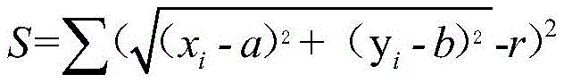
(1)假设圆的方程如下式所示:(1) Suppose the equation of a circle is as follows:

上式中,(a,b)为圆心坐标,r为圆半径。In the above formula, (a, b) is the coordinates of the center of the circle, and r is the radius of the circle.
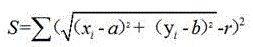
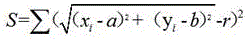
则拟合出的圆应满足使得各个边缘点集中各个边缘点(x i ,y i )的到曲线距离的平方和S最小:Then the fitted circle should meet the requirement that the sum S of the squares of the distances from each edge point ( xi , y i ) to the curve in each edge point set is the smallest:
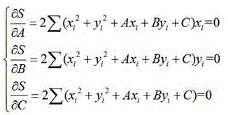
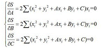
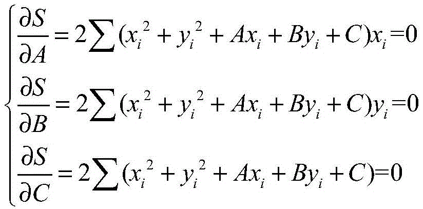
(2)令A=-2a,B=-2b,C=a2+b2-r2;要使S最小,分别对A、B、C求偏导得到如下结果:(2) Let A=-2a, B=-2b, C=a 2 +b 2 -r 2 ; to minimize S, calculate partial derivatives for A, B, and C respectively to obtain the following results:
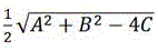
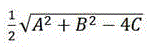
(3)求解上式得到:拟合圆的圆心坐标(a,b)为
本发明还包括一种基于点云模型的预制构件预留孔的可视化方法,该可视化方法包括如下步骤:The present invention also includes a visualization method for reserved holes of prefabricated components based on a point cloud model, the visualization method comprising the following steps:
S01:采用如前述的基于点云的预制构件预留孔的精度检测方法中步骤S1-S2的相同步骤生成预制构件各个结构面的单面点云。S01: Using the same steps as steps S1-S2 in the aforementioned point cloud-based accuracy detection method for prefabricated component reserved holes to generate a single-sided point cloud of each structural surface of the prefabricated component.
S02:对各个结构面的单面点云进而点云配准,生成预制构件对应的三维模型。S02: Register the single-sided point cloud of each structural surface and then point cloud to generate a 3D model corresponding to the prefabricated component.
S03:采用如前述的基于点云的预制构件预留孔的精度检测方法中步骤S3-S5的相同步骤识别出每个单面点云中对应各个预留孔的多个点团。S03: Using the same steps as steps S3-S5 in the aforementioned point cloud-based accuracy detection method for reserved holes in prefabricated components to identify multiple point clusters corresponding to each reserved hole in each single-sided point cloud.
S04:将点团中的各个点的颜色修改为与三维模型中相近区域具有高对比度的标记色,并将点团映射回三维模型,进而使得各个预留孔在三维模型中可视化。S04: Modify the color of each point in the point cluster to a marked color with high contrast with the adjacent area in the 3D model, and map the point cluster back to the 3D model, so that each reserved hole can be visualized in the 3D model.
本发明还包括一种基于点云的预制构件预留孔的精度检测系统,其包括存储器、处理器以及存储在存储器上并可在处理器上运行的计算机程序,处理器执行计算机程序时,实现如前述的基于点云的预制构件预留孔的精度检测方法的步骤;进而输出预制构件中各个预留孔精度的合格与否的判定结果。The present invention also includes a point cloud-based accuracy detection system for reserved holes in prefabricated components, which includes a memory, a processor, and a computer program stored on the memory and operable on the processor. When the processor executes the computer program, the As in the steps of the method for detecting the accuracy of reserved holes in prefabricated components based on point clouds; and then output the judgment results of whether the precision of each reserved hole in the prefabricated components is qualified or not.
作为本发明进一步的改进,精度检测系统包括:BIM模型存储模块、单面点云生成模块、二值化轮廓图生成模块、预留孔识别模块、点团提取模块、预留孔参数计算模块,以及参数比对模块。As a further improvement of the present invention, the accuracy detection system includes: a BIM model storage module, a single-sided point cloud generation module, a binary contour map generation module, a reserved hole identification module, a point cluster extraction module, and a reserved hole parameter calculation module, and a parameter comparison module.
其中,BIM模型存储模块用于存储待检测的预制构件的BIM模型,BIM模型中包含预制构件各结构面中对应的各个预留孔的结构参数。Wherein, the BIM model storage module is used to store the BIM model of the prefabricated component to be detected, and the BIM model includes the structural parameters of the corresponding reserved holes in each structural surface of the prefabricated component.
单面点云生成模块用于根据获取到的深度相机采集信息,生成待检测的预制构件中任意结构面的单面点云。The single-sided point cloud generation module is used to generate a single-sided point cloud of any structural surface in the prefabricated component to be detected according to the obtained information collected by the depth camera.
二值化轮廓图生成模块,其用于对生成的单面点云依次进行投影、图像处理操作。进而得到一张轮廓平滑清晰的用于区分预制构件中预留孔与实体的二值化轮廓图。二值化轮廓图中的各个像素点与单面点云中的各个点间具有一一对应的映射关系。The binarized contour map generation module is used to sequentially perform projection and image processing operations on the generated single-sided point cloud. Then a binarized contour map with smooth and clear contours for distinguishing reserved holes and entities in prefabricated components is obtained. There is a one-to-one mapping relationship between each pixel point in the binarized contour map and each point in the single-plane point cloud.
预留孔识别模块用于通过霍夫圆检测识别出所述二值化轮廓图中预留孔对应的各个圆形区域。The reserved hole identification module is used to identify each circular area corresponding to the reserved hole in the binary contour map through Hough circle detection.
点团提取模块用于根据二值化轮廓图中预留孔对应的各个圆形区域;从单面点云中提取出对应各个预留孔的各个点团。The point group extraction module is used to extract each point group corresponding to each reserved hole from the single-plane point cloud according to each circular area corresponding to the reserved hole in the binarized contour map.
预留孔参数计算模块用于提取出各个点团边缘处的各个点,构成多个边缘点集。再采用最小二乘法对每个边缘点集进行拟合,并计算出各个拟合圆的圆心坐标和半径。各个拟合圆的圆心坐标和半径即为检测出的各个预留孔的孔参数。The reserved hole parameter calculation module is used to extract each point at the edge of each point cluster to form multiple edge point sets. Then use the least square method to fit each edge point set, and calculate the center coordinates and radius of each fitted circle. The center coordinates and radii of each fitted circle are the detected hole parameters of each reserved hole.
参数比对模块,其用于将检测出的各个预留孔的孔参数与BIM模型中对应结构面中包含的各个预留孔的结构参数进行对比,进而判断待检测的预制构件是否合格。The parameter comparison module is used to compare the detected hole parameters of each reserved hole with the structural parameters of each reserved hole included in the corresponding structural surface in the BIM model, and then judge whether the prefabricated component to be detected is qualified.
本发明还包括一种基于点云的预制构件预留孔的精度检测设备,该精度检测设备包括深度相机和数据处理机构。深度相机用于对待检测的预制构件的各个结构面进行扫描。数据处理机构采用如前述的基于点云的预制构件预留孔的精度检测系统对应的产品。数据处理机构获取深度相机的扫描数据,进而根据对扫描数据的分析与判断,输出对应预制构件的预留孔精度的检测结果。The present invention also includes an accuracy detection device for reserved holes of prefabricated components based on point cloud, and the accuracy detection device includes a depth camera and a data processing mechanism. The depth camera is used to scan the various structural surfaces of the prefabricated components to be inspected. The data processing organization adopts the product corresponding to the precision detection system for reserved holes of prefabricated components based on point cloud as mentioned above. The data processing mechanism obtains the scanning data of the depth camera, and then outputs the detection result corresponding to the precision of the reserved hole of the prefabricated component according to the analysis and judgment of the scanning data.
本发明提供的技术方案,具有如下有益效果:The technical scheme provided by the invention has the following beneficial effects:
本发明提出的一种基于点云的预制构件预留孔的精度检测方法基于包含丰富信息的点云对预制构件的预留孔洞进行识别检测。检测过程先将三维点云转化为二维的二值化图,识别出其中孔洞区域,最后再将识别结果映射到三维点云中进行预留孔参数的精准测量。这种检测方法采用端到端的预留孔识别策略,完整的实现了从输入点云到输出带识别结果映射的点云的过程。其中,识别出的预留孔洞的数量、位置和尺寸信息可以直接与BIM设计模型进行对比测试,判断预制构件是否合格,同时识别出的结果也可以直接与BIM模型进行配准融合,实现检测结果可视化。A point cloud-based accuracy detection method for reserved holes of prefabricated components proposed by the present invention identifies and detects the reserved holes of prefabricated components based on point clouds containing rich information. The detection process first converts the 3D point cloud into a 2D binary image, identifies the hole area, and finally maps the recognition result to the 3D point cloud for accurate measurement of the reserved hole parameters. This detection method adopts an end-to-end reserved hole recognition strategy, and completely realizes the process from input point cloud to output point cloud with recognition result mapping. Among them, the number, position and size information of the identified reserved holes can be directly compared with the BIM design model to judge whether the prefabricated components are qualified. At the same time, the identified results can also be directly registered and fused with the BIM model to realize the detection results visualization.
本发明提出的基于点云的预制构件预留孔的精度检测方法相对现有的人工检测方法而言,可以实现更高精度的检测,检测效率也明显提升。该方案相对图像识别的检测方法而言,可以克服环境和图像质量等因素对检测结果的影响,具有更高的可靠性。该检测方法属于一种完全数字化的检测方法,打破了传统物理检测方法的瓶颈,实现质量检测环节无纸化、智能化、可视化。其应用场景广泛,除了日常检测环节,也可应用与产品溯源环节的数据存档和展示等。Compared with the existing manual detection method, the point cloud-based precision detection method for reserved holes of prefabricated components proposed by the present invention can achieve higher precision detection, and the detection efficiency is also significantly improved. Compared with the detection method of image recognition, this scheme can overcome the influence of factors such as environment and image quality on the detection result, and has higher reliability. This detection method belongs to a completely digital detection method, which breaks the bottleneck of the traditional physical detection method and realizes paperless, intelligent and visualized quality inspection. It has a wide range of application scenarios. In addition to daily testing, it can also be used for data archiving and display in product traceability.
附图说明Description of drawings
附图用来提供对本发明的进一步理解,并且构成说明书的一部分,与本发明的实施例一起用于解释本发明,并不构成对本发明的限制。在附图中:The accompanying drawings are used to provide a further understanding of the present invention, and constitute a part of the description, and are used together with the embodiments of the present invention to explain the present invention, and do not constitute a limitation to the present invention. In the attached picture:
图1为本发明实施例1中提供的一种基于点云的预制构件预留孔的精度检测方法的步骤流程图。Fig. 1 is a flow chart of the steps of a method for detecting the accuracy of reserved holes in prefabricated components based on point clouds provided in Embodiment 1 of the present invention.
图2为本发明实施例1中二值化轮廓图生成方法的流程图。FIG. 2 is a flow chart of a method for generating a binarized contour map in Embodiment 1 of the present invention.
图3为本发明实施例1中边缘点集中包含的各个边缘点的搜索方法的步骤流程图。FIG. 3 is a flow chart of the steps of the search method for each edge point included in the edge point set in Embodiment 1 of the present invention.
图4为本发明实施例2中提供的一种基于点云模型的预制构件预留孔的可视化方法的步骤流程图。FIG. 4 is a flow chart of the steps of a method for visualizing reserved holes of prefabricated components based on a point cloud model provided in Embodiment 2 of the present invention.
图5为本发明实施例3中提供的一种基于点云的预制构件预留孔的精度检测系统的系统框架图。Fig. 5 is a system frame diagram of a point cloud-based accuracy detection system for reserved holes of prefabricated components provided in Embodiment 3 of the present invention.
图6为本发明实施例4中提供的基于点云的预制构件预留孔的精度检测设备的框架图。Fig. 6 is a frame diagram of a point cloud-based accuracy detection device for reserved holes of prefabricated components provided in Embodiment 4 of the present invention.
图7为验证试验中测试样本1的霍夫圆检测识别结果。Fig. 7 shows the Hough circle detection and recognition results of test sample 1 in the verification test.
图8为验证试验中测试样本2的霍夫圆检测识别结果。Fig. 8 shows the Hough circle detection and recognition results of test sample 2 in the verification test.
图9为验证试验中测试样本3的霍夫圆检测识别结果。FIG. 9 shows the Hough circle detection and recognition results of test sample 3 in the verification test.
图10为验证试验中测试样本4的霍夫圆检测识别结果。Fig. 10 shows the Hough circle detection and recognition results of test sample 4 in the verification test.
图11为验证试验中测试样本5的霍夫圆检测识别结果。Fig. 11 shows the Hough circle detection and recognition results of test sample 5 in the verification test.
图12为验证试验中测试样本6的霍夫圆检测识别结果。Fig. 12 shows the Hough circle detection and recognition results of test sample 6 in the verification test.
图13为实施例2提供中可视化方法的实施案例。FIG. 13 is an implementation example of the visualization method provided in Embodiment 2.
具体实施方式Detailed ways
为了使本发明的目的、技术方案及优点更加清楚明白,以下结合附图及实施例,对本发明进行进一步详细说明。应当理解,此处所描述的具体实施例仅用以解释本发明,并不用于限定本发明。In order to make the object, technical solution and advantages of the present invention clearer, the present invention will be further described in detail below in conjunction with the accompanying drawings and embodiments. It should be understood that the specific embodiments described here are only used to explain the present invention, not to limit the present invention.
实施例1Example 1
本实施例提供一种基于点云的预制构件预留孔的精度检测方法,其用于对装配式建筑预制件工厂生成的产品中的各个预留孔进行精度检测,进而判断加工出的预制构件是否合格。This embodiment provides a method for detecting the accuracy of reserved holes in prefabricated components based on point clouds, which is used to detect the accuracy of each reserved hole in the product generated by the prefabricated building factory, and then judge the processed prefabricated components Eligibility.
本实施例提供的方法主要是通过深度相机来采集预制构件对应的点云,相对于传统的图像识别而言,点云中的点包含了丰富的信息,包括三维坐标X,Y,Z、颜色、分类值、强度值、时间等等。点云可以将现实世界“原子化”,通过高精度的点云数据可以还原现实世界。因此,本实施例利用点云数据来对预制构件中的孔洞进行检测时,可以减轻外界环境、复杂光线等对测试结果的影响,测试过程中还可以利用算法对预制构件进行三维立体成像,进而在实现孔洞检测的同时对检测结果进行可视化。The method provided in this embodiment mainly collects the point cloud corresponding to the prefabricated component through the depth camera. Compared with the traditional image recognition, the points in the point cloud contain rich information, including three-dimensional coordinates X, Y, Z, color , categorical values, intensity values, time, and so on. Point cloud can "atomize" the real world, and the real world can be restored through high-precision point cloud data. Therefore, when this embodiment uses point cloud data to detect holes in prefabricated components, it can reduce the impact of external environment, complex light, etc. Visualize the detection results while implementing hole detection.
具体地 ,如图1所示,该预制构件预留孔的精度检测方法包括如下步骤:Specifically, as shown in Figure 1, the accuracy detection method for the reserved holes of the prefabricated component includes the following steps:
S1:利用深度相机对待测预制构件的各个结构面进行扫描,进而得到每个结构面对应原始彩色图像和原始深度图。S1: Use the depth camera to scan each structural surface of the prefabricated component to be tested, and then obtain the original color image and original depth map corresponding to each structural surface.
S2:基于原始彩色图像和原始深度图生成所述预制构件对应结构面的单面点云。S2: Generate a single-sided point cloud of the corresponding structural surface of the prefabricated component based on the original color image and the original depth map.
本实施例在用深度相机获取构件点云的时候不可避免的要拍摄到大量背景数据,包括工厂、堆场复杂环境以及地面信息。因此在进行预留孔精度检测之前,本方案可以采用优化的区域生长算法将这些背景数据分割出来,只保留目标物优化。这种处理方式可以提高准确度、减少处理时间和内存消耗。In this embodiment, it is inevitable to capture a large amount of background data when the depth camera is used to obtain the point cloud of the component, including the complex environment of the factory, the yard, and the ground information. Therefore, before the accuracy detection of the reserved holes, this program can use the optimized region growing algorithm to segment these background data, and only keep the target object for optimization. This approach improves accuracy and reduces processing time and memory consumption.
S3:对单面点云进行投影并对投影图进行像素优化,进而得到一张用于区分预制构件中预留孔与实体的二值化图。二值化图中的各个像素点与单面点云中的各个点间具有一一对应的映射关系。S3: Project the single-sided point cloud and optimize the pixels of the projected image to obtain a binary image for distinguishing between reserved holes and entities in prefabricated components. There is a one-to-one mapping relationship between each pixel point in the binarized image and each point in the single-plane point cloud.
由于投影图的像素与点云中的点团是一一对应的关系,使用投影图处理比使用采集的图片处理会有极高的优势。首先,使用投影图可以保证图片无畸变,其次使用投影图可以将识别到的结果映射回点云,形成一个完整的回路。Since there is a one-to-one correspondence between the pixels of the projection image and the point clusters in the point cloud, using the projection image processing has a very high advantage over using the collected image processing. First of all, using the projection map can ensure that the picture is not distorted, and secondly, using the projection map can map the recognized results back to the point cloud to form a complete loop.
其中,如图2所示,二值化图的生成方法包括如下步骤:Wherein, as shown in Figure 2, the generation method of the binary image includes the following steps:
S31:将单面点云中的所有点投影至XY平面,隐藏各点在Z轴上的深度信息;得到一张对应的投影图。单面点云的投影方法如下:S31: Project all the points in the single-plane point cloud to the XY plane, hide the depth information of each point on the Z axis; obtain a corresponding projection map. The projection method of single-sided point cloud is as follows:
首先,使用主成分分析技术计算出单面点云对应平面的平面法向量。然后,对计算出的法向量方向采用最小代价生成树进行调整,并使得单面点云中的各个点的Z轴与平面法向量平行。最后,将所有点投射到XY平面;即:隐藏各点的坐标信息中Z坐标的数据。First, the plane normal vector of the plane corresponding to the single-plane point cloud is calculated by using the principal component analysis technique. Then, the calculated direction of the normal vector is adjusted using the minimum cost spanning tree, and the Z axis of each point in the single-plane point cloud is parallel to the plane normal vector. Finally, project all points to the XY plane; that is, hide the Z coordinate data in the coordinate information of each point.
S32:对投影图中的所有像素点按照预设的步长进行网格划分,将划分出的每个网格中的各个像素点的RGB值设为网格内所有像素点的RGB均值。S32: Carry out grid division for all pixels in the projection image according to a preset step size, and set the RGB value of each pixel in each divided grid as the RGB average value of all pixels in the grid.
S33:对上步骤的投影图中的像素点进行中位值滤波处理,得到补全后的投影图。S33: Perform median filtering processing on the pixels in the projection image in the previous step to obtain a completed projection image.
中位值滤波处理过程中,将每一个像素点的像素值设置为该像素点某邻域窗口内的所有像素点像素的中值,进而调整投影图中部分颜色信息丢失的像素点的像素值,将投影图优化为补全后的投影图。In the process of median value filtering, the pixel value of each pixel is set as the median value of all pixels in a certain neighborhood window of the pixel, and then the pixel value of some pixels whose color information is lost in the projection image is adjusted , optimize the projection graph to the completed projection graph.
S34:根据原始颜色图像中预留孔与实体部分的像素值差异设定阈值,对补全后的投影图进行二值化处理,得到一张二值化图像。S34: Set a threshold according to the pixel value difference between the reserved hole and the solid part in the original color image, and perform binarization processing on the completed projected image to obtain a binarized image.
S35:基于每个像素点与相邻像素点的像素值差异,对二值化图像中的各个像素点进行除杂操作。S35: Perform an impurity removal operation on each pixel in the binarized image based on the pixel value difference between each pixel and adjacent pixels.
除杂过程中,依次将二值化图像中的每个像素点作为中心像素点,并执行如下操作:During the impurity removal process, each pixel in the binarized image is taken as the central pixel in turn, and the following operations are performed:
(ⅰ)获取中心像素点的8个相邻像素点的像素值。(i) Obtain the pixel values of 8 adjacent pixels of the central pixel.
(ⅱ)统计与中心像素点的像素值相同的相邻像素点的数量n。(ii) Count the number n of adjacent pixels with the same pixel value as the center pixel.
(ⅲ)判断n与一个预设的除杂阈值N之间的关系:(1)当n≥N时,保留当前像素点的像素值;(2)当n<N时,对当前像素点的像素值进行反转。(iii) Judging the relationship between n and a preset impurity removal threshold N: (1) when n≥N, keep the pixel value of the current pixel; (2) when n<N, the current pixel Pixel values are inverted.
在本实施例中,二值化后的图像中理论上就只有两种不同区域,一是对应预制构件中实体部分的区域,另一部分为对应预制构件中孔洞部分(既包括预留孔,也可能包括开槽、镂空等结构)的区域。因此在转为二值化图像后,对应不同区域的图像应当是边界分明的。但是,由于二值化图像是通过原始彩色图像处理得到的,原始彩色图像的图像质量可能会造成二值化图像中部分像素点的灰度存在误差,即出现一些零散的“噪点”。除杂操作的目标即是用于去除这些明显错误的噪点;对这些像素点的像素值进行“纠正”。In this embodiment, there are theoretically only two different areas in the binarized image, one is the area corresponding to the solid part of the prefabricated component, and the other is the corresponding hole part in the prefabricated component (both reserved holes and Areas that may include structures such as slots, hollows, etc.). Therefore, after converting to a binarized image, images corresponding to different regions should have clear boundaries. However, since the binarized image is obtained by processing the original color image, the image quality of the original color image may cause errors in the grayscale of some pixels in the binarized image, that is, some scattered "noises". The goal of the decluttering operation is to remove these obviously wrong noise points; to "correct" the pixel values of these pixels.
S36:依次采用开运算和闭运算对除杂后的二值化图像进行腐蚀和膨胀处理;使得二值化图的轮廓平滑清晰。S36: Carry out erosion and dilation processing on the binarized image after impurity removal by sequentially adopting an opening operation and a closing operation; so that the contour of the binarized image is smooth and clear.
对处理后的二值化图片进行先腐蚀后膨胀——即为开运算;相对的反过来就是——闭运算。这两类运算目的,是为了消除原图拍摄时产生的轮廓(内/外)毛刺、尖端、或者噪音;开运算主要是为了腐蚀掉不关心的轮廓尖端;很明显通过腐蚀后再膨胀,轮廓将变得更加圆滑,并消除了尖端。The processed binarized image is first corroded and then expanded - that is, the opening operation; the opposite is the closing operation. The purpose of these two types of operations is to eliminate the contour (inner/outer) burrs, tips, or noise generated when the original image is taken; the open operation is mainly to corrode the contour tip that is not concerned; it is obvious that after erosion, the contour will expand. will become more rounded and eliminate the tip.
S4:先采用Canny算子对上步骤的二值化图进行边缘检测,得到所需的二值化轮廓图。再采用霍夫圆检测识别出所述二值化轮廓图中预留孔对应的各个圆形区域。S4: First use the Canny operator to perform edge detection on the binary image in the previous step to obtain the required binary image. Then Hough circle detection is used to identify each circular area corresponding to the reserved hole in the binary contour map.
在本实施例的实际应用中,由于同种类型的预制构件中预留孔洞的大小和位置都是相对固定的,所以可以按照构件的类型来设定霍夫圆识别的参数。进而提高识别的精度和速度。具体地,可以采用霍夫圆检测识别构件孔洞。In the practical application of this embodiment, since the size and position of the reserved holes in the same type of prefabricated components are relatively fixed, the parameters for Hough circle identification can be set according to the type of component. This improves the accuracy and speed of recognition. Specifically, Hough circle detection can be used to identify component holes.
S5:基于二值化图中各像素点与单面点云中各点间的映射关系,根据上步骤的识别结果从单面点云中选出用于表征各个预留孔的多个点团。S5: Based on the mapping relationship between each pixel point in the binarized image and each point in the single-sided point cloud, select multiple point clusters from the single-sided point cloud to represent each reserved hole according to the recognition results of the previous step .
S6:根据各个预留孔的点团计算出每个预留孔的圆心和半径,具体计算过程如下:S6: Calculate the center and radius of each reserved hole according to the point clusters of each reserved hole. The specific calculation process is as follows:
S61:采用点云边缘算法提取出各个点团边缘处的各个点,构成多个边缘点集。其中如图3所示,边缘点集中包含的各个边缘点的搜索方法如下:S61: Using a point cloud edge algorithm to extract each point at the edge of each point cluster to form a plurality of edge point sets. As shown in Figure 3, the search method of each edge point contained in the edge point set is as follows:
(1)对于任一点p,设定滚动圆半径a,在点云内搜索到距离p点2α内的所有点,记为点集Q。(1) For any point p, set the radius a of the rolling circle, search for all points within 2α from point p in the point cloud, and record it as point set Q.
(2)选取点集Q中任意一点p1 (x1,y1),根据p和p1两点的坐标和滚动圆半径α,计算出过p、p1两点且半径为α的两个圆的圆心坐标,分别记为p2、p3。(2) Select any point p 1 (x 1 , y 1 ) in point set Q, and calculate two points with radius α passing through p and p 1 according to the coordinates of p and p 1 and the rolling circle radius α. The coordinates of the centers of the circles are denoted as p 2 and p 3 respectively.
(3)计算点集Q中除点p1外,剩余点分别到p2、p3的距离,若所有点到p2和p3的距离均大于α,则表明p点为边缘点。(3) Calculate the distances from point set Q except point p1 to p2 and p3 respectively. If the distances from all points to p2 and p3 are greater than α, point p is an edge point.
(4)若剩余的点到p2或p3的距离不全都大于α;则将点集Q内所有点轮换作为p1点;并判断是否存在某一点满足(2)(3)条件:是则表明该点为边缘点,终止该点的判断,判断下一点。(4) If the distances from the remaining points to p 2 or p 3 are not all greater than α; then rotate all points in the point set Q as point p 1 ; and judge whether there is a point that satisfies (2) (3) conditions: Yes Then it indicates that the point is an edge point, the judgment of this point is terminated, and the next point is judged.
(5)若Q中所有近邻点中均不存在满足(2)、(3)条件的p1点,则表明p点为非边缘点。(5) If there is no point p 1 satisfying the conditions (2) and (3) among all the neighboring points in Q, it indicates that point p is a non-edge point.
S62:采用最小二乘法对每个边缘点集进行拟合,并计算出各个拟合圆的圆心坐标和半径。根据边缘点集拟合出所需的拟合圆的过程如下:S62: Use the least square method to fit each edge point set, and calculate the center coordinates and radii of each fitted circle. The process of fitting out the required fitting circle according to the edge point set is as follows:
(1)假设圆的方程如下式所示:(1) Suppose the equation of a circle is as follows:

上式中,(a,b)为圆心坐标,r为圆半径。In the above formula, (a, b) is the coordinates of the center of the circle, and r is the radius of the circle.
则拟合出的圆应满足使得各个边缘点集中各个边缘点(x i ,y i )的到曲线距离的平方和S最小:Then the fitted circle should meet the requirement that the sum S of the squares of the distances from each edge point ( xi , y i ) to the curve in each edge point set is the smallest:
(2)令A=-2a,B=-2b,C=a2+b2-r2;要使S最小,分别对A、B、C求偏导得到如下结果:(2) Let A=-2a, B=-2b, C=a 2 +b 2 -r 2 ; to minimize S, calculate partial derivatives for A, B, and C respectively to obtain the following results:
(3)求解上式得到:拟合圆的圆心坐标(a,b)为
S63: 分析边界获取目标的几何参量(x,y,0)和r;再计算(x,y,0)*投影矩阵的逆反投影得到(x,y,z);S63: Analyze the boundary to obtain the geometric parameters (x, y, 0) and r of the target; then calculate the inverse back projection of (x, y, 0)*projection matrix to obtain (x, y, z);
S7:将计算出的各个拟合圆的圆心坐标和半径与预制构件BIM模型中各个预留孔的标准参数进行比对,进而判断预制构件是否合格。具体地,本实施例可以提取BIM模型点云,通过点云配准技术将目标点云与BIM模型点云移至一个坐标系下,计算圆心之间的偏差是否符合预留孔偏差标准。S7: Compare the calculated center coordinates and radii of each fitting circle with the standard parameters of each reserved hole in the prefabricated component BIM model, and then judge whether the prefabricated component is qualified. Specifically, this embodiment can extract the point cloud of the BIM model, move the target point cloud and the point cloud of the BIM model into a coordinate system through the point cloud registration technology, and calculate whether the deviation between the center of the circle meets the deviation standard of the reserved hole.
本实施例中提供的预制构件孔精度检测方法,主要基于点云进行检测。并在检测过程中先将点云映射到二维平面,在二维投影图中进行孔洞识别,进而大幅降低预留孔洞的识别过程的数据运算量。在进行孔洞参数运算时,又重新将孔洞映射回三维的点云中进行操作,进而提高最终计算出的孔洞的位置和尺寸的精度;保障最终检测结果的精准性。The method for detecting the hole accuracy of prefabricated components provided in this embodiment is mainly based on point cloud detection. In the detection process, the point cloud is first mapped to a two-dimensional plane, and hole recognition is performed in the two-dimensional projection map, thereby greatly reducing the amount of data calculation in the recognition process of reserved holes. When calculating the hole parameters, the hole is remapped back to the three-dimensional point cloud for operation, thereby improving the accuracy of the position and size of the finally calculated hole; ensuring the accuracy of the final detection result.
实施例2Example 2
在实施例1的基础上,本实施例进一步提供一种基于点云模型的预制构件预留孔的可视化方法,如图4所示,该可视化方法包括如下步骤:On the basis of Embodiment 1, this embodiment further provides a visualization method for reserved holes of prefabricated components based on a point cloud model. As shown in FIG. 4, the visualization method includes the following steps:
S01:采用如实施例1的基于点云的预制构件预留孔的精度检测方法中步骤S1-S2的相同步骤生成预制构件各个结构面的单面点云。S01: Use the same steps as in steps S1-S2 in the method for detecting the accuracy of reserved holes in prefabricated components based on point clouds in Embodiment 1 to generate a single-sided point cloud of each structural surface of the prefabricated component.
S02:对各个结构面的单面点云进而点云配准,生成预制构件对应的三维模型。S02: Register the single-sided point cloud of each structural surface and then point cloud to generate a 3D model corresponding to the prefabricated component.
S03:采用如实施例1的基于点云的预制构件预留孔的精度检测方法中步骤S3-S5的相同步骤识别出每个单面点云中对应各个预留孔的多个点团。S03: Use the same steps as steps S3-S5 in the method for detecting the accuracy of reserved holes in prefabricated components based on point clouds in Example 1 to identify multiple point clusters corresponding to each reserved hole in each single-sided point cloud.
S04:将点团中的各个点的颜色修改为与三维模型中相近区域具有高对比度的标记色,并将点团映射回三维模型,进而使得各个预留孔在三维模型中可视化。S04: Modify the color of each point in the point cluster to a marked color with high contrast with the adjacent area in the 3D model, and map the point cluster back to the 3D model, so that each reserved hole can be visualized in the 3D model.
本实施例利用点云来对预制构件进行三维建模,并对实施例1中检测出来的点团来对三维模型中的各个孔洞进行标记。例如,当三维模型中的预制构件呈水泥灰的颜色时,可以将表征孔洞的部分点团的像素点调整为红色,从而使得预制构件三维模型中的孔洞部分更加醒目;便于技术人员观察和分析。In this embodiment, the point cloud is used to carry out three-dimensional modeling of the prefabricated component, and the point clusters detected in embodiment 1 are used to mark each hole in the three-dimensional model. For example, when the prefabricated component in the 3D model is in the color of cement gray, the pixel points representing some point clusters representing holes can be adjusted to red, so that the hole part in the 3D model of the prefabricated component is more eye-catching; it is convenient for technicians to observe and analyze .
实施例3Example 3
在实施例1的基础上,本实施例进一步提供了一种基于点云的预制构件预留孔的精度检测系统。该精度检测系统包括存储器、处理器以及存储在存储器上并可在处理器上运行的计算机程序。处理器执行计算机程序时,实现如实施例1中基于点云的预制构件预留孔的精度检测方法的步骤;进而输出预制构件中各个预留孔精度的合格与否的判定结果。On the basis of Embodiment 1, this embodiment further provides a point cloud-based accuracy detection system for reserved holes of prefabricated components. The accuracy detection system includes a memory, a processor, and a computer program stored in the memory and operable on the processor. When the processor executes the computer program, it realizes the steps of the method for detecting the accuracy of the reserved holes of the prefabricated component based on the point cloud in Embodiment 1; and then outputs the judgment result of whether the accuracy of each reserved hole in the prefabricated component is qualified or not.
在该精度检测系统的实际部署中,计算机设备可以是能够执行程序的智能手机、平板电脑、笔记本电脑、台式计算机、机架式服务器、刀片式服务器、塔式服务器或机柜式服务器(包括独立的服务器,或者多个服务器所组成的服务器集群)等。本实施例的计算机设备至少包括但不限于:可通过系统总线相互通信连接的存储器、处理器。In the actual deployment of the accuracy detection system, the computer equipment can be a smart phone, a tablet computer, a notebook computer, a desktop computer, a rack server, a blade server, a tower server or a cabinet server (including a stand-alone server, or a server cluster composed of multiple servers), etc. The computer device in this embodiment at least includes but is not limited to: a memory and a processor that can be communicatively connected to each other through a system bus.
本实施例中,存储器(即可读存储介质)包括闪存、硬盘、多媒体卡、卡型存储器(例如,SD或DX存储器等)、随机访问存储器(RAM)、静态随机访问存储器(SRAM)、只读存储器(ROM)、电可擦除可编程只读存储器(EEPROM)、可编程只读存储器(PROM)、磁性存储器、磁盘、光盘等。在一些实施例中,存储器可以是计算机设备的内部存储单元,例如该计算机设备的硬盘或内存。在另一些实施例中,存储器也可以是计算机设备的外部存储设备,例如该计算机设备上配备的插接式硬盘,智能存储卡(Smart Media Card ,SMC),安全数字(Secure Digital ,SD)卡,闪存卡(Flash Card)等。当然,存储器还可以既包括计算机设备的内部存储单元也包括其外部存储设备。本实施例中,存储器通常用于存储安装于计算机设备的操作系统和各类应用软件等。此外,存储器还可以用于暂时地存储已经输出或者将要输出的各类数据。In this embodiment, the memory (that is, the readable storage medium) includes a flash memory, a hard disk, a multimedia card, a card-type memory (for example, SD or DX memory, etc.), random access memory (RAM), static random access memory (SRAM), Read Memory (ROM), Electrically Erasable Programmable Read Only Memory (EEPROM), Programmable Read Only Memory (PROM), Magnetic Memory, Magnetic Disk, Optical Disk, etc. In some embodiments, the memory may be an internal storage unit of the computer device, such as a hard disk or internal memory of the computer device. In other embodiments, the memory may also be an external storage device of the computer device, such as a plug-in hard disk equipped on the computer device, a smart memory card (Smart Media Card, SMC), a secure digital (Secure Digital, SD) card , Flash Card (Flash Card) and so on. Of course, the storage may also include both the internal storage unit of the computer device and its external storage device. In this embodiment, the memory is usually used to store the operating system and various application software installed in the computer equipment. In addition, the memory can also be used to temporarily store various types of data that have been output or will be output.
处理器在一些实施例中可以是中央处理器(Central Processing Unit,CPU)、控制器、微控制器、微处理器、或其他数据处理芯片。该处理器通常用于控制计算机设备的总体操作。本实施例中,处理器用于运行存储器中存储的程序代码或者处理数据,该处理器执行计算机程序时实现如实施例1中的基于点云的预制构件预留孔的精度检测方法的步骤。In some embodiments, the processor may be a central processing unit (Central Processing Unit, CPU), a controller, a microcontroller, a microprocessor, or other data processing chips. The processor is typically used to control the overall operation of the computer device. In this embodiment, the processor is used to run the program code or process data stored in the memory, and when the processor executes the computer program, it realizes the steps of the method for detecting the accuracy of reserved holes of prefabricated components based on point cloud as in Embodiment 1.
具体地,如图5所示,按照功能进行划分,精度检测系统包括:BIM模型存储模块、单面点云生成模块、二值化轮廓图生成模块、预留孔识别模块、点团提取模块、预留孔参数计算模块,以及参数比对模块。Specifically, as shown in Figure 5, the accuracy detection system is divided according to the function, including: BIM model storage module, single-sided point cloud generation module, binary contour map generation module, reserved hole recognition module, point blob extraction module, Reserved hole parameter calculation module, and parameter comparison module.
其中,BIM模型存储模块用于存储待检测的预制构件的BIM模型,BIM模型中包含预制构件各结构面中对应的各个预留孔的结构参数。Wherein, the BIM model storage module is used to store the BIM model of the prefabricated component to be detected, and the BIM model includes the structural parameters of the corresponding reserved holes in each structural surface of the prefabricated component.
单面点云生成模块用于根据获取到的深度相机采集信息,生成待检测的预制构件中任意结构面的单面点云。The single-sided point cloud generation module is used to generate a single-sided point cloud of any structural surface in the prefabricated component to be detected according to the obtained information collected by the depth camera.
二值化轮廓图生成模块,其用于对生成的单面点云依次进行投影、网格化、RGB均值操作、中位值滤波、二值化处理、像素点除杂,以及腐蚀和膨胀操作。进而得到一张轮廓平滑清晰的用于区分预制构件中预留孔与实体的二值化轮廓图。二值化轮廓图中的各个像素点与单面点云中的各个点间具有一一对应的映射关系。Binarized contour map generation module, which is used to sequentially perform projection, gridding, RGB mean value operation, median value filtering, binarization processing, pixel point removal, and erosion and expansion operations on the generated single-sided point cloud . Then a binarized contour map with smooth and clear contours for distinguishing reserved holes and entities in prefabricated components is obtained. There is a one-to-one mapping relationship between each pixel point in the binarized contour map and each point in the single-plane point cloud.
预留孔识别模块用于通过霍夫圆检测识别出所述二值化轮廓图中预留孔对应的各个圆形区域。The reserved hole identification module is used to identify each circular area corresponding to the reserved hole in the binary contour map through Hough circle detection.
点团提取模块用于根据二值化轮廓图中预留孔对应的各个圆形区域;从单面点云中提取出对应各个预留孔的各个点团。The point group extraction module is used to extract each point group corresponding to each reserved hole from the single-plane point cloud according to each circular area corresponding to the reserved hole in the binarized contour map.
预留孔参数计算模块用于先采用Alpha Shapes算法提取出各个点团边缘处的各个点,构成多个边缘点集。再采用最小二乘法对每个边缘点集进行拟合,并计算出各个拟合圆的圆心坐标和半径。各个拟合圆的圆心坐标和半径即为检测出的各个预留孔的孔参数。The reserved hole parameter calculation module is used to first extract each point at the edge of each point cluster by using the Alpha Shapes algorithm to form multiple edge point sets. Then use the least square method to fit each edge point set, and calculate the center coordinates and radius of each fitted circle. The center coordinates and radii of each fitted circle are the detected hole parameters of each reserved hole.
参数比对模块,其用于将检测出的各个预留孔的孔参数与BIM模型中对应结构面中包含的各个预留孔的结构参数进行对比,进而判断待检测的预制构件是否合格。The parameter comparison module is used to compare the detected hole parameters of each reserved hole with the structural parameters of each reserved hole included in the corresponding structural surface in the BIM model, and then judge whether the prefabricated component to be detected is qualified.
实施例4Example 4
本实施例提供一种基于点云的预制构件预留孔的精度检测设备,如图6所示,该精度检测设备包括位于前端的检测设备如深度相机,以及位于后端的数据处理机构。This embodiment provides an accuracy detection device for reserved holes of prefabricated components based on point cloud. As shown in FIG. 6 , the accuracy detection device includes a detection device at the front end such as a depth camera, and a data processing mechanism at the back end.
深度相机用于对待检测的预制构件的各个结构面进行扫描。The depth camera is used to scan the various structural surfaces of the prefabricated components to be inspected.
数据处理机构采用如实施例2的基于点云的预制构件预留孔的精度检测系统对应的产品。数据处理机构获取深度相机的扫描数据,进而根据对扫描数据的分析与判断,输出对应预制构件的预留孔精度的检测结果。The data processing mechanism adopts the product corresponding to the point cloud-based precision detection system for reserved holes of prefabricated components as in Embodiment 2. The data processing mechanism obtains the scanning data of the depth camera, and then outputs the detection result corresponding to the precision of the reserved hole of the prefabricated component according to the analysis and judgment of the scanning data.
仿真试验simulation test
为了验证本实施例提供方法的有效性,本实施例采用实验的方法对实施例1中提供的基于点云的预制构件预留孔的精度检测方法的有效性及准确度进行验证。具体实验过程包括数据采集、预留孔数量识别检测、预留孔位置及半径偏差检测和质检结果模型的可视化展示四个步骤。试验过程中,自制构件的真实模型用于生成点云模型(目标点云),并用3D建模软件建模标准模型(标准点云类似BIM模型)。In order to verify the effectiveness of the method provided in this embodiment, this embodiment uses an experimental method to verify the validity and accuracy of the point cloud-based precision detection method for reserved holes of prefabricated components provided in embodiment 1. The specific experimental process includes four steps: data collection, identification and detection of the number of reserved holes, detection of the position and radius deviation of the reserved holes, and visual display of the quality inspection result model. During the test, the real model of self-made components is used to generate a point cloud model (target point cloud), and a standard model is modeled with 3D modeling software (standard point cloud is similar to a BIM model).
一、数据采集1. Data collection
本实验采用深度相机获取预制构件各面的质量检测数据;其中,所需的深度图像数据采用人工拍摄的方式完成。深度相机每个面拍摄3-5张深度和彩色图像,用于生成单个面点云。In this experiment, the depth camera is used to obtain the quality inspection data of each side of the prefabricated component; among them, the required depth image data is completed by manual shooting. The depth camera takes 3-5 depth and color images for each surface, which are used to generate a single surface point cloud.
二、预留孔数量识别检测2. Recognition and detection of the number of reserved holes
本实施例中设置了六个测试样本进行测试,分别对应编号YWQ1、YWQ2、YWQ10、YWQ12、YWQ13、YWQ16。其中,测试样本1中含有21个预留孔,测试样本2中含有24个预留孔,测试样本3中含有20个预留孔,测试样本4中含有21个预留孔,测试样本5中含有21个预留孔,测试样本6中含有20个预留孔。各个测试样本经本实施例中霍夫圆检测识别后的结果如图7-12所示。In this embodiment, six test samples are set for testing, corresponding to numbers YWQ1, YWQ2, YWQ10, YWQ12, YWQ13, and YWQ16 respectively. Among them, test sample 1 contains 21 reserved holes, test sample 2 contains 24 reserved holes, test sample 3 contains 20 reserved holes, test sample 4 contains 21 reserved holes, and test sample 5 contains 21 reserved holes. Contains 21 reserved holes, and test sample 6 contains 20 reserved holes. The results of each test sample identified by the Hough circle detection in this embodiment are shown in Figures 7-12.
基于图中的实验结果可以发现:测试样本1和4的检测效果较好,所有预留孔均被完整识别出来。测试样本2和5存在误检现象,出现这一现象的原因是由于预制构件3、4所处背景复杂,导致重建出来的三维模型背景噪声过多,经过点云滤波去噪处理后仍存在一定杂点,被误认为是需要识别的预留孔,导致识别数量比真实数量多,在叠加一层滤波处理后情况得到改善。测试样本3和6存在漏检现象,出现这一现象的原因是当时室外光线较为强烈,表面反光部分遮盖了孔洞所在位置。这说明本实施例提供的方法对图像的质量仍存在一定的依赖,因此应该尽量提高拍摄图片的质量和角度,避免因为光线对实验结果造成干扰。Based on the experimental results in the figure, it can be found that the detection results of test samples 1 and 4 are better, and all reserved holes are completely identified. There are false detections in test samples 2 and 5. The reason for this phenomenon is that the background noise of the reconstructed 3D model is too much due to the complex background of prefabricated components 3 and 4. Miscellaneous points are mistaken for reserved holes that need to be recognized, resulting in more recognition than the real number, and the situation is improved after adding a layer of filtering processing. Test samples 3 and 6 had missed inspections. The reason for this phenomenon was that the outdoor light was relatively strong at that time, and the reflective part of the surface covered the location of the hole. This shows that the method provided in this embodiment still has a certain dependence on the quality of the image, so the quality and angle of the captured picture should be improved as much as possible to avoid interference to the experimental results due to light.
经过大量实验,对本实施例中点云到点云的装配式建筑预制构件预留孔识别的准确度进行统计,准确精度均超过98%,相对于人工质检,实现了自动化和高准确度。After a large number of experiments, statistics are made on the accuracy of the recognition of reserved holes of prefabricated building components from point cloud to point cloud in this embodiment, and the accuracy exceeds 98%. Compared with manual quality inspection, automation and high accuracy are realized.
三、预留孔位置及半径偏差检测3. Detection of reserved hole position and radius deviation
为了验证该检测方案的鲁棒性,本实施例六种不同类型构件(分别与编号YWQ1、YWQ2、YWQ10、YWQ12、YWQ13、YWQ16类型相同)上的孔洞位置和半径偏差进行了重复性测试。每类构件检测50个。In order to verify the robustness of the detection scheme, the position and radius deviation of holes on six different types of components (respectively the same as the numbers YWQ1, YWQ2, YWQ10, YWQ12, YWQ13, and YWQ16) in this embodiment were repeatedly tested. 50 components of each type were tested.
参照国标JCJ 1预制构件预留孔尺寸允许偏差为±10mm,为进一步验证本方法检测的精确率将该实验分为三个步骤:Referring to the national standard JCJ 1, the permissible deviation of the reserved hole size of prefabricated components is ±10mm. In order to further verify the detection accuracy of this method, the experiment is divided into three steps:
(1)设置允许偏差为±5mm,本步骤目的主要是验证本实施例中方法的准确性以及可靠性。(1) The allowable deviation is set to ±5mm. The purpose of this step is mainly to verify the accuracy and reliability of the method in this embodiment.
经过7天大量的重复实验通过最小二乘拟合得到孔洞边缘后求出孔洞位置和半径,筛选出不符合偏差要求的预制构件孔洞。After a large number of repeated experiments for 7 days, the edge of the hole was obtained by least squares fitting, and then the position and radius of the hole were obtained, and the prefabricated component holes that did not meet the deviation requirements were screened out.
相较于传统的人工钢尺检查方法,本发明提供的方案的检测精度更高,因此具有很高的实用价值,可以进行推广应用。Compared with the traditional manual steel ruler inspection method, the detection accuracy of the solution provided by the invention is higher, so it has high practical value and can be popularized and applied.
(2)但考虑到机器质检可能会存在一定的失误率,比如说我们方法测量出YWQ1的孔洞13偏差为9.7mm,认定其为合格。但人工检测实际偏差为10.1mm,则该孔洞为不合格不应继续下一步使用。本实施例还在方法中添加了风险评估机制,对于偏差在0-5mm的孔洞,设置其为低风险(绿色表示);对于偏差在5-7mm的孔洞,设置其为中风险(黄色表示);对于偏差在8-10mm的孔洞,设置其为高风险(红色表示)。由于步骤1中已经验证本实施例方法的可靠性和准确度,所以对于中低风险的孔洞通常认为其是完全合格的,对于高风险区域孔洞可以在系统中释放警告,提醒质检员着重对这些构件进一步进行人工复检。(2) However, considering that there may be a certain error rate in the machine quality inspection, for example, the deviation of the hole 13 of YWQ1 measured by our method is 9.7mm, and it is considered qualified. But the actual deviation of manual detection is 10.1mm, then the hole is unqualified and should not be used in the next step. This embodiment also adds a risk assessment mechanism to the method. For holes with a deviation of 0-5mm, set it as low risk (indicated in green); for holes with a deviation of 5-7mm, set it as medium risk (indicated in yellow) ; For holes with a deviation of 8-10mm, set it as high risk (indicated in red). Since the reliability and accuracy of the method of this embodiment have been verified in step 1, it is generally considered to be fully qualified for holes with medium and low risks, and a warning can be released in the system for holes in high-risk areas to remind quality inspectors to focus on These components are further subjected to manual review.
(3)本步骤主要是对步骤(2)中筛选出来的孔洞进行人工复检,进而与本实施例提出的基于点云的预制构件预留孔的精度检测方法的检测结果对比,验证本实验方法的精确率。(3) This step is mainly to manually re-inspect the holes screened in step (2), and then compare it with the detection results of the precision detection method for reserved holes of prefabricated components based on point cloud proposed in this embodiment, to verify this experiment The accuracy of the method.
需要说明的是,由于孔洞点云数量较多,对点云进行降采样处理,减少了边缘提取时间,提高了效率。在硬件设备性能允许的前提下,本实施例还可以设置多组深度相机进行取景,以获得更准确的预留孔数量和位置以及半径偏差信息,最大限度的消除光线等因素对检测精度的影响。It should be noted that due to the large number of hole point clouds, downsampling the point clouds reduces the edge extraction time and improves the efficiency. Under the premise that the performance of the hardware device is allowed, this embodiment can also set multiple sets of depth cameras for framing, so as to obtain more accurate information on the number and position of reserved holes and radius deviation information, and eliminate the influence of light and other factors on the detection accuracy to the greatest extent. .
四、质检结果模型的可视化展示4. Visual display of quality inspection result model
将孔洞识别的结果通过投影的逆过程映射回深度学习三维重建生成的点云,输出识别成功后的点云结果。将识别出的孔洞二值化图像保留,其他部分置空。可以将像素逆映射到点云中以步长的平方倍的点团中,将这部分点团修改成红色。图13即为采用本实施例的可视化方法展示预制构件的三维模型中预留孔洞的案例。The result of hole recognition is mapped back to the point cloud generated by deep learning 3D reconstruction through the inverse process of projection, and the point cloud result after successful recognition is output. The binarized image of the identified hole is retained, and the other parts are left blank. The pixel can be inversely mapped to the point cloud with the square of the step size in the point cloud, and this part of the point group can be modified to red. Fig. 13 is a case of displaying holes reserved in a three-dimensional model of a prefabricated component using the visualization method of this embodiment.
以上所述仅为本发明的较佳实施例而已,并不用以限制本发明,凡在本发明的精神和原则之内所作的任何修改、等同替换和改进等,均应包含在本发明的保护范围之内。The above descriptions are only preferred embodiments of the present invention, and are not intended to limit the present invention. Any modifications, equivalent replacements and improvements made within the spirit and principles of the present invention should be included in the protection of the present invention. within range.
Claims (10)


Priority Applications (1)
| Application Number | Priority Date | Filing Date | Title |
|---|---|---|---|
| CN202211609954.3A CN115597494B (en) | 2022-12-15 | 2022-12-15 | A precision detection method and system for reserved holes of prefabricated components based on point cloud |
Applications Claiming Priority (1)
| Application Number | Priority Date | Filing Date | Title |
|---|---|---|---|
| CN202211609954.3A CN115597494B (en) | 2022-12-15 | 2022-12-15 | A precision detection method and system for reserved holes of prefabricated components based on point cloud |
Publications (2)
| Publication Number | Publication Date |
|---|---|
| CN115597494A CN115597494A (en) | 2023-01-13 |
| CN115597494B true CN115597494B (en) | 2023-03-10 |
Family
ID=84854270
Family Applications (1)
| Application Number | Title | Priority Date | Filing Date |
|---|---|---|---|
| CN202211609954.3A Active CN115597494B (en) | 2022-12-15 | 2022-12-15 | A precision detection method and system for reserved holes of prefabricated components based on point cloud |
Country Status (1)
| Country | Link |
|---|---|
| CN (1) | CN115597494B (en) |
Families Citing this family (3)
| Publication number | Priority date | Publication date | Assignee | Title |
|---|---|---|---|---|
| CN116740060B (en) * | 2023-08-11 | 2023-10-20 | 安徽大学绿色产业创新研究院 | Method for detecting size of prefabricated part based on point cloud geometric feature extraction |
| CN117952979B (en) * | 2024-03-27 | 2024-06-14 | 山东力加力钢结构有限公司 | A construction project quality inspection and supervision method and system |
| CN119251175B (en) * | 2024-09-20 | 2025-03-28 | 湖南曼吉电子科技有限公司 | Production quality inspection method, device and system for special-shaped parts |
Citations (5)
| Publication number | Priority date | Publication date | Assignee | Title |
|---|---|---|---|---|
| EP0160160A1 (en) * | 1984-03-09 | 1985-11-06 | International Business Machines Corporation | Video measuring system for defining location orthogonally |
| CN1920882A (en) * | 2005-08-24 | 2007-02-28 | 西门子共同研究公司 | System and method for salient region feature based 3d multi modality registration of medical images |
| CN103914837A (en) * | 2014-03-25 | 2014-07-09 | 西安电子科技大学 | Cylindrical neighborhood applicable to multi-view point cloud processing and searching method thereof |
| CN106370670A (en) * | 2016-10-12 | 2017-02-01 | 上海建工集团股份有限公司 | 3D laser scanning based building prefabricated part quality detection system and method |
| CN107609213A (en) * | 2017-08-03 | 2018-01-19 | 西南交通大学 | A kind of contact net clue Three-Dimensional Dynamic modeling method based on static balance |
-
2022
- 2022-12-15 CN CN202211609954.3A patent/CN115597494B/en active Active
Patent Citations (5)
| Publication number | Priority date | Publication date | Assignee | Title |
|---|---|---|---|---|
| EP0160160A1 (en) * | 1984-03-09 | 1985-11-06 | International Business Machines Corporation | Video measuring system for defining location orthogonally |
| CN1920882A (en) * | 2005-08-24 | 2007-02-28 | 西门子共同研究公司 | System and method for salient region feature based 3d multi modality registration of medical images |
| CN103914837A (en) * | 2014-03-25 | 2014-07-09 | 西安电子科技大学 | Cylindrical neighborhood applicable to multi-view point cloud processing and searching method thereof |
| CN106370670A (en) * | 2016-10-12 | 2017-02-01 | 上海建工集团股份有限公司 | 3D laser scanning based building prefabricated part quality detection system and method |
| CN107609213A (en) * | 2017-08-03 | 2018-01-19 | 西南交通大学 | A kind of contact net clue Three-Dimensional Dynamic modeling method based on static balance |
Non-Patent Citations (1)
| Title |
|---|
| 《提高圆形指针式仪表自动识别算法准确度的探讨》;高丽;《仪器仪表用户》;全文 * |
Also Published As
| Publication number | Publication date |
|---|---|
| CN115597494A (en) | 2023-01-13 |
Similar Documents
| Publication | Publication Date | Title |
|---|---|---|
| CN115597494B (en) | A precision detection method and system for reserved holes of prefabricated components based on point cloud | |
| CN110210409B (en) | Method and system for detecting form frame lines in form document | |
| CN109141232B (en) | An online detection method for disc castings based on machine vision | |
| CN107679535A (en) | A kind of pointer-type water meter automatic indication recognition system and method based on template matches | |
| CN110503638B (en) | On-line detection method of spiral glue quality | |
| CN107239742B (en) | Method for calculating scale value of instrument pointer | |
| CN111931647B (en) | Steel structure surface rust pit identification, extraction and evaluation equipment, method and storage medium | |
| CN110992349A (en) | Underground pipeline abnormity automatic positioning and identification method based on deep learning | |
| CN108305239B (en) | Bridge crack image repairing method based on generation type countermeasure network | |
| CN108257171A (en) | Car radar assembling aperture detection method based on light vision | |
| CN115995056A (en) | A method for automatic identification of bridge defects based on deep learning | |
| CN113705564B (en) | A method for identifying and reading pointer instruments | |
| CN119444762B (en) | Automatic project quality assessment system based on AIGC and BIM point cloud algorithm | |
| CN115546666A (en) | Power equipment bolt detection method and system based on unmanned aerial vehicle inspection | |
| WO2024125434A1 (en) | Regional-consistency-based building principal angle correction method | |
| CN105528790A (en) | Transmission line small part identification method | |
| CN115294447A (en) | Tool checking method, system, computer equipment and storage medium | |
| CN118823034A (en) | Automatic detection method, device, electronic equipment and storage medium for tunnel water seepage | |
| CN118898600A (en) | Fully automatic analyzer sample status assessment method based on AI visual inspection | |
| CN116740060B (en) | Method for detecting size of prefabricated part based on point cloud geometric feature extraction | |
| CN117197050B (en) | Method for judging abnormal situation of well lid and computing equipment | |
| CN118396977A (en) | A method for detecting defects of embedded parts in prefabricated buildings | |
| CN119959227B (en) | Method and system for monitoring cutter abrasion of shield tunneling machine | |
| CN114332006A (en) | A method for automatic quantitative assessment of battlements missing | |
| CN115236092B (en) | Guqin surface material damage detection and identification method based on optical means |
Legal Events
| Date | Code | Title | Description |
|---|---|---|---|
| PB01 | Publication | ||
| PB01 | Publication | ||
| SE01 | Entry into force of request for substantive examination | ||
| SE01 | Entry into force of request for substantive examination | ||
| GR01 | Patent grant | ||
| GR01 | Patent grant |