CN115552298A - Reduced diameter optical fiber with improved microbending - Google Patents
Reduced diameter optical fiber with improved microbending Download PDFInfo
- Publication number
- CN115552298A CN115552298A CN202180033265.XA CN202180033265A CN115552298A CN 115552298 A CN115552298 A CN 115552298A CN 202180033265 A CN202180033265 A CN 202180033265A CN 115552298 A CN115552298 A CN 115552298A
- Authority
- CN
- China
- Prior art keywords
- microns
- optical fiber
- less
- region
- cladding
- Prior art date
- Legal status (The legal status is an assumption and is not a legal conclusion. Google has not performed a legal analysis and makes no representation as to the accuracy of the status listed.)
- Pending
Links
Images


Classifications
-
- G—PHYSICS
- G02—OPTICS
- G02B—OPTICAL ELEMENTS, SYSTEMS OR APPARATUS
- G02B6/00—Light guides; Structural details of arrangements comprising light guides and other optical elements, e.g. couplings
- G02B6/02—Optical fibres with cladding with or without a coating
- G02B6/036—Optical fibres with cladding with or without a coating core or cladding comprising multiple layers
-
- G—PHYSICS
- G02—OPTICS
- G02B—OPTICAL ELEMENTS, SYSTEMS OR APPARATUS
- G02B6/00—Light guides; Structural details of arrangements comprising light guides and other optical elements, e.g. couplings
- G02B6/02—Optical fibres with cladding with or without a coating
- G02B6/02395—Glass optical fibre with a protective coating, e.g. two layer polymer coating deposited directly on a silica cladding surface during fibre manufacture
-
- G—PHYSICS
- G02—OPTICS
- G02B—OPTICAL ELEMENTS, SYSTEMS OR APPARATUS
- G02B6/00—Light guides; Structural details of arrangements comprising light guides and other optical elements, e.g. couplings
- G02B6/02—Optical fibres with cladding with or without a coating
- G02B6/02004—Optical fibres with cladding with or without a coating characterised by the core effective area or mode field radius
- G02B6/02009—Large effective area or mode field radius, e.g. to reduce nonlinear effects in single mode fibres
- G02B6/02014—Effective area greater than 60 square microns in the C band, i.e. 1530-1565 nm
-
- G—PHYSICS
- G02—OPTICS
- G02B—OPTICAL ELEMENTS, SYSTEMS OR APPARATUS
- G02B6/00—Light guides; Structural details of arrangements comprising light guides and other optical elements, e.g. couplings
- G02B6/02—Optical fibres with cladding with or without a coating
- G02B6/02033—Core or cladding made from organic material, e.g. polymeric material
- G02B6/02038—Core or cladding made from organic material, e.g. polymeric material with core or cladding having graded refractive index
-
- G—PHYSICS
- G02—OPTICS
- G02B—OPTICAL ELEMENTS, SYSTEMS OR APPARATUS
- G02B6/00—Light guides; Structural details of arrangements comprising light guides and other optical elements, e.g. couplings
- G02B6/02—Optical fibres with cladding with or without a coating
- G02B6/02295—Microstructured optical fibre
-
- G—PHYSICS
- G02—OPTICS
- G02B—OPTICAL ELEMENTS, SYSTEMS OR APPARATUS
- G02B6/00—Light guides; Structural details of arrangements comprising light guides and other optical elements, e.g. couplings
- G02B6/02—Optical fibres with cladding with or without a coating
- G02B6/036—Optical fibres with cladding with or without a coating core or cladding comprising multiple layers
- G02B6/03616—Optical fibres characterised both by the number of different refractive index layers around the central core segment, i.e. around the innermost high index core layer, and their relative refractive index difference
- G02B6/03638—Optical fibres characterised both by the number of different refractive index layers around the central core segment, i.e. around the innermost high index core layer, and their relative refractive index difference having 3 layers only
- G02B6/0365—Optical fibres characterised both by the number of different refractive index layers around the central core segment, i.e. around the innermost high index core layer, and their relative refractive index difference having 3 layers only arranged - - +
Landscapes
- Physics & Mathematics (AREA)
- General Physics & Mathematics (AREA)
- Optics & Photonics (AREA)
- Glass Compositions (AREA)
- Optical Fibers, Optical Fiber Cores, And Optical Fiber Bundles (AREA)
Abstract
提供的光纤(10)包含纤芯区域(12)和包层区域(14)。纤芯区域(12)由掺杂了氯和/或碱金属的二氧化硅玻璃形成。包层区域(14)围绕纤芯区域(12)且包括与纤芯区域直接相邻的内包层、围绕内包层的外包层以及在径向方向上布置在内包层与外包层之间的凹槽区域。凹槽区域具有约30%Δ‑微米2或更大的体积。此外,光纤具有1550nm处约100微米2或更小的有效面积。
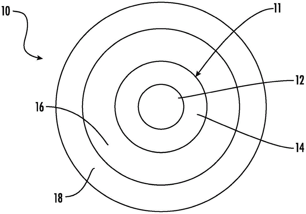
An optical fiber (10) is provided comprising a core region (12) and a cladding region (14). The core region (12) is formed from silica glass doped with chlorine and/or alkali metals. The cladding region (14) surrounds the core region (12) and includes an inner cladding directly adjacent to the core region, an outer cladding surrounding the inner cladding, and a groove arranged in radial direction between the inner cladding and the outer cladding area. The grooved region has a volume of about 30% Δ-micron 2 or greater. In addition, the optical fiber has an effective area of about 100 microns2 or less at 1550 nm.
Description
本申请要求2020年4月3日提交的荷兰专利申请第2025269号的优先权权益,其要求2020年3月18日提交的美国临时专利申请系列号62/991,231的优先权,本文以它们的内容作为基础并将其全文通过引用结合入本文。This application claims the benefit of priority to Dutch Patent Application No. 2025269, filed April 3, 2020, which claims priority to U.S. Provisional Patent Application Serial No. 62/991,231, filed March 18, 2020, the contents of which are incorporated herein as a basis and is hereby incorporated by reference in its entirety.
技术领域technical field
本公开内容属于光纤。更具体来说,本公开内容属于构造成用于海底环境的光纤光缆。最具体来说,本公开内容属于在没有明显增加微弯曲敏感性的情况下直径减小的光纤。This disclosure pertains to optical fibers. More specifically, the present disclosure pertains to fiber optic cables configured for use in subsea environments. Most particularly, the present disclosure pertains to reduced diameter optical fibers without a significant increase in microbending sensitivity.
背景技术Background technique
海底光缆设计成承载横跨陆地大洋和海洋的电信信号。在过去数年间,海底光缆上的电信信号急剧增加,目前这些光缆上承载了超过90%的洲际通讯信号。因此,由于受到不同大洲之间的互联网通讯增长的驱动,增加了对于此类海底光缆传输能力的需求。Submarine fiber optic cables are designed to carry telecommunications signals across land, oceans and seas. Over the past few years, telecommunication signals on submarine fiber optic cables have increased dramatically, and these cables now carry more than 90% of intercontinental communication signals. Therefore, driven by the growth of Internet communication between different continents, there is an increased demand for the transmission capacity of such submarine optical cables.
增加海底光缆传输能力的传统方案包括波分复用来增加传输通道数量以及先进调制格式来增加每个通道上的数据速率。然而,通道数量和通道数据速率接近实践极限,因此使得这些方案不再实用。增加海底光缆的传输能力的另一种可行方案是通过增加光缆的整体直径来增加光缆内的光纤数量。然而,由于为了提供光缆的方便布置使得海底光缆的直径受限,这种方案也不再实用。由于重量增加以及布置海面下光缆的轮船的储存能力有限,增加海底光缆的直径使得对于光缆的管理更为困难。Traditional approaches to increasing the transmission capacity of submarine cables include wavelength division multiplexing to increase the number of transmission channels and advanced modulation formats to increase the data rate on each channel. However, the number of lanes and lane data rates approach practical limits, thus making these schemes impractical. Another possible solution to increase the transmission capacity of a submarine cable is to increase the number of optical fibers in the cable by increasing the overall diameter of the cable. However, this solution is no longer practical due to the limited diameter of the submarine cable in order to provide a convenient arrangement of the cable. Increasing the diameter of submarine cables makes cable management more difficult due to increased weight and limited storage capacity of the ships that deploy the cables below the surface.
发明内容Contents of the invention
本公开内容提供的光纤具有减小的直径从而增加海底光缆中的光纤数量,因此实现了将海底光缆的直径保持在可接受的尺寸以便于部署。具体来说,本文公开的光纤具有降低的玻璃直径和/或降低的涂层厚度,同时仍然维持了长距离传输所需的微弯曲特性。更具体来说,此处公开的光纤提供了低衰减、低微弯曲敏感性以及紧凑形式下的高抗穿刺性。减小的玻璃直径和/或减小的涂层厚度可以用于增加标准海底光缆设计中的光纤密度。如本文所公开的此类直径减小的光纤的微弯曲性质是通过如下方式实现的:使得光纤的涂层性质与折射率分布中的凹陷包层的尺寸共同优化,以抑制光学信号的泄漏。尽管具有较小的横截面面积,但是更高模量的次级涂层改善了光纤的耐穿刺性和可操作性。The optical fibers provided by the present disclosure have reduced diameters to increase the number of fibers in a submarine cable, thus enabling the diameter of the submarine cable to be kept at an acceptable size for deployment. Specifically, the optical fibers disclosed herein have reduced glass diameter and/or reduced coating thickness, while still maintaining the microbending properties required for long-distance transmission. More specifically, the optical fibers disclosed herein provide low attenuation, low microbending sensitivity, and high puncture resistance in a compact format. Reduced glass diameter and/or reduced coating thickness can be used to increase fiber density in standard submarine cable designs. The microbending properties of such reduced-diameter optical fibers as disclosed herein are achieved by co-optimizing the coating properties of the optical fiber with the size of the depressed cladding in the refractive index profile to suppress leakage of optical signals. Despite having a smaller cross-sectional area, the higher modulus secondary coating improves the puncture resistance and handleability of the fiber.
本说明书延伸至具有包含掺杂了氯和/或碱金属的二氧化硅玻璃的纤芯区域的光纤。光纤还包括:围绕纤芯区域的包层区域,所述包层区域包括与纤芯区域直接相邻的内包层,围绕内包层的外包层,以及在径向方向上布置在内包层与外包层之间的凹槽区域,所述凹槽区域具有约30%Δ-微米2或更大的体积。此外,光纤具有1550nm处约100微米2或更小的有效面积。This specification extends to optical fibers having a core region comprising silica glass doped with chlorine and/or alkali metals. The optical fiber also includes a cladding region surrounding the core region, the cladding region including an inner cladding directly adjacent to the core region, an outer cladding surrounding the inner cladding, and an inner cladding and an outer cladding arranged in a radial direction between grooved regions having a volume of about 30% delta-micron 2 or greater. In addition, the optical fiber has an effective area of about 100 microns2 or less at 1550 nm.
本说明书还延伸至具有包含掺杂了氯和/或碱金属的二氧化硅玻璃的纤芯区域以及围绕纤芯区域的包层区域的光纤。包层区域包括与纤芯区域直接相邻的内包层、围绕内包层的外包层以及在径向方向上布置在内包层与外包层之间的凹槽区域,所述凹槽区域具有约30%Δ-微米2或更大的体积。光纤还包括环绕了包层区域的初级涂层和环绕了初级涂层的次级涂层。初级涂层具有约0.5MPa或更小的原位模量,而次级涂层具有约1500MPa或更大的原位模量。次级涂层的直径约为210微米或更小。The description also extends to optical fibers having a core region comprising silica glass doped with chlorine and/or alkali metals and a cladding region surrounding the core region. The cladding region includes an inner cladding directly adjacent to the core region, an outer cladding surrounding the inner cladding, and a groove region arranged between the inner cladding and the outer cladding in the radial direction, the groove region having about 30% Delta-micron volume of 2 or greater. The optical fiber also includes a primary coating surrounding the cladding region and a secondary coating surrounding the primary coating. The primary coating has an in situ modulus of about 0.5 MPa or less, while the secondary coating has an in situ modulus of about 1500 MPa or greater. The diameter of the secondary coating is about 210 microns or less.
本说明书还延伸至多纤芯光纤,其具有:包含掺杂了氯和/或碱金属的二氧化硅玻璃的第一纤芯,围绕第一纤芯的第一内包层,以及围绕第一内包层且包含体积约为30%Δ-微米2或更大的第一凹槽区域的第一外包层。此外,多纤芯光纤具有:包含掺杂了氯和/或碱金属的二氧化硅玻璃的第二纤芯,围绕第二纤芯的第二内包层,以及围绕第二内包层且包含体积约为30%Δ-微米2或更大的第二凹槽区域的第二外包层。共用包层围绕第一纤芯和第二纤芯。此外,第一纤芯和第二纤芯分别具有1550nm处约100微米2或更小的有效面积。The specification also extends to multi-core optical fibers having a first core comprising silica glass doped with chlorine and/or alkali metals, a first inner cladding surrounding the first core, and a first inner cladding surrounding the first inner cladding and comprising a first overcladding volume of about 30% delta-micron 2 or greater of the first groove region. In addition, the multi-core optical fiber has a second core comprising silica glass doped with chlorine and/or alkali metals, a second inner cladding surrounding the second core, and surrounding the second inner cladding and containing a volume of about A second overcladding of 30% delta-micron 2 or greater in the second groove area. A common cladding surrounds the first core and the second core. In addition, the first core and the second core each have an effective area of about 100 microns2 or less at 1550 nm.
在以下的详细描述中给出了其他特征和优点,其中的部分特征和优点对本领域技术人员而言是容易理解的,或通过实施文字描述和其权利要求书以及附图中所述实施方式而被认识。Other features and advantages are given in the following detailed description, some of which are easily understood by those skilled in the art, or can be realized by implementing the written description, its claims and the embodiments described in the accompanying drawings. be known.
要理解的是,上面的一般性描述和下面的详细描述都仅仅是示例性的,用来提供理解权利要求书的性质和特点的总体评述或框架。It is to be understood that both the foregoing general description and the following detailed description are exemplary only, and are intended to provide a general overview or framework for understanding the nature and character of the claims.
所附附图提供了进一步理解,附图被结合在本说明书中并构成说明书的一部分。附图是对本公开内容所选择方面的示意,并且与说明书一起用来对属于本公开内容的方法、产品和组合物的原理与操作进行解释。The accompanying drawings are included to provide a further understanding, and are incorporated in and constitute a part of this specification. The drawings are schematic representations of selected aspects of the disclosure, and together with the description serve to explain the principles and operations of the methods, products and compositions belonging to the disclosure.
附图说明Description of drawings
图1是根据本公开内容实施方式的经涂覆的光纤的示意图;Figure 1 is a schematic diagram of a coated optical fiber according to an embodiment of the disclosure;
图2是根据本公开内容实施方式的光纤带的示意图;Figure 2 is a schematic illustration of a fiber optic ribbon according to an embodiment of the disclosure;
图3是根据本公开内容实施方式的光纤光缆的示意图;3 is a schematic diagram of a fiber optic cable according to an embodiment of the disclosure;
图4是根据本公开内容实施方式的光纤的横截面示意图;4 is a schematic cross-sectional view of an optical fiber according to an embodiment of the disclosure;
图5显示根据本公开内容实施方式的光纤的相对折射率分布;Figure 5 shows the relative refractive index profile of an optical fiber according to an embodiment of the disclosure;
图6A-6E显示根据本公开内容实施方式的光纤的相对折射率分布;6A-6E show relative refractive index profiles of optical fibers according to embodiments of the disclosure;
图7显示对于两种光纤的辐射损耗与包层半径的关系图;Figure 7 shows a plot of radiation loss versus cladding radius for two types of fiber;
图8A显示根据本公开内容实施方式的多纤芯光纤的示意图;Figure 8A shows a schematic diagram of a multi-core optical fiber according to an embodiment of the disclosure;
图8B显示根据本公开内容实施方式的多纤芯光纤的示意图;Figure 8B shows a schematic diagram of a multi-core fiber according to an embodiment of the disclosure;
图8C显示根据本公开内容实施方式的多纤芯光纤的示意图;Figure 8C shows a schematic diagram of a multi-core fiber according to an embodiment of the disclosure;
图9显示根据本公开内容实施方式的多纤芯光纤的示意图;Figure 9 shows a schematic diagram of a multi-core optical fiber according to an embodiment of the disclosure;
图10显示对于三种多纤芯光纤的串扰与纤芯间距关系图;以及Figure 10 shows a plot of crosstalk versus core spacing for three types of multi-core optical fibers; and
图11显示根据本公开内容实施方式的多纤芯光纤的纤芯的相对折射率分布。Figure 11 shows the relative refractive index profile of the cores of a multi-core optical fiber according to an embodiment of the disclosure.
具体实施方式detailed description
提供的本公开内容作为实现教导,并且可以通过参考以下描述、附图、实施例和权利要求更容易地理解。为此,本领域技术人员会意识和体会到,可以对本文所述的实施方式的各个方面进行各种变化,同时仍然获得有益结果。还显而易见的是,本实施方式所需的有益结果中的一部分可以通过选择一些特征而不利用其他的特征来获得。因此,本领域技术人员会认识到,许多更改和修改都是可能的,在某些情况下甚至是希望的,并且是本公开的一部分。因此,要理解的是,除非另有说明,否则本公开内容不限于所揭示的具体组合物、制品、装置和方法。还要理解的是,本文所使用的术语的目的仅为了描述特定的方面而不是限制性的。The present disclosure is provided as an enabling teaching and can be more readily understood by reference to the following description, drawings, examples, and claims. To this end, those skilled in the art will recognize and appreciate that various changes can be made to the various aspects of the embodiments described herein while still obtaining beneficial results. It will also be apparent that some of the desired beneficial results of this embodiment can be obtained by selecting some features and not utilizing others. Accordingly, those skilled in the art will recognize that many alterations and modifications are possible, and can in some cases even be desirable, and are a part of this disclosure. Therefore, it is to be understood that, unless otherwise indicated, the present disclosure is not limited to the particular compositions, articles of manufacture, devices and methods disclosed. It is also to be understood that the terminology used herein is for the purpose of describing particular aspects only and is not limiting.
在本说明书和下面的权利要求书中提到许多术语,这些术语应定义为具有以下含义:Throughout this specification and the following claims, a number of terms are referred to which shall be defined to have the following meanings:
“光纤”指的是玻璃部分围绕有涂层的波导。玻璃部分包括纤芯和包层,并且在本文中被称作“玻璃纤维”。"Fiber optic" refers to a coated waveguide surrounded by glass portions. The glass portion includes a core and cladding, and is referred to herein as a "glass fiber."
“径向位置”、“半径”或者径向坐标“r”指的是相对于光纤的中心线(r=0)的径向位置。"Radial position", "radius" or the radial coordinate "r" refers to the radial position relative to the centerline (r=0) of the fiber.
除非另有说明,否则“折射率”指的是1550nm波长处的折射率。Unless otherwise stated, "refractive index" refers to the refractive index at a wavelength of 1550 nm.
“折射率分布”是折射率或相对折射率与半径之间的关系。对于本文所示的在相邻纤芯和/或包层区域之间具有阶梯式边界的相对折射率分布,处理条件的正常变化可排除在相邻区域的界面处获得锋利阶梯式边界。要理解的是,虽然本文可能将折射率分布的边界显示为折射率的阶梯式变化,但是实践中,边界可能是圆化的或者任意其他方式偏离完美阶梯式功能特性。还要理解的是,在纤芯区域和/或任意包层区域内,相对折射率值可能随着径向位置发生变化。当在光纤的特定区域(例如,纤芯区域和/或任意包层区域)内,相对折射率随着径向位置发生变化时,它可以用其实际或近似的函数依赖性,或其在区域内的特定位置的值进行表示,或者以适用于该区域整体的平均值进行表示。除非另有说明,否则如果区域(例如,纤芯区域和/或任意包层区域)的相对折射率以单值或者作为适用于该区域作为整体的参数(例如,Δ或Δ%)进行表述时,要理解的是,该区域中的相对折射率是恒定的或者近似恒定的,并且对应于该单值,或者该单值或参数表示依赖于该区域中的径向位置的非恒定相对折射率的平均值。例如,如果“i”是玻璃纤维的一个区域,除非另有说明,否则参数Δi指的是该区域中通过如下等式(1)所定义的相对折射率的平均值。无论是通过设计还是正常制造变化的结果,相对折射率对于径向位置的依赖性可能是倾斜的、弯曲的、或者任意其他方式非恒定的。"Refractive index profile" is the relationship between refractive index or relative refractive index and radius. For relative index profiles shown herein with stepped boundaries between adjacent core and/or cladding regions, normal variations in processing conditions may preclude obtaining sharp stepped boundaries at the interface of adjacent regions. It is to be understood that while the boundaries of the refractive index profile may be shown herein as stepwise changes in refractive index, in practice the boundaries may be rounded or otherwise deviate from the perfect stepwise functional characteristic. It is also to be understood that relative index values may vary with radial position within the core region and/or any cladding region. When the relative index of refraction varies with radial position in a specific region of the fiber (e.g., the core region and/or any cladding region), it can be used either by its actual or approximate functional dependence, or by its region Expressed as a value at a specific location within the area, or as an average value applicable to the area as a whole. Unless otherwise stated, if the relative refractive index of a region (e.g., the core region and/or any cladding region) is expressed as a single value or as a parameter (e.g., Δ or Δ%) applicable to the region as a whole , it is to be understood that the relative refractive index in the region is constant or approximately constant and corresponds to the single value, or that the single value or parameter represents a non-constant relative refractive index depending on the radial position in the region average of. For example, if "i" is a region of a glass fiber, unless otherwise specified, the parameter Δi refers to the average value of the relative refractive index in that region as defined by equation (1) below. Whether by design or as a result of normal manufacturing variations, the dependence of the relative refractive index on radial position may be sloped, curved, or in any other manner non-constant.
如本文所用,“相对折射率”如等式(1)所定义:As used herein, "relative refractive index" is defined by equation (1):
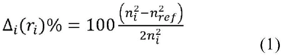
除非另外说明,否则式中ni是玻璃纤维中径向位置ri处的折射率;以及除非另外说明,否则nref是纯二氧化硅玻璃的折射率。因此,如本文所用,相对折射率百分比是相对于(在1500nm波长处的数值为1.444的)纯二氧化硅玻璃而言。除非另有说明,否则,如本文所用的相对折射率用Δ(或“Δ”)或者Δ%(或“Δ%”)表示,其数值的单位是“%”。相对折射率也可以表示为Δ(r)或Δ(r)%。where ni is the refractive index at radial position ri in the glass fiber, unless otherwise stated; and nref is the refractive index of pure silica glass, unless otherwise stated. Thus, as used herein, relative refractive index percentages are relative to pure silica glass (with a value of 1.444 at a wavelength of 1500 nm). Unless otherwise specified, the relative refractive index as used herein is represented by Δ (or "Δ") or Δ% (or "Δ%"), and the unit of the value thereof is "%". The relative refractive index can also be expressed as Δ(r) or Δ(r) %.
光纤的一个区域的平均相对折射率(Δ平均)由等式(2)决定:The average relative refractive index (Δaverage) of a region of the fiber is determined by equation (2):

式中,r内是该区域的内半径,r外是该区域的外半径,以及Δ(r)是该区域的相对折射率。where rin is the inner radius of the region, rout is the outer radius of the region, and Δ(r) is the relative refractive index of the region.
可以采用市售可得装置,例如:IFA-100光纤折射率分布仪(美国马萨诸塞州沙龙市国际光纤分析有限公司(Interfiber Analysis LLC,Sharon,MA USA))或者S14折射率分布仪(美国俄勒冈州比弗顿市光子动力有限公司(Photon Kinetics,Inc.,Beaverton,ORUSA)),来测量光纤的折射率分布。这些装置测量的是相对于测量参照折射率的折射率(n(r)-nmeas),式中,测量参照折射率nmeas是通常与油或纯二氧化硅玻璃相匹配的校准折射率。测量波长可以是:632.5nm、654nm、677.2nm、654nm、702.3nm、729.6nm、759.2nm、791.3nm、826.3nm、864.1nm、905.2nm、949.6nm、997.7nm、1050nm,或者其间的任意波长。然后如等式(1)所定义的那样将绝对折射率n(r)用于计算相对折射率。Commercially available devices can be used, such as: IFA-100 fiber optic profiler (Interfiber Analysis LLC, Sharon, MA USA) or S14 profiler (Interfiber Analysis LLC, Sharon, MA USA) Beaverton City Photon Dynamics Co., Ltd. (Photon Kinetics, Inc., Beaverton, ORUSA)) to measure the refractive index distribution of the optical fiber. These devices measure the refractive index relative to the measured reference index (n(r)-n meas ), where the measured reference index n meas is a calibrated index that is usually matched to oil or pure silica glass. The measurement wavelength can be: 632.5nm, 654nm, 677.2nm, 654nm, 702.3nm, 729.6nm, 759.2nm, 791.3nm, 826.3nm, 864.1nm, 905.2nm, 949.6nm, 997.7nm, 1050nm, or any wavelength in between. The absolute refractive index n(r) is then used to calculate the relative refractive index as defined by equation (1).
术语“α-分布”或者“α分布”指的是相对折射率分布Δ(r),其具有等式(3)所限定的函数形式:The term "alpha-distribution" or "alpha distribution" refers to the relative refractive index distribution Δ(r), which has the functional form defined by equation (3):

式中,ro是Δ(r)为最大值时的径向位置,Δ(r0)>0,rz>r0是Δ(r)减小到它最小值时的径向位置,以及r的范围是ri≤r≤rf,式中,ri是α-分布的起始径向位置,rf是α-分布的最终径向位置,以及α是实数。在本文中,α-分布的Δ(r0)可以被称作Δ最大值,或者当指的是光纤的具体区域i时,称作Δi最大值。当光纤纤芯区域的相对折射率分布用α-分布描述时,且r0位于中心线(r=0)以及rz对应纤芯区域的外半径r1并且Δ1(r1)=0,等式(3)简化为等式(4):where r o is the radial position when Δ(r) is the maximum value, Δ(r 0 )>0, r z >r 0 is the radial position when Δ(r) decreases to its minimum value, and The range of r is ri ≤ r ≤ r f , where ri is the initial radial position of the α-distribution, r f is the final radial position of the α-distribution, and α is a real number. In this context, Δ(r 0 ) of the α-distribution may be referred to as Δ max , or when referring to a specific region i of the fiber, as Δ i max . When the relative refractive index profile of the fiber core region is described by α-distribution, and r 0 is located at the centerline (r=0) and r z corresponds to the outer radius r 1 of the core region and Δ 1 (r 1 )=0, Equation (3) reduces to Equation (4):

当纤芯区域具有等式(4)所描述的折射率时,可以通过如下方式从测得的相对折射率分布确定外半径r1。最大相对折射率Δ1最大值、α和外半径r1est的估算值是通过测得的相对折射率分布的检查得到的,并且用于产生r=-r1est与r=r1est之间的试探函数。如图5和6所示是根据本公开内容实施方式具有通过α-分布所描述的纤芯的代表性玻璃纤维的相对折射率分布。When the core region has a refractive index described by equation (4), the outer radius r 1 can be determined from the measured relative refractive index profile as follows. Estimates of the maximum relative refractive index Δ1max , α, and outer radius r 1est are obtained by inspection of the measured relative refractive index profile and are used to generate a trial between r = -r 1est and r = r 1est function. Shown in Figures 5 and 6 are the relative refractive index profiles of representative glass fibers having a core described by an α-profile according to an embodiment of the disclosure.
“凹槽体积”定义如下:The "groove volume" is defined as follows:

式中,r凹槽,内是折射率分布的凹槽区域的内半径,r凹槽,外是折射率分布的凹槽区域的外半径,Δ凹槽(r)是折射率分布的凹槽区域的相对折射率,以及r是光纤中的径向位置。凹槽体积是绝对值并且是正数,在本文中表述的单位如下:%Δ微米2、%Δ-微米2、%Δ-μm2或%Δμm2,这些单位在本文中可互换使用。凹槽区域在本文中也被称作凹陷折射率包层区域,并且凹槽体积在本文中也被称作V3。where, rgroove, inner is the inner radius of the groove region of the refractive index distribution, rgroove, outer is the outer radius of the groove region of the refractive index distribution, and Δgroove (r) is the groove of the refractive index distribution The relative refractive index of the region, and r is the radial position in the fiber. Groove volume is an absolute value and a positive number, expressed herein in the following units: % Δμm2 , %Δ - μm2, %Δ - μm2 or % Δμm2 , which units are used interchangeably herein. The groove region is also referred to herein as a depressed index cladding region, and the groove volume is also referred to herein as V 3 .
光纤的“模场直径”或“MFD”由等式(6)定义:The "mode field diameter" or "MFD" of a fiber is defined by equation (6):
MFD=2w (6)MFD=2w (6)

式中,f(r)是导光学信号的电场分布的横向分量,r是光纤中的径向位置。“模场直径”或“MFD”依赖于光学信号的波长,并且在本文中记录的是1310nm、1550nm和1625nm波长的情况。当本文涉及模场直径时,会具体指出波长。除非另有说明,否则模场直径指的是具体波长处的LP01模式。where f(r) is the transverse component of the electric field distribution of the guided optical signal, and r is the radial position in the fiber. "Mode Field Diameter" or "MFD" is dependent on the wavelength of the optical signal, and is reported herein for wavelengths of 1310 nm, 1550 nm and 1625 nm. When the text refers to mode field diameter, the wavelength is specifically indicated. Unless otherwise stated, mode field diameters refer to the LP 01 mode at a specific wavelength.
光纤的“有效面积”的定义如等式(7):The "effective area" of an optical fiber is defined in Equation (7):
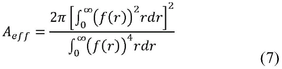
式中,f(r)是导光学信号的电场的横向分量,r是光纤中的径向位置。“有效面积”或者“Aeff”取决于光学信号的波长,并且要理解的是,在本文中指的是1550nm波长的情况。where f(r) is the transverse component of the electric field that guides the optical signal, and r is the radial position in the fiber. "Effective area" or "A eff " depends on the wavelength of the optical signal, and it is understood that reference is made herein to the case of a wavelength of 1550 nm.
如本文所用,术语“衰减”是光学功率随着信号沿着光纤传送时的损耗。通过IEC-60793-1-40标准(“Attenuation measurement methods(衰减测量方法)”)来测量衰减。As used herein, the term "attenuation" is the loss of optical power as a signal travels along an optical fiber. Attenuation is measured by the IEC-60793-1-40 standard ("Attenuation measurement methods").
本文中,可以通过如IEC-60793-1-47标准(“Measurement methods and testprocedures-Macrobending loss(测量方法和测试方案:宏弯曲损耗)”)所规定的指定测试条件下的诱发衰减来度量光纤的抗弯曲性,表述为“弯曲损耗”。例如,测试条件可以包括将光纤绕着规定直径的心轴部署或缠绕一圈或多圈,例如,绕着15mm、20mm或30mm或者类似直径的心轴缠绕1圈(例如,“1×15mm直径弯曲损耗”或者“1×20mm直径弯曲损耗”或者“1×30mm直径弯曲损耗”)并测量每圈的衰减增加。In this paper, the induced attenuation under specified test conditions as specified in the IEC-60793-1-47 standard ("Measurement methods and test procedures-Macrobending loss (Measurement methods and test procedures: Macrobending loss)") can be used to measure the optical fiber Resistance to bending, expressed as "bending loss". For example, test conditions may include deploying or winding the fiber one or more turns around a mandrel of specified diameter, for example, 1 turn around a mandrel of 15 mm, 20 mm, or 30 mm or similar diameter (e.g., "1 x 15 mm diameter Bending Loss" or "1×20mm Diameter Bending Loss" or "1×30mm Diameter Bending Loss") and measure the attenuation increase per turn.
如本文所用,“光缆截止波长”或者“光缆截止”涉及的是IEC 60793-1-44标准(“Measurement methods and test procedures–Cut-off wavelength(测量方法和测试方案:截止波长)”)所规定的22m光缆截止测试。As used herein, "cable cut-off wavelength" or "cable cut-off" refers to the IEC 60793-1-44 standard ("Measurement methods and test procedures–Cut-off wavelength (measurement methods and test programs: cut-off wavelength)") 22m optical cable cut-off test.
本文公开的光纤包括:纤芯区域,围绕了纤芯区域的包层区域,以及围绕了包层区域的涂层。纤芯区域和包层区域是玻璃。包层区域包括多个区域。所述多个包层区域优选是同心区域。包层区域包括内包层区域、凹陷折射率包层区域和外包层区域。内包层区域围绕且与纤芯区域直接相邻。凹陷折射率包层区域围绕且与内包层区域直接相邻,从而使得凹陷折射率包层区域在径向方向上布置在内包层与外包层之间。外包层区域围绕且与凹陷折射率区域直接相邻。凹陷折射率区域的相对折射率低于内包层和外包层区域。凹陷折射率包层区域在本文中也可以称作凹槽或者凹槽区域。内包层区域的相对折射率可以小于、等于、或者大于外包层区域的相对折射率。凹陷折射率包层区域可以起到降低弯曲损耗和微弯曲敏感性的作用。纤芯区域、内包层区域、凹陷折射率包层区域和外包层区域也分别被称作纤芯、包层、内包层、凹陷折射率包层和外包层。The optical fiber disclosed herein includes a core region, a cladding region surrounding the core region, and a coating surrounding the cladding region. The core and cladding regions are glass. The cladding region includes multiple regions. The plurality of cladding regions are preferably concentric regions. The cladding region includes an inner cladding region, a depressed index cladding region and an outer cladding region. The inner cladding region surrounds and is directly adjacent to the core region. The depressed index cladding region surrounds and directly adjoins the inner cladding region such that the depressed index cladding region is disposed between the inner cladding and the outer cladding in a radial direction. The outer cladding region surrounds and is directly adjacent to the depressed index region. The depressed index region has a lower relative index of refraction than the inner and outer cladding regions. A depressed index cladding region may also be referred to herein as a groove or a grooved region. The relative refractive index of the inner cladding region may be less than, equal to, or greater than the relative refractive index of the outer cladding region. The depressed-index cladding region can function to reduce bend loss and microbending sensitivity. The core region, inner cladding region, depressed index cladding region and outer cladding region are also referred to as core, cladding, inner cladding, depressed index cladding and outer cladding, respectively.
如本文任何地方所用的那样,径向位置r1和相对折射率Δ1或Δ1(r)涉及的是纤芯区域,径向位置r2和相对折射率Δ2或Δ2(r)涉及的是内包层区域,径向位置r3和相对折射率Δ3或Δ3(r)涉及的是凹陷折射率包层区域,径向位置r4和相对折射率Δ4或Δ4(r)涉及的是外包层区域,径向位置r5涉及的是初级涂层,径向位置r6涉及的是次级涂层,以及径向位置r7涉及的是任选的第三级涂层。As used anywhere herein, radial position r 1 and relative refractive index Δ 1 or Δ 1 (r) refer to the core region, radial position r 2 and relative refractive index Δ 2 or Δ 2 (r) refer to is the inner cladding region, radial position r 3 and relative refractive index Δ 3 or Δ 3 (r) is related to the depressed index cladding region, radial position r 4 and relative refractive index Δ 4 or Δ 4 (r) Referring to the outer cladding region, radial position r 5 relates to the primary coating, radial position r 6 relates to the secondary coating, and radial position r 7 relates to the optional tertiary coating.
相对折射率Δ1(r)具有最大值Δ1最大值和最小值Δ1最小值。相对折射率Δ2(r)具有最大值Δ2最大值和最小值Δ2最小值。相对折射率Δ3(r)具有最大值Δ3最大值和最小值Δ3最小值。相对折射率Δ4(r)具有最大值Δ4最大值和最小值Δ4最小值。在相对折射率在区域上是恒定或者近似恒定的实施方式中,相对折射率的最大值和最小值是相等或者近似相等的。除非另有说明,否则如果对于区域的相对折射率记录的是单值的话,则该单值对应于该区域的平均值。The relative refractive index Δ 1 (r) has a maximum value Δ 1 max and a minimum value Δ 1 min . The relative refractive index Δ 2 (r) has a maximum value Δ 2max and a minimum value Δ2min. The relative refractive index Δ 3 (r) has a maximum value Δ 3max and a minimum value Δ3min. The relative refractive index Δ 4 (r) has a maximum value Δ 4max and a minimum value Δ 4min . In embodiments where the relative index of refraction is constant or approximately constant over the area, the maximum and minimum values of the relative index of refraction are equal or approximately equal. Unless otherwise stated, where a single value is reported for the relative refractive index of a region, that single value corresponds to the average value for that region.
要理解的是,中心纤芯区域是基本圆柱形形状,以及围绕的内包层区域、凹陷折射率包层区域、外包层区域、初级涂层和次级涂层是基本环状形状。环状区域可以用内半径和外半径进行表征。在本文中,径向位置r1、r2、r3、r4、r5、r6和r7涉及的分别是纤芯、内包层、凹陷折射率包层、外包层、初级涂层、次级涂层和第三级涂层的最外半径。在没有第三级涂层的实施方式中,半径r6还对应于光纤的外半径。当存在第三级涂层时,半径r7对应于光纤的外半径。It will be appreciated that the central core region is substantially cylindrical in shape and the surrounding inner cladding region, depressed index cladding region, outer cladding region, primary coating and secondary coating are substantially annular in shape. Annular regions can be characterized by inner and outer radii. In this paper, the radial positions r 1 , r 2 , r 3 , r 4 , r 5 , r 6 and r 7 refer to the core, inner cladding, depressed index cladding, outer cladding, primary coating, The outermost radius of the secondary and tertiary coatings. In embodiments without a tertiary coating, the radius r6 also corresponds to the outer radius of the fiber. The radius r7 corresponds to the outer radius of the fiber when a tertiary coating is present.
当两个区域相互直接相邻时,两个区域中靠内那个的外半径与两个区域中靠外那个的内半径是一致的。例如,光纤包括凹陷折射率包层区域,其被外包层区域围绕且直接相邻。半径r3对应凹陷折射率包层区域的外半径和外包层区域的内半径。相对折射率分布还包括凹陷折射率包层区域,其围绕且与内包层区域直接相邻。径向位置r2对应内包层区域的外半径和凹陷折射率包层区域的内半径。类似地,径向位置r1对应于纤芯区域的外半径和内包层区域的内半径。When two regions are directly adjacent to each other, the outer radius of the inner of the two regions is identical to the inner radius of the outer of the two regions. For example, an optical fiber includes a depressed index cladding region surrounded by and immediately adjacent to an outer cladding region. Radius r3 corresponds to the outer radius of the depressed-index cladding region and the inner radius of the outer cladding region. The relative refractive index profile also includes a depressed index cladding region surrounding and directly adjacent to the inner cladding region. The radial position r2 corresponds to the outer radius of the inner cladding region and the inner radius of the depressed-index cladding region. Similarly, radial position r1 corresponds to the outer radius of the core region and the inner radius of the inner cladding region.
径向位置r2与径向位置r1之差在本文被称作内包层区域的厚度。径向位置r3与径向位置r2之差在本文被称作凹陷折射率包层区域的厚度。径向位置r4与径向位置r3之差在本文被称作外包层区域的厚度。径向位置r5与径向位置r4之差在本文被称作初级涂层的厚度。径向位置r6与径向位置r5之差在本文被称作次级涂层的厚度。The difference between radial position r2 and radial position r1 is referred to herein as the thickness of the inner cladding region. The difference between radial position r3 and radial position r2 is referred to herein as the thickness of the depressed index cladding region. The difference between radial position r4 and radial position r3 is referred to herein as the thickness of the outer cladding region. The difference between radial position r5 and radial position r4 is referred to herein as the thickness of the primary coating. The difference between radial position r6 and radial position r5 is referred to herein as the thickness of the secondary coating.
如下文进一步详述,纤芯区域、内包层区域、凹陷折射率包层区域和外包层区域的相对折射率可以是不同的。这些区域可以分别由经过掺杂或者未经掺杂的二氧化硅玻璃形成。可以采用本领域技术人员已知的技术,通过结合正掺杂剂或负掺杂剂,结合的水平设计成提供目标折射率或折射率分布,从而完成相对于未经掺杂的二氧化硅玻璃的折射率的变化。正掺杂剂是增加了玻璃相对于未掺杂的玻璃组合物的折射率的掺杂剂。负掺杂剂是降低了玻璃相对于未掺杂的玻璃组合物的折射率的掺杂剂。在一个实施方式中,未经掺杂的玻璃是二氧化硅玻璃。当未掺杂的玻璃是二氧化硅玻璃时,正掺杂剂包括Cl、Br、Ge、Al、P、Ti、Zr、Nb、和Ta,以及负掺杂剂包括F和B。可以通过不掺杂或者在区域的厚度上以均匀的浓度进行掺杂,来形成恒定折射率的区域。通过掺杂剂在区域厚度上的非均匀空间分布和/或通过在不同区域中结合不同掺杂剂,来形成折射率变化的区域。还可以通过在二氧化硅玻璃中结合空穴来完成负掺杂。空穴对应于填充了空气或其他气体(例如,N2、Ar、SO2、CO2、Kr、O2)的局部区域和/或延伸长度小于玻璃纤维全长的真空空间。优选地,空穴沿着玻璃纤维的长度是随机分布或者非周期性分布。As described in further detail below, the relative indices of refraction of the core region, inner cladding region, depressed index cladding region, and outer cladding region may be different. These regions can be formed from doped or undoped silica glass, respectively. Relative to undoped silica glass, this can be accomplished by incorporating positive or negative dopants at levels designed to provide a target refractive index or refractive index profile using techniques known to those skilled in the art. changes in the refractive index. Positive dopants are dopants that increase the refractive index of the glass relative to the undoped glass composition. Negative dopants are dopants that lower the refractive index of the glass relative to an undoped glass composition. In one embodiment, the undoped glass is silica glass. When the undoped glass is silica glass, positive dopants include Cl, Br, Ge, Al, P, Ti, Zr, Nb, and Ta, and negative dopants include F and B. Regions of constant refractive index can be formed by being undoped or by doping at a uniform concentration over the thickness of the region. Regions of varying refractive index are formed by non-uniform spatial distribution of dopants over the thickness of the region and/or by incorporation of different dopants in different regions. Negative doping can also be accomplished by incorporating holes in the silica glass. A void corresponds to a localized area filled with air or other gas (eg, N2 , Ar, SO2, CO2 , Kr, O2 ) and/or a vacuum space extending less than the full length of the glass fiber. Preferably, the voids are randomly or non-periodically distributed along the length of the glass fiber.
杨氏模量、%拉伸和撕裂强度的数值指的是通过本文所述方案的测量条件下确定的数值。The values of Young's modulus, % tensile and tear strength refer to values determined under the measurement conditions by the protocol described herein.
下面将详细参见本说明书的示意性实施方式。The following will refer to the exemplary embodiments of this specification in detail.
一个实施方式涉及光纤。光纤包括被涂层围绕的玻璃纤维。图1以横截面示意图显示光纤的例子。光纤10包括被初级涂层16和次级涂层18环绕的玻璃纤维11。在一些实施方式中,次级涂层18可以包含颜料。下面提供了对于玻璃纤维11、初级涂层16和次级涂层18的进一步描述。此外,一层或多层第三级墨层可以围绕次级涂层18。One embodiment involves optical fibers. Optical fibers consist of glass fibers surrounded by a coating. Figure 1 shows an example of an optical fiber schematically in cross section.
图2显示光纤带30,其可以包括多根光纤20和包封所述多根光纤的基质32。光纤20分别包括:纤芯区域、包层区域、初级涂层和次级涂层,如上文所述。如上文所述,光纤20还可以包括第三级涂层。Figure 2 shows a
如图2所示,光纤20以基本平面和平行关系相互对准。通过任意数种已知构造(例如,边缘粘结的带、薄包封的带、厚包封的带或者多层带),通过制造光纤带的常规方法,用带基质32将光纤包封在光纤带30中。图2的实施方式中的光纤带30含有十二(12)根光纤20。然而,考虑可以将任意数量的光纤20(例如,2根或更多根)用于形成特定用途的光纤带30。带基质32的拉伸性质类似于次级涂层的拉伸性质,并且可以通过与用于制备次级涂层相同、相似或者不同的组合物形成。As shown in FIG. 2, the
图3显示光纤光缆40,其包括被夹套42所围绕的多根光纤20。在一些实施方式中,光纤光缆40是海底光缆。光纤20可以以致密或疏松的方式封装成被夹套42的内表面44包封的导管。夹套42中所放入的光纤的数量被称作光纤光缆40的“光纤数”。如下文进一步讨论的那样,本公开内容的光纤具有减小的直径,从而提供了高“光纤数”。FIG. 3 shows a
夹套42通过挤出的聚合物材料形成,并且可以包括聚合物或者其他材料的多层同心层。光纤光缆40可以包括嵌入在夹套42中或者放在被内表面44所限定的导管中的一个或多个强化元件(未示出)。强化元件包括比夹套42更为刚性的纤维或棒。强化元件可以由金属、编织钢、玻璃强化塑料、纤维玻璃或者其他合适材料制造。光纤光缆40可以包括被夹套42所围绕的其他层(例如,保护层、防潮层、撕裂线等。此外,光纤光缆40可以具有绞合松套管芯或其他光纤光缆构造。
玻璃纤维。glass fiber.
如图1所示,玻璃纤维11包括纤芯区域12和包层区域14,这是本领域已知的。纤芯区域12的折射率高于包层区域14,以及玻璃纤维11起到波导的作用。在许多应用中,纤芯区域12与包层区域14具有可辨识的纤芯-包层边界。或者,纤芯区域12与包层区域14会缺乏能区分的边界。As shown in FIG. 1,
在一些实施方式中,纤芯区域12具有随着相对于玻璃纤维的中心的距离发生变化的折射率。例如,纤芯区域12可以具有α-分布(如上文等式(3)所定义)的相对折射率分布,α值是大于或等于2且小于或等于100,或者例如:2至10,2至6,2至4,4至20,6至20,8至20,10至20,或者10至40。In some embodiments, the
如图4所示是示例性光纤的示意性横截面图。如上文所讨论的那样,图4的光纤可以用于海底光缆中。在图4中,光纤46包括:纤芯区域48、包层区域50、初级涂层56和次级涂层58。包层区域50包括:内包层区域51、凹陷折射率包层区域53和外包层区域55。第三级层(例如,墨层)任选地围绕或者与次级涂层直接相邻。A schematic cross-sectional view of an exemplary optical fiber is shown in FIG. 4 . As discussed above, the optical fiber of Figure 4 can be used in submarine cables. In FIG. 4 ,
如上文所讨论的那样,光纤46可以具有减小的玻璃直径和/或减小的涂层直径。此类减小的直径可以增加例如当用于标准海底光缆设计时的光纤46的光纤密度(例如,“光纤数”)。为了为具有较小直径分布的光纤46提供合适的衰减和微弯曲特性,对光纤的性质进行具体调节,如下文更进一步讨论。As discussed above,
如图5所示是根据本公开内容实施方式的玻璃纤维的代表性相对折射率分布。图5的光纤60的分布显示:纤芯区域(1),其具有外半径r1和相对折射率Δ1,所述折射率Δ1具有最大相对折射率Δ1最大值;内包层区域(2),其从径向位置r1延伸到径向位置r2并且具有相对折射率Δ2;凹陷折射率包层区域(3),其从径向位置r2延伸到径向位置r3并且具有相对折射率Δ3;以及外包层区域(4),其从径向位置r3延伸到径向位置r4并且具有相对折射率Δ4。在图5的分布中,凹陷折射率包层区域(3)可以在本文中被称作凹槽并且具有恒定或者平均的相对折射率,该折射率小于内包层区域(2)和外包层区域(4)的相对折射率。纤芯区域(1)在分布中具有最高的平均和最大相对折射率。纤芯区域(1)可以在中心线或者靠近中心线处具有较低折射率区域(现有技术中已知为“中心线下沉”)(未示出)。纤芯区域(1)可以在中心线或者靠近中心线处具有较高折射率区域(称作“中心线尖峰”)(未示出)。Shown in FIG. 5 is a representative relative refractive index profile of glass fibers according to an embodiment of the disclosure. The profile of
在图5的相对折射率分布中,玻璃纤维的纤芯区域(1)具有α-分布,α值大于或等于2且小于或等于20。α-分布的径向位置r0(对应于α1最大值)对应于光纤的中心线(r=0),而α-分布的径向位置rz对应于纤芯半径r1。在具有中心线下沉的实施方式中,径向位置r0略微偏离光纤的中心线。在一些实施方式中,在远离中心线的径向方向上,相对折射率Δ1持续减小。在其他实施方式中,相对折射率Δ1在中心线与r1之间的一些径向位置上变化,并且在中心线与r1之间的其他径向位置上还包括恒定或者近似恒定数值。In the relative refractive index profile of FIG. 5 , the core region ( 1 ) of the glass fiber has an α-profile with an α value greater than or equal to 2 and less than or equal to 20. The radial position r 0 of the α-distribution (corresponding to the maximum value of α 1 ) corresponds to the centerline of the fiber (r=0), while the radial position r z of the α-distribution corresponds to the core radius r 1 . In embodiments with a centerline dip, the radial position r0 is slightly offset from the centerline of the fiber. In some embodiments, the relative refractive index Δ1 continues to decrease in a radial direction away from the centerline. In other embodiments, the relative refractive index Δ1 varies at some radial positions between the centerline and r1 , and includes constant or approximately constant values at other radial positions between the centerline and r1 .
在图5中,从内包层区域(2)到凹陷折射率包层区域(3)的过渡区域61以及从凹陷折射率包层区域(3)到外包层区域(4)的过渡区域62显示为阶梯状变化。要理解的是,阶梯状变化是理想化的,在实践中,过渡区域61和/或过渡区域62可能不是如图5所示的严格垂直的情况。作为替代,过渡区域61和/或过渡区域62可能具有斜率或者曲率。当过渡区域61和/或过渡区域62不是垂直的情况时,凹陷折射率包层区域(3)的内半径r2和外半径r3分别对应过渡区域61和62的中点。中点对应凹陷折射率包层区域(3)的深度63的一半处。In FIG. 5, the
在如图5所示的相对折射率分布中的相对折射率Δ1、Δ2、Δ3和Δ4的相对次序满足如下条件:Δ1最大值>Δ4>Δ3且Δ1最大值>Δ2>Δ3。Δ2和Δ4的值可以相等或者一个比另一个大,但是Δ2和Δ4都在Δ1最大值与Δ3之间。The relative order of the relative refractive indices Δ 1 , Δ 2 , Δ 3 and Δ 4 in the relative refractive index profile shown in Figure 5 satisfies the following conditions: Δ 1 max > Δ 4 > Δ 3 and Δ 1 max > Δ 2 >Δ 3 . The values of Δ2 and Δ4 may be equal or one larger than the other, but both Δ2 and Δ4 are between the maximum value of Δ1 and Δ3 .
相对折射率Δ1、Δ2、Δ3和Δ4基于纤芯区域、内包层区域、凹陷折射率包层区域和外包层区域中所用的材料。下文提供了对于相对折射率Δ1、Δ2、Δ3和Δ4的这些材料的描述。The relative indices of refraction Δ 1 , Δ 2 , Δ 3 and Δ 4 are based on the materials used in the core region, inner cladding region, depressed index cladding region and outer cladding region. A description of these materials for relative refractive indices Δ 1 , Δ 2 , Δ 3 and Δ 4 is provided below.
纤芯区域Core area
纤芯区域包括二氧化硅玻璃。纤芯区域的二氧化硅玻璃可以是未掺杂的二氧化硅玻璃、正掺杂的二氧化硅玻璃和/或负掺杂的二氧化硅玻璃。正掺杂的二氧化硅玻璃包括掺杂了碱金属氧化物(例如,Na2O、K2O、Li2O、Cs2O或Rb2O)和/或卤素的二氧化硅玻璃。负掺杂的二氧化硅玻璃包括掺杂了氟的二氧化硅玻璃。在一些实施方式中,纤芯区域的二氧化硅玻璃不含Ge和/或不含Cl;也就是说,纤芯区域包括不含有锗和/或氯的二氧化硅玻璃。The core region includes silica glass. The silica glass in the core region may be undoped silica glass, positively doped silica glass and/or negatively doped silica glass. Positively doped silica glasses include silica glasses doped with alkali metal oxides (eg, Na2O, K2O, Li2O , Cs2O , or Rb2O ) and/or halogens. Negatively doped silica glasses include fluorine-doped silica glasses. In some embodiments, the silica glass of the core region is Ge-free and/or Cl-free; that is, the core region comprises silica glass free of germanium and/or chlorine.
纤芯区域可以包括掺杂了至少一种碱金属(例如:锂(Li)、钠(Na)、钾(K)、铷(Rb)、铯(Cs)和/或钫(Fr))的二氧化硅玻璃。在一些实施方式中,二氧化硅玻璃掺杂了钠、钾和铷的组合。二氧化硅玻璃的峰值碱性物质浓度可以是如下范围:约10ppm至约500,或者约20ppm至约450ppm,或者约50ppm至约300ppm,或者约10ppm至约200ppm,或者约10ppm至约150ppm。以所公开的范围掺杂碱金属导致瑞利散射的下降,从而提供了较低的光纤衰减。The core region may comprise bismuth doped with at least one alkali metal such as lithium (Li), sodium (Na), potassium (K), rubidium (Rb), cesium (Cs), and/or francium (Fr). silica glass. In some embodiments, the silica glass is doped with a combination of sodium, potassium, and rubidium. The silica glass may have a peak alkalinity concentration in the range of about 10 ppm to about 500, alternatively about 20 ppm to about 450 ppm, alternatively about 50 ppm to about 300 ppm, alternatively about 10 ppm to about 200 ppm, alternatively about 10 ppm to about 150 ppm. Doping with alkali metals in the disclosed ranges results in a reduction in Rayleigh scattering, thereby providing lower fiber attenuation.
在一些实施方式中,纤芯区域包括掺杂了碱金属且掺杂了作为负掺杂剂的氟的二氧化硅玻璃。图5和6显示负掺杂的二氧化硅玻璃的示例性实施方式。玻璃纤维中的氟浓度是如下范围:约0.1重量%至约2.5重量%,或者约0.25重量%至约2.25重量%,或者约0.3重量%至约2.0重量%。In some embodiments, the core region comprises silica glass doped with an alkali metal and fluorine as a negative dopant. Figures 5 and 6 show exemplary embodiments of negatively doped silica glass. The fluorine concentration in the glass fibers ranges from about 0.1% to about 2.5% by weight, or from about 0.25% to about 2.25% by weight, or from about 0.3% to about 2.0% by weight.
在其他实施方式中,纤芯区域包括掺杂了卤素(例如,氯)的二氧化硅玻璃。图6B-6D显示掺杂了氯的二氧化硅玻璃的示例性实施方式。玻璃纤维中的氯浓度是如下范围:约0.4重量%至约2.2重量%,或者约0.6重量%至约2.0重量%,或者约1.0重量%至约1.9重量%,或者约1.6重量%,或者约1.8重量%。In other embodiments, the core region comprises silica glass doped with a halogen (eg, chlorine). 6B-6D show exemplary embodiments of chlorine doped silica glass. The chlorine concentration in the glass fibers is in the following ranges: about 0.4% by weight to about 2.2% by weight, or about 0.6% by weight to about 2.0% by weight, or about 1.0% by weight to about 1.9% by weight, or about 1.6% by weight, or about 1.8% by weight.
纤芯区域的半径r1是如下范围:约3.0微米至约6.0微米,或者约3.5微米至约5.5微米,或者约4.0微米至约5.0微米,或者约4.2微米至约4.7微米。在一些实施方式中,纤芯区域包括具有恒定或者近似恒定相对折射率的部分,其在径向方向上的宽度是:至少1.0微米,或者至少2.0微米,或者至少3.0微米,或者至少4.0微米,或者1.0微米至4.0微米,或者2.0微米至3.0微米。在一些实施方式中,纤芯区域具有恒定或者近似恒定相对折射率的部分具有相对折射率Δ1最小值。The radius r 1 of the core region is in the range of about 3.0 microns to about 6.0 microns, or about 3.5 microns to about 5.5 microns, or about 4.0 microns to about 5.0 microns, or about 4.2 microns to about 4.7 microns. In some embodiments, the core region includes a portion with a constant or approximately constant relative refractive index, the width of which in the radial direction is: at least 1.0 microns, or at least 2.0 microns, or at least 3.0 microns, or at least 4.0 microns, Or 1.0 microns to 4.0 microns, or 2.0 microns to 3.0 microns. In some embodiments, the portion of the core region having a constant or approximately constant relative refractive index has a relative refractive index Δ1 minimum .
纤芯区域的相对折射率Δ1或Δ1最大值是如下范围:约-0.15%至约0.30%,或者约-0.10%至约0.20%,或者约-0.05%至约0.15%,或者约0%至约0.10%。纤芯的最小相对折射率Δ1最小值是如下范围:约-0.20%至约-0.50%,或者约-0.30%至约-0.40%,或者约-0.32%至约-0.37%。Δ1最大值与Δ1最小值之差是:大于0.05%,或者大于0.10%,或者大于0.15%,或者大于0.20%,或者0.05%至0.40%,或者0.10%至0.35%。The relative refractive index Δ1 or Δ1 maximum of the core region is in the range of about -0.15% to about 0.30%, or about -0.10% to about 0.20%, or about -0.05% to about 0.15%, or about 0 % to about 0.10%. The minimum relative refractive index Δ1min of the core is in the range of about -0.20% to about -0.50%, or about -0.30% to about -0.40%, or about -0.32% to about -0.37%. The difference between the maximum value of Δ1 and the minimum value of Δ1 is: more than 0.05%, or more than 0.10%, or more than 0.15%, or more than 0.20%, or 0.05% to 0.40%, or 0.10% to 0.35%.
内包层区域inner cladding area
内包层区域包括掺杂了氟的负掺杂的二氧化硅玻璃和/或具有空穴的二氧化硅玻璃。内包层区域中的负掺杂剂的平均浓度大于纤芯区域中的负掺杂剂的平均浓度。在一些实施方式中,内包层区域中的氟浓度范围是:约0.50重量%至约2.00重量%,或者约0.60重量%至约1.00重量%,或者约0.70重量%至约0.80重量%。The inner cladding region comprises negatively doped silica glass doped with fluorine and/or silica glass with voids. The average concentration of negative dopants in the inner cladding region is greater than the average concentration of negative dopants in the core region. In some embodiments, the fluorine concentration in the inner cladding region ranges from about 0.50 wt% to about 2.00 wt%, or from about 0.60 wt% to about 1.00 wt%, or from about 0.70 wt% to about 0.80 wt%.
内包层区域的相对折射率Δ2或者Δ2最大值是如下范围:约-0.20%至约-0.50%,或者约-0.25%至约-0.45%,或者约-0.30%至约-0.40%,或者约-0.33%至约-0.37%。相对折射率Δ2优选是恒定的或者近似恒定的。Δ1最大值-Δ2之差(或者Δ1最大值-Δ2最大值之差)是:大于约0.25%,或者大于约0.30%,或者大于约0.35%,或者约0.25%至约0.45%的范围,或者约0.30%至约0.40%的范围。The relative refractive index Δ2 or Δ2maximum of the inner cladding region is in the range of about -0.20% to about -0.50%, or about -0.25% to about -0.45%, or about -0.30% to about -0.40%, Or about -0.33% to about -0.37%. The relative refractive index Δ2 is preferably constant or approximately constant. The difference between Δ1max - Δ2 (or the difference between Δ1max - Δ2max ) is: greater than about 0.25%, alternatively greater than about 0.30%, alternatively greater than about 0.35%, alternatively about 0.25% to about 0.45% range, or a range of about 0.30% to about 0.40%.
内包层区域的半径r2是如下范围:约7.0微米至约15.0微米,或者约7.5微米至约13.0微米,或者约8.0微米至约12.0微米,或者约8.5微米至约11.5微米,或者约9.0微米至约11.0微米,或者约9.5微米至约10.5微米。内包层区域的厚度r2-r1是如下范围:约3.0微米至约10.0微米,或者约4.0微米至约9.0微米,或者约4.5微米至约7.0微米。 The radius r of the inner cladding region is in the range of about 7.0 microns to about 15.0 microns, or about 7.5 microns to about 13.0 microns, or about 8.0 microns to about 12.0 microns, or about 8.5 microns to about 11.5 microns, or about 9.0 microns to about 11.0 microns, or from about 9.5 microns to about 10.5 microns. The thickness r2 - r1 of the inner cladding region ranges from about 3.0 microns to about 10.0 microns, or from about 4.0 microns to about 9.0 microns, or from about 4.5 microns to about 7.0 microns.
凹陷折射率包层区域Depressed-index cladding region
凹陷折射率包层区域包括负掺杂的二氧化硅玻璃。如上文所讨论的那样,优选的负掺杂剂是氟。凹陷折射率包层区域中的氟浓度范围是:约0.30重量%至约2.50重量%,或者约0.60重量%至约2.25重量%,或者约0.90重量%至约2.00重量%。The depressed index cladding region comprises negatively doped silica glass. As discussed above, the preferred negative dopant is fluorine. The fluorine concentration in the depressed index cladding region ranges from about 0.30 wt% to about 2.50 wt%, alternatively from about 0.60 wt% to about 2.25 wt%, alternatively from about 0.90 wt% to about 2.00 wt%.
相对折射率Δ3或Δ3最小值是如下范围:约-0.30%至约-0.80%,或者约-0.40%至约-0.70%,或者约-0.50%至约-0.65%。相对折射率Δ3优选是恒定的或者近似恒定的。Δ1最大值-Δ3之差(或者Δ1最大值-Δ3最小值之差,或者Δ1-Δ3之差,或者Δ1-Δ3最小值之差)是:大于约0.50%,或者大于约0.55%,或者大于约0.6%,或者约0.50%至约0.80%的范围,或者约0.55%至约0.75%的范围。Δ2-Δ3之差(或者Δ2-Δ3最小值之差,或者Δ2最大值-Δ3之差,或者Δ2最大值-Δ3最小值之差)是:大于约0.10%,或者大于约0.20%,或者大于约0.30%,或者约0.10%至约0.60%的范围,或者约0.20%至约0.60%的范围。The relative refractive index Δ3 or Δ3 minimum is in the range of about -0.30% to about -0.80%, or about -0.40% to about -0.70%, or about -0.50% to about -0.65%. The relative refractive index Δ3 is preferably constant or approximately constant. The difference of Δ1 maximum - Δ3 (or the difference of Δ1 maximum - Δ3 minimum , or the difference of Δ1 - Δ3 , or the difference of Δ1 - Δ3 minimum ) is: greater than about 0.50%, Or greater than about 0.55%, alternatively greater than about 0.6%, alternatively in the range of about 0.50% to about 0.80%, alternatively in the range of about 0.55% to about 0.75%. The difference between Δ2 - Δ3 (or the difference between Δ2 - Δ3 minimum , or the difference between Δ2 maximum - Δ3 , or the difference between Δ2 maximum - Δ3 minimum ) is: greater than about 0.10%, Or greater than about 0.20%, or greater than about 0.30%, or in the range of about 0.10% to about 0.60%, or in the range of about 0.20% to about 0.60%.
凹陷折射率包层区域的内半径是r2,并且具有上文规定的值。凹陷折射率包层区域的外半径r3是如下范围:约10.0微米至20.0微米,或者约12.0微米至约19.5微米,或者约13.0微米至约19.0微米,或者约13.5微米至约18.5微米,或者约14.0微米至约18.0微米,或者约14.5微米至约17.5微米。凹陷折射率包层区域的厚度r3-r2是如下范围:0.5微米至12.0微米,或者约1.0微米至约10.0微米,或者约1.5微米至约9.0微米,或者约2.0微米至约8.0微米。The inner radius of the depressed index cladding region is r 2 and has the value specified above. The outer radius r of the depressed index cladding region is in the range of about 10.0 microns to 20.0 microns, or about 12.0 microns to about 19.5 microns, or about 13.0 microns to about 19.0 microns, or about 13.5 microns to about 18.5 microns, or From about 14.0 microns to about 18.0 microns, or from about 14.5 microns to about 17.5 microns. The thickness r3 - r2 of the depressed index cladding region ranges from 0.5 microns to 12.0 microns, or from about 1.0 microns to about 10.0 microns, or from about 1.5 microns to about 9.0 microns, or from about 2.0 microns to about 8.0 microns.
凹陷折射率包层区域可以是偏移凹槽设计,具有约30%Δ-微米2或更大,或者约50%Δ-微米2或更大,或者约70%Δ-微米2或更小,或者约30%Δ-微米2或更大且约70%Δ-微米2或更小,或者约50%Δ-微米2或更大且约70%Δ-微米2或更小的凹槽体积。低于所公开范围的凹槽体积具有降低的弯曲性能,而高于所公开范围的凹槽体积不再以单模光纤运行。The depressed index cladding region may be an offset groove design with about 30% delta - micron or greater, or about 50% delta - micron or greater, or about 70% delta - micron or less, Either about 30% delta- micron2 or greater and about 70% delta- micron2 or less, or about 50% delta- micron2 or greater and about 70% delta- micron2 or less groove volume. Groove volumes below the disclosed range have reduced bend performance, while groove volumes above the disclosed range no longer function as single mode fibers.
本文公开的偏移凹槽设计提供了相比于与纤芯区域相邻的传统凹槽设计的优点。更具体来说,本文公开的偏移凹槽设计降低了基模的限制并为目标光纤模场直径和光缆截止特性提供了大弯曲直径(例如,弯曲直径>25mm)时改进的带损耗。此外,本文公开的凹槽设计具有凹陷折射率凹槽区域,其有利地限制了传播通过光纤的基本LP01模式的强度分布,从而降低了光纤模场直径。The offset groove design disclosed herein provides advantages over conventional groove designs adjacent to the core region. More specifically, the offset groove design disclosed herein reduces fundamental mode confinement and provides improved band loss at large bend diameters (eg, bend diameter >25 mm) for targeted fiber mode field diameters and cable cutoff characteristics. In addition, the groove designs disclosed herein have a depressed index groove region that advantageously confines the intensity distribution of the fundamental LP01 mode propagating through the fiber, thereby reducing the fiber mode field diameter.
外包层区域outer cladding area
外包层区域包括掺杂了氟的负掺杂的二氧化硅玻璃和/或具有空穴的二氧化硅玻璃。外包层区域中的负掺杂剂的平均浓度大于纤芯区域中的负掺杂剂的平均浓度。在一些实施方式中,外包层区域中的氟浓度范围是:约0.50重量%至约2.00重量%,或者约0.60重量%至约1.00重量%,或者约0.70重量%至约0.80重量%。The outer cladding region comprises negatively doped silica glass doped with fluorine and/or silica glass with voids. The average concentration of negative dopants in the outer cladding region is greater than the average concentration of negative dopants in the core region. In some embodiments, the fluorine concentration in the outer cladding region ranges from about 0.50 wt% to about 2.00 wt%, or from about 0.60 wt% to about 1.00 wt%, or from about 0.70 wt% to about 0.80 wt%.
外包层区域的相对折射率Δ4或者Δ4最大值是如下范围:约-0.20%至约-0.50%,或者约-0.25%至约-0.45%,或者约-0.30%至约-0.40%,或者约-0.33%至约0.37%。相对折射率Δ4优选是恒定的或者近似恒定的。如图5所示,相对折射率Δ4可以等于相对折射率Δ2。 The relative refractive index Δ4 or Δ4maximum of the outer cladding region is in the range of about -0.20% to about -0.50%, or about -0.25% to about -0.45%, or about -0.30% to about -0.40%, Or about -0.33% to about 0.37%. The relative refractive index Δ4 is preferably constant or approximately constant. As shown in FIG. 5 , the relative refractive index Δ 4 may be equal to the relative refractive index Δ 2 .
外包层区域的内半径是r3,并且具有上文规定的值。优选低的外半径r4以使得玻璃纤维的直径最小化从而有助于光缆中的高光纤数。外包层区域的外半径r4是:小于或等于65微米,或者小于或等于62.5微米,或者小于或等于60.0微米,或者小于或等于57.5微米,或者小于或等于55.0微米,或者小于或等于52.5微米,或者小于或等于50.0微米,或者37.5微米至62.5微米,或者40.0微米至60.0微米,或者42.5微米至57.5微米,或者45.0微米至55.0微米。因此,例如,包层区域的直径(即,外半径r4乘以2)是:约130微米或更小,或者约125微米或更小,或者约120微米或更小,或者约115微米或更小,或者约110微米或更小,或者约105微米或更小,或者约100微米或更小,或者约90微米或更小,或者约80微米或更小,或者约75微米或更小。外包层区域的厚度r4-r3是如下范围:约10.0微米至约50.0微米,或者约15.0微米至约45.0微米,或者约20.0微米至约40.0微米,或者约25.0微米至约35.0微米。The inner radius of the outer cladding region is r 3 and has the value specified above. A low outer radius r4 is preferred to minimize the diameter of the glass fibers to facilitate high fiber counts in the cable. The outer radius r4 of the outer cladding region is: 65 microns or less, or 62.5 microns or less, or 60.0 microns or less, or 57.5 microns or less, or 55.0 microns or less, or 52.5 microns or less , or less than or equal to 50.0 microns, or 37.5 microns to 62.5 microns, or 40.0 microns to 60.0 microns, or 42.5 microns to 57.5 microns, or 45.0 microns to 55.0 microns. Thus, for example, the diameter of the cladding region (i.e., outer radius r times 2 ) is: about 130 microns or less, or about 125 microns or less, or about 120 microns or less, or about 115 microns or Smaller, or about 110 microns or less, or about 105 microns or less, or about 100 microns or less, or about 90 microns or less, or about 80 microns or less, or about 75 microns or less . The thickness r 4 -r 3 of the outer cladding region is in the range of about 10.0 microns to about 50.0 microns, or about 15.0 microns to about 45.0 microns, or about 20.0 microns to about 40.0 microns, or about 25.0 microns to about 35.0 microns.
光纤特性Fiber Characteristics
根据本公开内容实施方式的光纤可以具有如下范围的模场直径:1310nm处约9微米至约9.5微米以及1550nm处约10微米至约10.5微米,光缆截止小于约1530nm。在一些实施方式中,光缆截止是:小于约1550nm,或者小于约1450nm,或者小于约1400nm,或者小于约1300nm,或者小于约1260nm。Optical fibers according to embodiments of the present disclosure may have mode field diameters in the range of about 9 microns to about 9.5 microns at 1310 nm and about 10 microns to about 10.5 microns at 1550 nm, with a cable cutoff of less than about 1530 nm. In some embodiments, the cable cutoff is: less than about 1550 nm, or less than about 1450 nm, or less than about 1400 nm, or less than about 1300 nm, or less than about 1260 nm.
此外,根据本公开内容实施方式的光纤在1550nm处可以具有如下有效面积:约100微米2或更小,或者约90微米2或更小,或者约80微米2或更小,或者约70微米2或更小,或者约70微米2至约90微米2,或者约75微米2至约85微米2,或者约80微米2。Additionally, optical fibers according to embodiments of the present disclosure may have an effective area at 1550 nm of about 100 microns or less, or about 90 microns or less, or about 80 microns or less, or about 70 microns or less, or about 70 micron 2 to about 90 micron 2 , or about 75 micron 2 to about 85 micron 2 , or about 80 micron 2 .
在1550nm波长处,本文公开的光纤的衰减是:小于或等于0.175dB/km,或者小于或等于0.170dB/km,或者小于或等于0.165dB/km,或者小于或等于0.160dB/km,或者小于或等于0.155dB/km,或者小于或等于0.150dB/km。At a wavelength of 1550nm, the attenuation of the optical fiber disclosed herein is: less than or equal to 0.175dB/km, or less than or equal to 0.170dB/km, or less than or equal to 0.165dB/km, or less than or equal to 0.160dB/km, or less than Or equal to 0.155dB/km, or less than or equal to 0.150dB/km.
如图5所示,光纤60提供了具有碱性物质掺杂的纤芯的光纤的示例性实施方式,纤芯区域(1)的相对折射率Δ1是约-0.3%至约-0.42%,以及纤芯半径(r1)是约4微米至约6.5微米。此外,光纤60的内包层区域厚度是约2微米至约12微米。光纤60具有凹槽体积为54.5%Δ-微米2的偏移凹槽设计。光纤60的包层是氟掺杂的,以及凹陷折射率包层区域具有约17.5微米的半径(r3)。下表1显示了光纤60的光学性质。As shown in FIG. 5,
表1:光纤60的光学性质Table 1: Optical Properties of
图6A显示光纤64、65的第二和第三示例性实施方式,具有碱性物质掺杂的纤芯以及大于约50%Δ-微米2的凹槽体积,以及其中,包层是氟掺杂的且凹陷折射率包层区域具有约17.5微米的半径(r3)。如下表2所示,光纤64导致1310nm处9.07微米的模场直径,而光纤65导致1310nm处9.39微米的模场直径。下表2显示了光纤64和65的光学性质。6A shows second and third exemplary embodiments of
表2:光纤64和65的光学性质Table 2: Optical properties of
图6B显示光纤66的第四示例性实施方式,具有氯浓度约为1.8重量%的氯掺杂的纤芯。光纤66还包含掺杂了氟的二氧化硅的内包层、凹陷折射率包层区域以及外包层。内包层的氟浓度为0.73重量%,凹陷折射率包层区域的氟浓度为1.5重量%,以及外包层区域的氟浓度为0.73重量%。此外,光纤66具有125微米的玻璃外直径,167微米的初级涂层外直径,以及200微米的次级涂层外直径。下表3显示了光纤66的光学性质。Figure 6B shows a fourth exemplary embodiment of an
表3:光纤66的光学性质Table 3: Optical properties of
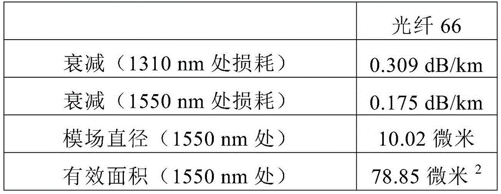

图6C显示光纤67的第五示例性实施方式,具有氯浓度约为1.8重量%的氯掺杂的纤芯。光纤67还包含掺杂了氟的二氧化硅的内包层、凹陷折射率包层区域以及外包层。内包层的氟浓度为0.73重量%,凹陷折射率包层区域的氟浓度为1.5重量%,以及外包层区域的氟浓度为0.73重量%。此外,光纤67具有125微米的玻璃外直径,167微米的初级涂层外直径,以及200微米的次级涂层外直径。光纤67在使得拉制过程期间光纤在高温炉中缓慢冷却的条件下进行拉制。更具体来说,在拉制过程期间,光纤67在运行在900℃的炉中缓慢冷却持续0.3秒的时间段。下表4显示了光纤67的光学性质。FIG. 6C shows a fifth exemplary embodiment of an
表4:光纤67的光学性质Table 4: Optical Properties of
图6D显示光纤68的第六示例性实施方式,具有氯浓度约为1.8重量%的氯掺杂的纤芯。光纤68还包含掺杂了氟的二氧化硅的内包层、凹陷折射率包层区域以及外包层。内包层的氟浓度为0.73重量%,凹陷折射率包层区域的氟浓度为1.5重量%,以及外包层区域的氟浓度为0.73重量%。此外,光纤68具有100微米的玻璃外直径,125微米的初级涂层外直径,以及160微米的次级涂层外直径。下表5显示了光纤68的光学性质。Figure 6D shows a sixth exemplary embodiment of an
表5:光纤68的光学性质Table 5: Optical Properties of


图6E显示光纤69的第七示例性实施方式,具有氯浓度约为1.8重量%的氯掺杂的纤芯。光纤69还包含掺杂了氟的二氧化硅的内包层、凹陷折射率包层区域以及外包层。内包层的氟浓度为0.73重量%,凹陷折射率包层区域的氟浓度为1.4重量%,以及外包层区域的氟浓度为0.73重量%。此外,光纤69具有100微米的玻璃外直径,131微米的初级涂层外直径,以及172微米的次级涂层外直径。下表6显示了光纤69的光学性质。Figure 6E shows a seventh exemplary embodiment of an
表6:光纤69的光学性质Table 6: Optical Properties of
光纤60以及64-69的偏移凹槽设计为本文公开的较小直径的光纤提供了改进的微弯曲敏感性。更具体来说,本文公开的偏移凹槽设计在没有牺牲光缆截止和模场直径的情况下对微弯曲进行了优化。The offset groove design of
初级和次级涂层Primary and Secondary Coatings
光穿过光纤的传递系数高度取决于施涂到玻璃纤维的涂层的性质。如上文(且参照图4)所讨论的那样,涂层通常包括初级涂层56和次级涂层58,其中,次级涂层围绕初级涂层,以及初级涂层接触玻璃纤维(其包括被包层区域围绕的中心纤芯区域)。任选的第三级层(例如,墨层)围绕并直接接触次级涂层。The transmission coefficient of light through an optical fiber is highly dependent on the nature of the coating applied to the glass fiber. As discussed above (and with reference to FIG. 4 ), the coating generally includes a
次级涂层58可以是比初级涂层56更硬的材料(更高的杨氏模量),并且设计成用来保护玻璃纤维免受光纤的加工、搬运和部署过程中的磨损或外部作用力所导致的损坏。初级涂层56可以是比次级涂层58软的材料(更低的杨氏模量),并且设计成用于缓冲或消散由于施加到次级涂层的外表面的作用力所导致的应力。初级涂层中的应力消散使得应力衰减,并且使得抵达玻璃纤维的应力最小化。初级涂层对于当布置成光缆时光纤所遭遇的微弯曲所引起的应力消散是特别重要的。需要使得传递到玻璃纤维的微弯曲应力最小化,因为微弯曲应力产生了玻璃纤维的折射率分布中的局部扰动。局部折射率扰动导致传输通过玻璃纤维的光的强度损失。通过消散掉应力,初级涂层使得由于微弯曲所导致的强度损失最小化。The
涂层实施例:制备和测量技术Coating Examples: Preparation and Measurement Techniques
采用如下所述的测量技术来确定本文公开的初级和次级涂层的性质。The measurement techniques described below were used to determine the properties of the primary and secondary coatings disclosed herein.
拉伸性质。可固化的次级涂料组合物固化并构造成固化棒样品的形式用于测量杨氏模量、屈服拉伸强度、屈服强度和屈服伸长。通过将可固化的次级组合物注入到内直径约为0.025”的

原位玻璃转化温度。在从经涂覆的光纤获得的剥除光纤管的样品上进行初级和次级涂层的原位Tg测量。经过涂覆的光纤包括:直径为125微米的玻璃纤维,围绕且直接接触玻璃纤维的厚度为32.5微米的初级涂层,以及围绕且直接接触玻璃纤维的厚度为26.0微米的次级涂层。对于所有测量的样品,玻璃纤维和初级涂层都是相同的。通过下文所述的参照初级涂料组合物来形成初级涂层。对具有比较例次级涂层和根据本公开内容的次级涂层的样品进行测量。In situ glass transition temperature. In situ Tg measurements of primary and secondary coatings were performed on stripped fiber tube samples obtained from coated optical fibers. The coated optical fiber consisted of a 125 micron diameter glass fiber, a 32.5 micron primary coating surrounding and in direct contact with the glass fiber, and a 26.0 micron secondary coating surrounding and directly contacting the glass fiber. The glass fiber and primary coating were the same for all measured samples. The primary coating was formed by the reference primary coating composition described below. Measurements were performed on samples with comparative secondary coatings and secondary coatings according to the present disclosure.
采用如下方案获得剥除光纤管的样品:0.0055”米勒剥离器被夹在距离经过涂覆的光纤端部大约1英寸处。将光纤的该1英寸区域投入液氮流中,并在液氮中保持3秒。然后从液氮流取出经过涂覆的光纤,并快速剥离以去除涂层。检查光纤的剥离端是否有残留涂层。如果在玻璃纤维上留有残留涂层,则丢弃该样品并制备新的样品。剥除过程的结果是干净的玻璃纤维以及剥除的涂层的空心管(其包括完好的初级和次级涂层)。空心管被称作“管剥除样品”。从未进行剥除的光纤的端面测量玻璃以及初级和次级涂层的直径。Samples of stripped fiber tubing were obtained using the following protocol: A 0.0055" Miller stripper was clamped approximately 1 inch from the end of the coated fiber. This 1 inch region of the fiber was placed in a stream of liquid nitrogen and dried in liquid nitrogen. Hold for 3 seconds. Then remove the coated fiber from the flow of liquid nitrogen and quickly strip to remove the coating. Check the stripped end of the fiber for residual coating. If residual coating remains on the glass fiber, discard the Sample and prepare new samples. The result of the stripping process is a hollow tube of clean fiberglass and stripped coating (which includes intact primary and secondary coatings). The hollow tube is referred to as a "tube stripped sample" • The diameters of the glass and primary and secondary coatings are measured from the end face of the unstripped fiber.
以9至10mm的样品标距长度,采用Rheometrics DMTA IV测试仪器来运行管剥除样品的原位Tg。将管剥除样品的宽度、厚度和长度输入到测试仪器的运行程序中。安装管剥除样品,然后冷却到约-85℃。一旦稳定之后,采用如下参数运行升温:The in situ Tg of the tube stripped samples was run using a Rheometrics DMTA IV test instrument with a sample gauge length of 9 to 10 mm. Enter the width, thickness and length of the tube stripped sample into the running program of the testing instrument. Mount the tube to strip the sample, then cool to about -85°C. Once stabilized, run the ramp with the following parameters:
频率:1HzFrequency: 1Hz
应变:0.3%Strain: 0.3%
加热速率:2℃/分钟Heating rate: 2°C/min
最终温度:150℃Final temperature: 150°C
初始静力=20.0gInitial static force = 20.0g
静态力比动态力大10.0%Static force is 10.0% greater than dynamic force
将涂层的原位Tg定义为tanδ与温度的函数图中的tanδ的最大值,其中,tanδ定义为:The in situ Tg of the coating is defined as the maximum value of tan δ in a plot of tan δ as a function of temperature, where tan δ is defined as:
tanδ=E”/E'tanδ=E"/E'
以及E”是损耗模量,随着变形循环中的加热,其与能量损耗成比例,以及E’是储能模量或弹性模量,其与变形循环中储存的能量成比例。and E" is the loss modulus, which is proportional to the energy lost with heating in the deformation cycle, and E' is the storage or elastic modulus, which is proportional to the energy stored in the deformation cycle.
对于初级和次级涂层,管剥除样品在tanδ图中展现出不同的最大值。在较低温度(约-50℃)时的最大值对应于初级涂层的原位Tg,而在较高温度(大于50℃)时的最大值对应于次级涂层的原位Tg。The tube stripped samples exhibit different maxima in the tan δ plot for primary and secondary coatings. The maximum at lower temperatures (about -50°C) corresponds to the in situ Tg of the primary coating, while the maximum at higher temperatures (greater than 50°C) corresponds to the in situ Tg of the secondary coating.
初级涂层的原位模量。采用如下方案测量原位模量。获得光纤的6英寸样品,并从光纤的中心窗口剥除一英寸的区段,并用异丙醇擦拭。将窗口剥除的光纤安装到装配有10mm x 5mm矩形铝片的样品支架/对准站,其用于固定光纤。两片水平取向并放置成使得短的5mm侧相对并间隔5mm间隙。窗口剥除的光纤水平放在样品支架上跨过所述片以及将片分隔开的间隙。光纤的窗口剥除区域的一侧的涂覆端放在一个片上并延伸一半进入片之间的5mm间隙中。一英寸窗口剥除区域在余下的一半间隙上延伸并跨过相对的片。在对准之后,取出样品,并向每个片最靠近5mm间隙的那一半施涂小的胶水点。然后,光纤返回至位置并且对齐工作台升高直到胶水正好触碰到光纤。然后通过胶牵拉涂覆端远离间隙,使得片之间的5mm间隙中的大部分被光纤的窗口剥除区域占据。窗口剥除区域留在相对片上的部分与胶水接触。使涂覆端的最顶端延伸超过片并进入片之间的间隙中。涂覆端的这个部分没有嵌入胶水中,并且是进行原位模量测量的物体。使胶水干燥,处于这个构造的光纤样品使得光纤与片固定。在干燥之后,将与每个片固定的光纤的长度修整成5mm。测量嵌入胶水中的涂覆长度、未嵌入的涂覆长度(延伸进入片之间的间隙中的部分)和初级直径(primarydiameter)。In situ modulus of the primary coating. The in situ modulus was measured using the following protocol. A 6 inch sample of the fiber was obtained and a one inch section was stripped from the center window of the fiber and wiped with isopropanol. Mount the window-stripped fiber to a sample holder/alignment station fitted with a 10mm x 5mm rectangular aluminum sheet, which is used to hold the fiber. The two pieces were oriented horizontally and placed with the short 5mm sides facing each other and separated by a 5mm gap. The window-stripped fiber is placed horizontally on the sample holder across the sheet and the gap separating the sheet. The coated end of the optical fiber on one side of the window stripped area was placed on a sheet and extended half way into the 5mm gap between the sheets. A one inch window stripped area extends over the remaining half gap and across the opposing sheet. After alignment, the samples were removed and a small dot of glue was applied to the half of each sheet closest to the 5 mm gap. The fiber is then returned to position and the alignment table is raised until the glue just touches the fiber. The coated end was then pulled through the glue away from the gap so that most of the 5mm gap between the sheets was occupied by the window stripped area of the fiber. The portion of the window stripped area left on the opposing sheet is in contact with the glue. Extend the topmost end of the coated end beyond the pads and into the gaps between the pads. This part of the coated end is not embedded in the glue and is the object for which the in situ modulus measurement is taken. The glue is allowed to dry and the fiber sample in this configuration secures the fiber to the sheet. After drying, the length of the optical fiber fixed to each sheet was trimmed to 5 mm. The coated length embedded in the glue, the unembedded coated length (the portion extending into the gap between the sheets) and the primary diameter were measured.
在Rheometrics DMTA IV动态机械测试设备上,以恒定的9e-6 1/s的应变持续45分钟的时间在室温(21℃)下进行原位模量测量。标距长度为15mm。记录作用力和长度变化,并用于计算初级涂层的原位模量。通过从片去除任意会干扰测试设备的15mm夹持长度的环氧化物来制备安装了片的光纤样品,以确保夹具与光纤之间没有接触,并且确保样品与夹具方形地固定。仪器作用力清零。然后,将与光纤的未涂覆端固定的片安装到测试设备的下夹具(测量探针),以及将与光纤的涂覆端固定的片安装到测试设备的上(固定)夹具。然后进行测试,一旦完成分析取出样品。In situ modulus measurements were performed at room temperature (21° C.) on a Rheometrics DMTA IV dynamic mechanical testing apparatus with a constant strain of 9e-6 1/s for a period of 45 minutes. The gauge length is 15mm. The applied force and length change are recorded and used to calculate the in situ modulus of the primary coating. Prepare the fiber sample with the sheet mounted by removing any epoxy from the sheet that would interfere with the 15mm clamp length of the test equipment, to ensure there is no contact between the clamp and the fiber, and to ensure that the sample is held squarely with the clamp. The instrument force is reset to zero. Then, the piece fixed to the uncoated end of the optical fiber was mounted to the lower fixture (measurement probe) of the test equipment, and the piece fixed to the coated end of the optical fiber was mounted to the upper (fixed) fixture of the test equipment. The test is then performed and the sample is removed once the analysis is complete.
次级涂层的原位模量。对于次级涂层,采用由光纤样品制备的光纤管剥除(fibertube-off)样品来测量原位模量。将0.0055英寸米勒剥离器(miller stripper)夹持到光纤样品的端部下方约1英寸处。将光纤样品的这个1英寸区域浸入液氮流中,并保持3秒。然后取出光纤样品并快速进行剥离。然后检查光纤样品的剥离端。如果涂层留在光纤样品的玻璃部分上,则脱管样品视作有缺陷的,并制备新的脱管样品。合适的脱管样品是清楚地剥离了玻璃并且由初级和次级涂层的中空管构成的那种。从未剥离光纤样品的端面测量玻璃以及初级和次级涂层的直径。In situ modulus of the secondary coating. For secondary coatings, in situ modulus was measured using fiber tube-off samples prepared from fiber optic samples. A 0.0055 inch miller stripper was clamped approximately 1 inch below the end of the fiber sample. Immerse this 1 inch area of the fiber sample in the flow of liquid nitrogen and hold for 3 seconds. Fiber samples are then removed and quickly stripped. The stripped end of the fiber sample is then inspected. If the coating remained on the glass portion of the fiber sample, the detached sample was considered defective and a new detached sample was prepared. A suitable detached tube sample is one that has clearly delaminated glass and consists of a hollow tube with primary and secondary coatings. The diameters of the glass and primary and secondary coatings were measured from the end faces of unstripped fiber samples.
采用Rheometrics DMTA IV仪器,以11mm的样品标距长度运行光纤脱管样品,以获得次级涂层的原位模量。确定宽度、厚度和长度,并作为输入提供到仪器的操作软件。安装样品,并采用时基扫描程序在环境温度(21℃)运行,参数如下:The in situ modulus of the secondary coating was obtained using a Rheometrics DMTA IV instrument to run the fiber decanted sample at a sample gauge length of 11 mm. Width, thickness and length are determined and provided as input to the instrument's operating software. Install the sample and run it at ambient temperature (21°C) using a time-based scanning program with the following parameters:
频率:1转/秒Frequency: 1 revolution/second
应变:0.3%Strain: 0.3%
总时间=120秒Total time = 120 seconds
每次测量的时间=1秒Time per measurement = 1 second
初始静力=15.0gInitial static force = 15.0g
静态力比动态力大10.0%Static force is 10.0% greater than dynamic force
一旦完成,对最后5个E’(储存模量)数据点取平均值。每个样品运行3次(每次运行新鲜样品),总共15个数据点。记录3次运行的平均值。Once complete, average the last 5 E' (storage modulus) data points. Each sample was run 3 times (fresh sample for each run), for a total of 15 data points. Record the average of 3 runs.
次级涂层的耐穿刺性。在包含玻璃纤维、初级涂层和次级涂层的样品上进行耐穿刺性测量。玻璃纤维的直径是125微米。通过下表7所列的参照初级涂料组合物来形成初级涂层。如下文所述制备具有各种次级涂层的样品。对初级涂层和次级涂层的厚度进行调节以改变次级涂层的横截面面积,如下文所述。对于所有样品,次级涂层的厚度与初级涂层的厚度之比维持在约0.8。Puncture resistance of the secondary coating. Puncture resistance measurements were performed on samples containing glass fibers, primary coating and secondary coating. The diameter of the glass fiber is 125 microns. Primary coatings were formed by reference primary coating compositions listed in Table 7 below. Samples with various secondary coatings were prepared as described below. The thicknesses of the primary and secondary coatings are adjusted to vary the cross-sectional area of the secondary coating, as described below. The ratio of the thickness of the secondary coating to the thickness of the primary coating was maintained at about 0.8 for all samples.
采用G.Scott Glaesemann和Donald A.Clark发表在第52届国际电线和光缆研讨会论文集,第237-245页的题为“量化光纤涂层的耐穿刺性(Quantifying the PunctureResistance of Optical Fiber Coatings)”(2003)的文章中描述的技术来测量耐穿刺性。本文提供了该方法的简述。该方法是压痕方法。将4厘米长的光纤放置在3mm厚的载玻片上。光纤的一端附连到实现了光纤以受控方式转动的装置。在100倍放大倍数下检查光纤的透射率并旋转,直到玻璃纤维的两侧平行于载玻片的方向上的次级涂层厚度相等。在这个位置,光纤的两侧上平行于载玻片的方向上的次级涂层的厚度是相同的。次级涂层在垂直于载玻片且高于或低于玻璃纤维上的厚度与平行于载玻片的方向上的次级涂层的厚度是不同的。垂直于载玻片的方向上的一个厚度大于平行于载玻片的方向上的厚度,而垂直于载玻片的方向上的另一个厚度小于平行于载玻片的方向上的厚度。通过将光纤固定贴在载玻片的两端来固定光纤的这个位置,并且这个位置是用于压痕测试的光纤位置。Using G.Scott Glaesemann and Donald A.Clark published in the Proceedings of the 52nd International Electric Wire and Optical Cable Symposium, pages 237-245 entitled "Quantifying the Puncture Resistance of Optical Fiber Coatings" "(2003) to measure puncture resistance using the technique described in the article. This article provides a brief description of the method. This method is an indentation method. Place a 4 cm long fiber on a 3 mm thick glass slide. One end of the fiber is attached to a device that enables the fiber to be rotated in a controlled manner. Check the transmission of the fiber under 100X magnification and rotate until the secondary coating thickness is equal on both sides of the glass fiber parallel to the glass slide. In this position, the thickness of the secondary coating parallel to the glass slide is the same on both sides of the fiber. The thickness of the secondary coating in the direction perpendicular to the glass slide and above or below the glass fibers is different from the thickness of the secondary coating in a direction parallel to the glass slide. One thickness in the direction perpendicular to the slide glass is larger than the thickness in the direction parallel to the slide glass, and the other thickness in the direction perpendicular to the slide glass is smaller than the thickness in the direction parallel to the slide glass. This position of the fiber is fixed by attaching the fiber to both ends of the glass slide, and this position is the position of the fiber used for the indentation test.
采用通用测试机器(Instron型号5500R或者等价物)来进行压痕。将倒置显微镜放置在测试机器的十字头下方。显微镜的物镜位于安装在测试机器中的75°金刚石楔形压头的正下方。将贴有光纤的载玻片放在显微镜工作台上面,并且位于压头的正下方,从而压头楔形物的宽度与光纤的方向垂直。在光纤放置好之后,钻石楔形物下探直到与次级涂层的表面接触。然后,钻石楔形物受驱动以0.1mm/分钟的速率进入到次级涂层中,并测量次级涂层上的负荷。随着钻石楔形物受驱动更深入到次级涂层中,次级涂层上的负荷增加,直到发生穿刺,在这时,观察到负荷的急剧减小。记录观察到刺穿时的压痕负荷并在本文中记录为克作用力(g),在本文中被称作“刺穿负荷”。光纤以相同的取向重复进行实验以获得10个测量点,对其取平均值来确定该取向的刺穿负荷。通过光纤取向转动180°来获得第二组的10个测量点。Indentation was performed using a general purpose testing machine (Instron Model 5500R or equivalent). Place an inverted microscope under the crosshead of the testing machine. The objective lens of the microscope is located directly below a 75° diamond wedge indenter mounted in the testing machine. Place the fiber optic-attached glass slide on the microscope stage directly below the indenter so that the width of the indenter wedge is perpendicular to the direction of the fiber. After the fiber is placed, the diamond wedge is lowered until it contacts the surface of the secondary coating. The diamond wedge was then driven into the secondary coating at a rate of 0.1 mm/minute, and the load on the secondary coating was measured. As the diamond wedge was driven deeper into the secondary coating, the load on the secondary coating increased until puncture occurred, at which point a sharp decrease in load was observed. The indentation load at which the puncture was observed was recorded and reported herein as the grams of force (g), referred to herein as the "puncture load". The experiment was repeated with the fiber in the same orientation to obtain 10 measurement points, which were averaged to determine the puncture load for that orientation. A second set of 10 measurement points was obtained by rotating the fiber orientation by 180°.
宏弯曲损耗。采用标准IEC 60793-1-47所规定的心轴缠绕测试来确定宏弯曲损耗。在心轴缠绕测试中,光纤在具有规定直径的圆柱形心轴上缠绕一次或多次,确定由于弯曲导致的规定波长处的衰减增加。心轴缠绕测试中的衰减的单位为dB/圈,其中一圈指的是光纤绕着心轴一次回转。对于下文所述的选定的例子,采用直径为15mm和30mm的心轴来确定850nm和1625nm波长处的宏弯曲损耗。Macro bending loss. The macrobend loss is determined using the mandrel winding test specified in the standard IEC 60793-1-47. In a mandrel winding test, an optical fiber is wound one or more times around a cylindrical mandrel with a specified diameter and the increase in attenuation at a specified wavelength due to bending is determined. The unit of attenuation in the mandrel winding test is dB/turn, where one turn refers to one revolution of the fiber around the mandrel. For the selected examples described below, mandrels with diameters of 15mm and 30mm were used to determine macrobending losses at wavelengths of 850nm and 1625nm.
初级和次级涂层的示例性实施方式Exemplary Embodiments of Primary and Secondary Coatings
可以对初级涂层56和次级涂层58的具体性质进行调节以提供本文所公开的较小直径光纤的足够的牢固度和微弯曲特性。例如,初级涂层56可以具有低的杨氏模量和/或低的原位模量。初级涂层的杨氏模量是:小于或等于约0.7MPa,或者小于或等于约0.6MPa,或者小于或等于约0.5MPa,或者小于或等于约0.4MPa,或者约0.1MPa至约0.7MPa,或者约0.3MPa至约0.6MPa。初级涂层的原位模量是:小于或等于约0.50MPa,小于或等于约0.30MPa,或者小于或等于约0.25MPa,或者小于或等于约0.20MPa,或者小于或等于约0.15MPa,或者小于或等于约0.10MPa,或者约0.05MPa至约0.25MPa的范围,或者约0.10MPa至约0.20MPa的范围。The specific properties of
优选地,初级涂层56的折射率高于玻璃光纤的包层区域50,从而允许其将错误的光信号从纤芯区域48剥离。初级涂层56应当在热老化和水解老化过程中保持与玻璃纤维充分的粘附,但是出于拼接目的又是能够从玻璃纤维剥离的。Preferably, the
为了有助于较小直径的光纤,次级涂层58可以具有相比于传统光缆而言更小的厚度。然而,次级涂层58仍然必须维持所需的牢固度以及光纤所需的耐穿刺性。随着次级涂层厚度的减小,其保护功能下降。耐穿刺性是对于次级涂层的保护功能的测量。具有更高的耐穿刺性的次级涂层经受住更大的冲击而不发生失效,并且为玻璃纤维提供了更好的保护。To facilitate smaller diameter optical fibers, the
为了提供所需要的牢固度和耐穿刺性,次级涂层58可以具有如下原位模量:大于约1500MPa,或者大于约1600MPa,或者大于约1800MPa,或者大于约2200MPa,或者大于约2500MPa,或者大于约2600MPa,或者大于约2700MPa,或者约1600MPa至约3000MPa的范围,或者约1800MPa至约2800MPa的范围,或者约2000MPa至约2800MPa的范围,或者约2400MPa至约2800MPa的范围。To provide the desired robustness and puncture resistance, the
通常通过向玻璃纤维施涂作为粘性液体的可固化涂料组合物并固化形成初级和次级涂层。光纤还可以包括围绕次级涂层的第三级涂层。第三级涂层可以包括:颜料、墨或者其他着色剂,出于识别鉴定目的来对光纤进行标记,并且通常杨氏模量类似于次级涂层的杨氏模量。Primary and secondary coatings are typically formed by applying a curable coating composition as a viscous liquid to glass fibers and curing. The optical fiber may also include a tertiary coating surrounding the secondary coating. The tertiary coating may include pigments, inks or other colorants to mark the fiber for identification purposes and typically has a Young's modulus similar to that of the secondary coating.
次级涂层58可以包含三官能单体。次级涂层58的玻璃转化温度(Tg)可以是:大于约50℃,或者大于约60℃,或者大于约70℃,或者大于约80℃,或者大于约90℃,或者大于约100℃。
可以使用合适的初级涂层56和/或次级涂层58,从而光纤46具有如下耐穿刺性:大于或等于约5g,或者大于或等于约10g,或者大于或等于约15g,或者大于或等于约20g,或者大于或等于约25g,或者大于或等于约30g,或者大于或等于约35g,或者大于或等于约40g,或者大于或等于约45g,或者大于或等于约50g,或者大于或等于约55g,或者大于或等于约60g。Suitable
直径减小的示例性实施方式Exemplary Embodiments of Diameter Reduction
如上文所讨论的那样,本文公开的光纤实施方式可以具有直径减小的玻璃直径和/或涂层直径。在一些实施方式中,包层区域50可以具有约125微米或更小的外直径,以及次级涂层58可以具有约210微米或更小的外直径。包层区域50可以具有约110微米或更小,或者约100微米或更小,或者约90微米或更小,或者约80微米或更小的外直径。此外,次级涂层58可以具有约210微米或更小,或者约200微米或更小,或者约180微米或更小,或者约170微米或更小,或者约160微米或更小的外直径。要注意的是,包层50的外直径是光纤46的玻璃直径,以及次级涂层58的外直径可以是光纤46的整体外直径(当没有施涂第三级墨外层的情况下)。As discussed above, optical fiber embodiments disclosed herein may have reduced diameter glass diameters and/or coating diameters. In some embodiments,
在一些示例性例子中,包层区域50具有约125微米的外直径以及次级涂层58具有约200微米或更小的外直径;或者包层区域50具有约125微米的外直径以及次级涂层58具有约180微米或更小的外直径;或者包层区域50具有约125微米的外直径以及次级涂层58具有约170微米或更小的外直径;或者包层区域50具有约125微米的外直径以及次级涂层58具有约155至175微米的外直径;或者包层区域50具有约125微米的外直径以及次级涂层58具有约160至170微米的外直径。在其他示例性实施方式中,包层区域50具有约110微米或更小的外直径以及次级涂层58具有约200微米或更小的外直径;或者包层区域50具有约90微米或更小的外直径以及次级涂层58具有约180微米或更小的外直径;或者包层区域50具有约90微米的外直径以及次级涂层58具有约155至175微米的外直径;或者包层区域50具有约90微米的外直径以及次级涂层58具有约160至170微米的外直径。In some illustrative examples,
如上文所讨论的那样,本公开内容的直径减小的光纤轮廓设计提供了特定的优势,例如海底光缆中更高的光纤数。然而,由于包层的轮廓减小,光纤的包层直径减小可能允许一些光通过包层发生泄漏。因此,本公开内容的偏移凹槽设计具有约30%Δ-微米2或大的凹槽体积从而有利地降低了由于透过直径减小的包层的光泄漏所导致的“隧道”或“辐射”损失。As discussed above, the reduced diameter fiber profile design of the present disclosure provides certain advantages, such as higher fiber counts in submarine cables. However, the reduced cladding diameter of an optical fiber may allow some light to leak through the cladding due to the reduced cladding profile. Thus, the offset groove design of the present disclosure has a groove volume of about 30% delta - micron or greater to advantageously reduce "tunneling" or "tunneling" due to light leakage through the reduced diameter cladding. Radiation" loss.
图7显示对于1310nm处的模场直径为9.2微米以及光缆截止为1430nm的两种光纤的辐射损失与包层直径的函数关系。根据本公开内容实施方式的示例性光纤72具有约58%Δ-微米2的凹槽体积,而对比光纤74仅具有约8%Δ-微米2的凹槽体积。如图7所示,在相同的包层直径范围上,示例性光纤72具有相比于对比光纤74更低的辐射损失。本文公开的较大的凹槽体积有利地提供了减小的辐射损失,从而提供了更高效的光纤。此外,具有约30%Δ-微米2或大的凹槽体积的偏移凹槽设计还帮助降低了包层直径减小的光纤中的微弯曲损耗。通常来说,证实包层直径减小的光纤的微弯曲敏感性增加。但是,如本文所公开的具有约30%Δ-微米2或大的凹槽体积的偏移凹槽设计提供了具有减小的微弯曲损耗的光纤。Figure 7 shows the radiation loss as a function of cladding diameter for two fibers with a mode field diameter of 9.2 microns at 1310 nm and a cable cutoff of 1430 nm. Exemplary fiber 72 according to an embodiment of the present disclosure has a groove volume of about 58% delta- micron2 , while comparative fiber 74 has a groove volume of only about 8 % delta-micron2. As shown in FIG. 7 , the exemplary fiber 72 has lower radiation loss than the comparative fiber 74 over the same range of cladding diameters. The larger groove volumes disclosed herein advantageously provide reduced radiation losses, thereby providing more efficient optical fibers. In addition, offset groove designs with groove volumes of about 30% delta- micron2 or larger also help reduce microbend losses in fibers with reduced cladding diameters. In general, increased microbend susceptibility was demonstrated for optical fibers with reduced cladding diameter. However, offset groove designs with groove volumes of about 30% delta- micron2 or larger as disclosed herein provide optical fibers with reduced microbend losses.
初级和次级涂层还可以具有相比于常规光纤的涂层形貌而言减小的直径。初级涂层的半径r5是:小于或等于约85.0微米,或者小于或等于约80.0微米,或者小于或等于约75.0微米,或者小于或等于约70.0微米。为了有助于光纤直径的减小,优选使得初级涂层的厚度r5-r4最小化。初级涂层的厚度r5-r4是:小于或等于约25.0微米,或者小于或等于约20.0微米,或者小于或等于约15.0微米,或者小于或等于约10.0微米,或者约5.0微米至约25.0微米的范围,或者约8.0微米至20.0微米的范围,或者约10.0微米至17.0微米的范围。The primary and secondary coatings may also have reduced diameters compared to the coating topography of conventional optical fibers. The radius r5 of the primary coating is: less than or equal to about 85.0 microns, or less than or equal to about 80.0 microns, or less than or equal to about 75.0 microns, or less than or equal to about 70.0 microns. To facilitate fiber diameter reduction, it is preferable to minimize the thickness r 5 -r 4 of the primary coating. The thickness r5 - r4 of the primary coating is: less than or equal to about 25.0 microns, or less than or equal to about 20.0 microns, or less than or equal to about 15.0 microns, or less than or equal to about 10.0 microns, or about 5.0 microns to about 25.0 A range of microns, or a range of about 8.0 microns to 20.0 microns, or a range of about 10.0 microns to 17.0 microns.
次级涂层的半径r6是:小于或等于约95.0微米,或者小于或等于约90.0微米,或者小于或等于约85.0微米,或者小于或等于约80.0微米。还考虑使得次级涂层的厚度r6-r5最小化。次级涂层的厚度r6-r5是:小于或等于约25.0微米,或者小于或等于约20.0微米,或者小于或等于约15.0微米,或者小于或等于约10.0微米,或者约5.0微米至约25.0微米的范围,或者约8.0微米至20.0微米的范围,或者约10.0微米至18.0微米的范围,或者约12.0微米至约16.0微米的范围。The radius r6 of the secondary coating is: less than or equal to about 95.0 microns, or less than or equal to about 90.0 microns, or less than or equal to about 85.0 microns, or less than or equal to about 80.0 microns. Consideration is also given to minimizing the thickness r 6 -r 5 of the secondary coating. The thickness r 6 -r 5 of the secondary coating is: less than or equal to about 25.0 microns, or less than or equal to about 20.0 microns, or less than or equal to about 15.0 microns, or less than or equal to about 10.0 microns, or about 5.0 microns to about A range of 25.0 microns, or a range of about 8.0 microns to 20.0 microns, or a range of about 10.0 microns to 18.0 microns, or a range of about 12.0 microns to about 16.0 microns.
次级涂层厚度与初级涂层厚度之比可以是:约0.50至约1.40,或者约0.60至约1.3,或者约0.65至约1.2,或者约0.70至约1.10,或者约0.75至约1.00,或者约为0.80。The ratio of secondary coating thickness to primary coating thickness may be from about 0.50 to about 1.40, alternatively from about 0.60 to about 1.3, alternatively from about 0.65 to about 1.2, alternatively from about 0.70 to about 1.10, alternatively from about 0.75 to about 1.00, or About 0.80.
因此,相比于传统光纤,根据本公开内容实施方式的光纤具有减小的涂层直径,或者具有减小的玻璃直径,或者同时具有减小的涂层和玻璃直径。这帮助增加了例如海底光缆中的“光纤数”。Thus, optical fibers according to embodiments of the present disclosure have a reduced coating diameter, or a reduced glass diameter, or both a reduced coating and glass diameter, compared to conventional optical fibers. This helps to increase the "fibre count" eg in submarine cables.
下表7提供了五种次级涂层样品的平均涂层厚度。实施例1和2与实施例3、4和5进行对比,显示8.0微米至20微米范围内的平均次级涂层厚度产生了相比低于这个范围的平均厚度而言更高的拉伸强度。实施例1和2所展现出的更高的拉伸强度实现了光纤(例如,海底光缆中所用的那些)使用更薄的次级涂层。Table 7 below provides the average coating thickness for the five secondary coating samples. A comparison of Examples 1 and 2 with Examples 3, 4 and 5 shows that average secondary coating thicknesses in the range of 8.0 microns to 20 microns produce higher tensile strengths than average thicknesses below this range . The higher tensile strength exhibited by Examples 1 and 2 enables the use of thinner secondary coatings for optical fibers such as those used in submarine cables.
表7:次级涂层的厚度Table 7: Thickness of Secondary Coating

示例性初级和次级涂层Exemplary Primary and Secondary Coatings
下文对示例性初级和次级涂层以及涂层的强度和耐穿刺性的测量进行了讨论。Exemplary primary and secondary coatings and measurements of the strength and puncture resistance of the coatings are discussed below.
初级涂层-组成。初级涂层组合物包含下表8给出的配方,并且是典型的市售可得初级涂层组合物。Primary Coating - Composition. The primary coating composition comprised the formulation given in Table 8 below and was typical of commercially available primary coating compositions.
表8:参照初级涂料组合物Table 8: Reference Primary Coating Compositions
其中,如本文所述从H12MDI、HEA和PPG4000采用摩尔比n:m:p=3.5:3.0:2.0来制备低聚物材料;SR504是乙氧基化(4)壬基酚丙烯酸酯(购自沙多玛公司(Sartomer));NVC是N-乙烯基己内酰胺(购自奥德里奇公司(Aldrich));TPO(光引发剂)是(2,4,6-三甲基苯甲酰)-二苯基氧化膦(购自巴斯夫公司);Irganox 1035(抗氧化剂)是苯丙酸,3,5-二(1,1-二甲基乙基)-4-羟基硫代二-2,1-乙烷二基酯(购自巴斯夫公司);3-丙烯酰氧丙基三甲氧基硅烷是粘合促进剂(购自格勒斯特公司(Gelest));以及季戊四醇四-(3-巯基丙酸酯)(也被称作四硫醇,购自奥德里奇公司)是链转移剂。浓度单位“pph”指的是相对于包含所有单体、低聚物和光引发剂的基础组合物的量。例如,1.0pph浓度的Irganox 1035对应于每100g的低聚物材料、SR504、NVC和TPO的总量,具有1g的Irganox 1035。where the oligomer material was prepared as described herein from H12MDI, HEA and PPG4000 using a molar ratio n:m:p=3.5:3.0:2.0; SR504 is ethoxylated (4) nonylphenol acrylate (available from Sartomer); NVC is N-vinylcaprolactam (available from Aldrich); TPO (photoinitiator) is (2,4,6-trimethylbenzoyl)- Diphenylphosphine oxide (available from BASF); Irganox 1035 (antioxidant) is phenylpropionic acid, 3,5-bis(1,1-dimethylethyl)-4-hydroxythiobis-2,1 - ethanediyl ester (available from BASF); 3-acryloyloxypropyltrimethoxysilane is an adhesion promoter (available from Gelest); and pentaerythritol tetrakis-(3-mercapto Propionate) (also known as tetramercaptan, available from Aldrich Corporation) is a chain transfer agent. The concentration unit "pph" refers to the amount relative to the base composition comprising all monomers, oligomers and photoinitiators. For example, a concentration of 1.0 pph of Irganox 1035 corresponds to having 1 g of Irganox 1035 per 100 g of the total amount of oligomer material, SR504, NVC and TPO.
通过在室温下的500mL烧瓶中混合H12MDI(4,4'-亚甲基双(环己基异氰酸酯))、二月桂基二丁基锡和2,6-二叔丁基-4甲基酚来制备低聚物材料。该500mL烧瓶配有热电偶、CaCl2干燥管和搅拌器。在对烧瓶内含物进行持续搅拌的同时,使用加料漏斗在30-40分钟的时间段上加入PPG4000。在添加PPG4000时,监测反应混合物的内部温度,并且对PPG4000的引入进行控制,以防止(由于反应的放热特性而产生的)过度加热。在添加了PPG4000之后,在约70℃至75℃的油浴中,加热反应混合物持续约1至1.5小时。在各种时间间隔,取样反应混合物样品,通过红外光谱(FTIR)分析,通过确定未反应的异氰酸酯基团的浓度来监测反应进程。基于接近2265cm-1的特征异氰酸酯拉伸模式的强度,来评估未反应的异氰酸酯基团的浓度。从油浴取出烧瓶,并使得内含物自然冷却至低于65℃。进行加入补充HEA,以确保异氰酸酯基团的完全猝灭。使用加料漏斗,在2-5分钟的时间段上,逐滴加入补充的HEA。在添加了补充的HEA之后,烧瓶返回至油浴,并且其内含物再次加热到约70℃至75℃,持续约1至1.5小时。对反应混合物进行FTIR分析,以评估是否存在异氰酸酯基团,并且重复该过程直到添加了足够的补充HEA与任意未反应的异氰酸酯基团发生完全反应。当在FTIR测量中没有检测到可察觉的异氰酸酯拉伸强度时,视作完全反应。Prepare oligomeric material. The 500 mL flask was equipped with a thermocouple, CaCl2 drying tube and stirrer. While stirring the contents of the flask continuously, the PPG4000 was added using the addition funnel over a period of 30-40 minutes. As PPG4000 was added, the internal temperature of the reaction mixture was monitored and the introduction of PPG4000 was controlled to prevent excessive heating (due to the exothermic nature of the reaction). After the addition of PPG4000, the reaction mixture was heated in an oil bath at about 70°C to 75°C for about 1 to 1.5 hours. At various time intervals, samples of the reaction mixture were taken and analyzed by infrared spectroscopy (FTIR) to monitor the progress of the reaction by determining the concentration of unreacted isocyanate groups. The concentration of unreacted isocyanate groups was estimated based on the intensity of the characteristic isocyanate stretching mode near 2265 cm −1 . The flask was removed from the oil bath and the contents were allowed to cool naturally to below 65 °C. Addition of make-up HEA was done to ensure complete quenching of the isocyanate groups. Using the addition funnel, supplemental HEA was added dropwise over a period of 2-5 minutes. After the supplemental HEA was added, the flask was returned to the oil bath and its contents reheated to about 70°C to 75°C for about 1 to 1.5 hours. The reaction mixture was subjected to FTIR analysis to assess the presence of isocyanate groups, and the process was repeated until enough supplemental HEA was added to completely react any unreacted isocyanate groups. The reaction was considered complete when no appreciable isocyanate tensile strength was detected in the FTIR measurement.
次级涂层-组成。表9中列出了四种可固化次级涂层组合物(A、SB、SC和SD)。Secondary Coating - Composition. Four curable secondary coating compositions (A, SB, SC and SD) are listed in Table 9.
表9:次级涂料组合物Table 9: Secondary Coating Compositions

PE210是双酚A环氧二丙烯酸酯(购自韩国Miwon特种化学品公司);M240是乙氧基化(4)双酚A二丙烯酸酯(购自韩国Miwon特种化学品公司);M2300是乙氧基化(30)双酚A二丙烯酸酯(购自韩国Miwon特种化学品公司);M3130是乙氧基化(3)三羟甲基丙烷三丙烯酸酯(购自韩国Miwon特种化学品公司);TPO(光引发剂)是(2,4,6-三甲基苯甲酰基)二苯基氧化膦(购自巴斯夫公司);Irgacure 184(光引发剂)是1-羟基环己基苯基酮(购自巴斯夫公司);Irganox 1035(抗氧化剂)是苯丙酸,3,5-二(1,1-二甲基乙基)-4-羟基硫代二-2,1-乙烷二基酯(购自巴斯夫公司)。DC190(顺滑剂)是硅酮-环氧乙烷/环氧丙烷共聚物(购自陶氏化学品公司)。浓度单位“pph”指的是相对于包含所有单体和光引发剂的基础组合物的量。例如,对于次级涂层组合物A,1.0pph浓度的DC-190对应于每100g的PE210、M240、M2300、TPO和Irgacure184的总量,具有1g的DC-190。PE210 is bisphenol A epoxy diacrylate (purchased from Korea Miwon Specialty Chemicals); M240 is ethoxylated (4) bisphenol A diacrylate (purchased from Korea Miwon Specialty Chemicals); M2300 is ethyl Oxylated (30) bisphenol A diacrylate (available from Miwon Specialty Chemicals, Korea); M3130 is ethoxylated (3) trimethylolpropane triacrylate (available from Miwon Specialty Chemicals, Korea) ; TPO (photoinitiator) is (2,4,6-trimethylbenzoyl) diphenylphosphine oxide (available from BASF); Irgacure 184 (photoinitiator) is 1-hydroxycyclohexyl phenyl ketone (available from BASF); Irganox 1035 (antioxidant) is phenylpropionic acid, 3,5-bis(1,1-dimethylethyl)-4-hydroxythiobis-2,1-ethanediyl Esters (available from BASF). DC190 (slip agent) is a silicone-ethylene oxide/propylene oxide copolymer (available from The Dow Chemical Company). The concentration unit "pph" refers to the amount relative to the base composition comprising all monomers and photoinitiators. For example, for Secondary Coating Composition A, a concentration of 1.0 pph of DC-190 corresponds to 1 g of DC-190 per 100 g of the total amount of PE210, M240, M2300, TPO, and Irgacure 184.
次级涂层-拉伸性质。采用上文所述技术来测量由次级组合物A、SB、SC和SD制得的次级涂层的杨氏模量、屈服拉伸强度、屈服强度和屈服伸长。结果总结在表10中。Secondary Coating - Tensile Properties. The techniques described above were used to measure Young's modulus, tensile strength at yield, yield strength and elongation at yield for the secondary coatings made from the secondary compositions A, SB, SC and SD. The results are summarized in Table 10.
表10:次级涂层的拉伸性质Table 10: Tensile Properties of Secondary Coatings

结果显示由组成SB、SC和SD制备得到的次级涂层展现出比由比较例组成A制备得到的次级涂层更高的杨氏模量和更高的屈服强度。此外,从组合物SB、SC和SD制备的次级涂层展现出相比于从组合物A制备的次级涂层更高的断裂韧度。组合物SB、SC和SD所展现出的更高数值实现了在没有牺牲性能的情况下光纤使用更薄的次级涂层。如上文所讨论的,更薄的次级涂层降低了光纤的整体直径并且在给定横截面面积的光缆中(例如,海底光缆中)提供了更高的光纤数。The results show that the secondary coatings prepared from compositions SB, SC and SD exhibit higher Young's modulus and higher yield strength than the secondary coating prepared from composition A of Comparative Example. Furthermore, the secondary coatings prepared from compositions SB, SC and SD exhibited higher fracture toughness compared to the secondary coating prepared from composition A. The higher values exhibited by compositions SB, SC and SD allow the use of thinner secondary coatings for optical fibers without sacrificing performance. As discussed above, a thinner secondary coating reduces the overall diameter of the fiber and provides a higher fiber count in a cable of a given cross-sectional area (eg, in a submarine cable).
示例性光纤实施方式Exemplary fiber optic implementation
本文公开的实验实例和原理表明可以通过调节光纤的涂层性质在直径减小的光纤中实现足够的微弯曲和耐穿刺性性质。更具体来说,较高模量的次级涂层为直径减小的光学分布提供了足够的耐穿刺性。上文公开的次级涂层与初级涂层的厚度比提供了没有牺牲耐穿刺性的直径减小的光纤。此外,本文公开的实验实例和原理表明可以在直径减小的光纤中通过提供碱性物质掺杂的纤芯来实现足够的衰减。The experimental examples and principles disclosed herein demonstrate that sufficient microbending and puncture resistance properties can be achieved in reduced-diameter optical fibers by tuning the fiber's coating properties. More specifically, the higher modulus secondary coating provides sufficient puncture resistance for the diameter-reduced optical distribution. The secondary coating to primary coating thickness ratios disclosed above provide reduced diameter optical fibers without sacrificing puncture resistance. Furthermore, the experimental examples and principles disclosed herein show that sufficient attenuation can be achieved in reduced diameter optical fibers by providing an alkaline doped core.
为了检查初级和次级涂层的厚度和模量对于向玻璃光纤的径向作用力的传输的影响,考虑了一系列的建模实例。在模型中,向光纤的次级涂层的表面施加径向外部负荷P,并计算所得到的玻璃光纤的表面处的负荷。建模的玻璃纤维的杨氏模量为73.1GPa(与二氧化硅玻璃一致)。初级和次级涂层的泊松比νp和νs分别固定在0.48和0.33。考虑比较例样品C1和根据本公开内容的6个样品M1-M6。比较例样品包括具有与本领域已知的光纤一致的厚度和模量的初级和次级涂层。样品M1-M6是根据本公开内容实施方式的初级和次级涂层的厚度减小的例子。表11总结了对初级和次级涂层的构造进行描述的参数。In order to examine the effect of the thickness and modulus of the primary and secondary coatings on the transmission of radial forces to the glass optical fiber, a series of modeling examples were considered. In the model, a radial external load P is applied to the surface of the secondary coating of the optical fiber and the resulting load at the surface of the glass optical fiber is calculated. The Young's modulus of the modeled glass fibers was 73.1 GPa (consistent with silica glass). The Poisson’s ratios νp and νs of the primary and secondary coatings were fixed at 0.48 and 0.33, respectively. Consider the comparative example sample C1 and the 6 samples M1-M6 according to the present disclosure. Comparative samples included primary and secondary coatings having thicknesses and moduli consistent with optical fibers known in the art. Samples M1-M6 are examples of reduced thickness of primary and secondary coatings according to embodiments of the disclosure. Table 11 summarizes the parameters describing the construction of the primary and secondary coatings.
表11:建模光纤的涂层性质Table 11: Coating Properties of Modeled Optical Fibers
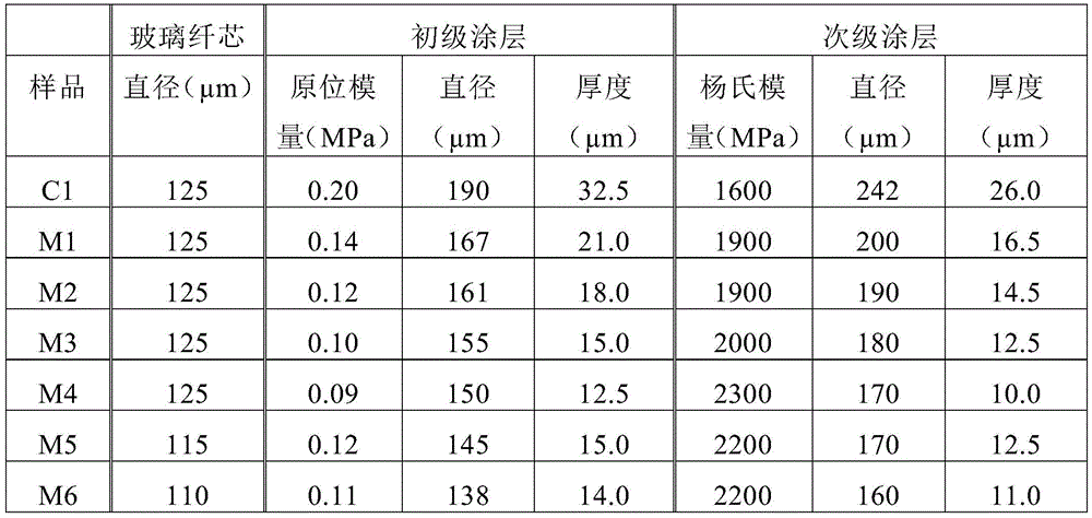
下表12总结了在玻璃纤维的外表面处的负荷P1与施加到次级涂层的表面的负荷P的比例。比例P1/P在本文中被称作负荷传输参数且对应于传输通过初级和次级涂层到达玻璃光纤表面的外部负荷P的比例。负荷P是径向负荷,并且从基于等式(9)至(11)的模型计算负荷传输参数P1/P:Table 12 below summarizes the ratio of the load P1 at the outer surface of the glass fiber to the load P applied to the surface of the secondary coating. The ratio P1/P is referred to herein as the load transfer parameter and corresponds to the ratio of the external load P transferred through the primary and secondary coatings to the surface of the glass optical fiber. The load P is a radial load, and the load transfer parameter P1/P is calculated from a model based on equations (9) to (11):

式中,In the formula,

以及as well as
B=((1-2νp(r4/r5)2+(r4/r5)2)(1-2νs(r5/r6)2+(r5/r6)2)) (11)B=((1-2ν p (r 4 /r 5 ) 2 +(r 4 /r 5 ) 2 )(1-2ν s (r 5 /r 6 ) 2 +(r 5 /r 6 ) 2 )) (11)
在等式(9)至(11)中,νp和νs是初级和次级涂层的泊松比,r4是玻璃纤维的外半径,r5是初级涂层的外半径,r6是次级涂层的外半径,Ep是初级涂层的原位模量,以及Es是次级涂层的杨氏模量。表11中的比例尺负荷传输参数P1/P(比例尺)对应于每个样品相对于比较例样品C1的比例P1/P。In equations (9) to (11), νp and νs are the Poisson's ratios of the primary and secondary coatings, r4 is the outer radius of the glass fiber, r5 is the outer radius of the primary coating, and r6 is the outer radius of the secondary coating, Ep is the in-situ modulus of the primary coating, and Es is the Young 's modulus of the secondary coating. The scale load transmission parameter P1/P (scale bar) in Table 11 corresponds to the ratio P1/P of each sample relative to the comparative sample C1.
表12:玻璃纤维表面处的负荷传输参数(P1/P)Table 12: Load transfer parameters at the glass fiber surface (P1/P)
建模实例显示尽管具有较小的涂层厚度,但是具有如本文所述的初级和次级涂层的光纤相比于具有常规厚度的常规初级和次级涂层的比较例光纤展现出玻璃纤维所经受的作用力的下降。作为结果,本文所述光纤的整体尺寸减小实现了给定尺寸光缆中更高的光纤数(或者对于给定光纤数更小的光缆直径),而没有增加由于外部作用力所导致的玻璃纤维发生破损的风险。The modeling examples show that despite having smaller coating thicknesses, optical fibers with primary and secondary coatings as described herein exhibit glass fiber A decrease in the force experienced. As a result, the reduction in the overall size of the optical fibers described herein enables a higher fiber count in a given size cable (or a smaller cable diameter for a given fiber count) without increasing the glass fiber density due to external forces. Risk of breakage.
次级涂层的比例尺负荷传输参数P1/P(比例尺)小于约0.99,或者小于约0.97,或者小于约0.95。次级涂层的负荷传输参数P1/P是:小于约0.005,或者小于0.0045,或者小于约0.00445,或者小于约0.00444,或者小于约0.0043,或者小于约0.0042,或者小于约0.0041,或者约0.005至约0.0041的范围,或者约0.0045至约0.0042的范围,或者约0.00445至约0.00420的范围,或者约0.00440至约0.004200的范围。The scale load transfer parameter P 1 /P(scale) of the secondary coating is less than about 0.99, or less than about 0.97, or less than about 0.95. The load transfer parameter P 1 /P of the secondary coating is: less than about 0.005, alternatively less than 0.0045, alternatively less than about 0.00445, alternatively less than about 0.00444, alternatively less than about 0.0043, alternatively less than about 0.0042, alternatively less than about 0.0041, alternatively about 0.005 to about 0.0041, or about 0.0045 to about 0.0042, or about 0.00445 to about 0.00420, or about 0.00440 to about 0.004200.
下表13提供了根据本公开内容实施方式的额外建模实施例。样品M7-M18是厚度减小的初级和次级涂层的实例。表12总结了对初级和次级涂层的构造进行描述的参数。Table 13 below provides additional modeling examples according to embodiments of the disclosure. Samples M7-M18 are examples of primary and secondary coatings of reduced thickness. Table 12 summarizes the parameters describing the construction of the primary and secondary coatings.
表13:建模光纤的涂层性质Table 13: Coating Properties of Modeled Optical Fibers

光纤拉制工艺Fiber Drawing Process
可以由连续光纤制造工艺形成本文公开的光纤,在其过程中,从经加热的预制件拉制玻璃纤维并尺寸调节至目标直径。然后,玻璃纤维冷却并被引导到涂覆系统,所述涂覆系统向玻璃纤维施涂液体初级涂层组合物。在向玻璃纤维施涂了液体初级涂层组合物之后,存在两种可行的加工选项。在一个加工选项中(干碰湿工艺),液体初级涂层组合物固化以形成凝固的初级涂层,液体次级涂层组合物施涂到固化的初级涂层,以及液体次级涂层组合物固化以形成凝固的次级涂层。在第二种加工选项中(湿碰湿工艺),液体次级涂层组合物施涂到液体初级涂层组合物,并且这两种液体涂层组合物同时固化以提供凝固的初级和次级涂层。在光纤离开涂覆系统之后,对光纤进行收集并室温储存。光纤的收集通常需要将光纤卷绕到卷轴上并储存卷轴。Optical fibers disclosed herein can be formed from a continuous optical fiber manufacturing process in which glass fibers are drawn from a heated preform and sized to a target diameter. The glass fibers are then cooled and directed to a coating system that applies a liquid primary coating composition to the glass fibers. After the liquid primary coating composition has been applied to the glass fibers, there are two possible processing options. In one processing option (dry-on-wet process), the liquid primary coating composition is cured to form a cured primary coating, the liquid secondary coating composition is applied to the cured primary coating, and the liquid secondary coating composition The material cures to form a solidified secondary coating. In the second processing option (wet-on-wet process), a liquid secondary coating composition is applied to a liquid primary coating composition, and the two liquid coating compositions are cured simultaneously to provide a solidified primary and secondary coating composition. coating. After the fiber exits the coating system, the fiber is collected and stored at room temperature. The collection of optical fibers typically requires winding the optical fibers onto spools and storing the spools.
在一些工艺中,涂覆系统还向次级涂层施涂第三级涂层组合物,并且使得第三级涂层组合物固化以形成固结的第三级涂层。通常来说,第三级涂层是出于鉴别目的对光纤进行标记的墨层,并且具有包含颜料以及其他方面来说与次级涂层类似的组成。将第三级涂层施涂到次级涂层并固化。通常来说,在施涂第三级涂层的时候,次级涂层已经固化了。可以在共用的连续制造工艺中施涂并固化初级、次级和第三级涂层组合物。或者,可以在共用的连续制造工艺中施涂并固化初级和次级涂层组合物,对经过涂覆的光纤进行收集,以及在分开的离线式工艺中施涂并固化第三涂层组合物以形成第三级涂层。In some processes, the coating system also applies a tertiary coating composition to the secondary coating and allows the tertiary coating composition to cure to form a consolidated tertiary coating. Typically, the tertiary coating is an ink layer that marks the fiber for identification purposes and has a composition that includes pigments and is otherwise similar to the secondary coating. A tertiary coating is applied to the secondary coating and cured. Typically, by the time the tertiary coating is applied, the secondary coating has already cured. The primary, secondary and tertiary coating compositions can be applied and cured in a common continuous manufacturing process. Alternatively, the primary and secondary coating compositions may be applied and cured in a common continuous manufacturing process, the coated optical fiber collected, and the third coating composition applied and cured in a separate off-line process to form a tertiary coating.
多纤芯光纤multi-core fiber
本文公开的光纤可用于多纤芯光纤设计。借助本公开内容的光纤,可以实现此类多纤芯光纤设计,其在较小轮廓光缆中具有最大数量的纤芯,同时维持了光纤之间的低串扰、从角落光纤到边缘的低隧道损失以及良好的弯曲性能。例如,多纤芯光纤可以包括本文公开的小轮廓光纤,每个具有掺杂了卤素和/或碱金属的纤芯以及偏移凹槽设计,如上文所讨论的那样。因此,上文所讨论的单纤芯光纤可以用于多纤芯光纤从而提供与上文所讨论相同的模场直径、有效面积和衰减。The fibers disclosed herein can be used in multi-core fiber designs. With the fibers of the present disclosure, it is possible to achieve such multi-core fiber designs with the maximum number of cores in a smaller profile cable while maintaining low crosstalk between fibers, low tunneling loss from corner fibers to edges and good bending properties. For example, multi-core optical fibers may include the low profile optical fibers disclosed herein, each having a core doped with a halogen and/or an alkali metal and an offset groove design, as discussed above. Thus, the single core fiber discussed above can be used in a multi-core fiber to provide the same mode field diameter, effective area and attenuation as discussed above.
图8A显示具有圆形轮廓的示例性多纤芯光纤80的横截面图。如图8A所示,多纤芯光纤80包括:中心光纤轴85(多纤芯光纤80的中心线),多个纤芯90,以及形成共用包层98的包层基质94。纤芯90布置在包层基质94中,每个纤芯90形成纤芯纤维CF1、CF2,它们通常延伸穿过平行于中心光纤轴85的多纤芯光纤80的长度。Figure 8A shows a cross-sectional view of an exemplary
每个纤芯90分别包括中心轴或中心线CL1和CL2以及外半径r1和r2。要注意的是,外半径r1、r2与上文关于图5所公开的半径r1相类似。如图8A所示,可以采用笛卡尔坐标来定义多纤芯光纤80内的每个中心线CL1和CL2的位置,中心光纤轴85定义了x-y坐标体系的原点(0,0),并且坐标体系由径向坐标R所限定。中心线CL1的位置可以定义为(x1,y1),以及中心线CL2的位置可以定义为(x2,y2)。然后可以将中心线CL1与CL2之间的距离DC1-C2定义为√[(x2–x1)2+(y2–y1)2]。因此,对于具有中心线CLi的给定纤芯90以及具有中心线CLj的相邻纤芯90,距离DCi-Cj定义为√[(xj–xi)2+(yj–yi)2],同样如下文更进一步讨论。Each
纤芯90可以类似于纤芯区域48且可以包括相同的材料和性质(如上文关于单纤芯光纤所讨论的那样),以及包层基质94可以类似于包层区域50且可以包括相同的材料和性质(同样如上文关于单纤芯光纤所讨论的那样)。因此,多纤芯光纤80的每个纤芯90可以被具有偏移凹槽设计的包层区域所围绕,如上文所讨论的那样。根据本公开内容的实施方式,多纤芯光纤包括:第一纤芯,围绕第一纤芯的第一内包层,第二纤芯,围绕第二纤芯的第二内包层,以及围绕第一纤芯和第二纤芯的共用包层。此外,可以在包层基质94上布置初级涂层、次级涂层和任选的第三级涂层,同样如上文所讨论的那样。The core 90 may be similar to the
虽然图8A仅显示两个纤芯90,但是多纤芯光纤80可以包括不止两个纤芯,同样如下文所述。此外,多纤芯光纤80可以包括圆形横截面轮廓(如图8A所示)或者矩形带横截面轮廓。图8B显示多纤芯光纤80的额外示例性实施方式。Although FIG. 8A shows only two
多纤芯光纤80可以以本领域已知的任意构造包含任意数量的纤芯90。例如,纤芯90的总数可以是:2至20,2至18,2至16,2至12,2至10,2至8,2至6,2至4,2至3,4至20,4至18,4至16,4至12,4至10,4至8,4至6,6至20,6至18,6至16,6至12,6至10,6至8,8至20,8至18,8至16,8至12,8至10,10至20,10至18,10至16,10至12,12至20,12至18,或者12至16。例如,纤芯90的总数可以是:2、3、4、5、6、7、8、9、10、11、12、13、14、15、16、17、18、19、20,或者任意这些值之间的任意纤芯总数。纤芯90的总数可以是偶数或者奇数,并且可以在包层基质94中以任意图案布置,其非限制性例子包括:正方形图案、矩形图案、圆形图案以及六边形格子图案。例如,图9显示包括布置成正方形图案的4根纤芯的多纤芯光纤。
如图8C所示,多纤芯光纤80中的多根纤芯90中的一个或多个被内包层95和外包层97围绕,使得外包层97围绕95,位于内包层95与共用包层98之间。每个内包层95具有外半径rIC1以及对应于纤芯90的外半径r1的内半径。内包层95具有宽度δrIC1,其由纤芯90的外半径r1和内包层95的外半径rIC1所限定。纤芯90可以具有对应于2*r1的直径d,以及内包层95可以具有对应于2*rIC1的直径dIC1。每个外包层97具有外半径rOC1以及对应于内包层95的外半径rIC1的内半径。外包层97具有宽度δrOC1,其由内包层95的外半径rIC1和外包层97的外半径rOC1所限定。要注意的是,内包层95的外半径rIC1类似于半径r2,以及外包层97的外半径rOC1类似于半径r3,如上文关于图5所讨论的那样。共用包层98具有外半径Roc,如图8A所示。As shown in FIG. 8C, one or more of the plurality of
内包层95可以类似于内包层区域51并且包括相同的材料和性质(如上文关于单纤芯光纤所讨论的那样),外包层97可以类似于凹陷折射率包层区域53并且包括相同的材料和性质(如上文关于单纤芯光纤所讨论的那样),以及共用包层98可以类似于外包层区域55并且包括相同的材料和性质(如上文关于单纤芯光纤所讨论的那样)。因此,例如外包层97可以形成凹槽区域,类似于凹陷折射率包层区域53。
参见图8A-8C,纤芯90分别具有如下范围的直径“d”(r1 x 2或者r2 x 2):约4微米至约20微米,或者约5微米至约18微米,或者约6微米至约16微米,或者约7微米至约14微米,或者约8微米至约12微米,或者约9微米至约12微米。每个纤芯90的直径d可以与多纤芯光纤80中的一个或多个其他纤芯90是相同或不同的。每个纤芯90之间的间距D可以在每个纤芯90之间是恒定的,并且可以是:约20微米或更大,或者约25微米或更大,或者约30微米或更大,或者约35微米或更大。作为补充或替代,间距D可以是:约50微米或更小,或者约45微米或更小,或者约40微米或更小,或者约35微米或更小。在一些实施方式中,间距D是如下范围:约20微米至约40微米,或者约25微米至约35微米,或者约为35微米。在其他实施方式中,两个或更多个纤芯90之间的间距可以不同于两个或更多个其他纤芯90之间的间距。纤芯90之间的间距应该足以降低纤芯之间的串扰,如下文更详细讨论。Referring to Figures 8A-8C, the
当处于带形式时,多纤芯光纤80具有横截面宽度W和厚度TH,如图8B所示。纤芯90可以沿着厚度TH布置成一行或多行以及沿着宽度W延伸的一列或多列。宽度W可以是约0.5mm至约3mm,或者约1mm至约2.5mm,或者约1mm至约2mm。厚度可以是约0.1至约0.5mm或者约0.2至0.4mm。在一个实施方式中,多纤芯光纤80具有矩形带横截面轮廓,包括8个纤芯,具有约2mm的宽度W以及约0.3mm的厚度TH。When in ribbon form,
在圆形横截面设计中,包层基质94的宽度是共用包层98的直径(Roc x 2)并且可以是:约200微米或更小,或者约150微米或更小,或者约125微米或更小,或者约80微米或更大,或者约80微米至约125微米的范围,或者约120微米至约130微米,或者约125微米。在其他实施方式中,共用包层98的直径可以是:约140微米或更大,或者约150微米或更大,或者约160微米或更大,或者约170微米或更大,或者约180微米或更大,或者约190微米或更大。作为补充或替代,共用包层98的直径可以是:约200微米或更小,或者约190微米或更小,或者约180微米或更小,或者约170微米或更小,或者约160微米或更小,或者约150微米或更小,或者约140微米或更小。在一些例子中,共用包层98的直径范围是约120微米至约140微米。In a circular cross-sectional design, the width of the
图9显示具有布置成正方形设计的4根纤芯90的示例性多纤芯光纤100。如图9所示,第一纤芯的中心线(CL1)与相邻纤芯的中心线(CL2)之间的距离D1小于约50微米,这是采用如上文所讨论的笛卡尔坐标系测得的。例如,相邻纤芯之间的距离D1可以是:大于约20微米,大于约25微米,大于约28微米,大于约30微米,大于约35微米,或者大于约40微米。作为补充或替代,距离D1可以小于约45微米,小于约40微米,或者小于约35微米。例如,距离D1可以是:约20微米至约50微米,约20微米至约45微米,约20微米至约30微米,约28微米至约50微米,约28微米至约40微米,约28微米至约30微米,约30微米至约50微米,约30微米至约40微米,或者约40微米至约45微米。对于每个纤芯,相邻纤芯90之间的距离D1可以是相同或不同的。Figure 9 shows an exemplary
在例如4x4正方形式样中,两个纤芯之间所分开的最大距离(距离D2)可以是:约20微米或更大,约25微米或更大,约30微米或更大,约35微米或更大,或者约40微米或更大。作为补充或替代,距离D2可以是:约50微米或更小,约45微米或更小,约40微米或更小,约35微米或更小,或者约30微米或更小。In, for example, a 4x4 square pattern, the maximum distance (distance D2) separated between two cores may be: about 20 microns or greater, about 25 microns or greater, about 30 microns or greater, about 35 microns or larger, or about 40 microns or larger. Additionally or alternatively, distance D2 may be: about 50 microns or less, about 45 microns or less, about 40 microns or less, about 35 microns or less, or about 30 microns or less.
同样如图9所示,纤芯90的中心线与共用包层98的外半径之间的距离D3可以是:约40微米或更小,约35微米或更小,约30微米或更小,约25微米或更小,或者约20微米或更小。作为补充或替代,距离D3可以是:约25微米或更大,约30微米或更大,约35微米或更大,约35微米或更大,或者约40微米或更大。在一些例子中,距离D3的范围是约25微米至约40微米或者约30微米至约35微米。还考虑对于每个纤芯90,距离D3可以相同或不同。As also shown in FIG. 9, the distance D3 between the centerline of the
纤芯90的外半径与共用包层98的外半径之间的距离D4可以是:约25微米或更小,约20微米或更小,约18微米或更小,约16微米或更小,约14微米或更小,约13微米或更小,约12微米或更小,约10微米或更小,约8微米或更小,或者约6微米或更小。作为补充或替代,距离D4可以是:约8微米或更大,约10微米或更大,约13微米或更大,约16微米或更大,或者约18微米或更大。在一些例子中,距离D4的范围是约10微米至约20微米或者约12微米至约16微米。还考虑对于每个纤芯90,距离D4可以相同或不同。The distance D4 between the outer radius of the
此外,如图9所示,距离D5可以是每个纤芯90的半径(例如,r1、r2)。距离D5可以是如下范围:约2微米至约30微米,或者约2.5微米至约22.5微米,或者约5微米至约20微米,或者约7微米至约14微米,或者约8微米至约12微米,或者约9微米至约11微米。例如,D5可以是:约9微米、约10微米、约10.5微米、约11微米、约11.5微米、约12微米、约12.5微米、约13微米、约14微米、约15微米、约15.5微米、约16微米、约16.5微米、约17微米、约17.5微米或者约18微米。还考虑对于每个纤芯90,距离D5可以相同或不同。Additionally, as shown in FIG. 9 , distance D5 may be the radius of each core 90 (eg, r 1 , r 2 ). Distance D5 may be in the range of about 2 microns to about 30 microns, or about 2.5 microns to about 22.5 microns, or about 5 microns to about 20 microns, or about 7 microns to about 14 microns, or about 8 microns to about 12 microns , or from about 9 microns to about 11 microns. For example, D5 can be: about 9 microns, about 10 microns, about 10.5 microns, about 11 microns, about 11.5 microns, about 12 microns, about 12.5 microns, about 13 microns, about 14 microns, about 15 microns, about 15.5 microns, About 16 microns, about 16.5 microns, about 17 microns, about 17.5 microns, or about 18 microns. It is also contemplated that distance D5 may be the same or different for each core 90 .
在一个实施方式中,示例性多纤芯光纤100包括4x4正方形设计的4纤芯区域,使得光纤的宽度W约为125微米,距离D1约为45微米,距离D2约为63.6微米,距离D3约为30.7微米,距离D4约为13微米,以及距离D5约为17.6微米。In one embodiment, exemplary
如上文所讨论的,纤芯90具有降低的串扰以确保良好的系统性能。串扰取决于纤芯之间的距离以及光纤长度。可以从等式(12)计算得到纤芯之间的平均串扰。As discussed above, the
X=2κ2LLc (12)X=2κ 2 LL c (12)
式中,k是耦合系数,L是光纤长度,以及Lc是取决于光纤均匀性和部署条件的相关性长度。where k is the coupling coefficient, L is the fiber length, and L c is the correlation length depending on the fiber uniformity and deployment conditions.
在一些实施方式中,对于运行在1550nm处的100km长度的多纤芯光纤进行测量,相邻纤芯90之间的平均串扰是:等于或小于-20dB,或者等于或小于约-30db,或者等于或小于约-35dB,或者小于约-40dB,或者小于约-45dB,或者小于约-50dB,或者等于或小于约-55dB,或者等于或小于约-60dB。In some embodiments, the average crosstalk between
图10显示沿着100km光纤长度的多纤芯光纤设计中的相邻纤芯90之间的串扰与间距图。迹线200代表具有步阶状折射率分布和80微米2有效面积的多纤芯光纤设计,迹线210代表具有(如本文所公开的)偏移凹槽设计和80微米2有效面积的多纤芯光纤设计,以及迹线220代表具有(如本文所公开的)偏移凹槽设计和100微米2有效面积的多纤芯光纤设计。如图10所示,随着纤芯之间的间距增加,迹线220的串扰低于迹线200。此外,随着纤芯之间的间距增加,迹线210的串扰低于迹线220。因此,图10显示每个纤芯具有80微米2的有效面积以及偏移凹槽设计的多纤芯设计有利地提供了相比于100微米2的有效面积的纤芯或者具有步阶状折射率分布的光纤更低的串扰。Figure 10 shows a plot of crosstalk versus spacing between
在本文公开的多纤芯光纤设计中,纤芯90在1550nm处可以具有如下衰减:小于或等于0.18dB/km,或者小于或等于0.175dB/km,或者小于或等于0.170dB/km,或者小于或等于0.165dB/km,或者小于或等于0.160dB/km,或者小于或等于0.155dB/km,或者小于或等于0.150dB/km,同样如上文所讨论的那样。每根纤芯90可以具有相同或不同的衰减。In the multi-core fiber designs disclosed herein, the
本文公开的多纤芯光纤的纤芯90可以具有小于约1500nm、小于约1400nm、小于约1300nm、小于约1260nm或者小于约1200nm的理论截止波长。例如,理论截止波长可以是约1300nm至约1500nm或者约1300nm至约1400nm。例如,理论截止波长可以是:约1300nm、约1310nm、约1320nm、约1329nm、约1330nm、约1340nm、约1350nm、约1360nm、约1370nm、约1380nm、约1400nm、约1500nm,或者这些值之间的任何理论截止波长。每根纤芯90可以具有相同或不同的理论截止波长。The
根据一个方面,纤芯90的光缆截止波长是:小于约1500nm、小于约1400nm、小于约1300nm、小于约1260nm或者小于约1200nm。例如,光缆截止波长可以是:约1200nm至约1500nm,约1200nm至约1400nm,约1200nm至约1300nm,约1300nm至约1500nm,约1300nm至约1400nm,或者约1400nm至约1500nm。例如,光缆截止波长可以是:约1200nm、约1209nm、约1210nm、约1220nm、约1230nm、约1240nm、约1250nm、约1260nm、约1300nm、约1310nm、约1350nm、约1400nm、约1410nm、约1420nm、约1430nm、约1440nm、约1450nm、约1460nm、约1500nm,或者这些值之间的任何光缆截止波长。每根纤芯90可以具有相同或不同的光缆截止波长。According to one aspect, the
根据一个方面,纤芯90可以具有约1280nm至约1340nm的零色散波长。例如,零色散波长可以是:约1290nm至约1330nm,约1295nm至约1325nm,约1300nm至约1320nm,或者约1305nm至约1315nm。例如,零色散波长可以是:约1280nm、约1285nm、约1289nm、约1290nm、约1300nm、约1301nm、约1305nm、约1306nm、约1310nm、约1315nm或者约1320nm,或者这些值之间的任何零色散波长。每根纤芯90可以具有相同或不同的零色散波长。According to one aspect,
根据本公开内容的方面,纤芯90可以具有1310nm处小于3ps/nm/km的色散绝对值以及1310nm处小于0.1ps/nm2/km的色散斜率。每根光纤90可以在1310nm处具有相同或不同的色散和色散斜率。例如,1310nm处的色散绝对值可以是:约0.3ps/nm/km至约3ps/nm/km,约0.3ps/nm/km至约2.5ps/nm/km,约0.3ps/nm/km至约2.25ps/nm/km,约0.3ps/nm/km至约2ps/nm/km,约0.3ps/nm/km至约1.75ps/nm/km,约0.3ps/nm/km至约1.5ps/nm/km,或者约0.3ps/nm/km至约1ps/nm/km。例如,1310处的色散绝对值可以是:约0.3ps/nm/km、约0.35ps/nm/km、约0.4ps/nm/km、约0.5ps/nm/km、约0.75ps/nm/km、约1ps/nm/km、约1.25ps/nm/km、约1.5ps/nm/km、约1.75ps/nm/km、约2ps/nm/km、约2.25ps/nm/km、约2.5ps/nm/km、约2.75ps/nm/km、约3ps/nm/km,或者这些值之间的任意值。在一个例子中,1310nm处的色散斜率可以是:约0.075ps/nm2/km至约0.1ps/nm2/km,约0.08ps/nm2/km至约0.1ps/nm2/km,约0.085ps/nm2/km至约0.1ps/nm2/km,约0.09ps/nm2/km至约0.1ps/nm2/km,约0.075ps/nm2/km至约0.09ps/nm2/km,约0.08ps/nm2/km至约0.09ps/nm2/km,或者约0.085ps/nm2/km至约0.09ps/nm2/km。例如,1310nm处的色散斜率可以是:约0.075ps/nm2/km、约0.08ps/nm2/km、约0.085ps/nm2/km、约0.086ps/nm2/km、约0.087ps/nm2/km、约0.088ps/nm2/km、约0.089ps/nm2/km、约0.09ps/nm2/km、约0.01ps/nm2/km,或者这些值之间的任意值。According to aspects of the present disclosure,
根据本公开内容的方面,纤芯90可以具有1550nm处小于22ps/nm/km的色散以及1550nm处小于0.1ps/nm2/km的色散斜率。每根纤芯90可以在1550nm处具有相同或不同的色散和色散斜率。例如,1550nm处的色散可以是:约10ps/nm/km至约22ps/nm/km,,约10ps/nm/km至约22ps/nm/km,约10ps/nm/km至约20ps/nm/km,约10ps/nm/km至约15ps/nm/km,约15ps/nm/km至约22ps/nm/km,或者约15ps/nm/km至约20ps/nm/km。例如,1550处的色散可以是:约10ps/nm/km、约15ps/nm/km、约16ps/nm/km、约17ps/nm/km、约17.5ps/nm/km、约18ps/nm/km、约19ps/nm/km、约19.5ps/nm/km、约19.6ps/nm/km、约20ps/nm/km、约20.1ps/nm/km、约22ps/nm/km,或者这些值之间的任意值。在一个例子中,1550nm处的色散斜率可以是:约0.04ps/nm2/km至约0.1ps/nm2/km,约0.05ps/nm2/km至约0.1ps/nm2/km,约0.055ps/nm2/km至约0.1ps/nm2/km,约0.06ps/nm2/km至约0.1ps/nm2/km,约0.08ps/nm2/km至约0.1ps/nm2/km,约0.04ps/nm2/km至约0.08ps/nm2/km,约0.05ps/nm2/km至约0.08ps/nm2/km,约0.055ps/nm2/km至约0.08ps/nm2/km,约0.06ps/nm2/km至约0.08ps/nm2/km,约0.04ps/nm2/km至约0.06ps/nm2/km,约0.05ps/nm2/km至约0.06ps/nm2/km,或者约0.055ps/nm2/km至约0.06ps/nm2/km。例如,1550nm处的色散斜率可以是:约0.04ps/nm2/km、约0.05ps/nm2/km、约0.055ps/nm2/km、约0.057ps/nm2/km、约0.058ps/nm2/km、约0.059ps/nm2/km、约0.06ps/nm2/km、约0.061ps/nm2/km、约0.07ps/nm2/km、约0.08ps/nm2/km,或者这些值之间的任意值。According to aspects of the present disclosure,
根据一个方面,通过采用10mm直径心轴的心轴缠绕测试所确定的本文公开的多纤芯光纤中的每根纤芯90在1550nm处的弯曲损耗可以是:小于约3dB/圈、小于约2.5dB/圈、小于约2dB/圈、小于约1.5dB/圈或者小于约1dB/圈。例如,采用直径10mm的心轴,弯曲损耗可以是:约0.5dB/圈至约3dB/圈,约0.5dB/圈至约2.5dB/圈,约0.5dB/圈至约2dB/圈,约0.5dB/圈至约1.5dB/圈,约0.5dB/圈至约1dB/圈,约1dB/圈至约3dB/圈,约1dB/圈至约2.5dB/圈,约1dB/圈至约2dB/圈,约1dB/圈至约1.5dB/圈,约1.5dB/圈至约3dB/圈,约1.5dB/圈至约2.5dB/圈,约1.5dB/圈至约2dB/圈,约2dB/圈至约3dB/圈,或者约2dB/圈至约2.5dB/圈。例如,采用直径10mm的心轴,弯曲损耗可以是:约0.5dB/圈、约0.75dB/圈、约0.9dB/圈、约1dB/圈、约1.5dB/圈、约2dB/圈、约2.5dB/圈、约3dB/圈,或者这些值之间的任意值。According to one aspect, the bend loss at 1550 nm for each core 90 in the multi-core optical fiber disclosed herein, as determined by mandrel winding testing using a 10 mm diameter mandrel, can be: less than about 3 dB/turn, less than about 2.5 dB/turn, less than about 2 dB/turn, less than about 1.5 dB/turn, or less than about 1 dB/turn. For example, using a mandrel with a diameter of 10mm, the bending loss can be: about 0.5dB/turn to about 3dB/turn, about 0.5dB/turn to about 2.5dB/turn, about 0.5dB/turn to about 2dB/turn, about 0.5 dB/turn to about 1.5dB/turn, about 0.5dB/turn to about 1dB/turn, about 1dB/turn to about 3dB/turn, about 1dB/turn to about 2.5dB/turn, about 1dB/turn to about 2dB/turn Turn, about 1dB/turn to about 1.5dB/turn, about 1.5dB/turn to about 3dB/turn, about 1.5dB/turn to about 2.5dB/turn, about 1.5dB/turn to about 2dB/turn, about 2dB/turn Turn to about 3dB/turn, or about 2dB/turn to about 2.5dB/turn. For example, using a mandrel with a diameter of 10mm, the bending loss can be: about 0.5dB/turn, about 0.75dB/turn, about 0.9dB/turn, about 1dB/turn, about 1.5dB/turn, about 2dB/turn, about 2.5 dB/turn, about 3dB/turn, or anything in between.
根据一个方面,通过采用15mm直径心轴的心轴缠绕测试所确定的本文公开的多纤芯光纤中的每根纤芯90在1550nm处的弯曲损耗可以是:小于约1dB/圈、小于约0.75dB/圈、小于约0.5dB/圈、或者小于约0.3dB/圈。例如,采用直径15mm的心轴,弯曲损耗可以是:约0.1dB/圈至约1dB/圈,约0.1dB/圈至约0.75dB/圈,约0.1dB/圈至约0.5dB/圈,约0.2dB/圈至约1dB/圈,约0.2dB/圈至约0.75dB/圈,约0.2dB/圈至约0.5dB/圈,约0.3dB/圈至约1dB/圈,约0.3dB/圈至约0.75dB/圈,或者约0.3dB/圈至约0.5dB/圈。例如,采用直径15mm的心轴,弯曲损耗可以是:约0.2dB/圈、约0.23dB/圈、约0.25dB/圈、约0.3dB/圈、约0.5dB/圈、约0.6dB/圈、约0.75dB/圈、约1dB/圈,或者这些值之间的任意值。According to one aspect, the bend loss at 1550 nm for each core 90 in the multi-core optical fiber disclosed herein as determined by mandrel winding testing using a 15 mm diameter mandrel may be: less than about 1 dB/turn, less than about 0.75 dB/turn, less than about 0.5 dB/turn, or less than about 0.3 dB/turn. For example, using a mandrel with a diameter of 15mm, the bending loss can be: about 0.1dB/turn to about 1dB/turn, about 0.1dB/turn to about 0.75dB/turn, about 0.1dB/turn to about 0.5dB/turn, about 0.2dB/turn to about 1dB/turn, about 0.2dB/turn to about 0.75dB/turn, about 0.2dB/turn to about 0.5dB/turn, about 0.3dB/turn to about 1dB/turn, about 0.3dB/turn to about 0.75dB/turn, or about 0.3dB/turn to about 0.5dB/turn. For example, using a mandrel with a diameter of 15mm, the bending loss can be: about 0.2dB/turn, about 0.23dB/turn, about 0.25dB/turn, about 0.3dB/turn, about 0.5dB/turn, about 0.6dB/turn, About 0.75dB/turn, about 1dB/turn, or anywhere in between.
根据一个方面,通过采用20mm直径心轴的心轴缠绕测试所确定的本文公开的多纤芯光纤中的每根纤芯90在1550nm处的弯曲损耗可以是:小于约3dB/圈、小于约2dB/圈、小于约1dB/圈、小于约0.5dB/圈、小于约0.3dB/圈或者小于约0.2dB/圈。例如,采用直径20mm的心轴,弯曲损耗可以是:约0.1dB/圈至约3dB/圈,约0.1dB/圈至约2.5dB/圈,约0.1dB/圈至约2dB/圈,约0.2dB/圈至约3dB/圈,约0.2dB/圈至约2.5dB/圈,约0.2dB/圈至约2dB/圈,约0.3dB/圈至约3dB/圈,约0.3dB/圈至约2.5dB/圈,或者约0.3dB/圈至约2dB/圈,约0.1dB/圈至约1dB/圈,约0.1dB/圈至约0.75dB/圈,约0.1dB/圈至约0.5dB/圈,0.5dB/圈至约3dB/圈,约0.5dB/圈至约2.5dB/圈,约0.5dB/圈至约2dB/圈,1dB/圈至约3dB/圈,约1dB/圈至约2.5dB/圈,或者约1dB/圈至约2dB/圈。例如,采用直径20mm的心轴,弯曲损耗可以是:约0.2dB/圈、约0.23dB/圈、约0.25dB/圈、约0.3dB/圈、约0.5dB/圈、约0.6dB/圈、约0.75dB/圈、约0.8dB/圈、约0.9dB/圈、约1dB/圈、约2dB/圈、约2.1dB/圈、约2.5dB/圈、约3dB/圈,或者这些值之间的任意值。According to one aspect, the bend loss at 1550 nm for each core 90 in the multi-core optical fiber disclosed herein, as determined by mandrel winding testing using a 20 mm diameter mandrel, can be: less than about 3 dB/turn, less than about 2 dB /turn, less than about 1 dB/turn, less than about 0.5 dB/turn, less than about 0.3 dB/turn, or less than about 0.2 dB/turn. For example, using a 20mm diameter mandrel, the bending loss can be: about 0.1dB/turn to about 3dB/turn, about 0.1dB/turn to about 2.5dB/turn, about 0.1dB/turn to about 2dB/turn, about 0.2 dB/turn to about 3dB/turn, about 0.2dB/turn to about 2.5dB/turn, about 0.2dB/turn to about 2dB/turn, about 0.3dB/turn to about 3dB/turn, about 0.3dB/turn to about 2.5dB/turn, or about 0.3dB/turn to about 2dB/turn, about 0.1dB/turn to about 1dB/turn, about 0.1dB/turn to about 0.75dB/turn, about 0.1dB/turn to about 0.5dB/turn Turn, 0.5dB/turn to about 3dB/turn, about 0.5dB/turn to about 2.5dB/turn, about 0.5dB/turn to about 2dB/turn, 1dB/turn to about 3dB/turn, about 1dB/turn to about 3dB/turn 2.5dB/turn, or about 1dB/turn to about 2dB/turn. For example, using a mandrel with a diameter of 20mm, the bending loss can be: about 0.2dB/turn, about 0.23dB/turn, about 0.25dB/turn, about 0.3dB/turn, about 0.5dB/turn, about 0.6dB/turn, About 0.75dB/turn, about 0.8dB/turn, about 0.9dB/turn, about 1dB/turn, about 2dB/turn, about 2.1dB/turn, about 2.5dB/turn, about 3dB/turn, or between these values any value of .
根据一个方面,通过采用30mm直径心轴的心轴缠绕测试所确定的本文公开的多纤芯光纤中的每根纤芯90在1550nm处的弯曲损耗可以是:小于约1dB/圈,小于约0.5dB/圈,小于约0.25dB/圈,小于约0.1dB/圈,小于约0.05dB/圈,小于约0.01dB/圈,或者小于约0.005dB/圈。例如,采用直径30mm的心轴,弯曲损耗可以是:约0.01dB/圈至约1dB/圈,约0.01dB/圈至约0.5dB/圈,约0.01dB/圈至约0.25dB/圈,约0.01dB/圈至约0.2dB/圈,约0.01dB/圈至约0.1dB/圈,约0.01dB/圈至约0.005dB/圈,约0.05dB/圈至约1dB/圈,约0.05dB/圈至约0.5dB/圈,约0.05dB/圈至约0.25dB/圈,或者约0.05dB/圈至约0.2dB/圈,约0.2dB/圈至约1dB/圈,约0.2dB/圈至约0.5dB/圈,或者约0.5dB/圈至约1dB/圈。例如,采用直径30mm的心轴,弯曲损耗可以是:约0.005dB/圈、约0.01dB/圈、约0.05dB/圈、约0.06dB/圈、约0.07dB/圈、约0.08dB/圈、约0.09dB/圈、约0.1dB/圈、约0.12dB/圈、约0.13dB/圈、约0.15dB/圈、约0.2dB/圈、约0.23dB/圈、约0.24dB/圈、约0.24dB/圈、约0.25dB/圈、约0.3dB/圈、约0.31dB/圈、约0.4dB/圈、约0.5dB/圈、约0.51dB/圈、约1dB/圈,或者这些值之间的任意值。According to one aspect, the bend loss at 1550 nm for each core 90 in the multi-core optical fiber disclosed herein as determined by mandrel winding testing using a 30 mm diameter mandrel may be: less than about 1 dB/turn, less than about 0.5 dB/turn, less than about 0.25 dB/turn, less than about 0.1 dB/turn, less than about 0.05 dB/turn, less than about 0.01 dB/turn, or less than about 0.005 dB/turn. For example, using a mandrel with a diameter of 30mm, the bending loss can be: about 0.01dB/turn to about 1dB/turn, about 0.01dB/turn to about 0.5dB/turn, about 0.01dB/turn to about 0.25dB/turn, about 0.01dB/turn to about 0.2dB/turn, about 0.01dB/turn to about 0.1dB/turn, about 0.01dB/turn to about 0.005dB/turn, about 0.05dB/turn to about 1dB/turn, about 0.05dB/turn circle to about 0.5dB/turn, about 0.05dB/turn to about 0.25dB/turn, or about 0.05dB/turn to about 0.2dB/turn, about 0.2dB/turn to about 1dB/turn, about 0.2dB/turn to about 0.2dB/turn to About 0.5dB/turn, or about 0.5dB/turn to about 1dB/turn. For example, using a mandrel with a diameter of 30mm, the bending loss can be: about 0.005dB/turn, about 0.01dB/turn, about 0.05dB/turn, about 0.06dB/turn, about 0.07dB/turn, about 0.08dB/turn, About 0.09dB/turn, about 0.1dB/turn, about 0.12dB/turn, about 0.13dB/turn, about 0.15dB/turn, about 0.2dB/turn, about 0.23dB/turn, about 0.24dB/turn, about 0.24 dB/turn, about 0.25dB/turn, about 0.3dB/turn, about 0.31dB/turn, about 0.4dB/turn, about 0.5dB/turn, about 0.51dB/turn, about 1dB/turn, or between these values any value of .
根据本公开内容的实施方式,多纤芯光纤可以具有与上文参照单纤芯光纤所讨论的相同的性质。例如,多纤芯光纤的玻璃纤芯可以具有与上文公开相同的凹槽体积、模场直径、有效面积和衰减。因此,包含本公开内容的多纤芯光纤的光纤还可以在减小轮廓的同时仍然维持长距离传输所需的足够的微弯曲和牢固度。According to embodiments of the present disclosure, multi-core fibers may have the same properties as discussed above with reference to single-core fibers. For example, the glass core of a multi-core fiber may have the same groove volume, mode field diameter, effective area, and attenuation as disclosed above. Thus, optical fibers comprising the multi-core optical fibers of the present disclosure can also reduce profile while still maintaining sufficient microbending and robustness required for long-distance transmission.
下表14提供了根据本公开内容实施方式的多纤芯光纤310-340的例子。每个多纤芯光纤310-340由布置成正方形设计的4根纤芯形成,如图9所示。光纤310-340分别具有125微米的玻璃外直径和242微米的涂层外直径。光纤310-340中的每根纤芯的半径(r1)约为17.5微米,并且每根纤芯掺杂了氯。此外,每根纤芯具有偏移凹槽设计以及布置在凹槽外侧的共用包层(如本文所公开的那样)。共用包层的折射率是-0.245%。光纤310-340中的第一纤芯的中心线与第二纤芯的中心线之间的距离D1是40微米。并且,光纤310-340中的纤芯的中心线与共用包层的外半径之间的距离D3是34.2微米。光纤310-340的光学性质如下表14所示,以及每根纤芯的相对折射率分布如图11所示。Table 14 below provides examples of multi-core optical fibers 310-340 according to embodiments of the disclosure. Each multi-core optical fiber 310-340 is formed of 4 cores arranged in a square design, as shown in FIG. 9 . Optical fibers 310-340 have glass outer diameters of 125 microns and coated outer diameters of 242 microns, respectively. The radius (r 1 ) of each core in optical fibers 310-340 is about 17.5 microns, and each core is doped with chlorine. In addition, each core has an offset groove design and a common cladding (as disclosed herein) disposed outside the groove. The refractive index of the common cladding is -0.245%. The distance D1 between the centerline of the first core and the centerline of the second core in the optical fibers 310-340 is 40 microns. Also, the distance D3 between the centerline of the core and the outer radius of the common cladding in optical fibers 310-340 is 34.2 microns. The optical properties of the optical fibers 310-340 are shown in Table 14 below, and the relative refractive index distribution of each fiber core is shown in FIG. 11 .
表14:多纤芯光纤310-340的光学性质Table 14: Optical properties of multi-core fibers 310-340

表14(续)Table 14 (continued)

除非另有表述,否则都不旨在将本文所述的任意方法理解为需要使其步骤以具体顺序进行。因此,当方法权利要求实际上没有陈述为其步骤遵循一定的顺序或者其没有在权利要求书或说明书中以任意其他方式具体表示步骤限于具体的顺序,都不旨在暗示该任意特定顺序。It is not intended that any method described herein be construed as requiring that its steps be performed in a particular order, unless otherwise stated. Thus, when a method claim does not actually state that its steps follow a certain order or that it does not in any other way specifically indicate that the steps are limited to a specific order in the claims or specification, it is not intended to imply any particular order.
对本领域的技术人员而言,显而易见的是可以在不偏离本发明的范围或精神的情况下进行各种修改和变动。因为本领域的技术人员可以想到所述实施方式的融合了本发明精神和实质的各种改良组合、子项组合和变化,应认为本发明包括所附权利要求书范围内的全部内容及其等同内容。It will be apparent to those skilled in the art that various modifications and changes can be made without departing from the scope or spirit of the invention. Because those skilled in the art can think of various improved combinations, sub-item combinations and changes of the embodiments that incorporate the spirit and essence of the present invention, it should be considered that the present invention includes all content within the scope of the appended claims and their equivalents. content.
Claims (49)
Applications Claiming Priority (5)
| Application Number | Priority Date | Filing Date | Title |
|---|---|---|---|
| US202062991231P | 2020-03-18 | 2020-03-18 | |
| US62/991,231 | 2020-03-18 | ||
| NL2025269A NL2025269B1 (en) | 2020-03-18 | 2020-04-03 | Reduced diameter optical fiber with improved microbending |
| NL2025269 | 2020-04-03 | ||
| PCT/US2021/020211 WO2021188289A1 (en) | 2020-03-18 | 2021-03-01 | Reduced diameter optical fiber with improved microbending |
Publications (1)
| Publication Number | Publication Date |
|---|---|
| CN115552298A true CN115552298A (en) | 2022-12-30 |
Family
ID=74858375
Family Applications (1)
| Application Number | Title | Priority Date | Filing Date |
|---|---|---|---|
| CN202180033265.XA Pending CN115552298A (en) | 2020-03-18 | 2021-03-01 | Reduced diameter optical fiber with improved microbending |
Country Status (5)
| Country | Link |
|---|---|
| US (2) | US11874494B2 (en) |
| EP (1) | EP3882676A1 (en) |
| JP (1) | JP7789457B2 (en) |
| CN (1) | CN115552298A (en) |
| WO (1) | WO2021188289A1 (en) |
Families Citing this family (15)
| Publication number | Priority date | Publication date | Assignee | Title |
|---|---|---|---|---|
| CN111965753A (en) * | 2019-08-13 | 2020-11-20 | 斯特里特技术有限公司 | Reduced diameter optical fiber |
| US11822117B2 (en) * | 2019-10-08 | 2023-11-21 | Corning Incorporated | Primary coating compositions with improved microbending performance |
| US11874494B2 (en) * | 2020-03-18 | 2024-01-16 | Corning Incorporated | Reduced diameter optical fiber with improved microbending |
| CN115515909B (en) * | 2020-05-08 | 2024-09-24 | 康宁股份有限公司 | Slow cooling of optical fibers with halogen-doped cores |
| US12032200B2 (en) * | 2021-12-28 | 2024-07-09 | Sterlite Technologies Limited | Trench assisted multi-core optical fiber with reduced crosstalk |
| EP4481450A4 (en) * | 2022-02-16 | 2025-06-18 | Sumitomo Electric Industries, Ltd. | OPTICAL FIBER |
| US12535637B2 (en) * | 2022-08-12 | 2026-01-27 | Corning Incorporated | Uncoupled multicore optical fiber with alkali doped, off-set trench cores |
| US20240069271A1 (en) * | 2022-08-26 | 2024-02-29 | Corning Incorporated | Uncoupled-core multicore optical fiber with reduced cross talk |
| JPWO2024122510A1 (en) * | 2022-12-07 | 2024-06-13 | ||
| WO2024150692A1 (en) * | 2023-01-11 | 2024-07-18 | 住友電気工業株式会社 | Optical fiber |
| US20240411081A1 (en) * | 2023-06-06 | 2024-12-12 | Corning Research & Development Corporation | Multicore optical fiber system connectivity in data centers |
| US12436647B2 (en) * | 2023-06-30 | 2025-10-07 | Apple Inc. | Systems and methods to control cross-talk of an optical fiber-based sensing module |
| EP4485022A1 (en) * | 2023-06-30 | 2025-01-01 | Sterlite Technologies Limited | Optical fiber cable and optical fiber with reduced diameter |
| US20250172747A1 (en) * | 2023-11-28 | 2025-05-29 | Corning Incorporated | Uncoupled multicore optical fiber with alkali doped cores |
| WO2026009957A1 (en) * | 2024-07-05 | 2026-01-08 | 住友電気工業株式会社 | Optical fiber |
Family Cites Families (29)
| Publication number | Priority date | Publication date | Assignee | Title |
|---|---|---|---|---|
| US20070003198A1 (en) * | 2005-06-29 | 2007-01-04 | Lance Gibson | Low loss optical fiber designs and methods for their manufacture |
| US7272289B2 (en) | 2005-09-30 | 2007-09-18 | Corning Incorporated | Low bend loss optical fiber |
| US7844155B2 (en) | 2007-05-07 | 2010-11-30 | Corning Incorporated | Optical fiber containing alkali metal oxide |
| ES2480190T3 (en) | 2007-11-09 | 2014-07-25 | Draka Comteq B.V. | Microcurvature resistant fiber optic |
| JP5588451B2 (en) | 2008-11-07 | 2014-09-10 | ドラカ・コムテツク・ベー・ベー | Small diameter optical fiber |
| US8467649B2 (en) * | 2009-11-30 | 2013-06-18 | Corning Incorporated | Large effective area fiber |
| US8538219B2 (en) | 2010-10-29 | 2013-09-17 | Corning Incorporated | Large effective area optical fiber with low bend loss |
| US8731357B2 (en) * | 2011-09-23 | 2014-05-20 | Sumitomo Electric Industries, Ltd. | Optical fiber |
| US9057817B2 (en) * | 2013-04-15 | 2015-06-16 | Corning Incorporated | Low diameter optical fiber |
| US9804326B2 (en) | 2015-06-23 | 2017-10-31 | Corning Incorporated | Optical fiber for multimode and single-mode transmission |
| US9851501B2 (en) | 2016-03-29 | 2017-12-26 | Corning Incorporated | Low bend loss optical fiber |
| US9995873B2 (en) * | 2016-07-29 | 2018-06-12 | Corning Incorporated | Single-mode large effective area optical fibers |
| WO2018022411A1 (en) * | 2016-07-29 | 2018-02-01 | Corning Incorporated | Low loss single mode fiber with chlorine doped core |
| US10162109B2 (en) * | 2017-02-07 | 2018-12-25 | Corning Incorporated | Multimode optical fibers for attenuators |
| JP6951852B2 (en) | 2017-03-27 | 2021-10-20 | 古河電気工業株式会社 | Optical fiber and manufacturing method of optical fiber |
| US11161767B2 (en) * | 2018-01-25 | 2021-11-02 | Ofs Fitel, Llc | Viscocity-reducing dopants in optical fibers |
| US11181686B2 (en) | 2018-04-30 | 2021-11-23 | Corning Incorporated | Small diameter low attenuation optical fiber |
| JP2021523397A (en) * | 2018-04-30 | 2021-09-02 | コーニング インコーポレイテッド | Small outer diameter low attenuation optical fiber |
| WO2020027063A1 (en) | 2018-07-31 | 2020-02-06 | 住友電気工業株式会社 | Optical fiber |
| US11194107B2 (en) * | 2019-08-20 | 2021-12-07 | Corning Incorporated | High-density FAUs and optical interconnection devices employing small diameter low attenuation optical fiber |
| JP7740806B2 (en) * | 2020-01-07 | 2025-09-17 | コーニング インコーポレイテッド | Reduced radius optical fiber with high mechanical reliability. |
| WO2021188288A1 (en) * | 2020-03-18 | 2021-09-23 | Corning Incorporated | Reduced diameter optical fiber with improved microbending |
| US11874494B2 (en) * | 2020-03-18 | 2024-01-16 | Corning Incorporated | Reduced diameter optical fiber with improved microbending |
| WO2021231085A1 (en) * | 2020-05-12 | 2021-11-18 | Corning Incorporated | Reduced diameter multimode optical fibers with high mechanical reliability |
| WO2021231084A1 (en) * | 2020-05-12 | 2021-11-18 | Corning Incorporated | Single mode optical fibers with low cutoff wavelength and high mechanical reliability |
| WO2021231083A1 (en) * | 2020-05-12 | 2021-11-18 | Corning Incorporated | Reduced diameter single mode optical fibers with high mechanical reliability |
| JP2023536418A (en) * | 2020-07-21 | 2023-08-25 | コーニング インコーポレイテッド | Single-mode optical fiber with thin coating for high-density cables and interconnects |
| US11733449B2 (en) * | 2020-08-10 | 2023-08-22 | Corning Incorporated | Ultra-low-loss coupled-core multicore optical fibers |
| US20220283363A1 (en) * | 2021-03-03 | 2022-09-08 | Corning Incorporated | Optical fiber with reduced attenuation due to reduced absorption contribution |
-
2021
- 2021-02-25 US US17/184,909 patent/US11874494B2/en active Active
- 2021-03-01 WO PCT/US2021/020211 patent/WO2021188289A1/en not_active Ceased
- 2021-03-01 CN CN202180033265.XA patent/CN115552298A/en active Pending
- 2021-03-01 JP JP2022556071A patent/JP7789457B2/en active Active
- 2021-03-12 EP EP21162261.8A patent/EP3882676A1/en active Pending
-
2023
- 2023-10-12 US US18/379,476 patent/US12105322B2/en active Active
Also Published As
| Publication number | Publication date |
|---|---|
| WO2021188289A1 (en) | 2021-09-23 |
| US12105322B2 (en) | 2024-10-01 |
| US20240045138A1 (en) | 2024-02-08 |
| EP3882676A1 (en) | 2021-09-22 |
| US11874494B2 (en) | 2024-01-16 |
| US20210294029A1 (en) | 2021-09-23 |
| JP7789457B2 (en) | 2025-12-22 |
| JP2023518942A (en) | 2023-05-09 |
Similar Documents
| Publication | Publication Date | Title |
|---|---|---|
| CN115552298A (en) | Reduced diameter optical fiber with improved microbending | |
| CN115516349A (en) | Reduced diameter optical fiber with improved microbending | |
| US11448842B2 (en) | Small diameter fiber optic cables having low-friction cable jackets and optical fibers with reduced cladding and coating diameters | |
| KR102306086B1 (en) | Low diameter optical fiber | |
| US11782207B2 (en) | Single-mode optical fiber with thin coating for high density cables and interconnects | |
| US8031997B2 (en) | Reduced-diameter, easy-access loose tube cable | |
| US8041168B2 (en) | Reduced-diameter ribbon cables with high-performance optical fiber | |
| US8467650B2 (en) | High-fiber-density optical-fiber cable | |
| CN114746783B (en) | Optical fiber with low macrobending loss at large bending diameters | |
| US20210055490A1 (en) | High-density faus and optical interconnection devices employing small diameter low attenuation optical fiber | |
| US11656403B2 (en) | Single mode optical fibers with low cutoff wavelength high mechanical reliability | |
| US11733453B2 (en) | Reduced diameter single mode optical fibers with high mechanical reliability | |
| WO2021231085A1 (en) | Reduced diameter multimode optical fibers with high mechanical reliability | |
| US20240210643A1 (en) | Intermittently bonded optical fiber ribbon with reduced diameter fibers | |
| CN112654908A (en) | Optical fiber core wire and optical fiber cable | |
| NL2025269B1 (en) | Reduced diameter optical fiber with improved microbending | |
| NL2025271B1 (en) | Reduced diameter optical fiber with improved microbending |
Legal Events
| Date | Code | Title | Description |
|---|---|---|---|
| PB01 | Publication | ||
| PB01 | Publication | ||
| WD01 | Invention patent application deemed withdrawn after publication | ||
| WD01 | Invention patent application deemed withdrawn after publication |
Application publication date: 20221230 |