CN115534353A - Manufacturing process of composite material axle shell assembly for automobile chassis - Google Patents
Manufacturing process of composite material axle shell assembly for automobile chassis Download PDFInfo
- Publication number
- CN115534353A CN115534353A CN202210544725.1A CN202210544725A CN115534353A CN 115534353 A CN115534353 A CN 115534353A CN 202210544725 A CN202210544725 A CN 202210544725A CN 115534353 A CN115534353 A CN 115534353A
- Authority
- CN
- China
- Prior art keywords
- housing
- prepreg
- shell
- manufacturing process
- automobile chassis
- Prior art date
- Legal status (The legal status is an assumption and is not a legal conclusion. Google has not performed a legal analysis and makes no representation as to the accuracy of the status listed.)
- Pending
Links
Images


Classifications
-
- B—PERFORMING OPERATIONS; TRANSPORTING
- B29—WORKING OF PLASTICS; WORKING OF SUBSTANCES IN A PLASTIC STATE IN GENERAL
- B29C—SHAPING OR JOINING OF PLASTICS; SHAPING OF MATERIAL IN A PLASTIC STATE, NOT OTHERWISE PROVIDED FOR; AFTER-TREATMENT OF THE SHAPED PRODUCTS, e.g. REPAIRING
- B29C70/00—Shaping composites, i.e. plastics material comprising reinforcements, fillers or preformed parts, e.g. inserts
- B29C70/04—Shaping composites, i.e. plastics material comprising reinforcements, fillers or preformed parts, e.g. inserts comprising reinforcements only, e.g. self-reinforcing plastics
- B29C70/28—Shaping operations therefor
- B29C70/30—Shaping by lay-up, i.e. applying fibres, tape or broadsheet on a mould, former or core; Shaping by spray-up, i.e. spraying of fibres on a mould, former or core
- B29C70/34—Shaping by lay-up, i.e. applying fibres, tape or broadsheet on a mould, former or core; Shaping by spray-up, i.e. spraying of fibres on a mould, former or core and shaping or impregnating by compression, i.e. combined with compressing after the lay-up operation
-
- B—PERFORMING OPERATIONS; TRANSPORTING
- B29—WORKING OF PLASTICS; WORKING OF SUBSTANCES IN A PLASTIC STATE IN GENERAL
- B29B—PREPARATION OR PRETREATMENT OF THE MATERIAL TO BE SHAPED; MAKING GRANULES OR PREFORMS; RECOVERY OF PLASTICS OR OTHER CONSTITUENTS OF WASTE MATERIAL CONTAINING PLASTICS
- B29B15/00—Pretreatment of the material to be shaped, not covered by groups B29B7/00 - B29B13/00
- B29B15/08—Pretreatment of the material to be shaped, not covered by groups B29B7/00 - B29B13/00 of reinforcements or fillers
- B29B15/10—Coating or impregnating independently of the moulding or shaping step
-
- B—PERFORMING OPERATIONS; TRANSPORTING
- B29—WORKING OF PLASTICS; WORKING OF SUBSTANCES IN A PLASTIC STATE IN GENERAL
- B29C—SHAPING OR JOINING OF PLASTICS; SHAPING OF MATERIAL IN A PLASTIC STATE, NOT OTHERWISE PROVIDED FOR; AFTER-TREATMENT OF THE SHAPED PRODUCTS, e.g. REPAIRING
- B29C33/00—Moulds or cores; Details thereof or accessories therefor
- B29C33/38—Moulds or cores; Details thereof or accessories therefor characterised by the material or the manufacturing process
- B29C33/3835—Designing moulds, e.g. using CAD-CAM
-
- B—PERFORMING OPERATIONS; TRANSPORTING
- B29—WORKING OF PLASTICS; WORKING OF SUBSTANCES IN A PLASTIC STATE IN GENERAL
- B29C—SHAPING OR JOINING OF PLASTICS; SHAPING OF MATERIAL IN A PLASTIC STATE, NOT OTHERWISE PROVIDED FOR; AFTER-TREATMENT OF THE SHAPED PRODUCTS, e.g. REPAIRING
- B29C33/00—Moulds or cores; Details thereof or accessories therefor
- B29C33/56—Coatings, e.g. enameled or galvanised; Releasing, lubricating or separating agents
- B29C33/58—Applying the releasing agents
-
- B—PERFORMING OPERATIONS; TRANSPORTING
- B29—WORKING OF PLASTICS; WORKING OF SUBSTANCES IN A PLASTIC STATE IN GENERAL
- B29C—SHAPING OR JOINING OF PLASTICS; SHAPING OF MATERIAL IN A PLASTIC STATE, NOT OTHERWISE PROVIDED FOR; AFTER-TREATMENT OF THE SHAPED PRODUCTS, e.g. REPAIRING
- B29C70/00—Shaping composites, i.e. plastics material comprising reinforcements, fillers or preformed parts, e.g. inserts
- B29C70/04—Shaping composites, i.e. plastics material comprising reinforcements, fillers or preformed parts, e.g. inserts comprising reinforcements only, e.g. self-reinforcing plastics
- B29C70/28—Shaping operations therefor
- B29C70/54—Component parts, details or accessories; Auxiliary operations, e.g. feeding or storage of prepregs or SMC after impregnation or during ageing
- B29C70/545—Perforating, cutting or machining during or after moulding
-
- B—PERFORMING OPERATIONS; TRANSPORTING
- B29—WORKING OF PLASTICS; WORKING OF SUBSTANCES IN A PLASTIC STATE IN GENERAL
- B29L—INDEXING SCHEME ASSOCIATED WITH SUBCLASS B29C, RELATING TO PARTICULAR ARTICLES
- B29L2031/00—Other particular articles
- B29L2031/30—Vehicles, e.g. ships or aircraft, or body parts thereof
Landscapes
- Engineering & Computer Science (AREA)
- Mechanical Engineering (AREA)
- Chemical & Material Sciences (AREA)
- Composite Materials (AREA)
- Manufacturing & Machinery (AREA)
- Moulding By Coating Moulds (AREA)
Abstract
本发明涉及汽车领域,特指一种用于汽车底盘的复合材料车桥壳体总成制作工艺,车桥壳体包括减速器壳体、后盖壳体和半轴壳体,减速器壳体和后盖壳体通过预浸料模压成型工艺,半轴壳体通过缠绕成型工艺,该制备工艺速度快,效率高,且制成的车桥壳体具有轻量化,高强度,不易生锈的特点。

The invention relates to the field of automobiles, in particular to a manufacturing process for a composite axle housing assembly used in an automobile chassis. The axle housing includes a reducer housing, a rear cover housing and a half shaft housing. The reducer housing And the rear cover shell is molded through prepreg molding process, and the half shaft shell is wound through the winding molding process. features.
Description
技术领域technical field
本发明涉及汽车领域,特指一种用于汽车底盘的复合材料车桥壳体总成制 作工艺。The invention relates to the field of automobiles, in particular to a manufacturing process of a composite axle housing assembly used for an automobile chassis.
背景技术Background technique
车桥作为汽车底盘的重要结构之一,它依靠悬架与车架相连,在其两侧安装着轮胎,其作用是支撑汽车质量,并承受由车轮传来的路面反力和反力矩,并经悬架传给车架。汽车桥壳作为车桥的主体部分,是保证汽车正常运行和使用寿命的关键部件,对其强度、刚度和耐疲劳性能都有要求。若在汽车行驶过程中壳体发生断裂,则会使车身的承载能力下降,进而诱发安全事故。因此,车桥壳体对行车安全及整车的舒适性都有非常关键的影响。目前汽车采用的车桥壳体大多数用铸钢制成,其质量较高,对燃油效率和续航能力会产生影响。As one of the important structures of the automobile chassis, the axle is connected to the frame by means of the suspension, and tires are installed on both sides of the axle. Passed to the frame through the suspension. As the main part of the axle, the automobile axle housing is a key component to ensure the normal operation and service life of the automobile, and has requirements for its strength, stiffness and fatigue resistance. If the casing breaks during the running of the vehicle, the load-carrying capacity of the vehicle body will be reduced, thereby causing safety accidents. Therefore, the axle housing has a very critical influence on the driving safety and the comfort of the vehicle. At present, most of the axle housings used in automobiles are made of cast steel, which is of high quality and will have an impact on fuel efficiency and endurance.
因此,本发明人对此做进一步研究,研发出一种用于汽车底盘的复合材料 车桥壳体总成制作工艺,本案由此产生。Therefore, the inventor does further research on this, develops a kind of composite material axle housing assembly manufacturing process that is used for automobile chassis, and this case results from this.
发明内容Contents of the invention
本发明的目的在于提供一种用于汽车底盘的复合材料车桥壳体总成制作工 艺,该制备方法速度快,效率高,且制成的车桥壳体具有轻量化,高强度,不 易生锈的特点。The purpose of the present invention is to provide a composite material axle housing assembly manufacturing process for automobile chassis. characteristics of rust.
为了实现上述目的,本发明的技术方案如下:In order to achieve the above object, the technical scheme of the present invention is as follows:
一种用于汽车底盘的复合材料车桥壳体总成制作工艺,车桥壳体包括减速 器壳体、后盖壳体和半轴壳体,减速器壳体和后盖壳体通过预浸料模压成型工 艺,半轴壳体通过缠绕成型工艺,具体制备方法步骤如下:A manufacturing process for a composite axle housing assembly used in an automobile chassis. The axle housing includes a reducer housing, a rear cover housing and a half shaft housing. The reducer housing and the rear cover housing are prepreg Material compression molding process, half-shaft shell through winding molding process, the specific preparation method steps are as follows:
减速器壳体、后盖壳体成型工艺包括:The molding process of the reducer housing and the rear cover housing includes:
步骤A1、对壳体的载荷分析,并进行铺层设计:根据减速器壳体与后盖壳 体在工作时的受载情况计算出在壳体在弯曲时承受的最大弯曲载荷力的分布情 况,选取材料以及铺层设计保证达到所需要的强度与刚度;Step A1, analyze the load of the shell, and carry out the lay-up design: calculate the distribution of the maximum bending load when the shell is bent according to the loading conditions of the reducer shell and the rear cover shell during work , select materials and lay-up design to ensure the required strength and stiffness;
步骤A2、模具的设计:准备内腔形状与减速器壳体、后盖壳体相对应的模具, 模具腔内与减速器壳体相对应的部分为减速器壳体腔、与后盖壳体相对应的部 分为后盖壳体腔,用白色干净棉布蘸取脱模剂,对成型模具型腔进行全面擦涂, 同时将模具预热至40℃-60℃;Step A2, the design of the mould: prepare the mold corresponding to the shape of the inner cavity and the reducer housing and the back cover housing, the part corresponding to the reducer housing in the mold cavity is the reducer housing cavity, and the part corresponding to the back cover housing The corresponding part is the housing cavity of the back cover. Use a white clean cotton cloth to dip the release agent, wipe the mold cavity completely, and preheat the mold to 40°C-60°C;
步骤A3、预浸料的准备:根据减速器壳体、后盖壳体的形状剪裁备用的碳纤 维与玄武岩纤维织物,然后将上述纤维织物与树脂混合得到预浸料、并在40℃ 下预热;Step A3, preparation of prepreg: cut the spare carbon fiber and basalt fiber fabric according to the shape of the reducer housing and the rear cover housing, then mix the above fiber fabric with resin to obtain prepreg, and preheat at 40°C ;
步骤A4、壳体的成型:将预热完的预浸料按设计的方案铺设在模具中,预浸 料在压力作用下浸渍、流动并充满模腔,最终经保压冷却,脱模即可完成成型;Step A4, molding of the shell: Lay the preheated prepreg in the mold according to the designed plan, the prepreg is impregnated, flows and fills the mold cavity under pressure, and finally it is cooled under pressure and demoulded complete molding;
步骤A5、成型后处理:脱模后对制品进行修边以及冲孔的处理得到最终制 品;Step A5, post-molding treatment: trimming and punching the product after demoulding to obtain the final product;
半轴壳体制备步骤如下:The preparation steps of the half shaft shell are as follows:
步骤B1、对壳体载荷分析并进行铺层设:根据半轴壳体受载情况计算出半轴 在扭转时承受的最大扭转力的分布情况,选取纤维材料以及进行铺层设计;Step B1, shell load analysis and lay-up design: calculate the distribution of the maximum torsional force that the half-shaft bears when torsioned according to the loaded situation of the half-shaft shell, select fiber materials and carry out lay-up design;
步骤B2、芯模制造及制配缠绕机:制备所需尺寸的钢材芯模,并调整好缠绕 机系统;Step B2, mandrel manufacturing and winding machine: prepare the steel mandrel of required size, and adjust the winding machine system;
步骤B3、预浸带的制备:将增强纤维放置在缠绕机的树脂槽内,然后注入树 脂与纤维充分混合;Step B3, the preparation of prepreg tape: reinforcing fiber is placed in the resin tank of winding machine, then inject resin and fully mix with fiber;
步骤B4、预浸带的缠绕:芯模在驱动控制系统的控制下,按既定的转速旋转, 树脂槽按设定的速度来回行走,使得预浸带按螺旋形的排布在芯模上;Step B4, winding of the prepreg tape: the mandrel rotates at a predetermined speed under the control of the drive control system, and the resin tank travels back and forth at a set speed, so that the prepreg tape is arranged on the mandrel in a spiral;
步骤B5、预浸带的固化:将缠绕在芯模上的预浸带放入恒温箱中,设定温度 和时间进行固化;Step B5, the curing of prepreg tape: the prepreg tape wound on the mandrel is put into the incubator, set temperature and time to cure;
步骤B6、固化后处理。Step B6, post-curing treatment.
进一步,步骤A2中,模具采用圆角设计;步骤A3中,树脂选择环氧树脂。Further, in step A2, the mold adopts a rounded corner design; in step A3, epoxy resin is selected as the resin.
进一步,步骤A2中,增加对减速器壳体与半轴连接处的设计,采用花键连 接加胶黏剂连接的方式,内花键共有8个键槽,同时设置有三条加强筋,胶黏 剂选择3M DP460结构胶。Further, in step A2, increase the design of the connection between the reducer housing and the half shaft, and adopt the method of spline connection and adhesive connection. Choose 3M DP460 structural adhesive.
进一步,步骤A4中,将预浸料预热后立即铺设在预热完的模具中。Further, in step A4, the prepreg is immediately laid in the preheated mold after preheating.
进一步,步骤A2中,减速器壳体中,采用金属花键与复合材料壳体通过胶 黏剂连接与铰接连接的方式与壳体连接,对于复合材料加强筋与金属花键采用 胶粘剂连接的方式,胶粘剂选择3M DP460结构胶。Further, in step A2, in the reducer housing, the metal spline and the composite material housing are connected to the housing by means of adhesive connection and hinged connection, and the composite material reinforcing rib and the metal spline are connected by adhesive , Adhesive selection 3M DP460 structural adhesive.
进一步,步骤A4中,减速器壳体内表面按照0°铺层角度铺设30层,加强 筋按照45°铺层角度铺设50层,圆柱接口采用±45°铺层角度铺设40层,减速器 壳体其余外表面按照0°/45°/-45°/0°铺层角度铺设40层,后盖壳体按照 0°/45°/-45°的铺层顺序铺设30层。为了减少后盖壳体开孔处的应力集中, 在开孔处增加10层±45°铺层角度的预浸料,保证开孔的可靠性。Further, in step A4, 30 layers are laid on the inner surface of the reducer housing at a lay-up angle of 0°, 50 layers of reinforcing ribs are laid at a lay-up angle of 45°, and 40 layers are laid at a cylindrical interface at a lay-up angle of ±45°. Lay 40 layers on the remaining outer surface according to the laying angle of 0°/45°/-45°/0°, and lay 30 layers on the rear cover shell according to the laying sequence of 0°/45°/-45°. In order to reduce the stress concentration at the opening of the rear cover shell, 10 layers of prepreg with a layup angle of ±45° are added to the opening to ensure the reliability of the opening.
进一步,步骤B1中,采用45°/-45°的铺层铺设30层。Further, in step B1, 30 layers are laid using a 45°/-45° layup.
进一步,步骤B2中,芯模的端部连接处采用外花键连接加胶黏剂连接的方 式,外花键有8个键槽,胶黏剂选择3M DP460结构胶Further, in step B2, the connection at the end of the mandrel adopts an external spline connection and an adhesive connection, the external spline has 8 key grooves, and the adhesive is 3M DP460 structural adhesive
进一步,步骤B3中,预浸料的制备时控制温度使残余溶剂除去,同时不能 使预浸带固化和产生气泡。Further, in step B3, during the preparation of the prepreg, the temperature is controlled so that the residual solvent is removed, and the prepreg tape cannot be solidified and bubbles can not be generated simultaneously.
进一步,步骤A4中,固化后将金属内花键通过胶粘剂和铰接方式将内花键 与壳体内外表面连接,圆柱接口采用胶粘剂的方式与壳体连接,加强筋采用胶 粘剂连接的方式与花键与壳体外表面连接。Further, in step A4, after curing, the metal internal spline is connected to the inner and outer surfaces of the housing through adhesive and hinged joints, the cylindrical interface is connected to the housing by adhesive, and the reinforcing rib is connected to the spline by adhesive Connected to the outer surface of the shell.
进一步,步骤B5中,将金属外花键与缠绕在芯模上的预浸带采用胶粘剂的 方式连接,然后放入恒温箱中进行固化。Further, in step B5, the metal external spline is connected with the prepreg tape wound on the mandrel by means of an adhesive, and then put into a constant temperature box for curing.
采用上述方案后,本发明与现有技术相比,具有以下优点:After adopting the above scheme, the present invention has the following advantages compared with the prior art:
复合材料的车桥壳体总成是采用纤维增强树脂基复合材料制作的车桥壳 体,在相同刚度的前提下,复合材料车桥壳体总成的重量可比金属车桥壳体总 成轻40%以上,此外,由于复合材料具有比强度、比模量高,不生锈,耐疲劳性 能好,阻尼减震性能好等优越特性,因此复合材料车桥壳体的承载能力以及储 能能力也比金属车桥壳体好;复合材料车桥壳体的综合性能明显优于金属车桥 壳体,具有良好的应用前景。The composite axle housing assembly is an axle housing made of fiber-reinforced resin-based composite materials. Under the premise of the same rigidity, the weight of the composite axle housing assembly is lighter than that of the metal axle housing assembly. In addition, due to the superior characteristics of composite materials such as high specific strength and specific modulus, no rust, good fatigue resistance, and good damping and shock absorption performance, the bearing capacity and energy storage capacity of the composite axle housing It is also better than the metal axle housing; the overall performance of the composite axle housing is obviously better than that of the metal axle housing, and has a good application prospect.
附图说明Description of drawings
图1为本发明车桥壳体总成结构示意图;Fig. 1 is a schematic diagram of the structure of the axle housing assembly of the present invention;
图2为减速器壳体结构示意图;Figure 2 is a schematic diagram of the structure of the reducer housing;
图3为半轴壳体结构示意图;Fig. 3 is a schematic diagram of the structure of the half shaft housing;
图4为后盖壳体结构示意图;Fig. 4 is a schematic diagram of the structure of the rear cover shell;
图5为模压成型工艺流程图;Fig. 5 is a flow chart of the molding process;
图6为缠绕成型工艺流程图;Fig. 6 is a winding forming process flow chart;
图7为半轴壳体横截面示意图;Figure 7 is a schematic cross-sectional view of the half shaft housing;
标号说明Label description
半轴壳体1,减速器壳体2,后盖壳体3,加强筋4,内花键5,外花键6, 平纹布7。
具体实施方式detailed description
下面结合附图和具体实施例对本发明作进一步的说明。The present invention will be further described below in conjunction with the accompanying drawings and specific embodiments.
如图1所示,一种复合材料车桥壳体由减速器壳体、半轴壳体、后盖壳体组成,所述复合材料由热塑性树脂为基体,玄武岩、碳纤维或玻璃纤维为增强纤维组成。As shown in Figure 1, a composite axle housing is composed of a reducer housing, a half shaft housing, and a rear cover housing. The composite material is made of thermoplastic resin as a matrix, and basalt, carbon fiber or glass fiber is a reinforcing fiber. composition.
在模压工艺过程中,为了保证复合材料的性能不受影响,对模具和预浸料 进行提前预热,同时在铺设时要尽快,以减少和空气接触时间。During the molding process, in order to ensure that the performance of the composite material is not affected, the mold and prepreg should be preheated in advance, and the laying should be done as soon as possible to reduce the contact time with air.
如图2、4所示,为了避免在铺设时损坏纤维,影响预浸料的质量最终影响 到最终模压制品的性能,对直线边处采用了圆角的设计。As shown in Figures 2 and 4, in order to avoid damaging the fibers during laying, affecting the quality of the prepreg and ultimately affecting the performance of the final molded product, rounded corners are used on the straight edges.
如图2、3所示,为了保证壳体连接可靠性,在半轴与减速器的连接处采用 了花键连接的方式,内外花键各有8个键槽,增大接触面积,提高承载能力同 时还增加3个加强筋以增大壳体的刚度与强度,并且为了加强连接效果,同时 采用3M DP460结构胶进行胶接,该胶黏剂在固化时会膨胀,能使连接效果更好 且该胶的断裂应变较大,而且能够承受较高的疲劳极限应力,增大疲劳寿命, 提高连接的可靠性。As shown in Figures 2 and 3, in order to ensure the reliability of the connection of the shell, a spline connection is adopted at the connection between the half shaft and the reducer. The inner and outer splines each have 8 key grooves to increase the contact area and improve the bearing capacity. At the same time, three reinforcing ribs are added to increase the rigidity and strength of the shell, and in order to strengthen the connection effect, 3M DP460 structural adhesive is used for bonding at the same time. The adhesive will expand when it is cured, which can make the connection effect better and The adhesive has a large fracture strain, and can bear a high fatigue limit stress, thereby increasing the fatigue life and improving the reliability of the connection.
在模压工艺中,为了保证模具和最终成品的质量,需要用白色干净棉布蘸 取脱模剂,对成型模具型腔进行全面擦涂,如此进行3~5遍,每次时间间隔为 15~20分钟,最后一次放置时间大于30分钟。In the molding process, in order to ensure the quality of the mold and the final product, it is necessary to use a white clean cotton cloth to dip the mold release agent, and wipe the cavity of the molding mold completely, so that it is carried out 3 to 5 times, and the interval between each time is 15 to 20. Minutes, the last storage time is greater than 30 minutes.
如图7,为了使半轴壳体1具有最佳的抗扭转性能,因此复合材料内增强纤维缠绕采用-45°/45°缠绕方式,即经向和纬向的增强纤维交叉缠绕方式形成平纹布7,这种平纹布不但可以保证半轴壳体1的强度,还可以增强壳体1的疲劳寿命及抗冲击性能。As shown in Figure 7, in order to make the half-
根据材料力学,扭转变形条件下,当增强纤维排布方向与轴向方向呈一锐 角时,该锐角范围在30°~60°间,尤其是当锐角角度为45°时,能充分发挥增 强纤维高强度、高模量特性,因此平纹布6的经向与纬向增强纤维与杆身呈45°。According to the mechanics of materials, under the condition of torsional deformation, when the reinforcing fiber arrangement direction forms an acute angle with the axial direction, the acute angle ranges from 30° to 60°, especially when the acute angle is 45°, the reinforcing fiber can be fully exerted. High strength and high modulus, so the warp and weft reinforcement fibers of the
所述复合材料减速器壳体2、后盖壳体3通过如下工艺制备:The composite material reducer housing 2 and the
一、壳体的载荷分布分析并进行铺层设计1. Load distribution analysis of the shell and lay-up design
①载荷分析①Load analysis
根据壳体在工作时的受载情况有限元ABAQUS中计算出壳体在弯曲时要承受 的最大载荷时弯曲载荷力的分布情况,选取玄武岩与碳纤维具有高强度、高模 量、高抗疲劳以及耐低温性能的纤维材料。According to the load of the shell during work, the distribution of the bending load force when the shell is subjected to the maximum load when it is bent is calculated in the finite element ABAQUS, and the basalt and carbon fiber are selected to have high strength, high modulus, high fatigue resistance and Fiber material with low temperature resistance.
②铺层设计②Layer design
根据有限元分析结果显示,减速器壳体内表面按照0°铺层角度铺设30层, 加强筋按照±45°铺层角度铺设50层,圆柱接口采用±45°铺层角度铺设40层, 减速器壳体其余外表面按照0°/45°/-45°/0°铺层角度铺设40层,后盖壳体 按照0°/45°/-45°的铺层顺序铺设30层,并在开孔处按照±45°的铺层角度 铺设10层强化层,可以达到要求的强度;According to the finite element analysis results, 30 layers are laid on the inner surface of the reducer shell at a laying angle of 0°, 50 layers of reinforcing ribs are laid at a laying angle of ±45°, and 40 layers are laid at a cylindrical interface at a laying angle of ±45°. Lay 40 layers on the remaining outer surface of the shell according to the laying angle of 0°/45°/-45°/0°, and lay 30 layers on the back cover shell according to the laying sequence of 0°/45°/-45°, and lay Lay 10 layers of reinforced layers at the hole according to the laying angle of ±45°, which can achieve the required strength;
二、模具的设计与预浸料的准备2. Mold design and prepreg preparation
①预浸料的准备①Prepreg preparation
根据减速器壳体2、后盖壳体3的形状剪裁备用的碳纤维与玄武岩纤维织物, 所选用的织物均为正交纤维织物或单向纤维织物,基体树脂与固化剂100:33 混合过后,纤维经过改性以丝、纱、布、毡等形式与树脂基体进行混合即可制 成预浸料并提前在40℃下预热。Cut the spare carbon fiber and basalt fiber fabrics according to the shapes of the reducer housing 2 and the
②模具的设计及预处理②Mold design and pretreatment
准备内腔形状与减速器、后盖相对应的模具,模具腔内与减速器壳体2相 对应的部分为减速器壳体腔、与后盖壳体3相对应的部分为后盖壳腔为了保证 模具以及壳体的质量,要用白色干净棉布蘸取脱模剂,对成型模具型腔进行全 面擦涂,同时将模具预热至40℃-60℃。Prepare a mold with an inner cavity shape corresponding to the reducer and the rear cover, the part corresponding to the reducer housing 2 in the mold cavity is the reducer housing cavity, and the part corresponding to the
三、壳体的固化及固化后处理3. Curing of the shell and post-curing treatment
①预浸料的铺设① Laying of prepreg
将预热的预浸料在模具腔内铺设形成纤维铺层,碳纤维织物铺设在减速器 壳体腔与后盖壳体腔中的重量为纤维铺层重量的40%,使用的玄武岩纤维织物与 碳纤维织物均为±45°与0°/90°的正交织物或单向布铺覆在所对应的模具中, 并且保证预浸料与模具的贴合。The preheated prepreg is laid in the mold cavity to form a fiber layup. The weight of the carbon fiber fabric laid in the reducer housing cavity and the rear cover housing cavity is 40% of the weight of the fiber layup. The basalt fiber fabric and carbon fiber fabric used Orthogonal fabrics or unidirectional fabrics of ±45° and 0°/90° are laid in the corresponding molds, and the adhesion between the prepreg and the mold is ensured.
后盖壳模腔中纤维铺层从上到下依次叠加的混合打底层、过渡层和加固层 组成,所述混合打底层由玄武岩预浸料与碳纤维预浸料铺设形成,所述过渡层 由玄武岩预浸料铺设形成,所述加固层由碳纤维预浸料铺设形成,同时为了减 小开孔处复合材料纤维断裂和应力集中,在开孔处设置强化层。The fiber layer in the mold cavity of the rear cover shell is composed of a mixed base layer, a transition layer and a reinforcement layer that are sequentially stacked from top to bottom. The mixed base layer is formed by laying basalt prepreg and carbon fiber prepreg. The transition layer is composed of Basalt prepreg is laid, and the reinforcement layer is formed by laying carbon fiber prepreg. At the same time, in order to reduce the composite material fiber fracture and stress concentration at the opening, a reinforcement layer is set at the opening.
所述打底层由正交玄武岩、碳纤维预浸料从上至下0°铺层角度交替铺设形 成,其中玄武岩与碳纤维各铺设5层。所述过渡层由玄武岩单向布预浸料以45° 铺层角铺设10层。所述加强层由碳纤维正交布预浸料以-45°铺层角铺设10层。 所述强化层有碳纤维正交预浸料以±45°铺层角度铺设10层。The base layer is formed by laying orthogonal basalt and carbon fiber prepreg alternately from top to bottom at a 0° layup angle, wherein 5 layers of basalt and carbon fiber are each laid. The transition layer is laid with 10 layers of basalt unidirectional cloth prepreg at a layup angle of 45°. The reinforcement layer is laid with 10 layers of carbon fiber orthogonal cloth prepreg at a ply angle of -45°. The reinforcement layer has 10 layers of carbon fiber orthogonal prepreg laid at a layup angle of ±45°.
减速器壳体结构较为复杂,铺设预浸料时选择采用内外分别铺设方式,减 速器壳体腔外表面分为加强筋、圆柱接口与其余外表面的铺设,其余外表面从 上到下依次叠加铺设的混合打底层、过渡层、加固层和顶层组成,所述混合打 底层由玄武岩预浸料与碳纤维预浸料铺设形成,所述过渡层由玄武岩预浸料铺 设形成,所述加固层由碳纤维预浸料铺设形成,所述顶层由玄武岩与碳纤维预 浸料铺设形成。减速器壳体内表面则采用玄武岩与碳纤维铺设形成。The structure of the reducer shell is relatively complicated. When laying the prepreg, it is selected to lay the inside and outside separately. The outer surface of the reducer shell cavity is divided into reinforcement ribs, cylindrical interfaces and the laying of the rest of the outer surface. The rest of the outer surfaces are laid in sequence from top to bottom. The mixed base layer, the transition layer, the reinforcement layer and the top layer, the hybrid base layer is formed by laying basalt prepreg and carbon fiber prepreg, the transition layer is formed by laying basalt prepreg, and the reinforcement layer is formed by carbon fiber Prepreg is laid up, and the top layer is formed by laying up basalt and carbon fiber prepreg. The inner surface of the reducer housing is formed by laying basalt and carbon fiber.
所述混合打底层选用正交玄武岩、碳纤维预浸料从上至下0°铺层角交替铺 设形成,其中玄武岩与碳纤维各铺设5层,所述过渡层由玄武岩单向布预浸料 以45°铺层角铺设10层。所述加强层由碳纤维单向预浸料以-45°铺层角铺设 10层。所述顶层正交玄武岩、碳纤维预浸料从上至下0°铺层角交替铺设形成, 其中玄武岩与碳纤维各铺设5层。The mixed base layer is formed by alternate laying of orthogonal basalt and carbon fiber prepreg from top to bottom at a layup angle of 0°, in which 5 layers of basalt and carbon fiber are respectively laid, and the transition layer is made of basalt unidirectional cloth prepreg with 45 ° Lay 10 layers at the ply angle. The reinforcement layer is laid with 10 layers of carbon fiber unidirectional prepreg at a ply angle of -45°. The top layer of orthogonal basalt and carbon fiber prepregs are laid alternately from top to bottom at a layup angle of 0°, wherein 5 layers of basalt and carbon fiber are laid respectively.
加强筋采用正交碳纤维预浸料从上至下45°铺层角铺设50层形成。The reinforcement is formed by laying 50 layers of orthogonal carbon fiber prepreg from top to bottom at a 45° layup angle.
圆柱接口采用正交碳纤维预浸料从上至下±45°铺层角铺设40层形成。The cylindrical interface is formed by laying 40 layers of orthogonal carbon fiber prepreg from top to bottom at a layup angle of ±45°.
减速器壳体腔内表面则采用正交玄武岩、碳纤维预浸料从上至下0°铺层角 交替铺设形成,其中玄武岩与碳纤维各铺设15层。The inner surface of the reducer housing cavity is formed by laying orthogonal basalt and carbon fiber prepreg alternately from top to bottom at a 0° layup angle, of which 15 layers of basalt and carbon fiber are each laid.
②壳体固化② Shell curing
预浸料铺设完成后,将阳模与阴模迅速合模,合模后利用热压机在温度 120℃,压力400Pa条件下持续固化120分钟。After the prepreg laying is completed, the male mold and the female mold are quickly closed. After the mold is closed, the hot press is used for continuous curing for 120 minutes at a temperature of 120°C and a pressure of 400Pa.
③脱模固化③Remoulding and curing
在复合材料壳体完成固化成型并脱模后得到基本固化品,然后将其放入恒 温箱内,在120℃温度下再固化120分钟。After the composite material shell is cured and molded, the basic cured product is obtained, and then it is placed in a constant temperature box and cured at a temperature of 120°C for 120 minutes.
④壳体连接和固化④ Shell connection and curing
在减速器内表面、加强筋、圆柱接口和其余外表面脱模固化后,将金属内 花键通过胶粘剂和铰接方式将花键与壳体内外表面连接,加强筋和圆柱接口采 用胶粘剂连接的方式与花键与壳体外表面连接,胶粘剂选择选择3M DP460结构 胶,然后放入恒温箱内,在120℃温度下再固化120分钟。After the inner surface of the reducer, the reinforcing rib, the cylindrical interface and the rest of the outer surface are demoulded and solidified, the metal inner spline is connected to the inner and outer surfaces of the housing through adhesive and hinged joints, and the reinforcing rib and cylindrical interface are connected by adhesive It is connected with the spline and the outer surface of the shell, and the adhesive is selected from 3M DP460 structural adhesive, and then placed in a constant temperature box, and cured at a temperature of 120°C for 120 minutes.
⑤壳体打磨⑤ shell grinding
在完成固化处理后,对其进行去毛刺及打磨处理。After the curing process is completed, it is deburred and polished.
复合材料半轴壳体4通过如下制备工艺:Composite material half-
一、壳体的载荷分布分析并进行铺层设计1. Load distribution analysis of the shell and lay-up design
①载荷分析①Load analysis
根据壳体在工作时的受载情况有限元ABAQUS中计算出壳体在扭转时要承受 的最大载荷时扭转载荷力的分布情况,选取玻璃纤维与碳纤维具有高强度、高 模量、高抗疲劳以及耐低温性能的纤维材料。According to the loading of the shell during work, the distribution of the torsional load force when the shell is torsionally subjected to the maximum load is calculated in the finite element ABAQUS, and the glass fiber and carbon fiber are selected to have high strength, high modulus, and high fatigue resistance. And fiber materials with low temperature resistance.
②铺层设计②Layer design
根据有限元分析结果显示,当复合材料壳体按照±45°的铺层铺覆20层时可 以达到要求的强度。According to the finite element analysis results, the required strength can be achieved when the composite material shell is laid with 20 layers according to the layup of ±45°.
二、芯模的制备及缠绕机的调试2. Mandrel preparation and winding machine debugging
按照所设计的半轴壳体的形状、尺寸制备对应的芯模,同时调整好缠绕机 所需的速度、角度。Prepare the corresponding mandrel according to the shape and size of the designed half-shaft shell, and adjust the speed and angle required by the winding machine at the same time.
三、预浸带的固化3. Curing of prepreg tape
①预浸带的缠绕① Winding of prepreg tape
将增强纤维放入缠绕机的树脂槽内,然后注入树脂进行混合,接着缠绕机 按10m/min的速度和适当的张力将预浸带缠绕在芯模上。Put the reinforcing fiber into the resin tank of the winding machine, then inject the resin for mixing, and then the winding machine will wind the prepreg tape on the mandrel at a speed of 10m/min and an appropriate tension.
缠绕纤维放入树脂槽中后,需要加入丙酮稀释剂与树脂混合,避免缠绕时 产生气泡影响产品。缠绕纤维铺层选择玻璃纤维与碳纤维±45°交叉缠绕,缠绕 层数为20层,缠绕过程中同时进行烘干驱掉纤维带中的溶剂,可以大大降低制 品中的气泡、空隙。After the winding fiber is put into the resin tank, it is necessary to add acetone diluent to mix with the resin to avoid air bubbles during winding and affect the product. For the winding fiber layer, glass fiber and carbon fiber are selected to be cross-wound at ±45°, and the number of winding layers is 20 layers. During the winding process, drying is carried out at the same time to drive off the solvent in the fiber tape, which can greatly reduce the air bubbles and voids in the product.
②固化② curing
将金属外花键与缠绕在芯模上的预浸带采用胶粘剂的方式连接,然后放入 恒温箱中,设定120℃固化360分钟。Connect the metal external spline with the prepreg tape wound on the mandrel by means of adhesive, then put it into a constant temperature box, and set 120°C to cure for 360 minutes.
四、固化后处理4. Post-curing treatment
将完成固化处理后的壳体进行去毛刺及打磨处理。Deburring and grinding are performed on the cured housing.
至此,复合材料车桥壳体总成制备完成。So far, the preparation of the composite axle housing assembly is completed.
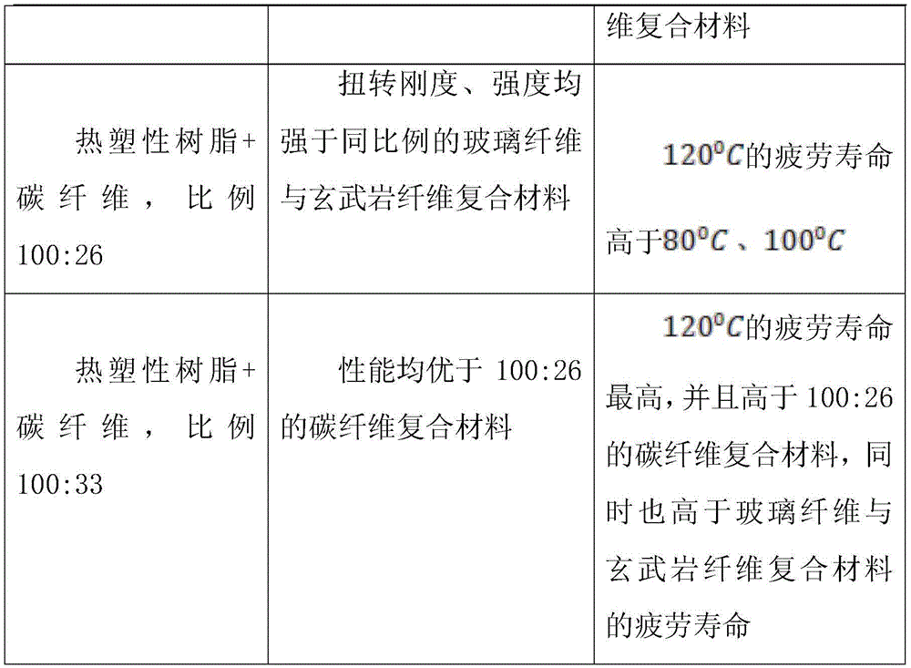
通过若干试验,以测试材料、铺设方式、固化温度之间的关系,见下表:Through several tests to test the relationship between materials, laying methods and curing temperature, see the table below:

上述仅为本发明的具体实施例,同时凡本发明中所涉及的如“上、下、左、 右、中间”等词,仅作参考用,并非绝对限定,凡利用本发明进行非实质性的 改动,均应属于侵犯本发明保护范围的行为。Above-mentioned is only the specific embodiment of the present invention, all the words such as " up, down, left, right, middle " involved in the present invention are only used for reference, are not absolutely limited, all utilize the present invention to carry out non-essential Any change should be an act of violating the protection scope of the present invention.
Claims (10)
Priority Applications (1)
| Application Number | Priority Date | Filing Date | Title |
|---|---|---|---|
| CN202210544725.1A CN115534353A (en) | 2022-05-19 | 2022-05-19 | Manufacturing process of composite material axle shell assembly for automobile chassis |
Applications Claiming Priority (1)
| Application Number | Priority Date | Filing Date | Title |
|---|---|---|---|
| CN202210544725.1A CN115534353A (en) | 2022-05-19 | 2022-05-19 | Manufacturing process of composite material axle shell assembly for automobile chassis |
Publications (1)
| Publication Number | Publication Date |
|---|---|
| CN115534353A true CN115534353A (en) | 2022-12-30 |
Family
ID=84723323
Family Applications (1)
| Application Number | Title | Priority Date | Filing Date |
|---|---|---|---|
| CN202210544725.1A Pending CN115534353A (en) | 2022-05-19 | 2022-05-19 | Manufacturing process of composite material axle shell assembly for automobile chassis |
Country Status (1)
| Country | Link |
|---|---|
| CN (1) | CN115534353A (en) |
Cited By (1)
| Publication number | Priority date | Publication date | Assignee | Title |
|---|---|---|---|---|
| CN119795615A (en) * | 2023-10-10 | 2025-04-11 | 汉达精密电子(昆山)有限公司 | A method for manufacturing a Bluetooth speaker housing using basalt fiber composite material and its product |
Citations (14)
| Publication number | Priority date | Publication date | Assignee | Title |
|---|---|---|---|---|
| CN1032425A (en) * | 1987-10-05 | 1989-04-19 | 托尔S·A公司 | Travelling device for vehicle of automobile type |
| US20040112942A1 (en) * | 2002-12-16 | 2004-06-17 | Durand Robert D. | Method for joining axle components |
| US20150204435A1 (en) * | 2014-01-22 | 2015-07-23 | Jtekt Corporation | Rack housing manufacturing method and rack housing |
| CN104985829A (en) * | 2015-04-03 | 2015-10-21 | 上海华渔新材料科技有限公司 | One-section type composite material vehicle transmission shaft preparation method |
| WO2015197279A1 (en) * | 2014-06-26 | 2015-12-30 | Zf Friedrichshafen Ag | Suspension arm made of fiber composite |
| CN106393731A (en) * | 2016-11-02 | 2017-02-15 | 上海复合材料科技有限公司 | Preparing method for composite material automobile connecting rod |
| CN108215244A (en) * | 2018-01-24 | 2018-06-29 | 株洲时代新材料科技股份有限公司 | The manufacturing method of axle box cover, product and design method under fiber hybrid composite |
| CN108506455A (en) * | 2017-02-27 | 2018-09-07 | 通用汽车环球科技运作有限责任公司 | Compound axle housing and its manufacturing method |
| CN109094057A (en) * | 2018-09-29 | 2018-12-28 | 中航复合材料有限责任公司 | A kind of carbon fiber automobile front chamber lid compression-moulding methods |
| FR3070190A1 (en) * | 2017-08-18 | 2019-02-22 | Psa Automobiles Sa | BALL JOINT OF A STEERING ROD OF A MOTOR VEHICLE |
| DE102017220962A1 (en) * | 2017-11-23 | 2019-05-23 | Zf Friedrichshafen Ag | Method for producing a Hinterachsgetriebequerträgers, Hinterachsgetriebequerträger and motor vehicle |
| CN112123815A (en) * | 2020-09-08 | 2020-12-25 | 华南农业大学 | Special-shaped hollow carbon tube body and its preparation process and special-shaped carbon fiber half shaft assembly |
| DE102020120172A1 (en) * | 2020-07-30 | 2022-02-03 | Bayerische Motoren Werke Aktiengesellschaft | Vehicle hatch and method for manufacturing a vehicle hatch |
| CN114425870A (en) * | 2020-10-12 | 2022-05-03 | 中国石油化工股份有限公司 | Motor train unit front end integrated vacuum infusion molding system and molding method |
-
2022
- 2022-05-19 CN CN202210544725.1A patent/CN115534353A/en active Pending
Patent Citations (14)
| Publication number | Priority date | Publication date | Assignee | Title |
|---|---|---|---|---|
| CN1032425A (en) * | 1987-10-05 | 1989-04-19 | 托尔S·A公司 | Travelling device for vehicle of automobile type |
| US20040112942A1 (en) * | 2002-12-16 | 2004-06-17 | Durand Robert D. | Method for joining axle components |
| US20150204435A1 (en) * | 2014-01-22 | 2015-07-23 | Jtekt Corporation | Rack housing manufacturing method and rack housing |
| WO2015197279A1 (en) * | 2014-06-26 | 2015-12-30 | Zf Friedrichshafen Ag | Suspension arm made of fiber composite |
| CN104985829A (en) * | 2015-04-03 | 2015-10-21 | 上海华渔新材料科技有限公司 | One-section type composite material vehicle transmission shaft preparation method |
| CN106393731A (en) * | 2016-11-02 | 2017-02-15 | 上海复合材料科技有限公司 | Preparing method for composite material automobile connecting rod |
| CN108506455A (en) * | 2017-02-27 | 2018-09-07 | 通用汽车环球科技运作有限责任公司 | Compound axle housing and its manufacturing method |
| FR3070190A1 (en) * | 2017-08-18 | 2019-02-22 | Psa Automobiles Sa | BALL JOINT OF A STEERING ROD OF A MOTOR VEHICLE |
| DE102017220962A1 (en) * | 2017-11-23 | 2019-05-23 | Zf Friedrichshafen Ag | Method for producing a Hinterachsgetriebequerträgers, Hinterachsgetriebequerträger and motor vehicle |
| CN108215244A (en) * | 2018-01-24 | 2018-06-29 | 株洲时代新材料科技股份有限公司 | The manufacturing method of axle box cover, product and design method under fiber hybrid composite |
| CN109094057A (en) * | 2018-09-29 | 2018-12-28 | 中航复合材料有限责任公司 | A kind of carbon fiber automobile front chamber lid compression-moulding methods |
| DE102020120172A1 (en) * | 2020-07-30 | 2022-02-03 | Bayerische Motoren Werke Aktiengesellschaft | Vehicle hatch and method for manufacturing a vehicle hatch |
| CN112123815A (en) * | 2020-09-08 | 2020-12-25 | 华南农业大学 | Special-shaped hollow carbon tube body and its preparation process and special-shaped carbon fiber half shaft assembly |
| CN114425870A (en) * | 2020-10-12 | 2022-05-03 | 中国石油化工股份有限公司 | Motor train unit front end integrated vacuum infusion molding system and molding method |
Cited By (1)
| Publication number | Priority date | Publication date | Assignee | Title |
|---|---|---|---|---|
| CN119795615A (en) * | 2023-10-10 | 2025-04-11 | 汉达精密电子(昆山)有限公司 | A method for manufacturing a Bluetooth speaker housing using basalt fiber composite material and its product |
Similar Documents
| Publication | Publication Date | Title |
|---|---|---|
| CN111331877B (en) | Preparation method of variable-stiffness composite material spiral spring | |
| KR20010075455A (en) | Hollow Structure of Fiber-Reinforced Resin and Method of Manufacturing The Same | |
| CN107521124A (en) | Carbon fiber dual platen reinforced structure part and its manufacture method | |
| CN102767471B (en) | Vertical axis wind power generator blade and manufacturing method thereof | |
| CN105666892B (en) | A kind of method that body of a motor car is manufactured with carbon fibre composite | |
| CN106738999A (en) | A kind of polyaxial carbon fibre composite car battery box and its manufacture method | |
| CN113021939B (en) | Manufacturing method of light-weight part based on continuous fibers and common fibers and product | |
| CN106626433A (en) | Automobile battery box made of multi-axial hybrid fiber composite material and manufacturing method of automobile battery box | |
| CN206287541U (en) | Carbon fibre composite helical spring and its mould | |
| CN115534353A (en) | Manufacturing process of composite material axle shell assembly for automobile chassis | |
| CN113291014B (en) | Preparation method of fiber reinforced composite material | |
| CN106626436A (en) | Hybrid fiber woven roving composite material automobile battery box and manufacturing method thereof | |
| JP4370917B2 (en) | Manufacturing method of fiber reinforced resin outer plate member | |
| CN112140582A (en) | Composite material transverse stabilizer bar preparation method and transverse stabilizer bar prepared by same | |
| EP3481654B1 (en) | A structural member | |
| JPH04254201A (en) | Resinous wheel | |
| CN108099317A (en) | A kind of high endurance composite material automobile leaf spring and preparation method thereof | |
| CN102514117B (en) | Carbon fiber enhanced polyphenylene sulfide composite material for automobile anticollision beam and method for manufacturing automobile anticollision beam | |
| CN111844947A (en) | Novel equipment cabin plate and preparation method thereof | |
| CN206999679U (en) | Carbon fiber dual platen reinforced structure part | |
| US12429024B2 (en) | Wind turbine blade shear web | |
| CN115648875A (en) | A kind of composite leaf spring and preparation method thereof | |
| CN205058640U (en) | Combined material integrated morphology | |
| CN105965918A (en) | Manufacturing process for automobile engine hood assembly of carbon fiber composite | |
| CN106240502A (en) | A kind of automobile-used energy absorbing member of composite and processing method thereof |
Legal Events
| Date | Code | Title | Description |
|---|---|---|---|
| PB01 | Publication | ||
| PB01 | Publication | ||
| SE01 | Entry into force of request for substantive examination | ||
| SE01 | Entry into force of request for substantive examination |