CN115518838B - Dispensing control method, device, equipment and storage medium - Google Patents
Dispensing control method, device, equipment and storage medium Download PDFInfo
- Publication number
- CN115518838B CN115518838B CN202211473167.0A CN202211473167A CN115518838B CN 115518838 B CN115518838 B CN 115518838B CN 202211473167 A CN202211473167 A CN 202211473167A CN 115518838 B CN115518838 B CN 115518838B
- Authority
- CN
- China
- Prior art keywords
- information
- preset
- dispensing
- target
- position information
- Prior art date
- Legal status (The legal status is an assumption and is not a legal conclusion. Google has not performed a legal analysis and makes no representation as to the accuracy of the status listed.)
- Active
Links
- 238000000034 method Methods 0.000 title claims abstract description 62
- 238000003860 storage Methods 0.000 title claims abstract description 19
- 239000003292 glue Substances 0.000 claims abstract description 82
- 230000033001 locomotion Effects 0.000 claims abstract description 36
- 230000006870 function Effects 0.000 description 26
- 230000008569 process Effects 0.000 description 9
- 238000010586 diagram Methods 0.000 description 7
- 238000004364 calculation method Methods 0.000 description 5
- 230000005540 biological transmission Effects 0.000 description 4
- 238000004891 communication Methods 0.000 description 4
- 230000008859 change Effects 0.000 description 3
- 230000003190 augmentative effect Effects 0.000 description 2
- 238000004590 computer program Methods 0.000 description 2
- 239000004973 liquid crystal related substance Substances 0.000 description 2
- 238000003062 neural network model Methods 0.000 description 2
- 230000003287 optical effect Effects 0.000 description 2
- 101100134058 Caenorhabditis elegans nth-1 gene Proteins 0.000 description 1
- 238000013473 artificial intelligence Methods 0.000 description 1
- 230000009286 beneficial effect Effects 0.000 description 1
- 238000007796 conventional method Methods 0.000 description 1
- 238000013500 data storage Methods 0.000 description 1
- 238000005516 engineering process Methods 0.000 description 1
- 238000009776 industrial production Methods 0.000 description 1
- 238000010295 mobile communication Methods 0.000 description 1
- 230000000750 progressive effect Effects 0.000 description 1
- 239000007787 solid Substances 0.000 description 1
Images


Classifications
-
- B—PERFORMING OPERATIONS; TRANSPORTING
- B05—SPRAYING OR ATOMISING IN GENERAL; APPLYING FLUENT MATERIALS TO SURFACES, IN GENERAL
- B05C—APPARATUS FOR APPLYING FLUENT MATERIALS TO SURFACES, IN GENERAL
- B05C5/00—Apparatus in which liquid or other fluent material is projected, poured or allowed to flow on to the surface of the work
- B05C5/02—Apparatus in which liquid or other fluent material is projected, poured or allowed to flow on to the surface of the work the liquid or other fluent material being discharged through an outlet orifice by pressure, e.g. from an outlet device in contact or almost in contact, with the work
- B05C5/0208—Apparatus in which liquid or other fluent material is projected, poured or allowed to flow on to the surface of the work the liquid or other fluent material being discharged through an outlet orifice by pressure, e.g. from an outlet device in contact or almost in contact, with the work for applying liquid or other fluent material to separate articles
-
- B—PERFORMING OPERATIONS; TRANSPORTING
- B05—SPRAYING OR ATOMISING IN GENERAL; APPLYING FLUENT MATERIALS TO SURFACES, IN GENERAL
- B05C—APPARATUS FOR APPLYING FLUENT MATERIALS TO SURFACES, IN GENERAL
- B05C11/00—Component parts, details or accessories not specifically provided for in groups B05C1/00 - B05C9/00
- B05C11/10—Storage, supply or control of liquid or other fluent material; Recovery of excess liquid or other fluent material
-
- Y—GENERAL TAGGING OF NEW TECHNOLOGICAL DEVELOPMENTS; GENERAL TAGGING OF CROSS-SECTIONAL TECHNOLOGIES SPANNING OVER SEVERAL SECTIONS OF THE IPC; TECHNICAL SUBJECTS COVERED BY FORMER USPC CROSS-REFERENCE ART COLLECTIONS [XRACs] AND DIGESTS
- Y02—TECHNOLOGIES OR APPLICATIONS FOR MITIGATION OR ADAPTATION AGAINST CLIMATE CHANGE
- Y02P—CLIMATE CHANGE MITIGATION TECHNOLOGIES IN THE PRODUCTION OR PROCESSING OF GOODS
- Y02P90/00—Enabling technologies with a potential contribution to greenhouse gas [GHG] emissions mitigation
- Y02P90/02—Total factory control, e.g. smart factories, flexible manufacturing systems [FMS] or integrated manufacturing systems [IMS]
Landscapes
- Coating Apparatus (AREA)
Abstract
The application discloses a dispensing control method, a device, equipment and a storage medium, wherein the method comprises the following steps: acquiring position offset information corresponding to a target object and initial point glue parameters of a motion reference shaft in glue dispensing equipment; the position offset information characterizes offset information of a target object relative to a reference object, wherein the reference object is an object to be dispensed, and the object can provide reference position information; adjusting the initial point glue parameter according to the position offset information to obtain a target point glue parameter; determining a dispensing path of the dispensing device based on the target dispensing parameters; the dispensing equipment is controlled to perform dispensing treatment on the target object based on the dispensing path; according to the method and the device, before dispensing is carried out on the target object, the initial point glue parameters of the motion reference shaft corresponding to the target object are adjusted through the position offset information of the target object, so that a more accurate glue dispensing path matched with the target object is determined, and the dispensing precision of the target object is improved.
Description
Technical Field
The present disclosure relates to the field of dispensing technologies, and in particular, to a dispensing control method, device, equipment, and storage medium.
Background
The dispensing machine is widely used in industry, and in industrial production, a plurality of products need to be subjected to dispensing treatment; such as integrated circuits, printed circuit boards, color liquid crystal displays, electronic components (e.g., relays, speakers), automotive parts, and the like.
When the conventional dispensing equipment is used for dispensing products, the problems of low working efficiency, long dispensing period, low dispensing precision and the like exist.
Disclosure of Invention
In order to solve the technical problems, the application discloses a dispensing control method, which adjusts initial point glue parameters of a motion reference shaft corresponding to a target object through position offset information of the target object before dispensing the target object, so as to determine a more accurate glue dispensing path matched with the target object and improve dispensing precision.
In order to achieve the above object, the present application provides a dispensing control method, which includes:
acquiring position offset information corresponding to a target object and initial point glue parameters of a motion reference shaft in glue dispensing equipment; the position offset information characterizes offset information of the target object relative to a reference object, wherein the reference object is an object to be dispensed, and the object can provide reference position information;
Adjusting the initial point glue parameter according to the position offset information to obtain a target point glue parameter;
determining a dispensing path of the dispensing device based on the target dispensing parameter;
and controlling the dispensing equipment to perform dispensing treatment on the target object based on the dispensing path.
In some embodiments, the method further comprises:
acquiring preset dispensing parameters of the motion reference shaft in the dispensing equipment, and preset coordinate information and actual coordinate information corresponding to a dispensing head in the dispensing equipment;
and under the condition that the preset coordinate information is inconsistent with the actual coordinate information, adjusting the preset dispensing parameter based on the preset coordinate information and the actual coordinate information to obtain the initial dispensing parameter.
In some embodiments, when the preset coordinate information is inconsistent with the actual coordinate information, adjusting the preset dispensing parameter based on the preset coordinate information and the actual coordinate information to obtain the initial dispensing parameter includes:
under the condition that the preset coordinate information and the actual coordinate information are inconsistent, determining coordinate deviation based on the preset coordinate information and the actual coordinate information;
And adjusting the initial point glue parameter according to the coordinate deviation to obtain the initial point glue parameter.
In some embodiments, the initial point glue parameters of the motion reference shaft comprise a rotation center of a preset rotation shaft, a preset balance position and a workpiece origin of a preset sliding shaft; the position offset information comprises an angle offset value and a distance offset value; the target point glue parameter comprises a target leveling position of the preset rotating shaft, a target rotating center and a target workpiece original point of the preset sliding shaft; the step of adjusting the initial point glue parameter according to the position offset information to obtain a target point glue parameter comprises the following steps:
adjusting the preset leveling position of the preset rotating shaft based on the angle deviation value to obtain a target leveling position of the preset rotating shaft;
adjusting the workpiece origin of the preset sliding shaft based on the distance offset value to obtain a target workpiece origin of the preset sliding shaft;
and determining the rotation center of the preset rotation axis as a target rotation center of the preset rotation axis.
In some embodiments, the motion reference axis comprises a first rotation axis, and the position offset information comprises an angle offset value and a distance offset value; the position offset information corresponding to the target object is acquired; comprising the following steps:
Acquiring the reference position information and the reference angle information of a reference object corresponding to the target object;
acquiring actual position information and actual angle information of the target object and a first rotation center of the first rotation shaft;
determining the angle deviation value of the target object relative to the reference object according to the actual angle information and the reference angle information;
and determining the distance offset value of the target object relative to the reference object according to the actual position information, the first rotation center, the angle offset value and the reference position information.
In some embodiments, the determining the distance offset value of the target object relative to the reference object based on the actual position information, the first rotation center, the angular deviation information, and the baseline position information includes:
determining target position information based on the actual position information, the first rotation center, and the angle deviation value;
and determining a difference between the target position information and the reference position information as the distance offset value of the target object relative to the reference object.
In some embodiments, the obtaining the reference position information and the reference angle information of the reference object corresponding to the target object includes:
acquiring first position information and at least one second position information of a reference object corresponding to a target object, wherein the first position information is the position information of a first auxiliary reference point on the reference object;
determining the first position information as base position information of the reference object;
determining base angle information of the reference object based on the first position information and the second position information.
The application also provides a dispensing control device, the device include:
the data acquisition module is used for acquiring position offset information corresponding to the target object and initial point glue parameters of a motion reference shaft in the glue dispensing equipment; the position offset information characterizes offset information of the target object relative to a reference object, wherein the reference object is an object to be dispensed, and the object can provide reference position information;
the first adjusting module is used for adjusting the initial point glue parameter according to the position offset information to obtain a target point glue parameter;
The path determining module is used for determining a dispensing path of the dispensing device based on the target point glue parameter;
and the dispensing control module is used for controlling the dispensing equipment to perform dispensing treatment on the target object based on the dispensing path.
The application also provides a dispensing control device, which comprises a processor and a memory, wherein at least one instruction or at least one section of program is stored in the memory, and the at least one instruction or the at least one section of program is loaded and executed by the processor to realize the dispensing control method.
The application also provides a computer readable storage medium, wherein at least one instruction or at least one section of program is stored in the storage medium, and the at least one instruction or the at least one section of program is loaded by a processor and executes the dispensing control method.
The implementation of the embodiment of the application has the following beneficial effects:
according to the dispensing control method, before dispensing is carried out on the target object, the initial point glue parameters of the motion reference shaft corresponding to the target object are adjusted according to the position offset information of the target object, so that a more accurate spot glue path matched with the target object is determined, and the dispensing precision of the target object is improved.
Drawings
In order to more clearly describe the dispensing control method, device, apparatus and storage medium described herein, the drawings required for the embodiments will be briefly described below, and it will be apparent that the drawings in the following description are only some embodiments of the present application, and other drawings may be obtained according to these drawings without inventive effort for those skilled in the art.
Fig. 1 is a schematic diagram of an implementation environment of a dispensing control method according to an embodiment of the present application;
fig. 2 is a schematic structural diagram of a dispensing device according to an embodiment of the present application;
fig. 3 is a schematic flow chart of a dispensing control method according to an embodiment of the present application;
fig. 4 is a flowchart of a method for obtaining position offset information according to an embodiment of the present application;
fig. 5 is a flowchart of a method for determining a target glue parameter according to an embodiment of the present application;
fig. 6 is a flow chart of another dispensing control method according to an embodiment of the present disclosure;
fig. 7 is a schematic structural diagram of a dispensing control device according to an embodiment of the present application;
fig. 8 is a schematic structural diagram of an electronic device according to an embodiment of the present application.
Detailed Description
The following description of the embodiments of the present application will be made clearly and fully with reference to the accompanying drawings, in which it is evident that the embodiments described are only some, but not all, of the embodiments of the present application. All other embodiments, which can be made by one of ordinary skill in the art without undue burden from the present disclosure, are within the scope of the present application based on the embodiments herein.
It should be noted that the terms "first," "second," and the like in the description and claims of the present application and the above figures are used for distinguishing between similar objects and not necessarily for describing a particular sequential or chronological order. It is to be understood that the data so used may be interchanged where appropriate such that embodiments of the present application described herein may be implemented in sequences other than those illustrated or otherwise described herein. Furthermore, the terms "comprises," "comprising," and "having," and any variations thereof, are intended to cover a non-exclusive inclusion, such that a process, method, system, article, or server that comprises a list of steps or elements is not necessarily limited to those steps or elements expressly listed or inherent to such process, method, article, or apparatus, but may include other steps or elements not expressly listed or inherent to such process, method, article, or apparatus.
Referring to fig. 1, a schematic diagram of an implementation environment provided in an embodiment of the present application is shown, where the implementation environment may include:
at least one terminal 01 and at least one server 02. The at least one terminal 01 and the at least one server 02 may communicate data over a network.
In an alternative embodiment, the terminal 01 may be an executor of the dispensing control method. The terminal 01 may include, but is not limited to, a vehicle-mounted terminal, a smart phone, a desktop computer, a tablet computer, a notebook computer, a smart speaker, a digital assistant, an augmented reality (augmented reality, AR)/Virtual Reality (VR) device, a smart wearable device, and the like. The operating system running on terminal 01 may include, but is not limited to, an android system, an IOS system, linux, windows, unix, and the like.
The server 02 can provide the terminal 01 with position offset information corresponding to the target object and initial glue parameters of a motion reference axis in the glue dispensing device. Optionally, the server 02 may be an independent physical server, or may be a server cluster or a distributed system formed by a plurality of physical servers, or may be a cloud server that provides cloud services, cloud databases, cloud computing, cloud functions, cloud storage, network services, cloud communication, middleware services, domain name services, security services, CDNs (Content Delivery Network, content delivery networks), and basic cloud computing services such as big data and artificial intelligence platforms.
Please refer to fig. 2, which is a schematic structural diagram of a dispensing apparatus according to an embodiment of the present application; the dispensing device can be five-axis dispensing device, and the five-axis dispensing device can comprise a dispensing head 1, an image acquisition device 2, a first rotating shaft 3, a second rotating shaft 4, a first sliding shaft 5, a second sliding shaft 6 and a third sliding shaft 7; wherein the first sliding shaft 5, the second sliding shaft 6 and the third sliding shaft 7 may form a three-dimensional space, for example, the first sliding shaft 5 may be an x-axis; the second sliding axis 6 may be a y-axis and the third sliding axis 7 may be a z-axis.
In some exemplary embodiments, the image capturing device 2 and the dispensing head 1 are both slidable with respect to the first sliding shaft 5, the second sliding shaft 6 and the third sliding shaft 7; so that the image pickup device 2 and the dispensing head 1 can move in space. Wherein the image acquisition device 2 may be a CCD (charge coupled device ) camera; the image acquisition device 2 is used for acquiring images of the target object 8 on the first rotation axis 3. The dispensing head 1 may be a dispensing needle.
In some exemplary embodiments, the first rotation shaft 3 and the second rotation shaft 4 may be used to rotate the target object; one end of the first rotating shaft 3 is fixedly connected with the second rotating shaft 4, and the other end of the first rotating shaft is used for accommodating a target object; the first rotation shaft 3 can be rotated independently of the second rotation shaft 4. The target object may be a product to be dispensed; the central axis of the first rotating shaft 3 may be parallel to the central axis of the third sliding shaft 7; the first rotating shaft 3 can rotate around the central axis, and the target object on the first rotating shaft 3 synchronously rotates; the central axis of the second rotating shaft 4 can be parallel to the second sliding shaft 6, and the second rotating shaft 4 can rotate around the central axis thereof, so as to drive the first rotating shaft 3 and the target object on the first rotating shaft 3 to synchronously rotate.
In some exemplary embodiments, the device further comprises a control device for controlling the driving device to output a driving force, and a driving device for driving the image capturing device or the dispensing head to slide relative to the first sliding shaft 5, the second sliding shaft 6 and the third sliding shaft 7. The driving device is also used for driving the first rotating shaft 3 and the second rotating shaft 4 to rotate. The control device is respectively in communication connection with the image acquisition device 2 and the dispensing head 1.
In one example, before dispensing the target object 8, the driving device may drive the image capturing device to slide along the first sliding shaft 5, the second sliding shaft 6 and the third sliding shaft 6, so that the image capturing device 2 moves to a preset position, and the control device controls the image capturing device to capture an image of the target object;
in the process of dispensing the target object, the driving device can be used for driving one or more of sliding movements of the dispensing head of the dispensing point 1 along the first sliding shaft 5, the second sliding shaft 6 and the third sliding shaft 7; it is also possible to synchronously drive one or more of the first rotation shaft 3 and the second rotation shaft 4 to rotate; to achieve multi-angle dispensing of the target object 8.
In this embodiment, the five-axis dispensing equipment that this application provided can carry out three-dimensional multi-angle point to the target object and glue, and the point glues efficiently, effectual, can adapt to the shape of target object.
Referring to fig. 3, which is a flowchart illustrating a method for controlling dispensing according to an embodiment of the present application, the present disclosure provides steps of a method according to an embodiment or a flowchart, but is based on a conventional method; or the non-inventive labor may include more or fewer operational steps. The step sequence listed in the embodiments is only one way of a plurality of step execution sequences, does not represent a unique execution sequence, and the dispensing control method can be executed sequentially according to the methods shown in the embodiments or the drawings. As shown in fig. 3, the method includes:
s301, acquiring position offset information corresponding to a target object and initial point glue parameters of a motion reference shaft in glue dispensing equipment.
In the embodiment of the present application, the target object may be an object to be dispensed placed on the dispensing device; for example, the target object may be an integrated circuit, a printed circuit board, an electronic component, or the like. The positional offset information may characterize offset information of the target object relative to the reference object; for example, the positional offset information may include an angular offset value and a distance offset value. The reference object may be an object capable of providing reference position information for the target object; the reference object may be a previous object adjacent to the target object glue order.
In one exemplary embodiment, the target objects may include a first target object, a second target object, a..the nth target object; the dispensing sequence corresponding to the first target object may be 1, the dispensing sequence corresponding to the second target object may be 2, and the dispensing sequence corresponding to the nth target object may be N; the reference object corresponding to the nth target object may be an nth-1 target object; the reference object corresponding to the first target object may be a 0 th target object, and the 0 th target object may refer to a preset calibration object before the first dispensing is performed;
in one example, after the position parameter is calibrated by using the preset calibration object, the preset calibration object may be used as a first target object to perform dispensing processing, where the reference object is the first target object itself.
In the embodiment of the present application, the dispensing device may be a multi-axis dispensing device for dispensing a target object; for example, the dispensing device may be a five-axis dispensing device. The motion reference shaft can be a shaft which can drive a device for dispensing and for assisting in dispensing and a target object in the dispensing equipment to move. The device for dispensing may be a dispensing head, and the device for assisting dispensing may include an image acquisition device. For example, the movement reference axis may include a preset sliding axis capable of driving the device for dispensing and for assisting in dispensing to move and a preset movement axis capable of driving the target object to rotate. The preset sliding shaft may include a first sliding shaft, a second sliding shaft, and a third sliding shaft. The preset rotation shaft may include a first rotation shaft and a second rotation shaft. The initial glue parameter of the motion reference axis may refer to an initial glue parameter corresponding to the target object. The initial glue parameter may refer to a motion parameter of a motion reference axis in a mechanical coordinate system during a glue dispensing process. The initial glue dispensing parameter may be a preset glue dispensing parameter, or may be a parameter after the preset glue dispensing parameter is adjusted. For example, the initial point glue parameters may include a workpiece origin of a preset sliding axis under a mechanical coordinate system and a rotation center and a preset leveling position of a preset rotating axis under the mechanical coordinate system; the preset leveling position may be a position of a preset rotating shaft when the preset object to be dispensed is in a preset horizontal placement state.
In some exemplary embodiments, target pose information of a target object and reference pose information of a reference object are acquired; and carrying out position offset calculation according to the target pose information and the reference pose information to obtain position offset information. The target pose information can represent target position information and target direction information of a target object; the reference pose information may characterize reference position information and reference direction information of the reference object.
In one example, image information of a target object may be acquired based on an image acquisition device; analyzing and processing the image information of the target object to obtain target position information of the target object;
the distance offset value can be calculated according to the target position information and the reference position information; and determining an angle deviation value according to the target direction information and the reference direction information.
In other exemplary embodiments, before acquiring the position offset information corresponding to the target object and the initial glue parameter of the motion reference axis in the glue dispensing apparatus, the method further includes: acquiring preset dispensing parameters of the motion reference shaft in the dispensing equipment, and preset coordinate information and actual coordinate information corresponding to a dispensing head in the dispensing equipment; and under the condition that the preset coordinate information is consistent with the actual coordinate information, determining the preset dispensing parameter as an initial point dispensing parameter. The preset dispensing parameters may refer to dispensing parameters of each axis in the preset motion reference axis. For example, the preset dispensing parameters may include a preset rotation center and a preset leveling position of the preset rotation shaft; and presetting the original point of the workpiece of the preset sliding shaft.
S303, adjusting the initial point glue parameter according to the position offset information to obtain the target point glue parameter.
In the embodiment of the application, the initial point glue parameters of the motion reference shaft comprise a rotation center of a preset rotation shaft, a preset swing position and a workpiece origin of a preset sliding shaft; the position offset information includes an angle offset value and a distance offset value; the target point glue parameter comprises a target leveling position of a preset rotating shaft, a target rotating center and a target workpiece origin of a preset sliding shaft;
in the embodiment of the present application, the target glue parameter may be partially different from or completely the same as the initial glue parameter.
In some exemplary embodiments, preset compensation configuration information may be acquired; and adjusting the initial point glue parameter based on preset compensation configuration information and position offset information to obtain the target point glue parameter.
In one example, the compensation coefficients of the rotation center, the preset balance position, and the angle offset value and the distance offset value corresponding to the origin of the workpiece may be obtained based on preset compensation configuration information. The compensation coefficient comprises a first compensation coefficient of an angle deviation value and a distance deviation value corresponding to the rotation center, a second compensation coefficient of an angle deviation value and a distance deviation value corresponding to the preset balance position, and a third compensation coefficient of an angle deviation value and a distance deviation value corresponding to the origin of the workpiece.
Correspondingly, adjusting the rotation center based on the first compensation coefficient, the angle deviation value and the distance deviation value to obtain a target rotation center;
adjusting the preset leveling position based on the second compensation coefficient, the angle deviation value and the distance deviation value to obtain a target leveling position;
and adjusting the origin of the workpiece based on the third compensation coefficient, the angle offset value and the distance offset value to obtain a target origin of the workpiece.
S305, determining a dispensing path of the dispensing device based on the dispensing parameter of the target point;
in the embodiment of the application, the dispensing path can be a movement path of the pointing device, in which the rotating shaft and the sliding shaft are preset in the process of dispensing the target object, under the coordinate system of the workpiece.
In some exemplary embodiments, preset path configuration information may be acquired; and calculating based on the preset path configuration information, the target leveling position of the preset rotating shaft in the target point glue parameters, the target rotating center and the target workpiece origin of the preset sliding shaft to obtain a glue dispensing path. The preset path configuration information can represent the association relation and relation coefficient between the data in the target point glue parameters.
In other exemplary embodiments, a preset neural network model may be obtained, and the target point glue data is processed based on the preset neural network model to obtain a glue dispensing path.
S307, the control dispensing device performs dispensing processing on the target object based on the dispensing path.
In the embodiment of the application, the motion reference shaft in the dispensing equipment can be controlled to move according to the dispensing path, so that the dispensing treatment of the target object is realized.
In some exemplary embodiments, dispensing may be controlled based on a control card; specifically, the pulse output signal of the control card can be used as the trigger signal of the dispensing head in the process of dispensing the target object, the space equidistant pulse output function of the control card is used, the space equidistant dispensing function is realized, and the glue piling problem in the process of dispensing is avoided.
In this embodiment, before dispensing the target object, the initial glue point parameter of the motion reference axis corresponding to the target object is adjusted according to the position offset information of the target object, so that a more accurate glue point path matched with the target object is determined, and the glue dispensing precision is improved.
In an exemplary embodiment, as shown in fig. 4, a flowchart of a method for acquiring position offset information according to an embodiment of the present application is shown; specifically, the following is described.
S401, acquiring the reference position information and the reference angle information of a reference object corresponding to a target object;
In the embodiment of the present application, the reference position information may be position information of a first reference point on the reference object; the base angle information may characterize angle information between a first reference point and a first auxiliary reference point on the reference object; wherein the first reference point and the first auxiliary reference point are respectively located on different sides of the reference object. The selection mode of the reference point can be preset; the selection mode of the auxiliary reference point can also be preset.
In some exemplary embodiments, first position information of a reference object corresponding to a target object and at least one second position information are acquired, the first position information being position information of a first auxiliary reference point on the reference object; determining the first position information as the base position information of the reference object; the base angle information of the reference object is determined based on the first position information and the second position information.
In one example, the image acquisition device may be controlled to move to a first preset position to acquire first image information of a first base reference point; controlling the image acquisition device to move to a second preset position, and acquiring second image information of the first auxiliary reference point; analyzing and processing the first image information to obtain first position information; and analyzing and processing the second image information to obtain second position information. The first preset position may be a preset position where the first reference point information can be acquired; the second preset position may be a preset position where the first auxiliary reference point information can be acquired.
Correspondingly, an angle between the first position information and the second position information is determined as the base angle information of the reference object.
In one example, the calculation of the reference angle information may be performed using a function model one, specifically as follows:
function model one:

wherein a1 represents an angle corresponding to the reference angle information; (Xm 1, ym 1) represents the position of the first base reference point in the mechanical coordinate system; (Xm 2, ym 2) represents the position of the first auxiliary reference point in the mechanical coordinate system.
S403, acquiring actual position information and actual angle information of a target object and a first rotation center of a first rotation shaft;
in the embodiment of the present application, the actual position information may be position information of a second reference point on the target object; the actual angle information may characterize angle information between a second reference point and a second auxiliary reference point on the target object; wherein the second reference point and the second auxiliary reference point are respectively located on different sides of the target object. The selection mode of the reference point can be preset; the selection mode of the auxiliary reference point can also be preset.
In some exemplary embodiments, third position information of the target object is acquired, the third position information being position information of a second base reference point on the target object, and at least one fourth position information being position information of a second auxiliary reference point on the target object; determining the third position information as actual position information of the target object; actual angle information of the target object is determined based on the third position information and the fourth position information.
In one example, the image acquisition device may be controlled to move to a third preset position to acquire third image information of the second fiducial reference point; controlling the image acquisition device to move to a fourth preset position to acquire fourth image information of a second auxiliary reference point; analyzing and processing the third image information to obtain third position information; and analyzing and processing the fourth image information to obtain fourth position information. The third preset position may be a preset position where the second reference point information can be acquired; the fourth preset position may be a preset position where the second auxiliary reference point information can be acquired.
Correspondingly, the angle between the third position information and the fourth position information is determined as the actual angle information of the target object.
In one example, the calculation of the actual angle information may be performed using a second functional model, as follows:
and a function model II:

wherein a2 represents an angle corresponding to the actual angle information; (Xm 3, ym 3) represents the position of the second base reference point in the mechanical coordinate system; (Xm 4, ym 4) represents the position of the second auxiliary reference point in the mechanical coordinate system.
And S405, determining the angle deviation value of the target object relative to the reference object according to the actual angle information and the base angle information.
In the embodiment of the application, the difference between the angle corresponding to the actual angle information and the angle corresponding to the reference angle information may be determined as the angle deviation value;
in one example, the calculation of the angular deviation value may be performed using a function model three, as follows:
and (3) a function model III:
wherein a represents an angle deviation value, and a2 represents an angle corresponding to actual angle information; a1 represents an angle corresponding to the reference angle information.
S407, determining a distance offset value of the target object relative to the reference object according to the actual position information, the first rotation center, the angle offset value and the reference position information.
In some exemplary embodiments, the target location information may be determined based on the actual location information, the first center of rotation, and the angular offset value; the difference between the target position information and the reference position information is determined as a distance offset value of the target object with respect to the reference object.
In one example, a radius of rotation and an initial angle relative to a first center of rotation corresponding to a target object may be determined from actual location information and the first center of rotation; determining the sum of the initial angle and the angle deviation value as a target angle of the target object; the target position information is determined based on the target angle, the radius of rotation, and the first center of rotation. The target angle may be an angle with respect to the first rotation center after the target object rotates around the first rotation center by an angle corresponding to the angle deviation value.
Specifically, the initial angle may be an angle of the second base reference point with respect to the first rotation center; the target angle may be an angle of the second base reference point with respect to the first rotation center after rotating around the first rotation center by an angle corresponding to the angle deviation value.
In one example, the calculation of the target location information may be performed using functional models four through eight, as follows:
and a function model IV:

and fifthly, a function model:

and (3) a function model six:

function model seven:

function model eight:

wherein R represents a rotation radius; (Xm 3, ym 3) represents the position of the actual position information corresponding to the second base reference point in the machine coordinate system; (Xc, yc) represents the position of the first rotation center in the mechanical coordinate system; b represents an initial angle; a represents an angle deviation value; b' represents a target angle; (Xm 3', ym 3') represents the position of the target position information corresponding to the second base reference point in the machine coordinate system.
In one example, the difference between the target position information and the reference position information may be (Xm 3', ym 3') and (Xm 1, ym 1); i.e. the distance offset value is equal to (Xm 3'-Xm1, ym3' -Ym 1).
In this embodiment, the present application calculates the position offset information by the reference position information and the reference angle information of the reference object corresponding to the target object and the actual position information and the actual angle information corresponding to the target object, so that the accurate offset information can be obtained.
In some exemplary embodiments, fig. 5 is a flowchart illustrating a method for determining a target glue parameter according to an embodiment of the present application; specifically, the following is described.
S501, adjusting the preset leveling position of the preset rotating shaft based on the angle deviation value to obtain a target leveling position of the preset rotating shaft;
in the embodiment of the present application, the preset leveling position may include a first preset leveling position of the first rotation axis and a second preset leveling position of the second rotation axis; the target leveling positions may include a first target leveling position of the first axis of rotation and a second target leveling position of the second axis of rotation.
In some exemplary embodiments, a weighting coefficient corresponding to the angle deviation value may be obtained; multiplying the angle deviation value by the weighting coefficient to obtain a target deviation value; and determining the sum of the target deviation value and the preset leveling position as the target leveling position.
Specifically, the weighting coefficients corresponding to the first rotation axis and the second rotation axis are different.
In one example, a first weighting coefficient corresponding to a first rotation axis may be obtained; and adding the product of the angle deviation value and the first weighting coefficient to a value corresponding to the first preset leveling position to obtain a first target leveling position. Wherein the first weighting coefficient may be 1.
For example, a function model nine may be used to calculate a first target roll-off position for a first axis of rotation:
and (3) a function model nine:

wherein C is 0 Representing a first preset balance position; a represents an angle deviation value; d1 represents a first weighting coefficient, wherein d1 is equal to 1; f1 represents the first target leveling position.
In another example, a second weighting coefficient corresponding to a second rotation axis may be obtained; and adding the product of the angle deviation value and the second weighting coefficient to a value corresponding to a second preset leveling position to obtain a second target leveling position. Wherein the second weighting factor may be 0. That is, the angle deviation value is not adjusted to the preset leveling position of the second rotation shaft.
For example, the functional model ten may be used to calculate the second target roll position for the first axis of rotation:
function model ten:

wherein A is 0 Representing a second preset balance position; a represents an angle deviation value; d2 represents a second weighting factor, wherein d2 is equal to 0; f2 represents the first target leveling position.
S503, adjusting the workpiece origin of the preset sliding shaft based on the distance offset value to obtain a target workpiece origin of the preset sliding shaft;
in the embodiment of the application, the workpiece origin may include a first workpiece origin of the first sliding shaft, a second workpiece origin of the second sliding shaft, and a third workpiece origin of the third sliding shaft; the target workpiece origins may include a first target workpiece origin of the first sliding axis, a second target workpiece origin of the second sliding axis, and a third target workpiece origin of the third sliding axis. For example, the first sliding axis may be the x-axis; the second sliding axis may be the y-axis and the third sliding axis may be the z-axis.
In some exemplary embodiments, the workpiece origins of the sliding axes in the same dimension may be adjusted according to the coordinate dimensions of the mechanical coordinate system corresponding to the distance offset value, respectively.
The distance offset value of the target object is a two-dimensional coordinate difference value; for example (Xm 3'-Xm1, ym3' -Ym 1)
In one example, in a case where the first sliding axis is the x axis, a sum of a value corresponding to the first workpiece origin of the first sliding axis and the distance offset value may be determined as the first target workpiece origin.
When the second sliding axis is the y axis, the sum of the distance offset value and the value corresponding to the second workpiece origin of the second sliding axis may be determined as the second target workpiece origin.
In the case where the third sliding axis is the z axis, the distance offset value may not be compensated in this dimension, that is, the third workpiece origin of the third sliding axis may be determined as the third target workpiece origin.
For example, eleven to twelve functional models may be employed to calculate a first target workpiece origin for a first axis of rotation and a second target workpiece origin for a second axis of rotation:
function model eleven:

twelve function models:

s1 represents a first target workpiece origin; x is X 0 Representing a first preset workpiece origin; y is Y 0 Representing a second preset workpiece origin, wherein Xm3' -Xm1 represents a distance offset value on an x-axis; s2 represents a second target workpiece origin; (Ym 3' -Ym 1) represents a distance offset value on the y-axis. Wherein in this example, the first preset workpiece origin is the first workpiece origin, the second preset workpiece origin and the second workpiece origin.
S505, the rotation center of the preset rotation axis is determined as the target rotation center of the preset rotation axis.
In the embodiment of the present application, the positional offset information of the target object may not be adjusted for the rotation center of the preset rotation axis; or when the positional deviation information of the target object adjusts the rotation center of the preset rotation axis, the adjustment coefficient thereof may be 0.
In one example, the first rotation center of the first rotation shaft may be a first preset rotation center (Xc, yc); the second rotation center of the second rotation shaft may be a second preset rotation center (Xa, za).
In the embodiment, the distance offset value and the angle offset value of the position offset information are adopted to respectively adjust the workpiece origin of the preset sliding shaft, the rotation center of the preset rotating shaft and the preset balance position, so that more accurate dispensing parameters which are more suitable for target objects can be obtained; and further, the dispensing precision of the target object can be further improved.
In some exemplary embodiments, fig. 6 is a schematic flow chart of another dispensing control method according to an embodiment of the present application; specifically, the following is described.
S601, acquiring preset dispensing parameters of a motion reference shaft in dispensing equipment, preset coordinate information and actual coordinate information corresponding to a dispensing head in the dispensing equipment;
in this embodiment of the present application, the preset dispensing parameters may refer to dispensing parameters of each axis in the preset motion reference axis. The preset dispensing parameters can comprise a preset rotation center and a preset balance position of a preset rotating shaft and a preset workpiece origin of a preset sliding shaft. For example, the preset workpiece origins of the preset slide shafts may include a first preset workpiece origin of the first slide shaft, a second preset workpiece origin of the second slide shaft, and a third preset workpiece origin of the third slide shaft. The preset rotation centers of the preset rotation shafts may include a first preset rotation center of the first rotation shaft and a second preset rotation center of the second rotation shaft. The preset coordinate information may refer to coordinate information of the preset dispensing head under a mechanical coordinate system, may be three-dimensional coordinate information, for example, (Xn 0 ,Yn 0 ,Zn 0 )。
And S603, under the condition that the preset coordinate information is inconsistent with the actual coordinate information, adjusting the preset dispensing parameters based on the preset coordinate information and the actual coordinate information to obtain initial dispensing parameters.
In this embodiment of the present application, the initial-point glue parameter may include a rotation center of a preset rotation axis, a preset leveling position, and a workpiece origin of a preset sliding axis.
In some exemplary embodiments, in the case that the preset coordinate information is inconsistent with the actual coordinate information, the coordinate deviation may be determined based on the preset coordinate information and the actual coordinate information; and (3) adjusting the preset dispensing parameter based on the coordinate deviation to obtain the initial dispensing parameter.
In one example, the preset workpiece origin and the preset rotation center may be adjusted according to the coordinate deviation to obtain the workpiece origin; the preset rotation center can be adjusted according to the coordinate deviation, and the rotation center is obtained.
Specifically, the first preset workpiece origin, the second preset workpiece origin and the third preset workpiece origin can be respectively adjusted according to the dimensions corresponding to the coordinate deviation to obtain a first adjusted workpiece origin, a second adjusted workpiece origin and a third adjusted workpiece origin; determining a first adjusted workpiece origin as a first workpiece origin of the first sliding shaft; determining a second adjusted workpiece origin as a second workpiece origin of a second sliding shaft; and determining a third adjusted workpiece origin as a third workpiece origin of a third sliding axis.
The first preset rotation center and the second preset rotation center can be respectively adjusted according to the dimension corresponding to the coordinate deviation, so that the first adjustment rotation center and the second adjustment rotation center are obtained; determining a first adjustment rotation center as a first rotation center of the first rotation shaft; the second adjustment rotation center is determined as a second rotation center of the second rotation shaft.
For example, thirteen to fifteen functional models may be used to calculate the origin of the workpiece:
thirteen function models:

function model fourteen:

fifteen functional models:

wherein S3 represents the origin of the first adjustment workpiece; x is X 0 Representing a first preset workpiece origin; s4, a second adjusting workpiece origin; y is Y 0 S5 represents a third adjustment workpiece origin; z is Z 0 Representing a third preset workpiece origin; (Xn) 0 ,Yn 0 ,Zn 0 ) Representing preset coordinate information; (Xn) 1 ,Yn 1 ,Zn 1 ) Representing actual coordinate information; (Xn) 1 -Xn 0 ) Representing the coordinate deviation in the X-axis direction; (Yn) 1 -Yn 0 ) Representing the coordinate deviation in the Y-axis direction; (Zn) 1 -Zn 0 ) Indicating the coordinate deviation in the Z-axis direction.
The rotation center can also be calculated by using sixteen and seventeen function models:
sixteen functional models:

seventeen function models:

wherein L1 represents a first adjustment rotation center; l2 represents a second adjustment rotation center; (Xc, yc) represents a first preset rotation center; (Xa, za) represents a second preset rotation center; (Xn) 1 -Xn 0 ) Representing the coordinate deviation in the X-axis direction; (Yn) 1 -Yn 0 ) Representing the coordinate deviation in the Y-axis direction; (Zn) 1 -Zn 0 ) Indicating the coordinate deviation in the Z-axis direction.
In other exemplary embodiments, in the case that the preset coordinate information is inconsistent with the actual coordinate information, the coordinate angle deviation may be determined based on the preset coordinate information and the actual coordinate information; and (3) adjusting the preset dispensing parameter based on the coordinate angle deviation to obtain an initial dispensing parameter.
S605, position offset information corresponding to the target object is acquired.
S607, adjusting the initial point glue parameter according to the position offset information to obtain the target point glue parameter.
In the embodiment of the present application, the initial glue parameter is changed, and at this time, a part of parameters of the target glue parameter obtained after adjustment are also changed.
In one example, the positional deviation information may not readjust the rotation center of the preset rotation shaft; the preset leveling position may be adjusted by using the angle deviation value in the positional deviation information, and the change result thereof is the result of the solution in the function models 9 and 10 described above.
The position offset information is used for adjusting the workpiece origin of the preset sliding shaft to obtain a target workpiece origin of the preset sliding shaft, and the target workpiece origin can be changed according to the change of the distance offset value in the position offset information. The specific steps are as follows:
For example, eighteen to nineteen functional models may be employed to calculate a first target workpiece origin for a first axis of rotation and a second target workpiece origin for a second axis of rotation:
eighteen function models:

nineteen function models:
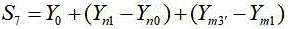
s6 represents a first target workpiece origin; x is X 0 +(Xn 1 -Xn 0 ) Representing a first workpiece origin; y is Y 0 Representing a second preset workpiece origin, wherein Xm3' -Xm 1 represents a distance offset value on an x-axis; s7, representing a second target workpiece origin; y is Y 0 +(Yn 1 -Yn 0 ) Representing a second workpiece origin; (Ym 3' -Ym 1) represents a distance offset value on the y-axis.
S609, determining a dispensing path of the dispensing device based on the dispensing parameter of the target point;
s611, controlling the dispensing device to perform dispensing processing on the target object based on the dispensing path.
In this embodiment, after the position of the dispensing head changes, the preset dispensing parameter is further adjusted through the coordinate deviation of the dispensing head, so that an error caused by the position change of the dispensing head can be avoided.
The embodiment of the application also provides a dispensing control device, as shown in fig. 7, which is a schematic structural diagram of the dispensing control device provided in the embodiment of the application; specifically, the device comprises:
the data acquisition module 701 is configured to acquire position offset information corresponding to a target object and an initial point glue parameter of a motion reference axis in the glue dispensing device; the position offset information characterizes offset information of the target object relative to a reference object, wherein the reference object is an object to be dispensed, and the object can provide reference position information;
the first adjusting module 702 is configured to adjust the initial glue parameter according to the position offset information to obtain a target glue parameter;
a path determining module 703, configured to determine a dispensing path of the dispensing device based on the target dispensing parameter;
and the dispensing control module 704 is configured to control the dispensing device to perform dispensing processing on the target object based on the dispensing path.
In an embodiment of the present application, further includes:
the information acquisition module is used for acquiring preset dispensing parameters of the motion reference shaft in the dispensing equipment, and preset coordinate information and actual coordinate information corresponding to a dispensing head in the dispensing equipment;
And the second adjusting module is used for adjusting the preset dispensing parameter based on the preset coordinate information and the actual coordinate information to obtain the initial dispensing parameter under the condition that the preset coordinate information is inconsistent with the actual coordinate information.
In an embodiment of the present application, the second adjustment module includes:
a first determining unit configured to determine a coordinate deviation based on the preset coordinate information and the actual coordinate information, in a case where the preset coordinate information and the actual coordinate information are inconsistent;
and the first adjusting unit is used for adjusting the initial point glue parameter according to the coordinate deviation to obtain the initial point glue parameter.
In this embodiment of the present application, the first adjustment module 702 includes:
the second adjusting unit is used for adjusting the preset leveling position of the preset rotating shaft based on the angle deviation value to obtain a target leveling position of the preset rotating shaft;
the third adjusting unit is used for adjusting the workpiece origin of the preset sliding shaft based on the distance offset value to obtain a target workpiece origin of the preset sliding shaft;
a second determining unit configured to determine a rotation center of the preset rotation axis as a target rotation center of the preset rotation axis.
In the embodiment of the present application, the data acquisition module 701 includes:
the first acquisition unit is used for acquiring the reference position information and the reference angle information of the reference object corresponding to the target object;
a second acquisition unit configured to acquire actual position information and actual angle information of the target object and a first rotation center of the first rotation axis;
a third determining unit configured to determine the angle deviation value of the target object with respect to the reference object according to the actual angle information and the reference angle information;
and a fourth determining unit configured to determine the distance offset value of the target object with respect to the reference object based on the actual position information, the first rotation center, the angle offset value, and the reference position information.
In an embodiment of the present application, the fourth determining unit includes:
a first determination subunit configured to determine target position information based on the actual position information, the first rotation center, and the angle deviation value;
and a second determination subunit configured to determine a difference between the target position information and the reference position information as the distance offset value of the target object with respect to the reference object.
In the embodiment of the present application, the first acquisition unit includes:
a first obtaining subunit, configured to obtain first position information of a reference object corresponding to a target object and at least one second position information, where the first position information is position information of a first reference point on the reference object, and the second position information is position information of a first auxiliary reference point on the reference object;
a third determination subunit configured to determine the first position information as baseline position information of the reference object;
and a fourth determination subunit configured to determine base angle information of the reference object based on the first position information and the second position information.
It should be noted that the apparatus and method embodiments in the apparatus embodiments are based on the same inventive concept.
The embodiment of the application provides a dispensing control device, which comprises a processor and a memory, wherein at least one instruction or at least one section of program is stored in the memory, and the at least one instruction or the at least one section of program is loaded and executed by the processor to realize the dispensing control method according to the embodiment of the method.
Further, fig. 8 shows a schematic hardware structure of an electronic device for implementing the dispensing control method provided by the embodiment of the present application, where the electronic device may participate in forming or including the dispensing control device provided by the embodiment of the present application. As shown in fig. 8, the electronic device 80 may include one or more processors 802 (shown as 802a, 802b, … …,802n in the figures) (the processor 802 may include, but is not limited to, a microprocessor MCU or a programmable logic device FPGA or the like processing means), a memory 804 for storing data, and a transmission means 806 for communication functions. In addition, the method may further include: a display, an input/output interface (I/O interface), a Universal Serial Bus (USB) port (which may be included as one of the ports of the I/O interface), a network interface, a power supply, and/or a camera. It will be appreciated by those of ordinary skill in the art that the configuration shown in fig. 8 is merely illustrative and is not intended to limit the configuration of the electronic device described above. For example, the electronic device 80 may also include more or fewer components than shown in FIG. 8, or have a different configuration than shown in FIG. 8.
It should be noted that the one or more processors 802 and/or other data processing circuits described above may be referred to herein generally as "data processing circuits. The data processing circuit may be embodied in whole or in part in software, hardware, firmware, or any other combination. Further, the data processing circuitry may be a single stand-alone processing module, or incorporated, in whole or in part, into any of the other elements in the electronic device 80 (or mobile device). As referred to in the embodiments of the present application, the data processing circuit acts as a processor control (e.g., selection of the path of the variable resistor termination to interface).
The memory 804 may be used for storing software programs and modules of application software, such as program instructions/data storage devices corresponding to the dispensing control method described in the embodiments of the present application, and the processor 802 executes the software programs and modules stored in the memory 804, thereby executing various functional applications and data processing, that is, implementing one of the dispensing control methods described above. The memory 804 may include high-speed random access memory, but may also include non-volatile memory, such as one or more magnetic storage devices, flash memory, or other non-volatile solid state memory. In some examples, the memory 804 may further include memory remotely located relative to the processor 802, which may be connected to the electronic device 80 via a network. Examples of such networks include, but are not limited to, the internet, intranets, local area networks, mobile communication networks, and combinations thereof.
The transmission means 806 is used to receive or transmit data via a network. Specific examples of the network described above may include a wireless network provided by a communication provider of the electronic device 80. In one example, the transmission means 806 includes a network adapter (NetworkInterfaceController, NIC) that can be connected to other network devices via a base station to communicate with the internet. In one embodiment, the transmission device 806 may be a radio frequency (RadioFrequency, RF) module for communicating wirelessly with the internet.
The display may be, for example, a touch screen type Liquid Crystal Display (LCD) that may enable a user to interact with a user interface of the electronic device 80 (or mobile device).
Embodiments of the present application also provide a computer readable storage medium, where the storage medium may be provided in an electronic device to store at least one instruction or at least one program related to a method for implementing a method embodiment, where the at least one instruction or the at least one program is loaded and executed by the processor to implement the method for controlling dispensing provided in the method embodiment.
Alternatively, in this embodiment, the storage medium may be located in at least one network server among a plurality of network servers of the computer network. Alternatively, in the present embodiment, the storage medium may include, but is not limited to: a U-disk, a Read-Only Memory (ROM), a random access Memory (RAM, random Access Memory), a removable hard disk, a magnetic disk, or an optical disk, or other various media capable of storing program codes.
It should be noted that: the foregoing sequence of the embodiments of the present application is only for describing, and does not represent the advantages and disadvantages of the embodiments. And the foregoing description has been directed to specific embodiments of this application. Other embodiments are within the scope of the following claims. In some cases, the actions or steps recited in the claims can be performed in a different order than in the embodiments and still achieve desirable results. In addition, the processes depicted in the accompanying figures do not necessarily require the particular order shown, or sequential order, to achieve desirable results. In some embodiments, multitasking and parallel processing are also possible or may be advantageous.
According to one aspect of the present application, there is provided a computer program product or computer program comprising computer instructions stored in a computer readable storage medium. The computer instructions are read from the computer-readable storage medium by a processor of a computer device, and executed by the processor, cause the computer device to perform the methods provided in the various alternative implementations described above.
All embodiments in the application are described in a progressive manner, and identical and similar parts of all embodiments are mutually referred, so that each embodiment mainly describes differences from other embodiments. In particular, for the apparatus and electronic device embodiments, since they are substantially similar to the method embodiments, the description is relatively simple, and references to the parts of the description of the method embodiments are only required.
It will be understood by those skilled in the art that all or part of the steps for implementing the above embodiments may be implemented by hardware, or may be implemented by a program for instructing relevant hardware, where the program may be stored in a computer readable storage medium, and the storage medium may be a read-only memory, a magnetic disk or an optical disk, etc.
The foregoing description of the preferred embodiments of the present application is not intended to limit the invention to the particular embodiments of the present application, but to limit the scope of the invention to the particular embodiments of the present application.
Claims (8)
1. A method for dispensing control, the method comprising:
acquiring position offset information corresponding to a target object and initial point glue parameters of a motion reference shaft in dispensing equipment, wherein the position offset information comprises a distance offset value and an angle offset value, and the motion reference shaft comprises a first rotation shaft; the obtaining the position offset information corresponding to the target object includes: acquiring the reference position information and the reference angle information of a reference object corresponding to the target object; acquiring actual position information and actual angle information of the target object and a first rotation center of the first rotation shaft; determining an angle deviation value of the target object relative to the reference object according to the actual angle information and the reference angle information; determining a distance offset value of the target object relative to the reference object according to the actual position information, the first rotation center, the angle offset value and the reference position information; the position offset information characterizes offset information of the target object relative to a reference object, wherein the reference object is an object capable of providing reference position information; the initial point glue parameters of the motion reference shaft comprise a rotation center of a preset rotation shaft, a preset balance position and a workpiece origin of a preset sliding shaft; the reference position information is first position information; the reference angle information is determined based on the first position information and the second position information; the first position information is the position information of a first reference point on the reference object, and the second position information is the position information of a first auxiliary reference point on the reference object;
Adjusting the initial point glue parameter according to the position offset information to obtain a target point glue parameter, including: adjusting the preset leveling position of the preset rotating shaft based on the angle deviation value to obtain a target leveling position of the preset rotating shaft; the preset leveling position is a position of a preset rotating shaft when a preset object to be dispensed is in a preset horizontal placing state; adjusting the workpiece origin of the preset sliding shaft based on the distance offset value to obtain a target workpiece origin of the preset sliding shaft; determining a rotation center of the preset rotation axis as a target rotation center of the preset rotation axis;
determining a dispensing path of the dispensing device based on the target dispensing parameter;
and controlling the dispensing equipment to perform dispensing treatment on the target object based on the dispensing path.
2. The dispensing control method of claim 1, further comprising:
acquiring preset dispensing parameters of the motion reference shaft in the dispensing equipment, and preset coordinate information and actual coordinate information corresponding to a dispensing head in the dispensing equipment;
And under the condition that the preset coordinate information is inconsistent with the actual coordinate information, adjusting the preset dispensing parameter based on the preset coordinate information and the actual coordinate information to obtain the initial dispensing parameter.
3. The method according to claim 2, wherein, in the case where the preset coordinate information is inconsistent with the actual coordinate information, the adjusting the preset dispensing parameter based on the preset coordinate information and the actual coordinate information to obtain the initial dispensing parameter includes:
under the condition that the preset coordinate information and the actual coordinate information are inconsistent, determining coordinate deviation based on the preset coordinate information and the actual coordinate information;
and adjusting the preset dispensing parameters according to the coordinate deviation to obtain the initial dispensing parameters.
4. The dispensing control method according to claim 1, wherein the determining the distance offset value of the target object with respect to the reference object based on the actual position information, the first rotation center, the angle deviation information, and the reference position information includes:
Determining target position information based on the actual position information, the first rotation center, and the angle deviation value;
and determining a difference between the target position information and the reference position information as the distance offset value of the target object relative to the reference object.
5. The method of claim 1, wherein the obtaining the reference position information and the reference angle information of the reference object corresponding to the target object includes:
acquiring first position information and at least one second position information of a reference object corresponding to a target object;
determining the first position information as base position information of the reference object;
determining base angle information of the reference object based on the first position information and the second position information.
6. A dispensing control device, the device comprising:
the data acquisition module is used for acquiring position offset information corresponding to a target object and initial point glue parameters of a motion reference shaft in the glue dispensing equipment, wherein the position offset information comprises a distance offset value and an angle offset value, and the motion reference shaft comprises a first rotation shaft; the obtaining the position offset information corresponding to the target object includes: acquiring the reference position information and the reference angle information of a reference object corresponding to the target object; acquiring actual position information and actual angle information of the target object, and a first rotation center of a first rotation shaft; determining an angle deviation value of the target object relative to the reference object according to the actual angle information and the reference angle information; determining a distance offset value of the target object relative to the reference object according to the actual position information, the first rotation center, the angle offset value and the reference position information; the position offset information characterizes offset information of the target object relative to a reference object, wherein the reference object is an object capable of providing reference position information; the initial point glue parameters of the motion reference shaft comprise a rotation center of a preset rotation shaft, a preset balance position and a workpiece origin of a preset sliding shaft; the reference position information is first position information; the reference angle information is determined based on the first position information and the second position information; the first position information is the position information of a first reference point on the reference object, and the second position information is the position information of a first auxiliary reference point on the reference object;
The first adjusting module is used for adjusting the initial point glue parameter according to the position offset information to obtain a target point glue parameter, and comprises the steps of adjusting a preset leveling position of the preset rotating shaft based on the angle offset value to obtain a target leveling position of the preset rotating shaft; the preset leveling position is a position of a preset rotating shaft when a preset object to be dispensed is in a preset horizontal placing state; adjusting the workpiece origin of the preset sliding shaft based on the distance offset value to obtain a target workpiece origin of the preset sliding shaft; determining a rotation center of the preset rotation axis as a target rotation center of the preset rotation axis;
the path determining module is used for determining a dispensing path of the dispensing device based on the target point glue parameter;
and the dispensing control module is used for controlling the dispensing equipment to perform dispensing treatment on the target object based on the dispensing path.
7. A dispensing control device, characterized in that it comprises a processor and a memory in which at least one instruction or at least one program is stored, which is loaded and executed by the processor to implement the dispensing control method according to any one of claims 1 to 5.
8. A computer-readable storage medium, wherein at least one instruction or at least one program is stored in the storage medium, the at least one instruction or the at least one program being loaded by a processor and executing the dispensing control method according to any one of claims 1 to 5.
Priority Applications (2)
| Application Number | Priority Date | Filing Date | Title |
|---|---|---|---|
| CN202211473167.0A CN115518838B (en) | 2022-11-23 | 2022-11-23 | Dispensing control method, device, equipment and storage medium |
| PCT/CN2023/132933 WO2024109740A1 (en) | 2022-11-23 | 2023-11-21 | Dispensing control method, apparatus and device, and storage medium |
Applications Claiming Priority (1)
| Application Number | Priority Date | Filing Date | Title |
|---|---|---|---|
| CN202211473167.0A CN115518838B (en) | 2022-11-23 | 2022-11-23 | Dispensing control method, device, equipment and storage medium |
Publications (2)
| Publication Number | Publication Date |
|---|---|
| CN115518838A CN115518838A (en) | 2022-12-27 |
| CN115518838B true CN115518838B (en) | 2023-05-23 |
Family
ID=84705255
Family Applications (1)
| Application Number | Title | Priority Date | Filing Date |
|---|---|---|---|
| CN202211473167.0A Active CN115518838B (en) | 2022-11-23 | 2022-11-23 | Dispensing control method, device, equipment and storage medium |
Country Status (2)
| Country | Link |
|---|---|
| CN (1) | CN115518838B (en) |
| WO (1) | WO2024109740A1 (en) |
Families Citing this family (11)
| Publication number | Priority date | Publication date | Assignee | Title |
|---|---|---|---|---|
| CN115365088B (en) * | 2022-09-05 | 2024-05-10 | 苏州光宝科技股份有限公司 | A glue dispensing method and device based on vision guidance |
| CN115518838B (en) * | 2022-11-23 | 2023-05-23 | 苏州佳祺仕科技股份有限公司 | Dispensing control method, device, equipment and storage medium |
| CN116140158B (en) * | 2022-12-30 | 2024-09-13 | 武汉锐科光纤激光技术股份有限公司 | Dispensing control method and device, storage medium and electronic device |
| CN116637781B (en) * | 2023-04-27 | 2024-07-19 | 深圳市鹏创达自动化有限公司 | Equidistant dispensing method, device and equipment for space curve and storage medium |
| CN116213198B (en) * | 2023-05-04 | 2023-08-01 | 合肥同晶电子有限公司 | Automatic dispensing system of crystal resonator |
| CN116637778B (en) * | 2023-05-31 | 2023-10-31 | 日照皓诚电子科技有限公司 | Dispensing positioning control method and system for quartz crystal |
| CN116748085A (en) * | 2023-06-25 | 2023-09-15 | 苏州希盟科技股份有限公司 | A dispensing and curing system, method and device |
| CN117032068B (en) * | 2023-07-24 | 2024-02-27 | 苏州福斯特万电子科技有限公司 | A glue dispensing machine control method, device, equipment and storage medium |
| CN116899832B (en) * | 2023-09-13 | 2023-12-29 | 广东全丰智能装备有限公司 | Dispensing manipulator control system and dispensing device |
| CN119747173A (en) * | 2024-10-10 | 2025-04-04 | 比亚迪股份有限公司 | Gluing method, storage medium, controller and glueing system |
| CN120201656B (en) * | 2025-05-27 | 2025-11-07 | 深圳市振华微电子有限公司 | A method and system for adhesive reinforcement of electronic components |
Family Cites Families (10)
| Publication number | Priority date | Publication date | Assignee | Title |
|---|---|---|---|---|
| US9374905B2 (en) * | 2013-09-30 | 2016-06-21 | Illinois Tool Works Inc. | Method and apparatus for automatically adjusting dispensing units of a dispenser |
| CN105964486B (en) * | 2015-03-11 | 2019-01-29 | 宁波舜宇光电信息有限公司 | A kind of automatic adhesive application system and its glue spreading method |
| CN206343344U (en) * | 2016-10-18 | 2017-07-21 | 深圳市帝冠科讯科技有限公司 | Portable 3 D intelligent point gum machine |
| CN106493042B (en) * | 2016-10-18 | 2018-12-21 | 凌云光技术集团有限责任公司 | Dispensing method and dispenser system |
| CN109550649B (en) * | 2017-09-25 | 2022-02-08 | 深圳市腾盛精密装备股份有限公司 | Dispensing positioning method and device based on machine vision |
| CN108000522B (en) * | 2017-12-21 | 2021-02-02 | 金翰阳科技(大连)股份有限公司 | Error detection compensation method for workpiece after offset based on single robot |
| CN113399200B (en) * | 2020-03-17 | 2022-08-30 | 深圳市腾盛精密装备股份有限公司 | Dispensing method and five-axis linkage dispensing machine |
| CN111905983B (en) * | 2020-07-17 | 2021-06-29 | 深圳市华成工业控制股份有限公司 | Vision following-based dispensing track correction method, device, system and medium |
| CN113304966A (en) * | 2021-04-26 | 2021-08-27 | 深圳市世宗自动化设备有限公司 | Dynamic dispensing compensation method and device, computer equipment and storage medium thereof |
| CN115518838B (en) * | 2022-11-23 | 2023-05-23 | 苏州佳祺仕科技股份有限公司 | Dispensing control method, device, equipment and storage medium |
-
2022
- 2022-11-23 CN CN202211473167.0A patent/CN115518838B/en active Active
-
2023
- 2023-11-21 WO PCT/CN2023/132933 patent/WO2024109740A1/en not_active Ceased
Also Published As
| Publication number | Publication date |
|---|---|
| CN115518838A (en) | 2022-12-27 |
| WO2024109740A1 (en) | 2024-05-30 |
Similar Documents
| Publication | Publication Date | Title |
|---|---|---|
| CN115518838B (en) | Dispensing control method, device, equipment and storage medium | |
| US9508146B2 (en) | Automated frame of reference calibration for augmented reality | |
| CN110378968B (en) | Method and device for calibrating relative attitude of camera and inertial measurement unit | |
| US9052201B2 (en) | Calibration system for simultaneous calibration of multiple motion capture elements | |
| CN114469057B (en) | Wireless capsule positioning device, magnetic field sensor positioning method and device | |
| CN108364319B (en) | Dimension determination method and device, storage medium and equipment | |
| KR102276259B1 (en) | Calibration and operation of vision-based manipulation systems | |
| CN107808400B (en) | Camera calibration system and calibration method thereof | |
| CN113399200B (en) | Dispensing method and five-axis linkage dispensing machine | |
| CN106444852A (en) | Image processing apparatus, position correction method and industrial device | |
| CN111452048A (en) | Calibration method and device for relative spatial position relationship of multiple robots | |
| CN108700249A (en) | Method for controlling pan-tilt, pan-tilt, control system and movable device | |
| CN113001537B (en) | Mechanical arm control method, mechanical arm control device and terminal equipment | |
| CN111595362B (en) | Parameter calibration method and device for inertial measurement unit and electronic equipment | |
| CN109754421A (en) | A kind of vision calibration method, device and robot controller | |
| CN109814434A (en) | Control the calibration method and device of program | |
| CN119036517A (en) | End effector guiding system and method based on 2D camera and laser range finder | |
| CN117553682B (en) | Turntable center calibration method and system of five-axis dispensing equipment | |
| CN112603542B (en) | Hand-eye calibration method and device, electronic equipment and storage medium | |
| CN110954080A (en) | Magnetic compass calibration method for eliminating carrier magnetic interference | |
| CN110986928A (en) | Real-time drift correction method for triaxial gyroscope of photoelectric pod | |
| AU2013251335B2 (en) | Calibration system for simultaneous calibration of multiple motion capture elements | |
| CN111975781B (en) | Robot correction method and device and robot | |
| CN112378398A (en) | Method, device and equipment for determining attitude of terminal equipment | |
| CN117207189A (en) | Robot control method, control device and electronic equipment |
Legal Events
| Date | Code | Title | Description |
|---|---|---|---|
| PB01 | Publication | ||
| PB01 | Publication | ||
| SE01 | Entry into force of request for substantive examination | ||
| SE01 | Entry into force of request for substantive examination | ||
| GR01 | Patent grant | ||
| GR01 | Patent grant |