CN115474738A - Footwear bottom fabric with bladder and lasting component and method of making - Google Patents
Footwear bottom fabric with bladder and lasting component and method of making Download PDFInfo
- Publication number
- CN115474738A CN115474738A CN202211128011.9A CN202211128011A CN115474738A CN 115474738 A CN115474738 A CN 115474738A CN 202211128011 A CN202211128011 A CN 202211128011A CN 115474738 A CN115474738 A CN 115474738A
- Authority
- CN
- China
- Prior art keywords
- bladder
- polymer
- last
- peripheral flange
- weld
- Prior art date
- Legal status (The legal status is an assumption and is not a legal conclusion. Google has not performed a legal analysis and makes no representation as to the accuracy of the status listed.)
- Pending
Links
Images


Classifications
-
- A—HUMAN NECESSITIES
- A43—FOOTWEAR
- A43B—CHARACTERISTIC FEATURES OF FOOTWEAR; PARTS OF FOOTWEAR
- A43B13/00—Soles; Sole-and-heel integral units
- A43B13/14—Soles; Sole-and-heel integral units characterised by the constructive form
- A43B13/18—Resilient soles
- A43B13/20—Pneumatic soles filled with a compressible fluid, e.g. air, gas
-
- A—HUMAN NECESSITIES
- A43—FOOTWEAR
- A43B—CHARACTERISTIC FEATURES OF FOOTWEAR; PARTS OF FOOTWEAR
- A43B13/00—Soles; Sole-and-heel integral units
- A43B13/02—Soles; Sole-and-heel integral units characterised by the material
- A43B13/04—Plastics, rubber or vulcanised fibre
-
- A—HUMAN NECESSITIES
- A43—FOOTWEAR
- A43B—CHARACTERISTIC FEATURES OF FOOTWEAR; PARTS OF FOOTWEAR
- A43B13/00—Soles; Sole-and-heel integral units
- A43B13/14—Soles; Sole-and-heel integral units characterised by the constructive form
- A43B13/18—Resilient soles
- A43B13/181—Resiliency achieved by the structure of the sole
- A43B13/186—Differential cushioning region, e.g. cushioning located under the ball of the foot
-
- A—HUMAN NECESSITIES
- A43—FOOTWEAR
- A43B—CHARACTERISTIC FEATURES OF FOOTWEAR; PARTS OF FOOTWEAR
- A43B13/00—Soles; Sole-and-heel integral units
- A43B13/28—Soles; Sole-and-heel integral units characterised by their attachment, also attachment of combined soles and heels
-
- A—HUMAN NECESSITIES
- A43—FOOTWEAR
- A43B—CHARACTERISTIC FEATURES OF FOOTWEAR; PARTS OF FOOTWEAR
- A43B13/00—Soles; Sole-and-heel integral units
- A43B13/38—Built-in insoles joined to uppers during the manufacturing process, e.g. structural insoles; Insoles glued to shoes during the manufacturing process
- A43B13/39—Built-in insoles joined to uppers during the manufacturing process, e.g. structural insoles; Insoles glued to shoes during the manufacturing process with upset sewing ribs
-
- A—HUMAN NECESSITIES
- A43—FOOTWEAR
- A43B—CHARACTERISTIC FEATURES OF FOOTWEAR; PARTS OF FOOTWEAR
- A43B13/00—Soles; Sole-and-heel integral units
- A43B13/38—Built-in insoles joined to uppers during the manufacturing process, e.g. structural insoles; Insoles glued to shoes during the manufacturing process
- A43B13/40—Built-in insoles joined to uppers during the manufacturing process, e.g. structural insoles; Insoles glued to shoes during the manufacturing process with cushions
-
- A—HUMAN NECESSITIES
- A43—FOOTWEAR
- A43B—CHARACTERISTIC FEATURES OF FOOTWEAR; PARTS OF FOOTWEAR
- A43B9/00—Footwear characterised by the assembling of the individual parts
- A43B9/02—Footwear stitched or nailed through
-
- A—HUMAN NECESSITIES
- A43—FOOTWEAR
- A43D—MACHINES, TOOLS, EQUIPMENT OR METHODS FOR MANUFACTURING OR REPAIRING FOOTWEAR
- A43D11/00—Machines for preliminary treatment or assembling of upper-parts, counters, or insoles on their lasts preparatory to the pulling-over or lasting operations; Applying or removing protective coverings
- A43D11/006—Devices for temporarily fixing or aligning insoles on lasts
-
- A—HUMAN NECESSITIES
- A43—FOOTWEAR
- A43D—MACHINES, TOOLS, EQUIPMENT OR METHODS FOR MANUFACTURING OR REPAIRING FOOTWEAR
- A43D3/00—Lasts
- A43D3/02—Lasts for making or repairing shoes
- A43D3/022—Lasts for making or repairing shoes comprising means, e.g. hooks, for holding, fixing or centering shoe parts on the last
-
- B—PERFORMING OPERATIONS; TRANSPORTING
- B29—WORKING OF PLASTICS; WORKING OF SUBSTANCES IN A PLASTIC STATE IN GENERAL
- B29D—PRODUCING PARTICULAR ARTICLES FROM PLASTICS OR FROM SUBSTANCES IN A PLASTIC STATE
- B29D35/00—Producing footwear
- B29D35/12—Producing parts thereof, e.g. soles, heels, uppers, by a moulding technique
- B29D35/14—Multilayered parts
- B29D35/142—Soles
-
- A—HUMAN NECESSITIES
- A43—FOOTWEAR
- A43B—CHARACTERISTIC FEATURES OF FOOTWEAR; PARTS OF FOOTWEAR
- A43B23/00—Uppers; Boot legs; Stiffeners; Other single parts of footwear
- A43B23/02—Uppers; Boot legs
- A43B23/0205—Uppers; Boot legs characterised by the material
Landscapes
- Engineering & Computer Science (AREA)
- Mechanical Engineering (AREA)
- Chemical & Material Sciences (AREA)
- Materials Engineering (AREA)
- Footwear And Its Accessory, Manufacturing Method And Apparatuses (AREA)
Abstract
Description
本申请是申请日为2019年5月31日、申请号为201980031225.4、发明名称为“带有囊和楦鞋部件的鞋类中底布和制造方法”的发明专利申请的分案申请。This application is a divisional application of an invention patent application with an application date of May 31, 2019, an application number of 201980031225.4, and an invention title of "Shoe midsole fabric with bladder and last shoe parts and its manufacturing method".
相关申请的交叉引用Cross References to Related Applications
本申请要求于2018年5月31日递交的美国临时专利申请No.62/678,458的优先权,其内容在此通过引用被完全并入。This application claims priority to U.S. Provisional Patent Application No. 62/678,458, filed May 31, 2018, the contents of which are hereby incorporated by reference in their entirety.
技术领域technical field
本教导大体包括用于鞋类物品的中底布(strobel)和制造该中底布或鞋类物品的方法。The present teachings generally include strobels for articles of footwear and methods of making the strobels or articles of footwear.
背景技术Background technique
鞋类物品大体包括两个主要元件:鞋面和鞋底结构。鞋底结构被配置为位于穿着者的脚下,以使脚与地面间隔开。制造鞋类物品的一种方法涉及楦鞋工艺的使用。鞋面被围绕鞋楦收紧,由此将脚的大体形状赋予鞋面内的鞋腔。Articles of footwear generally include two primary elements: an upper and a sole structure. The sole structure is configured to sit beneath a wearer's foot to space the foot from the ground. One method of manufacturing an article of footwear involves the use of a lasting process. The upper is tightened around the last, thereby imparting the general shape of the foot to the cavity within the upper.
附图说明Description of drawings
图1是用于中底布的聚合物囊的底视示意图。Figure 1 is a schematic bottom view of a polymer bladder used in a midsole.
图2是图1的聚合物囊的俯视示意图。FIG. 2 is a schematic top view of the polymer capsule of FIG. 1 .
图3是图1的聚合物囊沿图2中的线3-3截取的横截面示意图,其示出聚合物囊内的拉伸部件。FIG. 3 is a schematic cross-sectional view of the polymer bladder of FIG. 1 taken along line 3-3 in FIG. 2, showing stretched members within the polymer bladder.
图4是图3的聚合物囊的部分的特写横截面示意图。4 is a close-up schematic cross-sectional view of a portion of the polymer capsule of FIG. 3 .
图5是具有在两侧带沟槽的凸缘的聚合物囊的部分的特写示意图。Figure 5 is a close-up schematic view of a portion of a polymer bladder with a flange grooved on both sides.
图6是用于鞋类物品的中底布的替换实施例的俯视示意图。6 is a schematic top view of an alternate embodiment of a midsole for an article of footwear.
图7是图6的中底布沿图6中的线7-7截取的横截面示意图。Fig. 7 is a schematic cross-sectional view of the midsole fabric of Fig. 6 taken along line 7-7 in Fig. 6 .
图8是包括图1的聚合物囊和被缝合到聚合物囊的周边凸缘的楦鞋部件的中底布的底视示意图。8 is a schematic bottom view of a midsole of a last component including the polymer bladder of FIG. 1 and sewn to a peripheral flange of the polymer bladder.
图9是图8的聚合物囊的底视示意图。FIG. 9 is a schematic bottom view of the polymer capsule of FIG. 8 .
图10是图8的楦鞋部件的底视示意图。Fig. 10 is a schematic bottom view of the shoe last part of Fig. 8 .
图11是图9的聚合物囊的部分的局部示意图,其具有替换的定位特征部。11 is a partial schematic view of the portion of the polymer capsule of FIG. 9 with alternative positioning features.
图12是包括聚合物囊和被缝合到聚合物囊的楦鞋部件的中底布的底视示意图。12 is a schematic bottom view of a midsole comprising a polymeric bladder and a last component sewn to the polymeric bladder.
图13是图12的聚合物囊的底视示意图。FIG. 13 is a schematic bottom view of the polymer capsule of FIG. 12 .
图14是图12的楦鞋部件的底视示意图。Fig. 14 is a schematic bottom view of the shoe last part of Fig. 12 .
图15是包括聚合物囊和被缝合到聚合物囊的楦鞋部件的中底布的底视示意图。15 is a schematic bottom view of a midsole comprising a polymeric bladder and a last component sewn to the polymeric bladder.
图16是图15的聚合物囊的底视示意图。FIG. 16 is a schematic bottom view of the polymer capsule of FIG. 15 .
图17是图15的楦鞋部件的底视示意图。Fig. 17 is a schematic bottom view of the shoe last part of Fig. 15 .
图18是包括聚合物囊和被缝合到聚合物囊的楦鞋部件的中底布的底视示意图。18 is a schematic bottom view of a midsole comprising a polymeric bladder and a last component sewn to the polymeric bladder.
图19是图18的聚合物囊的底视示意图。FIG. 19 is a schematic bottom view of the polymer capsule of FIG. 18 .
图20是图18的楦鞋部件的底视示意图。Fig. 20 is a schematic bottom view of the shoe last part of Fig. 18 .
图21是包括聚合物囊和被缝合到聚合物囊的楦鞋部件的中底布的底视示意图。21 is a schematic bottom view of a midsole comprising a polymeric bladder and a last component sewn to the polymeric bladder.
图22是包括聚合物囊和被缝合到聚合物囊的楦鞋部件的中底布的底视示意图。22 is a schematic bottom view of a midsole comprising a polymeric bladder and a last component sewn to the polymeric bladder.
图23是包括聚合物囊和被缝合到聚合物囊的楦鞋部件的中底布的底视示意图。23 is a schematic bottom view of a midsole comprising a polymeric bladder and a last component sewn to the polymeric bladder.
图24是包括聚合物囊和被缝合到聚合物囊的楦鞋部件的中底布的底视示意图。24 is a schematic bottom view of a midsole comprising a polymeric bladder and a last component sewn to the polymeric bladder.
图25是包括聚合物囊和被缝合到聚合物囊的楦鞋部件的中底布的底视示意图。25 is a schematic bottom view of a midsole comprising a polymeric bladder and a last component sewn to the polymeric bladder.
图26是包括聚合物囊和被缝合到聚合物囊的楦鞋部件的中底布的底视示意图。26 is a schematic bottom view of a midsole comprising a polymeric bladder and a last component sewn to the polymeric bladder.
图27是图8的中底布沿图8中的线27-27截取的横截面视图,其相对于图8反向并固定到鞋面。27 is a cross-sectional view of the midsole fabric of FIG. 8 taken along line 27-27 in FIG. 8, inverted relative to FIG. 8 and secured to the upper.
图28是在动态压缩负载下的包括图27的鞋面和中底布以及中底的横截面视图。28 is a cross-sectional view including the upper and midsole fabric and midsole of FIG. 27 under a dynamic compressive load.
图29是包括图1的聚合物囊的中底布以及鞋面的截面图,该聚合物囊缝合至替换的楦鞋部件。29 is a cross-sectional view of a midsole and upper including the polymer bladder of FIG. 1 sewn to a replacement last component.
图30是在动态压缩负载下的包括图29的鞋面和中底布以及中底的横截面视图。30 is a cross-sectional view including the upper and midsole fabric and midsole of FIG. 29 under dynamic compressive loading.
图31是图18的中底布沿图18中的线31-31截取的横截面视图,其相对于图18反向并固定到鞋面。31 is a cross-sectional view of the midsole of FIG. 18 taken along line 31-31 in FIG. 18, inverted relative to FIG. 18 and secured to the upper.
图32是在动态压缩负载下的包括图31的鞋面和中底布以及中底的横截面视图。32 is a cross-sectional view including the upper and midsole fabric and midsole of FIG. 31 under dynamic compressive loading.
图33是在动态压缩载荷下的图30的鞋类物品的示意性横截面视图,其包括覆盖中底布的附加层。33 is a schematic cross-sectional view of the article of footwear of FIG. 30 including an additional layer covering the midsole under dynamic compressive loading.
图34是图21的中底布沿图21中的线34-34截取的横截面视图,其相对于图21反向并固定到鞋面。34 is a cross-sectional view of the midsole of FIG. 21 taken along line 34-34 in FIG. 21, inverted relative to FIG. 21 and secured to the upper.
图35是图21的中底布沿图21中的线35-35截取的横截面视图,其相对于图21反向并固定到鞋面。35 is a cross-sectional view of the midsole of FIG. 21 taken along line 35-35 in FIG. 21, inverted relative to FIG. 21 and secured to the upper.
图36是图1的聚合物囊和工具组件的分解示意图。36 is an exploded schematic view of the polymer bladder and tool assembly of FIG. 1 .
图37是图36的工具组件的部分的示意透视图。FIG. 37 is a schematic perspective view of a portion of the tool assembly of FIG. 36 .
图38是图36的工具组件的部分的示意透视图。FIG. 38 is a schematic perspective view of a portion of the tool assembly of FIG. 36 .
图39是图23的鞋面和中底布在将中底布缝合至鞋面之前的示意分解透视图。39 is a schematic exploded perspective view of the upper and midsole of FIG. 23 prior to sewing the midsole to the upper.
图40是图39的鞋面和中底布的示意性透视图,其中,中底布缝合至鞋面且中底布处于未充气状态。40 is a schematic perspective view of the upper and midsole of FIG. 39 with the midsole sewn to the upper and the midsole in an uninflated state.
图41是图40的鞋面和中底布在中底布充气期间的示意图。41 is a schematic illustration of the upper and midsole of FIG. 40 during inflation of the midsole.
图42是图41的鞋面和中底布朝向鞋楦移动的示意图。Figure 42 is a schematic illustration of the movement of the upper and midsole fabric of Figure 41 towards the last.
图43是图42的鞋面和中底布在鞋楦上的示意图,其中图28的中底朝向中底布移动,用于固定至中底布和鞋面。43 is a schematic illustration of the upper and midsole of FIG. 42 on a last with the midsole of FIG. 28 moved toward the midsole for securing to the midsole and upper.
图44是制造鞋的方法的流程图。Figure 44 is a flowchart of a method of manufacturing a shoe.
图45是用于鞋类物品的中底布的替代实施例的平视图。45 is a plan view of an alternate embodiment of a midsole for an article of footwear.
图46是用于图45的中底布的工具组件的分解示意图。FIG. 46 is an exploded schematic view of a tool assembly for the midsole of FIG. 45 .
具体实施方式detailed description
一些鞋包括固定至鞋面的下周边的中底布。传统上,中底布是一种相对无弹性的织物材料。在此公开的中底布包括具有密封的流体填充腔室的聚合物囊,且可以提供比具有传统材料和构造的中底布更大的舒适度、弹性和能量返回。被构造为聚合物囊的中底布可以是聚合物材料,该材料比传统的中底布材料感觉有些滑和/或柔性较小,使其在制造过程期间更难抓握。因此,在批量生产期间可期望的足够短的时间内,难以将中底布准确地缝合至鞋面。Some shoes include a midsole secured to the lower perimeter of the upper. Traditionally, midsoles are a relatively inelastic textile material. The midsoles disclosed herein include polymeric bladders with sealed fluid-filled chambers and can provide greater comfort, resiliency, and energy return than midsoles of conventional materials and constructions. The midsole configured as a polymer bladder may be a polymer material that feels somewhat slippery and/or less flexible than traditional midsole materials, making it more difficult to grip during the manufacturing process. Therefore, it is difficult to accurately sew the midsole to the upper in the short enough time that can be expected during mass production.
如在此公开和配置的中底布、鞋类物品以及制造鞋的方法解决了这些问题,同时提供了具有流体填充囊的中底布的优点。更特别地,鞋类物品包括中底布,该中底布包括限定内部空腔并配置为将流体保持在内部空腔内的聚合物囊。聚合物囊可具有绕内部空腔的周边的至少一部分延伸的周边凸缘。中底布还可以包括布置在内部空腔中并固定到聚合物囊的相对内表面的拉伸部件。周边凸缘可限定沿周边凸缘延伸的沟槽。楦鞋部件可以被配置成沿周边凸缘绕内部空腔的周边的至少一部分延伸。楦鞋部件可固定至周边凸缘。当缝合或以其他方式将楦鞋部件固定至聚合物囊时,沟槽可以用作操作者或包括机器人机器的机器的引导路径。A midsole, an article of footwear, and a method of making a shoe as disclosed and configured herein address these problems while providing the advantages of a midsole having a fluid-filled bladder. More particularly, the article of footwear includes a midsole that includes a polymeric bladder defining an interior cavity and configured to retain fluid within the interior cavity. The polymeric bladder may have a peripheral flange extending around at least a portion of the perimeter of the interior cavity. The midsole may also include stretch members disposed within the interior cavity and secured to opposing interior surfaces of the polymeric bladder. The peripheral flange may define a groove extending along the peripheral flange. The last component may be configured to extend around at least a portion of the perimeter of the interior cavity along the perimeter flange. The last part may be secured to the peripheral flange. The grooves may serve as guide paths for operators or machines, including robotic machines, when sewing or otherwise securing the last component to the polymer bladder.
在一个或多个实施例中,楦鞋部件可以通过延伸穿过楦鞋部件并在沟槽中穿过周边凸缘的一系列针脚而在沟槽处被固定至周边凸缘。In one or more embodiments, the last component may be secured to the peripheral flange at the groove by a series of stitches extending through the last component and through the peripheral flange in the groove.
在一个或多个实施例中,楦鞋部件可具有孔,且聚合物囊可部分地延伸穿过孔。周边凸缘可围绕孔口邻接楦鞋部件。在非限制例子中,楦鞋部件具有前足区域、足跟区域和在前足区域和足跟区域之间的中足区域,且孔和聚合物囊仅在前足区域和足跟区域的一个中或仅前足区域、足中区域和足跟区域的连续的两个区域中延伸。在另一非限制例子中,楦鞋部件具有前足区域、足跟区域和在前足区域和足跟区域之间的中足区域,且孔和聚合物囊在前足区域、足中区域和足跟区域的每个中延伸。In one or more embodiments, the last component may have an aperture, and the polymer bladder may extend partially through the aperture. The peripheral flange may abut the last component around the aperture. In a non-limiting example, the last shoe component has a forefoot region, a heel region, and a midfoot region between the forefoot region and the heel region, and the holes and polymer bladders are only in one of the forefoot region and the heel region or only Extends in two consecutive zones of the forefoot region, midfoot region and heel region. In another non-limiting example, a last shoe component has a forefoot region, a heel region, and a midfoot region between the forefoot region and the heel region, and the holes and polymer bladders are located between the forefoot region, the midfoot region, and the heel region. extended in each of the .
在一个或多个实施例中,楦鞋部件可以在聚合物囊的内侧(medial side)和聚合物囊的外侧(lateral side)之间跨过聚合物囊延伸。例如,楦鞋部件可以从外侧到内侧覆盖聚合物囊。In one or more embodiments, the last component may extend across the polymeric bladder between a medial side of the polymeric bladder and a lateral side of the polymeric bladder. For example, a last shoe part may be covered with a polymer bladder from the outside to the inside.
在一个或多个实施例中,周边凸缘可具有第一焊缝和与第一焊缝间隔开的第二焊缝。第一焊缝和第二焊缝可沿周边凸缘纵向地延伸。沟槽可在第一焊缝和第二焊缝之间沿周边凸缘纵向地延伸。第一焊缝可以在沟槽的内部侧(inward)。第二焊缝可以在沟槽的外部侧(outward)。In one or more embodiments, the perimeter flange may have a first weld and a second weld spaced from the first weld. The first weld and the second weld may extend longitudinally along the peripheral flange. The groove may extend longitudinally along the peripheral flange between the first weld and the second weld. The first weld may be inward of the trench. The second weld may be outward of the trench.
在一些实施例中,沟槽在聚合物囊的面向脚的一侧,在其他实施方式中,沟槽在聚合物囊的面向地面的一侧,而在另一些其他实施例中,面向脚的一侧和面向地面的一侧都具有这样的沟槽。这有助于使得能够将聚合物囊用于构造用于右脚的鞋类物品,以及可替代地用于构造用于左脚的鞋类物品。换句话说,聚合物囊可以固定到用于右脚鞋类物品的楦鞋部件,或者可以翻转,用于固定到用于左脚鞋类物品的楦鞋部件。在任一情况下,两个沟槽的一个在两种情况下相对于楦鞋部件将处于相同的位置,以用作缝合的引导件。In some embodiments, the groove is on the side of the polymer bladder facing the foot, in other embodiments the groove is on the side of the polymer bladder facing the ground, and in yet other embodiments, the groove is on the side Both one side and the side facing the ground have such grooves. This helps to enable the polymer bladder to be used in the construction of an article of footwear for the right foot, and alternatively in the construction of an article of footwear for the left foot. In other words, the polymeric bladder may be secured to a last component for a right footwear article, or may be reversed for fixation to a last component for a left footwear article. In either case, one of the two grooves will be in the same position relative to the last part in both cases to serve as a guide for stitching.
作为非限制性例子,周边凸缘可包括在第一焊缝和沟槽之间在周边凸缘的外表面处突出的第一脊和在第二焊缝和沟槽之间在周边凸缘的外表面处突出的第二脊。脊可归因于聚合物囊的材料被第一和第二焊缝移位。脊有助于限定沟槽的侧面。As a non-limiting example, the peripheral flange may include a first ridge protruding at the outer surface of the peripheral flange between the first weld and the groove and a ridge of the peripheral flange between the second weld and the groove. Secondary ridge protruding from the outer surface. The ridge is attributable to the displacement of material of the polymer bladder by the first and second welds. The ridges help define the sides of the grooves.
另外,中底布可以配置有定位特征部,诸如在周边凸缘的外边缘或楦鞋部件的外边缘中的凹口或在该处的突出部、在聚合物囊中的孔口、聚合物囊的焊接图案或聚合物囊上的标记(例如印刷标记)中的至少一个。定位特征部可用于与鞋面和/或鞋楦精确对准,如在此所述。In addition, the midsole may be configured with locating features, such as indentations or protrusions in the outer edge of the peripheral flange or the outer edge of the last part, holes in the polymer bladder, polymer At least one of a weld pattern of the bladder or a marking (eg, a printed marking) on the polymeric bladder. The locating features may be used for precise alignment with the upper and/or last, as described herein.
在一个或多个实施例中,中底布的聚合物囊可包括第一聚合物片和第二聚合物片。第一聚合物片可以在周边凸缘处结合到第二聚合物片。拉伸部件可以包括第一拉伸层、第二拉伸层以及从第一拉伸层向第二拉伸层跨过内部空腔且将第一拉伸层连接到第二拉伸层的多个系绳。第一聚合物片可以在多个向内突出的结合部处结合到第一拉伸层,所述结合部从第一聚合物片向内仅部分地跨过所述多个系绳向第二聚合物片突出,且聚合物囊在向内突出的结合部处变窄。例如,结合部可以通过焊接工艺形成,诸如使用工具的射频或超声焊接,其通过聚合物囊的热结合而导致焊缝。其他实施例可不包括向内突出的结合部。In one or more embodiments, the polymer bladder of the midsole may include a first polymer sheet and a second polymer sheet. The first polymer sheet may be bonded to the second polymer sheet at the peripheral flange. The stretch member may include a first stretch layer, a second stretch layer, and a plurality of stretched layers spanning the interior cavity from the first stretch layer to the second stretch layer and connecting the first stretch layer to the second stretch layer. a tether. The first polymer sheet may be bonded to the first stretch layer at a plurality of inwardly projecting bonds extending inward from the first polymer sheet only partially across the plurality of tethers to the second The polymer sheet protrudes and the polymer capsule narrows at the inwardly protruding junction. For example, the joint may be formed by a welding process, such as radio frequency or ultrasonic welding using a tool, which results in a weld by thermal bonding of the polymer capsules. Other embodiments may not include inwardly protruding junctions.
在一个或多个实施例中,每个向内突出的结合部沿第一聚合物片的外表面大体直地延伸,并且向内突出的结合部在第一聚合物片的外表面处相对于彼此平行或正交地布置。向内突出的结合部的这种布置可以鼓励中底布在向内突出的结合部处的柔性。In one or more embodiments, each inwardly protruding bond extends substantially straight along the outer surface of the first polymer sheet, and the inwardly projecting bond is at the outer surface of the first polymer sheet opposite to the are arranged parallel or orthogonal to each other. This arrangement of the inwardly projecting junctions may encourage flexibility of the midsole at the inwardly projecting junctions.
在一个或多个实施例中,楦鞋部件可以是织造或无纺布织物、弹性体或带有织物层的泡沫中的一种。In one or more embodiments, the last component may be one of a woven or non-woven fabric, an elastomer, or a foam with a fabric layer.
在本公开的范围内,鞋类物品还可包括鞋面。楦鞋部件也可以固定至鞋面。The article of footwear may also include an upper within the scope of the present disclosure. A last component may also be secured to the upper.
在一个或多个实施例中,聚合物囊和楦鞋部件每个布置在鞋类物品的前足区域、足中区域和足跟区域的至少一个不同区域中,楦鞋部件通过横向地跨过聚合物囊和楦鞋部件延伸的第一系列针脚固定至聚合物囊,楦鞋部件和聚合物囊通过穿过楦鞋部件和在聚合物囊的沟槽中穿过聚合物囊延伸的第二系列针脚固定至鞋面。In one or more embodiments, the polymeric bladder and the last component are each disposed in at least one different region of the forefoot region, the midfoot region, and the heel region of the article of footwear, the last component passing laterally across the polymeric The polymer bladder is secured to the polymer bladder by a first series of stitches extending through the last shoe part and the polymer bladder by a second series of stitches extending through the last shoe part and through the polymer bladder in a groove of the polymer bladder Stitching secures to upper.
在一个或多个实施例中,楦鞋部件通过延伸穿过楦鞋部件并在沟槽中穿过周边凸缘的一系列针脚而在沟槽处被固定至周边凸缘。In one or more embodiments, the last shoe part is secured to the peripheral flange at the groove by a series of stitches extending through the last shoe part and through the peripheral flange in the groove.
在一个或多个实施例中,所述系列针脚是第一系列针脚,且楦鞋部件在第二系列针脚处固定至鞋面,所述第二系列针脚穿过楦鞋部件和鞋面延伸。第二系列针脚可仅延伸穿过鞋面和楦鞋部件。替换地,第二系列针脚可进一步在沟槽中延伸穿过周边凸缘。In one or more embodiments, the series of stitches is a first series of stitches, and the last component is secured to the upper at a second series of stitches, the second series of stitches extending through the last component and the upper. The second series of stitches may extend only through the upper and last components. Alternatively, the second series of stitches may extend further across the peripheral flange in the groove.
在一个或多个实施例中,中底固定至鞋面、楦鞋部件或聚合物囊中的至少一个。例如,在将鞋楦放置在缝合至中底布的鞋面中之后,中底可以被固定至鞋面或聚合物囊的至少一个,诸如固定至鞋面的下周边和聚合物囊的远端表面。在一些实施例中,鞋类物品可包括覆盖聚合物囊的近端表面并在周边凸缘处固定至聚合物囊的保护性覆盖层。保护性覆盖层可针对剪切力和/或尖锐物品保护聚合物囊。In one or more embodiments, the midsole is secured to at least one of an upper, a last component, or a polymer bladder. For example, after placing the last in the upper sewn to the midsole fabric, the midsole may be secured to at least one of the upper or the polymer bladder, such as to the lower perimeter of the upper and the distal end of the polymer bladder surface. In some embodiments, an article of footwear may include a protective covering covering a proximal surface of the polymeric bladder and secured to the polymeric bladder at a peripheral flange. A protective covering protects the polymeric bladder from shear forces and/or sharp objects.
制造鞋的方法包括通过将楦鞋部件固定至聚合物囊的周边凸缘而形成中底布。聚合物囊限定内部空腔,且被构造为将流体保持在内部空腔中。周边凸缘绕内部空腔的周边的至少一部分延伸。拉伸部件可被布置在内部空腔中,且可被固定至聚合物囊的相对内表面。聚合物囊可具有沿周边凸缘延伸的沟槽。楦鞋部件可以被配置成沿周边凸缘绕内部空腔的周边的至少一部分延伸。A method of manufacturing a shoe includes forming a midsole by securing a last component to a peripheral flange of a polymeric bladder. The polymer bladder defines an interior cavity and is configured to retain fluid within the interior cavity. A perimeter flange extends around at least a portion of the perimeter of the interior cavity. A tensile member may be disposed within the interior cavity and may be secured to opposing interior surfaces of the polymeric bladder. The polymer bladder may have a groove extending along the peripheral flange. The last component may be configured to extend around at least a portion of the perimeter of the interior cavity along the perimeter flange.
在一个或多个实施例中,将楦鞋部件在沟槽处固定至周边边缘是通过延伸穿过楦鞋部件并在沟槽中穿过周边凸缘的一系列针脚将楦鞋部件缝合至周边凸缘。In one or more embodiments, securing the last component to the perimeter edge at the groove is by sewing the last component to the perimeter with a series of stitches extending through the last component and passing through the perimeter flange in the groove flange.
在一个或多个实施例中,该方法包括,在将楦鞋部件固定至周边凸缘之前,将聚合物囊放置在楦鞋部件中的孔口处,使得聚合物囊部分地延伸穿过该孔口,并且周边凸缘围绕该孔口邻接楦鞋部件。该方法还可包括在将聚合物囊放置在楦鞋部件中的孔口处之前,切割在楦鞋部件中的孔口。In one or more embodiments, the method includes, prior to securing the last component to the peripheral flange, placing a polymer bladder at an aperture in the last component such that the polymer bladder extends partially through the an aperture, and the peripheral flange abuts the last part around the aperture. The method may also include cutting the aperture in the last shoe component prior to placing the polymer bladder at the aperture in the last shoe component.
在一个或多个实施例中,该方法可以包括通过以下方式形成在内部空腔中具有拉伸部件的聚合物囊:将拉伸部件放置在第一聚合物片上,将第二聚合物片放置在拉伸部件上,以及将第一和第二聚合物片彼此焊接以限定周边凸缘和沟槽。在非限制例子中,将第一和第二聚合物片彼此焊接可以包括焊接彼此间隔开并沿周边凸缘纵向延伸的第一焊缝和第二焊缝,其中,沟槽在第一焊缝和第二焊缝之间沿周边凸缘纵向地延伸。In one or more embodiments, the method can include forming a polymer bladder having a stretch member in an interior cavity by placing the stretch member on a first polymer sheet, placing a second polymer sheet On the tensile member, and the first and second polymer sheets are welded to each other to define a peripheral flange and groove. In a non-limiting example, welding the first and second polymer sheets to each other may include welding first and second welds spaced apart from each other and extending longitudinally along the peripheral flange, wherein the groove is at the first weld Extending longitudinally along the peripheral flange between the second weld seam.
在一个或多个实施例中,该方法可以包括在将楦鞋部件固定至聚合物囊的周边凸缘之前,将聚合物囊的定位特征部与楦鞋部件的定位特征部对齐。聚合物囊的定位特征部可以是在周边凸缘的外边缘中的凹口或在该处的突出部、聚合物囊中的孔口、聚合物囊的焊接图案(例如向内突出的结合部的图案)、或聚合物囊上的标记(例如印刷的对准图案)的至少一个。In one or more embodiments, the method may include aligning the locating feature of the polymer bladder with the locating feature of the last shoe component prior to securing the last shoe component to the perimeter flange of the polymer bladder. The locating feature of the polymer bladder may be a notch in the outer edge of the peripheral flange or a protrusion there, an aperture in the polymer bladder, a weld pattern of the polymer bladder such as an inwardly protruding bond pattern), or at least one of markings on the polymer capsule (such as a printed alignment pattern).
在一个或多个实施例中,将楦鞋部件固定至聚合物囊的周边凸缘与聚合物囊处于未充气状态同时发生。In one or more embodiments, securing the last component to the perimeter flange of the polymeric bladder occurs concurrently with the polymeric bladder being in an uninflated state.
在一个或多个实施例中,该方法可以包括将楦鞋部件固定至鞋面。楦鞋部件和聚合物囊一起形成从鞋面的外侧延伸到内侧的中底布。In one or more embodiments, the method may include securing a last component to an upper. Together, the last component and the polymer bladder form a midsole that extends from the lateral side of the upper to the medial side.
在一个或多个实施例中,将楦鞋部件固定至鞋面是通过用穿过楦鞋部件和鞋面延伸的一系列针脚将楦鞋部件的周边缝合至鞋面。在非限制例子中,该系列针脚可进一步在沟槽中延伸穿过周边凸缘。In one or more embodiments, securing the last component to the upper is by sewing the perimeter of the last component to the upper with a series of stitches extending through the last component and the upper. In a non-limiting example, the series of stitches may further extend across the perimeter flange in a groove.
在一个或多个实施例中,该方法还包括在将楦鞋部件固定至鞋面之前,通过不同系列针脚而将楦鞋部件固定至周边凸缘。In one or more embodiments, the method further includes securing the last component to the peripheral flange by a different series of stitches prior to securing the last component to the upper.
在一个或多个实施例中,当将楦鞋部件缝合至鞋面时,聚合物囊处于未充气状态,并且该方法还包括在将楦鞋部件缝合至鞋面之后使聚合物囊充气,以及在使内部空腔充气之后密封该内部空腔。在其他实施例中,在将中底布缝合到鞋面之前和/或在将具有缝合到鞋面的中底布的鞋面放置到鞋楦上之前,中底布可以被充气。In one or more embodiments, the polymer bladder is in an uninflated state when the last component is stitched to the upper, and the method further includes inflating the polymer bladder after sewing the last component to the upper, and The inner cavity is sealed after inflating the inner cavity. In other embodiments, the midsole may be inflated prior to sewing the midsole to the upper and/or prior to placing the upper with the midsole stitched to the upper onto the last.
在一个或多个实施例中,该方法还可包括在密封内部空腔之后,将鞋楦插入鞋面中。In one or more embodiments, the method may further include inserting the last into the upper after sealing the interior cavity.
在一个或多个实施例中,所述方法还可包括使楦鞋部件或聚合物囊的至少一个上的定位特征部与鞋楦上的定位特征部对齐。In one or more embodiments, the method may further include aligning a locating feature on at least one of the last shoe component or the polymer bladder with a locating feature on the last.
在一个或多个实施例中,该方法可以包括当鞋面、楦鞋部件和聚合物囊在鞋楦上时将中底固定至鞋面、楦鞋部件和聚合物囊的至少一个。在非限制例子中,将中底固定至鞋面、楦鞋部件和聚合物囊的至少一个借助缝合、热结合或粘合剂结合中的一种或多种。In one or more embodiments, the method may include securing the midsole to at least one of the upper, the last component, and the polymer bladder while the upper, last component, and polymer bladder are on the last. In a non-limiting example, the midsole is secured to at least one of the upper, the last component, and the polymer bladder by one or more of stitching, heat bonding, or adhesive bonding.
本教导的以上特征和优点以及其他特征和优点将由用于实施本教导的模式的以下详细描述并结合附图而容易地显现。The above and other features and advantages of the present teaching will become readily apparent from the following detailed description of modes for carrying out the present teaching, taken in conjunction with the accompanying drawings.
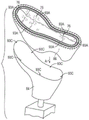
参照附图,其中,贯穿附图,相同的附图标记指代相同的部件,图1-4示出了用于鞋类物品12的包括在图8所示的中底布10中的聚合物囊16,该鞋类物品包括例如在图1中示出的鞋面14。中底布10包括如图8和10所示的聚合物囊16和楦鞋部件17。8和10。聚合物囊16限定内部空腔18(如图3所示),且被构造为将流体保持在内部空腔中。聚合物囊16具有绕内部空腔18的周边21的至少一部分延伸的周边凸缘20。在所示实施例中,周边凸缘20大体沿聚合物囊16的X-Y平面围绕整个周边21延伸(例如,向外围绕内部空腔18),其中,Z平面是聚合物囊16从聚合物囊16的近端表面24到聚合物囊16的远端表面26的高度,如图3所示。周边凸缘20围绕聚合物囊16的前足区域25、足中区域27和足跟区域29延伸,如图2所示。Referring to the drawings, in which like reference numerals refer to like parts throughout, FIGS. 1-4 illustrate a polymer for use in an article of
周边凸缘20限定沿周边凸缘20延伸的沟槽22。如在此进一步讨论的,当缝合或以其他方式将聚合物囊16固定至楦鞋部件17时,沟槽22用作操作者或包括机器人机器的机器的引导路径。在此所示和所述的一些实施例中,中底布10通过延伸穿过周边凸缘20的缝合部而被固定至鞋面14(例如,参见图27-34)。当将中底布10固定至鞋面14时,中底布10和鞋面14一起限定接收脚的空腔39,如图27所示。由接收脚的空腔39中的脚对鞋底结构80的动态压缩载荷如力FC所表示,其可以导致中底布10中围绕周边凸缘20的沿向外方向的张紧力,如图33中的向外力FO所表示,当张紧力随后释放且在此所述的系绳60返回到它们的张紧状态时,产生类似蹦床的效果。The
聚合物囊16包括第一聚合物片28和第二聚合物片30。第一聚合物片28在周边凸缘20处固定至第二聚合物片30,以包封内部空腔18。换句话说,当片28、30在周边凸缘20处固定在一起并且聚合物囊16被密封时,第一聚合物片28和第二聚合物片30将流体保持在内部空腔18中。如在此所用的,填充内部空腔18的“流体”可以是气体,诸如空气、氮气、另外的气体或其组合。The
第一和第二聚合物片28、30可以是能够弹性地保持诸如氮气、空气或另外的气体这样的流体的各种聚合物材料。用于第一和第二聚合物片28、30的聚合物材料的例子包括热塑性聚氨酯、聚氨酯、聚酯、聚酯聚氨酯和聚醚聚氨酯。此外,第一和第二聚合物片28、30可以每个由包括聚合物材料的不同材料层形成。在一个实施例中,第一和第二聚合物片28、30的每个由具有一个或多个热塑性聚氨酯层的薄膜形成,其带有对容纳在其中的加压流体不可渗透的乙烯和乙烯醇共聚物(EVOH)的一个或多个阻挡层,诸如包括阻气材料和弹性体材料的交替层的柔性微层膜,如授予Bonk等人的美国专利第6,082,025号和6,127,026号所公开的,其通过引用而整体并入本文。替换地,这些层可以包括乙烯-乙烯醇共聚物、热塑性聚氨酯、以及乙烯-乙烯醇共聚物和热塑性聚氨酯的再研磨材料。用于第一和第二聚合物片28、30的其他合适的材料在授予Rudy的美国专利第4,183,156号和第4,219,945号中公开,这些专利通过引用整体并入本文。用于第一和第二聚合物片28、30的其他合适材料包括包含结晶材料的热塑性薄膜,如授予Rudy的美国专利No.4,936,029和No.5,042,176所述的,以及包括聚酯多元醇的聚氨酯,如Bonk等人的美国专利No.6,013,340、6,203,868和6,321,465所述,这些专利通过引用将其整体并入本文。The first and
在选择用于中底布10的材料时,可以考虑工程特性,例如拉伸强度、拉伸特性、疲劳特性、动态模量和损耗角正切。例如,用于形成中底布10的第一和第二聚合物片28、30的厚度可以被选择,以提供这些特性。In selecting materials for
参考图4,周边凸缘20具有第一焊缝W1和与第一焊缝W1间隔开的第二焊缝W2。第一焊缝W1和第二焊缝W2使第一和第二聚合物片28、30在焊缝W1、W2处的界面32处彼此结合。焊缝W1和W2可以通过使用类似于图36-38的工具组件(也称为模具组件)形成,其包括第一和第二模具部分34A、34B以及模具插件34C,如图36所示。模具部分34A、34B在聚合物片28、30上闭合在一起,其中,拉伸部件50在聚合物片28、30之间。聚合物片28、30和拉伸部件50然后通过射频焊接(也称为高频或介电焊接)焊接或通过另外的热结合或粘合剂结合的方式固定,因为电源36提供产生加热聚合物片28、30的交变电场的能量,在那里,模具部分34A、34B或模具插件34C被施加到聚合物片28、30。Referring to FIG. 4 , the
在图36-38的模具组件中,焊缝W1、W2与向内突出的结合部70一样位于囊16的同一侧。在如图3所示的囊中,焊缝W1、W2与向内突出的结合部70一样位于囊16的相对侧。例如,这可以通过将模具插件34C固定至模具部分34A来实现。在周边凸缘20两侧具有焊缝W1、W2的实施例中,两个模具部分34A、34B将包括脊94、96。In the mold assembly of FIGS. 36-38 , welds W1 , W2 are on the same side of
第一焊缝W1和第二焊缝W2可沿周边凸缘纵向地延伸。如图1最佳地所示,第一焊缝W1和第二焊缝W2沿整个周边凸缘20延伸,并且在一些实施例中完全围绕(即,包围)内部空腔18。沟槽22在第一焊缝W1和第二焊缝W2之间沿周边凸缘20纵向地延伸。第一焊缝W1在沟槽22的内部侧。第二焊缝W2在沟槽22的外部侧。换句话说,第一焊缝W1在沟槽22的内部侧,第二焊缝W2在沟槽22的外部侧,其中,内部侧是朝向聚合物囊16的中心而外部侧是背离聚合物囊16的中心。The first weld W1 and the second weld W2 may extend longitudinally along the peripheral flange. As best shown in FIG. 1 , the first weld W1 and the second weld W2 extend along the
工具组件在焊缝W1和W2处的加热和压力可使第二聚合物片材30的一些材料移位,从而周边凸缘20可以包括在周边凸缘20的外表面(例如,远端表面)处在第一焊缝W1和沟槽22之间突出的第一脊38,以及在周边凸缘20的远端表面处在第二焊缝W2和沟槽22之间突出的第二脊40。The heat and pressure of the tool assembly at welds W1 and W2 can displace some material of
脊38、40有助于限定沟槽22的侧面。The
在一些实施例中,沟槽22在远端表面26中,当中底布10被固定至鞋面14时,该远端表面26是聚合物囊16的面向地那侧。在其他实施例中,沟槽22可以在近端侧(在近端表面24上),当中底布10被固定至鞋面14时,该远端表面26是聚合物囊16的面向脚那侧。因为聚合物片28、30可以是透明的,在沟槽22仅在近端侧设置的实施例中,沟槽22将通过在远端侧的周边凸缘20可以看到。在其他实施例中,远端表面26和近端表面24二者都具有这样的沟槽22,如图5中在凸缘20上所示。为周边凸缘20的两侧设置沟槽22有助于使得能够将聚合物囊16用于构造用于右脚的鞋类物品,以及可替代地用于构造用于左脚的鞋类物品。换句话说,中底布可以固定到用于右脚鞋类物品的鞋面,或者可以翻转,用于固定到用于左脚鞋类物品的鞋面。在任一情况下,两个沟槽22的一个在两种情况(例如,向外(背离鞋面)布置)下相对于鞋面将处于相同的位置,以用作缝合的引导件。在周边凸缘20的仅一侧具有沟槽22的实施例中,因为聚合物片28、30可以是透明的,即使在沟槽22仅在近端侧设置的实施例中,沟槽22在远端侧也将是可见的,反之亦然。In some embodiments,
如图3最佳地所示,拉伸部件50设置在内部空腔18中。拉伸部件50被固定至聚合物囊16的相对的内表面52、54。拉伸部件50包括第一拉伸层56、第二拉伸层58以及从第一拉伸层56到第二拉伸层58跨过内部空腔18的多个系绳60。系绳60将第一拉伸层56连接至第二拉伸层58。在图3中,仅一些系绳60用附图标记表示。系绳60也可以被称为织物拉伸构件或线,且可以具有连接第一拉伸层56和第二拉伸层58的滴线(drop thread)的形式。拉伸部件50可以形成为具有间隔编织织物的一体单件式织物元件。As best shown in FIG. 3 ,
第一拉伸层56结合至第一聚合物片28的内表面52,且第二拉伸层58结合到第二聚合物片30的内表面54。更具体地,第一表面结合部62将第一聚合物片28的内表面52连结至第一拉伸层56的外表面64。第二表面结合部66将第二聚合物片30的内表面54连结至与第一拉伸层56相对的第二拉伸层58的外表面68。表面52、64和表面54、68的整个界面部分彼此结合。A
系绳60将第一和第二聚合物片28、30的分离限制到图3所示的最大分离位置,该图3示出了聚合物囊16,其具有充气的内部空腔18,且该内部空腔18在内部空腔18中的气体的给定充气压力下密封,使得聚合物囊16处于充气状态。然而,应当理解,在制造在此所述的中底布10的方法200的一些实施例中,中底布10直到被固定至鞋面14之后才被充气和密封。在方法200的其他实施例中,中底布10可以在被固定至鞋面14之前被充气和密封。由于内部腔室18中的加压气体导致的在第一和第二聚合物片28、30上的向外力使系绳60处于张紧状态,且系绳60防止拉伸层56、58和聚合物片28、30进一步向外彼此远离。然而,系绳60在压缩负载下没有表现出抗压缩性。当鞋12在跑步或其他运动期间撞击地面、压力被施加在聚合物囊16上(例如由于穿用者的动态载荷的压缩力FC)时,如图27所示,聚合物囊16被压缩,并且随着系绳60与邻近特定系绳60的第一和第二聚合物片28、30上的载荷成比例地塌缩(例如,松弛),聚合物片28、30一起靠近移动。The
如图36所示,在将拉伸部件50结合至第一和第二聚合物片28、30之前,拉伸部件50的系绳60可以全部是初始长度,且在一些实施例中全都基本上是相同的长度,并且被系绳60连接的第一和第二拉伸层56、58可分别正好在系绳60的正上方具有大体平坦的外表面64、68。在图36中,系绳60以松弛状态示出,因为抗拉部件50不在密封的内部空腔内且不受到拉力,如在中底布10的聚合物囊16处于充气状态且不在动态压缩载荷下那样。As shown in FIG. 36, prior to bonding the
在在此提供的方法200下,尽管系绳60最初具有相同的长度,且第一和第二拉伸层56、58的外表面64、68以及第一和第二聚合物片28、30的表面24、26在形成中底布10之前在系绳正上方分别大体平坦(例如,没有轮廓),但是在一些实施例中,制造方法200产生向内突出的结合部70,该结合部70将第一聚合物片28连结至第一拉伸层56,且从第一聚合物片28向第二聚合物片30向内突出,直接伸入到由一些系绳60占据的内部空腔18的区域。实际上,存在多个向内突出的结合部70,如图2所示。每个向内突出的结合部70比第一表面结合部62朝向第二聚合物片30突出得更远。所述多个向内突出的结合部70从第一聚合物片28向内仅部分地跨过所述多个系绳60向第二聚合物片30突出,且聚合物囊16在向内突出的结合部70处变窄。例如,结合部可以通过焊接工艺形成,诸如使用工具的射频或超声焊接,其在聚合物囊16中导致热结合。每个向内突出的结合部70由诸如图36和38的模具插件34C这样的模具部件的相应突出部72产生。在在此公开的制造方法200期间,突出部72接触第一聚合物片28。图38示出了代表性的模具插件34C,其具有带第一图案的突出部72,其导致向内突出的结合部70在图2所示的聚合物囊的近端表面24处的结合部图案,尽管对于焊缝W1、W2在囊16的与向内突出的结合部相同一侧的实施例,模具插件34C被示出为固定至模具部分34B。模具插件34C也可以被称为垫片。Under the
向内突出的结合部70在第一聚合物片28的近端表面24处导致凹陷的沟槽74。在所示的实施例中,向内突出的结合部70仅在第一聚合物片28处。在其他实施例中,诸如模具插件34C这样的模具插件可以被邻近第一聚合物片28和第二聚合物片30两者放置,以在第二聚合物片30处提供向内突出的结合部70,作为在第一聚合物片28处的向内突出的结合部70的替代或补充。在其他实施例中,诸如图6和7所示的囊16AA,在第一和第二聚合物片28、30的任一个处都没有形成向内突出的结合部70。The inwardly protruding
如图3所示,每个向内突出的结合部70部分地横过多个系绳60。换句话说,向内突出的结合部70直接在不同系绳60的外侧并且在那些系绳60上向内突出。系绳60可以被成排布置,每排在拉伸层56、58之间横向地延伸,或者以系绳60在拉伸层56、58之间延伸的任何其他图案布置。各个不同的系绳60与向内突出的结合部70对齐。向内突出的结合部70可以横过系绳60的不同排,使得来自不同排的不同系绳60与一向内突出的结合部70对齐(例如,在其下方或上方),或者向内突出的结合部70可以与单排直接对齐。一些向内突出的结合部70可以在系绳的排之间。As shown in FIG. 3 , each inwardly projecting
因为向内凸出的结合部70至少部分地横过所述多个系绳60,在一个或多个实施例中并参考图3,所述多个系绳60包括与向内突出的结合部70的一个对齐的系绳60A和被每个向内突出的结合部70移位的系绳60B。仅一些系绳60A、60B在图3中标记。与向内突出的结合部70对齐的系绳60A通过热、通过第一拉伸层56的材料的覆盖的压缩和/或通过覆盖系绳60A的第一拉伸层56的覆盖材料而变形,使得系绳60A在向内突出的结合部70处比其他地方更短、更厚、或者既更短又更厚。这样的系绳在图3中用附图标记60A表示,且可以被称为改进的系绳60A。但是,在此对系绳60的提及包括系绳60A和系绳60B,除非另有说明。Because the inwardly protruding
当内部空腔18被充气时,改进的系绳60A在第一聚合物片28的近端表面24中导致凹陷的沟槽74,如图2和3所示。当内部空腔18中的气体的充气压力足以使所述多个系绳60张紧时,向内突出的结合部70在第一聚合物片28的近端表面24处限定沟槽74。在每个沟槽74处,聚合物囊16被分为在沟槽74的一侧的第一物品部分11和在沟槽74的另一侧的第二物品部分13,如图3所示。第一物品部分11沿沟槽74相对于第二物品部分13铰接。换句话说,在向内突出的结合部70的第一侧处的第一聚合物片28的近端表面24与在向内突出的结合部70的第二侧处的第一聚合物片28的近端表面24是非平面的,第二侧与第一侧相对。When the
改进的系绳60A的张紧力还在第二聚合物片30的远端表面26中导致沟槽76。当内部空腔18被充气时,第二聚合物片30朝相对应的沟槽74和每个凹部76处的向内突出的结合部70向内凹入。The tension of the
第一聚合物片28和第一拉伸层56的物理变形与改进的系绳60A的张紧力相结合将使沟槽74比凹部76更深,这仅是由于缩短的改进系绳60A的张紧力导致。因此,聚合物囊16可具有铰接的形状,例如当充气时,没有与其他部件组装或受其约束,且不在负载下,导致聚合物囊16在近端表面24处略微凹入并且在远端表面26处略微凸起。由于沟槽74和凹部76一起促使聚合物囊16的铰接在沟槽74处发生,随着聚合物囊16的总厚度在沟槽74处减小,因此,中底布10将被偏压到铰接形状,在沟槽74处降低中底布10的弯曲刚度。The physical deformation of the
沟槽74用作中底布10的屈曲轴线,从而当中底布10被包括在如图28所示的鞋类物品12的鞋底结构80中时,增加鞋底结构80的柔性。向内突出的结合部70和所得的沟槽74可以建立屈曲轴线,其中一些屈曲轴线可以与脚的关节对齐,例如跖指关节。由向内突出的结合部70和沟槽74产生的屈曲轴线沿近端表面24侧向和纵向地延伸,并且可以增加中底布10的横向(即,侧向)和纵向柔性。在一个或多个实施例中,诸如图2所示,每个向内突出的结合部70沿第一聚合物片28的外表面24大体直地延伸,并且向内突出的结合部70的中心轴线在第一聚合物片28的近端表面24处相对于彼此平行或正交地布置。
在其他实施例中,向内突出的结合部可以其他图案布置。例如,为模具插件提供与图21所示不同的突出部72的布置将导致向内突出的结合部70的不同图案。向内突出的结合部的替代图案的一个例子在图45中示出,如在此所述。In other embodiments, the inwardly protruding bonds may be arranged in other patterns. For example, providing a mold insert with a different arrangement of
参考图3,每个向内突出的结合部70与第二聚合物片30间隔开,使得内部空腔18在向内突出的结合部70变窄但没有关闭,并且内部空腔18中的气体仍可以跨过向内突出的结合部70流体地连通。第一拉伸层56在与向内突出的结合部70邻近的系绳60B处与第二拉伸层58隔开第一距离D1,且向内突出的结合部70与第二拉伸层58隔开第二距离D2,其可以是向内突出的结合部70和第二拉伸层58之间的最小距离(即,在向内突出的结合部70下方的内部空腔18的最狭窄部分处的距离)。在一实施例中,制造方法200的部分200A可以被控制为使得,第二距离D2为第一距离D1的50%至80%。例如,可影响向内突出的结合部70及其朝向第二聚合物片30突出的程度的因素可以被控制,以提供第二距离D2与第一距离D1的该期望比率。这样的因素可以包括产生向内突出的结合部70的突出部72的深度、模具插件34C或其他模具部件的温度、中底布10的部件的温度、在制造期间模具空腔中的真空和/或充气压力、焊接功率或焊接频率(如果使用射频焊接的话)以及其他因素。Referring to FIG. 3 , each inwardly protruding joint 70 is spaced apart from the
因此,内部空腔18的在向内突出的结合部70第一侧的部分与内部空腔18的在向内突出的结合部70第二侧的部分流体连通,第二侧与第一侧相对,如图3所示。在两个部分之间的向内突出的接合部70下方延伸的所示的改进系绳60A的直径狭窄,且允许气体在系绳60A周围和之间流动。当压缩力FC被施加到中底布10时,例如如图28所示在鞋类物品12与地面G撞击期间,这允许气体从系绳60A的一侧的内部空腔18移位至系绳60A的另一侧的内部空腔18。例如,当脚在脚部撞击期间从脚跟向脚趾向前滚动时,气体可从中底布10中靠后部分移动到中底布10中更靠前的部分。由内部空腔18中的流体提供的支撑缓冲因此可以在使用中底布10期间最需要的区域中提供。Accordingly, the portion of the
图33示出了鞋12E的实施例,其中,保护性覆盖层85在中底布10的近端侧上固定。保护性覆盖层85由此将被布置在接收脚空腔39内。保护性覆盖层85可以是抗磨损材料,其针对剪切力和/或尖锐物品保护聚合物囊16。保护性覆盖层可以由例如聚合物片、织物层或其他保护层形成,除了针对尖锐物体保护囊16之外,其可以针对剪切力保护囊16(例如,通过最小化(或保持足够低的)囊16和保护性覆盖层85的耐磨材料之间的摩擦系数)。FIG. 33 shows an embodiment of a
图6-26示出了在本教导的范围内的中底布10、10AA、10A、10B、10C、10D、10E、10F、10G、10H、10I的各个实施例。每个中底布包括聚合物囊16、16A、16B、16D、16E、16F、16G、16H或16I,该聚合物囊配置有具有沟槽22的凸缘20以及拉伸部件50,如关于图1-3所描述的。6-26 illustrate various embodiments of
每个中底布还包括固定至聚合物囊的楦鞋部件。在内部空腔18中具有拉伸部件50的聚合物囊和固定至聚合物囊的楦鞋部件一起构成成形的中底布,其随后被固定至鞋面,如在此所述。Each midsole also includes a last component secured to the polymer bladder. The polymeric bladder with the
参考图8-10,中底布10包括图1-4的在其中具有拉伸部件50的聚合物囊16和固定至周边凸缘20的楦鞋部件17。更具体地,楦鞋部件17(以及在此公开的任何其他楦鞋部件)可以是织造或无纺布织物、弹性体或带有织物层的泡沫中的一种。楦鞋部件17比聚合物囊16的在内部空腔18中具有拉伸部件50的部分的高度更薄(即,不那么高),且在将中底布10缝合至鞋面期间可更容易抓握。通过添加一个或多个楦鞋部件,由于缝合引起的囊上的应力可以被最小化。Referring to FIGS. 8-10 , the
如图10所示,楦鞋部件17具有孔口19。孔口19的尺寸被设置成使得,聚合物囊16部分地延伸穿过孔口19,且周边凸缘20围绕孔口19邻接楦鞋部件17。例如,如图27所示,楦鞋部件17覆盖并邻接凸缘20,且第二聚合物片30在聚合物囊16的充气部分处的部分延伸穿过孔口19。如图8和27最佳地所示,凸缘20的外边缘90从孔口19向外侧向地延伸,且楦鞋部件17的外边缘91从凸缘20的外边缘90向外侧向地延伸。外边缘90沿图10中的虚线边界91A下落。换句话说,聚合物囊16比孔口19更宽,楦鞋部件17比聚合物囊16更宽。在图29和30所示的替换实施例中,楦鞋部件17A在所有方面都与楦鞋部件17相似,除了它与聚合物囊16的宽度相同,使得其外边缘91与聚合物囊16的外边缘90对齐。As shown in FIG. 10 , the shoe
楦鞋部件17被配置为沿周边凸缘20围绕内部空腔18的周边21延伸。在图8-10和27-30所示的实施例中,楦鞋部件17具有与聚合物囊16的前足区域25、足中区域27和足跟区域29相对应的前足区域25、足中区域27和足跟区域29。孔口19和聚合物囊16在前足区域25、足中区域27和足跟区域29的每一个中延伸。The shoe
楦鞋部件17具有定位特征部93G,其可以是楦鞋部件17中的孔口或标记,或者是楦鞋部件17的周边边缘中的凹口或该处的突出部,其以与聚合物囊16的凹口93A或其他定位特征部相同的相对间隔而彼此间隔开。当将聚合物囊16被放置在孔口19处时,定位特征部93A与定位特征部93G对齐。这将凸缘20相对于楦鞋部件17正确地定位,用于随后穿过凸缘20缝合。替代地,代替凹口93A或除了凹口93A之外,在聚合物囊16上的定位特征部可以是一个或多个穿过凸缘20焊接的孔口93D,如图33-38所示。在一些实施例中,对齐图案可以被印刷在聚合物囊16上,且用于与楦鞋部件17、鞋面14或鞋楦84的相应对齐特征部对齐。除了促进聚合物囊16、16B等的柔性之外,向内突出的结合部70的焊接图案(例如,所得沟槽74和凹部76的图案)可以用于与楦鞋部件17、鞋楦84和/或鞋面14对齐,类似于印刷的对齐图案。
楦鞋部件17用针脚被缝合或以其他方式固定至聚合物囊16,所述针脚在沟槽22处延伸穿过凸缘20。当缝合或以其他方式将楦鞋部件17固定至聚合物囊16时,沟槽22用作操作者或包括机器人机器的机器的引导路径。如图8和27所示,第一系列针脚81延伸穿过楦鞋部件17并在沟槽22中穿过周边凸缘20,且将楦鞋部件17固定至聚合物囊16。第一系列针脚81和沟槽22都完全围绕聚合物囊16的内部空腔18的周边21且在外侧延伸。仅一些针脚81用附图标记表示。
如图27所示,具有固定至楦鞋部件17的聚合物囊16的中底布10通过第二系列针脚82被固定到鞋面14,该第二系列针脚82延伸穿过楦鞋部件17和鞋面14、但不穿过聚合物囊16。As shown in FIG. 27 , the
图12-14示出了中底布10A的另一实施例,其包括其中具有拉伸部件50的聚合物囊16A和通过第一系列针脚81固定至聚合物囊16A的周边凸缘20的楦鞋部件17A,该第一系列针脚81延伸穿过周边凸缘20和楦鞋部件17A。第一系列针脚81和沟槽22都完全围绕内部空腔18的周边21且在外侧延伸。12-14 illustrate another embodiment of a
如图14所示,楦鞋部件17A具有孔口19A。孔口19A的尺寸被设置成使得,聚合物囊16A部分地延伸穿过孔口19A,且周边凸缘20围绕孔口19A邻接楦鞋部件17A,类似于图27所示的楦鞋部件17和凸缘20。凸缘20的外边缘90从孔口19A向外侧向地延伸,且楦鞋部件17A的外边缘91从凸缘20的外边缘90向外侧向地延伸。As shown in FIG. 14, the shoe
楦鞋部件17A被配置为沿周边凸缘20围绕内部空腔18的周边21延伸。在图12-14的实施例中,楦鞋部件17A具有前足部分25、足中部分27和足跟部分29。孔口19A在前足区域25中延伸,且可在足中区域27中部分地延伸。如果孔口延伸到足中区域27中但没有在足跟区域29中延伸,则聚合物囊16A被构造为在前足区域25中延伸且在足中区域27中部分地延伸。The shoe
楦鞋部件17A具有定位特征部93G,其可以是楦鞋部件17A中的孔口或其上的标记,或者是界定孔口19A的楦鞋部件17A的内周边边缘中的凹口或该处的突出部,其以与聚合物囊16A的凹口93A或其他定位特征部相同的相对间隔而彼此间隔开。当将聚合物囊16A被放置在孔口19A处时,定位特征部93A与定位特征部93G对齐。类似于楦鞋部件17,楦鞋部件17A用第一系列针脚81被缝合或以其他方式固定至聚合物囊16A,所述针脚在沟槽22处延伸穿过凸缘20。第一系列针脚81和沟槽22都完全围绕聚合物囊16A的内部空腔18的周边21且在外侧延伸。类似于中底布10,具有固定至楦鞋部件17A的聚合物囊16A的中底布10A可通过第二系列针脚82被固定到鞋面14,该第二系列针脚82延伸穿过楦鞋部件17A和鞋面14、但不穿过聚合物囊16A。
图15-17示出了中底布10B的另一实施例,其包括其中具有拉伸部件50的聚合物囊16B和通过第一系列针脚81固定至聚合物囊16B的周边凸缘20的楦鞋部件17B,该第一系列针脚81延伸穿过周边凸缘20和楦鞋部件17B。第一系列针脚81和沟槽22都完全围绕内部空腔18的周边21且在外侧延伸。FIGS. 15-17 illustrate another embodiment of a
如图17所示,楦鞋部件17B具有孔口19B。孔口19B的尺寸被设置成使得,聚合物囊16B部分地延伸穿过孔口19B,且周边凸缘20围绕孔口19B邻接楦鞋部件17B,类似于图25所示的楦鞋部件17和凸缘20。凸缘20的外边缘90从孔口19B向外侧向地延伸,且楦鞋部件17B的外边缘91从凸缘20的外边缘90向外侧向地延伸。As shown in Fig. 17, the shoe
楦鞋部件17B被配置为沿周边凸缘20围绕内部空腔18的周边21延伸。在图15-17的实施例中,楦鞋部件17B具有前足部分25、足中部分27和足跟部分29。孔口19B在足跟区域29中延伸。聚合物囊16B被构造为在足跟区域29中延伸,但没有在足中区域27或前足区域25中延伸。The
楦鞋部件17B具有定位特征部93G,其可以是楦鞋部件17B中的孔口或其上的标记,或者是界定孔口19B的楦鞋部件17B的内周边边缘中的凹口或该处的突出部,其以与聚合物囊16B的凹口93A或其他定位特征部相同的相对间隔而彼此间隔开。当将聚合物囊16B被放置在孔口19B处时,定位特征部93A与定位特征部93G对齐。类似于楦鞋部件17,楦鞋部件17B用第一系列针脚81被缝合或以其他方式固定至聚合物囊16B,所述针脚在沟槽22处延伸穿过凸缘20。第一系列针脚81和沟槽22都完全围绕聚合物囊16B的内部空腔18的周边21且在外侧延伸。类似于中底布10,具有固定至楦鞋部件17B的聚合物囊16B的中底布10B可通过第二系列针脚82被固定到鞋面14,该第二系列针脚82延伸穿过楦鞋部件17B和鞋面14、但不穿过聚合物囊16B。
图18-20和31-32示出了中底布10C的另一实施例,其包括其中具有拉伸部件50的聚合物囊16和通过第一系列针脚81固定至聚合物囊16的周边凸缘20的楦鞋部件17C,该第一系列针脚81延伸穿过周边凸缘20和楦鞋部件17C。第一系列针脚81和沟槽22都完全围绕内部空腔18的周边21且在外侧延伸。18-20 and 31-32 illustrate another embodiment of a
如图31所示,楦鞋部件17C的尺寸被设置为使得,周边凸缘20邻接楦鞋部件17C,楦鞋部件17C在聚合物囊的内侧21和聚合物囊的外侧33之间覆盖和跨过聚合物囊16延伸。如图31最佳地所示,因为聚合物囊16和楦鞋部件17C是相同宽度,凸缘20的外边缘90与楦鞋部件17C的外边缘91对齐。楦鞋部件17C被配置为沿周边凸缘20围绕内部空腔18的周边21延伸。在图18-20所示的实施例中,楦鞋部件17C和聚合物囊16二者具有前足区域25、足中区域27和足跟区域29,且楦鞋部件17C不具有聚合物囊16延伸穿过的孔口。As shown in FIG. 31 , the
楦鞋部件17C具有定位特征部93G,其可以是楦鞋部件17C的外周边中的孔口或凹口或在该处突出部,其以与聚合物囊16的凹口93A或其他定位特征部相同的相对间隔而彼此间隔开。当楦鞋部件17C抵靠聚合物囊16布置、且楦鞋部件17C通过第一系列针脚81(其延伸穿过凸缘20且在沟槽22处穿过楦鞋部件17C)被缝合至聚合物囊16时,定位特征部93A与定位特征部93G对齐。第一系列针脚81和沟槽22都完全围绕聚合物囊16的内部空腔18的周边21且在外侧延伸。不像中底布10,具有固定至楦鞋部件17C的聚合物囊16的中底布10C通过第二系列针脚82被固定到鞋面14,该第二系列针脚82延伸穿过楦鞋部件17C和鞋面14、且还在沟槽22中穿过聚合物囊16的凸缘20,如图31所示。第一系列针脚81和第二系列针脚82均在沟槽22中延伸穿过聚合物囊16。
在一些实施例中,楦鞋部件和聚合物囊二者都延伸中底布的整个宽度,但都没有延伸整个长度,并且楦鞋部件和聚合物囊沿中底布纵向地布置。例如,在图21-26的实施例中,聚合物囊和楦鞋部件每个布置在中底布的前足区域、足中区域和足跟区域中的至少一个不同区域中,且楦鞋部件通过第一系列针脚固定至聚合物囊,该第一系列针脚横向地跨过聚合物囊和楦鞋部件延伸。In some embodiments, both the last component and the polymeric bladder extend the full width of the midsole, but neither extends the full length, and the last component and the polymeric bladder are arranged longitudinally along the midsole. For example, in the embodiment of FIGS. 21-26 , the polymeric bladder and the last component are each disposed in at least one different region of the midsole fabric in the forefoot, midfoot, and heel regions, and the last component passes through A first series of stitches is secured to the polymer bladder, the first series of stitches extending laterally across the polymer bladder and the last component.
参考图21,聚合物囊16D布置在前足区域25中,且可略微延伸到足中区域27中。楦鞋部件17D在足跟区域29和足中区域27中延伸,在那里,楦鞋部件17D的前横向边缘23邻接或稍微重叠于聚合物囊16D的后横向边缘90D。沟槽22没有在后横向边缘90D处跨过聚合物囊16D延伸。聚合物囊16D可通过切割聚合物囊16并添加横向延伸的焊缝W3以在切割的地方密封内部腔体18而形成。第一系列针脚81横向地跨过中底布10D在焊缝W3后方穿过聚合物囊16D延伸,以将楦鞋部件17D固定至聚合物囊16D。随后的将中底布10D固定至鞋面14的第二系列针脚将在沟槽22中穿过聚合物囊16D围绕聚合物囊16D延伸到后横向边缘90D,并且将在所述系列针脚81后方在外边缘91附近围绕楦鞋部件17D继续。Referring to FIG. 21 ,
当将中底布10D固定至鞋面14时,聚合物囊16D的定位特征部(例如,凹口93A、突出部、囊的向内突出的结合部70的图案或囊上的印刷对准图案)和楦鞋部件17D的定位特征部93G用于将中底布10D与鞋面14对齐。聚合物囊16D的外边缘90在前足区域25中以及在足中区域27的前部部分中形成中底布10D的外边缘,且楦鞋部件17D的外边缘91在足中区域27的后部部分以及在足跟区域29中形成中底布的外边缘。When securing the
当固定到鞋面14时,中底布10D的横截面图如图34和35所示。在前足区域25(图34)中,中底布10D仅包括聚合物囊16D和拉伸部件50。在足跟区域(图35)中,中底布10D仅包括楦鞋部件17D。鞋类物品12D包括鞋底结构80,该鞋底结构80包括中底83(在图34和35中未示出),该中底83将在聚合物囊16D处被固定至聚合物囊16D的远端侧和鞋面14的下端部,且在楦鞋部件17D处固定至楦鞋部件17D的远端侧和鞋面14的下端部。A cross-sectional view of
图22示出与关于中底布10D所述相同构造的中底布10E,但是聚合物囊16D被聚合物囊16E替代,该聚合物囊16E具有凸缘20,该凸缘20具有完全围绕聚合物囊16E延伸的沟槽22,包括在后横向边缘90D处。换句话说,聚合物囊16E被形成为所示的尺寸,而不是从较长的聚合物囊16切割、然后在焊缝W3处焊接。在后横向边缘90D处固定楦鞋部件17D的第一系列针脚81在沟槽22处延伸穿过凸缘20。FIG. 22 shows a
图23示出了中底布10F,其具有在后横向边缘90D处以及在前横向边缘90F处从聚合物囊16切割的聚合物囊16F。聚合物囊16F在焊缝W3处以及在焊缝W4处被焊接,以密封内部空腔18。第一系列针脚包括针脚81A,其横向地跨过中底布10F在焊缝W3后方穿过聚合物囊16F延伸,以将后楦鞋部件17F2固定至聚合物囊16F。第一系列针脚包括针脚81B,其横向地跨过中底布10F在焊缝W4前方穿过聚合物囊16F延伸,以将前楦鞋部件17F1固定至聚合物囊16F。随后的将中底布10F固定至鞋面14的第二系列针脚将在聚合物囊袋16F的内侧31和外侧33处在沟槽22中延伸穿过聚合物囊16F,且将在所述系列针脚81A后方在外边缘91附近围绕后楦鞋部件17F2并在针脚81B前方围绕楦鞋附件17F1继续。楦鞋部件17F1和17F2的外边缘91以及聚合物囊16F的外边缘90形成中底布10F的外边缘。楦鞋部件17F1、17F2每个都具有至少一个定位特征部93G,其是当将中底布10F缝合至鞋面14时可以与鞋面14上的类似间隔的定位特征部对齐的孔或凹口(或突出部或标记),如同凹口93A或其他定位特征部一样。Figure 23 shows
图24示出与关于中底布10F所述相同构造的中底布10G,但是聚合物囊16F被聚合物囊16G替代,该聚合物囊16G具有凸缘20,该凸缘20具有完全围绕聚合物囊16G延伸的沟槽22,包括在后横向边缘90D处和在前横向边缘90F处。换句话说,聚合物囊16G被形成为所示的尺寸,而不是从较长的聚合物囊16切割、然后在焊缝W3和W4处焊接。在后横向边缘90D和前横向边缘90F处固定楦鞋部件17F2、17F1的第一系列针脚81A、81B在沟槽22处分别延伸穿过凸缘20。FIG. 24 shows a
图25示出与中底布10D类似地构造的中底布10H,但是聚合物囊16H位于足跟区域29和足中区域27的后部部分中,且楦鞋部件17H位于前足区域25和足中区域27的前部部分中。聚合物囊16H可以从聚合物囊16切割且在横向焊缝W5处焊接以密封内部空腔18,然后楦鞋部件17H在聚合物囊16H的前横向边缘90G处通过第一系列针脚81被缝合至聚合物囊16H,该第一系列针脚从聚合物囊16H的内侧31向外侧33横向地跨过中底布10H延伸,并在焊缝W5前方。25 shows a
图26示出与关于中底布10H所述相同构造的中底布10I,但是聚合物囊16H被聚合物囊16I替代,该聚合物囊16I具有凸缘20,该凸缘20具有完全围绕聚合物囊16I延伸的沟槽22,包括在前横向边缘90G处。换句话说,聚合物囊16I被形成为所示的尺寸,而不是从较长的聚合物囊16切割、然后在焊缝W5处焊接。将楦鞋部件17H固定至聚合物囊161I的第一系列针脚81在沟槽22处在后横向边缘90D附近延伸穿过凸缘20。Figure 26 shows a midsole 10I of the same construction as described with respect to
在鞋类物品12A、12C和12D中,聚合物囊16、16D通过在沟槽22处延伸穿过凸缘20的针脚82被直接固定至鞋面14。这些构造将倾向于在动态压缩期间将沿X-Y平面的聚合物囊比鞋类物品12的聚合物囊16约束到更大的程度,鞋类物品12的聚合物囊16没有直接固定至鞋面14,而是通过第一系列针脚81固定至楦鞋部件17,且针脚82仅延伸穿过楦鞋部件17和鞋面14。In articles of
在每个实施例中,如图42-43所示,在将鞋楦84放置在由鞋面14形成的开口86中之前,中底布10或任意中底布10AA-10I可被固定至鞋面14,如所述。换句话说,直到将鞋面14固定至中底布10,鞋面14才被防止在鞋楦84上。提高制造效率所期望的是,准确且相对较快地完成将中底布10固定至鞋面14。在该过程期间,中底布10或10AA-10I中任一个都相对于缝针移动,或反之亦然,以使得针沿楦鞋部件和/或沟槽22(取决于实施例,如在此所述的)移动,且针脚82也沿之前进。In each embodiment, as shown in FIGS. 42-43 ,
为了进一步改进将鞋面14缝合至中底布10或10AA-10I中任一个的效率,当发生缝合时,聚合物囊可以处于未充气状态。例如,如图39所示,当聚合物囊16与鞋面14对齐时,聚合物囊16未充气,然后缝合至图40中的鞋面14。当处于未充气状态时,聚合物囊16更具柔性,使得可以相对于提供针脚82的缝纫机而言,更容易操作中底布10或10AA-10I中任一个。在通过所述系列针脚82将鞋面14固定至中底布10之后,聚合物囊16被充气至预定压力,或者在不充气的情况下使其处于环境压力,然后内部空腔18通过塞住聚合物囊16的端口或填充管而被密封。充气和密封可在将具有缝合至其的中底布10的鞋面14放置在鞋楦84上之前进行,因为在其充气状态下,中底布10和鞋面14更能代表附连鞋底结构80之前的最终相对构造,且可因此当鞋底结构80的中底83被固定至中底布10的远端表面26和/或鞋面14的下周边时允许在鞋楦84上的更准确放置。在其他实施例中,在将诸如囊16的囊固定至鞋面14之前,囊16可以被充气和密封。To further improve the efficiency of stitching upper 14 to either
为了提高将中底布10(或任一中底布10AA-10I)和鞋面14定位在鞋楦84上的速度和精度,中底布10或10AA-10I中任一个可配置有定位特征部,如所讨论的。例如,如图39所示,楦鞋部件17可具有围绕外边缘91间隔开的凹口93F。例如,凹口93F可通过切割形成。囊16中的凹口93A可通过模具部分34A、34B或模具插件34C形成,或可以其他方式被设置。如图36和38所示,模具部分34B具有连续的内脊94和外脊96,它们彼此间隔开并且一起形成焊缝W1和W2。外脊96具有凹口98,在图38中最佳地示出,其至少部分地形成聚合物囊16的凹口93A。在其他实施例中,囊16的定位特征部或楦鞋部件17的定位特征部可以是突出部、孔口、印刷标记等。在如图6所示的囊16AA的实施例中,凸缘20具有定位特征部93H,其是在周边凸缘20的外边缘90处的突出部。在其他实施例中,可以使用凹口和突出部的组合或其他标记。通常,可以例如通过焊接、切割、冲压、印刷、染色等提供在此所述的各种定位特征部。To improve the speed and accuracy with which midsole 10 (or any midsole 10AA-10I) and upper 14 are positioned on shoe last 84, either
更进一步,可以使用激光,以将中底布10或10AA-10I中任一个的特征部与鞋楦84对齐。可以使用单独的夹具将中底布10或10AA-10I中任一个与鞋面14的周边对齐。在一些实施例中,脚跟中心(在周边凸缘的边缘处)可以鞋楦上的特征部对齐。此外,在一些实施例中,图案可以印刷在中底布10或10AA-10I中任一个上,然后其可以与鞋楦84上的图案对齐。例如,中底布10的远端侧可以具有在其上印刷的对齐图案,因为该侧将被附连至中底83,使得印刷的图案在鞋类物品成品中将是不可见的。在一些实施例中,印刷的对齐图案还可用于与鞋面14的相应对齐特征部对齐。除了促进中底布10、10AA-10I等的柔性之外,向内突出的结合部70的焊接图案(例如,所得沟槽74和凹部76的图案)可以用于与楦鞋部件17、鞋楦84和/或鞋面14对齐,正如印刷的对齐图案可被用于对齐目的。例如在此所述的向内突出的结合部70的图案可以与鞋楦84上的激光图案(例如,光图案)以与中底布上的印刷对齐图案相同的方式对齐。Still further, a laser may be used to align features of
鞋面14可以具有定位特征部,所述定位特征部是沿缝合至中底布10或10AA-10I中任一个的其下部周边间隔开的标记、凹口、突出部或孔口。鞋面14的定位特征部具有与中底布10或10AA-10I中任一个的定位特征部(例如,凹口93F)相同的相对间隔。在缝合期间,操作员可以将鞋面14的定位特征部与中底布10的定位特征部对齐。在图39中,鞋面14被示出为具有定位特征部(例如,标记或孔口93B),其可以为此目的与中底布10或10AA-10I任一个的定位特征部(例如,凹口93F)对齐。替代地或另外,鞋楦84可以配置有定位特征部,该定位特征部具有与中底布10或10AA-10I中任一个的定位特征部相同的相对间隔。如图42所示,定位特征部93C可例如是在鞋楦84上的标记或其中的孔口。在另一实施例中,鞋楦84可以具有与中底布10或10AA-10I中任一个的焊接图案(例如,向内突出的结合部70的图案)对齐的标记。应当理解,当中底布10处于未充气状态时,中底布10上的定位特征部具有与当中底布10处于充气状态时略微不同的相对间隔。相应地,中底布10上的定位特征部在充气状态下具有的相对间隔可以与当中底布10在未充气状态下固定至鞋面14和在充气状态下放置在鞋楦84上时鞋楦84上的定位特征部相同的相对间隔,如在此所述的。
图44的流程图中示出制造包括任一中底布10、10AA-10I的鞋和在此所述的鞋类物品的方法200的步骤,所述鞋类物品诸如鞋类物品12、12A、12C、12D。The steps of a
方法200的部分200A包括设置中底布10、10AA-10I等的步骤206。设置中底布可以包括形成中底布。在方法200的其他实施例中,当在步骤206中设置时,中底布10、10AA-10I等可已经处于成型状态(例如,中底布可以在步骤206下以成型状态获得)。因此,设置中底布的实体既可以形成中底布、也可以将其组装在鞋中,或者单独的实体可以形成中底布,而执行方法200的实体可以获得成型的中底布以执行方法200。因此,设置步骤206可以包括或可以不包括形成中底布。
在包括形成中底布的实施例中,步骤206可以包括子步骤,在该子步骤中,第二聚合物片30被放置在拉伸部件50上。换句话说,拉伸部件50在聚合物片28、30之间。In embodiments that include forming a midsole,
接下来,步骤206可以包括子步骤,在该子步骤中,第一和第二聚合物片28、30在周边凸缘20中在第一和第二焊缝W1、W2处焊接在一起,以形成具有内部空腔18的聚合物囊16,且由于焊缝W1、W2产生脊38、40,沟槽22形成在周边凸缘20中。如之前所讨论的,焊接可以是射频焊接,当模具部分(例如模具部分34A,34B(和模具插件34C))在聚合物片28、30上一起闭合且电源36提供产生加热聚合物片28、30的交变电场的能量时,在模具部分34A、34B和/或模具插件34C被施加到聚合物片28、30之处产生焊缝,此时该射频焊接完成。Next,
与焊接焊缝W1、W2分开或同时地,方法200的部分200A可以包括经由模具插件34C的突出部72通过射频焊接来焊接向内突出的结合部70的子步骤。例如,当模具部分34A、34B闭合在一起时,如果模具插件34C位于形成在模具部分34A、34B之间的模具空腔中,则向内突出的结合部70将与焊缝W1、W2同时提供。Separately or simultaneously with welding welds W1 , W2 ,
方法200的部分200A可包括在中底布10上设置一个或多个定位特征部的步骤,所述定位特征部诸如凹口93A、突出部93H(例如,参见中底布10A)、焊接图案(例如,向内突出的结合部70的图案)或标记(例如,对齐线的印刷图案)或孔口、均作为定位特征93D表示的标记或孔口。在一些实施例中,定位特征部可以在包含在如所述的设置中底布的步骤206中的射频焊接期间被设置。替代地,凹口93A、突出部93H或孔口93D可以在单独的后续步骤中被切割、冲压、印刷、焊接或以其他方式形成。
对于一些中底布10、10AA、10A、10B,方法200的部分200A可以包括在楦鞋部件中切割孔口的步骤,所述孔口诸如楦鞋部件17、17A中的孔口19、19A、19B。For some
方法200的部分200A可以包括将聚合物囊16、16A、16B分别放置在孔口19、19A、19B处的步骤。
方法200的部分200A可以包括步骤216,将聚合物囊与楦鞋部件对齐,诸如通过将聚合物囊16、16A、16B的一个或多个定位特征部93A(例如,凹口、突出部、焊接图案、印刷图案、孔口)与楦鞋部件17、17A、17B的一个或多个定位特征部93G对齐。
一旦聚合物囊和楦鞋部件在步骤216中对齐,方法200的部分200A可以进行到步骤218,楦鞋部件可以被固定至聚合物囊,诸如在周边凸缘20处或在边缘90D、90F、90G处,如关于不同实施例所述的,诸如通过将第一系列针脚81穿过楦鞋部件和聚合物囊缝合。Once the polymeric bladder and last shoe part are aligned in
在图44的流程图中描绘的制造鞋的方法200可以包括:根据制造中底布10的方法200的部分200A(例如,可包括步骤206-218)形成中底布10,且然后进行到制造鞋类物品的方法200的部分200B;或者通过以预先成型的中底布开始(例如,从步骤220开始)仅包括制造鞋类物品的方法200的部分200B。The
参考图39,中底布10的定位特征部(例如,凹口93F)可以与鞋面14的定位特征部(例如,孔口或标记93B)对齐,然后在步骤220中,中底布10可以被固定至鞋面14上,诸如通过延伸穿过楦鞋部件(诸如图39中的楦鞋部件17)的所述系列针脚82。针脚82被称为第二系列针脚,且在一些实施例中,可以仅延伸穿过楦鞋部件和鞋面14,诸如在中底布10、10AA、10A、10B、10C中。在其他实施例中,针脚82还可以在一些实施例中在周边凸缘20中沿沟槽22延伸穿过聚合物囊,诸如在图29、31和34的鞋12A、12C和12D中。Referring to FIG. 39 , the positioning features (eg,
在步骤220之前或与之同时,保护性覆盖层85可被固定在中底布10上,例如通过缝合,如图33所示。在示例实施例中,保护性覆盖层85可以仅在凸缘20处被固定至中底布10,例如通过缝合或在针脚82附近。缝合可以是计算机缝合,也可以是手工缝合。Prior to or concurrently with
接下来,方法200的部分200B可以进行到充气步骤,在该步骤中,聚合物囊如图41中的囊16所示被充气,诸如通过加压流体源99,所述流体可以是氮气、空气或另一种气体。方法200B然后可以进行到密封步骤,在该步骤中,内部空腔18通过密封聚合物囊中的充气端口或其他开口而被密封,以将流体保持在内部空腔18中。替代地,如果期望聚合物囊16在组装鞋12时处于环境压力,则方法200的部分200B可以跳过充气步骤。处于环境压力的聚合物囊16甚至可以通过步骤206的焊接来密封,在这种情况下,方法200的部分200B也可以跳过密封步骤。在其他实施例中,在方法200的部分200B开始之前,囊16可已经被充气(例如,当在步骤206下设置时,该囊16可已经被充气和密封)。Next,
具有缝合至其的中底布10、10AA、10A、10B、10C、10D、10、10F、10G、10H或10I的鞋面14然后可被放置在鞋楦84上。这可以通过将鞋楦84放入到鞋面14的开口86中,或者将鞋面14在鞋楦84上移动,使得鞋楦84处于开口86中,如图42所示,其中,鞋面14和中底布10沿箭头A的方向运动。在步骤228——其可以与将中底布10放在鞋楦84上同时发生或者可以在在鞋楦84上调整中底布10之后——中,中底布的所述一个或多个定位特征部(例如,凹口93A、突出部93H、向内突出的结合部70、印刷的对齐图案、标记或孔口93D)与鞋楦84的相对应的一个或多个定位特征部(例如,标记或孔口93C)对齐。鞋楦84上的定位特征部可以有一些预定的公差范围,例如通过使鞋楦84上的定位特征部大于中底布10或10AA-10I中任一个上的定位特征部,从而只要中底布10或10AA-10I中任一个的定位特征部在一定程度上与鞋楦84的定位特征部重叠,则这些部件被认为已足够精确地对齐。但是,如果中底布10或10AA-10I中任一个与鞋楦84的定位特征部未充分对齐,则具有中底布10或10AA-10I中任一个的鞋面14可以被移除,然后再次放到鞋楦84上,以查看是否可以实现更好的对齐。如果不是,则认为中底布10或10AA-10I任一个和鞋面14在装配公差范围之外,且可以被回收利用。
如果步骤228在中底布10和鞋楦84的定位特征部成功对齐的情况下完成,则方法200的部分200B可以前进至步骤230,并且中底83可被固定至鞋面14和/或中底布(例如中底布10),而鞋面14和中底布10在鞋楦84上。If
这在图34中通过中底83沿箭头B的方向朝向中底布10和鞋面14的运动而示出。粘合剂可以被施加到中底83和或中底布10和鞋面14,在那里,它们与中底83对接以将中底83固定至鞋面14,和/或中底83可以处于被加热状态,这导致其热结合至中底布10和鞋面14。在一些实施例中,被组装的部件然后可以通过将它们放置在加热器中而被加热,以激活粘合剂。鞋底结构80的外底或任何其他部件(未示出)也可以固定到中底83或鞋面14,然后方法200完成。This is shown in FIG. 34 by the movement of
图45示出了囊316的另一实施例,该囊在所有方面都与囊16相似,只是向内突出的结合部70以不同的图案布置。囊316可以以与关于囊16所述相同的方式被固定至图10的楦鞋部件17,以提供用于固定至鞋面14的中底布。囊316由第一和第二聚合物片形成,其中拉伸部件50在密封的内部空腔中布置在所述片之间,并且连接片的内表面,如关于中底布10所述。可以看出,在前足区域中的一些向内突出的结合部70彼此平行并且垂直于向内突出的结合部70中的纵向延伸的一个结合部。在足跟区域中,向内突出的结合部70被布置成沿从足跟区域后部的向前方向以锐角彼此分开。向内突出的结合部70导致在囊316的外表面处的沟槽74的图案,所述沟槽可以增强囊316的柔性,且可以用于与楦鞋部件17、鞋楦84和/或鞋面对齐,如在此所述。如所示,向内突出的结合部70从囊316的近端表面24向下延伸。在其他实施例中,图45中标识为近端表面的表面可以替代地为远端表面。例如,由图46的模具组件产生的囊316可被用作具有从近端表面24向下延伸的向内突出的结合部70的右脚中底布,或用作具有从远端表面向上延伸的向内突出的结合部70的左脚中底布。囊316可以如关于方法200所述那样形成,且可以与关于囊316所述相同的方法用在制造鞋的方法中。Figure 45 shows another embodiment of a bladder 316 which is similar in all respects to
图46示出了包括模具部分134B和模具插件134C的工具组件134。紧固件135延伸穿过模具插件134C中的开口并延伸到模具部分134B中,以将模具插件134C固定至模具部分134B。类似于模具部分34A的附加模具部分与模具部分134B在聚合物片28、30上闭合在一起,其中,拉伸部件50在聚合物片28、30之间。聚合物片28、30和拉伸部件50然后通过射频焊接(也称为高频或介电焊接)焊接或通过另外的热结合或粘合剂结合的方式固定,因为电源36提供产生加热聚合物片28、30的交变电场的能量,在那里,模具部分34A、134B或模具插件34C被施加到聚合物片28、30。Figure 46 shows
在图46的模具组件中,模具部分134B的脊94、96被施加至与模具插件134C的突出部72相同的片。因而,焊缝W1、W2与向内突出的结合部70一样位于囊316的同一侧。在模具部分134B的周边处的延伸部137导致在囊316的凸缘20中的三角形标记(例如,凹坑)93G。这些标记可用作囊316与鞋面14和/或与鞋楦84对齐时的定位特征部。在一些实施例中,凸缘20可在这些标记处修剪,以产生用作定位特征部的孔口。模具部分134B还包括将充气端口模制到囊316中的结构139,其可在使囊316充气之后被密封。In the mold assembly of Figure 46, the
以下条款提供在此公开的中底布、鞋类物品和制造方法的示例构造。The following items provide example configurations of the midsoles, articles of footwear, and methods of manufacture disclosed herein.
条款1:一种鞋类物品,包括:中底布,包括:聚合物囊,其限定内部空腔且被构造为将流体保持在内部空腔中,聚合物囊具有绕内部空腔的周边的至少一部分延伸的周边凸缘;其中,周边凸缘限定沿周边凸缘延伸的沟槽;拉伸部件,其被布置在内部空腔中,且被固定至聚合物囊的相对内表面;以及楦鞋部件,其被配置成沿周边凸缘绕内部空腔的周边的所述至少一部分延伸;其中,楦鞋部件被固定至周边凸缘。Clause 1: An article of footwear comprising: a midsole comprising: a polymer bladder defining an interior cavity and configured to retain fluid within the interior cavity, the polymer bladder having a an at least partially extending peripheral flange; wherein the peripheral flange defines a groove extending along the peripheral flange; a tensile member disposed within the interior cavity and secured to opposing inner surfaces of the polymeric bladder; and a last A shoe component configured to extend around the at least a portion of the perimeter of the interior cavity along the perimeter flange; wherein the last shoe component is secured to the perimeter flange.
条款2:如条款1所述的鞋类物品,还包括:鞋面;并且其中,楦鞋部件被固定至鞋面。
条款3:如条款2所述的鞋类物品,其中,聚合物囊和楦鞋部件每个布置在鞋类物品的前足区域、足中区域和足跟区域的至少一个不同区域中;楦鞋部件通过横向地跨过聚合物囊和楦鞋部件延伸的第一系列针脚固定至聚合物囊和楦鞋部件;且聚合物囊通过穿过楦鞋部件和在聚合物囊的沟槽中穿过聚合物囊延伸的第二系列针脚固定至鞋面。Clause 3: The article of footwear as recited in
条款4:如条款2所述的鞋类物品,其中,楦鞋部件通过延伸穿过楦鞋部件并在沟槽中穿过周边凸缘的一系列针脚而在沟槽处被固定至周边凸缘。Clause 4: The article of footwear as recited in
条款5:如条款4所述的鞋类物品,其中,所述系列针脚是第一系列针脚;并且其中,楦鞋部件在第二系列针脚处固定至鞋面,所述第二系列针脚穿过楦鞋部件和鞋面延伸。Clause 5: The article of footwear according to Clause 4, wherein the series of stitches is a first series of stitches; and wherein the last component is secured to the upper at a second series of stitches passing through Last shoe components and upper extensions.
条款6:如条款1所述的鞋类物品,其中,楦鞋部件具有孔口;聚合物囊部分地延伸穿过该孔口;且周边凸缘围绕该孔口邻接楦鞋部件。Clause 6: The article of footwear as recited in Clause 1, wherein the last component has an aperture; the polymer bladder extends partially through the aperture; and the peripheral flange abuts the last component around the aperture.
条款7:如条款1-6所述的鞋类物品,其中,周边凸缘具有第一焊缝和与第一焊缝间隔开的第二焊缝;第一焊缝和第二焊缝沿周边凸缘纵向地延伸,且沟槽沿周边凸缘在第一焊缝和第二焊缝之间纵向地延伸;第一焊缝在沟槽的内侧;并且第二焊缝在沟槽的外侧。Clause 7: The article of footwear recited in clauses 1-6, wherein the perimeter flange has a first weld and a second weld spaced apart from the first weld; the first weld and the second weld are along the perimeter The flange extends longitudinally and the groove extends longitudinally along the peripheral flange between a first weld and a second weld; the first weld is inside the groove; and the second weld is outside the groove.
条款8:如条款1-7所述的鞋类物品,其中,中底布具有定位特征部,该定位特征部是在周边凸缘的外边缘或楦鞋部件的外边缘中的凹口或在该处的突出部、在聚合物囊或楦鞋部件中的孔口、聚合物囊的向内突出的结合部的图案、在聚合物囊上的印刷图案、或聚合物囊或楦鞋部件上的标记中的至少一个。Clause 8: The article of footwear as recited in Clauses 1-7, wherein the midsole fabric has a locating feature, the locating feature being a notch in the outer edge of the perimeter flange or the outer edge of the last component or in the Protrusions there, orifices in the polymer bladder or last component, patterns of inwardly protruding joints of the polymer bladder, printed patterns on the polymer bladder, or on the polymer bladder or last component At least one of the tags for .
条款9:如条款1-8所述的鞋类物品,其中,聚合物囊包括第一聚合物片和第二聚合物片;第一聚合物片在周边凸缘处结合到第二聚合物片;拉伸部件包括第一拉伸层、第二拉伸层以及从第一拉伸层向第二拉伸层跨过内部空腔且将第一拉伸层连接到第二拉伸层的多个系绳;并且第一聚合物片在多个向内突出的结合部处结合到第一拉伸层,所述结合部从第一聚合物片向内仅部分地跨过所述多个系绳向第二聚合物片突出,且聚合物囊在向内突出的结合部处变窄。Clause 9: The article of footwear recited in Clauses 1-8, wherein the polymer bladder comprises a first polymer sheet and a second polymer sheet; the first polymer sheet is bonded to the second polymer sheet at a peripheral flange The stretch member includes a first stretch layer, a second stretch layer, and a multilayer spanning the interior cavity from the first stretch layer to the second stretch layer and connecting the first stretch layer to the second stretch layer a tether; and the first polymer sheet is bonded to the first stretch layer at a plurality of inwardly projecting joints that only partially span the plurality of tethers inwardly from the first polymer sheet The string protrudes toward the second polymer sheet, and the polymer bladder narrows at the inwardly protruding junction.
条款10:如条款1-9所述的鞋类物品,其中,楦鞋部件是织造或无纺布织物、弹性体或带有织物层的泡沫中的一种。Clause 10: The article of footwear as recited in clauses 1-9, wherein the last component is one of a woven or non-woven fabric, an elastomer, or a foam with a fabric layer.
条款11:一种制造鞋的方法,包括:设置中底布,其通过将楦鞋部件固定至聚合物囊的周边凸缘形成;其中,聚合物囊限定内部空腔且被构造为在内部空腔中保持流体,周边凸缘绕内部空腔的周边的至少一部分延伸;其中,拉伸部件被布置在内部空腔中,且被固定至聚合物囊的相对内表面;其中,聚合物囊具有沿周边凸缘延伸的沟槽;并且其中,楦鞋部件被配置成沿周边凸缘绕内部空腔的周边的至少一部分延伸。Clause 11: A method of manufacturing a shoe, comprising: providing a midsole formed by securing a last component to a peripheral flange of a polymeric bladder; wherein the polymeric bladder defines an internal cavity and is configured to A fluid is retained in the cavity, and a peripheral flange extends around at least a portion of the perimeter of the internal cavity; wherein the tensile member is disposed within the internal cavity and secured to opposing inner surfaces of the polymeric bladder; wherein the polymeric bladder has a groove extending along the peripheral flange; and wherein the last component is configured to extend along the peripheral flange around at least a portion of the perimeter of the interior cavity.
条款12:如条款11所述的方法,其中,将楦鞋部件在沟槽处固定至周边边缘是通过延伸穿过楦鞋部件并在沟槽中穿过周边凸缘的一系列针脚将楦鞋部件缝合至周边凸缘。Clause 12: The method of
条款13:如条款11-12任一项所述的方法,还包括:通过以下方式形成在内部空腔中具有拉伸部件的聚合物囊:将拉伸部件放置在第一聚合物片上;将第二聚合物片放置在拉伸部件上;以及将第一和第二聚合物片彼此焊接以限定周边凸缘和沟槽。Clause 13: The method of any one of clauses 11-12, further comprising: forming the polymer bladder having the stretch member in the interior cavity by: placing the stretch member on the first polymer sheet; placing the stretch member on the first polymer sheet; A second polymer sheet is placed on the tensile member; and the first and second polymer sheets are welded to each other to define a peripheral flange and groove.
条款14:如条款13所述的方法,其中,将第一和第二聚合物片彼此焊接包括焊接彼此间隔开并沿周边凸缘纵向延伸的第一焊缝和第二焊缝,其中,沟槽在第一焊缝和第二焊缝之间沿周边凸缘纵向地延伸。Clause 14: The method of
条款15:如条款11-14任一项所述的方法,还包括:在将楦鞋部件固定至聚合物囊的周边凸缘之前,将聚合物囊的定位特征部与楦鞋部件的定位特征部对齐;其中,聚合物囊的定位特征部是在周边凸缘的外边缘中的凹口、或周边凸缘的外边缘处的突出部、在聚合物囊中的孔口、聚合物囊的向内突出的结合部的图案、在聚合物囊上的印刷图案、或在聚合物囊上的标记中的至少一个。Clause 15: The method of any one of clauses 11-14, further comprising aligning the locating feature of the polymer bladder with the locating feature of the last component before securing the last component to the peripheral flange of the polymer bladder. wherein the positioning feature of the polymer bladder is a notch in the outer edge of the peripheral flange, or a protrusion at the outer edge of the peripheral flange, an orifice in the polymer bladder, an opening in the polymer bladder, At least one of a pattern of inwardly protruding bonds, a printed pattern on the polymer bladder, or a marking on the polymer bladder.
条款16:如条款11-15任一项所述的方法,还包括:将楦鞋部件固定至鞋面;其中,中底布从鞋面的外侧延伸到内侧。Clause 16: The method of any one of Clauses 11-15, further comprising: securing the last component to the upper; wherein the midsole extends from a lateral side to a medial side of the upper.
条款17:如条款16所述的方法,其中,将楦鞋部件固定至鞋面是通过用穿过楦鞋部件和鞋面延伸的一系列针脚将楦鞋部件的周边缝合至鞋面。Clause 17: The method of
条款18:如条款17所述的方法,还包括:在将楦鞋部件固定至鞋面之前,通过不同系列针脚而将楦鞋部件固定至周边凸缘。Clause 18: The method of
条款19:如条款16-18任一项所述的方法,还包括:使楦鞋部件或聚合物囊的至少一个上的定位特征部与鞋楦上的定位特征部对齐;以及将鞋楦插入到鞋面中。Clause 19: The method of any one of clauses 16-18, further comprising: aligning a locating feature on at least one of the last shoe component or the polymeric bladder with a locating feature on the last; and inserting the last into the into the upper.
条款20:如条款19所述的方法,还包括:当鞋面、楦鞋部件和聚合物囊在鞋楦上时将中底固定至鞋面、楦鞋部件和聚合物囊的至少一个。Clause 20: The method of
条款21:一种用于鞋类物品的中底布,该中底布包括:聚合物囊,其限定内部空腔且被构造为将流体保持在内部空腔中,聚合物囊具有绕内部空腔的周边的至少一部分延伸的周边凸缘;拉伸部件,其被布置在内部空腔中,且被固定至聚合物囊的相对内表面;其中,周边凸缘限定沿周边凸缘延伸的沟槽;以及楦鞋部件,其被配置成沿周边凸缘绕内部空腔的周边的所述至少一部分延伸;其中,楦鞋部件被固定至周边凸缘。Clause 21: A midsole fabric for an article of footwear, the midsole fabric comprising: a polymer bladder defining an interior cavity and configured to retain fluid in the interior cavity, the polymer bladder having a a peripheral flange extending at least a portion of the periphery of the cavity; a tensile member disposed within the interior cavity and secured to an opposing inner surface of the polymer bladder; wherein the peripheral flange defines a groove extending along the peripheral flange a groove; and a last component configured to extend along the peripheral flange around the at least a portion of the perimeter of the interior cavity; wherein the last component is secured to the peripheral flange.
条款22:如条款21所述的中底布,其中,楦鞋部件通过延伸穿过楦鞋部件并在沟槽中穿过周边凸缘的一系列针脚而在沟槽处被固定至周边凸缘。Clause 22: The midsole fabric of
条款23:如条款21-22任一项所述的中底布,其中,楦鞋部件具有孔口;聚合物囊部分地延伸穿过该孔口;且周边凸缘围绕该孔口邻接楦鞋部件。Clause 23: The midsole fabric of any one of Clauses 21-22, wherein the last component has an aperture; the polymer bladder extends partially through the aperture; and the peripheral flange abuts the last around the aperture part.
条款24:如条款23所述的中底布,其中,楦鞋部件具有前足区域、足跟区域和在前足区域和足跟区域之间的中足区域,且孔和聚合物囊仅在前足区域和足跟区域的一个中或仅前足区域、足中区域和足跟区域的连续的两个区域中延伸。Clause 24: The midsole fabric of
条款25:如条款23所述的中底布,其中,楦鞋部件具有前足区域、足跟区域和在前足区域和足跟区域之间的中足区域,且孔和聚合物囊在前足区域、足中区域和足跟区域的每个中延伸。Clause 25: The midsole fabric of
条款26:如条款21所述的中底布,其中,楦鞋部件在聚合物囊的内侧和聚合物囊的外侧之间跨过聚合物囊延伸。Clause 26: The midsole fabric of
条款27:如条款21-26任一项所述的中底布,其中,周边凸缘具有第一焊缝和与第一焊缝间隔开的第二焊缝;第一焊缝和第二焊缝沿周边凸缘纵向地延伸,且沟槽沿周边凸缘在第一焊缝和第二焊缝之间纵向地延伸;第一焊缝在沟槽的内侧;并且第二焊缝在沟槽的外侧。Clause 27: The midsole of any one of clauses 21-26, wherein the peripheral flange has a first weld and a second weld spaced apart from the first weld; the first weld and the second weld The seam extends longitudinally along the peripheral flange, and the groove extends longitudinally along the peripheral flange between the first weld and the second weld; the first weld is on the inside of the groove; and the second weld is on the inside of the groove outside.
条款28:如条款27所述的中底布,其中,周边凸缘包括在第一焊缝和沟槽之间在周边凸缘的外表面处突出的第一脊;且周边凸缘包括在第二焊缝和沟槽之间在周边凸缘的外表面处突出的第二脊。Clause 28: The midsole of
条款29:如条款21-28任一项所述的中底布,其中,中底布具有定位特征部,该定位特征部是在周边凸缘的外边缘或楦鞋部件的外边缘中的凹口、在聚合物囊或楦鞋部件中的孔口、聚合物囊的向内突出的结合部的图案、在聚合物囊上的印刷图案、或聚合物囊或楦鞋部件上的标记中的至少一个。Clause 29: The midsole fabric of any one of clauses 21-28, wherein the midsole fabric has a locating feature that is a recess in the outer edge of the peripheral flange or the outer edge of the last component Orifices, orifices in polymer bladders or last shoe parts, patterns of inwardly protruding joints of polymer bladders, printed patterns on polymer bladders, or markings on polymer bladders or last shoe parts at least one.
条款30:如条款21-29任一项所述的中底布,其中,聚合物囊包括第一聚合物片和第二聚合物片;第一聚合物片在周边凸缘处结合到第二聚合物片;拉伸部件包括第一拉伸层、第二拉伸层以及从第一拉伸层向第二拉伸层跨过内部空腔且将第一拉伸层连接到第二拉伸层的多个系绳;并且第一聚合物片在多个向内突出的结合部处结合到第一拉伸层,所述结合部从第一聚合物片向内仅部分地跨过所述多个系绳向第二聚合物片突出,且聚合物囊在向内突出的结合部处变窄。Clause 30: The midsole of any one of clauses 21-29, wherein the polymer bladder comprises a first polymer sheet and a second polymer sheet; the first polymer sheet is bonded to the second polymer sheet at a peripheral flange. The polymer sheet; the stretch member includes a first stretch layer, a second stretch layer, and spans the interior cavity from the first stretch layer to the second stretch layer and connects the first stretch layer to the second stretch layer. a plurality of tethers of the layer; and the first polymer sheet is bonded to the first stretch layer at a plurality of inwardly projecting junctions that only partially span the A plurality of tethers protrude toward the second polymer sheet, and the polymer bladder narrows at the inwardly protruding junction.
条款31:如条款30所述的中底布,其中,每个向内突出的结合部沿第一聚合物片的外表面大体直地延伸,并且向内突出的结合部在第一聚合物片的外表面处相对于彼此平行或正交地布置。Clause 31: The midsole of
条款32:如条款21-31任一项所述的中底布,其中,楦鞋部件是织造或无纺布织物、弹性体或带有织物层的泡沫中的一种。Clause 32: The midsole fabric of any one of clauses 21-31, wherein the last component is one of a woven or non-woven fabric, an elastomer, or a foam with a fabric layer.
条款33:一种鞋类物品,包括:鞋面;中底布,其包括:聚合物囊,其限定内部空腔且被构造为将流体保持在内部空腔中,聚合物囊具有绕内部空腔的周边的至少一部分延伸的周边凸缘;拉伸部件,其被布置在内部空腔中,且被固定至聚合物囊的相对内表面;其中,周边凸缘限定沿周边凸缘延伸的沟槽;楦鞋部件,其被配置成沿周边凸缘绕内部空腔的周边的所述至少一部分延伸;其中,楦鞋部件被固定至周边凸缘;并且其中,楦鞋部件被固定至鞋面。Clause 33: An article of footwear comprising: an upper; a midsole comprising: a polymer bladder defining an interior cavity and configured to retain fluid within the interior cavity, the polymer bladder having a a peripheral flange extending at least a portion of the periphery of the cavity; a tensile member disposed within the interior cavity and secured to an opposing inner surface of the polymer bladder; wherein the peripheral flange defines a groove extending along the peripheral flange a groove; a last component configured to extend along the peripheral flange around the at least a portion of the perimeter of the interior cavity; wherein the last component is secured to the peripheral flange; and wherein the last component is secured to the upper .
条款34:如条款33所述的鞋类物品,其中,聚合物囊和楦鞋部件每个布置在鞋类物品的前足区域、足中区域和足跟区域的至少一个不同区域中,楦鞋部件通过横向地跨过聚合物囊和楦鞋部件延伸的第一系列针脚固定至聚合物囊,楦鞋部件和聚合物囊通过穿过楦鞋部件和在聚合物囊的沟槽中穿过聚合物囊延伸的第二系列针脚固定至鞋面。Clause 34: The article of footwear as recited in
条款35:如条款33所述的鞋类物品,其中,楦鞋部件通过延伸穿过楦鞋部件并在沟槽中穿过周边凸缘的一系列针脚而在沟槽处被固定至周边凸缘。Clause 35: The article of footwear as recited in
条款36:如条款35所述的鞋类物品,其中,所述系列针脚是第一系列针脚;并且其中,楦鞋部件在第二系列针脚处固定至鞋面,所述第二系列针脚穿过楦鞋部件和鞋面延伸。
条款37:如条款36所述的鞋类物品,其中,第二系列针脚仅延伸穿过鞋面和楦鞋部件。Clause 37: The article of footwear recited in
条款38:如条款36所述的鞋类物品,其中,该第二系列针脚可进一步在沟槽中延伸穿过周边凸缘。Clause 38: The article of footwear recited in
条款39:如条款36所述的鞋类物品,其中,楦鞋部件具有孔口;聚合物囊部分地延伸穿过该孔口;且周边凸缘围绕该孔口邻接楦鞋部件。Clause 39: The article of footwear as recited in
条款40:如条款39所述的鞋类物品,其中,楦鞋部件具有前足区域、足跟区域和在前足区域和足跟区域之间的中足区域,且孔和聚合物囊仅在前足区域和足跟区域的一个中或仅前足区域、足中区域和足跟区域的连续的两个区域中延伸。Clause 40: The article of footwear recited in
条款41:如条款39所述的鞋类物品,其中,楦鞋部件具有前足区域、足跟区域和在前足区域和足跟区域之间的中足区域,且孔和聚合物囊在前足区域、足中区域和足跟区域的每个中延伸。Clause 41. The article of footwear recited in
条款42:如条款43所述的鞋类物品,其中,楦鞋部件在聚合物囊的内侧和聚合物囊的外侧之间跨过聚合物囊延伸。Clause 42: The article of footwear recited in Clause 43, wherein the last component extends across the polymer bladder between an inner side of the polymer bladder and an outer side of the polymer bladder.
条款43:如条款42所述的鞋类物品,其中,楦鞋部件覆盖聚合物囊。Clause 43: The article of footwear according to Clause 42, wherein the last component covers the polymer bladder.
条款44:如条款33-43所述的鞋类物品,其中,周边凸缘具有第一焊缝和与第一焊缝间隔开的第二焊缝;第一焊缝和第二焊缝沿周边凸缘纵向地延伸,且沟槽沿周边凸缘在第一焊缝和第二焊缝之间纵向地延伸;第一焊缝在沟槽的内侧;并且第二焊缝在沟槽的外侧。Clause 44. The article of footwear recited in clauses 33-43, wherein the peripheral flange has a first weld and a second weld spaced apart from the first weld; the first weld and the second weld are along the perimeter The flange extends longitudinally and the groove extends longitudinally along the peripheral flange between a first weld and a second weld; the first weld is inside the groove; and the second weld is outside the groove.
条款45:如条款44所述的鞋类物品,其中,周边凸缘包括在第一焊缝和沟槽之间在周边凸缘的外表面处突出的第一脊;且周边凸缘包括在第二焊缝和沟槽之间在周边凸缘的外表面处突出的第二脊。Clause 45: The article of footwear recited in Clause 44, wherein the peripheral flange includes a first ridge protruding at an outer surface of the peripheral flange between the first weld and the groove; and the peripheral flange includes a A second ridge protrudes at the outer surface of the peripheral flange between the two welds and the groove.
条款46:如条款33-45所述的鞋类物品,其中,中底布具有定位特征部,该定位特征部是在周边凸缘的外边缘或楦鞋部件的外边缘中的凹口、在聚合物囊或楦鞋部件中的孔口、聚合物囊的向内突出的结合部的图案、在聚合物囊上的印刷图案、或聚合物囊或楦鞋部件上的标记中的至少一个。Clause 46: The article of footwear as recited in Clauses 33-45, wherein the midsole fabric has a locating feature that is a notch in an outer edge of the perimeter flange or an outer edge of the last component, in the At least one of an aperture in the polymer bladder or last component, a pattern of inwardly projecting joints of the polymer bladder, a printed pattern on the polymer bladder, or markings on the polymer bladder or last component.
条款47:如条款33-46所述的鞋类物品,其中,聚合物囊包括第一聚合物片和第二聚合物片;第一聚合物片在周边凸缘处结合到第二聚合物片;拉伸部件包括第一拉伸层、第二拉伸层以及从第一拉伸层向第二拉伸层跨过内部空腔且将第一拉伸层连接到第二拉伸层的多个系绳;并且第一聚合物片在多个向内突出的结合部处结合到第一拉伸层,所述结合部从第一聚合物片向内仅部分地跨过所述多个系绳向第二聚合物片突出,且聚合物囊在向内突出的结合部处变窄。Clause 47: The article of footwear recited in clauses 33-46, wherein the polymer bladder comprises a first polymer sheet and a second polymer sheet; the first polymer sheet is bonded to the second polymer sheet at a peripheral flange The stretch member includes a first stretch layer, a second stretch layer, and a multilayer spanning the interior cavity from the first stretch layer to the second stretch layer and connecting the first stretch layer to the second stretch layer a tether; and the first polymer sheet is bonded to the first stretch layer at a plurality of inwardly projecting joints that only partially span the plurality of tethers inwardly from the first polymer sheet The string protrudes toward the second polymer sheet, and the polymer bladder narrows at the inwardly protruding junction.
条款48:如条款47所述的鞋类物品,其中,每个向内突出的结合部沿第一聚合物片的外表面大体直地延伸,并且向内突出的结合部在第一聚合物片的外表面处相对于彼此平行或正交地布置。Clause 48: The article of footwear recited in Clause 47, wherein each inwardly projecting bond extends generally straight along an outer surface of the first polymer sheet, and the inwardly projecting bond extends over the first polymer sheet. are arranged parallel or orthogonally with respect to each other at the outer surfaces.
条款49:如条款33-48所述的鞋类物品,其中,楦鞋部件是织造或无纺布织物、弹性体或带有织物层的泡沫中的一种。Clause 49: The article of footwear as recited in clauses 33-48, wherein the last component is one of a woven or non-woven fabric, an elastomer, or a foam with a fabric layer.
条款50:如条款33-49所述的鞋类物品,还包括:中底,其被固定至鞋面、楦鞋部件或聚合物囊中的至少一个。Clause 50: The article of footwear recited in clauses 33-49, further comprising: a midsole secured to at least one of the upper, the last component, or the polymer bladder.
条款51:一种制造鞋的方法,包括:通过将楦鞋部件固定至聚合物囊的周边凸缘形成中底布;其中,聚合物囊限定内部空腔且被构造为在内部空腔中保持流体,周边凸缘绕内部空腔的周边的至少一部分延伸;其中,拉伸部件被布置在内部空腔中,且被固定至聚合物囊的相对内表面;其中,聚合物囊具有沿周边凸缘延伸的沟槽;并且其中,楦鞋部件被配置成沿周边凸缘绕内部空腔的周边的至少一部分延伸。Clause 51: A method of manufacturing a shoe, comprising: forming a midsole by securing a last component to a peripheral flange of a polymeric bladder; wherein the polymeric bladder defines an internal cavity and is configured to retain a fluid, the peripheral flange extends around at least a portion of the periphery of the internal cavity; wherein the tensile member is disposed in the internal cavity and is fixed to the opposite inner surface of the polymer bladder; wherein the polymer bladder has a protruding flange along the circumference. and wherein the last component is configured to extend around at least a portion of the perimeter of the interior cavity along the perimeter flange.
条款52:如条款51所述的方法,其中,将楦鞋部件在沟槽处固定至周边边缘是通过延伸穿过楦鞋部件并在沟槽中穿过周边凸缘的一系列针脚将楦鞋部件缝合至周边凸缘。Clause 52: The method as recited in clause 51, wherein securing the last part to the peripheral edge at the groove is by attaching the last part to the peripheral edge by a series of stitches extending through the last part and through the peripheral flange in the groove. The parts are stitched to the perimeter flange.
条款53:如条款51所述的方法,还包括:在将楦鞋部件固定至周边凸缘之前,将聚合物囊放置在楦鞋部件中的孔口处,使得聚合物囊部分地延伸穿过该孔口,并且周边凸缘围绕该孔口邻接楦鞋部件。Clause 53: The method of Clause 51, further comprising: prior to securing the last component to the peripheral flange, placing the polymer bladder at the aperture in the last component such that the polymer bladder extends partially through The aperture, and the peripheral flange abuts the last part around the aperture.
条款54:如条款53所述的方法,还包括:在将聚合物囊放置在楦鞋部件中的孔口处之前,切割在楦鞋部件中的孔口。Clause 54: The method of Clause 53, further comprising: cutting the aperture in the last shoe component before placing the polymer bladder at the aperture in the last shoe component.
条款55:如条款51-54任一项所述的方法,还包括:通过以下方式制造在内部空腔中具有拉伸部件的聚合物囊:将拉伸部件放置在第一聚合物片上;将第二聚合物片放置在拉伸部件上;以及将第一和第二聚合物片彼此焊接以限定周边凸缘和沟槽。Clause 55: The method of any one of Clauses 51-54, further comprising: manufacturing the polymer bladder having a stretch member in an interior cavity by: placing the stretch member on the first polymer sheet; placing the stretch member on the first polymer sheet; A second polymer sheet is placed on the tensile member; and the first and second polymer sheets are welded to each other to define a peripheral flange and groove.
条款56:如条款55所述的方法,其中,将第一和第二聚合物片彼此焊接包括焊接彼此间隔开并沿周边凸缘纵向延伸的第一焊缝和第二焊缝,其中,沟槽在第一焊缝和第二焊缝之间沿周边凸缘纵向地延伸。Clause 56: The method of Clause 55, wherein welding the first and second polymer sheets to each other comprises welding first and second welds spaced apart from each other and extending longitudinally along the peripheral flange, wherein the groove A groove extends longitudinally along the peripheral flange between the first weld and the second weld.
条款57:如条款51-56任一项所述的方法,还包括:在将楦鞋部件固定至聚合物囊的周边凸缘之前,将聚合物囊的定位特征部与楦鞋部件的定位特征部对齐;其中,聚合物囊的定位特征部是在周边凸缘的外边缘中的凹口、在聚合物囊中的孔口、或在聚合物囊上的标记中的至少一个。Clause 57: The method of any one of clauses 51-56, further comprising: prior to securing the last component to the peripheral flange of the polymeric bladder, aligning the locating feature of the polymeric bladder with the locating feature of the last component wherein the positioning feature of the polymer bladder is at least one of a notch in an outer edge of the peripheral flange, an aperture in the polymer bladder, or a marking on the polymer bladder.
条款58:如条款51-57任一项所述的方法,其中,将楦鞋部件固定至聚合物囊的周边凸缘与聚合物囊处于未充气状态同时发生。Clause 58: The method of any one of Clauses 51-57, wherein securing the last component to the perimeter flange of the polymeric bladder occurs concurrently with the polymeric bladder being in an uninflated state.
条款59:一种制造鞋的方法,包括:将楦鞋部件固定至鞋面;其中,楦鞋部件被固定至聚合物囊的周边凸缘,楦鞋部件和聚合物囊一起形成从鞋面的外侧向内侧延伸的中底布;其中,聚合物囊限定内部空腔且被构造为在内部空腔中保持流体,周边凸缘绕内部空腔的周边的至少一部分延伸;其中,拉伸部件被布置在内部空腔中,且被固定至聚合物囊的相对内表面;其中,周边凸缘具有沿周边凸缘延伸的沟槽;并且其中,楦鞋部件被配置成沿周边凸缘绕内部空腔的周边的至少一部分延伸。Clause 59: A method of manufacturing a shoe, comprising: securing a lasted component to an upper; wherein the lasted component is secured to a peripheral flange of a polymeric bladder, the lasted component and polymeric bladder together forming a A midsole extending from the outside to the inside; wherein the polymer bladder defines an interior cavity and is configured to retain fluid in the interior cavity, and the peripheral flange extends around at least a portion of the perimeter of the interior cavity; wherein the stretch member is disposed in the interior cavity and secured to opposing interior surfaces of the polymeric bladder; wherein the peripheral flange has a groove extending along the peripheral flange; and wherein the last component is configured to surround the interior cavity along the peripheral flange At least a portion of the perimeter of the cavity extends.
条款60:如条款59所述的方法,其中,将楦鞋部件固定至鞋面是通过用穿过楦鞋部件和鞋面延伸的一系列针脚将楦鞋部件的周边缝合至鞋面。Clause 60: The method of Clause 59, wherein securing the last component to the upper is by sewing a perimeter of the last component to the upper with a series of stitches extending through the last component and the upper.
条款61:如条款60所述的方法,其中,该系列针脚可进一步在沟槽中延伸穿过周边凸缘。Clause 61: The method of
条款62:如条款60所述的方法,还包括:在将楦鞋部件固定至鞋面之前,通过不同系列针脚而将楦鞋部件固定至周边凸缘。Clause 62: The method as recited in
条款63:如条款60-62任一项所述的方法,其中,当将楦鞋部件缝合至鞋面时,聚合物囊处于未充气状态,并且该方法还包括:在将楦鞋部件缝合至鞋面之后使聚合物囊充气;以及在使内部空腔充气之后密封该内部空腔。Clause 63: The method of any one of Clauses 60-62, wherein the polymer bladder is in an uninflated state when the last component is stitched to the upper, and the method further comprises: The upper then inflates the polymer bladder; and sealing the interior cavity after inflating the interior cavity.
条款64:如条款63所述的方法,还包括:在密封内部空腔之后,将鞋楦插入鞋面中。Clause 64: The method recited in Clause 63, further comprising: inserting the last into the upper after sealing the interior cavity.
条款65:如条款64所述的方法,还包括:使楦鞋部件或聚合物囊的至少一个上的定位特征部与鞋楦上的定位特征部对齐。Clause 65: The method of
条款66:如条款64所述的方法,还包括:当鞋面、楦鞋部件和聚合物囊在鞋楦上时将中底固定至鞋面、楦鞋部件和聚合物囊的至少一个。Clause 66: The method recited in
条款67:如条款66所述的方法,其中,将中底固定至鞋面、楦鞋部件和聚合物囊的至少一个借助缝合、热结合、粘合剂结合中的一种或多种。Clause 67: The method of
为了帮助和阐明各种实施例的描述,在此定义各种术语。除非另有说明,以下定义适用于整个说明书(包括权利要求书)。另外,引用的所有参考文献均全文并入本文。To aid and clarify the description of various embodiments, various terms are defined herein. Unless otherwise stated, the following definitions apply to the entire specification (including claims). Additionally, all references cited are incorporated herein in their entirety.
“鞋类物品”、“鞋类制品”和“鞋”可以被认为是机器和制造品。在最终组装成成品以穿着鞋类物品之前,已组装的待穿的鞋类物品(例如鞋、凉鞋、靴子等)以及鞋类物品的单独部件(例如中底、外底、鞋面部件等)在此被视为且替换地以单数或复数形式称为“鞋类物品”或“鞋类”。"Article of footwear", "article of footwear" and "shoe" may be considered machines and manufactures. Assembled ready-to-wear articles of footwear (such as shoes, sandals, boots, etc.) and individual components of articles of footwear (such as midsoles, outsoles, upper components, etc.) are considered and referred to herein alternatively as "articles of footwear" or "footwear" in the singular or plural.
“一个”、“个”、“该”、“至少一个”和“一个或多个”可互换使用,以表示存在该物体的至少一个。可以存在多个这样的物体,除非本文明确指出。除非另外明确或清楚地在本文指出,在本说明书中(包括所附权利要求书)的参数(例如数量或条件)的所有数值应理解为在所有情况下均由术语“约”修饰,无论“约”是否实际上出现在该数值之前。“约”表示所述数值允许一些轻微的不精确性(以某种方式达到该值的准确性;约或合理地接近该值;接近)。如果由“约”提供的不精确性在本领域中没有以该普通含义来理解,则在此所使用的“约”表示至少可以由测量和使用这种参数的普通方法引起的变化。另外,范围的公开应被理解为具体地披露所有值以及在该范围内的进一步划分的范围。"A", "a", "the", "at least one" and "one or more" are used interchangeably to mean that there is at least one of the item. There may be a plurality of such objects unless explicitly stated otherwise herein. Unless expressly or expressly indicated otherwise herein, all numerical values of parameters (such as quantities or conditions) in this specification (including the appended claims) are to be understood as being modified in all instances by the term "about", regardless of " Whether "approximately" actually appears before the value. "About" indicates that the stated value allows for some slight imprecision (in some way to exactness of the value; about or reasonably close to the value; close to). If the imprecision provided by "about" is not understood in the art with this ordinary meaning, then "about" is used herein to denote at least variations that may result from ordinary methods of measuring and using such parameters. In addition, disclosure of ranges should be understood as specifically disclosing all values and further divided ranges within that range.
术语“包括”、“包含”和“具有”是包含性的,且因此表明所述特征、步骤、操作、元件和/或部件的存在,但不排除一个或多个其他特征、步骤、操作、元件或部件的存在或添加。当可行的时候,步骤、方法和操作的顺序可以被改变,且可以使用附加或替换的步骤。如在此说明书所用的,术语“或”包括相关联的说列物品的任何一个和全部组合。术语“任何”应理解为包括被引用物体的任何可行组合,包括被引用物体的“任何一个”。术语“任何”应理解为包括所附权利要求的被引用权利要求的任何可行组合,包括被引用权利要求的“任何一个”。The terms "comprising", "comprising" and "having" are inclusive and thus indicate the presence of stated features, steps, operations, elements and/or parts, but do not exclude one or more other features, steps, operations, The presence or addition of an element or part. Where feasible, the order of steps, methods and operations may be changed and additional or alternative steps may be used. As used in this specification, the term "or" includes any and all combinations of the associated listed items. The term "any" should be understood to include any feasible combination of the referenced items, including "any one" of the referenced items. The term "any" should be understood to include any feasible combination of the recited claims of the appended claims, including "any one" of the recited claims.
为了一致和方便,方向形容词可以用于整个该对应于示出实施例的具体实施方式。本领域普通技术人员将认识到,诸如“上方”、“下方”、“向上”、“向下”、“顶部”、“底部”等术语可相对于附图进行描述性地使用,而无需代表权利要求所限定的本发明范围的限制。For consistency and convenience, directional adjectives may be used throughout this detailed description corresponding to the illustrated embodiments. Those of ordinary skill in the art will recognize that terms such as "above," "below," "upward," "downward," "top," "bottom," etc., may be used descriptively with respect to the drawings and not necessarily to represent Limitations on the scope of the invention are defined in the claims.
术语“纵向”是指延伸部件的长度的方向。例如,鞋类物品的纵向方向在鞋类物品的前足区域和足跟区域之间延伸。术语“向前”或“前”用于指从足跟区域到前足区域的大致方向,术语“向后”或“后”用于指相反的方向,即从前足区域朝向足跟区域。在一些情况下,部件可以用纵向轴线以及沿该轴线的前后纵向方向来识别。纵向方向或轴线也可以被称为前后方向或轴线。The term "longitudinal" refers to the direction of the length of the extension member. For example, the longitudinal direction of the article of footwear extends between a forefoot region and a heel region of the article of footwear. The terms "forward" or "front" are used to refer to the general direction from the heel area to the forefoot area, and the terms "rearward" or "rear" are used to refer to the opposite direction, ie from the forefoot area towards the heel area. In some cases, components may be identified by a longitudinal axis and a front-to-back longitudinal direction along that axis. The longitudinal direction or axis may also be referred to as an anterior-posterior direction or axis.
术语“横向”是指延伸部件的宽度的方向。例如,鞋类物品的横向方向在鞋类物品的外侧(lateral side)和内侧(medial side)之间延伸。横向方向或轴线也可以被称为侧向方向或轴线或者中侧(mediolateral)方向或轴线。The term "transverse" refers to the direction of the width of the extension member. For example, the lateral direction of the article of footwear extends between a lateral side and a medial side of the article of footwear. The transverse direction or axis may also be referred to as a lateral direction or axis or a mediolateral direction or axis.
术语“垂直”是指大体垂直于侧向和纵向方向的方向。例如,在其中鞋底结构被平地安置在地面上的情况下,垂直方向可从地面向上延伸。应理解,这些方向形容词中的每一个可用于鞋底结构的各个部件。术语“向上(upward)”或“向上(upwards)”是指朝向部件顶部的垂直方向,其可以包括鞋面的脚背、紧固区域和/或喉部。术语“向下(downward)”或“向下(downwards)”是指朝向部件底部的与向上方向相反的垂直方向,并且通常可以指向鞋类物品的鞋底结构的底部。The term "vertical" refers to a direction generally perpendicular to the lateral and longitudinal directions. For example, in cases where the sole structure is resting flat on the ground, the vertical direction may extend upwardly from the ground. It should be understood that each of these directional adjectives may be used for various components of the sole structure. The terms "upward" or "upwards" refer to a vertical direction toward the top of the component, which may include the instep, fastening region, and/or throat of the upper. The terms "downward" or "downwards" refer to a vertical direction toward the bottom of a component, as opposed to an upward direction, and may generally point toward the bottom of the sole structure of an article of footwear.
诸如鞋之类的鞋类物品的“内部”是指当鞋类物品被穿着时,被穿着者的脚占据的空间处的部分。部件的“内部侧”是指朝向(或将)朝向组装好的鞋类物品中的部件或鞋类物品内部的那侧或表面。部件的“外部侧”或“外部”是指背离(或将)背离组装好的鞋类物品中的部件或鞋类物品内部的那侧或表面。在一些情况下,其他部件可以在部件的内侧和组装好的鞋类物品的内部之间。类似地,其他部件可以在部件的外侧和组装好的鞋类物品的之外的空间之间。此外,术语“向内”和“向内地”应指朝向鞋类物品或部件的内部的方向,而术语“向外”和“向外地”应指朝鞋类物品或部件的外部的方向。另外,术语“近端”是指,鞋被用户穿着、脚被插入在鞋类物品中时,更靠近鞋部件的中心或朝向脚更近的方向。同样,术语“远端”是指,鞋被用户穿着、脚被插入在鞋类物品中时,更背离鞋部件的中心或距脚更远的方向。由此,术语近端和远端可以被理解为提供大体相反的术语来描述相对空间位置。The "interior" of an article of footwear, such as a shoe, refers to the portion of the space occupied by the wearer's foot when the article of footwear is worn. An "interior side" of a component refers to the side or surface that faces (or will face) the component in the assembled article of footwear or the interior of the article of footwear. An "external side" or "external" of a component refers to the side or surface that faces (or will face) away from the component in the assembled article of footwear or from the interior of the article of footwear. In some cases, other components may be between the inside of the components and the interior of the assembled article of footwear. Similarly, other components may be between the outside of the components and the space outside of the assembled article of footwear. Additionally, the terms "inwardly" and "inwardly" shall refer to directions toward the interior of the article of footwear or component, while the terms "outward" and "outwardly" shall refer to directions toward the exterior of the article of footwear or component. Additionally, the term "proximal" refers to a direction closer to the center of the shoe component or toward the foot when the shoe is worn by a user with the foot inserted in the article of footwear. Likewise, the term "distal" refers to a direction that is further away from the center of the footwear component, or further from the foot, when the footwear is worn by a user and the foot is inserted into the article of footwear. As such, the terms proximal and distal may be understood to provide generally opposite terms to describe relative spatial positions.
虽然已经描述了各种实施例,但是该描述旨在示例,而不是限制,并且对本领域普通技术人员显而易见的是,在该实施例范围内的更多的实施例和实施方式是可行的。任何实施例的任何特征可与任何其他实施例中的任何其他特征组合或被其替代,除非特别地被限制。因此,除了根据所附权利要求及其等同物之外,实施例不受限制。而且,可在所附权利要求范围内作出各种修改形式和改变。While various embodiments have been described, the description is intended to be illustrative, not limiting, and it will be apparent to those of ordinary skill in the art that many more embodiments and implementations are possible within the scope of the embodiments. Any feature of any embodiment may be combined with or replaced by any other feature of any other embodiment, unless specifically limited. Accordingly, the embodiments are not to be restricted except in light of the appended claims and their equivalents. Also, various modifications and changes may be made within the scope of the appended claims.
尽管已经详细描述了用于执行本教导的许多方面的多个模式,但是与这些教导相关的领域的技术人员将认识到在所附权利要求的范围内用于实践本教导的各种替代方面。其意图是,以上描述中包含的或附图中示出的所有内容应被解释为,本领域普通技术人员将认识到的在结构和/或功能上等同所包含内容的被暗示的、或以其他方式基于所包含内容而变得明显的替代实施例的整个范围是阐释性和示例性的,且不仅限于那些明确描绘和/或描述的实施例。While various modes for carrying out the many aspects of the present teachings have been described in detail, those skilled in the art to which these teachings relate will recognize various alternative aspects for practicing the teachings within the scope of the appended claims. It is intended that all matter contained in the above description or shown in the accompanying drawings shall be construed as having structural and/or functional equivalents to the contained matter implied, or in the form of The whole range of alternative embodiments that are otherwise apparent based on what is included is illustrative and exemplary, and not limited to those explicitly depicted and/or described.
Claims (31)
Applications Claiming Priority (4)
| Application Number | Priority Date | Filing Date | Title |
|---|---|---|---|
| US201862678458P | 2018-05-31 | 2018-05-31 | |
| US62/678,458 | 2018-05-31 | ||
| CN201980031225.4A CN112135543B (en) | 2018-05-31 | 2019-05-31 | Footwear midsole fabric with bladder and last component and method of manufacture |
| PCT/US2019/034872 WO2019232347A1 (en) | 2018-05-31 | 2019-05-31 | Footwear strobel with bladder and lasting component and method of manufacturing |
Related Parent Applications (1)
| Application Number | Title | Priority Date | Filing Date |
|---|---|---|---|
| CN201980031225.4A Division CN112135543B (en) | 2018-05-31 | 2019-05-31 | Footwear midsole fabric with bladder and last component and method of manufacture |
Publications (1)
| Publication Number | Publication Date |
|---|---|
| CN115474738A true CN115474738A (en) | 2022-12-16 |
Family
ID=66913059
Family Applications (2)
| Application Number | Title | Priority Date | Filing Date |
|---|---|---|---|
| CN202211128011.9A Pending CN115474738A (en) | 2018-05-31 | 2019-05-31 | Footwear bottom fabric with bladder and lasting component and method of making |
| CN201980031225.4A Active CN112135543B (en) | 2018-05-31 | 2019-05-31 | Footwear midsole fabric with bladder and last component and method of manufacture |
Family Applications After (1)
| Application Number | Title | Priority Date | Filing Date |
|---|---|---|---|
| CN201980031225.4A Active CN112135543B (en) | 2018-05-31 | 2019-05-31 | Footwear midsole fabric with bladder and last component and method of manufacture |
Country Status (5)
| Country | Link |
|---|---|
| US (3) | US11253026B2 (en) |
| EP (3) | EP4581978A3 (en) |
| KR (2) | KR102677343B1 (en) |
| CN (2) | CN115474738A (en) |
| WO (1) | WO2019232347A1 (en) |
Families Citing this family (15)
| Publication number | Priority date | Publication date | Assignee | Title |
|---|---|---|---|---|
| WO2019232118A1 (en) | 2018-05-31 | 2019-12-05 | Nike, Inc. | Fluid-filled cushioning article with seamless side walls and method of manufacturing |
| EP3742923B1 (en) | 2018-05-31 | 2023-08-02 | NIKE Innovate C.V. | Footwear strobel with bladder and tensile component and method of manufacturing |
| CN119138683A (en) | 2018-05-31 | 2024-12-17 | 耐克创新有限合伙公司 | Footwear strobel with bladder having groove flanges and method of manufacture |
| IT201900024033A1 (en) * | 2019-12-16 | 2021-06-16 | Geox Spa | FOOTWEAR STRUCTURE |
| US11758975B2 (en) | 2020-03-26 | 2023-09-19 | Nike, Inc. | Encased strobel with cushioning member and method of manufacturing an article of footwear |
| EP4322789A1 (en) * | 2021-04-12 | 2024-02-21 | NIKE Innovate C.V. | Article of footwear having articulating strobel with bladder and tensile component |
| WO2022220960A1 (en) * | 2021-04-12 | 2022-10-20 | Nike Innovate C.V. | Articulating footwear strobel with bladder and tensile component |
| EP4561393A1 (en) | 2022-07-28 | 2025-06-04 | NIKE Innovate C.V. | Article of footwear with bladder at foot-facing surface of foam midsole layer |
| WO2024050182A1 (en) | 2022-09-01 | 2024-03-07 | Nike Innovate C.V. | Article of footwear with stacked forefoot bladders |
| US20240180291A1 (en) * | 2022-12-05 | 2024-06-06 | Reebok International Limited | Article of footwear having a reflectively symmetrical fluid cushioning system |
| US12471669B2 (en) * | 2022-12-19 | 2025-11-18 | Nike, Inc. | Sole structure for article of footwear |
| EP4637464A1 (en) * | 2022-12-23 | 2025-10-29 | On Clouds GmbH | Strobel unit and shoe with strobel unit |
| DE102023201065A1 (en) * | 2023-02-09 | 2024-08-14 | Adidas Ag | Outsole for a shoe |
| US20250212996A1 (en) * | 2023-12-30 | 2025-07-03 | Nike, Inc. | Sole structure for an article of footwear |
| CN118576029B (en) * | 2024-06-25 | 2025-10-10 | 特步(中国)有限公司 | Shoe lining and shoe manufacturing method |
Citations (8)
| Publication number | Priority date | Publication date | Assignee | Title |
|---|---|---|---|---|
| US3291085A (en) * | 1964-08-14 | 1966-12-13 | Levy David | Method of sewing a footwear construction |
| US3431570A (en) * | 1967-04-11 | 1969-03-11 | Usm Corp | Methods of making welted and outsoled true moccasins |
| CN1731942A (en) * | 2003-01-02 | 2006-02-08 | W·L·戈尔有限公司 | Waterproof footwear with elastic connecting band |
| CN102626995A (en) * | 2011-02-08 | 2012-08-08 | 沃尔弗林环球公司 | Footwear and related method of manufacture |
| CN103561604A (en) * | 2011-04-12 | 2014-02-05 | 耐克国际有限公司 | Method of lasting an article of footwear with a fluid-filled chamber incorporated into the article of footwear |
| US20140173937A1 (en) * | 2012-12-20 | 2014-06-26 | Nike, Inc. | Article Of Footwear With Fluid-Filled Chamber Lacking An Inflation Channel And Method For Making The Same |
| CN105682500A (en) * | 2013-10-31 | 2016-06-15 | 耐克创新有限合伙公司 | Fluid-filled chamber with stitched tensile member |
| CN107529853A (en) * | 2015-04-15 | 2018-01-02 | 耐克创新有限合伙公司 | Footwear bed for article of footwear |
Family Cites Families (65)
| Publication number | Priority date | Publication date | Assignee | Title |
|---|---|---|---|---|
| US1346146A (en) * | 1917-09-06 | 1920-07-13 | United Shoe Machinery Corp | Shoe |
| US2677906A (en) | 1952-08-14 | 1954-05-11 | Reed Arnold | Cushioned inner sole for shoes and meth od of making the same |
| US3302313A (en) * | 1964-05-19 | 1967-02-07 | United Shoe Machinery Corp | Manufacture of shoes |
| US3475836A (en) * | 1968-02-29 | 1969-11-04 | Harry Brahm | Air pumping insert for shoes |
| US3593436A (en) * | 1969-05-29 | 1971-07-20 | Hyde Athletic Ind Inc | Athletic shoe sole |
| US3935609A (en) * | 1974-09-20 | 1976-02-03 | Usm Corporation | Shoe last with insole holding devices |
| US4183156A (en) | 1977-01-14 | 1980-01-15 | Robert C. Bogert | Insole construction for articles of footwear |
| US4219945B1 (en) | 1978-06-26 | 1993-10-19 | Robert C. Bogert | Footwear |
| US4367599A (en) * | 1980-10-16 | 1983-01-11 | Diamant Frederick J | Shoe sole structure having controlled slippage |
| US4809447A (en) | 1987-11-13 | 1989-03-07 | W. L. Gore & Associates, Inc. | Waterproof breathable sock |
| US4936029A (en) | 1989-01-19 | 1990-06-26 | R. C. Bogert | Load carrying cushioning device with improved barrier material for control of diffusion pumping |
| US5042176A (en) | 1989-01-19 | 1991-08-27 | Robert C. Bogert | Load carrying cushioning device with improved barrier material for control of diffusion pumping |
| AT398157B (en) | 1990-11-21 | 1994-10-25 | M & C Oswald Gmbh | SHOE WITH A MULTI-LAYER INSOLE, INSOLE FOR SUCH A SHOE AND METHOD FOR PRODUCING AN INSOLE |
| US5733647A (en) * | 1992-11-05 | 1998-03-31 | Polymer Innovations, Inc. | Insole |
| US6258421B1 (en) | 1993-07-23 | 2001-07-10 | Nike, Inc. | Bladder and method of making the same |
| US5664343A (en) | 1995-05-19 | 1997-09-09 | The Rockport Company, Inc. | Shoe having a waterproof liner |
| US6013340A (en) | 1995-06-07 | 2000-01-11 | Nike, Inc. | Membranes of polyurethane based materials including polyester polyols |
| EP1498257A1 (en) | 1995-06-07 | 2005-01-19 | Nike International Ltd | Membranes of polyurethane based materials including polyester polyols |
| US5729918A (en) * | 1996-10-08 | 1998-03-24 | Nike, Inc. | Method of lasting an article of footwear and footwear made thereby |
| DE19641842A1 (en) | 1996-10-10 | 1998-04-16 | Adidas Ag | Manufacturing process for footwear |
| US5993585A (en) | 1998-01-09 | 1999-11-30 | Nike, Inc. | Resilient bladder for use in footwear and method of making the bladder |
| US6082025A (en) | 1998-09-11 | 2000-07-04 | Nike, Inc. | Flexible membranes |
| US6127026A (en) | 1998-09-11 | 2000-10-03 | Nike, Inc. | Flexible membranes |
| FR2790920B1 (en) * | 1999-03-15 | 2001-06-15 | Salomon Sa | METHOD OF ASSEMBLING A SPORTS SHOE AND A SHOE THUS OBTAINED |
| CN1173653C (en) * | 1999-07-16 | 2004-11-03 | 沃尔弗林环球公司 | Shoe structure, article of footwear and method of assembling same |
| US6385864B1 (en) | 2000-03-16 | 2002-05-14 | Nike, Inc. | Footwear bladder with controlled flex tensile member |
| US6402879B1 (en) | 2000-03-16 | 2002-06-11 | Nike, Inc. | Method of making bladder with inverted edge seam |
| EP1336347A1 (en) * | 2002-02-18 | 2003-08-20 | Calzaturificio Orion S.p.A. | Footwear having a direct injection molded sole and an incorporated padded footbed, and manufacturing process |
| DE50203449D1 (en) | 2002-03-01 | 2005-07-28 | Sympatex Technologies Gmbh | Process for the production of waterproof footwear and footwear |
| KR200281342Y1 (en) * | 2002-04-03 | 2002-07-13 | 윤효진 | Functional Shoes Insoles |
| US20040049942A1 (en) | 2002-09-18 | 2004-03-18 | Eddie Chen | Shoe having waterproof breathable shell |
| US7055267B2 (en) | 2003-04-30 | 2006-06-06 | Bha Technologies, Inc. | Waterproof footwear construction |
| AU2004308319B2 (en) * | 2003-12-23 | 2008-06-19 | Nike Innovate C.V. | Fluid-filled bladder with a reinforcing structure |
| ITVI20040066A1 (en) | 2004-03-26 | 2004-06-26 | Cunial S R L Flli | METHOD FOR THE APPLICATION OF REINFORCEMENT INSOLES TO THE UPPER OF A FOOTWEAR AND REINFORCEMENT INSOLE SUITABLE TO REALIZE THE APPLICATION METHOD |
| US7752772B2 (en) | 2006-01-24 | 2010-07-13 | Nike, Inc. | Article of footwear having a fluid-filled chamber with flexion zones |
| FR2903866B1 (en) | 2006-07-21 | 2009-03-20 | Salomon Sa | RESPIRO-SEALED SHOE |
| US7793427B2 (en) | 2006-12-01 | 2010-09-14 | Wolverine World Wide, Inc. | Platform footwear construction and related method |
| US7836609B2 (en) | 2007-04-09 | 2010-11-23 | Columbia Insurance Company | Method and apparatus for a shoe with improved construction |
| US7950169B2 (en) * | 2007-05-10 | 2011-05-31 | Nike, Inc. | Contoured fluid-filled chamber |
| US8087187B2 (en) | 2008-11-06 | 2012-01-03 | Nike, Inc. | Article of footwear with support assemblies |
| US20100180466A1 (en) * | 2009-01-22 | 2010-07-22 | Shu Tzu Ho | Stitch-down shoe and method for making the same |
| FR2952790B1 (en) | 2009-11-23 | 2012-01-06 | Salomon Sas | IMPROVED SHOE SHOE |
| FR2958508B1 (en) * | 2010-04-13 | 2012-06-01 | Decathlon Sa | FIRST FOR FOOTWEAR |
| US8595878B2 (en) | 2010-08-02 | 2013-12-03 | Nike, Inc. | Method of lasting an article of footwear |
| CN102726886B (en) | 2011-04-14 | 2015-02-25 | 许月清 | Cloth sole structure |
| US8595956B2 (en) | 2011-09-29 | 2013-12-03 | C. & J. Clark International Limited | Footwear with elastic footbed cover and soft foam footbed |
| CN103126187A (en) * | 2011-11-29 | 2013-06-05 | 株式会社冈田工作室 | Shoe and manufacturing method of shoe |
| US20130232818A1 (en) | 2012-03-07 | 2013-09-12 | W.L. Gore & Associates, Inc. | Strobel Footwear Construction |
| US20130232825A1 (en) | 2012-03-07 | 2013-09-12 | W. L. Gore & Associates, Inc. | Stretchable Insole |
| US9155357B2 (en) | 2012-09-11 | 2015-10-13 | Nike, Inc. | Automated strobel printing |
| US9788608B2 (en) * | 2013-02-13 | 2017-10-17 | Nike, Inc. | Shoe upper having multiple weld zones |
| JP6119371B2 (en) | 2013-03-28 | 2017-04-26 | 株式会社村田製作所 | ESD protection device and manufacturing method thereof |
| US9468258B2 (en) * | 2014-03-14 | 2016-10-18 | Wolverine Outdoors, Inc. | Footwear including combination lasting construction |
| CN103960822B (en) * | 2014-04-01 | 2016-04-20 | 康奈集团有限公司 | A kind of lean manufacture method of solid special Thread sewing shoe |
| US10005231B2 (en) * | 2014-05-23 | 2018-06-26 | Nike, Inc. | Method of manufacturing contoured objects by radio frequency welding and tooling assembly for same |
| WO2015200713A1 (en) | 2014-06-25 | 2015-12-30 | Fuerst Group, Inc. | Strobel lasted injected footwear |
| US9474326B2 (en) | 2014-07-11 | 2016-10-25 | Nike, Inc. | Footwear having auxetic structures with controlled properties |
| US20160302517A1 (en) | 2015-04-17 | 2016-10-20 | Wolverine World Wide, Inc. | Sole assembly for an article of footwear |
| US11026475B2 (en) | 2016-09-08 | 2021-06-08 | Nike, Inc. | Flexible fluid-filled chamber with tensile member |
| DE202016106142U1 (en) * | 2016-11-02 | 2016-11-15 | W.L. Gore & Associates, Inc. | Breathable shoe |
| KR102425105B1 (en) * | 2017-05-18 | 2022-07-27 | 나이키 이노베이트 씨.브이. | Articulated cushioning article with tensile component and method of manufacturing a cushioning article |
| US10842221B2 (en) * | 2017-08-10 | 2020-11-24 | Converse Inc. | Method of forming a strobel |
| US11129441B2 (en) * | 2018-05-30 | 2021-09-28 | Nike, Inc. | Article of footwear and method of manufacturing an article of footwear |
| EP3742923B1 (en) | 2018-05-31 | 2023-08-02 | NIKE Innovate C.V. | Footwear strobel with bladder and tensile component and method of manufacturing |
| CN119138683A (en) | 2018-05-31 | 2024-12-17 | 耐克创新有限合伙公司 | Footwear strobel with bladder having groove flanges and method of manufacture |
-
2019
- 2019-05-31 CN CN202211128011.9A patent/CN115474738A/en active Pending
- 2019-05-31 US US16/427,998 patent/US11253026B2/en active Active
- 2019-05-31 CN CN201980031225.4A patent/CN112135543B/en active Active
- 2019-05-31 WO PCT/US2019/034872 patent/WO2019232347A1/en not_active Ceased
- 2019-05-31 KR KR1020237009574A patent/KR102677343B1/en active Active
- 2019-05-31 KR KR1020207037852A patent/KR102513706B1/en active Active
- 2019-05-31 EP EP25177835.3A patent/EP4581978A3/en active Pending
- 2019-05-31 EP EP19731529.4A patent/EP3742924B1/en active Active
- 2019-05-31 EP EP23153849.7A patent/EP4193869B1/en active Active
-
2022
- 2022-01-20 US US17/579,681 patent/US11877622B2/en active Active
-
2023
- 2023-12-11 US US18/535,087 patent/US12201184B2/en active Active
Patent Citations (9)
| Publication number | Priority date | Publication date | Assignee | Title |
|---|---|---|---|---|
| US3291085A (en) * | 1964-08-14 | 1966-12-13 | Levy David | Method of sewing a footwear construction |
| US3431570A (en) * | 1967-04-11 | 1969-03-11 | Usm Corp | Methods of making welted and outsoled true moccasins |
| CN1731942A (en) * | 2003-01-02 | 2006-02-08 | W·L·戈尔有限公司 | Waterproof footwear with elastic connecting band |
| CN102626995A (en) * | 2011-02-08 | 2012-08-08 | 沃尔弗林环球公司 | Footwear and related method of manufacture |
| CN103561604A (en) * | 2011-04-12 | 2014-02-05 | 耐克国际有限公司 | Method of lasting an article of footwear with a fluid-filled chamber incorporated into the article of footwear |
| US20140173937A1 (en) * | 2012-12-20 | 2014-06-26 | Nike, Inc. | Article Of Footwear With Fluid-Filled Chamber Lacking An Inflation Channel And Method For Making The Same |
| CN104981342A (en) * | 2012-12-20 | 2015-10-14 | 耐克创新有限合伙公司 | Article of footwear with a fluid-filled chamber without filling channels and method of making the same |
| CN105682500A (en) * | 2013-10-31 | 2016-06-15 | 耐克创新有限合伙公司 | Fluid-filled chamber with stitched tensile member |
| CN107529853A (en) * | 2015-04-15 | 2018-01-02 | 耐克创新有限合伙公司 | Footwear bed for article of footwear |
Also Published As
| Publication number | Publication date |
|---|---|
| CN112135543A (en) | 2020-12-25 |
| KR20210014159A (en) | 2021-02-08 |
| US11253026B2 (en) | 2022-02-22 |
| EP3742924B1 (en) | 2023-03-15 |
| US20220132985A1 (en) | 2022-05-05 |
| WO2019232347A1 (en) | 2019-12-05 |
| KR102677343B1 (en) | 2024-06-20 |
| US20240108102A1 (en) | 2024-04-04 |
| EP4193869A1 (en) | 2023-06-14 |
| EP4193869B1 (en) | 2025-07-16 |
| KR102513706B1 (en) | 2023-03-23 |
| US12201184B2 (en) | 2025-01-21 |
| EP3742924A1 (en) | 2020-12-02 |
| EP4581978A2 (en) | 2025-07-09 |
| KR20230042418A (en) | 2023-03-28 |
| US11877622B2 (en) | 2024-01-23 |
| EP4581978A3 (en) | 2025-10-15 |
| US20190365038A1 (en) | 2019-12-05 |
| CN112135543B (en) | 2022-09-27 |
Similar Documents
| Publication | Publication Date | Title |
|---|---|---|
| CN112135543B (en) | Footwear midsole fabric with bladder and last component and method of manufacture | |
| CN112087965B (en) | Footwear midsole fabric with bladder and stretch member and method of manufacture | |
| CN115177070B (en) | Footwear strobel with bladder having grooved flange and method of manufacturing | |
| HK40081657A (en) | Footwear strobel with bladder and tensile component and method of manufacturing | |
| HK40085018A (en) | Footwear strobel with bladder and lasting component and method of manufacturing | |
| HK40043332B (en) | Footwear strobel with bladder and lasting component and method of manufacturing | |
| HK40043332A (en) | Footwear strobel with bladder and lasting component and method of manufacturing | |
| HK40043228B (en) | Footwear strobel with bladder and tensile component and method of manufacturing | |
| HK40043228A (en) | Footwear strobel with bladder and tensile component and method of manufacturing | |
| HK40081643A (en) | Footwear strobel with bladder having grooved flange and method of manufacturing | |
| HK40081643B (en) | Footwear strobel with bladder having grooved flange and method of manufacturing | |
| HK40043264B (en) | Footwear strobel with bladder having grooved flange and method of manufacturing | |
| HK40043264A (en) | Footwear strobel with bladder having grooved flange and method of manufacturing |
Legal Events
| Date | Code | Title | Description |
|---|---|---|---|
| PB01 | Publication | ||
| PB01 | Publication | ||
| SE01 | Entry into force of request for substantive examination | ||
| SE01 | Entry into force of request for substantive examination | ||
| REG | Reference to a national code |
Ref country code: HK Ref legal event code: DE Ref document number: 40085018 Country of ref document: HK |