CN115450693B - Large-drop deep-discharging method and system for steeply inclined aquifer - Google Patents
Large-drop deep-discharging method and system for steeply inclined aquifer Download PDFInfo
- Publication number
- CN115450693B CN115450693B CN202210986884.7A CN202210986884A CN115450693B CN 115450693 B CN115450693 B CN 115450693B CN 202210986884 A CN202210986884 A CN 202210986884A CN 115450693 B CN115450693 B CN 115450693B
- Authority
- CN
- China
- Prior art keywords
- water
- drainage
- roadway
- aquifer
- hole
- Prior art date
- Legal status (The legal status is an assumption and is not a legal conclusion. Google has not performed a legal analysis and makes no representation as to the accuracy of the status listed.)
- Active
Links
- 238000000034 method Methods 0.000 title claims abstract description 21
- 238000007599 discharging Methods 0.000 title claims abstract description 10
- XLYOFNOQVPJJNP-UHFFFAOYSA-N water Substances O XLYOFNOQVPJJNP-UHFFFAOYSA-N 0.000 claims abstract description 247
- 239000003245 coal Substances 0.000 claims abstract description 54
- 238000010276 construction Methods 0.000 claims abstract description 27
- 239000010410 layer Substances 0.000 claims description 40
- 238000005553 drilling Methods 0.000 claims description 36
- 230000003628 erosive effect Effects 0.000 claims description 19
- 238000005065 mining Methods 0.000 claims description 13
- 238000000926 separation method Methods 0.000 claims description 9
- 239000002689 soil Substances 0.000 claims description 8
- 239000002356 single layer Substances 0.000 claims description 6
- 238000006073 displacement reaction Methods 0.000 claims description 4
- 238000002955 isolation Methods 0.000 claims description 4
- 230000035515 penetration Effects 0.000 claims description 3
- 238000007598 dipping method Methods 0.000 claims description 2
- 231100000817 safety factor Toxicity 0.000 claims 1
- 235000019738 Limestone Nutrition 0.000 abstract description 24
- 239000006028 limestone Substances 0.000 abstract description 24
- 230000007423 decrease Effects 0.000 abstract description 2
- 239000002609 medium Substances 0.000 abstract 1
- 239000007320 rich medium Substances 0.000 abstract 1
- 239000011435 rock Substances 0.000 description 9
- 238000004891 communication Methods 0.000 description 8
- 239000004568 cement Substances 0.000 description 4
- 238000010586 diagram Methods 0.000 description 3
- 230000005389 magnetism Effects 0.000 description 3
- 238000004519 manufacturing process Methods 0.000 description 3
- 230000005641 tunneling Effects 0.000 description 3
- 238000013461 design Methods 0.000 description 2
- 238000011161 development Methods 0.000 description 2
- 239000003657 drainage water Substances 0.000 description 2
- 239000010797 grey water Substances 0.000 description 2
- 238000012986 modification Methods 0.000 description 2
- 230000004048 modification Effects 0.000 description 2
- 230000035699 permeability Effects 0.000 description 2
- 238000007789 sealing Methods 0.000 description 2
- 239000002002 slurry Substances 0.000 description 2
- 240000008574 Capsicum frutescens Species 0.000 description 1
- 239000002253 acid Substances 0.000 description 1
- 230000009471 action Effects 0.000 description 1
- 230000009286 beneficial effect Effects 0.000 description 1
- 230000008901 benefit Effects 0.000 description 1
- 230000015572 biosynthetic process Effects 0.000 description 1
- 238000009933 burial Methods 0.000 description 1
- 230000007547 defect Effects 0.000 description 1
- 238000001514 detection method Methods 0.000 description 1
- 230000000694 effects Effects 0.000 description 1
- 238000005516 engineering process Methods 0.000 description 1
- 238000000605 extraction Methods 0.000 description 1
- 238000011010 flushing procedure Methods 0.000 description 1
- 238000012544 monitoring process Methods 0.000 description 1
- 230000008520 organization Effects 0.000 description 1
- 238000005554 pickling Methods 0.000 description 1
- 230000008569 process Effects 0.000 description 1
- 230000002035 prolonged effect Effects 0.000 description 1
- 238000011160 research Methods 0.000 description 1
- 238000012360 testing method Methods 0.000 description 1
- 238000005406 washing Methods 0.000 description 1
Images


Classifications
-
- E—FIXED CONSTRUCTIONS
- E21—EARTH OR ROCK DRILLING; MINING
- E21F—SAFETY DEVICES, TRANSPORT, FILLING-UP, RESCUE, VENTILATION, OR DRAINING IN OR OF MINES OR TUNNELS
- E21F16/00—Drainage
Landscapes
- Engineering & Computer Science (AREA)
- Mining & Mineral Resources (AREA)
- Life Sciences & Earth Sciences (AREA)
- General Life Sciences & Earth Sciences (AREA)
- Geochemistry & Mineralogy (AREA)
- Geology (AREA)
- Sewage (AREA)
Abstract
The invention discloses a large-descending deep-discharging method and a discharging system for a steeply inclined aquifer, comprising the following steps: calculating a coal seam stoping safety water head; step two: setting a drainage roadway; the elevation of a roadway bottom plate of the drainage roadway is 10-20 m below a coal seam stoping safety water head, and the drainage roadway is designed as a drainage roadway of an independent roadway for aquifers with water-rich medium or lower; for the aquifer with medium water-rich property and above, a drainage roadway with a water sump is designed; step three: and communicating the water-bearing layer with the drainage roadway, and arranging a collecting and dredging hole. The long-distance collecting and dredging holes on the ground are used for replacing a drainage roadway (namely 'replacing the roadway with holes'), water in the water bearing layer at the far end and the high position is conducted to the vicinity of the existing roadway to form a collecting and water collecting gallery, so that the construction length of the drainage roadway is reduced, and the construction period and the construction cost are reduced. Through arranging the branch hole of a plurality of elevations in the aquifer, increase the range of height that reveals the aquifer, with shallow portion and deep limestone aquifer UNICOM, satisfy the demand of dredging and lowering the decline.
Description
Technical Field
The invention belongs to the technical field of coal mine roof water control and relates to a large-drop deep drainage method and a drainage system for a steeply inclined aquifer.
Background
Drainage water is an important means for preventing and controlling coal mine roof water. The limestone aquifer of the coal seam floor is pushed and covered on the coal seam or above the side under the effect of the thrust covering structure, so that a geological structure that the steeply inclined aquifer is covered on the coal seam is formed. For example, in the Huainan coal field of China, a first ore, a second ore and Zhang Ji ore are newly collected, a Huabei coal field money-in-ying coal mine and a Zhuang coal mine develop reverse-flushing faults, so that a carbocoal Taiyuan group or a chilly limestone aquifer is covered on a two-layered coal bed, limestone is exposed on a bedrock surface to contact with a loose layer, the height of limestone above the coal bed can reach hundreds of meters, and the limestone water pressure born by the coal bed can reach 8MPa. When coal is mined under the large-dip limestone aquifer, limestone water can enter a mine mining space through water guide channels such as roof mining cracks, fault zones and the like, so that the mine production safety is threatened, and therefore, the roof limestone water must be dredged down to a safe water head.
In the prior art, drainage water is carried out by adopting a method of underground drainage roadway and drainage drilling, namely, firstly constructing the drainage roadway, and then draining water to the limestone aquifer construction drilling in the roadway to reduce the limestone water pressure. Problems and disadvantages of the prior art are:
(1) The length of the underground water drainage borehole is short, only the aquifer in the height range of about 100m of the top plate can be dredged, and water with the height upwards can only enter the water drainage hole through the primary fissure and other channels, and the hidden danger of leaving a water-rich island area can exist due to the heterogeneity of the development of the limestone karst fissure;
(2) The karst development of the limestone aquifer has vertical zonal characteristics, the water enrichment above the erosion reference surface is strong, the underground water drainage drilling height is limited, the drainage target can not be realized only by the water drainage hole with the lowest elevation under the condition of large burial depth, and the cost and the water drainage time can be greatly increased if the drainage tunnels and the drainage holes with multiple elevations are constructed;
(3) If underground straight holes are adopted for water drainage, drilling holes are in large-angle oblique intersection with an aquifer, the probability of revealing water storage and water guiding spaces such as solution gap cracks is low, if underground directional bedding holes are adopted, the maximum length of the drilling holes is 500m, large-area coverage is realized, a drainage roadway is required to be prolonged, the amount of tunneling engineering is increased, the cost and time are greatly increased, and the drainage engineering restricts the production succession of mines.
(4) The underground drilling can not be formed under the high water pressure condition, and once the water burst point is revealed, the high-pressure water burst not only affects the drilling and forming of the hole, but also can cause safety accidents.
Therefore, the invention aims at the problems and the disadvantages, and researches and designs a large-descending deep-dredging method of a steeply inclined aquifer by intensively researching and designing and combining the experiences and achievements of related professionals for many years so as to overcome the defects.
Disclosure of Invention
The invention aims to provide a large-descending deep drainage method and a drainage system for a steeply inclined aquifer, which aim to solve the problems in the prior art: (1) The underground water drainage drilling length is short, the water drainage height is limited, and the requirements of dredging and lowering the depth cannot be met; (2) Constructing drainage tunnels and drainage holes with multiple elevations, and has high cost and long period; (3) The large-area water hole coverage of the aquifer requires large tunneling engineering quantity; (4) The underground drilling cannot be drilled under the high water pressure condition, cannot be performed, and is unsafe.
In order to solve the problems, the invention adopts the following technical scheme:
a method of deep-drawing a steeply dipping aquifer comprising:
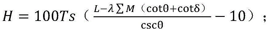
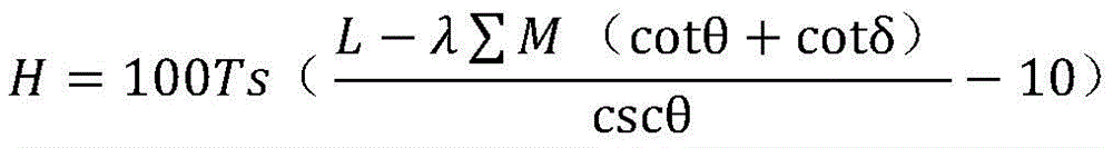
step one: calculating a coal seam stoping safety water head;
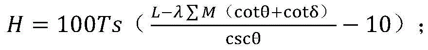
wherein: h, coal seam stoping safety water head, m; ts-critical water break coefficient, MPa/m; l is the width of the coal pillar, m; θ—aquifer tilt angle, °; delta-formation collapse angle, °; lambda-split ratio; m is the coal mining height of a single layer, M;
step two: setting a drainage roadway;
the elevation of the roadway bottom plate of the drainage roadway is 10-20 m below the coal seam stoping safety water head, and the horizontal distance between the drainage roadway and the aquifer is calculated as follows:
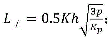
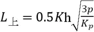
(1) Designing a drainage roadway above the aquifer;

wherein: l (L) Upper part -horizontal safe water separation distance, m, when the drainage lane is above the aquifer; k is a safety coefficient, and 2 to 5 is taken; h, roadway height of a drainage roadway, m; p-actual head pressure, MPa; kp-tensile strength of the water-resistant rock stratum, MPa;
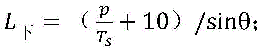
(2) Designing a drainage roadway below the aquifer;
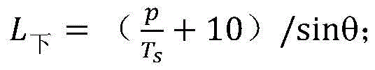
wherein: l (L) Lower part(s) -horizontal safe water separation distance, m, when the drainage lane is above the aquifer;
for aquifers with water-rich property lower than medium, the drainage lane is designed as a drainage lane of an independent lane; for the aquifer with medium water-rich property and above, a drainage roadway with a water sump is designed;
step three: communicating the aquifer with a drainage roadway, and arranging a collecting and dredging hole;
the collecting and dredging holes are of a three-opening structure, one-opening drilling is carried out to the bottom of the surface soil layer and is isolated by a casing pipe, the other-opening directional drilling is carried out to the water-bearing layer and is isolated by the casing pipe, and the three-opening structure comprises 1 main hole and a plurality of branch holes which are bare holes; the lowest point of the final hole of the main hole is set as the elevation of a safe water head, 1-2 branch holes are designed for the aquifer above the erosion reference line, and 3-5 branch holes are designed for the aquifer below the erosion reference line.
Optionally, the horizontal displacement of the branch hole is 300-500 m.
Optionally, when the extension distance of the aquifer is greater than 500m, a plurality of collecting and dredging holes are arranged, and adjacent collecting and dredging holes are communicated and collected to the same drainage roadway at the branch holes.
Optionally, the construction method of the drainage roadway comprises the following steps:
the section of the water drainage tunnel is 4.0-5.0 m wide and 3.0-3.5 m high, and the head-on is stopped at a distance from the aquifer L Upper part Or L Lower part(s) A place;
the drainage roadway is arranged as an independent roadway, a group of drainage holes drilled to the water-bearing layer are constructed at the head-on position of the roadway, the elevation of the final hole is the elevation of the safety water head, and an orifice drainage device is installed;
if a water drainage roadway with a water bin is adopted, a water retaining wall is arranged at the outlet of the roadway, a water drain pipe is arranged on the water retaining wall, and a water drain device is arranged on the water retaining wall.
Optionally, the construction method of the collecting and dredging holes comprises the following steps:
firstly completing construction of two openings, putting the two openings into a sleeve for isolation, constructing a main hole in three openings, then sequentially sidetrack construction branch holes from deep to shallow according to the depth of sidetrack points, and laterally windowing the branch holes by using a whipstock to complete sidetrack;
the drainage roadway is arranged as an independent roadway, and the lowest point of the drainage hole final hole is communicated with a drainage hole in underground construction; the drainage roadway is provided with a water sump, and the drainage collection hole, the final hole and the penetration roadway are communicated with the lowest point of the water sump.
Optionally, the second step specifically includes; for aquifers with medium or lower water enrichment, namely, the unit water inflow quantity q is less than or equal to 1.0L/(s.m), and the drainage roadway is an independent roadway; the water-bearing layer has water-rich property more than medium, namely the unit water inflow quantity q is more than 1.0L/(s.m), and is designed into a drainage channel with a water bin.
A large-descending deep-dredging system for a steeply inclined aquifer is realized by adopting any large-descending deep-dredging method for the steeply inclined aquifer.
Optionally, the method comprises the following steps:
a drainage roadway arranged under the coal seam stoping safety water head for 10-20 m is communicated with a water-bearing layer and a drainage hole arranged in the drainage roadway;
the horizontal distance between the drainage roadway and the aquifer is calculated as follows:
(1) Designing a drainage roadway above the aquifer;
wherein: l (L) Upper part -horizontal safe water separation distance, m, when the drainage lane is above the aquifer; k is a safety coefficient, and 2 to 5 is taken; h, roadway height of a drainage roadway, m; p-actual head pressure, MPa; kp-tensile strength of the water-resistant rock stratum, MPa;
(2) Designing a drainage roadway below the aquifer;
wherein: l (L) Lower part(s) Horizontal safe water-stop distance, m, when the drainage lane is above the aquifer.
Optionally, the coal seam stoping safety water head is calculated by adopting the following formula:

wherein: h, coal seam stoping safety water head, m; ts-critical water break coefficient, MPa/m; l is the width of the coal pillar, m; θ—aquifer tilt angle, °; delta-formation collapse angle, °; lambda-split ratio; m-single layer coal mining height, M.
Optionally, the collecting and distributing hole comprises 1 main hole and a plurality of branch holes; the lowest point of the final hole of the main hole is set as a safe water head elevation, 1-2 branch holes are arranged on the water-bearing layer above the erosion reference line, and 3-5 branch holes are arranged on the water-bearing layer below the erosion reference line.
The invention has the beneficial effects that
(1) The long-distance collecting and dredging holes on the ground are used for replacing a drainage roadway (namely 'replacing the roadway with holes'), water in the water bearing layer at the far end and the high position is conducted to the vicinity of the existing roadway to form a collecting and water collecting gallery, so that the construction length of the drainage roadway is reduced, and the construction period and the construction cost are reduced.
(2) Through arranging the branch hole of a plurality of elevations in the aquifer, increase the range of height that reveals the aquifer, with shallow portion and deep limestone aquifer UNICOM, satisfy the demand of dredging and lowering the decline.
(3) Through the long-distance drilling of the ground multi-branch dredging holes along the limestone aquifer, the probability of exposing the crack is improved, the catchment area is increased, the water discharge amount is increased after the underground drilling is communicated with the ground drilling, the water discharge period is shortened, and the mine production succession is ensured.
(4) The water-bearing layer is revealed by using the ground drilling mode, so that the problems that the underground drilling can not be performed and the underground drilling is unsafe under the high water pressure condition are solved.
Drawings
FIG. 1 is a schematic perspective view of a large-descending water drain with a dredged collecting hole;
FIG. 2 is a diagram of the communication mode between the drainage hole and the underground drainage hole when the drainage roadway is above the aquifer;
FIG. 3 is a diagram of the communication mode between the drainage hole and the underground drainage hole when the drainage roadway is under the aquifer;
FIG. 4 is a diagram showing the communication mode of the collection and evacuation hole group when the steeply inclined aquifer grows longer;
FIG. 5 is a graph of aquifer floor elevation versus unit water inflow;
FIG. 6 is a view showing the way of water discharge communication of a drainage roadway with a water sump;
the reference numerals in the figures are as follows: 1-a surface soil layer, 2-a steeply inclined aquifer, 3-a coal layer, 4-an erosion datum line, 5-a safety water head elevation, 6-one opening, 7-two openings, 8-main holes, 9-gathering and dredging branch holes, 10-drainage lanes and 11-underground drainage holes; 12-water bin and 13-water retaining wall.
Detailed Description
The invention will be described in detail below with reference to the drawings and the detailed description.
Noun interpretation in the present invention:
steeply inclined aquifer: generally refers to aquifers with an inclination greater than 45 °.
Safety water head: refers to the maximum value of the pressure-bearing water head which does not cause water burst of the water-proof top and bottom plates.
Safety head elevation: refers to the elevation at the safety head.
Erosion reference line: and (3) counting and drawing a relation curve of the water inflow quantity q of the hydrogeological exploration drilling unit and the elevation of the water-bearing floor, and calculating the elevation of the water-bearing floor when q is less than or equal to 1.0L/(s.m), wherein the elevation is used as an erosion datum line elevation.
The method for deep-lowering and discharging the steeply inclined aquifer comprises the following steps:
step one: calculating a coal seam stoping safety water head;

wherein: h, coal seam stoping safety water head, m; ts-critical water break coefficient, MPa/m; l is the width of the coal pillar, m; θ—aquifer tilt angle, °; delta-formation collapse angle, °; lambda-split ratio; m is the coal mining height of a single layer, M;
the critical water burst coefficient, the fracture mining and the rock stratum collapse angle ratio are preferably measured values of a mine, and if no measured values exist, experience values similar to those of the mine, a mining area or a coal field are adopted; the dip angle of the aquifer is determined according to geological exploration results.
Step two: setting a drainage roadway;
the elevation of the roadway floor is 10-20 m under the coal seam stoping safety water head, and the horizontal distance between the roadway and the aquifer is calculated as follows:
(1) When the drainage roadway is designed above the aquifer
Wherein: l (L) Upper part -horizontal safe water separation distance, m, when the roadway is above the aquifer; k is a safety coefficient, and 2 to 5 is taken; h, the height of a drainage roadway, m; p-actual head pressure, MPa; kp-tensile strength of the water-resistant rock stratum, MPa;
the water head pressure is calculated according to the elevation of the roadway bottom plate and the elevation of the water level of the water-bearing layer, the value of the safety coefficient takes a larger value in a weak rock stratum or a region with complex structure, and takes a smaller value in a region with medium hardness and above rock stratum or a region with simple structure; the tensile strength of the formation is determined from the test data of the rock sample.
(2) Designing a drainage roadway below the aquifer
Wherein: l (L) Lower part(s) -horizontal safe water separation distance, m, when the roadway is above the aquifer;
for aquifers with medium or lower water enrichment, namely, the unit water inflow quantity q is less than or equal to 1.0L/(s.m), and the drainage roadway is an independent roadway; the water-bearing layer has water-rich property more than medium, namely the unit water inflow quantity q is more than 1.0L/(s.m), and is designed into a drainage channel with a water bin.
Step three: communicating the aquifer with a drainage roadway, and arranging a collecting and dredging hole;
and (3) counting and drawing a relation curve of the water inflow quantity q of the hydrogeological exploration drilling unit and the elevation of the water-bearing floor, and calculating the elevation of the water-bearing floor when q is less than or equal to 1.0L/(s.m), wherein the elevation is used as an erosion datum line elevation.
The collecting and dredging holes are of a three-opening structure, one-opening drilling is carried out to the bottom of the surface soil layer and is isolated by the lower sleeve, the other-opening directional drilling is carried out to the water-bearing layer and is isolated by the lower sleeve, and the three-opening structure comprises 1 main hole and a plurality of branch holes which are bare holes.
The lowest point of the final hole of the main hole is set as the elevation of the safety water head, and the branch holes are separated from the main hole by different depths. The aquifer above the erosion reference line is designed with 1-2 branch holes, and the aquifer below the erosion reference plane is designed with 3-5 branch holes. In order to control the offset of the drilled holes, the horizontal displacement of the branch holes is designed to be 300-500 m. For the longer extension distance of the aquifer, a plurality of hole sets can be arranged for communication.
Further comprises:
step four: construction drainage roadway
The width of the tunnel section is 4.0-5.0 m, and the height is 3.0-3.5 m. Tunneling over aquifers, with the head-on stop at a distance L from the aquifer Lower part(s) Where the head-on is stopped at a distance L from the aquifer and tunneled under the aquifer Lower part(s) Where it is located.
The drainage roadway is set as an independent roadway, a group of drainage holes drilled to a water-bearing layer are constructed at the head-on position of the roadway, the length of a water-stopping sleeve is determined according to water pressure, the water-stopping sleeve is 20-100 m when the water pressure is greater than 3MPa, the water-stopping sleeve is 5-20 m when the water pressure is less than 3MPa, the elevation of a final hole is the elevation of a safe water head, and an orifice drainage device is arranged at a sleeve opening after the hole is completed, and comprises a drainage control valve and a pressure gauge.
If a water drainage roadway with a water bin is adopted, a water retaining wall is arranged at the outlet of the roadway, a water drain pipe is arranged on the water retaining wall, and a water drain device is arranged on the water retaining wall.
Step five: the construction collecting and dredging hole is communicated with the underground
Firstly, constructing an opening to 5-10 m below a surface soil layer, putting a sleeve into the opening, and cementing the well; and then constructing a second-time-opening to a steeply inclined aquifer, putting a sleeve into the cement and cementing the cement. And thirdly, firstly constructing a main hole to a designed position, communicating with a downhole water draining hole or a water sump, and then completing branch holes by using a whipstock to laterally open a window and laterally drill according to the depth of a laterally drilled point from deep to shallow.
The drainage roadway is arranged as an independent roadway, the lowest point of the drainage hole end hole is communicated with a drainage drill hole of underground construction, the communication mode can be conducted by adopting strong magnetism, namely, strong magnetism is placed in the drainage hole end hole, and the main hole drills into the drainage hole position according to a strong magnetism signal to realize communication.
The drainage roadway is provided with a water sump, and the drainage collection hole, the final hole and the penetration roadway are communicated with the lowest point of the water sump.
Step six: water discharge
And opening a valve on a downhole water drain hole or a water drain pipe, observing the water discharge amount and the water level of the water-bearing layer, and if the water discharge amount is smaller or the water level drops slowly, increasing the water permeability of the water-bearing layer in a fracturing or pickling mode so as to meet the requirement of quick drainage.
Step seven: collecting and dredging hole sealing
And (3) lowering the water stop plug to the bottom of the two-way sleeve, and injecting cement slurry into the drill rod to seal the upper drilling hole of the water stop plug. The three open sections remain communicated with the underground to continue draining water. The water level of the aquifer can be calculated according to the reading of the pressure gauge of the orifice of the water discharging hole in the water discharging process so as to determine whether the water is dredged down to the safe water head.
The large-descending deep-dredging system of the steeply inclined aquifer is realized by adopting any large-descending deep-dredging method of the steeply inclined aquifer.
Comprising the following steps:
a drainage roadway arranged under the coal seam stoping safety water head for 10-20 m is communicated with a water-bearing layer and a drainage hole arranged in the drainage roadway;
the horizontal distance between the drainage lane and the aquifer is calculated as follows:
(1) Designing a drainage roadway above the aquifer;
wherein: l (L) Upper part -horizontal safe water separation distance, m, when the drainage lane is above the aquifer; k is a safety coefficient, and 2 to 5 is taken; h, roadway height of a drainage roadway, m; p-actual head pressure, MPa; kp-tensile strength of the water-resistant rock stratum, MPa;
(2) Designing a drainage roadway below the aquifer;
wherein: l (L) Lower part(s) Horizontal safe water-stop distance, m, when the drainage lane is above the aquifer. For aquifers with medium or lower water enrichment, namely, the unit water inflow quantity q is less than or equal to 1.0L/(s.m), and the drainage roadway is an independent roadway; the water-bearing layer has water-rich property more than medium, namely the unit water inflow quantity q is more than 1.0L/(s.m), and is designed into a drainage channel with a water bin.
The coal seam stoping safety water head is calculated by adopting the following formula:
wherein: h, coal seam stoping safety water head, m; ts-critical water break coefficient, MPa/m; l is the width of the coal pillar, m; θ—aquifer tilt angle, °; delta-formation collapse angle, °; lambda-split ratio; m-single layer coal mining height, M.
The collecting and distributing holes comprise 1 main hole and a plurality of branch holes; the lowest point of the final hole of the main hole is set as a safe water head elevation, 1-2 branch holes are arranged on the water-bearing layer above the erosion reference line, and 3-5 branch holes are arranged on the water-bearing layer below the erosion reference line. When the extension distance of the aquifer is more than 500m, a plurality of collecting and dredging holes are arranged, and the adjacent collecting and dredging holes are communicated and collected to the same drainage roadway at the branch holes.
The technical scheme of the present invention will be described in detail with reference to specific examples.
Embodiment one:
huaibei coal field certain ore is in F 25 Under the action of the reverse-covering fault, the 1-4 ash (1-6 ash locally) aquifer of the coal bed floor Taiyuan group is thrust-covered on the side of the main coal bed, and the top of the aquifer is contacted with the surface soil layer. The dip angle of the limestone aquifer is 50-60 degrees, the extension length is 4932-5175 m, the thickness is 42-68 m, the unit water inflow quantity q= 0.00512-0.19 lL/(s.m), and the water enrichment is weak-medium. The elevation of the bottom plate of the main coal mining layer is minus 390 to minus 800m, the elevation of the original water level of the limestone aquifer of the Taiyuan group is minus 3.59 to 1.20m, the top plate of the coal seam bears 3.8 to 8MPa of water pressure, and the threat to safety exploitation is great.
In order to eliminate the threat of limestone water damage on the roof of the main coal mining layer, the mine organization implements the too-ash aquifer dredging and descending engineering of 'drainage lane + drainage hole', the drainage lane of 510m is completed in an accumulated way, 84 dredging and descending drilling footage 15304m is constructed, only 23 holes are used for water yielding, and the drainage amount is 51m 3 And/h. The water level of the too gray aquifer in the exploitation range is reduced to-491-640 m. However, the underground drainage roadway and drainage borehole drainage scheme has the problems of slow construction progress of the underground roadway, low water outlet probability of the underground drainage borehole, small water discharge amount and the like, and too much ash water level is not reduced below a safety water head (-700 m) required by coal seam exploitation, so that the mining area succession work cannot be satisfied.
In order to increase the water quantity of the too-ash drainage, the drainage range is enlarged so as to meet the safety stope of the working face. By adopting the technology, the far end of the roadway and the too-gray water-bearing layer at the shallow part are conducted to the vicinity of the existing roadway to form a water collecting gallery, and then the underground water drainage drilling hole is connected with the water collecting hole, so that the too-gray water-bearing layer of the pushing body is greatly reduced in depth and dredged. The specific implementation mode is as follows:
step one: and calculating a safety water head meeting the coal seam stoping.
Wherein: h is a safety water head, m; ts-critical water break coefficient, MPa/m; l is the width of the coal pillar, m; θ—aquifer tilt angle, °; delta-formation collapse angle, °; lambda-split ratio; m-single layer coal mining height, M.
In the example, ts is 0.1MPa/m, L is 50m, θ is 54 degrees, δ is 73 degrees, λ is 12, M is 3m, and H is 99.35m, namely the elevation of the safety water head is about-700 m.
Step two: designing the position of a drainage roadway
The elevation of the roadway bottom plate is 20m below the coal seam stoping safety water head, namely-720 m, and a drainage roadway of a mine south wing is arranged above an aquifer as shown in figures 1 and 2, and comprises a topsoil layer 1, a steeply inclined aquifer 2, a coal seam 3, an erosion datum line 4, a safety water head elevation 5, a primary opening 6, a secondary opening 7, a primary hole 8, a branch hole 9, a drainage roadway 10 and a downhole drainage hole 11; the horizontal distance from the aquifer is calculated as follows:
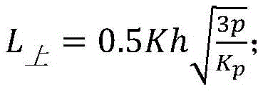
wherein: l (L) Upper part -horizontal safe water separation distance, m, when the roadway is above the aquifer; k is a safety coefficient, and 2 to 5 is taken; h, the height of a drainage roadway, m; p-head pressure, MPa; kp-tensile strength of the water-resistant rock stratum, MPa.
In this example, K is 3, h is 3m, p is 8MPa, kp is 1.5MPa, and L is calculated Upper part 18m.
The drainage lane of the north wing of the mine is above the aquifer as in fig. 3, and the horizontal distance from the aquifer is calculated as follows:

wherein: l (L) Lower part(s) Horizontal safe riser distance, m, when the roadway is above the aquifer.
In this example, p is 8MPa, ts is 0.1MPa/m, θ is 54 degrees, and L is calculated Lower part(s) 111m.
Step three: design collection and drainage hole
The relation curve of the water inflow q of the hydrogeological exploration drilling unit and the elevation of the water-bearing floor is shown as figure 5, and the elevation of the water-bearing floor is-400 m when q is less than or equal to 1.0L/(s.m) and is calculated as the elevation of the erosion datum line.
The collecting and dredging holes are of a three-opening structure, one-opening drilling is carried out to the bottom of the surface soil layer and is isolated by the lower sleeve, the other-opening directional drilling is carried out to the limestone aquifer and is isolated by the lower sleeve, and the three-opening structure comprises 1 main hole and 5 branch holes which are bare holes.
The lowest point of the final hole of the main hole is set to be the safety water head elevation-700 m. The aquifer above the erosion reference line is provided with 1 horizontal branch hole, the aquifer below the erosion reference plane is provided with 3 horizontal branch holes, and the lower part of the main hole is provided with 1 large-inclination branch hole. To control the offset of the drilled holes, the horizontal displacement of the branch holes was designed to be 400m. In the north wing of the mine, a plurality of collecting and dredging hole groups are arranged for communication in the mode of fig. 4 due to longer extension distance of the limestone aquifer.
Step four: construction drainage roadway
The section of the drainage tunnel is 4.0m wide and 3.0m high.
The drainage roadway is set as an independent roadway, 2 drainage drill holes are constructed at the head-on position of the roadway, the drill holes are drilled to the limestone aquifer, the elevation of the final hole is the elevation of a safe water head to 700m, and an orifice drainage device is installed.
As shown in fig. 6, if a drainage roadway with a water bin 12 is adopted, a water retaining wall 13 is arranged at the outlet of the roadway, and a water drain pipe and a water drain device are arranged on the water retaining wall 13.
Step five: the construction collecting and dredging hole is communicated with the underground
Firstly drilling a hole with a diameter of 311mm to the bottom of a surface soil layer, putting a sleeve with a diameter of phi 244.5mm multiplied by 8.94mm for isolation, secondly drilling a hole with a diameter of 215.9mm to a limestone water-bearing layer, putting a sleeve with a diameter of phi 177.8mm multiplied by 8.05mm for isolation, thirdly, firstly constructing a main hole with a diameter of 152mm, then sequentially sidewise drilling construction horizontal branch holes from deep to shallow according to the depth of a sidewise drilling point, wherein the elevations of the branch holes are sequentially-600 m, -500m, -400m and-250 m from bottom to top, drilling a large-inclination branch hole from the lower part of the main hole to-700 m from the opening of the sleeve, laterally windowing the branch holes by using a whipstock to finish sidewise extraction, and recovering the whipstock to construct the next branch hole after the completion of one branch hole.
The elevation of the lowest point of the main hole and the final hole of the large-inclination branch hole, namely 700m, is communicated with a drainage drill hole for drainage roadway construction.
Step six: water discharge
The valve on the underground water drain hole or the water drain pipe is opened, the water discharge amount and the water level of the aquifer are observed, the water permeability of the aquifer is increased by adopting an acid washing mode, and the water discharge amount is controlled to be 51m initially 3 Increase/h to 70.5m 3 And/h. And according to the ground long observation hole monitoring data, the water level of the dredging and descending center is reduced to-720 m, and the water level of the limestone aquifer is reduced to below the safety water head, so that the requirement of safety stoping is met.
Step seven: collecting and dredging hole sealing
And (3) lowering the water stop plug to the bottom of the two-way sleeve, and injecting cement slurry into the drill rod to seal the upper drilling hole of the water stop plug. The three open sections remain communicated with the underground to continue draining water.
The invention successfully reveals the water storage space of the steeply inclined limestone aquifer by utilizing the ground collecting and dredging holes, expands the dredging and descending range, can replace an underground drainage roadway, reduces the engineering quantity of 1400m for the drainage roadway, and reduces the drilling engineering quantity of 12000m for the underground drainage hole. The construction cost of the drainage roadway is 2.7 ten thousand yuan/m, the construction cost of the drainage hole is 730 yuan/m, the construction cost of the roadway is saved by about 3780 ten thousand yuan, the detection cost of the drainage hole is 876 ten thousand yuan, the total cost of the drainage hole is 4656 ten thousand yuan, the engineering cost of collecting and dredging holes is deducted, and the economic benefit is created by about 4076 ten thousand yuan. The invention proves that the invention is economically feasible for large-scale and large-drop deep drainage of the steeply inclined aquifer.
The above description is only of the preferred embodiments of the present invention, and is not intended to limit the present invention in any way, and any simple modification, equivalent variation and modification made to the above embodiments according to the technical principles of the present invention still fall within the scope of the technical solutions of the present invention.
Claims (7)
1. A method for deep-drawing a steeply dipping aquifer comprising:
step one: calculating a coal seam stoping safety water head;

wherein: h, coal seam stoping safety water head, m; ts-critical water break coefficient, MPa/m; l is the width of the coal pillar, m; θ—aquifer tilt angle, °; delta-formation collapse angle, °; lambda-split ratio; m is the coal mining height of a single layer, M;
step two: setting a drainage roadway;
the elevation of the roadway bottom plate of the drainage roadway is 10-20 m below the coal seam stoping safety water head, and the horizontal distance between the drainage roadway and the aquifer is calculated as follows:
(1) Designing a drainage roadway above the aquifer;
wherein:L upper part -horizontal safe water separation distance, m, when the drainage lane is above the aquifer;K2-5 safety factors;h-the roadway height of the drainage roadway, m;p-actual head pressure, MPa;Kp-tensile strength of the water-barrier layer, MPa;
(2) Designing a drainage roadway below the aquifer;

wherein:L lower part(s) -horizontal safe water separation distance, m, when the drainage lane is above the aquifer;
for aquifers with water-rich property lower than medium, the drainage lane is designed as a drainage lane of an independent lane; for the aquifer with medium water-rich property and above, a drainage roadway with a water sump is designed;
step three: communicating the aquifer with a drainage roadway, and arranging a collecting and dredging hole;
the collecting and dredging holes are of a three-opening structure, one-opening drilling is carried out to the bottom of the surface soil layer and is isolated by a casing pipe, the other-opening directional drilling is carried out to the water-bearing layer and is isolated by the casing pipe, and the three-opening structure comprises 1 main hole and a plurality of branch holes which are bare holes; the lowest point of the final hole of the main hole is set to be a safe water head elevation, 1-2 branch holes are designed for the water-bearing layer above the erosion reference line, and 3-5 branch holes are designed for the water-bearing layer below the erosion reference line.
2. The method for deep-drawing and discharging a steeply inclined aquifer according to claim 1, wherein the horizontal displacement of the branch hole is 300-500 m.
3. The method for deep drainage of a steeply inclined aquifer according to claim 1 or 2, wherein when the extension distance of the aquifer is more than 500m, a plurality of drainage collecting holes are arranged, and adjacent drainage collecting holes are communicated and collected to the same drainage roadway at branch holes.
4. The method for deep-drawing and discharging the steeply inclined aquifer according to claim 1 or 2, wherein the construction method for the drainage roadway comprises the following steps:
the section of the water drainage tunnel is 4.0-5.0 m wide and 3.0-3.5 m high, and the head-on is stopped at a distance from the aquiferL Upper part Or (b)L Lower part(s) A place;
the drainage roadway is arranged as an independent roadway, a group of drainage holes drilled to the water-bearing layer are constructed at the head-on position of the roadway, the elevation of the final hole is the elevation of the safety water head, and an orifice drainage device is installed;
if a water drainage roadway with a water bin is adopted, a water retaining wall is arranged at the outlet of the roadway, a water drain pipe is arranged on the water retaining wall, and a water drain device is arranged on the water retaining wall.
5. The method for deep-lowering and dredging the steeply inclined aquifer according to claim 1 or 2, wherein the method for constructing the dredging holes comprises the following steps:
firstly completing construction of two openings, putting the two openings into a sleeve for isolation, constructing a main hole in three openings, then sequentially sidetrack construction branch holes from deep to shallow according to the depth of sidetrack points, and laterally windowing the branch holes by using a whipstock to complete sidetrack;
the drainage roadway is arranged as an independent roadway, and the lowest point of the drainage hole final hole is communicated with a drainage hole in underground construction; the drainage roadway is provided with a water sump, and the drainage collection hole, the final hole and the penetration roadway are communicated with the lowest point of the water sump.
6. The method for deep-drawing and discharging a steeply inclined aquifer according to claim 1 or 2, wherein the second step comprises the following steps; for aquifers with medium or lower water enrichment, namely, the unit water inflow quantity q is less than or equal to 1.0L/(s.m), and the drainage roadway is an independent roadway; the water-bearing layer has water-rich property more than medium, namely the unit water inflow quantity q is more than 1.0L/(s.m), and is designed into a drainage channel with a water bin.
7. A large-lowering deep-dredging system for a steeply inclined aquifer, which is characterized in that the system is realized by adopting the large-lowering deep-dredging method for the steeply inclined aquifer according to any one of claims 1-6.
Priority Applications (1)
| Application Number | Priority Date | Filing Date | Title |
|---|---|---|---|
| CN202210986884.7A CN115450693B (en) | 2022-08-17 | 2022-08-17 | Large-drop deep-discharging method and system for steeply inclined aquifer |
Applications Claiming Priority (1)
| Application Number | Priority Date | Filing Date | Title |
|---|---|---|---|
| CN202210986884.7A CN115450693B (en) | 2022-08-17 | 2022-08-17 | Large-drop deep-discharging method and system for steeply inclined aquifer |
Publications (2)
| Publication Number | Publication Date |
|---|---|
| CN115450693A CN115450693A (en) | 2022-12-09 |
| CN115450693B true CN115450693B (en) | 2023-07-14 |
Family
ID=84299741
Family Applications (1)
| Application Number | Title | Priority Date | Filing Date |
|---|---|---|---|
| CN202210986884.7A Active CN115450693B (en) | 2022-08-17 | 2022-08-17 | Large-drop deep-discharging method and system for steeply inclined aquifer |
Country Status (1)
| Country | Link |
|---|---|
| CN (1) | CN115450693B (en) |
Citations (12)
| Publication number | Priority date | Publication date | Assignee | Title |
|---|---|---|---|---|
| SU1352067A1 (en) * | 1985-09-03 | 1987-11-15 | Специализированное производственное геологическое объединение по тампонажным и геологоразведочным работам "Спецтампонажгеология" | Method of isolating vertical mine workings from subsoil water inflow |
| SU1434135A1 (en) * | 1987-01-05 | 1988-10-30 | Всесоюзный Научно-Исследовательский И Проектно-Конструкторский Институт По Осушению Месторождений Полезных Ископаемых,Специальным Горным Работам,Рудничной Геологии И Маркшейдерскому Делу | Method of shaft drainage |
| US4986696A (en) * | 1987-06-15 | 1991-01-22 | Veszpremi Szenbanyak | Method of dewatering a subterranean space, especially a mine |
| US6280000B1 (en) * | 1998-11-20 | 2001-08-28 | Joseph A. Zupanick | Method for production of gas from a coal seam using intersecting well bores |
| CN101050709A (en) * | 2006-04-03 | 2007-10-10 | 郭国政 | High water pressure releasing and blocking mining method for mining area |
| CN108518182A (en) * | 2018-04-16 | 2018-09-11 | 中煤科工集团西安研究院有限公司 | Method and device is put in the advanced region water body spy of the dendritic directional drilling of top plate multi-aquifer |
| CN109611146A (en) * | 2018-11-29 | 2019-04-12 | 山东科技大学 | A kind of abscission water drainage grouting method |
| CN111140279A (en) * | 2020-03-09 | 2020-05-12 | 西安科技大学 | Method for preventing and treating old empty water on thick coal seam under condition of repeated mining caused by small kiln damage to layering |
| CN112502774A (en) * | 2020-09-23 | 2021-03-16 | 淮北矿业股份有限公司 | Method for dredging limestone water by utilizing ground directional water collecting holes |
| CN112855260A (en) * | 2021-02-03 | 2021-05-28 | 中煤科工集团西安研究院有限公司 | Method for quickly dredging and descending all areas of underground curtain after closure |
| CN113027522A (en) * | 2021-02-03 | 2021-06-25 | 淮北矿业股份有限公司 | Coal mine drainage same-layer recharging method |
| CN113236359A (en) * | 2021-05-28 | 2021-08-10 | 中煤科工集团西安研究院有限公司 | Separation layer water drainage method, separation layer water drainage roadway system and construction method |
-
2022
- 2022-08-17 CN CN202210986884.7A patent/CN115450693B/en active Active
Patent Citations (12)
| Publication number | Priority date | Publication date | Assignee | Title |
|---|---|---|---|---|
| SU1352067A1 (en) * | 1985-09-03 | 1987-11-15 | Специализированное производственное геологическое объединение по тампонажным и геологоразведочным работам "Спецтампонажгеология" | Method of isolating vertical mine workings from subsoil water inflow |
| SU1434135A1 (en) * | 1987-01-05 | 1988-10-30 | Всесоюзный Научно-Исследовательский И Проектно-Конструкторский Институт По Осушению Месторождений Полезных Ископаемых,Специальным Горным Работам,Рудничной Геологии И Маркшейдерскому Делу | Method of shaft drainage |
| US4986696A (en) * | 1987-06-15 | 1991-01-22 | Veszpremi Szenbanyak | Method of dewatering a subterranean space, especially a mine |
| US6280000B1 (en) * | 1998-11-20 | 2001-08-28 | Joseph A. Zupanick | Method for production of gas from a coal seam using intersecting well bores |
| CN101050709A (en) * | 2006-04-03 | 2007-10-10 | 郭国政 | High water pressure releasing and blocking mining method for mining area |
| CN108518182A (en) * | 2018-04-16 | 2018-09-11 | 中煤科工集团西安研究院有限公司 | Method and device is put in the advanced region water body spy of the dendritic directional drilling of top plate multi-aquifer |
| CN109611146A (en) * | 2018-11-29 | 2019-04-12 | 山东科技大学 | A kind of abscission water drainage grouting method |
| CN111140279A (en) * | 2020-03-09 | 2020-05-12 | 西安科技大学 | Method for preventing and treating old empty water on thick coal seam under condition of repeated mining caused by small kiln damage to layering |
| CN112502774A (en) * | 2020-09-23 | 2021-03-16 | 淮北矿业股份有限公司 | Method for dredging limestone water by utilizing ground directional water collecting holes |
| CN112855260A (en) * | 2021-02-03 | 2021-05-28 | 中煤科工集团西安研究院有限公司 | Method for quickly dredging and descending all areas of underground curtain after closure |
| CN113027522A (en) * | 2021-02-03 | 2021-06-25 | 淮北矿业股份有限公司 | Coal mine drainage same-layer recharging method |
| CN113236359A (en) * | 2021-05-28 | 2021-08-10 | 中煤科工集团西安研究院有限公司 | Separation layer water drainage method, separation layer water drainage roadway system and construction method |
Non-Patent Citations (4)
| Title |
|---|
| 二_1煤东翼疏水巷突水机理分析;程战超等;煤矿现代化(第06期);第31-33页 * |
| 大采深煤层中探放老空积水钻孔施工工艺;周玉华;煤矿现代化(第04期);第13-14页 * |
| 庚三采区防治水工程设计;马莉萍等;水力采煤与管道运输(第03期);第75-76、92页 * |
| 煤矿老空区定向探查钻孔的施工应用;李浩;能源与环保;第43卷(第2期);第50-54页 * |
Also Published As
| Publication number | Publication date |
|---|---|
| CN115450693A (en) | 2022-12-09 |
Similar Documents
| Publication | Publication Date | Title |
|---|---|---|
| CN111140279B (en) | Method for preventing and treating old empty water on thick coal seam under condition of repeated mining caused by small kiln damage to layering | |
| CN111535791B (en) | Efficient gas extraction method for broken soft low-permeability coal seam well upper and lower combined fracturing area | |
| CN103742145B (en) | Colliery rich water abnormal area water prevention method | |
| CN105804754B (en) | A kind of coal seam is Main aquifer pitshaft method for uncovering coal | |
| CN110043312B (en) | Control method for grouting filling ground surface settlement range | |
| CN111878079B (en) | A gas control method for soft outburst coal seam in large mining length working face in underground coal mine | |
| CN106869966B (en) | A kind of method for blocking of absciss layer water supply source | |
| CN110656939B (en) | Large-stage efficient mining method for steeply inclined medium-thickness ore body meeting water argillization surrounding rock | |
| CN111075478A (en) | Pre-grouting reinforcement process for ground construction of broken belt of excavation working face structure | |
| CN114439428B (en) | Enhanced extraction method for coal bed gas horizontal well of coal group under goaf group | |
| CN103867229A (en) | Coal mine large-mining-depth and next-group coal exploitation water control comprehensive treatment method | |
| CN104975868A (en) | Top plate high-position boring large-diameter long-drill-hole gas extraction method based on directional drilling | |
| CN110778317A (en) | Construction method for ground grouting filling drilling structure in caving zone in mining process | |
| CN113006111A (en) | Method for plugging flow of top and bottom boundary fault zone of curtain | |
| CN112855260A (en) | Method for quickly dredging and descending all areas of underground curtain after closure | |
| CN113482600B (en) | A one-hole dual-purpose method for coalfield geological exploration and mining rock formation movement monitoring | |
| CN115450693B (en) | Large-drop deep-discharging method and system for steeply inclined aquifer | |
| CN119041895B (en) | Directional drilling measurement technology-based water guide fracture zone detection method | |
| CN114109492A (en) | Construction method of coal mine double-layer underground reservoir | |
| CN113464203A (en) | Ground-underground combined exploration and treatment method for geological anomalous body of mine | |
| CN116084888B (en) | Advanced pre-extraction method based on enhanced extraction of gas from horizontal wells with full coverage of working face | |
| CN113586134B (en) | Method for controlling gas by hole-instead-of-lane combined drainage on coal seam working face | |
| CN117703398A (en) | Construction method for large-section rectangular jacking pipe in shallow soil-covered water-rich composite stratum | |
| CN116877026A (en) | Grouting method for bad drilling | |
| CN116557039A (en) | Collaborative Disaster Control Pore Structure and Collaborative Disaster Control Method in Mine |
Legal Events
| Date | Code | Title | Description |
|---|---|---|---|
| PB01 | Publication | ||
| PB01 | Publication | ||
| SE01 | Entry into force of request for substantive examination | ||
| SE01 | Entry into force of request for substantive examination | ||
| GR01 | Patent grant | ||
| GR01 | Patent grant |