CN115440641A - Dodecagonal transfer chamber and processing system with dodecagonal transfer chamber - Google Patents
Dodecagonal transfer chamber and processing system with dodecagonal transfer chamber Download PDFInfo
- Publication number
- CN115440641A CN115440641A CN202211014290.6A CN202211014290A CN115440641A CN 115440641 A CN115440641 A CN 115440641A CN 202211014290 A CN202211014290 A CN 202211014290A CN 115440641 A CN115440641 A CN 115440641A
- Authority
- CN
- China
- Prior art keywords
- chamber
- substrate
- transfer
- processing
- load lock
- Prior art date
- Legal status (The legal status is an assumption and is not a legal conclusion. Google has not performed a legal analysis and makes no representation as to the accuracy of the status listed.)
- Pending
Links
Images


Classifications
-
- H10P72/0454—
-
- B—PERFORMING OPERATIONS; TRANSPORTING
- B25—HAND TOOLS; PORTABLE POWER-DRIVEN TOOLS; MANIPULATORS
- B25J—MANIPULATORS; CHAMBERS PROVIDED WITH MANIPULATION DEVICES
- B25J15/00—Gripping heads and other end effectors
-
- C—CHEMISTRY; METALLURGY
- C23—COATING METALLIC MATERIAL; COATING MATERIAL WITH METALLIC MATERIAL; CHEMICAL SURFACE TREATMENT; DIFFUSION TREATMENT OF METALLIC MATERIAL; COATING BY VACUUM EVAPORATION, BY SPUTTERING, BY ION IMPLANTATION OR BY CHEMICAL VAPOUR DEPOSITION, IN GENERAL; INHIBITING CORROSION OF METALLIC MATERIAL OR INCRUSTATION IN GENERAL
- C23C—COATING METALLIC MATERIAL; COATING MATERIAL WITH METALLIC MATERIAL; SURFACE TREATMENT OF METALLIC MATERIAL BY DIFFUSION INTO THE SURFACE, BY CHEMICAL CONVERSION OR SUBSTITUTION; COATING BY VACUUM EVAPORATION, BY SPUTTERING, BY ION IMPLANTATION OR BY CHEMICAL VAPOUR DEPOSITION, IN GENERAL
- C23C14/00—Coating by vacuum evaporation, by sputtering or by ion implantation of the coating forming material
- C23C14/22—Coating by vacuum evaporation, by sputtering or by ion implantation of the coating forming material characterised by the process of coating
- C23C14/56—Apparatus specially adapted for continuous coating; Arrangements for maintaining the vacuum, e.g. vacuum locks
- C23C14/564—Means for minimising impurities in the coating chamber such as dust, moisture, residual gases
- C23C14/566—Means for minimising impurities in the coating chamber such as dust, moisture, residual gases using a load-lock chamber
-
- C—CHEMISTRY; METALLURGY
- C23—COATING METALLIC MATERIAL; COATING MATERIAL WITH METALLIC MATERIAL; CHEMICAL SURFACE TREATMENT; DIFFUSION TREATMENT OF METALLIC MATERIAL; COATING BY VACUUM EVAPORATION, BY SPUTTERING, BY ION IMPLANTATION OR BY CHEMICAL VAPOUR DEPOSITION, IN GENERAL; INHIBITING CORROSION OF METALLIC MATERIAL OR INCRUSTATION IN GENERAL
- C23C—COATING METALLIC MATERIAL; COATING MATERIAL WITH METALLIC MATERIAL; SURFACE TREATMENT OF METALLIC MATERIAL BY DIFFUSION INTO THE SURFACE, BY CHEMICAL CONVERSION OR SUBSTITUTION; COATING BY VACUUM EVAPORATION, BY SPUTTERING, BY ION IMPLANTATION OR BY CHEMICAL VAPOUR DEPOSITION, IN GENERAL
- C23C16/00—Chemical coating by decomposition of gaseous compounds, without leaving reaction products of surface material in the coating, i.e. chemical vapour deposition [CVD] processes
- C23C16/04—Coating on selected surface areas, e.g. using masks
- C23C16/042—Coating on selected surface areas, e.g. using masks using masks
-
- C—CHEMISTRY; METALLURGY
- C23—COATING METALLIC MATERIAL; COATING MATERIAL WITH METALLIC MATERIAL; CHEMICAL SURFACE TREATMENT; DIFFUSION TREATMENT OF METALLIC MATERIAL; COATING BY VACUUM EVAPORATION, BY SPUTTERING, BY ION IMPLANTATION OR BY CHEMICAL VAPOUR DEPOSITION, IN GENERAL; INHIBITING CORROSION OF METALLIC MATERIAL OR INCRUSTATION IN GENERAL
- C23C—COATING METALLIC MATERIAL; COATING MATERIAL WITH METALLIC MATERIAL; SURFACE TREATMENT OF METALLIC MATERIAL BY DIFFUSION INTO THE SURFACE, BY CHEMICAL CONVERSION OR SUBSTITUTION; COATING BY VACUUM EVAPORATION, BY SPUTTERING, BY ION IMPLANTATION OR BY CHEMICAL VAPOUR DEPOSITION, IN GENERAL
- C23C16/00—Chemical coating by decomposition of gaseous compounds, without leaving reaction products of surface material in the coating, i.e. chemical vapour deposition [CVD] processes
- C23C16/22—Chemical coating by decomposition of gaseous compounds, without leaving reaction products of surface material in the coating, i.e. chemical vapour deposition [CVD] processes characterised by the deposition of inorganic material, other than metallic material
- C23C16/30—Deposition of compounds, mixtures or solid solutions, e.g. borides, carbides, nitrides
- C23C16/308—Oxynitrides
-
- C—CHEMISTRY; METALLURGY
- C23—COATING METALLIC MATERIAL; COATING MATERIAL WITH METALLIC MATERIAL; CHEMICAL SURFACE TREATMENT; DIFFUSION TREATMENT OF METALLIC MATERIAL; COATING BY VACUUM EVAPORATION, BY SPUTTERING, BY ION IMPLANTATION OR BY CHEMICAL VAPOUR DEPOSITION, IN GENERAL; INHIBITING CORROSION OF METALLIC MATERIAL OR INCRUSTATION IN GENERAL
- C23C—COATING METALLIC MATERIAL; COATING MATERIAL WITH METALLIC MATERIAL; SURFACE TREATMENT OF METALLIC MATERIAL BY DIFFUSION INTO THE SURFACE, BY CHEMICAL CONVERSION OR SUBSTITUTION; COATING BY VACUUM EVAPORATION, BY SPUTTERING, BY ION IMPLANTATION OR BY CHEMICAL VAPOUR DEPOSITION, IN GENERAL
- C23C16/00—Chemical coating by decomposition of gaseous compounds, without leaving reaction products of surface material in the coating, i.e. chemical vapour deposition [CVD] processes
- C23C16/22—Chemical coating by decomposition of gaseous compounds, without leaving reaction products of surface material in the coating, i.e. chemical vapour deposition [CVD] processes characterised by the deposition of inorganic material, other than metallic material
- C23C16/30—Deposition of compounds, mixtures or solid solutions, e.g. borides, carbides, nitrides
- C23C16/34—Nitrides
- C23C16/345—Silicon nitride
-
- C—CHEMISTRY; METALLURGY
- C23—COATING METALLIC MATERIAL; COATING MATERIAL WITH METALLIC MATERIAL; CHEMICAL SURFACE TREATMENT; DIFFUSION TREATMENT OF METALLIC MATERIAL; COATING BY VACUUM EVAPORATION, BY SPUTTERING, BY ION IMPLANTATION OR BY CHEMICAL VAPOUR DEPOSITION, IN GENERAL; INHIBITING CORROSION OF METALLIC MATERIAL OR INCRUSTATION IN GENERAL
- C23C—COATING METALLIC MATERIAL; COATING MATERIAL WITH METALLIC MATERIAL; SURFACE TREATMENT OF METALLIC MATERIAL BY DIFFUSION INTO THE SURFACE, BY CHEMICAL CONVERSION OR SUBSTITUTION; COATING BY VACUUM EVAPORATION, BY SPUTTERING, BY ION IMPLANTATION OR BY CHEMICAL VAPOUR DEPOSITION, IN GENERAL
- C23C16/00—Chemical coating by decomposition of gaseous compounds, without leaving reaction products of surface material in the coating, i.e. chemical vapour deposition [CVD] processes
- C23C16/22—Chemical coating by decomposition of gaseous compounds, without leaving reaction products of surface material in the coating, i.e. chemical vapour deposition [CVD] processes characterised by the deposition of inorganic material, other than metallic material
- C23C16/30—Deposition of compounds, mixtures or solid solutions, e.g. borides, carbides, nitrides
- C23C16/40—Oxides
- C23C16/401—Oxides containing silicon
- C23C16/402—Silicon dioxide
-
- C—CHEMISTRY; METALLURGY
- C23—COATING METALLIC MATERIAL; COATING MATERIAL WITH METALLIC MATERIAL; CHEMICAL SURFACE TREATMENT; DIFFUSION TREATMENT OF METALLIC MATERIAL; COATING BY VACUUM EVAPORATION, BY SPUTTERING, BY ION IMPLANTATION OR BY CHEMICAL VAPOUR DEPOSITION, IN GENERAL; INHIBITING CORROSION OF METALLIC MATERIAL OR INCRUSTATION IN GENERAL
- C23C—COATING METALLIC MATERIAL; COATING MATERIAL WITH METALLIC MATERIAL; SURFACE TREATMENT OF METALLIC MATERIAL BY DIFFUSION INTO THE SURFACE, BY CHEMICAL CONVERSION OR SUBSTITUTION; COATING BY VACUUM EVAPORATION, BY SPUTTERING, BY ION IMPLANTATION OR BY CHEMICAL VAPOUR DEPOSITION, IN GENERAL
- C23C16/00—Chemical coating by decomposition of gaseous compounds, without leaving reaction products of surface material in the coating, i.e. chemical vapour deposition [CVD] processes
- C23C16/44—Chemical coating by decomposition of gaseous compounds, without leaving reaction products of surface material in the coating, i.e. chemical vapour deposition [CVD] processes characterised by the method of coating
- C23C16/54—Apparatus specially adapted for continuous coating
-
- H—ELECTRICITY
- H01—ELECTRIC ELEMENTS
- H01J—ELECTRIC DISCHARGE TUBES OR DISCHARGE LAMPS
- H01J37/00—Discharge tubes with provision for introducing objects or material to be exposed to the discharge, e.g. for the purpose of examination or processing thereof
- H01J37/32—Gas-filled discharge tubes
- H01J37/32431—Constructional details of the reactor
- H01J37/32733—Means for moving the material to be treated
- H01J37/32743—Means for moving the material to be treated for introducing the material into processing chamber
-
- H—ELECTRICITY
- H01—ELECTRIC ELEMENTS
- H01J—ELECTRIC DISCHARGE TUBES OR DISCHARGE LAMPS
- H01J37/00—Discharge tubes with provision for introducing objects or material to be exposed to the discharge, e.g. for the purpose of examination or processing thereof
- H01J37/32—Gas-filled discharge tubes
- H01J37/32431—Constructional details of the reactor
- H01J37/32733—Means for moving the material to be treated
- H01J37/32788—Means for moving the material to be treated for extracting the material from the process chamber
-
- H—ELECTRICITY
- H01—ELECTRIC ELEMENTS
- H01J—ELECTRIC DISCHARGE TUBES OR DISCHARGE LAMPS
- H01J37/00—Discharge tubes with provision for introducing objects or material to be exposed to the discharge, e.g. for the purpose of examination or processing thereof
- H01J37/32—Gas-filled discharge tubes
- H01J37/32431—Constructional details of the reactor
- H01J37/32798—Further details of plasma apparatus not provided for in groups H01J37/3244 - H01J37/32788; special provisions for cleaning or maintenance of the apparatus
- H01J37/32816—Pressure
-
- H—ELECTRICITY
- H01—ELECTRIC ELEMENTS
- H01J—ELECTRIC DISCHARGE TUBES OR DISCHARGE LAMPS
- H01J37/00—Discharge tubes with provision for introducing objects or material to be exposed to the discharge, e.g. for the purpose of examination or processing thereof
- H01J37/32—Gas-filled discharge tubes
- H01J37/32431—Constructional details of the reactor
- H01J37/32798—Further details of plasma apparatus not provided for in groups H01J37/3244 - H01J37/32788; special provisions for cleaning or maintenance of the apparatus
- H01J37/32899—Multiple chambers, e.g. cluster tools
-
- H—ELECTRICITY
- H01—ELECTRIC ELEMENTS
- H01J—ELECTRIC DISCHARGE TUBES OR DISCHARGE LAMPS
- H01J37/00—Discharge tubes with provision for introducing objects or material to be exposed to the discharge, e.g. for the purpose of examination or processing thereof
- H01J37/32—Gas-filled discharge tubes
- H01J37/32431—Constructional details of the reactor
- H01J37/32798—Further details of plasma apparatus not provided for in groups H01J37/3244 - H01J37/32788; special provisions for cleaning or maintenance of the apparatus
- H01J37/32908—Utilities
-
- H10P14/6334—
-
- H10P14/69215—
-
- H10P14/6927—
-
- H10P14/69433—
-
- H10P72/0464—
-
- H10P72/0466—
-
- H10P72/0468—
-
- H10P72/3202—
-
- H10P72/33—
-
- H10P72/3302—
-
- H10P72/3306—
-
- H10P72/3406—
-
- H10P72/7612—
-
- H—ELECTRICITY
- H01—ELECTRIC ELEMENTS
- H01J—ELECTRIC DISCHARGE TUBES OR DISCHARGE LAMPS
- H01J2237/00—Discharge tubes exposing object to beam, e.g. for analysis treatment, etching, imaging
- H01J2237/32—Processing objects by plasma generation
- H01J2237/327—Arrangements for generating the plasma
-
- H—ELECTRICITY
- H01—ELECTRIC ELEMENTS
- H01J—ELECTRIC DISCHARGE TUBES OR DISCHARGE LAMPS
- H01J2237/00—Discharge tubes exposing object to beam, e.g. for analysis treatment, etching, imaging
- H01J2237/32—Processing objects by plasma generation
- H01J2237/33—Processing objects by plasma generation characterised by the type of processing
- H01J2237/332—Coating
- H01J2237/3321—CVD [Chemical Vapor Deposition]
-
- H—ELECTRICITY
- H01—ELECTRIC ELEMENTS
- H01J—ELECTRIC DISCHARGE TUBES OR DISCHARGE LAMPS
- H01J2237/00—Discharge tubes exposing object to beam, e.g. for analysis treatment, etching, imaging
- H01J2237/32—Processing objects by plasma generation
- H01J2237/33—Processing objects by plasma generation characterised by the type of processing
- H01J2237/332—Coating
- H01J2237/3322—Problems associated with coating
- H01J2237/3326—Problems associated with coating high speed
-
- H—ELECTRICITY
- H01—ELECTRIC ELEMENTS
- H01J—ELECTRIC DISCHARGE TUBES OR DISCHARGE LAMPS
- H01J37/00—Discharge tubes with provision for introducing objects or material to be exposed to the discharge, e.g. for the purpose of examination or processing thereof
- H01J37/32—Gas-filled discharge tubes
- H01J37/32009—Arrangements for generation of plasma specially adapted for examination or treatment of objects, e.g. plasma sources
- H01J37/32082—Radio frequency generated discharge
-
- H10P14/6336—
-
- H10P14/6339—
Landscapes
- Chemical & Material Sciences (AREA)
- Engineering & Computer Science (AREA)
- Physics & Mathematics (AREA)
- Analytical Chemistry (AREA)
- Plasma & Fusion (AREA)
- Mechanical Engineering (AREA)
- Chemical Kinetics & Catalysis (AREA)
- Materials Engineering (AREA)
- Organic Chemistry (AREA)
- Metallurgy (AREA)
- General Chemical & Material Sciences (AREA)
- Inorganic Chemistry (AREA)
- Condensed Matter Physics & Semiconductors (AREA)
- General Physics & Mathematics (AREA)
- Manufacturing & Machinery (AREA)
- Computer Hardware Design (AREA)
- Microelectronics & Electronic Packaging (AREA)
- Power Engineering (AREA)
- Robotics (AREA)
- Container, Conveyance, Adherence, Positioning, Of Wafer (AREA)
- Physical Vapour Deposition (AREA)
Abstract
提供了一种适于处理多个基板的用于处理系统的传送腔室及其使用方法。所述传送腔室包括:盖;底部,与所述盖相对地设置;多个侧壁,将所述盖密封地耦接到所述底部并限定内部容积,其中所述多个侧壁形成十二边形的面。开口形成在所述面中的每个面中,其中所述开口经构造以用于使基板从中通过。传送机器人设置在所述内部容积中,其中所述传送机器人具有受动器,所述受动器经构造以支撑所述基板通过一个开口到达另一个开口。
A transfer chamber for a processing system adapted to process a plurality of substrates and a method of use thereof are provided. The transfer chamber includes: a cover; a bottom disposed opposite the cover; a plurality of side walls sealingly coupling the cover to the bottom and defining an interior volume, wherein the plurality of side walls form ten Bilateral faces. An opening is formed in each of the faces, wherein the opening is configured for passage of a substrate therethrough. A transfer robot is disposed in the interior volume, wherein the transfer robot has an actuator configured to support the substrate through one opening to the other opening.
Description
本申请是申请日为2017年5月2日、申请号为201780033957.8、发明名称为“十二边形传送腔室和具有十二边形传送腔室的处理系统”的发明专利申请的分案申请。This application is a divisional application of an invention patent application with an application date of May 2, 2017, an application number of 201780033957.8, and an invention title of "Dodecagonal Transfer Chamber and Processing System with a Dodecagonal Transfer Chamber" .
技术领域technical field
本公开内容的实施方式大体涉及一种用于真空处理大面积基板(例如,LCD、OLED和其它类型的平板显示器、太阳能面板和类似基板)的真空处理系统,并且更具体地涉及处理系统的传送腔室。Embodiments of the present disclosure generally relate to a vacuum processing system for vacuum processing large area substrates such as LCD, OLED, and other types of flat panel displays, solar panels, and similar substrates, and more particularly to the transport of processing systems Chamber.
背景技术Background technique
大面积基板用于生产平板显示器(即LCD、OLED和其它类型的平板显示器)、太阳能面板和类似装置。大面积基板一般在一个或多个真空处理腔室中执行处理,其中执行各种沉积、蚀刻、等离子体处理和其它电路和/或器件制造工艺。真空处理腔室通常由公共真空传送腔室耦接,所述公共真空传送腔室容纳有在不同真空处理腔室之间传送基板的机器人。传送腔室和连接到传送腔室的其它腔室(例如,处理腔室)的组件通常被称为处理系统。Large area substrates are used in the production of flat panel displays (ie, LCD, OLED, and other types of flat panel displays), solar panels, and similar devices. Large area substrates are typically processed in one or more vacuum processing chambers in which various deposition, etching, plasma processing, and other circuit and/or device fabrication processes are performed. The vacuum processing chambers are typically coupled by a common vacuum transfer chamber housing a robot that transfers substrates between the different vacuum processing chambers. The assembly of a transfer chamber and other chambers connected to the transfer chamber (eg, processing chambers) is often referred to as a processing system.
在制造平板显示器期间,基板在处于真空条件下时在各种处理腔室之间移动。由于基板上的膜沉积可能需要大量时间,因此通常利用多个处理系统来实现必要的基板处理产量以满足生产目标的需求。然而,使用多个处理系统耗费宝贵的工厂占地空间,而简单地加速沉积工艺通常导致不满意的膜质量。During the manufacture of flat panel displays, substrates are moved between various processing chambers while under vacuum conditions. Since film deposition on a substrate can be time-intensive, multiple processing systems are typically utilized to achieve the necessary substrate processing throughput to meet production targets. However, using multiple processing systems consumes valuable factory floor space, and simply accelerating the deposition process often results in unsatisfactory film quality.
因此,需要一种改进的处理系统。Therefore, there is a need for an improved processing system.
发明内容Contents of the invention
本公开内容的实施方式大体涉及真空处理大面积基板。在一个实施方式中,提供了一种适于处理多个基板的用于处理系统的传送腔室及其使用方法。所述传送腔室包括:盖;底部,与所述盖相对地设置;多个侧壁,将所述盖密封地耦接到所述底部并限定内部容积,其中所述多个侧壁形成十二边形的面。开口形成在所述面中的每个面中,其中所述开口经构造以用于使基板通过其中。传送机器人设置在所述内部容积中,其中所述传送机器人具有受动器,所述受动器经构造以支撑所述基板通过一个开口到达另一个开口。Embodiments of the present disclosure generally relate to vacuum processing large area substrates. In one embodiment, a transfer chamber for a processing system adapted to process a plurality of substrates and methods of use thereof are provided. The transfer chamber includes: a cover; a bottom disposed opposite the cover; a plurality of side walls sealingly coupling the cover to the bottom and defining an interior volume, wherein the plurality of side walls form ten Bilateral faces. An opening is formed in each of the faces, wherein the opening is configured for passage of a substrate therethrough. A transfer robot is disposed in the interior volume, wherein the transfer robot has an actuator configured to support the substrate through one opening to the other opening.
在另一个实施方式中,提供了一种用于制造多个基板的处理系统。所述系统包括传送腔室。所述传送腔室包括:盖;底部,与所述盖相对地设置;多个侧壁,将所述盖密封地耦接到所述底部并限定内部容积,其中所述多个侧壁形成十二边形的面。开口形成在所述面中的每个面中,其中所述开口经构造以用于使基板通过其中。传送机器人设置在所述内部容积中。装载锁定腔室耦接到所述传送腔室并具有开口,其中所述开口与所述传送腔室中的所述开口的一个开口对准并密封地附接到这个开口。掩模腔室耦接到所述传送腔室并具有开口,其中所述开口与所述传送腔室中的所述开口中的另一个开口对准并密封地附接到这个开口。多个处理腔室耦接到所述传送腔室并具有开口,其中所述开口分别与所述传送腔室中的所述开口的一个开口对准并密封地附接到这个开口。所述传送机器人具有受动器,所述受动器经构造以支撑基板或掩模并将基板或掩模从附接到所述传送腔室的所述腔室中的一个腔室移动到另一个腔室。In another embodiment, a processing system for fabricating a plurality of substrates is provided. The system includes a transfer chamber. The transfer chamber includes: a cover; a bottom disposed opposite the cover; a plurality of side walls sealingly coupling the cover to the bottom and defining an interior volume, wherein the plurality of side walls form ten Bilateral faces. An opening is formed in each of the faces, wherein the opening is configured for passage of a substrate therethrough. A transfer robot is disposed in the inner volume. A load lock chamber is coupled to the transfer chamber and has an opening, wherein the opening is aligned with and sealingly attached to one of the openings in the transfer chamber. A mask chamber is coupled to the transfer chamber and has an opening aligned with and sealingly attached to the other of the openings in the transfer chamber. A plurality of processing chambers are coupled to the transfer chamber and have openings, wherein the openings are respectively aligned with and sealingly attached to one of the openings in the transfer chamber. The transfer robot has an actuator configured to support and move a substrate or mask from one of the chambers attached to the transfer chamber to another a chamber.
在另一个实施方式中,提供了一种处理多个基板的方法。所述方法包括将七个基板传送到传送腔室。在直接附接到所述传送腔室的七个单独的处理腔室中在所述七个基板上沉积含硅膜。所述方法通过在一次膜沉积之后将七个基板传送出所述传送腔室来结束。In another embodiment, a method of processing a plurality of substrates is provided. The method includes transferring seven substrates to a transfer chamber. Silicon-containing films were deposited on the seven substrates in seven separate processing chambers attached directly to the transfer chamber. The method ends by transferring seven substrates out of the transfer chamber after one film deposition.
附图说明Description of drawings
为了能够详细地理解本公开内容的上述特征所用方式,可以参考实施方式来获得上文简要地概述的本公开内容的更具体的描述,其中一些实施方式示出在附图中。然而,将注意,附图仅示出了本公开内容的典型实施方式,并且因此不应视为限制本公开内容的范围,因为本公开内容可允许其它等效实施方式。So that the manner in which the above recited features of the disclosure can be understood in detail, a more particular description of the disclosure, briefly summarized above, has reference to embodiments, some of which are illustrated in the accompanying drawings. It is to be noted, however, that the appended drawings illustrate only typical embodiments of this disclosure and are therefore not to be considered limiting of its scope, for the disclosure may admit to other equally effective embodiments.
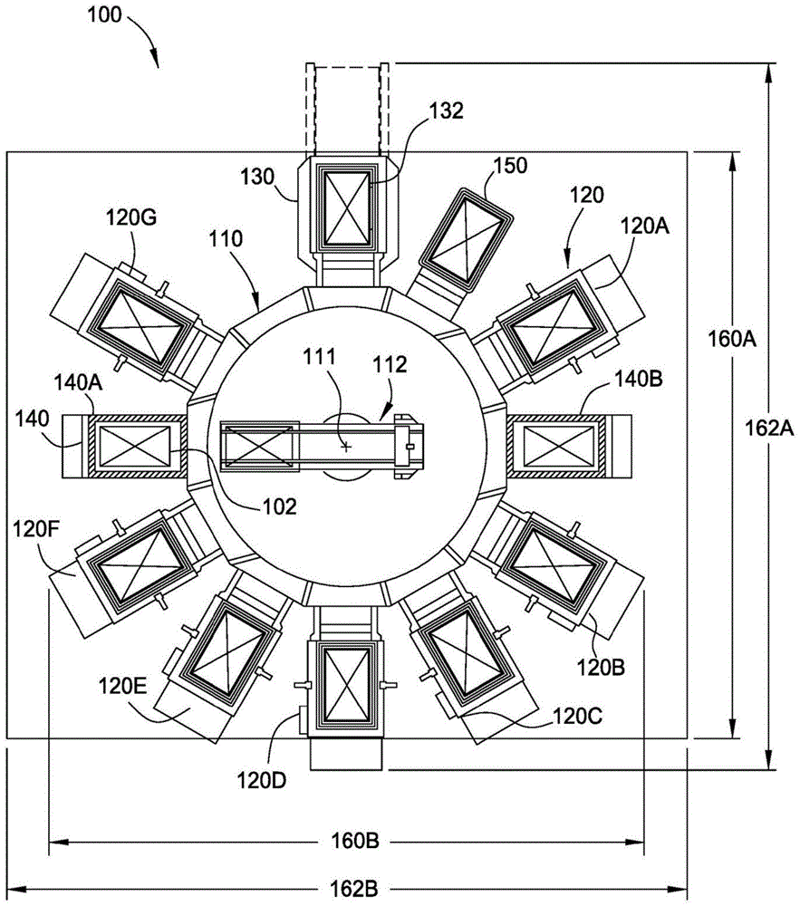
图1是根据一个实施方式的具有传送腔室的用于真空处理多个基板的处理系统的顶剖视图。1 is a top cross-sectional view of a processing system having a transfer chamber for vacuum processing a plurality of substrates according to one embodiment.
图2是根据一个实施方式的图1中的处理系统中所示的装载锁定腔室的侧剖视图。2 is a side cross-sectional view of the load lock chamber shown in the processing system of FIG. 1 according to one embodiment.
图3A是根据一个实施方式的图1的传送腔室的顶平面图。Figure 3A is a top plan view of the transfer chamber of Figure 1, according to one embodiment.
图3B是根据一个实施方式的图1的传送腔室的侧平面图。3B is a side plan view of the transfer chamber of FIG. 1, according to one embodiment.
图4是根据一个实施方式的用于图1的传送腔室中的机器人的侧剖视图。4 is a side cross-sectional view of a robot for use in the transfer chamber of FIG. 1 , according to one embodiment.
图5是根据一个实施方式的图1的缓冲腔室的侧剖视图。5 is a side cross-sectional view of the buffer chamber of FIG. 1 according to one embodiment.
图6是根据一个实施方式的图1的掩模腔室的侧剖视图。6 is a side cross-sectional view of the mask chamber of FIG. 1 according to one embodiment.
图7是根据一个实施方式的图1的处理系统的处理腔室中的一个处理腔室的侧剖视图。7 is a side cross-sectional view of one of the processing chambers of the processing system of FIG. 1 according to one embodiment.
图8是根据一个实施方式的图1中的传送腔室的操作的流程图。Figure 8 is a flowchart of the operation of the transfer chamber of Figure 1 according to one embodiment.
为了促进理解,已经尽可能地使用相同的附图标号标示各图共有的相同元件。将构想到,在一个实施方式中公开的元件可以有益地用于其它实施方式,而不再赘述。To facilitate understanding, identical reference numerals have been used wherever possible to designate identical elements that are common to the various figures. It is contemplated that elements disclosed in one embodiment may be beneficially utilized on other embodiments without further recitation.
具体实施方式detailed description
本公开的实施方式大体涉及一种用于真空处理大面积基板(例如,LCD、OLED和其它类型的平板显示器、太阳能面板和类似基板)的真空处理系统。虽然本文中描述了一种用于在大面积基板上执行沉积的真空处理系统,但是真空处理系统可以替代地被构造为在基板上执行其它真空工艺,诸如蚀刻、离子注入、退火、等离子体处理和物理气相沉积等等。Embodiments of the present disclosure generally relate to a vacuum processing system for vacuum processing large area substrates such as LCD, OLED, and other types of flat panel displays, solar panels, and similar substrates. Although a vacuum processing system is described herein for performing deposition on large area substrates, the vacuum processing system may alternatively be configured to perform other vacuum processes on substrates, such as etching, ion implantation, annealing, plasma processing and physical vapor deposition, etc.
图1是根据一个实施方式的用于在多个基板102上执行真空处理的处理系统100的顶剖视图。处理系统100具有传送腔室110。多个处理腔室120耦接到传送腔室110。另外,一个或多个装载锁定腔室140耦接到传送腔室110。任选地,掩模腔室130和缓冲腔室150中的一个或两个可以耦接到传送腔室110。传送腔室110、处理腔室120、装载锁定腔室140以及形成处理系统100的任何另外附接的腔室被密封地耦接以保持在其中的真空环境。1 is a top cross-sectional view of a
处理系统100经构造以保持和处理多个基板102。每个基板102具有长度、宽度和厚度。在一些实施方式中,基板102的长度可以比宽度长50%或更多。例如,在一个实施方式中,每个基板102具有约1500mm的长度和约925mm的宽度。基板102的厚度可以是几毫米或更少,诸如约0.3毫米至约0.5毫米厚。基板102可以由玻璃、塑料或其它材料构成。The
基板102可以通过装载锁定腔室140移入和移出处理系统100。简要地转到图2中所示的装载锁定腔室140的示意图,装载锁定腔室140可以是双单一腔装载锁定。装载锁定腔室140包括第一装载锁定空腔201(例如,下部装载锁定基板接收空腔)和设置在第一装载锁定空腔201上方的第二装载锁定空腔202(例如,上部装载锁定基板接收空腔)。第一装载锁定空腔201具有第一内部容积221。第二装载锁定空腔202具有第二内部容积222。每个内部容积221、222的大小被设计以将基板容纳在其中。
装载锁定腔室140还任选地包括分别耦接到第一装载锁定空腔201和第二装载锁定空腔202的内部容积221、222的下部排气系统和上部排气系统204。装载锁定腔室140可以任选地包括供气系统205,以用于向第一装载锁定空腔201和/或第二装载锁定空腔202提供处理气体。例如,处理气体可以包括惰性气体(诸如氩气),或其它处理惰性(process-inert)气体,诸如氮气。
第一装载锁定空腔201和第二装载锁定空腔202中的每个包括设置在内部容积221、222中的基板支撑件209,基板支撑件209经构造以将一个或多个基板102支撑在其上。基板支撑件209可以另外经构造以当基板102位于装载锁定空腔201、202中时旋转基板102。基板支撑件209可以旋转至少90度或甚至180度以对基板102进行定向。装载锁定腔室140可以在每个拐角处具有基板破损传感器以监控基板102的位置和状态。通过该布置,装载锁定腔室140可能能够将基板对准保持在250微米内。Each of the first
第一装载锁定空腔201和第二装载锁定空腔202中的每个包括相应的门206a、206b,相应的门206a、206b可以被打开以允许对装载锁定空腔201、202进行接取(access)来实现基板的进入和离开。例如,门206a、206b可以被打开以促进通过工厂接口(factoryinterface,FI,未示出)的朝向/来自制造设施的某些部分的基板的传送,或促进朝向来自从一般保持在大气压下的其它区域的基板的传送。在一个示例中,门206a可以被打开以允许第一装载锁定空腔201的接取来促进来自保持在大气压下的环境的基板的传送,而第二装载锁定空腔202的门206b可以被关闭以促进朝向保持在传送腔室110中的真空环境的基板的传送。Each of the first
第一装载锁定空腔201和第二装载锁定空腔202中的每个还包括相应的狭缝阀207a、207b,以使装载锁定腔室140与传送腔室110密封。狭缝阀207a、207b的操作促进朝向/来自处理系统100中的传送腔室110的基板102的传送。在一个方面,可以打开狭缝阀207a、207b以允许利用处理系统100的传送腔室110的基板传送。例如,狭缝阀207a可以打开以允许接取第一装载锁定空腔201来促进从第一装载锁定空腔201到处理系统100的传送腔室110的基板传送,而狭缝阀207b可以关闭以允许在门206b被打开时从大气接取第二装载锁定空腔202,来促进位于FI或其它大气区域处的第二装载锁定空腔202之间的基板传送。Each of the first
排气系统204耦接到第一装载锁定空腔201和第二装载锁定空腔202。排气系统204促进从第一装载锁定空腔201和第二装载锁定空腔202的内部容积中移除气体。排气系统204可以包括通过阀211、212耦接到装载锁定空腔201、202的泵213。第一内部容积221和第二内部容积222可以被抽空并在约780Torr至小于100m Torr的压力下操作。泵213可足以在小于约20秒内抽空第一内部容积221或第二内部容积222中的压力,即,将压力从780Torr减小到小于约100mTorr。类似地,阀211、212可以通气并使压力在20秒或更短的时间内从100mTorr返回到约780Torr。An
处理气体可以经由供气系统205供应到第一装载锁定空腔201或第二装载锁定空腔202。供气系统205包括第一阀215、216,第一阀215、,216将气体供源217耦接到第一装载锁定空腔201或第二装载锁定空腔202。Process gas may be supplied to the first
在另一个示例中,装载锁定腔室140可以包括单个装载锁定空腔,诸如第一装载锁定空腔201,使得装载锁定腔室140可以一次仅处理单个基板。在单个基板空腔的构造中,装载锁定腔室140可以用作穿通通路,以用于将处理系统100耦接到邻接的处理系统,使得基板可以在处理系统之间传送而不会破坏真空(即,不将基板暴露于大气压)。In another example, the
在如图1所示的又一个示例中,装载锁定腔室140A可以仅具有第一装载锁定空腔201,使得装载锁定腔室140A可以一次仅处理单个基板,而装载锁定腔室140B可以包括第一装载锁定空腔201和第二装载锁定空腔202两者,使得装载锁定腔室140B可以同时处理两个基板。因此,处理系统100可以经构造以通过装载锁定腔室140A而在相邻的处理系统之间传送基板,同时通过装载锁定腔室140B而利用大气工厂接口传送基板。In yet another example as shown in FIG. 1 , the
图3A是根据一个实施方式的图1的传送腔室110的顶平面图。图3B是图1的传送腔室110的侧平面图。现参考图1、图3A和图3B,装载锁定腔室140在狭缝阀207处耦接到传送腔室110的面310。传送腔室110具有盖364和底表面362。多个侧壁316将盖364密封地耦接到底表面362并限定内部容积302。盖364可以铰接到侧壁316并在打开位置和关闭位置之间是可移动的,打开位置将内部容积302暴露于传送腔室110外部的环境,关闭位置抵靠侧壁316形成气密密封。多个侧壁316形成传送腔室110的外周边314。如图3A的顶平面图所示,外周边314具有多边形形状,所述多边形形状具有十二个面310。处理系统100的中心111可以与传送腔室110的中心311重合。或者,中心311不与处理系统100的中心111对准。FIG. 3A is a top plan view of the
传送腔室110的面310具有穿过侧壁316形成的开口312。开口312的大小被设计以允许基板102穿过开口312并进入传送腔室110的内部容积302。例如,开口312具有大于基板102的宽度的水平宽度。在一个示例中,开口312具有至少925mm的水平宽度。面310是基本上平坦的,并且经构造以密封地接合其它腔室(120、130、140、150)中的一个。The
密封件、垫圈或其它合适的技术可以用于形成围绕面310中的开口312和邻接的处理腔室(诸如装载锁定腔室140、掩模腔室130、处理腔室120、缓冲腔室150或其它腔室)的密封。例如,可以利用O形环(未示出)在装载锁定腔室140与传送腔室110的面310中的开口312之间提供气密密封。装载锁定腔室140和传送腔室110之间的耦接通过密封件形成为气密密封,使得当狭缝阀207向传送腔室110开放时,装载锁定腔室140的内部容积221、222之间的大气压可以与传送腔室110的内部容积302一起被保持。Seals, gaskets, or other suitable techniques may be used to form surrounding
排气系统204耦接到传送腔室110。排气系统204从传送腔室110的内部容积302中移除气体,以在其中保持真空环境。排气系统204是可操作的,以在内部容积302内形成在约10Torr与约50mTorr之间的气氛。
双臂式真空传送机器人112设置在传送腔室110的内部容积302中。装载锁定腔室140中的基板102可以由传送机器人112通过狭缝阀207传送到传送腔室110中。参照图4,图4是根据一个实施方式的在图1的传送腔室110中使用的机器人112的一个实施方式的侧剖视图。A dual-armed
传送机器人112设置在传送腔室110中,并且可以用于移动基板102和掩模132朝向环绕传送腔室110的腔室(诸如处理腔室120、装载锁定腔室140和掩模腔室130),并从环绕传送腔室110的腔室移动基板102和掩模132。传送机器人112。传送机器人112具有设置在基部448上的主体446。传送机器人112可以任选地具有冷却板447。冷却板447可以附接到冷却流体源(未示出),冷却流体源提供传热流体以用于减少从基板102传递到传送机器人112的热量。主体446可在延伸穿过基部448的竖直轴线上旋转。A
传送机器人112具有附接到第一终端受动器442(即,上部终端受动器)的腕部445。腕部445和第一终端受动器442可以附接到引导件464。引导件464可以沿着主体446上的轨道463移动。腕部445和第一终端受动器442沿着轨道463是可水平移动的并相对于基部448旋转。第一终端受动器442包括基板支撑表面,所述基板支撑表面经构造以在基板102被传送机器人112移动的同时支撑基板102。腕部445和第一终端受动器442在缩回位置和延伸位置之间移动是可移动的,所述缩回位置基本上定位在主体446上方的中心,所述延伸位置使第一终端受动器442延伸而横向地超过主体446的前向部分449,使得第一终端受动器442可以定位在附接到传送腔室110的腔室中的一个腔室内,以促进与该腔室的基板传送。主体446可以旋转以使主体446的前向部分449在第一终端受动器442的延伸方向上与任何腔室进行定向和对准。The
在另一个示例中,腕部445和第一终端受动器442从传送腔室110的中心311横向地偏移,使得腕部445相对于相对端更靠近中心311。因此,用于传送机器人112的平衡中心411可以从以传送腔室110的中心311为中心的基部448偏移距离413。使第一终端受动器142从中心311偏移允许第一终端受动器442使用第一终端受动器442的运动的更短且花费更低的范围来横向地延伸以促进与其它腔室120、130、140、150的基板传送。为了平衡传送机器人112的重量,当在第一终端受动器442和/或第二终端受动器444上传送基板102时,平衡配重460可以设置在腕部445附近。In another example, the
传送机器人112能够同时将两个基板102或两个掩模132移动至环绕传送腔室110的腔室(诸如处理腔室120)中的一个腔室,和从环绕传送腔室110的腔室中的一个腔室移动两个基板102或两个掩模132。传送机器人112的第一终端受动器442可以具有足以支撑基板102的长度416和宽度。长度416平行于径向方向,在所述径向方向上,传送机器人112可以例如从传送腔室110的中心311径向地延伸到处理腔室120中的一个腔室中。传送机器人112可以在水平方向上延伸约5085毫米的距离并在竖直方向上移动约550毫米,以将基板102从一个腔室移动到另一个腔室。在一个实施方式中,传送机器人112的第一终端受动器442可以在水平方向上延伸约至少5000毫米的距离并在竖直方向上移动约至少540毫米的距离。传送机器人112可以具有小于0.5毫米的位置重复性(position repeatability),以防止基板损坏并增加产量。在一些实施方式中,传送机器人112可以包括上部终端受动器(即,第一终端受动器442)和下部终端受动器(即,第二终端受动器444),上部终端受动器和下部终端受动器可以允许传送机器人112使基板102和/或掩模132在第一终端受动器442和第二终端受动器444上彼此独立地移动。在一些实施方式中,第一终端受动器442和第二终端受动器444可以用于同时移动两个基板102或两个掩模132。当传送机器人112包括第一终端受动器442和第二终端受动器444时,每个终端受动器可以由电机独立地控制。在一个实施方式中,传送机器人112是具有第一终端受动器442和第二终端受动器444以及用于每个臂的单独电机的双臂式机器人。在另一个实施方式中,传送机器人112具有通过公共连杆耦接的第一终端受动器442和第二终端受动器444。传送机器人112可以足够快,以在小于约20秒内在处理腔室120与装载锁定腔室140之间交换基板102。另外,传送机器人112可以在小于约40秒内在掩模腔室130与处理腔室120之间交换掩模。The
基板芯片和对准检测器451(检测器451)可以任选地附接到传送机器人112的主体446。随着第一终端受动器442的延伸和缩回,设置在第一终端受动器442上的基板102行进通过检测器451。随着定位在第一终端受动器442上的基板102移动通过检测器451中的传感器,基板102相对于第一终端受动器442和第二终端受动器444的位置以及基板102的边缘上的缺陷被检测。A substrate chip and alignment detector 451 (detector 451 ) may optionally be attached to the
传送机器人112可以朝向和从装载锁定腔室140将基板102移入和移出处理腔室120。然而,在工艺中的下游发生的导致离开处理腔室120的基板102无处可去的时间期间,基板102可以被传送到缓冲腔室150中。图5是根据一个实施方式的图1中所示的缓冲腔室150的侧剖视图。缓冲腔室150经构造以在基板102等待被传送到处理系统100中的另一个腔室、或被传送出处理系统100时保持基板102。例如,第一基板可以被安排以用于在第一腔室中处理,所述第一腔室当前被在其中执行处理的第二基板所占据。第一基板可以由传送机器人112传送到缓冲腔室150,以在第一基板等待第一处理腔室可用的同时释放传送机器人112以将其它基板移入和移出其它腔室。The
缓冲腔室150可以具有盖508、壁506和底板504,盖508、壁506和底板504限定并封闭内部容积510。开口530可以形成在壁506中。开口530经构造以用于使基板102从中穿过。缓冲腔室150可以任选地具有用于开口530的狭缝阀或其它关闭机构。开口530另外经构造以与传送腔室110的面310中的开口312中的一个开口对准。可以利用密封件、垫圈或其它合适的技术在开口530周围形成密封,使得缓冲腔室150可以与传送腔室110的面310形成气密密封。缓冲腔室150的内部容积510可以是气密的,并且保持在小于约10mTorr的基础压力下。缓冲腔室150可以具有用于保持其中的压力的真空泵。或者,当缓冲腔室150内的压力与传送腔室110内的压力均衡时,可以通过开口312、530实现内部容积510中的压力。因此,缓冲腔室150可以具有类似于传送腔室110的操作温度,即,在约50mTorr至约100mTorr之间。The
缓冲腔室可以具有支撑架540。支撑架540由轴542支撑。轴542可以附接到驱动单元544。驱动单元544可以是线性电机、机械装置,液压单元或能够使轴542在延伸位置与缩回位置之间竖直地移动以升高和降低支撑架540的其它合适的移动机构。支撑架540可以具有槽524。每个槽524可以经构造以在其上接受基板102。支撑架540可以经构造以将多个基板102保持在相应的槽524中。例如,支撑架540可以具有六个槽524以用于在缓冲腔室150的内部容积510内将六个基板保持在其中。The buffer chamber may have a
支撑架540可以由驱动单元544升高或降低以使槽524与开口530对准,以用于由传送机器人112进行接取。传送机器人112可以将基板从槽524移动到装载锁定腔室140或在一些情况下移动到处理腔室120。传送机器人112可以另外将掩模132从掩模腔室130移动到处理腔室120以在其中处理基板102。图6是根据一个实施方式的图1的掩模腔室130的侧剖视图。
可以在处理系统100中执行的处理期间使用多个掩模132,如下文进一步描述的。掩模腔室130可以用于存储要在在不同处理腔室120中执行的工艺(诸如沉积工艺)中使用的掩模132。例如,掩模腔室130可以在一个或多个盒620中存储约4至约30个掩模132。每个掩模132具有长度和宽度,所述长度和宽度的大小可以被设计为与基板102的长度和宽度类似。
掩模腔室130包括腔室主体602,腔室主体602限定内部容积604。狭缝阀618可以耦接到腔室主体602。狭缝阀618耦接到处理系统100的传送腔室110,并且狭缝阀618经构造以允许朝向和来自内部容积604的掩模132的通道。传送机器人112能够在第一终端受动器442上以类似于移动基板102的方式将掩模132移入和移出狭缝阀618。The
盖构件606可以耦接到腔室主体602。盖构件606可以经构造以当盖构件606位于关闭位置(如图所示)时封闭内部容积604。轨道构件626可以耦接到腔室主体602。盖致动器628可以将盖构件606定位在打开或关闭位置中。在一个实施方式中,盖致动器628是空气气缸。盖构件606可以沿着轨道构件626相对于腔室主体602进行平移以打开和关闭通向内部容积604的入口。在一个实施方式中,盖构件606可以在第一方向上沿着轨道构件626平移,并且盒620可以移入和移出内部容积604。A
内部容积604的大小可以被设计以接收具有架622的盒620,架622经构造以可移除的方式将掩模132保持在其中。盒620可以由起重机(crane)或其它类似的设备输送到掩模腔室130并定位在内部容积604内。一个或多个对准致动器624可以耦接到腔室主体602。对准致动器624可以经构造以接合盒620的一部分并在盒620传送到内部容积604内的期间协助定位盒620。在一个实施方式中,对准致动器624是空气气缸。需要清洁或调节的使用过的掩模132可以通过打开盖构件606并移除容纳有使用过的掩模的盒620从掩模腔室130中移除。可以通过新盒620将新掩模132提供到掩模腔室130,并且然后可以关闭盖构件606。The
掩模腔室130可以经构造以在内部容积604中形成适于调节掩模132并更具体地是用于加热和冷却掩模132的环境。泵吸设备612可以耦接到腔室主体602并可以经构造以在容积中产生真空。在一个实施方式中,泵吸设备612是低温泵。泵吸设备612可以在容积中产生真空环境,所述真空环境可以基本上类似于与掩模腔室130耦接的传送腔室110的环境。由此,当狭缝阀618打开以接收或排出掩模132中的一个掩模时,可不破坏真空,这会提高掩模传送的效率。在一个实施方式中,掩模腔室130在约100mTorr至约760Torr的压力下操作。
加热构件644可以在内部容积604内并邻近盒620和掩模132而耦接到腔室主体602。加热构件644可以经构造以加热掩模132并也有助于冷却掩模132。在一个实施方式中,加热构件644可以是反射加热器或电阻加热器。加热构件644可以经构造以将掩模132加热和冷却到约20摄氏度与约100摄氏度之间的温度,诸如在约40摄氏度与约80摄氏度之间的温度。一般,可以加热新掩模并可以冷却使用过的掩模。温度传感器可以耦接到腔室主体602并延伸到内部容积604中,并且经构造以指示设置在其中的掩模132的温度。A
耦接到线性致动器并设置在内部容积604内的平台630可以经构造以接触盒620并将盒620平移通过内部容积604。在一个实施方式中,平台630经构造以在竖直方向上平移在约1500mm与约2500mm之间的行程距离,例如,在约2200mm与约2300mm之间的行程距离。平台630可以将架622相对于狭缝阀618定位在盒620中,使得掩模132可以从盒620中移除或放入到盒620中。传送机器人112可以将掩模移动到处理腔室120中以处理在其中的基板102。A
图7是根据一个实施方式的图1中所示的处理系统100的处理腔室120中的一个的侧剖视图。如图1所示,可以存在多个处理腔室120,诸如处理腔室120A至120F。处理腔室120A-120F都可以各自是化学气相沉积(CVD)腔室。或者,处理腔室120A-120F(统称处理腔室120)可以各自来自各种腔室,诸如CVD腔室、等离子体增强CVD腔室、原子层沉积腔室(ALD)或其它类型的沉积腔室。处理腔室120可以各自容纳一个或多个基板102和掩模132以使得能够在每个处理腔室120内的一个或多个基板102上执行诸如沉积工艺的工艺。在一个实施方式中,处理腔室120是CVD腔室,如下文进一步详细描述的。7 is a side cross-sectional view of one of the
处理腔室120包括腔室主体702。腔室主体702具有侧壁701。侧壁701环绕并限定腔室主体702内的处理空间716。侧壁701包括具有开口704的第一壁703。开口704可以通过狭缝阀或类似的设备的操作来打开和关闭。第一壁703大体上垂直于传送机器人112的延伸方向。第一壁703可以具有抵靠传送腔室110的面310的气密密封件。开口704可以与传送腔室110的开口312对准,并且经构造以由传送机器人112通过开口704将基板102和/或掩模132传送到处理腔室120的处理空间716中。The
泵吸设备(未示出)可以耦接到腔室主体702并可以经构造以在处理空间716中产生真空。在一个实施方式中,泵吸设备是低温泵。泵吸设备可以在处理空间716中产生真空环境,所述真空环境可以基本上类似于与处理腔室120耦接的传送腔室110的环境。由此,当狭缝阀打开以接收或排出掩模132或基板102中的一个时,不会破坏真空,这会提高处理腔室120的效率。在一个实施方式中,处理腔室120在约100mTorr至约2Torr的压力下操作。A pumping device (not shown) may be coupled to
处理腔室120包括基板支撑件709,基板支撑件709用于支撑一个或多个基板102。基板支撑件209包括支撑表面710,基板102在处理期间设置在支撑表面710上。基板支撑件709可以包括一个或多个加热元件715。在一个实施方式中,加热元件715具有流过其中的传热流体。在另一个实施方式中,加热元件715是电阻加热器。在其它实施方式中,一个或多个加热元件715可以经构造以提供基板支撑件709的加热的独立控制。例如,用于基板支撑件709的加热元件715可以被独立地控制并设置在加热区中。加热元件715可以将基板支撑件709加热到约50摄氏度与约100摄氏度之间。加热元件715可以经构造以将设置在基板支撑件209上的基板102保持在约77.5摄氏度与约82.5摄氏度之间的温度下。The
处理腔室120可以具有设置在其中的附加的加热器,以用于加热侧壁701的内表面705、扩散器712和腔室主体702。扩散器712和侧壁701可以具有设置在整体中的通道(未示出),以用于使传热流体流动。或者,扩散器712和侧壁701可以具有设置在其中的电阻加热器或其它合适的加热器。加热器可以将扩散器712保持在约50摄氏度与约100摄氏度之间的温度下。另外,设置在侧壁701中的加热器可以将处理腔室120的腔室主体702保持在约120摄氏度加或减约30摄氏度的温度下。The
基板102在处理期间在设置在与扩散器712相对的支撑表面710上。扩散器712包括多个开口714以允许处理气体进入限定在扩散器712与基板102之间的处理空间716。处理气体从一个或多个气源732输送通过形成在扩散器712上方的背板734中的开口,同时可以用射频源736向扩散器712提供电偏压。射频源736可以通过匹配盒(未示出)耦接,并产生变频RF以用于保持处理腔室120中的等离子体。
为了处理,掩模132初始通过第一壁中的开口704插入处理腔室120中,并且设置在多个运动对准元件718上。运动对准元件718具有致动器724,致动器724可在x方向751和y方向753上移动,并且经构造以使处理腔室120中的掩模132与基板102对准。然后,基板102也通过第一壁703中的开口704插入并设置在可延伸穿过基板支撑件709的支撑表面719的多个升降杆720上。然后,基板支撑件709升高以与基板102相会,使得基板102支撑在支撑表面710上。一旦基板102设置在支撑表面710上,一个或多个可视化系统722确定掩模132是否在基板102上正确对准。可视化系统722可以确定掩模132与基板102的对准在±10微米内。在装载基板期间,可视化系统722可以另外有助于使掩模上的SF载荷的对准在约±50微米内。如果掩模132未正确对准,那么对准系统的一个或多个致动器724在x方向751和/或y方向753上移动运动对准元件718中的一个或多个,以调整掩模132的位置。然后,一个或多个可视化系统722重新检查掩模132的对准。用致动器724调整掩模132的位置并重新检查位置的这个处理可以重复,直到掩模132在基板102上正确对准。For processing, the
一旦掩模132在基板102上正确对准,掩模132就下降到基板102上,并且然后基板支撑件709通过连接的轴726的移动而升高,直到掩模132接触任选的阴影框架728。在搁置在掩模132上前,阴影框架728设置在腔室主体702中的在从腔室主体702的侧壁701的一个或多个内表面705延伸的凸台(ledge)730上。基板支撑件209继续升高,直到基板102、掩模132和阴影框架728设置在处理位置中。然后,可以使用上述工艺,利用设置在每个基板102上方的掩模132,从而将一个或多个层707沉积在处理腔室120中的基板102上。例如,在一些实施方式中,层707中的一个或多个可以是含硅材料,诸如氮化硅、氧化硅、氮氧化硅和类似材料。可以将一个或多个层707沉积至约5,000埃至约10,000埃厚。Once the
回到图1,与常规系统相比,处理系统100的布局经构造以提高了产量并减少了系统占用空间。与具有每个基板约60秒的产量的常规系统相比,处理系统100可以具有每个基板约55秒的产量。Returning to FIG. 1 , the layout of the
处理系统100可以具有分别约15.40米×12.12米的长度160B和宽度160A。处理系统100的占用面积小于具有相当的产量的大多数的常规系统。有利地,与大多数的常规系统相比,处理系统100占据总地面空间的约3/5,而产量更大。这具有减小起重机的大小和维修区域的额外优点。例如,移动盒和其它设备的起重机可能需要在分别约12.9米和14.9米的宽度162A和长度162B上延伸。
为了了解通过用于处理系统100的配置在产量中获得的优点,现在将参考图8讨论处理系统的样本操作。图8是根据一个实施方式的图1中所示的传送腔室110的操作的流程图。In order to appreciate the advantages in throughput obtained by the configuration used for the
方法800开始于框810,其中七个基板被传送到传送腔室中。传送腔室具有十二个侧面和设置在其中的单个传送机器人。通过传送腔室机器人执行传送基板。传送腔室的十二个侧面中的每个经构造以接收并密封腔室,诸如处理腔室、缓冲腔室、掩模腔室或用于在真空环境中处理基板的其它处理设备。七个基板可以被传送通过第一装载锁定腔室中的一个或多个槽。在一个实施方式中,第一装载锁定腔室具有用于支撑基板的两个槽,并密封地附接到传送腔室的侧边中的一侧。第一基板和第二基板由传送腔室机器人从装载锁定腔室传送通过传送腔室。第三基板和第四基板移动到第一装载锁中,以便由传送机器人传送。随着基板由传送机器人移动到传送腔室中,通过将下一个基板移动到第一装载锁定腔室中来将下一个基板放入队列中。
由传送机器人将基板移动到耦接到传送腔室的处理腔室中。传送腔室具有沿着周边的十二个侧面,以允许12个室密封地耦接到传送腔室。传送腔室可以具有一个或多个装载锁定腔室和多个处理腔室。在一个实施方式中,传送腔室具有七个或更多个与之附接的处理腔室。传送腔室可以另外具有用于保持在处理腔室中使用的多个掩模的掩模腔室。掩模可以移动到每个相应的处理腔室以用于在其中处理基板。例如,来自直接附接到传送腔室的掩模腔室的掩模可以被传送到处理腔室中的一个。任选地,传送腔室可以具有用于保持在队列中等待移动通过传送腔室的基板的缓冲腔室。The substrate is moved by a transfer robot into a processing chamber coupled to the transfer chamber. The transfer chamber has twelve sides along the perimeter to allow 12 chambers to be sealingly coupled to the transfer chamber. The transfer chamber may have one or more load lock chambers and multiple process chambers. In one embodiment, the transfer chamber has seven or more processing chambers attached thereto. The transfer chamber may additionally have a mask chamber for holding a plurality of masks used in the processing chamber. A mask may be moved to each respective processing chamber for processing a substrate therein. For example, a mask from a mask chamber directly attached to the transfer chamber may be transferred to one of the processing chambers. Optionally, the transfer chamber may have a buffer chamber for holding substrates in queue waiting to move through the transfer chamber.
在框820处,含硅膜被沉积在直接附接到传送腔室的七个单独的处理腔室中的七个基板上。基板中的每个移动到相应的处理腔室中。或者,可以将两个基板移动到单个处理腔室中,以允许同时处理十四(14)个基板。含硅膜可以是SiO2、SiON或SiN等中的一种。At
在框830,在处理腔室中的一个中已经执行了单膜沉积之后,七个基板被传送出传送腔室。或者,基板可以在传送出传送腔室之前被传送到缓冲腔室。缓冲腔室可以允许处理持续执行而不必等待或将基板停放在处理腔室中的一个中。当每个基板从处理腔室移开时,在其中放置新基板。在一个实施方式中,机器人具有两个终端受动器,并且第一终端受动器从处理腔室中移除基板,而第二终端受动器将基板放置在处理腔室中以执行处理。这最小化了机器人移动并由此提高处理系统的产量。基板可以移动到第一装载锁定腔室或第二装载锁定腔室以从处理系统中移除。At
上述处理系统允许在大量基板上执行处理,同时仅使用相对小的占用面积。附接到单个传送腔室的多个处理腔室有利地为基板提供最小的处理时间,同时允许多个基板并行处理,从而使处理过的基板产生更高产量。更高产量以及更小的占用面积降低系统的操作成本和总制造成本。The processing systems described above allow processing to be performed on a large number of substrates while using only a relatively small footprint. Multiple processing chambers attached to a single transfer chamber advantageously provide minimal processing time for substrates while allowing parallel processing of multiple substrates resulting in higher throughput of processed substrates. Higher throughput and smaller footprint reduce system operating costs and overall manufacturing costs.
虽然前述内容针对本公开内容的实施方式,但是也可在不脱离本公开内容的基本范围的情况下设计本公开内容的其它和进一步实施方式,并且本公开内容的保护范围是由随附权利要求书确定。Although the foregoing is directed to embodiments of the present disclosure, other and further embodiments of the present disclosure can also be devised without departing from the essential scope of the present disclosure, and the scope of protection of the present disclosure is determined by the appended claims. Book OK.
Claims (1)
Applications Claiming Priority (4)
| Application Number | Priority Date | Filing Date | Title |
|---|---|---|---|
| US15/171,783 US20170352562A1 (en) | 2016-06-02 | 2016-06-02 | Dodecadon transfer chamber and processing system having the same |
| US15/171,783 | 2016-06-02 | ||
| CN201780033957.8A CN109314071B (en) | 2016-06-02 | 2017-05-02 | Dodecagonal transfer chamber and processing system with dodecagonal transfer chamber |
| PCT/US2017/030516 WO2017209881A1 (en) | 2016-06-02 | 2017-05-02 | Dodecadon transfer chamber and processing system having the same |
Related Parent Applications (1)
| Application Number | Title | Priority Date | Filing Date |
|---|---|---|---|
| CN201780033957.8A Division CN109314071B (en) | 2016-06-02 | 2017-05-02 | Dodecagonal transfer chamber and processing system with dodecagonal transfer chamber |
Publications (1)
| Publication Number | Publication Date |
|---|---|
| CN115440641A true CN115440641A (en) | 2022-12-06 |
Family
ID=60478813
Family Applications (2)
| Application Number | Title | Priority Date | Filing Date |
|---|---|---|---|
| CN201780033957.8A Active CN109314071B (en) | 2016-06-02 | 2017-05-02 | Dodecagonal transfer chamber and processing system with dodecagonal transfer chamber |
| CN202211014290.6A Pending CN115440641A (en) | 2016-06-02 | 2017-05-02 | Dodecagonal transfer chamber and processing system with dodecagonal transfer chamber |
Family Applications Before (1)
| Application Number | Title | Priority Date | Filing Date |
|---|---|---|---|
| CN201780033957.8A Active CN109314071B (en) | 2016-06-02 | 2017-05-02 | Dodecagonal transfer chamber and processing system with dodecagonal transfer chamber |
Country Status (6)
| Country | Link |
|---|---|
| US (1) | US20170352562A1 (en) |
| JP (1) | JP2019520701A (en) |
| KR (1) | KR102267964B1 (en) |
| CN (2) | CN109314071B (en) |
| TW (1) | TW201802999A (en) |
| WO (1) | WO2017209881A1 (en) |
Families Citing this family (8)
| Publication number | Priority date | Publication date | Assignee | Title |
|---|---|---|---|---|
| US11521876B2 (en) * | 2018-03-07 | 2022-12-06 | Tokyo Electron Limited | Horizontal substrate boat |
| JP2020520082A (en) * | 2018-04-26 | 2020-07-02 | アプライド マテリアルズ インコーポレイテッドApplied Materials,Incorporated | Vacuum processing system and method of operating a processing system |
| CN110211910B (en) * | 2019-07-02 | 2021-06-11 | 赣州卡奥斯新能源有限公司 | Photovoltaic solar silicon plate transmission device |
| US11443973B2 (en) * | 2019-07-12 | 2022-09-13 | Applied Materials, Inc. | Robot for simultaneous substrate transfer |
| US11049740B1 (en) | 2019-12-05 | 2021-06-29 | Applied Materials, Inc. | Reconfigurable mainframe with replaceable interface plate |
| CN112928043B (en) * | 2019-12-05 | 2022-07-22 | 应用材料公司 | Reconfigurable host with replaceable interface board |
| DE102020212223A1 (en) * | 2020-09-29 | 2022-03-31 | Robert Bosch Gesellschaft mit beschränkter Haftung | Non-contact conveyor |
| US11996307B2 (en) * | 2020-12-23 | 2024-05-28 | Applied Materials, Inc. | Semiconductor processing tool platform configuration with reduced footprint |
Citations (13)
| Publication number | Priority date | Publication date | Assignee | Title |
|---|---|---|---|---|
| US5811951A (en) * | 1996-10-14 | 1998-09-22 | Regents Of The University Of California | High precision redundant robotic manipulator |
| KR20010074681A (en) * | 1998-07-08 | 2001-08-09 | 세미툴 인코포레이티드 | Automated semiconductor processing system |
| US20020159864A1 (en) * | 2001-04-30 | 2002-10-31 | Applied Materials, Inc. | Triple chamber load lock |
| US20050095088A1 (en) * | 2003-10-20 | 2005-05-05 | Applied Materials, Inc. | Load lock chamber for large area substrate processing system |
| US20070026151A1 (en) * | 2005-07-13 | 2007-02-01 | Higginson John A | Fluid Deposition Cluster Tool |
| US20070147976A1 (en) * | 2005-12-22 | 2007-06-28 | Mike Rice | Substrate processing sequence in a cartesian robot cluster tool |
| US20070147982A1 (en) * | 2005-12-22 | 2007-06-28 | Applied Materials, Inc. | Method of retaining a substrate during a substrate transferring process |
| US20070292244A1 (en) * | 2006-06-15 | 2007-12-20 | Moore Robert B | Multi-level load lock chamber, transfer chamber, and robot suitable for interfacing with same |
| US20080118236A1 (en) * | 2006-08-14 | 2008-05-22 | Applied Materials, Inc. | Load lock chamber with heater in tube |
| CN101989562A (en) * | 2009-07-31 | 2011-03-23 | 东京毅力科创株式会社 | Assembly method of transfer mechanism and transfer chamber |
| US20110116900A1 (en) * | 2009-11-18 | 2011-05-19 | Applied Materials, Inc. | Substrate alignment apparatus |
| CN103703584A (en) * | 2011-06-17 | 2014-04-02 | 应用材料公司 | Mask management system and method for oled encapsulation |
| US20140261168A1 (en) * | 2013-03-14 | 2014-09-18 | Applied Materials, Inc. | Multiple chamber module and platform in semiconductor process equipment |
Family Cites Families (12)
| Publication number | Priority date | Publication date | Assignee | Title |
|---|---|---|---|---|
| US6122566A (en) * | 1998-03-03 | 2000-09-19 | Applied Materials Inc. | Method and apparatus for sequencing wafers in a multiple chamber, semiconductor wafer processing system |
| KR100342254B1 (en) * | 1999-06-25 | 2002-06-27 | 윤종용 | Loading robot having a balancing part |
| US20080025821A1 (en) * | 2006-07-25 | 2008-01-31 | Applied Materials, Inc. | Octagon transfer chamber |
| US20080099451A1 (en) * | 2006-10-30 | 2008-05-01 | Richard Lewington | Workpiece rotation apparatus for a plasma reactor system |
| JP5482500B2 (en) * | 2010-06-21 | 2014-05-07 | 東京エレクトロン株式会社 | Substrate processing equipment |
| JP5885404B2 (en) * | 2010-08-04 | 2016-03-15 | 株式会社日立国際電気 | Substrate processing apparatus and semiconductor device manufacturing method |
| US9312153B2 (en) * | 2010-08-06 | 2016-04-12 | Tokyo Electron Limited | Substrate processing system, transfer module, substrate processing method, and method for manufacturing semiconductor element |
| KR101293025B1 (en) * | 2011-12-22 | 2013-08-05 | 에스엔유 프리시젼 주식회사 | Mask Stock and Panel Passage Chamber, Method for Operating the same |
| TWI658531B (en) * | 2013-11-04 | 2019-05-01 | Applied Materials, Inc. | Transfer chamber having an increased number of sides, semiconductor device manufacturing processing tool, and processing method |
| CN106415876B (en) * | 2014-01-21 | 2018-06-26 | 应用材料公司 | Allow the thin-film package processing system and process kit that low-pressure tool is replaced |
| KR101612416B1 (en) * | 2014-04-22 | 2016-04-15 | 피에스케이 주식회사 | Apparatus and method for treating a substrate |
| US10236197B2 (en) * | 2014-11-06 | 2019-03-19 | Applied Materials, Inc. | Processing system containing an isolation region separating a deposition chamber from a treatment chamber |
-
2016
- 2016-06-02 US US15/171,783 patent/US20170352562A1/en not_active Abandoned
-
2017
- 2017-05-02 CN CN201780033957.8A patent/CN109314071B/en active Active
- 2017-05-02 KR KR1020187037681A patent/KR102267964B1/en active Active
- 2017-05-02 CN CN202211014290.6A patent/CN115440641A/en active Pending
- 2017-05-02 JP JP2018562289A patent/JP2019520701A/en active Pending
- 2017-05-02 WO PCT/US2017/030516 patent/WO2017209881A1/en not_active Ceased
- 2017-05-08 TW TW106115174A patent/TW201802999A/en unknown
Patent Citations (13)
| Publication number | Priority date | Publication date | Assignee | Title |
|---|---|---|---|---|
| US5811951A (en) * | 1996-10-14 | 1998-09-22 | Regents Of The University Of California | High precision redundant robotic manipulator |
| KR20010074681A (en) * | 1998-07-08 | 2001-08-09 | 세미툴 인코포레이티드 | Automated semiconductor processing system |
| US20020159864A1 (en) * | 2001-04-30 | 2002-10-31 | Applied Materials, Inc. | Triple chamber load lock |
| US20050095088A1 (en) * | 2003-10-20 | 2005-05-05 | Applied Materials, Inc. | Load lock chamber for large area substrate processing system |
| US20070026151A1 (en) * | 2005-07-13 | 2007-02-01 | Higginson John A | Fluid Deposition Cluster Tool |
| US20070147976A1 (en) * | 2005-12-22 | 2007-06-28 | Mike Rice | Substrate processing sequence in a cartesian robot cluster tool |
| US20070147982A1 (en) * | 2005-12-22 | 2007-06-28 | Applied Materials, Inc. | Method of retaining a substrate during a substrate transferring process |
| US20070292244A1 (en) * | 2006-06-15 | 2007-12-20 | Moore Robert B | Multi-level load lock chamber, transfer chamber, and robot suitable for interfacing with same |
| US20080118236A1 (en) * | 2006-08-14 | 2008-05-22 | Applied Materials, Inc. | Load lock chamber with heater in tube |
| CN101989562A (en) * | 2009-07-31 | 2011-03-23 | 东京毅力科创株式会社 | Assembly method of transfer mechanism and transfer chamber |
| US20110116900A1 (en) * | 2009-11-18 | 2011-05-19 | Applied Materials, Inc. | Substrate alignment apparatus |
| CN103703584A (en) * | 2011-06-17 | 2014-04-02 | 应用材料公司 | Mask management system and method for oled encapsulation |
| US20140261168A1 (en) * | 2013-03-14 | 2014-09-18 | Applied Materials, Inc. | Multiple chamber module and platform in semiconductor process equipment |
Also Published As
| Publication number | Publication date |
|---|---|
| KR20190000934A (en) | 2019-01-03 |
| KR102267964B1 (en) | 2021-06-21 |
| CN109314071B (en) | 2022-09-09 |
| CN109314071A (en) | 2019-02-05 |
| US20170352562A1 (en) | 2017-12-07 |
| TW201802999A (en) | 2018-01-16 |
| WO2017209881A1 (en) | 2017-12-07 |
| JP2019520701A (en) | 2019-07-18 |
Similar Documents
| Publication | Publication Date | Title |
|---|---|---|
| CN109314071B (en) | Dodecagonal transfer chamber and processing system with dodecagonal transfer chamber | |
| JP4559427B2 (en) | Substrate processing apparatus and semiconductor device manufacturing method | |
| JP4860167B2 (en) | Load lock device, processing system, and processing method | |
| US20030053893A1 (en) | Substrate processing apparatus and a method for fabricating a semiconductor device by using same | |
| WO2000028587A1 (en) | Processing device | |
| US20020197145A1 (en) | Substrate processing apparatus and a method for fabricating a semiconductor device by using same | |
| CN106971960A (en) | Apparatus and method for handling substrate | |
| TW201227864A (en) | Vacuum processing apparatus | |
| JP4916140B2 (en) | Vacuum processing system | |
| US20150096685A1 (en) | Vacuum processing apparatus | |
| JP4642619B2 (en) | Substrate processing system and method | |
| JP4744328B2 (en) | Semiconductor manufacturing apparatus provided with cooling stage and semiconductor manufacturing method using the same | |
| JPH09104982A (en) | Substrate processing equipment | |
| TW201349374A (en) | Substrate processing equipment | |
| JPH10107124A (en) | Substrate processing equipment | |
| JP3604241B2 (en) | Vertical heat treatment equipment | |
| JP4885023B2 (en) | Load lock device and substrate processing system | |
| US20170117169A1 (en) | Substrate cooling method, substrate transfer method, and load-lock mechanism | |
| JPH11102951A (en) | Processing equipment | |
| CN113728422A (en) | Vacuum processing apparatus | |
| JP3160691B2 (en) | Processing equipment | |
| KR102378336B1 (en) | Bake apparatus and bake method | |
| JP2004119627A (en) | Semiconductor manufacturing equipment | |
| KR102139613B1 (en) | Apparatus for transfer a substrate and apparatus for treating a substrate | |
| JPH1050802A (en) | Substrate processing equipment |
Legal Events
| Date | Code | Title | Description |
|---|---|---|---|
| PB01 | Publication | ||
| PB01 | Publication | ||
| SE01 | Entry into force of request for substantive examination | ||
| SE01 | Entry into force of request for substantive examination |