CN115416026A - Coordinate conversion method and device for robot and computer readable medium - Google Patents
Coordinate conversion method and device for robot and computer readable medium Download PDFInfo
- Publication number
- CN115416026A CN115416026A CN202211119315.9A CN202211119315A CN115416026A CN 115416026 A CN115416026 A CN 115416026A CN 202211119315 A CN202211119315 A CN 202211119315A CN 115416026 A CN115416026 A CN 115416026A
- Authority
- CN
- China
- Prior art keywords
- robot
- coordinate system
- coordinate
- virtual
- virtual robot
- Prior art date
- Legal status (The legal status is an assumption and is not a legal conclusion. Google has not performed a legal analysis and makes no representation as to the accuracy of the status listed.)
- Granted
Links
Images


Classifications
-
- B—PERFORMING OPERATIONS; TRANSPORTING
- B25—HAND TOOLS; PORTABLE POWER-DRIVEN TOOLS; MANIPULATORS
- B25J—MANIPULATORS; CHAMBERS PROVIDED WITH MANIPULATION DEVICES
- B25J9/00—Programme-controlled manipulators
- B25J9/16—Programme controls
- B25J9/1602—Programme controls characterised by the control system, structure, architecture
- B25J9/161—Hardware, e.g. neural networks, fuzzy logic, interfaces, processor
-
- B—PERFORMING OPERATIONS; TRANSPORTING
- B25—HAND TOOLS; PORTABLE POWER-DRIVEN TOOLS; MANIPULATORS
- B25J—MANIPULATORS; CHAMBERS PROVIDED WITH MANIPULATION DEVICES
- B25J9/00—Programme-controlled manipulators
- B25J9/16—Programme controls
- B25J9/1656—Programme controls characterised by programming, planning systems for manipulators
- B25J9/1671—Programme controls characterised by programming, planning systems for manipulators characterised by simulation, either to verify existing program or to create and verify new program, CAD/CAM oriented, graphic oriented programming systems
Landscapes
- Engineering & Computer Science (AREA)
- Robotics (AREA)
- Mechanical Engineering (AREA)
- Automation & Control Theory (AREA)
- Physics & Mathematics (AREA)
- Artificial Intelligence (AREA)
- Evolutionary Computation (AREA)
- Fuzzy Systems (AREA)
- Mathematical Physics (AREA)
- Software Systems (AREA)
- Manipulator (AREA)
Abstract
本发明公开了一种用于机器人的坐标转换方法、装置及计算机可读介质,属于机器人控制技术领域。该方法一具体实施方式包括:首先获取仿真环境下虚拟机器人的自身坐标系,以及虚拟机器人的末端相对于自身坐标系的坐标值;之后读取真实环境下实体机器人的末端相对于系统坐标系的坐标值;最后基于虚拟机器人的自身坐标系、虚拟机器人的末端坐标值以及实体机器人的末端坐标值;确定真实环境下实体机器人的系统坐标系。由此,将虚拟机器人的自身坐标系转换成系统坐标系,能够准确获取真实环境下实体机器人的系统坐标,从而在不了解实体机器人操作所参考的坐标系的情况下,将系统坐标系作为参考以有效控制实体机器人的工作。
The invention discloses a coordinate conversion method, device and computer-readable medium for a robot, belonging to the technical field of robot control. A specific implementation of the method includes: first obtaining the own coordinate system of the virtual robot in the simulation environment, and the coordinate value of the end of the virtual robot relative to the own coordinate system; and then reading the coordinate value of the end of the real robot relative to the system coordinate system in the real environment Coordinate value; Finally, based on the virtual robot's own coordinate system, the virtual robot's end coordinate value and the real robot's end coordinate value; determine the system coordinate system of the real robot in the real environment. Thus, converting the virtual robot's own coordinate system into the system coordinate system can accurately obtain the system coordinates of the physical robot in the real environment, so that the system coordinate system can be used as a reference without knowing the coordinate system referenced by the physical robot's operation. To effectively control the work of physical robots.
Description
技术领域technical field
本发明涉及机器人控制技术领域,尤其涉及一种用于机器人的坐标转换法、装置及计算机可读介质。The invention relates to the technical field of robot control, in particular to a coordinate transformation method, device and computer readable medium for a robot.
背景技术Background technique
相关技术中,在控制机器人工作过程中,往往需要提取设计机器人的工作路径,例如,在机器人进行焊接或者喷涂工作时,需要为工作机器人预先规划起始点、终止点以及轨迹行驶路线,从而控制实体机器人完成焊接工作或者喷涂工作;但是当前在规划机器人的工作路线时,存在的问题是实体机器人与控制系统中的虚拟机器人的坐标无法对应。In related technologies, in the process of controlling the work of the robot, it is often necessary to extract the working path of the designed robot. For example, when the robot performs welding or spraying work, it is necessary to pre-plan the starting point, ending point, and trajectory driving route for the working robot, so as to control the entity The robot completes the welding work or spraying work; however, when planning the working route of the robot, there is a problem that the coordinates of the physical robot and the virtual robot in the control system cannot correspond.
为此,现有技术通过获取真实环境下实体机器人的摆放姿态,并基于实体机器人的摆放姿态调整虚拟机器人的摆放姿态,从而使得实体机器人与虚拟机器人具有相同的摆放姿态;之后,控制系统通过控制虚拟机器人来控制实体机器人行走。然而,实际工作场景中还存在其他与实体机器人相连接的外部结构,例如外部轴、龙门架或者导轨;外部结构的摆放姿态对于实体机器人的行走将产生实质性的影响。另外,由于不能选取合适的机器人参考坐标系,因此导致控制系统通过虚拟机器人控制实体机器人工作时总是存在路径偏差,进而不能有效控制实体机器人工作。For this reason, the existing technology obtains the placement posture of the physical robot in the real environment, and adjusts the placement posture of the virtual robot based on the placement posture of the physical robot, so that the physical robot and the virtual robot have the same placement posture; after that, The control system controls the walking of the physical robot by controlling the virtual robot. However, there are other external structures connected to the physical robot in the actual work scene, such as external shafts, gantry frames or guide rails; the posture of the external structure will have a substantial impact on the walking of the physical robot. In addition, due to the inability to select a suitable robot reference coordinate system, there is always a path deviation when the control system controls the work of the real robot through the virtual robot, and thus cannot effectively control the work of the real robot.
发明内容Contents of the invention
本发明提供一种用于机器人的坐标转换法、装置及计算机可读介质、装置及计算机可读介质。该方法能够在不了解实体机器人操作所参考的坐标系的情况下,有效确定参考坐标系以控制实体机器人工作。The invention provides a coordinate transformation method for a robot, a device and a computer-readable medium, a device and a computer-readable medium. The method can effectively determine the reference coordinate system to control the work of the physical robot without knowing the reference coordinate system for the operation of the physical robot.
为实现上述目的,根据本申请实施例第一方面提供一种用于机器人的坐标转换方法,所述方法包括:获取仿真环境下虚拟机器人的自身坐标系,以及所述虚拟机器人的末端相对于所述自身坐标系的坐标值;读取真实环境下实体机器人的末端相对于系统坐标系的坐标值;基于所述虚拟机器人的自身坐标系、所述虚拟机器人的末端坐标值以及所述实体机器人的末端坐标值;确定真实环境下实体机器人的系统坐标系。In order to achieve the above purpose, according to the first aspect of the embodiment of the present application, a coordinate conversion method for a robot is provided, the method includes: obtaining the own coordinate system of the virtual robot in the simulation environment, and the end of the virtual robot relative to the Describe the coordinate value of its own coordinate system; read the coordinate value of the end of the real robot relative to the system coordinate system in the real environment; based on the own coordinate system of the virtual robot, the end coordinate value of the virtual robot and the End coordinate value; determine the system coordinate system of the real robot in the real environment.
可选的,所述方法还包括:确定真实环境下所述实体机器人关节角的角度,得到第一角度;获取真实环境下与所述实体机器人相连接外部结构关节角的角度,得到第二角度;基于所述第一角度调整所述仿真环境下待测机器人的的关节角,得到虚拟机器人;基于所述第二角度调整所述仿真环境下待测外部结构的关节角,得到虚拟外部结构;基于虚拟机器人以及所述虚拟外部结构,构建与真实环境对应的仿真环境。Optionally, the method further includes: determining the angle of the joint angle of the physical robot in the real environment to obtain the first angle; obtaining the angle of the joint angle of the external structure connected to the physical robot in the real environment to obtain the second angle ; adjusting the joint angle of the robot to be tested in the simulation environment based on the first angle to obtain a virtual robot; adjusting the joint angle of the external structure to be tested in the simulation environment based on the second angle to obtain a virtual external structure; Based on the virtual robot and the virtual external structure, a simulation environment corresponding to the real environment is constructed.
可选的,所述外部结构包括外部轴、龙门架以及导轨中的一种或多种。Optionally, the external structure includes one or more of external shafts, gantry frames and guide rails.
可选的,当所述自身坐标系为所述虚拟机器人的基础坐标系时;所述获取仿真环境下虚拟机器人的自身坐标系,以及虚拟机器人的末端相对于所述自身坐标系的坐标值;包括:以所述虚拟机器人的基座中心为坐标原点,获取仿真环境下虚拟机器人的基础坐标系;以所述基础坐标系为参考,获取所述虚拟机器人的末端相对于所述基础坐标系的坐标值。Optionally, when the self-coordinate system is the basic coordinate system of the virtual robot; the acquisition of the self-coordinate system of the virtual robot in the simulation environment, and the coordinate value of the end of the virtual robot relative to the self-coordinate system; The method includes: taking the center of the base of the virtual robot as the origin of coordinates, obtaining the basic coordinate system of the virtual robot in the simulation environment; taking the basic coordinate system as a reference, obtaining the position of the end of the virtual robot relative to the basic coordinate system coordinate value.
可选的,当所述自身坐标系为虚拟机器人的工具坐标系时,所述获取仿真环境下虚拟机器人的自身坐标系,以及所述虚拟机器人的末端相对于所述自身坐标系的坐标值,包括:获取所述仿真环境下虚拟机器人的工具坐标系;读取所述真实环境下实体机器人相对于基础坐标系的末端坐标值;基于所述实体机器人的末端坐标值以及所述虚拟机器人的工具坐标系,计算所述虚拟机器人的末端相对于所述工具坐标系的坐标值。Optionally, when the self-coordinate system is the tool coordinate system of the virtual robot, the acquisition of the self-coordinate system of the virtual robot in the simulation environment and the coordinate values of the end of the virtual robot relative to the self-coordinate system, Including: obtaining the tool coordinate system of the virtual robot in the simulation environment; reading the end coordinate value of the real robot relative to the base coordinate system in the real environment; based on the end coordinate value of the physical robot and the tool coordinate system of the virtual robot A coordinate system, calculating coordinate values of the end of the virtual robot relative to the tool coordinate system.
可选的,所述获取所述仿真环境下虚拟机器人的工具坐标系,包括:以所述虚拟机器人的基座中心为坐标原点,获取仿真环境下虚拟机器人的基础坐标系;获取实体机器人的机械臂所抓取的工具中心点(Tool Center Point,缩写TCP)坐标值;基于所述基础坐标系和所述TCP坐标值,确定所述仿真环境下虚拟机器人的工具坐标系。Optionally, the obtaining the tool coordinate system of the virtual robot in the simulation environment includes: taking the base center of the virtual robot as the coordinate origin, obtaining the basic coordinate system of the virtual robot in the simulation environment; obtaining the mechanical coordinate system of the physical robot. The coordinate value of the tool center point (Tool Center Point, TCP for short) grasped by the arm; based on the basic coordinate system and the TCP coordinate value, determine the tool coordinate system of the virtual robot in the simulation environment.
为实现上述目的,根据本申请实施例第二方面提供一种用于机器人的坐标转换装置,所述装置包括:第一获取模块,用于获取仿真环境下虚拟机器人的自身坐标系,以及所述虚拟机器人的末端相对于所述自身坐标系的坐标值;读取模块,用于读取真实环境下实体机器人的末端相对于系统坐标系的坐标值;第一确定模块,用于基于所述虚拟机器人的自身坐标系、所述虚拟机器人的末端坐标值以及所述实体机器人的末端坐标值;确定真实环境下实体机器人的系统坐标系。In order to achieve the above object, according to the second aspect of the embodiment of the present application, there is provided a coordinate conversion device for a robot, the device includes: a first acquisition module, used to acquire the own coordinate system of a virtual robot in a simulation environment, and the The coordinate value of the end of the virtual robot relative to the self-coordinate system; the reading module is used to read the coordinate value of the end of the real robot relative to the system coordinate system in the real environment; the first determination module is used for based on the virtual The robot's own coordinate system, the end coordinate values of the virtual robot and the end coordinate values of the physical robot; determine the system coordinate system of the real robot in the real environment.
可选的,所述装置还包括:第二确定模块,用于确定真实环境下所述实体机器人关节角的角度,得到第一角度;第二获取模块,用于获取真实环境下与所述实体机器人相连接外部结构关节角的角度,得到第二角度;调整模块,用于基于所述第一角度和所述第二角度调整所述仿真环境中待测机器人的的关节角,得到虚拟机器人。Optionally, the device further includes: a second determination module, configured to determine the angle of the joint angle of the entity robot in the real environment to obtain the first angle; a second acquisition module, configured to obtain the joint angle of the entity robot in the real environment The angle of the joint angle of the robot connected to the external structure is obtained to obtain a second angle; the adjustment module is configured to adjust the joint angle of the robot to be tested in the simulation environment based on the first angle and the second angle to obtain a virtual robot.
为实现上述目的,根据本申请实施例第三方面还提供一种电子设备,该电子设备包括:处理器,以及存储器,用于存储所述处理器的可执行指令;其中,所述处理器配置为经由执行所述可执行指令来执行如第一方面所述的用于机器人的坐标转换的方法。To achieve the above object, according to the third aspect of the embodiment of the present application, there is also provided an electronic device, the electronic device includes: a processor, and a memory for storing executable instructions of the processor; wherein, the processor is configured The method for coordinate conversion of a robot as described in the first aspect is performed by executing the executable instructions.
为实现上述目的,根据本申请实施例第四方面还提供一种计算机可读介质,其上存储有计算机程序,所述程序被处理器执行时实现如第一方面所述的用于机器人的坐标转换的方法。In order to achieve the above object, according to the fourth aspect of the embodiment of the present application, there is also provided a computer-readable medium, on which a computer program is stored, and when the program is executed by a processor, the coordinate system for the robot as described in the first aspect is realized. method of conversion.
与现有技术相比,本发明实施例提供一种用于机器人的坐标转换方法、装置及计算机可读介质,该方法一具体实施方式包括:首先获取仿真环境下虚拟机器人的自身坐标系,以及所述虚拟机器人的末端相对于所述自身坐标系的坐标值;之后读取真实环境下实体机器人的末端相对于系统坐标系的坐标值;最后基于所述虚拟机器人的自身坐标系、所述虚拟机器人的末端坐标值以及所述实体机器人的末端坐标值;确定真实环境下实体机器人的系统坐标系。本实施例基于仿真环境下虚拟机器人的末端相对于自身坐标系的坐标值,以及真实环境下实体机器人的末端相对于系统坐标系的坐标值确定实体机器人的系统坐标系,由此,能够准确获取真实环境下实体机器人的系统坐标系,从而有效控制实体机器人的工作,解决了现有技术中由于不能有效选取合适的机器人参考坐标系导致控制系统控制实体机器人工作时总是存在路径偏差的问题,进一步减少了实体机器人在工作中的误差,提高了机器人对目标工件加工的精度。Compared with the prior art, an embodiment of the present invention provides a coordinate transformation method, device, and computer-readable medium for a robot. A specific implementation of the method includes: first obtaining the own coordinate system of the virtual robot in the simulation environment, and The coordinate value of the end of the virtual robot relative to the self-coordinate system; then read the coordinate value of the end of the real robot relative to the system coordinate system in the real environment; finally, based on the self-coordinate system of the virtual robot, the virtual The end coordinate value of the robot and the end coordinate value of the physical robot; determine the system coordinate system of the physical robot in the real environment. In this embodiment, the system coordinate system of the physical robot is determined based on the coordinate values of the end of the virtual robot relative to its own coordinate system in the simulation environment and the coordinate values of the end of the physical robot relative to the system coordinate system in the real environment. The system coordinate system of the physical robot in the real environment, so as to effectively control the work of the physical robot, and solve the problem in the prior art that there is always a path deviation when the control system controls the physical robot to work due to the inability to effectively select a suitable robot reference coordinate system. The error of the physical robot in the work is further reduced, and the precision of the robot for processing the target workpiece is improved.
附图说明Description of drawings
后文将参照附图以示例性而非限制性的方式详细描述本发明的一些具体实施例。附图中相同的附图标记标示了相同或类似的部件或部分。本领域技术人员应该理解,这些附图未必是按比例绘制的。附图中:Hereinafter, some specific embodiments of the present invention will be described in detail by way of illustration and not limitation with reference to the accompanying drawings. The same reference numerals in the drawings designate the same or similar parts or parts. Those skilled in the art will appreciate that the drawings are not necessarily drawn to scale. In the attached picture:
图1为本发明一实施例提供的用于机器人的坐标转换方法的流程示意图;Fig. 1 is a schematic flow chart of a coordinate conversion method for a robot provided by an embodiment of the present invention;
图2为本发明一实施例中创建仿真环境下的虚拟机器人的流程示意图;Fig. 2 is a schematic flow diagram of creating a virtual robot in a simulation environment in an embodiment of the present invention;
图3为本发明一实施例中获取虚拟机器人的末端相对于基础坐标系的坐标值的流程示意图;FIG. 3 is a schematic flow diagram of obtaining the coordinate values of the end of the virtual robot relative to the base coordinate system in an embodiment of the present invention;
图4为本发明一实施例中获取虚拟机器人的末端相对于工具坐标系的坐标值的流程示意图;FIG. 4 is a schematic flow diagram of obtaining the coordinate values of the end of the virtual robot relative to the tool coordinate system in an embodiment of the present invention;
图5为本发明一实施例中提供的用于机器人的坐标转换装置的结构示意图。Fig. 5 is a schematic structural diagram of a coordinate conversion device for a robot provided in an embodiment of the present invention.
具体实施方式detailed description
为使本发明的目的、特征、优点能够更加的明显和易懂,下面将结合本发明实施例中的附图,对本发明实施例中的技术方案进行清楚、完整地描述,显然,所描述的实施例仅仅是本发明一部分实施例,而非全部实施例。基于本发明中的实施例,本领域技术人员在没有做出创造性劳动前提下所获得的所有其他实施例,都属于本发明保护的范围。In order to make the purpose, features and advantages of the present invention more obvious and understandable, the technical solutions in the embodiments of the present invention will be clearly and completely described below in conjunction with the accompanying drawings in the embodiments of the present invention. Obviously, the described The embodiments are only some of the embodiments of the present invention, but not all of them. Based on the embodiments of the present invention, all other embodiments obtained by those skilled in the art without making creative efforts belong to the protection scope of the present invention.
本发明可以应用于各种机器人控制系统、模拟仿真系统、在线控制软件、离线编程软件中,以模拟仿真系统/离线编程软件进行机器人控制为例进行示意性说明。The present invention can be applied to various robot control systems, simulation systems, on-line control software, and off-line programming software, and the robot control by the simulation system/off-line programming software is used as an example for schematic illustration.
为了保证工作过程中的顺畅,本实施例在控制实体机器人工作时,提前规划机器人的工作轨迹、入刀方向、终止点。本发明涉及到的机器人可以应用于各种实际工作场景,例如,焊接场景、码垛场景、喷涂场景等。In order to ensure a smooth working process, this embodiment plans the robot's working trajectory, knife-entry direction, and end point in advance when controlling the physical robot to work. The robot involved in the present invention can be applied to various actual working scenes, for example, welding scene, palletizing scene, spraying scene and so on.
本发明中所涉及的到机器人的包括但不限于:工业机器人和教育机器人,有3-6个自由度,本实施例以6个自由度进行示意说明,对应J1-J6关节,机器人上包括有:基座、肘部、腕部、臂部(机械臂,通过工具夹取各个工件)、法兰等,机器人内部包含有:伺服电机、传送带、出气口等。The robots involved in the present invention include but are not limited to: industrial robots and educational robots, which have 3-6 degrees of freedom. This embodiment uses 6 degrees of freedom for schematic illustration, corresponding to J1-J6 joints. : base, elbow, wrist, arm (mechanical arm, clamping each workpiece through tools), flange, etc. The interior of the robot includes: servo motor, conveyor belt, air outlet, etc.
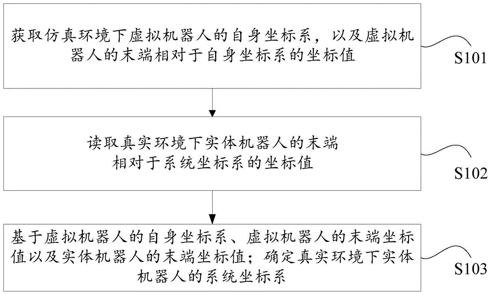
如图1所示,为本发明一实施例提供的用于机器人的坐标转换方法的流程示意图。一种用于机器人的坐标转换方法,所述方法至少包括如下步骤:As shown in FIG. 1 , it is a schematic flowchart of a coordinate transformation method for a robot provided by an embodiment of the present invention. A coordinate transformation method for a robot, said method at least comprising the following steps:
S101,获取仿真环境下虚拟机器人的自身坐标系,以及虚拟机器人的末端相对于自身坐标系的坐标值;S101, acquiring the own coordinate system of the virtual robot in the simulation environment, and the coordinate value of the end of the virtual robot relative to the own coordinate system;
S102,读取真实环境下实体机器人的末端相对于系统坐标系的坐标值;S102, read the coordinate value of the end of the physical robot relative to the system coordinate system in the real environment;
S103,基于虚拟机器人的自身坐标系、虚拟机器人的末端坐标值以及实体机器人的末端坐标值;确定真实环境下实体机器人的系统坐标系。S103, based on the virtual robot's own coordinate system, the virtual robot's end coordinate value and the real robot's end coordinate value; determine the system coordinate system of the real robot in the real environment.
在S101中,仿真环境是指与真实环境相同的环镜。在真实环境下存在实体机器人,以及与实体机器人相连接的外部结构;同理,在仿真环境下也存在与实体机器人结构相同的虚拟机器人,以及与实体外部结构相同的虚拟外部结构。虚拟机器人六个关节角的摆放姿态与实体机器人六个关节角的摆放姿态相同;同理,仿真环境下虚拟外部结构关节角的摆放姿态与真实环境下实体外部结构关节角的摆放姿态相同。In S101, the simulated environment refers to the same ring mirror as the real environment. In the real environment, there are physical robots and external structures connected with the physical robots; similarly, in the simulation environment, there are also virtual robots with the same structure as the physical robots, and virtual external structures with the same external structures as the physical ones. The placement posture of the six joint angles of the virtual robot is the same as that of the physical robot; similarly, the placement posture of the joint angles of the virtual external structure in the simulation environment is the same as that of the physical external structure joint angles in the real environment. The posture is the same.
在这里,关节角用于指示轴的角度。每个轴都有一个初始位置,将轴的初始位置作为机械零点,轴的角度都是相对于这个零点的。Here, joint angle is used to indicate the angle of the axis. Each axis has an initial position, and the initial position of the axis is used as the mechanical zero point, and the angle of the axis is relative to this zero point.
虚拟机器人的自身坐标系有两种,一种是虚拟机器人的基础坐标系,另一种是虚拟机器人的工具坐标系。虚拟机器人的工具是安装在虚拟机器人末端的,工具例如:焊枪、夹爪、激光切割头、电主轴或打磨头等。There are two kinds of self-coordinate systems of the virtual robot, one is the basic coordinate system of the virtual robot, and the other is the tool coordinate system of the virtual robot. The tools of the virtual robot are installed at the end of the virtual robot, such as welding guns, grippers, laser cutting heads, electric spindles or grinding heads, etc.
在S102中,基于真实环境中的示教器读取实体机器人末端点相对于系统坐标系的三维坐标,得到坐标值。In S102, based on the teaching pendant in the real environment, the three-dimensional coordinates of the end point of the physical robot relative to the system coordinate system are read to obtain coordinate values.
在这里,实体机器人末端点可以是机器人法兰末端的中心点,也可以是校准后的TCP末端。Here, the solid robot end point can be the center point of the robot flange end, or the calibrated TCP end.
在S103中,确定真实环境下实体机器人的系统坐标系时,所用到的计算公式如下式(1)所示。In S103, when determining the system coordinate system of the physical robot in the real environment, the calculation formula used is shown in the following formula (1).
M求×M输入=Mloc×Mtool 式(1);M seeking × M input = M loc × M tool formula (1);
其中Mloc是仿真环境下虚拟机器人的自身坐标系,Mtool是设置完关节角的角度后虚拟机器人末端相对自身坐标系的坐标值;M输入是在真实环境下通过示教器读取的机器人末端相对于系统坐标系的坐标;M求是真实环境下的系统坐标系。Among them, M loc is the virtual robot's own coordinate system in the simulation environment, M tool is the coordinate value of the end of the virtual robot relative to its own coordinate system after setting the joint angle; M input is the robot read through the teaching device in the real environment The coordinates of the end relative to the system coordinate system; M is the system coordinate system in the real environment.
本实施例通过构建与真实环境相同的仿真环境,并获取仿真环境中虚拟机器人的自身坐标系,以及虚拟机器人末端相对于自身坐标系的坐标值;之后通过示教器读取真实环境下机器人末端相对于系统坐标系的坐标值;最后根据虚拟机器人的自身坐标系、虚拟机器人末端的坐标值,以及实体机器人末端的坐标值,计算真实环境下的系统坐标系。由此,将虚拟机器人的自身坐标系转换成系统坐标系,从而在不了解实体机器人操作所参考的坐标系的情况下,将系统坐标系作为参考以有效控制实体机器人的工作,解决了现有技术中由于不能有效选取合适的机器人参考坐标系导致控制系统控制实体机器人工作时总是存在路径偏差的问题,进一步减少了实体机器人在工作中的误差,提高了机器人对目标工件加工的精度。This embodiment builds the same simulation environment as the real environment, and obtains the virtual robot's own coordinate system in the simulation environment, and the coordinate value of the end of the virtual robot relative to its own coordinate system; then reads the robot end in the real environment through the teaching pendant Coordinate values relative to the system coordinate system; finally, calculate the system coordinate system in the real environment based on the virtual robot's own coordinate system, the coordinate values of the end of the virtual robot, and the coordinate values of the end of the physical robot. Thus, the virtual robot's own coordinate system is converted into the system coordinate system, so that the system coordinate system can be used as a reference to effectively control the work of the physical robot without knowing the coordinate system referenced by the physical robot's operation. In the technology, due to the inability to effectively select a suitable robot reference coordinate system, there is always a problem of path deviation when the control system controls the physical robot to work, which further reduces the error of the physical robot during work and improves the precision of the robot's machining of the target workpiece.
需要说明的是,本实施例的实体机器人的类型为工业机器人或者教育机器人。It should be noted that the type of the physical robot in this embodiment is an industrial robot or an educational robot.
如图2所示,为本发明一实施例中创建仿真环境下的虚拟机器人的流程示意图;As shown in Figure 2, it is a schematic flow diagram of creating a virtual robot in a simulation environment in an embodiment of the present invention;
在本实施例优选的一实施方式中,创建仿真环境下的虚拟机器人,至少包括如下步骤:In a preferred implementation of this embodiment, creating a virtual robot in a simulation environment at least includes the following steps:
S201,确定真实环境下实体机器人关节角的角度,得到第一角度;S201. Determine the angle of the joint angle of the physical robot in the real environment to obtain the first angle;
S202,获取真实环境下与实体机器人相连接外部结构关节角的角度,得到第二角度;S202. Obtain the angle of the joint angle of the external structure connected with the physical robot in the real environment to obtain a second angle;
S203,基于第一角度调整仿真环境下待测机器人的关节角,得到虚拟机器人;S203, adjusting the joint angle of the robot to be tested in the simulation environment based on the first angle to obtain a virtual robot;
S204,基于第二角度调整仿真环境下待测外部结构的关节角,得到虚拟外部结构;S204, adjusting joint angles of the external structure to be measured in the simulation environment based on the second angle, to obtain a virtual external structure;
S205,基于虚拟机器人以及虚拟外部结构,构建与真实环境对应的仿真环境。S205, constructing a simulation environment corresponding to the real environment based on the virtual robot and the virtual external structure.
在这里,实体外部结构包括外部轴、龙门架以及导轨中的一种或多种。Here, the solid external structure includes one or more of external shafts, gantry frames, and guide rails.
具体地,通过真实环境下的示教器读取实体机器人J1关节至J6关节对应的第一角度,以及外部结构E1关节的第二角度;之后基于用户请求,生成虚拟机器人调试界面;其中,虚拟机器人调试界面至少包括J1关节选项、J2关节选项、J3关节选项、J4关节选项、J5关节选项、J6关节选项,以及外部结构E1关节选项;用户根据读取的实体机器人J1关节至J6关节对应的第一角度,以及外部结构E1关节的第二角度,触发调试界面,生成与真实环境摆放姿势相同的虚拟机器人以及虚拟外部结构;之后基于虚拟机器人以及虚拟外部结构,生成与真实环境对应的仿真环境。Specifically, read the first angle corresponding to the joints J1 to J6 of the physical robot through the teaching pendant in the real environment, and the second angle of the joint E1 of the external structure; then generate a virtual robot debugging interface based on user requests; where the virtual The robot debugging interface includes at least J1 joint options, J2 joint options, J3 joint options, J4 joint options, J5 joint options, J6 joint options, and external structure E1 joint options; The first angle and the second angle of the E1 joint of the external structure trigger the debugging interface to generate a virtual robot and a virtual external structure with the same posture as the real environment; then generate a simulation corresponding to the real environment based on the virtual robot and the virtual external structure environment.
由此,基于真实环境下实体机器人的摆放姿态以及实体外部结构的摆放姿态,调整仿真环境中的待测机器人和待测外部结构,从而能够准确构建与真实环境相同的仿真环境,有利于后期控制系统对实体机器人的控制,减少了不必要的误差,提高了实体机器人加工目标工件的精度。Therefore, based on the placement posture of the physical robot and the placement posture of the physical external structure in the real environment, the robot to be tested and the external structure to be tested in the simulation environment can be adjusted, so that the simulation environment that is the same as the real environment can be accurately constructed, which is beneficial The control of the physical robot by the later control system reduces unnecessary errors and improves the accuracy of the target workpiece processed by the physical robot.
如图3所示,为本发明一实施例中获取虚拟机器人的末端相对于基础坐标系的坐标值的流程示意图。As shown in FIG. 3 , it is a schematic flowchart of obtaining the coordinate values of the end of the virtual robot relative to the base coordinate system in an embodiment of the present invention.
在本实施例优选的另一实施方式中,当自身坐标系为虚拟机器人的基础坐标系时;获取虚拟机器人的末端相对于基础坐标系的坐标值;至少包括如下步骤:In another preferred implementation of this embodiment, when the own coordinate system is the basic coordinate system of the virtual robot; obtaining the coordinate value of the end of the virtual robot relative to the basic coordinate system; at least including the following steps:
S301,以虚拟机器人的基座中心为坐标原点,获取仿真环境下虚拟机器人的基础坐标系;S301, taking the center of the base of the virtual robot as the origin of coordinates, acquiring the basic coordinate system of the virtual robot in the simulation environment;
S302,以基础坐标系为参考,获取虚拟机器人的末端相对于基础坐标系的坐标值。S302. Using the base coordinate system as a reference, acquire the coordinate value of the end of the virtual robot relative to the base coordinate system.
具体地,基于用户对虚拟机器人的触发,生成坐标系界面;所述坐标系界面至少包括基础坐标系选项;基于用户对坐标系界面内基础坐标系选项的选择,生成基础坐标系;在选好基础坐标系作为参考坐标系后,基于用户对虚拟机器人末端所安装工具中心点的触发,获取虚拟机器人的末端的坐标值。Specifically, based on the triggering of the virtual robot by the user, a coordinate system interface is generated; the coordinate system interface includes at least the basic coordinate system option; based on the user's selection of the basic coordinate system option in the coordinate system interface, the basic coordinate system is generated; After the basic coordinate system is used as the reference coordinate system, the coordinate value of the end of the virtual robot is obtained based on the user triggering the center point of the tool installed at the end of the virtual robot.
如图4所示,为本发明一实施例中获取虚拟机器人的末端相对于工具坐标系的坐标值的流程示意图。As shown in FIG. 4 , it is a schematic flowchart of obtaining the coordinate values of the end of the virtual robot relative to the tool coordinate system in an embodiment of the present invention.
通在本实施例优选的又一实施方式中,当自身坐标系为虚拟机器人的工具坐标系时,获取虚拟机器人的末端相对于工具坐标系的坐标值,至少包括如下步骤:In yet another preferred implementation of this embodiment, when the own coordinate system is the tool coordinate system of the virtual robot, obtaining the coordinate value of the end of the virtual robot relative to the tool coordinate system at least includes the following steps:
S401,获取仿真环境下虚拟机器人的工具坐标系;S401, acquiring the tool coordinate system of the virtual robot in the simulation environment;
S402,读取真实环境下实体机器人相对于基础坐标系的末端坐标值;S402, reading the end coordinate value of the physical robot relative to the base coordinate system in the real environment;
S403,基于实体机器人的末端坐标值以及虚拟机器人的工具坐标系,计算虚拟机器人的末端相对于工具坐标系的坐标值。S403. Based on the end coordinate values of the physical robot and the tool coordinate system of the virtual robot, calculate the coordinate values of the end of the virtual robot relative to the tool coordinate system.
具体地,通过示教器读取实体机器人相对于工具坐标系的末端坐标值。基于如下计算公式计算虚拟机器人的末端相对于工具坐标系的坐标值,具体如式(2)所示。Specifically, read the end coordinate value of the physical robot relative to the tool coordinate system through the teaching pendant. Calculate the coordinate value of the end of the virtual robot relative to the tool coordinate system based on the following calculation formula, specifically as shown in formula (2).
M坐loc×M读=M世 式(2);M sits loc * M reads =M world formula (2);
其中,M坐loc为虚拟机器人的末端相对于工具坐标系的坐标值,M读为读取的实体机器人相对于基础坐标系的末端坐标值,M世为虚拟机器人的工具坐标系。Among them, Mloc is the coordinate value of the end of the virtual robot relative to the tool coordinate system, Mread is the read end coordinate value of the physical robot relative to the basic coordinate system, and Mshi is the tool coordinate system of the virtual robot.
在此基础上,进行反推可知,M坐loc=M世×M读的逆矩阵,通过求取M读逆矩阵,即可计算出虚拟机器人的末端相对于工具坐标系的坐标值。On this basis, the reverse deduction shows that the inverse matrix of Mloc = Mshi × Mread , by obtaining the inverse matrix of Mread, the coordinate value of the end of the virtual robot relative to the tool coordinate system can be calculated.
在本实施例中,可以通过实体机器人的末端坐标值,反推计算到的虚拟机器人的末端坐标值,能够保证实体机器人与虚拟机器人的末端坐标值天然匹配,从而让虚拟机器人与实体机器人对齐,提高实体机器人的轨迹规划效率和准确度,减少实体机器人在工作过程中出现的失误率,提高实体机器人生产的产品质量的合格率,从而解决相关技术中机器人坐标难以对齐,容易导致实体机器人在工作过程中出现失误,造成产品质量不合格的技术问题。In this embodiment, the calculated end coordinates of the virtual robot can be inversely deduced through the end coordinates of the physical robot, which can ensure that the end coordinates of the physical robot and the virtual robot naturally match, so that the virtual robot is aligned with the real robot. Improve the efficiency and accuracy of the trajectory planning of the physical robot, reduce the error rate of the physical robot during the working process, and improve the pass rate of the product quality produced by the physical robot, so as to solve the difficulty in aligning the robot coordinates in related technologies, which may easily cause the physical robot to work. Mistakes in the process, resulting in technical problems of unqualified product quality.
在本实施例的再一优选的实施方式中,确定仿真环境下虚拟机器人的工具坐标系,至少包括如下步骤:In yet another preferred implementation of this embodiment, determining the tool coordinate system of the virtual robot in the simulation environment at least includes the following steps:
S1,以虚拟机器人的基座中心为坐标原点,获取仿真环境下虚拟机器人的基础坐标系;S1, take the base center of the virtual robot as the coordinate origin, and obtain the basic coordinate system of the virtual robot in the simulation environment;
S2,获取实体机器人的机械臂所抓取的工具中心点TCP坐标值;S2, obtaining the TCP coordinate value of the tool center point captured by the mechanical arm of the physical robot;
S3,基于基础坐标系和所述TCP坐标值,确定仿真环境下虚拟机器人的工具坐标系。S3. Based on the basic coordinate system and the TCP coordinate value, determine the tool coordinate system of the virtual robot in the simulation environment.
具体地,根据如下式(3)计算仿真环境下虚拟机器人的工具坐标系M世。Specifically, the tool coordinate system M of the virtual robot in the simulation environment is calculated according to the following formula (3).
MFl xMTCP=M世 式(3);M Fl xM TCP = M formula (3);
其中,MFl用于指示虚拟机器人的基础坐标系,MTCP用于指示实体机器人的TCP坐标值。Among them, M Fl is used to indicate the basic coordinate system of the virtual robot, and M TCP is used to indicate the TCP coordinate value of the real robot.
在这里,TCP坐标值用于指示TCB三维坐标。Here, the TCP coordinate value is used to indicate the three-dimensional coordinates of the TCB.
需要说明的是,虚拟机器人的基础坐标系、工具坐标系以及系统坐标系分别与实体机器人的基础坐标系、工具坐标系以及系统坐标系是一一对应的。虚拟机器人的基础坐标系也就是虚拟机器人法兰对应的坐标系。It should be noted that the base coordinate system, the tool coordinate system and the system coordinate system of the virtual robot correspond to the base coordinate system, the tool coordinate system and the system coordinate system of the real robot respectively. The basic coordinate system of the virtual robot is also the coordinate system corresponding to the flange of the virtual robot.
由此,基于实体机器人的机械臂所抓取的工具中心点TCP坐标值,将虚拟机器人的基础坐标系转换为虚拟机器人的工具坐标系,有利于后期计算,提高了工作坐标系计算的准确率。Therefore, based on the TCP coordinate value of the tool center point captured by the mechanical arm of the physical robot, the basic coordinate system of the virtual robot is converted into the tool coordinate system of the virtual robot, which is beneficial to the later calculation and improves the accuracy of the calculation of the working coordinate system .
应理解,在本发明的各种实施例中,上述各过程的序号的大小并不意味着执行顺序的先后,各过程的执行顺序应以其功能和内在的逻辑确定,而不应对本发明实施例的实施过程构成任何限定。It should be understood that, in various embodiments of the present invention, the size of the sequence numbers of the above-mentioned processes does not mean the order of execution, and the execution order of each process should be determined by its functions and internal logic, and should not be used in the implementation of the present invention. The implementation of the examples constitutes no limitation.
下面结合具体的应用场景对本发明实施例进行详细说明。The embodiments of the present invention will be described in detail below in conjunction with specific application scenarios.
当所述自身坐标系为所述虚拟机器人的基础坐标系时,一种用于机器人的坐标转换方法,至少包括如下步骤:When the self-coordinate system is the basic coordinate system of the virtual robot, a coordinate conversion method for the robot at least includes the following steps:
S11,确定真实环境下实体机器人关节角的角度,得到第一角度;S11. Determine the angle of the joint angle of the physical robot in the real environment, and obtain the first angle;
S12,获取真实环境下与实体机器人相连接外部结构关节角的角度,得到第二角度;S12, obtaining the angle of the joint angle of the external structure connected with the physical robot in the real environment, and obtaining a second angle;
S13,基于第一角度调整仿真环境下待测机器人的关节角,得到虚拟机器人;S13, adjusting the joint angle of the robot to be tested in the simulation environment based on the first angle to obtain a virtual robot;
S14,基于第二角度调整仿真环境下待测外部结构的关节角,得到虚拟外部结构;S14, adjusting joint angles of the external structure to be tested in the simulation environment based on the second angle, to obtain a virtual external structure;
S15,基于虚拟机器人以及虚拟外部结构,构建与真实环境对应的仿真环境;S15, constructing a simulation environment corresponding to the real environment based on the virtual robot and the virtual external structure;
S16,以虚拟机器人的基座中心为坐标原点,获取仿真环境下虚拟机器人的基础坐标系;S16, taking the center of the base of the virtual robot as the origin of coordinates, obtaining the basic coordinate system of the virtual robot in the simulation environment;
S17,以基础坐标系为参考,获取虚拟机器人的末端相对于基础坐标系的坐标值;S17, taking the base coordinate system as a reference, acquiring the coordinate value of the end of the virtual robot relative to the base coordinate system;
S18,读取真实环境下实体机器人的末端相对于系统坐标系的坐标值;S18, reading the coordinate value of the end of the physical robot relative to the system coordinate system in the real environment;
S19,基于虚拟机器人的自身坐标系、虚拟机器人的末端坐标值以及实体机器人的末端坐标值;确定真实环境下实体机器人的系统坐标系。S19, based on the virtual robot's own coordinate system, the virtual robot's end coordinate value and the real robot's end coordinate value; determine the system coordinate system of the real robot in the real environment.
当所述自身坐标系为虚拟机器人的工具坐标系时,一种用于机器人的坐标转换方法,至少包括如下步骤:When the self-coordinate system is the tool coordinate system of the virtual robot, a coordinate conversion method for the robot at least includes the following steps:
S21,确定真实环境下实体机器人关节角的角度,得到第一角度;S21. Determine the angle of the joint angle of the physical robot in the real environment to obtain the first angle;
S22,获取真实环境下与实体机器人相连接外部结构关节角的角度,得到第二角度;S22. Obtain the angle of the joint angle of the external structure connected with the physical robot in the real environment to obtain a second angle;
S23,基于第一角度调整仿真环境下待测机器人的关节角,得到虚拟机器人;S23, adjusting the joint angle of the robot to be tested in the simulation environment based on the first angle to obtain a virtual robot;
S24,基于第二角度调整仿真环境下待测外部结构的关节角,得到虚拟外部结构;S24, adjusting joint angles of the external structure to be tested in the simulation environment based on the second angle, to obtain a virtual external structure;
S25,基于虚拟机器人以及虚拟外部结构,构建与真实环境对应的仿真环境;S25, constructing a simulation environment corresponding to the real environment based on the virtual robot and the virtual external structure;
S26,以虚拟机器人的基座中心为坐标原点,获取仿真环境下虚拟机器人的基础坐标系;S26, taking the center of the base of the virtual robot as the origin of coordinates, obtaining the basic coordinate system of the virtual robot in the simulation environment;
S27,获取实体机器人的机械臂所抓取的工具中心点TCP坐标值;S27, acquiring the TCP coordinate value of the tool center point captured by the mechanical arm of the physical robot;
S28,基于基础坐标系和TCP坐标值,确定仿真环境下虚拟机器人的工具坐标系;S28, based on the basic coordinate system and the TCP coordinate value, determine the tool coordinate system of the virtual robot in the simulation environment;
S29,读取真实环境下实体机器人相对于基础坐标系的末端坐标值;S29, reading the end coordinate value of the physical robot relative to the base coordinate system in the real environment;
S30,基于实体机器人的末端坐标值以及虚拟机器人的工具坐标系,计算虚拟机器人的末端相对于工具坐标系的坐标值;S30, based on the end coordinate value of the physical robot and the tool coordinate system of the virtual robot, calculate the coordinate value of the end of the virtual robot relative to the tool coordinate system;
S31,读取真实环境下实体机器人的末端相对于系统坐标系的坐标值;S31, reading the coordinate value of the end of the physical robot relative to the system coordinate system in the real environment;
S32,基于虚拟机器人的自身坐标系、虚拟机器人的末端坐标值以及实体机器人的末端坐标值;确定真实环境下实体机器人的系统坐标系。S32, based on the virtual robot's own coordinate system, the virtual robot's end coordinate value and the real robot's end coordinate value; determine the system coordinate system of the real robot in the real environment.
如图5所示,为本发明一实施例提供的用于机器人的坐标转换装置的结构示意图。一种用于机器人的坐标转换装置,该装置500包括:第一获取模块501,用于获取仿真环境下虚拟机器人的自身坐标系,以及所述虚拟机器人的末端相对于所述自身坐标系的坐标值;读取模块502,用于读取真实环境下实体机器人的末端相对于系统坐标系的坐标值;第一确定模块503,用于基于所述虚拟机器人的自身坐标系、所述虚拟机器人的末端坐标值以及所述实体机器人的末端坐标值;确定真实环境下实体机器人的系统坐标系。As shown in FIG. 5 , it is a schematic structural diagram of a coordinate conversion device for a robot provided by an embodiment of the present invention. A coordinate conversion device for a robot, the
在优选的实施方式中,所述的装置还包括:第二确定模块,用于确定真实环境下所述实体机器人关节角的角度,得到第一角度;第二获取模块,用于获取真实环境下与所述实体机器人相连接外部结构关节角的角度,得到第二角度;调整模块,用于基于所述第一角度和所述第二角度调整所述仿真环境中待测机器人的的关节角,得到虚拟机器人。In a preferred embodiment, the device further includes: a second determination module, configured to determine the angle of the joint angle of the physical robot in the real environment to obtain the first angle; a second acquisition module, configured to obtain the angle of the joint angle in the real environment The angle of the joint angle of the external structure connected with the physical robot to obtain a second angle; the adjustment module is used to adjust the joint angle of the robot to be tested in the simulation environment based on the first angle and the second angle, Get a virtual robot.
在优选的实施方式中,所述外部结构包括外部轴、龙门架以及导轨中的一种或多种。In a preferred embodiment, the external structure includes one or more of an external shaft, a gantry and a guide rail.
在优选的实施方式中,当所述自身坐标系为所述虚拟机器人的基础坐标系时;所述第一获取模块包括:第一获取单元,用于以所述虚拟机器人的基座中心为坐标原点,获取仿真环境下虚拟机器人的基础坐标系;第二获取单元,用于以所述基础坐标系为参考,获取所述虚拟机器人的末端相对于所述基础坐标系的坐标值。In a preferred embodiment, when the self-coordinate system is the basic coordinate system of the virtual robot; the first acquisition module includes: a first acquisition unit configured to take the base center of the virtual robot as the coordinate The origin is used to obtain the basic coordinate system of the virtual robot in the simulation environment; the second obtaining unit is configured to use the basic coordinate system as a reference to obtain the coordinate value of the end of the virtual robot relative to the basic coordinate system.
在优选的实施方式中,当所述自身坐标系为虚拟机器人的工具坐标系时,所述第一获取模块包括:第三获取单元,还用于获取所述仿真环境下虚拟机器人的工具坐标系;读取单元,用于读取所述真实环境下实体机器人相对于基础坐标系的末端坐标值;计算单元,用于基于所述实体机器人的末端坐标值以及所述虚拟机器人的工具坐标系,计算所述虚拟机器人的末端相对于所述工具坐标系的坐标值。In a preferred embodiment, when the self-coordinate system is the tool coordinate system of the virtual robot, the first acquisition module includes: a third acquisition unit, which is also used to acquire the tool coordinate system of the virtual robot in the simulation environment The reading unit is used to read the end coordinate value of the real robot relative to the base coordinate system in the real environment; the calculation unit is used to read the end coordinate value of the real robot and the tool coordinate system of the virtual robot, Calculate the coordinate value of the end of the virtual robot relative to the tool coordinate system.
在优选的实施方式中,所述第三获取单元包括:第一获取子单元,用于以所述虚拟机器人的基座中心为坐标原点,获取仿真环境下虚拟机器人的基础坐标系;第二获取子单元,用于获取实体机器人的机械臂所抓取的工具中心点的TCP坐标值;确定子单元,用于基于所述基础坐标系和所述TCP坐标值,确定所述仿真环境下虚拟机器人的工具坐标系。In a preferred embodiment, the third acquiring unit includes: a first acquiring subunit, configured to take the center of the base of the virtual robot as the origin of coordinates, and acquire the basic coordinate system of the virtual robot in the simulation environment; the second acquiring The subunit is used to obtain the TCP coordinate value of the tool center point grabbed by the mechanical arm of the physical robot; the determination subunit is used to determine the virtual robot in the simulation environment based on the basic coordinate system and the TCP coordinate value the tool coordinate system.
上述装置可执行本发明一实施例所提供的用于机器人的坐标转换方法,具备执行用于机器人的坐标转换方法相应的功能模块和有益效果。未在本实施例中详尽描述的技术细节,可参见本发明实施例所提供的用于机器人的坐标转换方法。The above-mentioned device can execute the coordinate transformation method for robots provided by an embodiment of the present invention, and has corresponding functional modules and beneficial effects for executing the coordinate transformation method for robots. For technical details not described in detail in this embodiment, refer to the coordinate conversion method for a robot provided in the embodiment of the present invention.
本发明还提供一种电子设备,包括:处理器;用于存储所述处理器可执行指令的存储器;所述处理器,用于从所述存储器中读取所述可执行指令,并执行所述指令以实现本发明所述的用于机器人的坐标转换方法。The present invention also provides an electronic device, including: a processor; a memory for storing instructions executable by the processor; the processor is used for reading the executable instructions from the memory and executing the The above instructions are used to realize the coordinate conversion method for a robot described in the present invention.
除了上述方法和设备以外,本申请的实施例还可以是计算机程序产品,其包括计算机程序指令,所述计算机程序指令在被处理器运行时使得所述处理器执行本说明书上述“示例性方法”部分中描述的根据本申请各种实施例的方法中的步骤。In addition to the above-mentioned methods and devices, embodiments of the present application may also be computer program products, which include computer program instructions that, when executed by a processor, cause the processor to perform the above-mentioned "exemplary method" of this specification. Steps in methods according to various embodiments of the application described in section.
所述计算机程序产品可以以一种或多种程序设计语言的任意组合来编写用于执行本申请实施例操作的程序代码,所述程序设计语言包括面向对象的程序设计语言,诸如Java、C++等,还包括常规的过程式程序设计语言,诸如“C”语言或类似的程序设计语言。程序代码可以完全地在用户计算设备上执行、部分地在用户设备上执行、作为一个独立的软件包执行、部分在用户计算设备上部分在远程计算设备上执行、或者完全在远程计算设备或服务器上执行。The computer program product can be written in any combination of one or more programming languages for executing the program codes for the operations of the embodiments of the present application, and the programming languages include object-oriented programming languages, such as Java, C++, etc. , also includes conventional procedural programming languages, such as the "C" language or similar programming languages. The program code may execute entirely on the user's computing device, partly on the user's device, as a stand-alone software package, partly on the user's computing device and partly on a remote computing device, or entirely on the remote computing device or server to execute.
此外,本申请的实施例还可以是计算机可读存储介质,其上存储有计算机程序指令,所述计算机程序指令在被处理器运行时使得所述处理器执行本说明书上述“示例性方法”部分中描述的根据本申请如下各实施例的方法中的步骤。In addition, the embodiments of the present application may also be a computer-readable storage medium, on which computer program instructions are stored, and when the computer program instructions are executed by a processor, the processor executes the above-mentioned "Exemplary Method" section of this specification. The steps in the method described in the following embodiments of the present application.
所述计算机可读存储介质可以采用一个或多个可读介质的任意组合。可读介质可以是可读信号介质或者可读存储介质。可读存储介质例如可以包括但不限于电、磁、光、电磁、红外线、或半导体的系统、装置或器件,或者任意以上的组合。可读存储介质的更具体的例子(非穷举的列表)包括:具有一个或多个导线的电连接、便携式盘、硬盘、随机存取存储器(RAM)、只读存储器(ROM)、可擦式可编程只读存储器(EPROM或闪存)、光纤、便携式紧凑盘只读存储器(CD-ROM)、光存储器件、磁存储器件、或者上述的任意合适的组合。The computer readable storage medium may employ any combination of one or more readable media. The readable medium may be a readable signal medium or a readable storage medium. The readable storage medium may include, but not limited to, electronic, magnetic, optical, electromagnetic, infrared, or semiconductor systems, devices, or devices, or any combination thereof. More specific examples (non-exhaustive list) of readable storage media include: electrical connection with one or more conductors, portable disk, hard disk, random access memory (RAM), read only memory (ROM), erasable programmable read-only memory (EPROM or flash memory), optical fiber, portable compact disk read-only memory (CD-ROM), optical storage devices, magnetic storage devices, or any suitable combination of the foregoing.
以上结合具体实施例描述了本申请的基本原理,但是,需要指出的是,在本申请中提及的优点、优势、效果等仅是示例而非限制,不能认为这些优点、优势、效果等是本申请的各个实施例必须具备的。另外,上述公开的具体细节仅是为了示例的作用和便于理解的作用,而非限制,上述细节并不限制本申请为必须采用上述具体的细节来实现。The basic principles of the present application have been described above in conjunction with specific embodiments, but it should be pointed out that the advantages, advantages, effects, etc. mentioned in the application are only examples rather than limitations, and these advantages, advantages, effects, etc. Various embodiments of this application must have. In addition, the specific details disclosed above are only for the purpose of illustration and understanding, rather than limitation, and the above details do not limit the application to be implemented by using the above specific details.
本申请中涉及的器件、装置、设备、系统的方框图仅作为例示性的例子并且不意图要求或暗示必须按照方框图示出的方式进行连接、布置、配置。如本领域技术人员将认识到的,可以按任意方式连接、布置、配置这些器件、装置、设备、系统。诸如“包括”、“包含”、“具有”等等的词语是开放性词汇,指“包括但不限于”,且可与其互换使用。这里所使用的词汇“或”和“和”指词汇“和/或”,且可与其互换使用,除非上下文明确指示不是如此。这里所使用的词汇“诸如”指词组“如但不限于”,且可与其互换使用。The block diagrams of devices, devices, devices, and systems involved in this application are only illustrative examples and are not intended to require or imply that they must be connected, arranged, and configured in the manner shown in the block diagrams. As will be appreciated by those skilled in the art, these devices, devices, devices, systems may be connected, arranged, configured in any manner. Words such as "including", "comprising", "having" and the like are open-ended words meaning "including but not limited to" and may be used interchangeably therewith. As used herein, the words "or" and "and" refer to the word "and/or" and are used interchangeably therewith, unless the context clearly dictates otherwise. As used herein, the word "such as" refers to and is used interchangeably with the phrase "such as but not limited to".
还需要指出的是,在本申请的装置、设备和方法中,各部件或各步骤是可以分解和/或重新组合的。这些分解和/或重新组合应视为本申请的等效方案。It should also be pointed out that in the devices, equipment and methods of the present application, each component or each step can be decomposed and/or reassembled. These decompositions and/or recombinations should be considered equivalents of this application.
提供所公开的方面的以上描述以使本领域的任何技术人员能够做出或者使用本申请。对这些方面的各种修改对于本领域技术人员而言是非常显而易见的,并且在此定义的一般原理可以应用于其他方面而不脱离本申请的范围。因此,本申请不意图被限制到在此示出的方面,而是按照与在此公开的原理和新颖的特征一致的最宽范围。The above description of the disclosed aspects is provided to enable any person skilled in the art to make or use the present application. Various modifications to these aspects will be readily apparent to those skilled in the art, and the generic principles defined herein may be applied to other aspects without departing from the scope of the application. Thus, the present application is not intended to be limited to the aspects shown herein but is to be accorded the widest scope consistent with the principles and novel features disclosed herein.
为了例示和描述的目的已经给出了以上描述。此外,此描述不意图将本申请的实施例限制到在此公开的形式。尽管以上已经讨论了多个示例方面和实施例,但是本领域技术人员将认识到其某些变型、修改、改变、添加和子组合。The foregoing description has been presented for purposes of illustration and description. Furthermore, this description is not intended to limit the embodiments of the application to the forms disclosed herein. Although a number of example aspects and embodiments have been discussed above, those skilled in the art will recognize certain variations, modifications, changes, additions and sub-combinations thereof.
在本说明书的描述中,参考术语“一个实施例”、“一些实施例”、“示例”、“具体示例”、或“一些示例”等的描述意指结合该实施例或示例描述的具体特征、结构、材料或者特点包含于本发明的至少一个实施例或示例中。而且,描述的具体特征、结构、材料或者特点可以在任一个或多个实施例或示例中以合适的方式结合。此外,在不相互矛盾的情况下,本领域的技术人员可以将本说明书中描述的不同实施例或示例以及不同实施例或示例的特征进行结合和组合。In the description of this specification, descriptions with reference to the terms "one embodiment", "some embodiments", "example", "specific examples", or "some examples" mean that specific features described in connection with the embodiment or example , structure, material or feature is included in at least one embodiment or example of the present invention. Furthermore, the described specific features, structures, materials or characteristics may be combined in any suitable manner in any one or more embodiments or examples. In addition, those skilled in the art can combine and combine different embodiments or examples and features of different embodiments or examples described in this specification without conflicting with each other.
此外,术语“第一”、“第二”仅用于描述目的,而不能理解为指示或暗示相对重要性或者隐含指明所指示的技术特征的数量。由此,限定有“第一”、“第二”的特征可以明示或隐含地包括至少一个该特征。在本发明的描述中,“多个”的含义是两个或两个以上,除非另有明确具体的限定。In addition, the terms "first" and "second" are used for descriptive purposes only, and cannot be interpreted as indicating or implying relative importance or implicitly specifying the quantity of indicated technical features. Thus, the features defined as "first" and "second" may explicitly or implicitly include at least one of these features. In the description of the present invention, "plurality" means two or more, unless otherwise specifically defined.
以上所述,仅为本发明的具体实施方式,但本发明的保护范围并不局限于此,任何熟悉本技术领域的技术人员在本发明揭露的技术范围内,可轻易想到变化或替换,都应涵盖在本发明的保护范围之内。因此,本发明的保护范围应以所述权利要求的保护范围为准。The above is only a specific embodiment of the present invention, but the scope of protection of the present invention is not limited thereto. Anyone skilled in the art can easily think of changes or substitutions within the technical scope disclosed in the present invention. Should be covered within the protection scope of the present invention. Therefore, the protection scope of the present invention should be determined by the protection scope of the claims.
Claims (10)
Priority Applications (1)
| Application Number | Priority Date | Filing Date | Title |
|---|---|---|---|
| CN202211119315.9A CN115416026B (en) | 2022-09-13 | 2022-09-13 | Coordinate conversion method, device and computer-readable medium for robot |
Applications Claiming Priority (1)
| Application Number | Priority Date | Filing Date | Title |
|---|---|---|---|
| CN202211119315.9A CN115416026B (en) | 2022-09-13 | 2022-09-13 | Coordinate conversion method, device and computer-readable medium for robot |
Publications (2)
| Publication Number | Publication Date |
|---|---|
| CN115416026A true CN115416026A (en) | 2022-12-02 |
| CN115416026B CN115416026B (en) | 2025-09-30 |
Family
ID=84202754
Family Applications (1)
| Application Number | Title | Priority Date | Filing Date |
|---|---|---|---|
| CN202211119315.9A Active CN115416026B (en) | 2022-09-13 | 2022-09-13 | Coordinate conversion method, device and computer-readable medium for robot |
Country Status (1)
| Country | Link |
|---|---|
| CN (1) | CN115416026B (en) |
Citations (5)
| Publication number | Priority date | Publication date | Assignee | Title |
|---|---|---|---|---|
| WO2019120481A1 (en) * | 2017-12-19 | 2019-06-27 | Abb Schweiz Ag | System and method for determining a transformation representation |
| CN110238831A (en) * | 2019-07-23 | 2019-09-17 | 青岛理工大学 | Robot teaching system and method based on RGB-D image and teaching device |
| CN111975781A (en) * | 2020-08-25 | 2020-11-24 | 北京华航唯实机器人科技股份有限公司 | Robot correction method and device and robot |
| CN112233172A (en) * | 2020-09-30 | 2021-01-15 | 北京零境科技有限公司 | Video penetration type mixed reality method, system, readable storage medium and electronic equipment |
| CN114029950A (en) * | 2021-11-08 | 2022-02-11 | 北京华航唯实机器人科技股份有限公司 | Robot coordinate system analysis method and device, robot device and storage medium |
-
2022
- 2022-09-13 CN CN202211119315.9A patent/CN115416026B/en active Active
Patent Citations (5)
| Publication number | Priority date | Publication date | Assignee | Title |
|---|---|---|---|---|
| WO2019120481A1 (en) * | 2017-12-19 | 2019-06-27 | Abb Schweiz Ag | System and method for determining a transformation representation |
| CN110238831A (en) * | 2019-07-23 | 2019-09-17 | 青岛理工大学 | Robot teaching system and method based on RGB-D image and teaching device |
| CN111975781A (en) * | 2020-08-25 | 2020-11-24 | 北京华航唯实机器人科技股份有限公司 | Robot correction method and device and robot |
| CN112233172A (en) * | 2020-09-30 | 2021-01-15 | 北京零境科技有限公司 | Video penetration type mixed reality method, system, readable storage medium and electronic equipment |
| CN114029950A (en) * | 2021-11-08 | 2022-02-11 | 北京华航唯实机器人科技股份有限公司 | Robot coordinate system analysis method and device, robot device and storage medium |
Non-Patent Citations (1)
| Title |
|---|
| 陈国栋;贾培发;王荣军;: "光学定位脑外科机器人系统及其空间配准", 仪器仪表学报, no. 03, 28 March 2007 (2007-03-28), pages 499 - 503 * |
Also Published As
| Publication number | Publication date |
|---|---|
| CN115416026B (en) | 2025-09-30 |
Similar Documents
| Publication | Publication Date | Title |
|---|---|---|
| CN108748159B (en) | Self-calibration method for tool coordinate system of mechanical arm | |
| CN206263418U (en) | A kind of real-time seam tracking system of six degree of freedom welding robot line laser | |
| Baeten et al. | Hybrid vision/force control at corners in planar robotic-contour following | |
| Geng et al. | A novel welding path planning method based on point cloud for robotic welding of impeller blades | |
| CN104552341B (en) | Mobile industrial robot single-point various visual angles pocket watch position and attitude error detection method | |
| CN112907682B (en) | A hand-eye calibration method, device and related equipment for a five-axis motion platform | |
| CN107214692A (en) | The automatic calibration method of robot system | |
| JP2006048244A (en) | Working program generating device | |
| CN109822577A (en) | A kind of mobile robot's high-precision processing method of view-based access control model servo | |
| CN112405527A (en) | Method for processing arc track on surface of workpiece and related device | |
| CN109895082A (en) | A kind of control system applied to space flight assembly equipment | |
| CN108189034B (en) | Method for realizing continuous track of robot | |
| US7957834B2 (en) | Method for calculating rotation center point and axis of rotation, method for generating program, method for moving manipulator and positioning device, and robotic system | |
| CN105537824B (en) | One kind is based on the autonomous welding control method of mechanical arm hand eye coordination | |
| CN113625659B (en) | Control method and device of hole making mechanism, electronic equipment and hole making mechanism | |
| CN114378830A (en) | Robot wrist joint singularity avoidance method and system | |
| CN107932502A (en) | A kind of SCARA method for planning track of robot based on binocular stereo vision | |
| Xue et al. | The posture optimization method based on deformation index in robotic milling process | |
| CN115416026A (en) | Coordinate conversion method and device for robot and computer readable medium | |
| CN115847409A (en) | Force-view-position coupling flexible assembly method of industrial robot | |
| CN115319754A (en) | Robot and laser sensor hand-eye calibration method and device | |
| CN115091465A (en) | Mechanical arm path compensation method and device, electronic equipment and storage medium | |
| Liu et al. | An automated method to calibrate industrial robot kinematic parameters using Spherical Surface constraint approach | |
| Lin et al. | Calibration of a Robot's Tool Center Point Using a Laser Displacement Sensor | |
| CN116100562B (en) | Visual guiding method and system for multi-robot cooperative feeding and discharging |
Legal Events
| Date | Code | Title | Description |
|---|---|---|---|
| PB01 | Publication | ||
| PB01 | Publication | ||
| SE01 | Entry into force of request for substantive examination | ||
| SE01 | Entry into force of request for substantive examination | ||
| GR01 | Patent grant | ||
| GR01 | Patent grant |