CN115401988A - Laminated flexible printing press - Google Patents
Laminated flexible printing press Download PDFInfo
- Publication number
- CN115401988A CN115401988A CN202211209350.XA CN202211209350A CN115401988A CN 115401988 A CN115401988 A CN 115401988A CN 202211209350 A CN202211209350 A CN 202211209350A CN 115401988 A CN115401988 A CN 115401988A
- Authority
- CN
- China
- Prior art keywords
- block
- box
- air bag
- blade
- piece
- Prior art date
- Legal status (The legal status is an assumption and is not a legal conclusion. Google has not performed a legal analysis and makes no representation as to the accuracy of the status listed.)
- Granted
Links
- 238000007639 printing Methods 0.000 title claims abstract description 49
- 238000007790 scraping Methods 0.000 claims abstract description 52
- 238000005498 polishing Methods 0.000 claims abstract description 32
- 238000004140 cleaning Methods 0.000 claims description 25
- 238000003825 pressing Methods 0.000 claims description 7
- 238000007789 sealing Methods 0.000 claims description 6
- 238000009434 installation Methods 0.000 claims description 2
- 239000000976 ink Substances 0.000 description 45
- 238000001125 extrusion Methods 0.000 description 41
- 238000000034 method Methods 0.000 description 14
- 230000005489 elastic deformation Effects 0.000 description 5
- 238000001179 sorption measurement Methods 0.000 description 5
- 230000003245 working effect Effects 0.000 description 5
- 238000007774 anilox coating Methods 0.000 description 3
- 239000003086 colorant Substances 0.000 description 3
- 238000010030 laminating Methods 0.000 description 3
- 239000012535 impurity Substances 0.000 description 2
- 230000002745 absorbent Effects 0.000 description 1
- 239000002250 absorbent Substances 0.000 description 1
- 230000009286 beneficial effect Effects 0.000 description 1
- 230000007547 defect Effects 0.000 description 1
- 230000000694 effects Effects 0.000 description 1
- 239000013013 elastic material Substances 0.000 description 1
- 238000005516 engineering process Methods 0.000 description 1
- 239000012530 fluid Substances 0.000 description 1
- 239000000696 magnetic material Substances 0.000 description 1
- 230000005389 magnetism Effects 0.000 description 1
- 239000000463 material Substances 0.000 description 1
- 238000012986 modification Methods 0.000 description 1
- 230000004048 modification Effects 0.000 description 1
- 230000000149 penetrating effect Effects 0.000 description 1
- 238000006467 substitution reaction Methods 0.000 description 1
Images


Classifications
-
- B—PERFORMING OPERATIONS; TRANSPORTING
- B41—PRINTING; LINING MACHINES; TYPEWRITERS; STAMPS
- B41F—PRINTING MACHINES OR PRESSES
- B41F5/00—Rotary letterpress machines
- B41F5/24—Rotary letterpress machines for flexographic printing
-
- B—PERFORMING OPERATIONS; TRANSPORTING
- B24—GRINDING; POLISHING
- B24B—MACHINES, DEVICES, OR PROCESSES FOR GRINDING OR POLISHING; DRESSING OR CONDITIONING OF ABRADING SURFACES; FEEDING OF GRINDING, POLISHING, OR LAPPING AGENTS
- B24B3/00—Sharpening cutting edges, e.g. of tools; Accessories therefor, e.g. for holding the tools
-
- B—PERFORMING OPERATIONS; TRANSPORTING
- B41—PRINTING; LINING MACHINES; TYPEWRITERS; STAMPS
- B41F—PRINTING MACHINES OR PRESSES
- B41F31/00—Inking arrangements or devices
- B41F31/02—Ducts, containers, supply or metering devices
-
- B—PERFORMING OPERATIONS; TRANSPORTING
- B41—PRINTING; LINING MACHINES; TYPEWRITERS; STAMPS
- B41P—INDEXING SCHEME RELATING TO PRINTING, LINING MACHINES, TYPEWRITERS, AND TO STAMPS
- B41P2200/00—Printing processes
- B41P2200/10—Relief printing
- B41P2200/12—Flexographic printing
-
- Y—GENERAL TAGGING OF NEW TECHNOLOGICAL DEVELOPMENTS; GENERAL TAGGING OF CROSS-SECTIONAL TECHNOLOGIES SPANNING OVER SEVERAL SECTIONS OF THE IPC; TECHNICAL SUBJECTS COVERED BY FORMER USPC CROSS-REFERENCE ART COLLECTIONS [XRACs] AND DIGESTS
- Y02—TECHNOLOGIES OR APPLICATIONS FOR MITIGATION OR ADAPTATION AGAINST CLIMATE CHANGE
- Y02P—CLIMATE CHANGE MITIGATION TECHNOLOGIES IN THE PRODUCTION OR PROCESSING OF GOODS
- Y02P70/00—Climate change mitigation technologies in the production process for final industrial or consumer products
- Y02P70/10—Greenhouse gas [GHG] capture, material saving, heat recovery or other energy efficient measures, e.g. motor control, characterised by manufacturing processes, e.g. for rolling metal or metal working
Landscapes
- Engineering & Computer Science (AREA)
- Mechanical Engineering (AREA)
- Inking, Control Or Cleaning Of Printing Machines (AREA)
Abstract
The invention relates to the technical field of flexographic printing machine equipment, in particular to a laminated flexographic printing machine, which comprises: printing machine body, ink scraping blade, printing roller still include: the polishing mechanism is arranged inside the printing machine body and close to the upper end of the ink scraping blade, when the ink scraping blade is abraded and cannot play a normal role, the printing machine needs to be shut down firstly, then the ink scraping blade is disassembled manually, then the ink scraping blade is polished manually or by a machine, and finally the ink scraping blade is installed.
Description
Technical Field
The invention relates to the technical field of flexographic printing machines, in particular to a laminated flexographic printing machine.
Background
The laminated flexographic printing machine, which is also called a stacked flexographic printing machine, is characterized in that independent printing units are vertically laminated and arranged at one end or two ends of a main wall plate of the printing machine, or printing units with different colors are arranged on a frame; each printing unit is rotated by a gear mounted on the main wall plate, and the laminating type mimeograph can print 1-8 colors, but generally 6 colors;
in the working process of the flexographic printing machine in the prior art, fluid ink is poured into an ink tank, and then the first ink transfer roller and the second ink transfer roller transfer the ink onto an anilox roller for printing, and in order to improve the printing quality, an ink scraper is used for scraping off redundant ink on the anilox roller; the existing ink scraping knife is installed in two installation modes, and the ink scraping knife is installed on a bracket by a chute or a bolt, so that the end surface of the ink scraping knife is tangent to the outer wall of the anilox roller to scrape ink;
in the prior art, when the ink scraping knife is worn and cannot normally work, firstly, the printing machine needs to be shut down, then the ink scraping knife is detached manually, and then the ink scraping knife is polished manually or by a machine, and finally the ink scraping knife is installed again, so that time and labor are wasted, the needed labor cost is high, and the working efficiency of the printing machine in working is reduced.
Disclosure of Invention
Solves the technical problem
Aiming at the defects in the prior art, the invention provides a laminated flexographic printing machine which can effectively solve the problem that a doctor blade of the flexographic printing machine in the prior art is troublesome to polish.
Technical scheme
In order to achieve the purpose, the invention is realized by the following technical scheme:
the invention provides a laminated flexographic printing machine,
the method comprises the following steps: printing machine body, ink scraping sword, printing roller still include: the polishing mechanism is arranged inside the printer body and close to the upper end of the ink scraping blade and used for polishing the ink scraping blade when the ink scraping blade is worn and needs to be polished;
the utility model discloses a printing machine, including printing machine body, grinding mechanism, driving piece, second elastic column, connecting box, driving piece and driving piece, the connecting box that one side surface of printing machine body passes through the cylinder and connects, the inside of connecting box is provided with the driving piece, the interior bottom surface fixed mounting of connecting box has the mounting box, the driving piece is connected with the mounting box through first connecting pipe, there is the polishing piece the inside of mounting box through first elastic column sliding connection, the lower extreme of movable piece has through second elastic column, elastic column connection, the one end of movable piece is provided with the control, the driving piece is used for driving the movable block and drives the blade removal of polishing piece to the scraping knife, the control makes the better blade of laminating of polishing piece when the scraping knife needs to be polished, the cylinder makes the polishing piece can slide along the blade direction on the scraping knife, one side fixed mounting that the surface of connecting box is close to the mounting box has the clearance piece.
Preferably, the driving piece includes first gasbag, the second gasbag that the surface of connecting box both sides set gradually, the inside fixed mounting of connecting box has the third gasbag, the top surface of connecting box has the fixture block near the fixed mounting in position of third gasbag, the outside swing joint that the inside of connecting box is close to the third gasbag has the stripper plate, the connecting box passes through third connecting pipe and second airbag connection, the connecting box passes through the connecting hole and is connected with first gasbag.
Preferably, the control includes mounting box bottom surface fixed mounting's stripper bar, the connector has been seted up in the position that the one end of movable block is close to the stripper bar through, the upper end elastic connection that the one end of movable block is close to the connector has sealed piece, the through-hole has been seted up to one side that the inside of movable block is close to the connector, the one end of through-hole extends to the position that is close to the second elasticity post.
Preferably, the outer surface of the cleaning block is connected with a cleaning sheet through a moving member, and the cleaning sheet is elastically connected with the cleaning block through an elastic member.
Preferably, the moving member includes an extrusion block fixedly mounted on the upper end of the movable block, the extrusion block extends to the upper end of the cleaning block, a fourth air bag and a mounting block are sequentially connected to the upper end of the cleaning block close to the extrusion block, and the fourth air bag is connected with the cleaning sheet through a corrugated pipe.
Preferably, the lower extreme fixed mounting of connecting box has the connecting block, the upper end of connecting block is provided with the fifth gasbag, there is the magnet inside the connecting block through third elastic column swing joint, the fifth gasbag is close to upper end position intercommunication through the inside of second connecting pipe and connecting block.
Preferably, the lower end of the connecting block is provided with a collecting box, and the inner surface of the collecting box is fixedly provided with a scraping plate.
Preferably, the distance between the magnet and the doctor blade is two to five centimeters.
Advantageous effects
Compared with the known public technology, the technical scheme provided by the invention has the following beneficial effects:
1. according to the invention, through arranging the polishing mechanism, when the scraping blade is worn and cannot play a normal role, firstly, the printing machine needs to be stopped, then, the scraping blade is disassembled manually, then, the scraping blade is polished manually or by a machine, and finally, the scraping blade is installed.
2. Through setting up the extrusion piece, at the in-process that the movable block removed to being close to the blade direction, drive the extrusion piece and extrude the fourth gasbag, the extrusion force makes the inside gas of fourth gasbag get into the inside of bellows, and certain tensile can take place for the bellows, and the extrusion force makes the bellows overcome the elasticity of elastic component and drives the clearance piece and clear up adnexed impurity on the clearance piece, further guarantees the working effect of clearance piece.
3. Through setting up the connecting block, in-process to being close to the blade direction removal when the movable block, drive the extrusion piece and extrude the fifth gasbag, the extrusion force makes the inside gas of fifth gasbag extrude the magnet through the inside that the second connecting pipe got into the connecting block, the extrusion force makes the elasticity that the third elasticity post was overcome to the direction removal of being close to the ink scraping knife blade to the magnet, because the ink scraping knife is made by having magnetic material, thereby when the piece of polishing was polished the ink scraping knife, the magnetic force that the magnet produced can adsorb the sweeps that produces to polish in-process, reduce the sweeps and drop to the china ink in, influence black normal use's problem.
4. When finishing the extrusion piece and getting back to the normal position polishing, the elasticity that third elastic column resumes elastic deformation drives the magnet and gets back to the normal position, get back to the in-process of normal position at the magnet, the scraper blade makes the gathering of adsorbed sweeps in the magnet in one department, the magnet reduces outside sweeps adsorption affinity this moment, partial sweeps drops to inside the collection box, and then reduce the volume of adnexed sweeps on the magnet, guarantee the working effect of magnet, the staff only need in time to collect the inside sweeps of box clear up can, all clear up the sweeps on the magnet after not polishing at every turn.
Drawings
In order to more clearly illustrate the embodiments of the present invention or the technical solutions in the prior art, the drawings used in the description of the embodiments or the prior art will be briefly described below. It is obvious that the drawings in the following description are only some embodiments of the invention, and that for a person skilled in the art, other drawings can be derived from them without inventive effort.
FIG. 1 is a schematic view of the complete structure of the present invention;
FIG. 2 is a partial schematic view of the present invention;
FIG. 3 is a schematic view of the joint between the doctor blade and the sharpening mechanism according to the present invention;
FIG. 4 is a side sectional view of the driving member of the present invention;
FIG. 5 is a schematic structural view of a joint between a movable block and a mounting box according to the present invention;
FIG. 6 is a schematic cross-sectional view of the joint between the movable block and the mounting box according to the present invention;
FIG. 7 is an enlarged view of the structure at A in FIG. 6 according to the present invention;
FIG. 8 is an enlarged view of the structure of FIG. 3B according to the present invention;
FIG. 9 is an enlarged view of the structure of FIG. 3 at C according to the present invention;
FIG. 10 is a side view, cross-sectional view of the connection block and magnet of the present invention.
The reference numerals in the drawings represent: 1. a printer body; 2. a doctor blade; 3. a printing roller; 4. a polishing mechanism; 41. a cylinder; 42. a connection box; 43. a first connecting pipe; 44. a drive member; 441. a first air bag; 442. a second air bag; 443. a third connecting pipe; 444. a pressing plate; 445. a third air cell; 446. a clamping block; 447. connecting holes; 45. a first elastic column; 46. a movable block; 47. a second elastic column; 48. an elastic layer; 49. grinding the sheet; 40. a control member; 401. a connection port; 402. a sealing block; 403. a through hole; 404. an extrusion stem; 411. cleaning the block; 412. extruding the block; 413. a fourth air bag; 414. mounting blocks; 415. a bellows; 416. cleaning the slices; 417. an elastic member; 418. connecting blocks; 419. a fifth air bag; 4110. a second connecting pipe; 4111. a third elastic column; 4112. a magnet; 4113. a collection box; 4114. a squeegee; 4115. and (7) mounting a box.
Detailed Description
In order to make the objects, technical solutions and advantages of the embodiments of the present invention clearer, the technical solutions in the embodiments of the present invention will be clearly and completely described below with reference to the drawings in the embodiments of the present invention. It is to be understood that the embodiments described are only a few embodiments of the present invention, and not all embodiments. All other embodiments, which can be obtained by a person skilled in the art without inventive step based on the embodiments of the present invention, are within the scope of protection of the present invention.
The present invention will be further described with reference to the following examples.
Example (b): referring to fig. 1-10, a laminated flexographic printing press includes: printing machine body 1, doctor blade 2, printing roller 3 still include: the polishing mechanism 4 is arranged inside the printer body 1 and close to the upper end of the ink scraping blade 2, and the polishing mechanism 4 is used for polishing the ink scraping blade 2 when the ink scraping blade 2 is worn and needs to be polished;
grinding machanism 4 includes the connection box 42 that one side surface of printer body 1 passes through cylinder 41 and connects, the inside of connection box 42 is provided with driving piece 44, the interior bottom fixed mounting of connection box 42 has mounting box 4115, driving piece 44 is connected with mounting box 4115 through first connecting pipe 43, mounting box 4115's inside has movable block 46 through first elasticity post 45 sliding connection, the lower extreme of movable block 46 is connected with polishing piece 49 through second elasticity post 47, elastic layer 48, the one end of movable block 46 is provided with control 40, driving piece 44 is used for driving movable block 46 to drive polishing piece 49 to the blade removal of scraping blade 2, control 40 makes polishing piece 49 better laminating blade when scraping blade 2 needs to polish, cylinder 41 makes polishing piece 49 can slide along the blade direction on scraping blade 2, the surface of connection box 42 is close to one side fixed mounting of mounting box 4115 and has cleaning block 411.
The driving member 44 includes a first air bag 411 and a second air bag 442 sequentially disposed on outer surfaces of two sides of the connection box 42, a third air bag 445 is fixedly mounted inside the connection box 42, a latch 446 is fixedly mounted on a position of a top surface of the connection box 42 close to the third air bag 445, a pressing plate 444 is movably connected inside the connection box 42 close to an outer side of the third air bag 445, the connection box 42 is connected with the second air bag 442 through a third connection pipe 443, and the connection box 42 is connected with the first air bag 441 through a connection hole 447.
The control member 40 comprises an extrusion rod 404 fixedly mounted on the bottom surface of a mounting box 4115, a connecting port 401 is formed in a position, close to the extrusion rod 404, of one end of the movable block 46 in a penetrating mode, a sealing block 402 is elastically connected to the upper end, close to the connecting port 401, of one end of the movable block 46, a through hole 403 is formed in one side, close to the connecting port 401, of the inner portion of the movable block 46, and one end of the through hole 403 extends to a position, close to the second elastic column 47.
According to the invention, by arranging the polishing mechanism 4, when the printing machine body 1 normally works, the reciprocating period of the air cylinder 41 is set through the control panel, when the air cylinder 41 drives the connecting box 42 to reciprocate, the connecting box 42 drives the cleaning block 411 to clean ink remained on the outer surface of the ink scraping blade 2, the problem that the ink remained on the ink scraping blade 2 is volatilized and attached to the ink scraping blade 2 to influence the normal use of the ink scraping blade 2 is reduced, when the cutting edge of the ink scraping blade 2 is worn and polished after long-time use, the air cylinder 41 is controlled by the control panel to continuously drive the connecting box 42 to move towards the direction close to the inner wall of the printing machine body 1 under the original stroke, the inner wall of the printing machine body 1 gradually extrudes the second air bag 442 along with the movement, the extrusion force enables air in the second air bag 442 to enter the connecting box 42 through the third connecting pipe 443, and the air extrudes one side surface of the extrusion plate 444, the extrusion force makes the extrusion plate 444 overcome the elasticity of the fixture block 446 to move towards the direction close to the third air bag 445 until the gas in the second air bag 442 completely enters the interior of the connecting box 42, the extrusion plate 444 is fixed at the position close to the third air bag 445 by the elasticity of the fixture block 446 which recovers elastic deformation, the extrusion plate 444 is in sealed sliding connection with the connecting box 42, meanwhile, the gas in the third air bag 445 enters the inner wall of the mounting box 4115 through the first connecting pipe 43 to extrude the upper end of the movable block 46, the extrusion force makes the extrusion plate overcome the elasticity of the first elastic column 45 to move towards the direction close to the cutting edge of the doctor blade 2 and the extrusion rod 404, along with the movement, the extrusion rod 404 gradually moves in the interior of the connecting port 401 to extrude the sealing block 402, when the movable block 46 finishes moving, the extrusion rod 404 makes a gap between the sealing block 402 and the connecting port 401, because the extrusion rod 404 is connected with the connection port 401 in a sealing and sliding manner, at this time, gas enters the lower end position of the movable block 46 through the through hole 403 to extrude the elastic layer 48, so that the elastic layer drives the polishing sheet 49 to overcome the elastic force of the second elastic column 47 and move towards the direction of the cutting edge and be attached to the cutting edge, the elastic layer 48 is made of elastic material and can generate certain elastic deformation so that the polishing sheet 49 can be better attached to the inclined surface of the cutting edge, at this time, in the process that the cylinder 41 drives the connection box 42 to reciprocate, the polishing sheet 49 polishes the cutting edge of the doctor blade 2, when the polishing of the cutting edge of the doctor blade 2 is completed, the cylinder 41 is controlled through the control panel to drive the connection box 42 to move towards the direction close to the inner wall on the other side of the printer body 1, the printer body 1 gradually extrudes the first air bag 441, and the extrusion force enables the gas in the first air bag 441 to enter the connection box 42 through the connection hole 447, the other side surface of the extrusion plate 444 is extruded, the other end of the extrusion plate 444 overcomes the elasticity of the clamping block 446 to move towards the direction far away from the third air bag 445, and the extrusion of the third air bag 445 is stopped, at the moment, the first elastic column 45 and the second elastic column 47 recover the elastic deformation thrust to drive the movable block 46 and the polishing blade 49 to be in the original positions, so that the next polishing work is facilitated, when the doctor blade 2 is worn and cannot normally work, firstly, the printing machine needs to be stopped, then, the doctor blade 2 is manually disassembled, the doctor blade 2 is polished manually or by a machine, and finally, the doctor blade 2 is installed, compared with the method adopted by the method, the method is more convenient and quicker, the required labor cost is low, the working efficiency of the printing machine during working is improved, meanwhile, when the doctor blade 2 is not required to be polished, can clear up remaining china ink on the 2 surfaces of ink scraping blade, reduce on ink scraping blade 2 remaining china ink volatilize and adhere to ink scraping blade 2, influence the problem of ink scraping blade 2 normal use, further improve grinding mechanism 4's working effect.
Referring to fig. 8, a cleaning sheet 416 is connected to an outer surface of the cleaning block 411 by a moving member, and the cleaning sheet 416 is elastically connected to the cleaning block 411 by an elastic member 417.
The moving member comprises an extrusion block 412 fixedly mounted at the upper end of the movable block 46, the extrusion block 412 extends to the upper end of the cleaning block 411, a fourth air bag 413 and a mounting block 414 are sequentially connected to the upper end of the cleaning block 411 close to the extrusion block 412, and the fourth air bag 413 is connected with a cleaning sheet 416 through a corrugated pipe 415.
Through setting up extrusion block 412, at the in-process that movable block 46 removed to being close to the blade direction, drive extrusion block 412 and extrude fourth gasbag 413, the extrusion force makes the inside gas of fourth gasbag 413 get into the inside of bellows 415, certain tensile can take place for bellows 415, the extrusion force makes bellows 415 overcome the elasticity of elastic component 417 and drives clearance piece 416 and clear up adnexed impurity on clearance block 411, further guarantee clearance block 411's working effect.
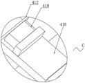
A connecting block 418 is fixedly mounted at the lower end of the connecting box 42 described with reference to fig. 9 to 10, a fifth air bag 419 is disposed at the upper end of the connecting block 418, a magnet 4112 is movably connected inside the connecting block 418 through a third elastic column 4111, and the fifth air bag 419 is connected to the inside of the connecting block 418 through a second connecting tube 4110 at a position close to the upper end.
Through setting up connecting block 418, when the movable block 46 to the in-process that is close to the blade direction and removes, drive extrusion piece 412 and extrude fifth gasbag 419, the extrusion force makes the inside gas of fifth gasbag 419 extrude magnet 4112 through the inside that second connecting pipe 4110 got into connecting block 418, the extrusion force makes magnet 4112 overcome the elasticity of third elasticity post 4111 and removes to the direction that is close to 2 blades of ink scraping knife, because ink scraping knife 2 is made by the material that has magnetism, thereby when piece 49 of polishing is polished ink scraping knife 2, the magnetic force that magnet 4112 produced can carry out the adsorption treatment to the sweeps that grinds the in-process and produce, reduce the sweeps and drop to the china ink in, influence the problem of china ink normal use.
Referring to fig. 10, a collecting box 4113 is disposed at a lower end of the connecting block 418, and a scraping plate 4114 is fixedly mounted on an inner surface of the collecting box 4113.
When finishing the extrusion piece 412 when getting back to the normal position of polishing, third elasticity post 4111 resumes elastic deformation's elasticity and drives magnet 4112 and get back to the normal position, get back to the in-process of normal position at magnet 4112, the gathering of absorbent sweeps is in one place on scraper 4114 messenger magnet 4112, magnet 4112 reduces the sweeps adsorption affinity of outside this moment, part sweeps drops to inside collecting box 4113, and then reduce the volume of adnexed sweeps on magnet 4112, guarantee magnet 4112's working effect, the staff only need in time to collect the inside sweeps of box 4113 clear up can, all clear up the sweeps on magnet 4112 after need not polishing at every turn.
Referring to fig. 10, the distance between the magnet 4112 and the doctor blade 2 is 2cm to 5cm.
By setting the distance between the magnet 4112 and the doctor blade 2 to be 2cm-5cm, the problem that the normal use of the magnet 4112 is affected by the fact that the distance between the magnet 4112 and the doctor blade 2 is too small, ink can be attached to the adsorption surface of the magnet 4112 in a large amount, and the problem that the too large adsorption force between the magnet 4112 and the doctor blade 2 is reduced is solved, so that the normal work of the magnet 4112 is ensured.
The above examples are only intended to illustrate the technical solution of the present invention, and not to limit it; although the present invention has been described in detail with reference to the foregoing embodiments, it should be understood by those of ordinary skill in the art that: the technical solutions described in the foregoing embodiments may still be modified, or some technical features may be equivalently replaced; and the modifications or the substitutions do not cause the essence of the corresponding technical solutions to depart from the scope of the technical solutions of the embodiments of the present invention.
Claims (8)
1. A laminated flexographic printing press comprising: printing machine body (1), ink scraping blade (2), printing roller (3), its characterized in that still includes: the polishing mechanism (4) is arranged inside the printer body (1) and close to the upper end of the ink scraping blade (2), and the polishing mechanism (4) is used for polishing the ink scraping blade (2) when the ink scraping blade (2) is abraded and needs to be polished;
grinding mechanism (4) is including connecting box (42) that cylinder (41) is connected through the one side surface of printer body (1), the inside of connecting box (42) is provided with driving piece (44), the interior bottom surface fixed mounting of connecting box (42) has mounting box (4115), driving piece (44) are connected with mounting box (4115) through first connecting pipe (43), the inside of mounting box (4115) has movable block (46) through first elasticity post (45) sliding connection, the lower extreme of movable block (46) is connected with grinding piece (49) through second elasticity post (47), elastic layer (48), the one end of movable block (46) is provided with control piece (40), driving piece (44) are used for driving movable block (46) to drive the blade removal of grinding piece (49) to doctor blade (2), control piece (40) make grinding piece (49) better laminate when doctor blade (2) need polish, cylinder (41) make cutting piece (49) can be along the doctor blade direction on grinding doctor blade (2) the outer surface of connecting box (4115) along the direction sliding connection box (4115) one side of fixed mounting box (411) is close to the installation of fixing block (411).
2. The laminated flexographic printing machine according to claim 1, characterized in that the driving member (44) comprises a first air bag (411) and a second air bag (442) which are sequentially arranged on the outer surfaces of two sides of the connecting box (42), a third air bag (445) is fixedly installed inside the connecting box (42), a clamping block (446) is fixedly installed at the position, close to the third air bag (445), of the top surface of the connecting box (42), a squeezing plate (444) is movably connected to the outer side, close to the third air bag (445), of the inside of the connecting box (42), the connecting box (42) is connected with the second air bag (442) through a third connecting pipe (443), and the connecting box (42) is connected with the first air bag (441) through a connecting hole (447).
3. The laminated flexographic printing press according to claim 1, wherein the control member (40) comprises a pressing rod (404) fixedly mounted on the bottom surface of the mounting box (4115), a connection port (401) is formed through one end of the movable block (46) near the pressing rod (404), a sealing block (402) is elastically connected to one end of the movable block (46) near the upper end of the connection port (401), a through hole (403) is formed in one side of the inner portion of the movable block (46) near the connection port (401), and one end of the through hole (403) extends to a position near the second elastic column (47).
4. The laminated flexographic printing press according to claim 1, characterized in that a cleaning blade (416) is attached to the outer surface of the cleaning block (411) by means of a moving member, said cleaning blade (416) being elastically connected to the cleaning block (411) by means of an elastic member (417).
5. The laminated flexographic printing press as recited in claim 4, characterized in that the moving member comprises a pressing block (412) fixedly mounted on an upper end of the movable block (46), the pressing block (412) extends to an upper end position of the cleaning block (411), a fourth air bag (413) and a mounting block (414) are sequentially connected to the upper end of the cleaning block (411) at a position close to the pressing block (412), and the fourth air bag (413) is connected with the cleaning sheet (416) through a corrugated pipe (415).
6. The laminated flexographic printing press according to claim 1, characterized in that a connecting block (418) is fixedly mounted at a lower end of the connecting box (42), a fifth air bag (419) is disposed at an upper end of the connecting block (418), a magnet (4112) is movably connected inside the connecting block (418) through a third elastic column (4111), and the fifth air bag (419) is communicated with the inside of the connecting block (418) near the upper end through a second connecting tube (4110).
7. The laminated flexographic printing press according to claim 6, characterized in that a collecting box (4113) is arranged at a lower end of the connecting block (418), and a squeegee (4114) is fixedly mounted on an inner surface of the collecting box (4113).
8. The laminated flexographic printing press according to claim 6, characterized in that the distance between the magnet (4112) and the doctor blade (2) is comprised between 2cm and 5cm.
Priority Applications (1)
| Application Number | Priority Date | Filing Date | Title |
|---|---|---|---|
| CN202211209350.XA CN115401988B (en) | 2022-09-30 | 2022-09-30 | Stacked flexographic printing machine |
Applications Claiming Priority (1)
| Application Number | Priority Date | Filing Date | Title |
|---|---|---|---|
| CN202211209350.XA CN115401988B (en) | 2022-09-30 | 2022-09-30 | Stacked flexographic printing machine |
Publications (2)
| Publication Number | Publication Date |
|---|---|
| CN115401988A true CN115401988A (en) | 2022-11-29 |
| CN115401988B CN115401988B (en) | 2023-05-16 |
Family
ID=84168432
Family Applications (1)
| Application Number | Title | Priority Date | Filing Date |
|---|---|---|---|
| CN202211209350.XA Active CN115401988B (en) | 2022-09-30 | 2022-09-30 | Stacked flexographic printing machine |
Country Status (1)
| Country | Link |
|---|---|
| CN (1) | CN115401988B (en) |
Citations (19)
| Publication number | Priority date | Publication date | Assignee | Title |
|---|---|---|---|---|
| DE19624971A1 (en) * | 1996-06-22 | 1998-01-02 | Hubert Keller | Printing machine doctoring unit |
| TW409310B (en) * | 1999-04-01 | 2000-10-21 | Tama Kagaku Kogyo Kk | Method and apparatus of supplying polishing agent for the manufacture of semiconductors |
| JP2008221448A (en) * | 2007-03-16 | 2008-09-25 | Dainippon Printing Co Ltd | Doctor blade polishing apparatus and doctor blade polishing method |
| CN102407660A (en) * | 2010-09-26 | 2012-04-11 | Jpe株式会社 | Ink pot device |
| CN208179131U (en) * | 2018-03-12 | 2018-12-04 | 天津卓越科技有限公司 | A kind of novel machine tool knife grinding equipment |
| CN110001185A (en) * | 2019-04-08 | 2019-07-12 | 黄焕生 | A kind of printing equipment of flexible printing machine |
| CN212578179U (en) * | 2020-06-16 | 2021-02-23 | 昆山达利祥精密五金科技有限公司 | Knife sharpener of gravure printing machine scraper |
| CN112519414A (en) * | 2020-12-02 | 2021-03-19 | 嘉兴亦盼家电有限公司 | Relief printing machine different diameter bearer surface cleaning device |
| CN213108679U (en) * | 2020-07-28 | 2021-05-04 | 江阴同澄机械有限公司 | Printing roller ink scraper of printing composite all-in-one machine |
| CN113458850A (en) * | 2021-05-28 | 2021-10-01 | 周云娟 | Turning lathe |
| CN214395867U (en) * | 2020-12-29 | 2021-10-15 | 青岛康彩塑料包装制品有限公司 | An easy-to-clean gravure printing mechanism |
| CN214563852U (en) * | 2021-03-15 | 2021-11-02 | 杭州明日软包装有限公司 | Ink scraping device for printing machine |
| CN113895145A (en) * | 2021-10-27 | 2022-01-07 | 郑月平 | Printing ink printing system |
| CN114012589A (en) * | 2021-11-25 | 2022-02-08 | 徐州锌浩精密机械科技有限公司 | Bearing inner ring polishing device based on gas medium filling and use method thereof |
| CN216069240U (en) * | 2021-07-23 | 2022-03-18 | 宁夏成峰包装印刷有限公司 | Inking device of high-speed printing machine |
| CN114434961A (en) * | 2022-02-17 | 2022-05-06 | 舒一苒 | Printing machine roller |
| CN114560629A (en) * | 2022-03-17 | 2022-05-31 | 李治开 | Glass fiber precursor production facility |
| CN216683749U (en) * | 2021-12-15 | 2022-06-07 | 深圳市辉宇网印机械设备有限公司 | Automatic pressure detection, compensation and regulation system used during scraper printing |
| CN217170101U (en) * | 2021-11-30 | 2022-08-12 | 东莞市炜天智能设备有限公司 | Printing device with water-cooling curing assembly |
-
2022
- 2022-09-30 CN CN202211209350.XA patent/CN115401988B/en active Active
Patent Citations (19)
| Publication number | Priority date | Publication date | Assignee | Title |
|---|---|---|---|---|
| DE19624971A1 (en) * | 1996-06-22 | 1998-01-02 | Hubert Keller | Printing machine doctoring unit |
| TW409310B (en) * | 1999-04-01 | 2000-10-21 | Tama Kagaku Kogyo Kk | Method and apparatus of supplying polishing agent for the manufacture of semiconductors |
| JP2008221448A (en) * | 2007-03-16 | 2008-09-25 | Dainippon Printing Co Ltd | Doctor blade polishing apparatus and doctor blade polishing method |
| CN102407660A (en) * | 2010-09-26 | 2012-04-11 | Jpe株式会社 | Ink pot device |
| CN208179131U (en) * | 2018-03-12 | 2018-12-04 | 天津卓越科技有限公司 | A kind of novel machine tool knife grinding equipment |
| CN110001185A (en) * | 2019-04-08 | 2019-07-12 | 黄焕生 | A kind of printing equipment of flexible printing machine |
| CN212578179U (en) * | 2020-06-16 | 2021-02-23 | 昆山达利祥精密五金科技有限公司 | Knife sharpener of gravure printing machine scraper |
| CN213108679U (en) * | 2020-07-28 | 2021-05-04 | 江阴同澄机械有限公司 | Printing roller ink scraper of printing composite all-in-one machine |
| CN112519414A (en) * | 2020-12-02 | 2021-03-19 | 嘉兴亦盼家电有限公司 | Relief printing machine different diameter bearer surface cleaning device |
| CN214395867U (en) * | 2020-12-29 | 2021-10-15 | 青岛康彩塑料包装制品有限公司 | An easy-to-clean gravure printing mechanism |
| CN214563852U (en) * | 2021-03-15 | 2021-11-02 | 杭州明日软包装有限公司 | Ink scraping device for printing machine |
| CN113458850A (en) * | 2021-05-28 | 2021-10-01 | 周云娟 | Turning lathe |
| CN216069240U (en) * | 2021-07-23 | 2022-03-18 | 宁夏成峰包装印刷有限公司 | Inking device of high-speed printing machine |
| CN113895145A (en) * | 2021-10-27 | 2022-01-07 | 郑月平 | Printing ink printing system |
| CN114012589A (en) * | 2021-11-25 | 2022-02-08 | 徐州锌浩精密机械科技有限公司 | Bearing inner ring polishing device based on gas medium filling and use method thereof |
| CN217170101U (en) * | 2021-11-30 | 2022-08-12 | 东莞市炜天智能设备有限公司 | Printing device with water-cooling curing assembly |
| CN216683749U (en) * | 2021-12-15 | 2022-06-07 | 深圳市辉宇网印机械设备有限公司 | Automatic pressure detection, compensation and regulation system used during scraper printing |
| CN114434961A (en) * | 2022-02-17 | 2022-05-06 | 舒一苒 | Printing machine roller |
| CN114560629A (en) * | 2022-03-17 | 2022-05-31 | 李治开 | Glass fiber precursor production facility |
Also Published As
| Publication number | Publication date |
|---|---|
| CN115401988B (en) | 2023-05-16 |
Similar Documents
| Publication | Publication Date | Title |
|---|---|---|
| CN106079852B (en) | A kind of intaglio press doctor device | |
| CN201881623U (en) | Gravure-flexography combined playing card printing system | |
| CN115401988A (en) | Laminated flexible printing press | |
| CN111377282A (en) | Multi-station paper printing production device | |
| CN214688471U (en) | Ink smearing device for lens screen printing machine | |
| CN218857488U (en) | Calendering mechanism for calender | |
| CN114344968A (en) | Environment-friendly diaphragm filter press | |
| CN221275967U (en) | Full-automatic high-efficiency plate cleaning machine | |
| CN113135012A (en) | Manufacturing and processing technology of sodium bentonite waterproof blanket | |
| CN215148001U (en) | Leveling and polishing device for sheet laser micropore screen | |
| CN117124128A (en) | A plate processing device | |
| CN217250136U (en) | Rubber coating device is used in window wrap production | |
| CN219686831U (en) | Efficient scraper replacing device of screen printer | |
| CN212179497U (en) | Sheet cleaning and squeezing device | |
| CN217753194U (en) | Printing roller ink scraper for printing production | |
| CN217459737U (en) | Water jet loom with high vacuum water absorption performance | |
| CN212942322U (en) | Porous support material surface immersion liquid device is used in inorganic complex film production | |
| CN214137808U (en) | Water-based ink printing plastic edge sealing strip equipment | |
| CN223173734U (en) | Efficient lamination device for wear-resistant and anti-fouling automotive interior artificial leather | |
| CN223045390U (en) | Corner window ink absorber | |
| CN221581012U (en) | Trepanning, plastering and sealing device | |
| CN112157990A (en) | Movable printing machine with cleaning function | |
| CN219853783U (en) | Carbon fiber composite polishing and cleaning device | |
| CN221608450U (en) | Cloth cutting machine | |
| CN220716541U (en) | Roller core surface gluing device |
Legal Events
| Date | Code | Title | Description |
|---|---|---|---|
| PB01 | Publication | ||
| PB01 | Publication | ||
| SE01 | Entry into force of request for substantive examination | ||
| SE01 | Entry into force of request for substantive examination | ||
| GR01 | Patent grant | ||
| GR01 | Patent grant |