CN115372345A - Automatic in vitro diagnosis and examination device - Google Patents
Automatic in vitro diagnosis and examination device Download PDFInfo
- Publication number
- CN115372345A CN115372345A CN202210554937.8A CN202210554937A CN115372345A CN 115372345 A CN115372345 A CN 115372345A CN 202210554937 A CN202210554937 A CN 202210554937A CN 115372345 A CN115372345 A CN 115372345A
- Authority
- CN
- China
- Prior art keywords
- cuvette
- test tube
- vitro diagnostic
- driving
- driving part
- Prior art date
- Legal status (The legal status is an assumption and is not a legal conclusion. Google has not performed a legal analysis and makes no representation as to the accuracy of the status listed.)
- Pending
Links
Images


Classifications
-
- G—PHYSICS
- G01—MEASURING; TESTING
- G01N—INVESTIGATING OR ANALYSING MATERIALS BY DETERMINING THEIR CHEMICAL OR PHYSICAL PROPERTIES
- G01N35/00—Automatic analysis not limited to methods or materials provided for in any single one of groups G01N1/00 - G01N33/00; Handling materials therefor
- G01N35/10—Devices for transferring samples or any liquids to, in, or from, the analysis apparatus, e.g. suction devices, injection devices
- G01N35/1081—Devices for transferring samples or any liquids to, in, or from, the analysis apparatus, e.g. suction devices, injection devices characterised by the means for relatively moving the transfer device and the containers in an horizontal plane
-
- G—PHYSICS
- G01—MEASURING; TESTING
- G01N—INVESTIGATING OR ANALYSING MATERIALS BY DETERMINING THEIR CHEMICAL OR PHYSICAL PROPERTIES
- G01N35/00—Automatic analysis not limited to methods or materials provided for in any single one of groups G01N1/00 - G01N33/00; Handling materials therefor
- G01N35/00029—Automatic analysis not limited to methods or materials provided for in any single one of groups G01N1/00 - G01N33/00; Handling materials therefor provided with flat sample substrates, e.g. slides
-
- G—PHYSICS
- G01—MEASURING; TESTING
- G01N—INVESTIGATING OR ANALYSING MATERIALS BY DETERMINING THEIR CHEMICAL OR PHYSICAL PROPERTIES
- G01N1/00—Sampling; Preparing specimens for investigation
- G01N1/02—Devices for withdrawing samples
- G01N1/10—Devices for withdrawing samples in the liquid or fluent state
- G01N1/14—Suction devices, e.g. pumps; Ejector devices
-
- G—PHYSICS
- G01—MEASURING; TESTING
- G01N—INVESTIGATING OR ANALYSING MATERIALS BY DETERMINING THEIR CHEMICAL OR PHYSICAL PROPERTIES
- G01N1/00—Sampling; Preparing specimens for investigation
- G01N1/28—Preparing specimens for investigation including physical details of (bio-)chemical methods covered elsewhere, e.g. G01N33/50, C12Q
- G01N1/38—Diluting, dispersing or mixing samples
-
- G—PHYSICS
- G01—MEASURING; TESTING
- G01N—INVESTIGATING OR ANALYSING MATERIALS BY DETERMINING THEIR CHEMICAL OR PHYSICAL PROPERTIES
- G01N21/00—Investigating or analysing materials by the use of optical means, i.e. using sub-millimetre waves, infrared, visible or ultraviolet light
- G01N21/01—Arrangements or apparatus for facilitating the optical investigation
- G01N21/03—Cuvette constructions
-
- G—PHYSICS
- G01—MEASURING; TESTING
- G01N—INVESTIGATING OR ANALYSING MATERIALS BY DETERMINING THEIR CHEMICAL OR PHYSICAL PROPERTIES
- G01N21/00—Investigating or analysing materials by the use of optical means, i.e. using sub-millimetre waves, infrared, visible or ultraviolet light
- G01N21/75—Systems in which material is subjected to a chemical reaction, the progress or the result of the reaction being investigated
- G01N21/77—Systems in which material is subjected to a chemical reaction, the progress or the result of the reaction being investigated by observing the effect on a chemical indicator
- G01N21/78—Systems in which material is subjected to a chemical reaction, the progress or the result of the reaction being investigated by observing the effect on a chemical indicator producing a change of colour
-
- G—PHYSICS
- G01—MEASURING; TESTING
- G01N—INVESTIGATING OR ANALYSING MATERIALS BY DETERMINING THEIR CHEMICAL OR PHYSICAL PROPERTIES
- G01N33/00—Investigating or analysing materials by specific methods not covered by groups G01N1/00 - G01N31/00
- G01N33/48—Biological material, e.g. blood, urine; Haemocytometers
- G01N33/50—Chemical analysis of biological material, e.g. blood, urine; Testing involving biospecific ligand binding methods; Immunological testing
- G01N33/52—Use of compounds or compositions for colorimetric, spectrophotometric or fluorometric investigation, e.g. use of reagent paper and including single- and multilayer analytical elements
- G01N33/521—Single-layer analytical elements
-
- G—PHYSICS
- G01—MEASURING; TESTING
- G01N—INVESTIGATING OR ANALYSING MATERIALS BY DETERMINING THEIR CHEMICAL OR PHYSICAL PROPERTIES
- G01N35/00—Automatic analysis not limited to methods or materials provided for in any single one of groups G01N1/00 - G01N33/00; Handling materials therefor
- G01N35/02—Automatic analysis not limited to methods or materials provided for in any single one of groups G01N1/00 - G01N33/00; Handling materials therefor using a plurality of sample containers moved by a conveyor system past one or more treatment or analysis stations
- G01N35/026—Automatic analysis not limited to methods or materials provided for in any single one of groups G01N1/00 - G01N33/00; Handling materials therefor using a plurality of sample containers moved by a conveyor system past one or more treatment or analysis stations having blocks or racks of reaction cells or cuvettes
-
- G—PHYSICS
- G01—MEASURING; TESTING
- G01N—INVESTIGATING OR ANALYSING MATERIALS BY DETERMINING THEIR CHEMICAL OR PHYSICAL PROPERTIES
- G01N35/00—Automatic analysis not limited to methods or materials provided for in any single one of groups G01N1/00 - G01N33/00; Handling materials therefor
- G01N35/02—Automatic analysis not limited to methods or materials provided for in any single one of groups G01N1/00 - G01N33/00; Handling materials therefor using a plurality of sample containers moved by a conveyor system past one or more treatment or analysis stations
- G01N35/04—Details of the conveyor system
-
- G—PHYSICS
- G01—MEASURING; TESTING
- G01N—INVESTIGATING OR ANALYSING MATERIALS BY DETERMINING THEIR CHEMICAL OR PHYSICAL PROPERTIES
- G01N35/00—Automatic analysis not limited to methods or materials provided for in any single one of groups G01N1/00 - G01N33/00; Handling materials therefor
- G01N35/10—Devices for transferring samples or any liquids to, in, or from, the analysis apparatus, e.g. suction devices, injection devices
- G01N35/1002—Reagent dispensers
-
- G—PHYSICS
- G01—MEASURING; TESTING
- G01N—INVESTIGATING OR ANALYSING MATERIALS BY DETERMINING THEIR CHEMICAL OR PHYSICAL PROPERTIES
- G01N35/00—Automatic analysis not limited to methods or materials provided for in any single one of groups G01N1/00 - G01N33/00; Handling materials therefor
- G01N35/10—Devices for transferring samples or any liquids to, in, or from, the analysis apparatus, e.g. suction devices, injection devices
- G01N35/1079—Devices for transferring samples or any liquids to, in, or from, the analysis apparatus, e.g. suction devices, injection devices with means for piercing stoppers or septums
-
- G—PHYSICS
- G01—MEASURING; TESTING
- G01N—INVESTIGATING OR ANALYSING MATERIALS BY DETERMINING THEIR CHEMICAL OR PHYSICAL PROPERTIES
- G01N35/00—Automatic analysis not limited to methods or materials provided for in any single one of groups G01N1/00 - G01N33/00; Handling materials therefor
- G01N35/10—Devices for transferring samples or any liquids to, in, or from, the analysis apparatus, e.g. suction devices, injection devices
- G01N35/1081—Devices for transferring samples or any liquids to, in, or from, the analysis apparatus, e.g. suction devices, injection devices characterised by the means for relatively moving the transfer device and the containers in an horizontal plane
- G01N35/1083—Devices for transferring samples or any liquids to, in, or from, the analysis apparatus, e.g. suction devices, injection devices characterised by the means for relatively moving the transfer device and the containers in an horizontal plane with one horizontal degree of freedom
-
- G—PHYSICS
- G01—MEASURING; TESTING
- G01N—INVESTIGATING OR ANALYSING MATERIALS BY DETERMINING THEIR CHEMICAL OR PHYSICAL PROPERTIES
- G01N21/00—Investigating or analysing materials by the use of optical means, i.e. using sub-millimetre waves, infrared, visible or ultraviolet light
- G01N21/75—Systems in which material is subjected to a chemical reaction, the progress or the result of the reaction being investigated
- G01N21/77—Systems in which material is subjected to a chemical reaction, the progress or the result of the reaction being investigated by observing the effect on a chemical indicator
- G01N2021/7756—Sensor type
- G01N2021/7759—Dipstick; Test strip
-
- G—PHYSICS
- G01—MEASURING; TESTING
- G01N—INVESTIGATING OR ANALYSING MATERIALS BY DETERMINING THEIR CHEMICAL OR PHYSICAL PROPERTIES
- G01N35/00—Automatic analysis not limited to methods or materials provided for in any single one of groups G01N1/00 - G01N33/00; Handling materials therefor
- G01N35/00029—Automatic analysis not limited to methods or materials provided for in any single one of groups G01N1/00 - G01N33/00; Handling materials therefor provided with flat sample substrates, e.g. slides
- G01N2035/00099—Characterised by type of test elements
- G01N2035/00108—Test strips, e.g. paper
-
- G—PHYSICS
- G01—MEASURING; TESTING
- G01N—INVESTIGATING OR ANALYSING MATERIALS BY DETERMINING THEIR CHEMICAL OR PHYSICAL PROPERTIES
- G01N35/00—Automatic analysis not limited to methods or materials provided for in any single one of groups G01N1/00 - G01N33/00; Handling materials therefor
- G01N2035/00465—Separating and mixing arrangements
- G01N2035/00524—Mixing by agitating sample carrier
-
- G—PHYSICS
- G01—MEASURING; TESTING
- G01N—INVESTIGATING OR ANALYSING MATERIALS BY DETERMINING THEIR CHEMICAL OR PHYSICAL PROPERTIES
- G01N35/00—Automatic analysis not limited to methods or materials provided for in any single one of groups G01N1/00 - G01N33/00; Handling materials therefor
- G01N2035/00465—Separating and mixing arrangements
- G01N2035/00534—Mixing by a special element, e.g. stirrer
-
- G—PHYSICS
- G01—MEASURING; TESTING
- G01N—INVESTIGATING OR ANALYSING MATERIALS BY DETERMINING THEIR CHEMICAL OR PHYSICAL PROPERTIES
- G01N35/00—Automatic analysis not limited to methods or materials provided for in any single one of groups G01N1/00 - G01N33/00; Handling materials therefor
- G01N35/00584—Control arrangements for automatic analysers
- G01N35/00722—Communications; Identification
- G01N35/00732—Identification of carriers, materials or components in automatic analysers
- G01N2035/00742—Type of codes
- G01N2035/00752—Type of codes bar codes
-
- G—PHYSICS
- G01—MEASURING; TESTING
- G01N—INVESTIGATING OR ANALYSING MATERIALS BY DETERMINING THEIR CHEMICAL OR PHYSICAL PROPERTIES
- G01N35/00—Automatic analysis not limited to methods or materials provided for in any single one of groups G01N1/00 - G01N33/00; Handling materials therefor
- G01N35/00584—Control arrangements for automatic analysers
- G01N35/00722—Communications; Identification
- G01N35/00732—Identification of carriers, materials or components in automatic analysers
- G01N2035/00821—Identification of carriers, materials or components in automatic analysers nature of coded information
- G01N2035/00831—Identification of carriers, materials or components in automatic analysers nature of coded information identification of the sample, e.g. patient identity, place of sampling
-
- G—PHYSICS
- G01—MEASURING; TESTING
- G01N—INVESTIGATING OR ANALYSING MATERIALS BY DETERMINING THEIR CHEMICAL OR PHYSICAL PROPERTIES
- G01N35/00—Automatic analysis not limited to methods or materials provided for in any single one of groups G01N1/00 - G01N33/00; Handling materials therefor
- G01N35/02—Automatic analysis not limited to methods or materials provided for in any single one of groups G01N1/00 - G01N33/00; Handling materials therefor using a plurality of sample containers moved by a conveyor system past one or more treatment or analysis stations
- G01N35/04—Details of the conveyor system
- G01N2035/0401—Sample carriers, cuvettes or reaction vessels
- G01N2035/0412—Block or rack elements with a single row of samples
- G01N2035/0413—Block or rack elements with a single row of samples moving in one dimension
-
- G—PHYSICS
- G01—MEASURING; TESTING
- G01N—INVESTIGATING OR ANALYSING MATERIALS BY DETERMINING THEIR CHEMICAL OR PHYSICAL PROPERTIES
- G01N35/00—Automatic analysis not limited to methods or materials provided for in any single one of groups G01N1/00 - G01N33/00; Handling materials therefor
- G01N35/02—Automatic analysis not limited to methods or materials provided for in any single one of groups G01N1/00 - G01N33/00; Handling materials therefor using a plurality of sample containers moved by a conveyor system past one or more treatment or analysis stations
- G01N35/04—Details of the conveyor system
- G01N2035/0401—Sample carriers, cuvettes or reaction vessels
- G01N2035/0429—Sample carriers adapted for special purposes
- G01N2035/0436—Sample carriers adapted for special purposes with pre-packaged reagents, i.e. test-packs
-
- G—PHYSICS
- G01—MEASURING; TESTING
- G01N—INVESTIGATING OR ANALYSING MATERIALS BY DETERMINING THEIR CHEMICAL OR PHYSICAL PROPERTIES
- G01N35/00—Automatic analysis not limited to methods or materials provided for in any single one of groups G01N1/00 - G01N33/00; Handling materials therefor
- G01N35/10—Devices for transferring samples or any liquids to, in, or from, the analysis apparatus, e.g. suction devices, injection devices
- G01N2035/1027—General features of the devices
- G01N2035/103—General features of the devices using disposable tips
-
- G—PHYSICS
- G01—MEASURING; TESTING
- G01N—INVESTIGATING OR ANALYSING MATERIALS BY DETERMINING THEIR CHEMICAL OR PHYSICAL PROPERTIES
- G01N21/00—Investigating or analysing materials by the use of optical means, i.e. using sub-millimetre waves, infrared, visible or ultraviolet light
- G01N21/84—Systems specially adapted for particular applications
- G01N21/8483—Investigating reagent band
Landscapes
- Health & Medical Sciences (AREA)
- Life Sciences & Earth Sciences (AREA)
- Chemical & Material Sciences (AREA)
- Immunology (AREA)
- Physics & Mathematics (AREA)
- Biochemistry (AREA)
- General Health & Medical Sciences (AREA)
- General Physics & Mathematics (AREA)
- Analytical Chemistry (AREA)
- Pathology (AREA)
- Engineering & Computer Science (AREA)
- Chemical Kinetics & Catalysis (AREA)
- Hematology (AREA)
- Molecular Biology (AREA)
- Urology & Nephrology (AREA)
- Biomedical Technology (AREA)
- Plasma & Fusion (AREA)
- Cell Biology (AREA)
- Microbiology (AREA)
- Biotechnology (AREA)
- Hydrology & Water Resources (AREA)
- Food Science & Technology (AREA)
- Medicinal Chemistry (AREA)
- Automatic Analysis And Handling Materials Therefor (AREA)
Abstract
本发明涉及一种能够对血液、尿液等生物学样本中包括的特定成分自动执行包括预处理过程在内的一系列检查过程的自动体外诊断检查装置。本发明的所述装置包括:基架;比色皿托盘,安置有容纳并排布置的多个比色皿的比色皿架,并且在所述基架上可前后移动;试管托盘,安置有容纳包含样本的多个试管的试管架,并且在所述基架上可前后移动;以及采集操作部,相对于所述基架可左右移动地设置,并且将容纳在所述试管中的样本与试剂混合,并将混合液滴落到设置在所述比色皿中的分析条上。
The present invention relates to an automatic in-vitro diagnostic inspection device capable of automatically performing a series of inspection processes including a pretreatment process on specific components included in biological samples such as blood and urine. The device of the present invention comprises: a base frame; a cuvette tray, which is provided with a cuvette rack for accommodating a plurality of cuvettes arranged side by side, and can move back and forth on the base frame; a test tube rack containing a plurality of test tubes of samples, and movable back and forth on the base rack; Mix and drop the mixture onto the assay strip set in the cuvette.
Description
技术领域technical field
本发明涉及一种自动体外诊断检查装置,其能够对血液、尿液等生物学样本中包括的特定成分自动执行包括预处理过程在内的一系列检查过程。The present invention relates to an automatic in vitro diagnostic inspection device, which can automatically perform a series of inspection procedures including pretreatment procedures on specific components included in biological samples such as blood and urine.
背景技术Background technique
近年来,随着人与动物的感染、新型流感的流行和其他各种感染的增加,通过分析将从人或动物采集的血液、尿液等生物学样本与预定试剂进行反应后发生的变化来检查有无疾病、疾病状态的需求正在进一步增加。In recent years, with the increase of infections between humans and animals, the prevalence of new types of influenza, and various other infections, it is possible to analyze the changes that occur when biological samples such as blood and urine collected from humans or animals are reacted with predetermined reagents. The need to check for the presence of diseases and disease states is further increasing.
在这种试样的检查过程中,使试样和用于检查试样的试剂不受外界因素的影响,并且每次使用准确的量对于获得可重现性的准确结果是非常重要的。在检查过程中,由于试样和试剂可能会暴露于外部,因此需要有效防止由于试样和试剂的暴露而造成的污染,并通过使用准确的量来保证检查的准确性。During the inspection of such samples, it is very important to keep the samples and the reagents used for the inspection of the samples free from external factors, and to use an accurate amount each time to obtain accurate results with reproducibility. During the inspection process, since the samples and reagents may be exposed to the outside, it is necessary to effectively prevent contamination due to the exposure of the samples and reagents, and ensure the accuracy of the inspection by using accurate amounts.
此外,在试剂与试样反应后,需要通过在一个集成系统中准确快速地执行用于检测和读取/分析反应生成物的检查来减少检查时间和检查成本,以减少整个检查中包括的步骤和投入成本。In addition, after the reagent reacts with the sample, it is necessary to reduce the inspection time and inspection cost by accurately and quickly performing the inspection for detecting and reading/analyzing the reaction product in one integrated system to reduce the number of steps included in the entire inspection and input costs.
此外,由于用于这种检查的传统的体外诊断检查装置在每次诊断检查中仅使用一个诊断试剂盒,因此在快速执行目标对象的检查、分析和诊断方面存在限制。Furthermore, since the conventional in vitro diagnostic test apparatus for such examination uses only one diagnostic kit per diagnostic test, there are limitations in rapidly performing examination, analysis, and diagnosis of a target object.
现有技术文献prior art literature
专利文献patent documents
(专利文献1)授权专利公报第10-1811786号(公告日期:2017.12.22)(Patent Document 1) Authorized Patent Publication No. 10-1811786 (Date of Publication: 2017.12.22)
发明内容Contents of the invention
(一)要解决的技术问题(1) Technical problems to be solved
本发明用于改进现有技术的问题,旨在提供一种自动体外诊断检查装置,其能够自动化包括从样本采集到试样预处理在内的一系列检查过程,并且可以对单个样本同时执行各种类型的检查或在一次检查过程中同时对大量样本执行快速准确的处理。The present invention is used to improve the problems of the prior art, and aims to provide an automatic in vitro diagnostic inspection device, which can automate a series of inspection processes from sample collection to sample pretreatment, and can perform various procedures on a single sample at the same time. different types of examinations or perform fast and accurate processing of a large number of samples simultaneously during a single examination.
(二)技术方案(2) Technical solutions
用于实现上述目的的根据本发明的自动体外诊断检查装置,包括:基架;比色皿托盘,在所述基架上可以前后移动,并且安置有容纳彼此并排布置的多个比色皿的比色皿架,每个比色皿包括至少一个开放室、试剂室、吸头和包括分析条的盒并构成一个单位组;第一驱动部,用于前后移动所述比色皿托盘;试管托盘,安置有容纳包含样本的多个试管的试管架,并在所述基架上可平行于所述比色皿托盘的移动方向前后移动;第二驱动部,用于前后移动所述试管托盘;采集操作部,可相对于所述基架左右移动地设置,并且采集容纳在所述试管中的样本以将其与试剂混合,并将混合液滴落到设置在所述比色皿中的分析条上;第三驱动部,用于左右移动所述采集操作部;光学分析部,设置在所述采集操作部的后端,并可相对于所述基架左右移动地设置,并且光学分析所述比色皿的分析条;以及第四驱动部,用于左右移动所述光学分析部。The automatic in-vitro diagnostic inspection device according to the present invention for achieving the above-mentioned purpose comprises: a base frame; A cuvette holder, each cuvette comprising at least one open chamber, a reagent chamber, a tip, and a box including an assay strip and constituting a unit set; a first driving portion for moving said cuvette tray back and forth; test tubes a tray, a test tube rack for accommodating a plurality of test tubes containing samples is arranged, and can move back and forth on the base frame parallel to the moving direction of the cuvette tray; a second driving part is used for moving the test tube tray back and forth the collection operation part is provided to move left and right relative to the base frame, and collects the sample contained in the test tube to mix it with the reagent, and drops the mixed solution to the cuvette provided in the cuvette; on the analysis bar; the third driving part is used to move the collection operation part left and right; the optical analysis part is arranged at the rear end of the collection operation part and can be moved left and right relative to the base frame, and the optical analysis part an analysis bar of the cuvette; and a fourth drive unit for moving the optical analysis unit left and right.
(三)有益效果(3) Beneficial effects
根据本发明的自动体外诊断检查装置包括:比色皿托盘,安置有容纳并排布置的多个比色皿的比色皿架,以在装置中可前后移动;试管托盘,安置有容纳多个试管的试管架,以在装置中可前后移动;以及混合部,用于混合容纳在试管中的样本,由此,样本以试管为单位直接投入到装置中,并且自动执行包括试样的预处理过程在内的一系列检查工作,因此在最小化由于样本暴露于外部而导致的污染的同时,提高检查的准确性和重现性。The automatic in vitro diagnostic inspection device according to the present invention comprises: a cuvette tray, a cuvette rack for accommodating a plurality of cuvettes arranged side by side, so as to be movable back and forth in the device; a test tube tray, for accommodating a plurality of cuvettes a test tube rack for moving back and forth in the device; and a mixing section for mixing the samples contained in the test tubes, whereby the samples are directly put into the device in units of test tubes, and the pretreatment process including the samples is automatically performed Including a series of inspection work, thus improving the accuracy and reproducibility of the inspection while minimizing the contamination caused by the exposure of the sample to the outside.
此外,在本发明中,将容纳有并排布置的多个比色皿的比色皿架和容纳有多个无盖试管的试管架直接投人到装置中执行检查,从而可以在一台检查装置中同时对大量样本执行相同诊断(分析)项目,或对一个样本同时执行多种诊断(分析)项目。In addition, in the present invention, the cuvette rack accommodating a plurality of cuvettes arranged side by side and the test tube rack accommodating a plurality of test tubes without caps are directly put into the device to perform inspection, so that the inspection can be performed in one inspection device. Simultaneously perform the same diagnosis (analysis) item on a large number of samples, or perform multiple diagnosis (analysis) items on one sample at the same time.
附图说明Description of drawings
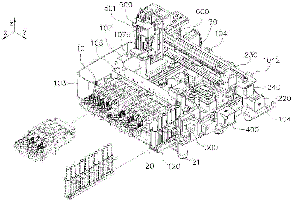
图1是根据本发明的实施例的自动体外诊断检查装置的立体图。FIG. 1 is a perspective view of an automatic in vitro diagnostic inspection device according to an embodiment of the present invention.
图2是根据本发明的实施例的自动体外诊断检查装置的主视图。Fig. 2 is a front view of the automatic in vitro diagnostic inspection device according to the embodiment of the present invention.
图3是根据本发明的实施例的自动体外诊断检查装置的去除壳体的状态的立体图。Fig. 3 is a perspective view of a state in which a case is removed of the automatic in vitro diagnostic inspection device according to the embodiment of the present invention.
图4是根据本发明的实施例的自动体外诊断检查装置的去除壳体的状态的俯视图。Fig. 4 is a top view of the automatic in vitro diagnostic inspection device according to the embodiment of the present invention in a state where the housing is removed.
图5是根据本发明的实施例的比色皿架的立体图。Fig. 5 is a perspective view of a cuvette holder according to an embodiment of the present invention.
图6是根据本发明的实施例的混合部的立体图。Fig. 6 is a perspective view of a mixing section according to an embodiment of the present invention.
图7的(a)、(b)和(c)分别是根据本发明的实施例的混合部的立体图、侧视图和主视图。(a), (b) and (c) of FIG. 7 are a perspective view, a side view, and a front view, respectively, of a mixing part according to an embodiment of the present invention.
图8和图9是分别示出根据本发明的实施例的采集操作部和光学分析部的立体图。8 and 9 are perspective views respectively showing an acquisition operation part and an optical analysis part according to an embodiment of the present invention.
图10是根据本发明的实施例的采集操作部的主视图。Fig. 10 is a front view of the acquisition operation part according to the embodiment of the present invention.
图11的(a)、(b)分别是根据本发明的实施例的省略采集操作部的部分结构(泵单元)的采集操作部的立体图和主视图。(a) and (b) of FIG. 11 are respectively a perspective view and a front view of a collection operation part omitting a partial structure (pump unit) of the collection operation part according to an embodiment of the present invention.
图12的(a)、(b)分别是根据本发明的实施例的省略采集操作部的部分结构(吸头适配器单元)的采集操作部的立体图和主视图。(a) and (b) of FIG. 12 are respectively a perspective view and a front view of a collection operation part omitting a partial structure (tip adapter unit) of the collection operation part according to an embodiment of the present invention.
图13示出根据本发明的实施例的自动体外诊断检查装置的结构。Fig. 13 shows the structure of an automatic in vitro diagnostic inspection device according to an embodiment of the present invention.
图14是根据本发明的另一实施例的自动体外诊断检查装置的主要部分立体结构图。Fig. 14 is a perspective view of main parts of an automatic in vitro diagnostic inspection device according to another embodiment of the present invention.
附图标记说明Explanation of reference signs
10:比色皿架 20:试管架10: Cuvette rack 20: Test tube rack
101:壳体 104:基架101: shell 104: base frame
110:比色皿托盘 120:试管托盘110: cuvette tray 120: test tube tray
210:第一驱动部 220:第二驱动部210: the first driving part 220: the second driving part
230:第三驱动部 240:第四驱动部230: The third drive unit 240: The fourth drive unit
300:码识别部 400:混合部300: code recognition part 400: mixing part
410:升降模块 420:第五驱动部410: Lifting module 420: Fifth drive unit
430:固定头 440:第六驱动部430: fixed head 440: sixth drive unit
500:采集操作部 600:光学分析部500: Acquisition Operation Department 600: Optical Analysis Department
具体实施方式Detailed ways
在本发明的实施例中提出的特定结构或功能描述仅为了描述根据本发明的概念的实施例而示出,并且根据本发明的概念的实施例可以以各种形式实施。此外,不应被解释为限于本说明书中描述的实施例,应当理解为包括本发明的思想和技术范围所包含的所有修改物、等同物以及替代物。Specific structural or functional descriptions presented in the embodiments of the present invention are shown only to describe embodiments according to the concept of the present invention, and embodiments according to the concept of the present invention may be implemented in various forms. Furthermore, it should not be construed as being limited to the embodiments described in this specification, but should be understood as including all modifications, equivalents, and substitutions included in the idea and technical scope of the present invention.
另一方面,在本发明中,第一和/或第二等术语可以用于描述各种组件,但所述组件不限于所述术语。所述术语仅用于将一个组件与另一组件区分开,例如,在不脱离根据本发明的概念的权利要求的范围内,可以将第一组件称为第二组件。类似地,第二组件也可以被称为第一组件。On the other hand, in the present invention, terms such as first and/or second may be used to describe various components, but the components are not limited to the terms. The terms are used only to distinguish one component from another, for example, a first component may be referred to as a second component within the scope of the claims without departing from the concept according to the present invention. Similarly, a second component may also be referred to as a first component.
当描述某个组件“连接”或“联接”到其他组件时,应理解为某个组件可以直接连接或联接到所述其他组件,但是中间还可以存在其他组件。另一方面,当描述某个组件“直接连接”或“直接接触”到其他组件时,应理解为中间不存在其他组件。应同样地理解用于描述组件之间关系的其他表述,例如“在~之间”和“直接在~之间”或“与~相邻”和“直接与~相邻”等表述。When it is described that a component is "connected" or "coupled" to other components, it will be understood that a component may be directly connected or coupled to the other components but intervening components may also be present. On the other hand, when it is described that an element is "directly connected" or "in direct contact with" another element, it should be understood that there is no intervening element. Other expressions used to describe the relationship between components, such as "between" and "directly between" or "adjacent to" and "directly adjacent to" etc., should be likewise understood.
在本说明书中使用的术语仅用于说明特定实施例,并非旨在限定本发明。除非在上下文中另有说明,否则单数包括复数。需要理解的是,在本说明书中,“包括”或“具有”等术语是用于指定实施的特征、数字、步骤、操作、组件、部件或其组合的存在,而不是预先排除一个或多个其他特征、数字、步骤、操作、组件、部件或其组合的存在或附加可能性。The terms used in this specification are for describing specific embodiments only, and are not intended to limit the present invention. The singular includes the plural unless the context dictates otherwise. It should be understood that in this specification, terms such as "comprising" or "having" are used to specify the presence of implemented features, numbers, steps, operations, components, parts or combinations thereof, rather than pre-excluding one or more The presence or additional possibility of other features, numbers, steps, operations, components, parts or combinations thereof.
以下,参照附图对本发明进行详细说明。Hereinafter, the present invention will be described in detail with reference to the drawings.
图1和图2分别是示出根据本发明的实施例的自动体外诊断检查装置的外观的立体图和主视图。1 and 2 are a perspective view and a front view, respectively, showing the appearance of an automatic in vitro diagnostic inspection device according to an embodiment of the present invention.
参照图1和图2,在本实施例的自动体外诊断检查装置中,在构成外观的壳体101的前部设置有输出设备的操作和分析结果的触摸屏102,并且设置有从触摸屏102的下端插入比色皿架10的第一插入口和与第一插入口平行地插入试管架20的第二插入口。本实施例示出比色皿架10被构成为两排,每个比色皿架10虽然具有相同的结构,但可以彼此独立地前后移动。在以下说明中,由于被构成为两排的比色皿架10彼此相同,因此仅使用一个附图标记进行说明而不作区分。尽管,本实施例示出比色皿架10被构成为两排,但是可以设置更多的排。另外,在本实施例中,在两排比色皿架10之间可以进一步包括缓冲试管架30(见图3),该缓冲试管架30容纳装有用于稀释颗粒的缓冲溶液的多个缓冲试管,并且该缓冲试管架30可以通过单独的驱动部前后移动。另一方面,除了缓冲试管之外,还可以容纳含有预处理溶液的预处理试管。Referring to Fig. 1 and Fig. 2, in the automatic in vitro diagnostic inspection device of the present embodiment, a
在壳体101的侧面可以设置有用于收集使用后的吸头的吸头收集容器103,并且在吸头收集容器103的上部设置有用于分离使用后的吸头的吸头去除部107(见图3),在吸头去除部107的上端形成有形成开口的吸头去除用孔107a,该吸头去除部107用于去除安置在采集操作部的吸头适配器上的吸头13,将在相关附图中再次对其进行说明。壳体101可以包括在上部将诊断结果打印输出的打印机101a。The side of
图3和图4分别是根据本发明的实施例的自动体外诊断检查装置的去除壳体的状态的立体图和俯视图。3 and 4 are a perspective view and a top view, respectively, of the automatic in vitro diagnostic inspection device according to an embodiment of the present invention in a state where the housing is removed.
参照图3和图4,本实施例的自动体外诊断检查装置包括:基架104;比色皿托盘110和试管托盘120,设置为在所述基架104上可在前后方向(x轴方向)上移动;采集操作部500和光学分析部600,设置为相对于基架104可在左右方向(y轴方向)上移动;以及多个驱动部210、220、230、240,用于驱动每个驱动元件,优选地,自动体外诊断检查装置进一步包括:码识别部300,固定在基架104上,识别附接在试管上的码信息;以及混合部400,固定在基架104上,混合容纳在试管中的样本。作为参考,为了便于空间的描述,本实施例中关于方向的术语应被理解为相对性术语,即,以比色皿托盘110和试管托盘120所在的水平面为基准,将其移动方向描述为前后方向(x轴),并且将与前后方向垂直的方向描述为左右方向(y轴)。Referring to Fig. 3 and Fig. 4, the automatic in vitro diagnostic inspection device of the present embodiment comprises:
基架104可以包括用于支撑主要结构或引导各种移动元件的移动方向的部件,并且可以包括多个面板的组合或用于引导移动元件的移动方向的引导部件,其不限于特定的构造或形式。The
具体地,比色皿托盘110和试管托盘120在基架104上可在前后方向(x轴)上移动,并且基架104可以设置有导轨,用于分别在前后方向上引导比色皿托盘110和试管托盘120。比色皿托盘110和试管托盘120通过设置在基架104上的第一驱动部210和第二驱动部220来实现前后移动。第一驱动部210和第二驱动部220可以被设置为通过履带式皮带分别向比色皿托盘110和试管托盘120提供驱动力的电动马达,并且根据每个电动马达的旋转方向,可以精确地控制比色皿托盘110和试管托盘120在前后方向(x轴)上的位置。另一方面,为了精确地控制比色皿托盘110和试管托盘120的位置,每个驱动部可以进一步包括编码器或用于控制位置的位置检测传感器。Specifically, the
采集操作部500和光学分析部600在基架104上可在左右方向(y轴方向)上移动。在基架104中,在比色皿托盘110和试管托盘120的前后移动区间的预定高度上设置有在左右方向上安装的第一上部框架1041和第二上部框架1042,从而采集操作部500和光学分析部600分别沿上部框架1041、1042在左右方向上移动。The
采集操作部500和光学分析部600分别通过分别设置在第一上部框架1041和第二上部框架1042中的第三驱动部230和第四驱动部240在左右方向上移动。所述第三驱动部230和第四驱动部240可以被设置为通过履带式皮带分别向采集操作部500光学分析部600提供驱动力的电动马达,并且根据每个电动马达的旋转方向,可以精确地控制采集操作部500和光学分析部600在左右方向(y轴)上的位置。另一方面,为了精确地控制采集操作部500和光学分析部600的位置,每个驱动部可以进一步包括编码器或用于控制位置的位置检测传感器。另一方面,虽然本实施例中示出每个驱动部210、220、230、240通过皮带传递电动马达的驱动力,但不限于此,可以使用诸如线性驱动部的各种已知的驱动力传递装置。The
优选地,采集操作部500可以进一步包括用于拍摄图像的摄像头模块501,摄像头模块501可以在与采集操作部500一起水平移动的同时检测图像信息,从而可以用于识别盒信息、吸头以及缓冲试管是否存在等。Preferably, the
附图标记105是设置有条形码阅读器的PCB(印刷电路板),所述条形码阅读器设置在比色皿托盘110的前后移动区间的上部以识别设置在比色皿架10的每个比色皿的条形码。
码识别部300邻近试管托盘120而设置,并且识别附接在试管架20和/或容纳在试管架20中的每个试管21的码信息。这种码信息包括关于样本的信息,并且可以设置为条形码或QR码。另一方面,可以进一步包括邻近码识别部300的单独的摄像头,并且这种摄像头可以用于确定容纳在试管架20中的试管的类型(尺寸)。The
以下,参照相关附图详细描述每个详细结构。Hereinafter, each detailed structure is described in detail with reference to related drawings.
比色皿托盘110为安置比色皿架10的部件,优选地,比色皿托盘110可以进一步包括用于将安置的比色皿架10保持在预定条件的温度的温度调节部,例如,这种温度调节部可以被设置为能够调节温度的已知的帕尔帖元件和风扇,但不限于此,在能够调节比色皿架的温度并保持恒度的范围内,可以使用已知的温度调节装置。另一方面,比色皿架10和比色皿托盘110可以彼此集成为一体,或者,比色皿架10和比色皿托盘110也可以分离。在这种比色皿架10中,进行样本和试剂的混合和反应的多个比色皿并排布置,并且每个比色皿包括检查所需的试剂、吸头和分析条(assay strip)。The
图5示出根据本发明的实施例的比色皿架。Figure 5 shows a cuvette holder according to an embodiment of the present invention.
参照图5,比色皿架10被构成为将多个比色皿彼此并排布置,其中每个比色皿包括至少一个开放室11、试剂室12、至少一个吸头13以及包括分析条的盒14并构成一个单位组。在开放室11中,样本被分配并与试剂混合,并且试剂室12填充有待与样本进行反应的抗体等试剂。试剂室12一般通过密封纸(aluminum foil)密封,并且需要去除密封纸以进行检查。在本发明中,试剂室12的密封纸可以在检查装置中被去除,其详细描述将在相关附图中再次描述。Referring to FIG. 5, a
盒14包括通过滴落样本和试剂的混合物进行反应的分析条。然而,在比色皿架10中,各腔室和吸头的数量可以根据检查的类型而改变,例如,每排比色皿架10可以容纳不同的检查用比色皿,以对一个样本同时执行各种检查,或者,每排比色皿架10可以容纳相同的检查用比色皿,以同时对多个样本执行相同的检查。每个比色皿(盒)可以包括包含有关样本或试剂的信息的条形码(QR码)。
虽然在本实施例中示出比色皿架10分开设置每个腔室和包括分析条的盒14,也可以使用一体式的比色皿。例如,这种一体式比色皿可以由在本申请人的授权专利公报第10-1661098号(公开日期:2016年9月29日)中公开的多孔比色皿提供。Although in the present embodiment the
图14是根据本发明的另一实施例的自动体外诊断检查装置的主要部分立体结构图,图14示出采用多孔比色皿的自动体外诊断检查装置,对与前述实施例中的相同结构使用相同的附图标记。Fig. 14 is a three-dimensional structural view of main parts of an automatic in vitro diagnostic inspection device according to another embodiment of the present invention. Fig. 14 shows an automatic in vitro diagnostic inspection device using a porous cuvette, using the same structure as in the previous embodiment The same reference numerals.
参照图14,比色皿托盘110包括温度调节部111,并且在温度调节部111的上端组装有比色皿架10’。本实施例中示出在比色皿架10’中形成有分别容纳多孔比色皿40的五排的槽31,并且槽31的数量可以增加或减少。多孔比色皿40具有多孔(multi-well)结构,所述多孔结构具有多个孔(well)和通过区分孔来防止试剂和试样之间混合的屏障,并且所述多孔比色皿40包括至少一个吸头13、具有容纳试样和试剂的多个腔室41a的反应腔室部41和检测试样和试剂之间的反应的检测部42。检测部42包括适用于对在所述反应腔室部100中进行的所述试样和试剂之间的反应生产物进行色谱分析的色谱分析装置。此外,检测部42包括试样投入口42a和测量窗42b。该检测部42可以包括适用于反应物的色谱分析,例如侧流分析的装置。优选地,检测部42可以包括用于侧流分析(lateral flow assay)的盒。附图标记42a和42b分别为盒的试样投入口和盒的测量窗。Referring to FIG. 14 , the
图6是根据本发明的实施例的混合部的立体图,图7的(a)、(b)、(c)分别是根据本发明的实施例的混合部的立体图、侧视图和主视图。6 is a perspective view of a mixing part according to an embodiment of the present invention, and (a), (b) and (c) of FIG. 7 are a perspective view, a side view and a front view of the mixing part according to an embodiment of the present invention, respectively.
参照图6和图7,试管架20容纳并排布置的多个试管21,并且试管21安置在试管托盘120上,以通过一系列的过程对每个试管21的样本进行检查,优选地,试管21为无盖试管(capless tube)。Referring to FIGS. 6 and 7 , the
混合部400用于混合每个试管21的样本(例如,血液),混合部400包括:固定支架106,固定在基架上;升降模块410,被固定支架106支撑以上下移动;第五驱动部420,用于上下驱动升降模块410;固定头430,可转动地被升降模块410支撑,并且能够与试管21的上侧开口端紧贴固定;以及第六驱动部440,设置在升降模块410并驱动固定头430旋转。Mixing
固定支架106在垂直方向上设置有导轨1061,升降模块410组装在导轨1061,以通过第五驱动部420上下移动。The fixed
升降模块410设置有线性驱动部411,该线性驱动部411通过第五驱动部420和皮带412传递驱动力,以通过第五驱动部420的正向或反向旋转上下驱动升降模块410。The
固定头430在旋转轴方向C上可自由旋转地被升降模块410支撑,并且与试管21的上侧开口端紧贴固定。优选地,固定头430可以进一步包括具有弹性的接触垫,以增加与试管21直接紧贴的下侧接触端的紧贴力,接触垫的材料可以是具有弹性的橡胶材料。The fixing
通过固定在升降模块410的第六驱动部440驱动固定头430旋转,在本实施例中,第六驱动部440包括通过皮带使固定头430的驱动轴旋转的电动马达。附图标记441为用于调节皮带张力的张力调节皮带轮。The fixing
在通过如上所述构成的混合部400对试管21进行的样本混合过程中,在试管21水平移动以与固定头430的旋转轴方向C平行排列的初始位置,试管21的上端与固定头430之间为隔开预定距离G的状态,之后,在升降模块410通过第五驱动部420向下移动的同时,固定头430与试管21的上侧开口端紧贴。接下来,固定头430和试管21通过第六驱动部440的旋转驱动力一起旋转(自转),从而实现样本的混合。During the sample mixing process of the
附图标记22为设置在试管架中并支撑试管21的下端以辅助试管21的自转运动的部件。
图8和图9分别是示出根据本发明的实施例的采集操作部和光学分析部的立体图,为了帮助理解,省略除了采集操作部和光学分析部之外的其他结构。箭头F表示比色皿架的插入方向。FIG. 8 and FIG. 9 are perspective views showing the collection operation part and the optical analysis part according to the embodiment of the present invention respectively, and to facilitate understanding, other structures except the collection operation part and the optical analysis part are omitted. Arrow F indicates the insertion direction of the cuvette holder.
参照图8和图9,采集操作部500被设置成可沿第一上部框架1041移动,第一上部框架1041在左右方向上安装于基架104上部的预定高度上,第一上部框架1041在长度方向上设置有第一导梁1043。采集操作部500组装在第一导梁1043上,并可沿第一上部框架1041在左右方向(y轴)上移动。在第一上部框架1041的一侧固定有第三驱动部230。第三驱动部230的驱动轴连接到皮带,采集操作部500固定到皮带,从而通过第三驱动部230的正向旋转或反向旋转驱动来控制采集操作部500在左右方向(y轴)上的位置。Referring to Fig. 8 and Fig. 9, the
光学分析部600被设置成可沿第二上部框架1042移动,第二上部框架1042在左右方向上安装于基架104上部的预定高度,并且第二上部框架1042在长度方向上设置有第二导梁1044。光学分析部600组装在第二导梁1044上,并可沿第二上部框架1042在左右方向(y轴)上移动。在第二上部框架1042的一侧固定有第四驱动部240,第四驱动部240的驱动轴连接到皮带,光学分析部600固定到该皮带,从而能够通过第四驱动部240的正向旋转或反向旋转驱动来控制光学分析部600在左右方向(y轴)上的位置。The
光学分析部600通过读取由每个比色皿的分析条检测到的反应结果来生成数据,并可以由此获得样本中包含的特定对象分析物的定性和/或定量结果。The
图10是根据本发明的实施例的采集操作部500的主视图。图11的(a)、(b)分别是根据本发明的实施例的省略采集操作部的部分结构(泵单元)的采集操作部的立体图和主视图,图12的(a)、(b)分别是根据本发明的实施例的省略采集操作部的部分结构(吸头适配器单元)的采集操作部的立体图和主视图。FIG. 10 is a front view of the
参照图10、图11的(a)、(b)以及图12的(a)、(b),采集操作部500包括:主板510,组装在第一导梁1043上,可沿第一导梁1043水平移动;吸头适配器520,可上下移动地设置在主板510上,并且能够与设置在比色皿架中的吸头13过盈装配;第七驱动部530,用于上下驱动吸头适配器520;泵单元540,平行于吸头适配器520可上下移动地设置在主板510,并向吸头适配器520提供吸力或排力;以及第八驱动部550,用于上下驱动泵单元540。Referring to Fig. 10, (a) and (b) of Fig. 11 and (a) and (b) of Fig. 12, the
吸头适配器单元包括固定到吸头适配器块521的吸头适配器520。吸头适配器520为中空形状的部件,其上端通过挠性管(flexible tube)522连接到泵单元540,在下侧前端上具有小的外径,并且能够与吸头13过盈装配。在本实施例中,吸头13大致为圆锥形状,并且是上端突出形成有突出部13a的一次性吸头(tip),其能够通过与吸头适配器520的下端的摩擦力进行过盈装配。另一方面,在使用后的吸头13的分离过程中,吸头适配器520和整个吸头13移动到吸头去除部107(参照图3)上部,并且在吸头13的突出部13a位于吸头去除用孔107a的端部下方的状态下,在吸头适配器520上升时,吸头13可以从吸头适配器520上分离,并且分离的吸头13通过吸头去除部107被回收到吸头收集容器103中。The tip adapter unit includes a
吸头适配器块521通过第七驱动部530上下驱动,该第七驱动部530可以包括:电动马达531;惰轮532,可转动地设置在主板510上;以及皮带533,连接电动马达531的驱动轴5311和惰轮532。吸头适配器块521固定到皮带533上以根据皮带533的旋转方向调节上下高度。主板510可以设置有引导吸头适配器块521的上下移动的第三导梁5111。The suction
优选地,主板510设置在与吸头13的安装高度相对应的位置,并且进一步包括能够检测吸头13是否存在的吸头检测部512。Preferably, the
泵单元540通过挠性管522连接到吸头适配器520以提供吸力或排力,并且包括可上下移动地设置在主板510上的引导块541,从而可以通过第八驱动部调节上下高度。与第七驱动部530相同地,第八驱动部550可以被设置为通过皮带调节引导块541的高度的电动马达。The
主板510可以设置有用于引导引导块541的上下移动的第四导梁5112。The
优选地,引导块541包括在垂直方向上固定的穿孔结构,该穿孔结构可以被设置为尖状的穿孔吸头560。穿孔吸头560在通过第八驱动部550的驱动下降的同时,起到对密封每个比色皿的试剂室的密封纸进行穿孔的作用。Preferably, the
图13示出根据本发明的一个实施例的自动体外诊断检查装置的结构。Fig. 13 shows the structure of an automatic in vitro diagnostic inspection device according to an embodiment of the present invention.
参照图13,本实施例的自动体外诊断检查装置根据算法控制用于检查的一系列操作,并且包括计算由光学分析部600产生的检测信号并导出测量结果的控制/运算部700,并将其结果输出到触摸屏102或打印机101a。另一方面,本实施例的自动体外诊断检查装置设置有通信部710和存储部720,从而可以通过通信部710将检查结果发送到医院系统等远程站或从远程站接收检查结果,或将检查结果存储在单独的存储部720中。此外,控制/运算部700可以集成控制用于驱动每个驱动元件的驱动部210、220、230、240、码识别部300、混合部400和采集操作部500。Referring to FIG. 13 , the automatic in vitro diagnostic inspection device of this embodiment controls a series of operations for inspection according to an algorithm, and includes a control/
对如上所述构成的自动体外诊断检查装置的示意性检查过程进行说明。A schematic inspection procedure of the automatic in vitro diagnostic inspection device configured as described above will be described.
参照图3至图5、图13,在比色皿架10中插入待测项目(item)的盒14,此时,可以通过传感器确认是否插入有盒14。通过操作按钮的操作,比色皿托盘110向后移动并在插入有盒14的槽中识别条形码,从而判断存储的项目是否与批次(lot)信息匹配。Referring to Fig. 3 to Fig. 5 and Fig. 13, the
接下来,当装有试样的试管21通过试管架20插入到装置内部时,可以通过识别试管架20的条形码来判断安装在试管架20上的试管21的信息并进行与安装在试管架20上的试样数量一样多的检查。此后,根据程序步骤进行检查,并存储从试样条形码中取出的试样的信息,此时,当从医院系统接收试样信息时,可以增加判断是否与对应试样匹配的过程。当装在试管21中的试样为全血时,可以在混合部400中进行混合操作,采集操作部500安装吸头13并采集试样以自动进行预处理(混合)操作和分配到盒14中的操作。在使用后,吸头13排出到吸头收集容器103中。Next, when the
分配操作完成的盒14根据项目信息等待反应等待时间,然后移动到光学分析部600并进行光学扫描,扫描完成的模拟信号转换为数字信号并传送到控制/运算部700,然后控制/运算部700使用适用于项目的运算公式进行分析,然后将检查结果输出到外部。The
以上说明的本发明不限于上述实施例和附图,对本发明所属领域的普通技术人员显而易见的是,可以在不脱离本发明的技术思想的范围内进行各种置换、变形和改变。The present invention described above is not limited to the above-mentioned embodiments and drawings, and it is obvious to those skilled in the art that various replacements, deformations and changes can be made within the scope of the technical idea of the present invention.
Claims (9)
Applications Claiming Priority (2)
| Application Number | Priority Date | Filing Date | Title |
|---|---|---|---|
| KR1020210065755A KR102568429B1 (en) | 2021-05-21 | 2021-05-21 | Automatic In-vitro diagnostic apparatus |
| KR10-2021-0065755 | 2021-05-21 |
Publications (1)
| Publication Number | Publication Date |
|---|---|
| CN115372345A true CN115372345A (en) | 2022-11-22 |
Family
ID=81392650
Family Applications (1)
| Application Number | Title | Priority Date | Filing Date |
|---|---|---|---|
| CN202210554937.8A Pending CN115372345A (en) | 2021-05-21 | 2022-05-20 | Automatic in vitro diagnosis and examination device |
Country Status (4)
| Country | Link |
|---|---|
| US (1) | US20220373571A1 (en) |
| EP (1) | EP4092421B1 (en) |
| KR (1) | KR102568429B1 (en) |
| CN (1) | CN115372345A (en) |
Families Citing this family (7)
| Publication number | Priority date | Publication date | Assignee | Title |
|---|---|---|---|---|
| USD921222S1 (en) * | 2019-01-04 | 2021-06-01 | Meso Scale Technologies, Llc. | Instrument |
| USD924431S1 (en) | 2019-04-18 | 2021-07-06 | Beckman Coulter, Inc. | Analysis machine |
| USD992750S1 (en) | 2020-11-13 | 2023-07-18 | BIOMéRIEUX, INC. | Sample handling system |
| WO2024117638A1 (en) * | 2022-11-29 | 2024-06-06 | 주식회사 인텍메디 | In vitro diagnosis device |
| KR20240132813A (en) * | 2023-02-27 | 2024-09-04 | 주식회사 인텍메디 | In-vitro diagnostic apparatus |
| CN116577172B (en) * | 2023-07-14 | 2023-10-27 | 广州兰泰胜科技有限公司 | Urine sample pretreatment device based on coprecipitation-separation oxidation method |
| CN118687929B (en) * | 2024-08-22 | 2024-10-29 | 山东睿恒环保建材有限公司 | A fixed-point detection sampling device for aqueous aluminum powder paste |
Citations (7)
| Publication number | Priority date | Publication date | Assignee | Title |
|---|---|---|---|---|
| DK175090D0 (en) * | 1989-07-24 | 1990-07-23 | Technicon Instr | PROCEDURE FOR ANALYZING A NUMBER OF LIQUID SAMPLES AND APPARATUS FOR EXERCISING THE PROCEDURE |
| EP0806672A2 (en) * | 1996-05-06 | 1997-11-12 | Helena Laboratories Corporation | Method and apparatus for handling a sample |
| WO2015072757A1 (en) * | 2013-11-15 | 2015-05-21 | 바디텍메드 주식회사 | Station used for test device provided with integrated reaction and detection means |
| WO2016182382A1 (en) * | 2015-05-14 | 2016-11-17 | 바디텍메드(주) | Station, used for test apparatus, having integrated reaction and detection means |
| WO2017149234A1 (en) * | 2016-03-01 | 2017-09-08 | Arteion | Automatic analysing system for in vitro diagnostics |
| US20180074027A1 (en) * | 2015-05-14 | 2018-03-15 | Boditech Med Inc. | System and method for analyzing biological fluid in multiple cuvettes |
| EP3534140A1 (en) * | 2016-10-28 | 2019-09-04 | Boditech Med Inc. | Device and method for mixing sample by using capless tube |
Family Cites Families (6)
| Publication number | Priority date | Publication date | Assignee | Title |
|---|---|---|---|---|
| AU777102B2 (en) * | 2000-01-13 | 2004-09-30 | Ortho-Clinical Diagnostics, Inc. | Failure detection in automated clinical analyzers |
| WO2012036296A1 (en) * | 2010-09-17 | 2012-03-22 | ユニバーサル・バイオ・リサーチ株式会社 | Cartridge and automatic analysis device |
| US10393738B2 (en) | 2013-11-12 | 2019-08-27 | Boditech Med Inc. | Multi-well cuvette provided with integrated reaction and detection means |
| KR101811786B1 (en) * | 2015-05-14 | 2017-12-22 | 바디텍메드(주) | Station for test device with integrated reaction and detection means |
| US11204358B2 (en) * | 2016-05-25 | 2021-12-21 | Universal Bio Research Co., Ltd. | Specimen processing and measuring system |
| EP3814254B1 (en) * | 2018-06-28 | 2023-08-02 | Bio-Rad Laboratories, Inc. | Container rotation device |
-
2021
- 2021-05-21 KR KR1020210065755A patent/KR102568429B1/en active Active
-
2022
- 2022-04-28 EP EP22170439.8A patent/EP4092421B1/en active Active
- 2022-05-02 US US17/734,184 patent/US20220373571A1/en active Pending
- 2022-05-20 CN CN202210554937.8A patent/CN115372345A/en active Pending
Patent Citations (8)
| Publication number | Priority date | Publication date | Assignee | Title |
|---|---|---|---|---|
| DK175090D0 (en) * | 1989-07-24 | 1990-07-23 | Technicon Instr | PROCEDURE FOR ANALYZING A NUMBER OF LIQUID SAMPLES AND APPARATUS FOR EXERCISING THE PROCEDURE |
| EP0806672A2 (en) * | 1996-05-06 | 1997-11-12 | Helena Laboratories Corporation | Method and apparatus for handling a sample |
| US5879628A (en) * | 1996-05-06 | 1999-03-09 | Helena Laboratories Corporation | Blood coagulation system having a bar code reader and a detecting means for detecting the presence of reagents in the cuvette |
| WO2015072757A1 (en) * | 2013-11-15 | 2015-05-21 | 바디텍메드 주식회사 | Station used for test device provided with integrated reaction and detection means |
| WO2016182382A1 (en) * | 2015-05-14 | 2016-11-17 | 바디텍메드(주) | Station, used for test apparatus, having integrated reaction and detection means |
| US20180074027A1 (en) * | 2015-05-14 | 2018-03-15 | Boditech Med Inc. | System and method for analyzing biological fluid in multiple cuvettes |
| WO2017149234A1 (en) * | 2016-03-01 | 2017-09-08 | Arteion | Automatic analysing system for in vitro diagnostics |
| EP3534140A1 (en) * | 2016-10-28 | 2019-09-04 | Boditech Med Inc. | Device and method for mixing sample by using capless tube |
Also Published As
| Publication number | Publication date |
|---|---|
| EP4092421A1 (en) | 2022-11-23 |
| KR102568429B1 (en) | 2023-08-23 |
| US20220373571A1 (en) | 2022-11-24 |
| EP4092421C0 (en) | 2025-02-12 |
| EP4092421B1 (en) | 2025-02-12 |
| KR20220157788A (en) | 2022-11-29 |
Similar Documents
| Publication | Publication Date | Title |
|---|---|---|
| CN115372345A (en) | Automatic in vitro diagnosis and examination device | |
| KR101811786B1 (en) | Station for test device with integrated reaction and detection means | |
| KR101646549B1 (en) | System for test device with integrated reaction and detection means | |
| US8741655B2 (en) | Transport system for test sample carrier | |
| KR101868824B1 (en) | Immune reaction diagonostic automating system | |
| US7578978B2 (en) | Carrier for holding test samples | |
| US8512636B2 (en) | Compact, integrated system for processing test samples | |
| US8623293B2 (en) | Sealer for test sample devices | |
| CN111487402A (en) | Semi-automatic immunofluorescence analyzer | |
| WO2015072757A1 (en) | Station used for test device provided with integrated reaction and detection means | |
| CN212540420U (en) | Semi-automatic immunofluorescence analyzer | |
| CN114966068A (en) | Modular full-automatic POCT analyzer | |
| JP2003075452A (en) | Biochemical analyzer and specimen adaptor |
Legal Events
| Date | Code | Title | Description |
|---|---|---|---|
| PB01 | Publication | ||
| PB01 | Publication | ||
| SE01 | Entry into force of request for substantive examination | ||
| SE01 | Entry into force of request for substantive examination |