CN115369619A - Laundry appliance with laundry accessories - Google Patents
Laundry appliance with laundry accessories Download PDFInfo
- Publication number
- CN115369619A CN115369619A CN202210470948.8A CN202210470948A CN115369619A CN 115369619 A CN115369619 A CN 115369619A CN 202210470948 A CN202210470948 A CN 202210470948A CN 115369619 A CN115369619 A CN 115369619A
- Authority
- CN
- China
- Prior art keywords
- auxiliary
- cabinet
- wand assembly
- air
- cover
- Prior art date
- Legal status (The legal status is an assumption and is not a legal conclusion. Google has not performed a legal analysis and makes no representation as to the accuracy of the status listed.)
- Pending
Links
Images


Classifications
-
- D—TEXTILES; PAPER
- D06—TREATMENT OF TEXTILES OR THE LIKE; LAUNDERING; FLEXIBLE MATERIALS NOT OTHERWISE PROVIDED FOR
- D06F—LAUNDERING, DRYING, IRONING, PRESSING OR FOLDING TEXTILE ARTICLES
- D06F39/00—Details of washing machines not specific to a single type of machines covered by groups D06F9/00 - D06F27/00
-
- D—TEXTILES; PAPER
- D06—TREATMENT OF TEXTILES OR THE LIKE; LAUNDERING; FLEXIBLE MATERIALS NOT OTHERWISE PROVIDED FOR
- D06F—LAUNDERING, DRYING, IRONING, PRESSING OR FOLDING TEXTILE ARTICLES
- D06F58/00—Domestic laundry dryers
- D06F58/20—General details of domestic laundry dryers
-
- D—TEXTILES; PAPER
- D06—TREATMENT OF TEXTILES OR THE LIKE; LAUNDERING; FLEXIBLE MATERIALS NOT OTHERWISE PROVIDED FOR
- D06F—LAUNDERING, DRYING, IRONING, PRESSING OR FOLDING TEXTILE ARTICLES
- D06F58/00—Domestic laundry dryers
- D06F58/20—General details of domestic laundry dryers
- D06F58/203—Laundry conditioning arrangements
-
- D—TEXTILES; PAPER
- D06—TREATMENT OF TEXTILES OR THE LIKE; LAUNDERING; FLEXIBLE MATERIALS NOT OTHERWISE PROVIDED FOR
- D06F—LAUNDERING, DRYING, IRONING, PRESSING OR FOLDING TEXTILE ARTICLES
- D06F25/00—Washing machines with receptacles, e.g. perforated, having a rotary movement, e.g. oscillatory movement, the receptacle serving both for washing and for centrifugally separating water from the laundry and having further drying means, e.g. using hot air
-
- D—TEXTILES; PAPER
- D06—TREATMENT OF TEXTILES OR THE LIKE; LAUNDERING; FLEXIBLE MATERIALS NOT OTHERWISE PROVIDED FOR
- D06F—LAUNDERING, DRYING, IRONING, PRESSING OR FOLDING TEXTILE ARTICLES
- D06F37/00—Details specific to washing machines covered by groups D06F21/00 - D06F25/00
-
- D—TEXTILES; PAPER
- D06—TREATMENT OF TEXTILES OR THE LIKE; LAUNDERING; FLEXIBLE MATERIALS NOT OTHERWISE PROVIDED FOR
- D06F—LAUNDERING, DRYING, IRONING, PRESSING OR FOLDING TEXTILE ARTICLES
- D06F37/00—Details specific to washing machines covered by groups D06F21/00 - D06F25/00
- D06F37/02—Rotary receptacles, e.g. drums
- D06F37/04—Rotary receptacles, e.g. drums adapted for rotation or oscillation about a horizontal or inclined axis
- D06F37/06—Ribs, lifters, or rubbing means forming part of the receptacle
-
- D—TEXTILES; PAPER
- D06—TREATMENT OF TEXTILES OR THE LIKE; LAUNDERING; FLEXIBLE MATERIALS NOT OTHERWISE PROVIDED FOR
- D06F—LAUNDERING, DRYING, IRONING, PRESSING OR FOLDING TEXTILE ARTICLES
- D06F57/00—Supporting means, other than simple clothes-lines, for linen or garments to be dried or aired
-
- D—TEXTILES; PAPER
- D06—TREATMENT OF TEXTILES OR THE LIKE; LAUNDERING; FLEXIBLE MATERIALS NOT OTHERWISE PROVIDED FOR
- D06F—LAUNDERING, DRYING, IRONING, PRESSING OR FOLDING TEXTILE ARTICLES
- D06F58/00—Domestic laundry dryers
- D06F58/02—Domestic laundry dryers having dryer drums rotating about a horizontal axis
-
- D—TEXTILES; PAPER
- D06—TREATMENT OF TEXTILES OR THE LIKE; LAUNDERING; FLEXIBLE MATERIALS NOT OTHERWISE PROVIDED FOR
- D06F—LAUNDERING, DRYING, IRONING, PRESSING OR FOLDING TEXTILE ARTICLES
- D06F58/00—Domestic laundry dryers
- D06F58/10—Drying cabinets or drying chambers having heating or ventilating means
-
- D—TEXTILES; PAPER
- D06—TREATMENT OF TEXTILES OR THE LIKE; LAUNDERING; FLEXIBLE MATERIALS NOT OTHERWISE PROVIDED FOR
- D06F—LAUNDERING, DRYING, IRONING, PRESSING OR FOLDING TEXTILE ARTICLES
- D06F39/00—Details of washing machines not specific to a single type of machines covered by groups D06F9/00 - D06F27/00
- D06F39/12—Casings; Tubs
-
- D—TEXTILES; PAPER
- D06—TREATMENT OF TEXTILES OR THE LIKE; LAUNDERING; FLEXIBLE MATERIALS NOT OTHERWISE PROVIDED FOR
- D06F—LAUNDERING, DRYING, IRONING, PRESSING OR FOLDING TEXTILE ARTICLES
- D06F57/00—Supporting means, other than simple clothes-lines, for linen or garments to be dried or aired
- D06F57/12—Supporting means, other than simple clothes-lines, for linen or garments to be dried or aired specially adapted for attachment to walls, ceilings, stoves, or other structures or objects
Landscapes
- Engineering & Computer Science (AREA)
- Textile Engineering (AREA)
- Accessory Of Washing/Drying Machine, Commercial Washing/Drying Machine, Other Washing/Drying Machine (AREA)
Abstract
本发明涉及一种具有洗衣附件的洗衣设备,包括柜体。用于输送辅助空气穿过辅助气流路径的鼓风机设置在柜体内。辅助棒状组件与辅助气流路径流体连通。辅助棒状组件被构造为用于将物品悬挂在其上并且提供辅助空气来对物品进行调节。

The invention relates to a laundry device with a laundry accessory, including a cabinet. A blower for delivering auxiliary air through the auxiliary airflow path is disposed within the cabinet. The auxiliary wand assembly is in fluid communication with the auxiliary gas flow path. The auxiliary wand assembly is configured to suspend items thereon and to provide auxiliary air to condition the items.
Description
技术领域technical field
本发明总体上涉及一种洗衣设备,并且更具体地涉及一种具有多个洗衣附件的洗衣设备。The present invention relates generally to a laundry appliance, and more particularly to a laundry appliance having a plurality of laundry accessories.
发明内容Contents of the invention
根据本发明的一个方面,一种洗衣设备包括柜体。鼓风机设置在柜体内,其用于穿过辅助气流路径输送辅助空气。辅助棒状组件与辅助气流路径流体连通。辅助棒状组件被构造为用于将物品悬挂在其上并且提供辅助空气来对物品进行调节。According to one aspect of the present invention, a laundry device includes a cabinet. A blower is disposed within the cabinet for delivering auxiliary air through the auxiliary airflow path. The auxiliary wand assembly is in fluid communication with the auxiliary gas flow path. The auxiliary wand assembly is configured to suspend items thereon and to provide auxiliary air to condition the items.
根据本发明的另一个方面,一种垂直轴洗衣机包括具有顶部面板的柜体,该顶部面板限定了出入口。盖与顶部面板耦合并且具有下表面。盖能够在位于出入口上方的升高位置与覆盖出入口的降低位置之间进行操作。可移除面板选择性地位于顶部面板上并且跨过出入口,以限定处理状态。加热元件位于盖与顶部面板中的至少一个的附近。加热元件被构造为对盖的下表面和可移除面板的上表面中的至少一个进行加热。当可移除面板处于处理状态并且盖处于降低位置时,盖的下表面和可移除面板的上表面被按压在一起来限定用于对衣物进行处理的褶皱处理空间。According to another aspect of the invention, a vertical axis washing machine includes a cabinet having a top panel defining an access opening. A cover is coupled to the top panel and has a lower surface. The cover is operable between a raised position over the access opening and a lowered position covering the access opening. A removable panel is optionally located on the top panel and across the doorway to define the treatment status. A heating element is located adjacent to at least one of the lid and the top panel. The heating element is configured to heat at least one of the lower surface of the cover and the upper surface of the removable panel. When the removable panel is in the processing state and the cover is in the lowered position, the lower surface of the cover and the upper surface of the removable panel are pressed together to define a crease processing space for processing the laundry.
根据本发明的另一个方面,一种垂直轴洗衣机包括柜体,其具有位于柜体的下部附近的基部。抽屉设置在基部内并且能够在位于基部内的存放位置与位于基部前方的支撑位置之间进行操作。台阶设置在抽屉内。台阶通过剪式连杆附接至抽屉。台阶被构造为当抽屉处于支撑位置时能够在平坦位置与台阶状位置之间进行操作。According to another aspect of the invention, a vertical axis washing machine includes a cabinet having a base located near a lower portion of the cabinet. A drawer is disposed within the base and is operable between a storage position within the base and a support position forward of the base. The steps are set in the drawer. The steps are attached to the drawers by scissor links. The step is configured to be operable between a flat position and a stepped position when the drawer is in the support position.
本领域技术人员参照以下说明、权利要求和附图将进一步理解和领会本发明的这些和其他的特征、优点和目的。These and other features, advantages and objects of the present invention will be further understood and appreciated by those skilled in the art with reference to the following description, claims and drawings.
附图说明Description of drawings
在附图中:In the attached picture:
图1A是根据本文描述的多个方面的具有表示为缩回位置的辅助棒状组件的洗衣设备的局部立体图;1A is a partial perspective view of a laundry appliance with an auxiliary wand assembly shown in a retracted position according to aspects described herein;
图1B是根据本文描述的多个方面的具有表示为缩回位置的辅助棒状组件的洗衣设备的切开的立体图;1B is a cut-away perspective view of a laundry appliance with an auxiliary wand assembly shown in a retracted position, according to aspects described herein;
图1C是根据本文描述的多个方面的具有表示为伸出位置的辅助棒状组件的洗衣设备的局部立体图;1C is a partial perspective view of a laundry appliance with an auxiliary wand assembly shown in an extended position, according to aspects described herein;
图1D是根据本文描述的多个方面的具有表示为伸出位置的辅助棒状组件的洗衣设备的局部立体图;1D is a partial perspective view of a laundry appliance with an auxiliary wand assembly shown in an extended position, according to aspects described herein;
图2是洗衣设备的示意性剖视图,并且示出了辅助端口的一个方面;Figure 2 is a schematic cross-sectional view of a laundry appliance and showing an aspect of an auxiliary port;
图3是洗衣设备的示意性剖视图,并且示出了辅助端口的一个方面;Figure 3 is a schematic cross-sectional view of a laundry appliance and showing an aspect of an auxiliary port;
图4A是辅助端口的一个方面的示意性剖视图,示出了常规状态下的挡板;Figure 4A is a schematic cross-sectional view of one aspect of an auxiliary port, showing the baffle in a normal state;
图4B是图4A的辅助端口的示意性剖视图,其中挡板移入到辅助状态;FIG. 4B is a schematic cross-sectional view of the auxiliary port of FIG. 4A with the shutter moved into the auxiliary state;
图5A是根据本文描述的多个方面的具有表示为伸出位置的辅助棒状组件的洗衣设备的立体图;5A is a perspective view of a laundry appliance with an auxiliary wand assembly shown in an extended position, according to aspects described herein;
图5B是根据本文描述的多个方面的具有图5A的辅助棒状组件的洗衣设备的局部立体图;5B is a partial perspective view of a laundry appliance with the auxiliary wand assembly of FIG. 5A in accordance with aspects described herein;
图6A是根据本文描述的多个方面的具有表示为伸出位置的辅助棒状组件的洗衣设备的局部立体图;6A is a partial perspective view of a laundry appliance with an auxiliary wand assembly shown in an extended position, according to aspects described herein;
图6B是根据本文描述的多个方面的具有图6A的辅助棒状组件的洗衣设备的局部侧视图;6B is a partial side view of the laundry appliance with the auxiliary wand assembly of FIG. 6A according to aspects described herein;
图7A是根据本文描述的多个方面的具有表示为缩回位置的辅助棒状组件的洗衣设备的局部前视立体图;7A is a partial front perspective view of a laundry appliance with an auxiliary wand assembly shown in a retracted position, according to aspects described herein;
图7B是根据本文描述的多个方面的具有表示为伸出位置的辅助棒状组件的洗衣设备的立体图;7B is a perspective view of a laundry appliance with an auxiliary wand assembly shown in an extended position, according to aspects described herein;
图7C是根据本文描述的多个方面的具有图7A的辅助棒状组件的洗衣设备的立体图;7C is a perspective view of a laundry appliance with the auxiliary wand assembly of FIG. 7A according to aspects described herein;
图8A是根据本文描述的多个方面的具有表示为附接至辅助端口的辅助棒状组件的洗衣设备的侧视立体图;8A is a side perspective view of a laundry appliance having an auxiliary wand assembly shown attached to an auxiliary port, according to aspects described herein;
图8B是根据本文描述的多个方面的图8A的洗衣设备的局部立体图;8B is a partial perspective view of the laundry appliance of FIG. 8A according to aspects described herein;
图8C是根据本文描述的多个方面的图8A的洗衣设备的局部立体图;8C is a partial perspective view of the laundry appliance of FIG. 8A according to aspects described herein;
图9A是根据本文描述的多个方面的具有表示为缩回位置的辅助棒状组件的洗衣设备的局部侧视立体图;9A is a partial side perspective view of a laundry appliance with an auxiliary wand assembly shown in a retracted position, according to aspects described herein;
图9B是根据本文描述的多个方面的表示为部署位置的图9A的洗衣设备的侧视立体图;9B is a side perspective view of the laundry appliance of FIG. 9A shown in a deployed position in accordance with aspects described herein;
图9C是根据本文描述的多个方面的具有辅助棒状组件的洗衣设备的局部立体图;9C is a partial perspective view of a laundry appliance with an auxiliary wand assembly according to aspects described herein;
图10A是根据本文描述的多个方面的具有表示为部署位置的辅助棒状组件的洗衣设备的俯视立体图;10A is a top perspective view of a laundry appliance with an auxiliary wand assembly shown in a deployed position, according to aspects described herein;
图10B是根据本文描述的多个方面的具有表示为缩回位置的图10A的辅助棒状组件的洗衣设备的立体图;10B is a perspective view of a laundry appliance with the auxiliary wand assembly of FIG. 10A shown in a retracted position, according to aspects described herein;
图10C是根据本文描述的多个方面的具有表示为部分部署位置的辅助棒状组件的洗衣设备的侧视立体图;10C is a side perspective view of a laundry appliance with an auxiliary wand assembly shown in a partially deployed position in accordance with aspects described herein;
图10D是根据本文描述的多个方面的具有表示为伸出位置的辅助棒状组件的洗衣设备的侧视立体图;10D is a side perspective view of a laundry appliance with an auxiliary wand assembly shown in an extended position, according to aspects described herein;
图11A是根据本文描述的多个方面的具有表示为伸出位置的辅助棒状组件的洗衣设备的侧视立体图;11A is a side perspective view of a laundry appliance with an auxiliary wand assembly shown in an extended position, according to aspects described herein;
图11B是根据本文描述的多个方面的具有表示为伸出位置的辅助棒状组件的洗衣设备的侧视立体图;11B is a side perspective view of a laundry appliance with an auxiliary wand assembly shown in an extended position, according to aspects described herein;
图12是根据本文描述的多个方面的具有可移除的面板组件的洗衣设备的侧视立体图;12 is a side perspective view of a laundry appliance having a removable panel assembly according to aspects described herein;
图13A是根据本文描述的多个方面的具有台阶组件的洗衣设备的侧视立体图;并且13A is a side perspective view of a laundry appliance having a step assembly according to aspects described herein; and
图13B是根据本文描述的多个方面的图13A的洗衣设备的侧视图。13B is a side view of the laundry appliance of FIG. 13A according to aspects described herein.
附图中的部件不一定按比例绘制,相反,重点在于示出本文描述的原理。The components in the figures are not necessarily to scale, emphasis instead being placed upon illustrating the principles described herein.
具体实施方式Detailed ways
当前示出的实施方式主要属于与烹饪设备门按钮组件相关的方法步骤和装置部件的组合。因此,在适当的情况下在附图中用传统符号代表的装置部件仅示出适用于理解本发明的实施方式的那些特定细节,从而不会通过对于从本文的说明中受益的本领域一般技术人员来说显而易见的细节而使本发明难以理解。此外,说明书和附图中的相同的附图标记表示相同的元件。The presently shown embodiments pertain primarily to combinations of method steps and apparatus components related to a cooking appliance door button assembly. Accordingly, device components, where appropriate, represented by conventional symbols in the drawings, illustrate only those specific details suitable for understanding the embodiments of the invention, so as not to pass through the ordinary skill in the art having the benefit of the description herein. Details that would be obvious to the human eye would obscure the invention. In addition, the same reference numerals in the specification and drawings denote the same elements.
出于本文的说明的目的,词语“上”、“下”、“右”、“左”、“后”、“前”、“竖直”、“水平”和它们的派生词应与图1A-13B中定向的公开内容关联。除非另有说明,否则词语“前”应指元件的靠近预期观察者的表面,并且词语“后”应指元件的远离预期观察者的表面。然而,应理解,除了明确规定为相反的情况之外,本发明可呈现出各种替代的取向。还应理解,在附图中示出并且在以下说明中描述的特定的装置和程序仅仅是所附权利要求中限定的发明构思的示例性实施方式。因此,与本文公开的实施方式相关的特定尺寸和其他物理特征不应认为是限制性的,除非权利要求另有明确说明。For purposes of the description herein, the words "upper," "lower," "right," "left," "rear," "front," "vertical," "horizontal," and their derivatives shall be identical to those of FIG. -Directed disclosure associations in 13B. Unless otherwise stated, the word "front" shall refer to the surface of the element near the intended viewer, and the word "rear" shall refer to the surface of the element remote from the intended viewer. It should be understood, however, that the invention may assume various alternative orientations, except where expressly stated to the contrary. It is also to be understood that the specific devices and procedures shown in the drawings and described in the following description are merely exemplary embodiments of the inventive concepts defined in the appended claims. Hence, specific dimensions and other physical characteristics relating to the embodiments disclosed herein are not to be considered as limiting, unless the claims expressly state otherwise.
词语“包括”、“包含”或其任何变体意在涵盖非排他性的包含,使得包括一系列元件的程序、方法、物品或装置不仅包括这些元件而且还可包括并非是这种程序、方法、物品或装置明确列举或固有的其他的元件。“包括……”后接的元件在没有更多限制的情况下不排除在包括该元件的程序、方法、物品或装置中存在额外的相同元件。The words "comprises", "comprises" or any variations thereof are intended to encompass a non-exclusive inclusion such that a program, method, article or apparatus comprising a series of elements includes not only those elements but also includes items other than those of the program, method, article or apparatus. Other elements explicitly enumerated or inherent in an article or device. An element followed by "comprising..." does not, without more limitations, exclude the presence of additional identical elements in the program, method, article, or apparatus comprising the element.
参照图1A-11B,附图标记10总体上表示结合在洗衣设备12内的辅助棒状组件,其中辅助棒状组件10可用于在悬挂位置中支撑和悬挂物品13。鼓风机14设置在洗衣设备12的柜体16内。根据所述装置的多个方面,鼓风机14输送辅助空气18穿过与辅助棒状组件10流体连通的辅助气流路径20。因此,辅助棒状组件10可提供用于对物品13进行调节的辅助空气18。1A-11B,
洗衣设备12可以是烘干机、洗衣机和烘干机的组合、洗衣机或其他的洗衣处理设备的形式。此外,洗衣设备12可以是垂直轴设备或水平轴设备的形式。在一些方面中,洗衣设备12是前装式烘干机的形式。
现在参照图2,鼓风机14输送处理空气22穿过处理气流路径24。处理气流路径24通常使来自鼓风机14的处理空气22移动穿过包含滚筒26的主气流路径、随后穿过一个或多个过滤装置并返回到鼓风机14或出口27。然而,处理空气22可从出口27或处理气流路径24转向,并且被重新引导至辅助气流路径20。可选地,鼓风机14可以是将辅助空气18提供给辅助棒状组件10的独立的鼓风机。在这个实施方式中,鼓风机14通常不与处理气流路径24流体连通,并且是进行操作来输送处理空气22穿过主气流路径的单独的主鼓风机。Referring now to FIG. 2 , the
可将一个或多个温度控制机构28组合在处理气流路径24和/或辅助气流路径20内,以提供处理空气22和/或辅助空气18内的温度变化。温度控制机构28可以是各种加热和冷却装置的形式。此外,可将一个或多个湿度(或水分)控制机构组合在处理气流路径24和/或辅助气流路径20内,以在处理空气22和/或辅助空气18内提供水蒸气并且从其中提取冷凝液。因此,鼓风机14可被构造为按需提供变化温度和湿度的辅助空气18。One or more
例如,辅助棒状组件10可包括用于在不同的温度设置下操作的控制器,这些温度设置可包括低温、中温和高温设置以及它们之间的中间温度变量。同样地,辅助棒状组件10可在辅助空气18内提供水蒸气来对物品13进行蒸汽熨烫,并且可包括低温、中温和高温蒸汽熨烫控制设置。因此,洗衣设备12可包括用户界面29,例如人机界面(HMI),其被构造为接收与辅助棒状组件10的多种功能相关的用户输入(即,速度、加热和湿度控制)。在所述装置的特定的方面中,可在设备操作期间(例如在烘干循环期间)收集潮湿空气并且将其输送给辅助气流路径20,以引导蒸汽穿过辅助棒状组件10。For example,
辅助端口30与辅助气流路径20耦合。辅助端口30及其对应的机构可与柜体16集成在一起,这可包括整体上位于柜体16的内部中或者被定位为使得辅助端口30与柜体16的外部流体连通。在一些例子中,辅助端口30选择性地重新引导处理空气22穿过辅助气流路径20。辅助棒状组件10被构造为选择性地接合辅助端口30,以限定辅助气流路径20。以这种方式,当辅助棒状组件10与辅助端口30耦合时,通过鼓风机14输送的辅助空气18移动穿过辅助端口30,以使用辅助棒状组件10在特定位置(此处称为处理空间)处提供功能。辅助棒状组件10可利用辅助空气18的运动来在洗衣设备12内部和周围实现特定的目的,例如进行烘干或者对物品13进行调节(即,刷新、除皱、加热)。换句话说,辅助棒状组件10可在通常是设备12的柜体16的外部的区域的处理空间中提供烘干气流。通常,辅助棒状组件10以正压气流的形式(即,吹送空气)来使用辅助空气18,但是辅助棒状组件10在本发明的范围内还可以利用负压气流(即,真空)。
辅助棒状组件10可包括任何合适的构造,包括本文公开的构造的组合和置换。根据一些方面,辅助棒状组件10可以是被构造为悬挂式衣物烘干器17的形式的导轨15的形式(图1C)。该悬挂式衣物烘干器17可接收用于悬挂物品13的挂钩32。将在本文中进一步描述的导轨15的形状可以是多种突出形状中的任何一种,例如圆柱形、矩形棱柱或其他类似的多边形棱柱、弓形、角形、不规则形状以及其他类似的形状。在另一个例子中,辅助棒状组件10是包括被构造为用于接收物品13的鞋类烘干器的挂钉34的导轨15的形式,该物品可以是鞋子、靴子、拖鞋等等。The
现在参照图3-4B,其中洗衣设备12是循环式烘干机,辅助端口30可包括内部挡板40,其可进行操作来将处理气流路径24从常规状态42转换为辅助状态44。在常规状态42中,循环式烘干机根据通常的操作状态进行操作,其中衣物或物品13在滚筒26内进行烘干。相反地,在辅助状态44中,处理空气22从辅助端口30被重新引导穿过辅助棒状组件10来提供辅助空气18。在结合有挡板40的情况下,挡板40可选择性地朝向常规状态42偏置,以表示常规或传统的操作状态。辅助棒状组件10的一个方面的插入操作克服这种偏置力并且将挡板40移动至辅助状态44。Referring now to FIGS. 3-4B , where
在一些例子中,辅助状态44表示通过使辅助棒状组件10相对于辅助端口30进行旋转、伸出、插入或其他的操作而使辅助端口30接收辅助棒状组件10。以这种方式,辅助棒状组件10相对于辅助端口30进行操作并且挡板40从常规状态42操作到辅助状态44。在常规状态42中,如图3例示的那样,处理气流路径24从鼓风机14伸出、穿过滚筒26、超过处于常规状态42的辅助端口30并且回到鼓风机14。如上所述,可将多个温度控制机构28设置在辅助气流路径20和处理气流路径24的内部和周围。In some examples,
如图3所示,在所述装置的一个示例性且非限制性的方面中,接口46与将挡板40偏置到辅助状态44的挡板致动器48接合。挡板40可在辅助端口30内滑动地操作并且被偏置机构朝向常规状态42进行偏置。因此,挡板40在从辅助端口30中移除辅助棒状组件10时自动回到常规状态42。挡板致动器48可以是连杆,其通过辅助棒状组件10相对于辅助端口30进行插入或其他的操作而物理地移动。挡板致动器48还可以是机动式或自动操作的构件,例如换向阀50。As shown in FIG. 3 , in one exemplary and non-limiting aspect of the device, the
根据所述装置的多个方面,辅助棒状组件10被构造为附接至柜体16上的辅助端口30或从其中进行部署。在一些实施方式中,辅助棒状组件10被构造为滑入和滑出辅助端口30,从而分别限定储存位置73a和使用位置73b。可想到可将辅助棒状组件10定位为在多个部位和位置处附接至柜体16。因此,辅助棒状组件10可附接至柜体16的前部19。柜体16的前部19可包括一个或多个前部面板21、顶部面板23、侧部面板25、它们之间的接缝或连接部以及相对于柜体16的前部19的其他类似部位。可想到,根据辅助棒状组件10和辅助气流路径20的构造,辅助端口30可定位在位于柜体16的前部19的内部或外部的柜体16的其他的部位处。因此,辅助状态44可表示辅助棒状组件10在使用位置73b中从辅助端口30伸出,这总体上在图1A-11B中示出。如本文所述,辅助棒状组件10到达辅助状态44的运动可以是直线运动31、旋转运动33以及直线运动和旋转运动的组合。According to aspects of the device, the
现在参照图5A和5B,示出了作为导轨15的形式的示例性辅助棒状组件10。辅助棒状组件10可通过直线运动31滑入和滑出柜体16上的辅助端口30,从而分别限定储存位置73a和使用位置73b。图5A和5B示出了辅助棒状组件10处于多个使用位置73b,它们可包括辅助棒状组件10从柜体16的辅助端口30伸出的多种距离。在一些例子中,用户可拉动辅助棒状组件10,使其从柜体16中伸出到多个使用位置73b中的任一个处。替代地,用户可操作辅助棒状组件10来从柜体16中弹出或伸出辅助棒状组件10。可以设置推锁机构来使辅助棒状组件10在被用户推动时伸出。Referring now to FIGS. 5A and 5B , an exemplary
辅助棒状组件10的多个方面可包括端部56,以通过经由用户推动、拉动和旋转来帮助进行操作。端部56的尺寸可大于辅助棒状组件10的主体58,这可防止物品13滑落。可选地,用户可输入控制信号作为洗衣设备12可处理的用户位置请求。该控制信号可使得洗衣设备12使用马达或其他的致动器来控制辅助棒状组件10从辅助端口30中伸出或弹出。同样地,用户可输出控制信号作为洗衣设备12可处理的储存位置请求。该控制信号可使得洗衣设备12控制辅助棒状组件10的马达或致动器来将辅助棒状组件10缩回到辅助端口30中。Aspects of the
辅助棒状组件10可包括被构造为提供辅助空气18的多个出口60。出口60可以是通风口62的形式,例如多种尺寸和构造的多个孔或微孔、狭槽、通道、它们的组合以及可以使辅助空气18穿过的其他的开口。如图所示,通风口62遍布辅助棒状组件10的主体58设置,以使主体58覆盖有通风口62。因此,搭在或挂在辅助棒状组件10上的物品13可通过辅助空气18来烘干。The
如本文所述,这些通风口62可具有各种各样的形状、尺寸和构造。另外,在描述出口60或通风口62的情况下,应理解出口60和通风口62是可互换的,并且也可以在本文描述的装置的一个或多个方面中的任一个中彼此混合。存在或不存在出口60或通风口62并不排除使用其中的一个或另一个的可能性。As described herein, these
线匝参照图6A和6B,示出了作为导轨15的形式的另一个示例性辅助棒状组件10。辅助棒状组件10可分别针对储存位置73a和使用位置73b而滑入和滑出柜体16上的辅助端口30。图6A和6B示出了辅助棒状组件10处于使用位置73b,其可包括从柜体16伸出的多种长度。再次,用户可推动辅助棒状组件10来从柜体16中弹出或伸出辅助棒状组件10,其可包括推锁机构。替代地,可拉动辅助棒状组件10来使其从柜体16中伸出。另外,可在端部56的表面上包含多个标记65,以提醒用户辅助棒状组件10的存在或状态。该标记65可以是表面标记以及发光标记65。也可在该标记65中反映出移动穿过辅助棒状组件10的辅助空气18的变化。Wire Turns Referring to FIGS. 6A and 6B , another exemplary
辅助棒状组件10可包括被构造为提供辅助空气18的多个出口60或者通风口62。如图所示,通风口62遍布辅助棒状组件10的主体58的下部59设置,使得主体58的下部59覆盖有通风口62。在一些实施方式中,主体58的上部61可以不包括通风口62。The
根据所述装置的一些方面,辅助空气18的流量根据辅助棒状组件10的尺寸、内部尺寸或内部直径以及出口60的对应的数量和尺寸而变化。例如,更大的辅助棒状组件10可包括数量更少的出口60,而更小的或更窄的辅助棒状组件10可包括数量更多的出口60并且包括类似的辅助空气18的流量。然而,鼓风机14可被构造为在多种速度或水平下操作,以按需增大或减小辅助空气18的流量。例如,辅助棒状组件10可包括用于在低速、中速和高速设置以及他们之间的逐步流量变化下进行操作的控制器。另外,穿过出口60或通风口62的辅助空气18的流量可根据辅助棒状组件10从柜体伸出的距离来变化。例如,随着辅助棒状组件10从端口30中伸出,露出更多的出口60和通风口62。可增加输送至辅助棒状组件10的辅助空气18的量来使离开出口60和通风口62的辅助空气18保持恒定的压力和速度。According to some aspects of the device, the flow rate of
因此,辅助端口30可包括内部套管67,其可结合辅助棒状组件10的外表面69或内表面71。以这种方式,内部套管67可封闭位于内部套管67内的这些出口60和通风口62。随着辅助棒状组件10伸出到其中一个使用位置73b,更多的出口60和端口62从内部套管67中伸出并且被打开,以允许辅助空气18在其中移动。通过这种构造,辅助端口30的内部套管67和辅助棒状组件10进行配合来改变辅助空气18的压力并且增加或减少穿过在所使用的特定的使用位置73b中露出的这些出口60和端口62的气流。Accordingly, the
图7A-7C示出了作为导轨15形式的另一个示例性辅助棒状组件10,其跨过柜体16的前部19在横向方向上伸出。以这种方式,辅助棒状组件10沿着柜体16的宽度70在其上端部72处延伸。辅助棒状组件10被构造为可伸缩的,或者可分别针对储存位置73a和使用位置73b前后滑动。图7A示出了辅助棒状组件10处于储存位置73a,而图7B和7C示出了辅助棒状组件10处于使用位置73b,其可包括从柜体16伸出的多种长度。7A-7C show another exemplary
辅助棒状组件10可包括总体上平面的前表面74以及被构造为被接收在形成用于辅助棒状组件的容器78的容器78内的后表面76。该容器78沿着上端部72横向延伸。前表面74还可适应周围的外部柜体的轮廓,使得辅助棒状组件10在柜体的容器78内处于平齐的构造。因此,辅助棒状组件10可在柜体16内设置为使得辅助棒状组件10基本上与柜体16的外表面16a平齐。然而,辅助棒状组件10可以被构造为从柜体16的外表面16a突出,使得辅助棒状组件10基本上不与外表面16a平齐。例如,洗衣设备12可不包括容器78。The
此外,辅助棒状组件10的横向主体80包括端部82a、82b。端部82a、82b可分别与第一支架84和第二支架86耦合。第一支架84和第二支架86可滑动地与柜体16接合,从而支撑辅助棒状组件10。在一些实施方式中,第一支架84和第二支架86沿着柜体16的侧部16b、16c设置,这在图7B中示出。在其他的实施方式中,第一支架84和第二支架86设置在柜体16内,这在图7C中示出。如图所示,出口60或通风口62设置在横向主体80上。出口60可设置在辅助棒状组件10的前表面74和/或后表面76上。Furthermore, the
图8A-8C示出了另一个示例性辅助棒状组件10,其是可移除式棒91的形式,例如伸长件或杆。辅助棒状组件10可包括主体90,其具有被构造为选择性地与辅助端口30耦合的端部92。图8A示出了辅助棒状组件10与辅助端口30耦合。主体90可包括任何合适构造的出口60。在一些方面中,辅助棒状组件10可耦合在辅助端口30周围的多个位置处,使得辅助棒状组件10包括多个使用位置73b,从而可以相对于柜体16限定多种长度和操作角度。虽然被表示为基本上与柜体16的顶部16d平行,但是辅助棒状组件10可被定位为基本上与顶部16d垂直或者处于与顶部16d垂直与平行之间的角度。8A-8C illustrate another exemplary
图8B和8C示出了辅助棒状组件10从辅助端口30中移除。如图8C所示,洗衣设备12可包括盖94或帽,其被构造为在辅助棒状组件10不使用时遮住辅助端口30。柜体16的侧部16c可包括被构造为用于接收盖94的凹部96。当与辅助端口30耦合时,辅助棒状组件10通过与本文所述的辅助棒状组件10的其他方面类似的方式进行操作。还可想到辅助棒状组件10可被接收在被限定在设备12的柜体16内或结合在其中的容器78内。8B and 8C illustrate the removal of the
现在参照图9A-9C,示出了作为弹出式棒93或杆的形式的另一个示例性辅助棒状组件10。辅助棒状组件10可包括主体100,其具有与辅助端口30耦合的端部102。端部102可旋转地与辅助端口30接合,使得辅助棒状组件10可在多个位置处从柜体16伸出。端部102可相对于辅助端口30被固定在适当位置。在本发明的范围内,洗衣设备12可包括一个以上的辅助端口30。辅助棒状组件10可在两个端部102处被固定在适当位置,每个端部都和与辅助端口30耦合。替代地,辅助棒状组件10可在单一的端部102处被固定在适当位置,该端部可选地耦合第一辅助端口30a或第二辅助端口30b。因此,辅助棒状组件10可以翻转,从而被重新定位为所需的取向。此外,出口60可设置在任何合适的部位,包括辅助棒状组件10的主体100。可想到辅助棒状组件10可在直线运动31和旋转运动33下操作,以在储存位置73a与使用位置73b之间操纵辅助棒状组件10。如图9A-9C例示的那样,这可被表征为从容器78内的储存位置73a抬起辅助棒状组件10的直线运动31以及将辅助棒状组件10旋转到其中一个使用位置73b的旋转运动33。Referring now to FIGS. 9A-9C , another exemplary
根据一些方面,用户可推动辅助棒状组件10来从柜体16中弹出、抬起或伸出辅助棒状组件10。可驱动推锁机构(例如,推-推式机构)来弹出辅助棒状组件10。以这种方式,用户可将辅助棒状组件10推入到使用位置73b。辅助棒状组件10可以在从储存位置73a升高后围绕端部102旋转。柜体16的顶部16d可包括容器78,其还可包括空气输送通道104。容器78可沿着柜体16的宽度70延伸,其被构造为用于接收主体100。当处于容器78内的储存位置73a时,主体100可在储存位置73a中与柜体16的顶部16d平齐。在所述装置的特定的方面中,辅助棒状组件10被构造为沿着在第一辅助端口30a与第二辅助端口30b之间延伸的空气输送通道104进行滑动。在所述装置的这个方面中,辅助棒状组件10可从空气输送通道104的任何位置伸出。空气输送通道104可包括一系列的操作构件或操作管道,它们允许辅助棒状组件10在空气输送通道104内移动,而不会将辅助空气18从辅助棒状组件10中释放。相应地,可以在不使用时将辅助棒状组件10储存在被限定在柜体16内的空气输送通道104内。According to some aspects, a user may push the
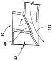
图10A-10D示出了作为一对棒的形式的另一个示例性辅助棒状组件10。辅助棒状组件10可包括第一气棒110和第二气棒112,它们被构造为分别围绕第一附接端部114和第二附接端部116相对于柜体16旋转至储存位置73a和使用位置73b或从这些位置开始旋转。以这种方式,第一气棒110和第二气棒112可垂直地对齐,以限定上部第一气棒110和下部第二气棒112。还可想到可将第一气棒110和第二气棒112构造为横向对齐。第一附接端部114和第二附接端部116可与柜体16旋转地耦合。根据所述装置的一些方面,外壳118设置在柜体16的侧部(例如,侧部16c)上。外壳118被构造为在不使用时接收或储存第一气棒110和第二气棒112,这总体上在图10B中示出。外壳118可与一个或多个辅助端口30流体连通。可选地,第一气棒110和第二气棒112各自直接与辅助端口30耦合。在所述装置的特定的方面中,第一气棒110和第二气棒112可相对于柜体16滑动地进行操作,以从其中伸出或缩回。10A-10D illustrate another exemplary
如图所示,第一气棒110和第二气棒112的第一附接端部114和第二附接端部116与柜体16附接或耦合。以这种方式,辅助棒状组件10被构造为形成在被限定在第一气棒110与第二气棒112之间的处理空间内延伸的气帘120。当第一气棒110和第二气棒112远离柜体16旋转时,第一气棒110和第二气棒112基本上定位为与地面平行。第一气棒110包括第一主体122并且第二气棒112包括第二主体124。第一主体122和第二主体124包括出口60。在使用期间,辅助空气18从出口60流出,从而在第一气棒110与第二气棒112之间形成气帘120。As shown, the
辅助棒状组件10还可包括挂钉34。挂钉34可适配诸如鞋类的服装。根据一些方面,第二气棒112可设置为比第一气棒110更低并且包括多个挂钉34,这些挂钩可间隔开并且向上延伸。可在辅助棒状组件10上包括任何合适数量的挂钉34。然而,辅助棒状组件10可以不包括挂钉34,这在图10C中示出。可选地,辅助棒状组件10可限定孔130,其被构造为接收用于将物品13悬挂在其上的衣架等等。替代地,物品13可被搭在第一气棒110和第二气棒112中的一个或两个上,以通过辅助空气18来烘干。The
在所述装置的特定的方面中,辅助空气18相对于第一气棒110和第二气棒112的流动可针对不同的功能进行构造和调节。辅助空气18可被引导为在从第一主体122和第二主体124向外的方向上流动。在这种构造中,辅助空气18用于烘干位于第一气棒110和第二气棒112中的每一个上的物品13。还可想到可将辅助空气18构造为相对于第一气棒110和第二气棒112中的一个在向外的方向上流动(正压流113)并且相对于第一气棒110和第二气棒112中的另一个被向内引导(抽吸111)。在这种构造中,辅助空气18在第一气棒110与第二气棒112之间形成了在向上的方向或向下的方向上流动的连续的气帘120。以这种方式,气帘120可用于引导气帘120穿过且围绕悬挂的物品。在这种构造中,气帘120可适于周期性地在向上流动与向下流动之间颠倒方向。第一气棒110和第二气棒112还可朝向彼此并且在处理空间内引导单独的气帘120。In certain aspects of the device, the flow of
图11A-11B示出了作为旋转棒形式的另一个示例性辅助棒状组件10。该辅助棒状组件10可类似于所述的两种辅助棒状组件10。该辅助棒状组件10包括单一的气棒140,其被构造为围绕附接的或上部的端部142进行摆动,该端部可与柜体16的侧部(例如,侧部16b)旋转地耦合。因此,辅助棒状组件10可从垂直定向的储存位置73a移动至水平定向的使用位置73b。在水平的使用位置73b中,自由端部143远离柜体16延伸。柜体16的侧部16b可包括被构造为用于接收并保持辅助棒状组件10的凹部144。气棒140包括出口60。根据一些方面,气棒140限定了开口146或孔,其被构造为用于接收将物品13悬挂在其上的衣架等等。开口146可在自由端部143处沿着气棒140的至少一部分长度延伸。11A-11B illustrate another exemplary
根据所述装置的多个方面,辅助棒状组件10可位于被限定在柜体16的表面内的容器78内的储存位置73a内。在所述装置的这个方面中,辅助棒状组件10通常可从外部看到。还可在视觉上对辅助棒状组件10进行隐藏或模糊,使其融入到柜体16的周围区域中。容器78还可被限定在柜体16的内部内。在所述装置的这个方面中,辅助棒状组件10可至少部分地缩回到柜体16内的区域。在这种构造中,辅助棒状组件10可具有可从外部看到的端件,而辅助棒状组件10的剩余部分被储存在柜体16内直到从容器78中伸出为止。According to aspects of the apparatus, the
现在参照图12,示出了根据本发明的多个方面的洗衣设备212。在一些例子中,洗衣设备212是垂直轴洗衣机,其包括可在升高位置211与降低位置213之间旋转的盖214,其中盖214选择性地覆盖出入口216。盖214可包括基本上平坦的或平面的下表面218。洗衣设备212还可包括面板220,其被构造为位于出入口216上或上方,以限定形成褶皱处理空间240的处理状态。面板220通常可进行移动或操作来移动到出入口216上方以及远离出入口216移动。面板220可包括基本上平面的上表面222。根据一些方面,面板220可选择性地附接至洗衣设备212并且可包括托盘式构造。此外,在所述装置的特定的方面中,面板220可与盖214的外框215集成在一起,使得外框215和面板220在下表面218与上表面222之间限定褶皱处理空间240。以这种方式,盖214使外框215和面板220形成铰接式构造,以允许使下表面218和上表面222以旋转方式进行分离,从而限定褶皱处理空间240。Referring now to FIG. 12 , there is shown a
在使用中,作为一个非限制性例子,下表面218和上表面222可彼此分离,从而在它们之间以及在褶皱处理空间240内插入物品13。在一个非限制性替代方案中,面板220可从盖214限定的储存空间217中移除,使得面板220可从盖214的储存空间317中滑出并且定位在出入口216上方。下表面218和上表面222可由任何合适的材料制成,包括但不限于玻璃、陶瓷、金属、多种聚合物、它们的组合以及其他类似的材料。In use, as a non-limiting example, the
根据一些方面,设置有导轨对接系统223,其可位于盖铰链区域附近。导轨对接系统223可选择性地将面板220对接或连接至洗衣设备212。导轨对接系统223可包括被构造为将面板220耦合至洗衣设备212的弹簧机构。还可想到面板220在对接时电气地耦合至洗衣设备212。以这种方式,面板220可利用电磁感应,使得在面板220与用于输送电力来加热面板220的组件之间可以不需要有线连接。According to some aspects, a
加热元件224被构造为对盖214的下表面218和面板220的上表面222中的至少一个进行加热。在一些方面中,盖214的下表面218和面板220的上表面222都被加热。在一些实施方式中,加热元件224包括通常为蒸汽形式的热水。在所述装置的这个方面中,盖214和顶部面板23中的至少一个可包括一个或多个蒸汽喷嘴,其可用于选择性地将一个或多个蒸汽射流引导到褶皱处理空间240上,从而帮助对洗衣物品13进行处理。The
在其他的实施方式中,加热元件224包括集成在盖214和/或面板220内的多条电感或电阻式导线226。另外,加热元件224可提供多种热量。褶皱处理空间240内使用的热量可通过加热元件224产生。还可想到用于褶皱处理空间240的至少一部分热量可从洗衣设备212的柜体16内输送到褶皱处理空间240中,或者来自于外部源,例如位于具有褶皱处理空间240的洗衣设备212附近的烘干设备。In other embodiments, the
盖214的下表面218和面板220的上表面222在盖214关闭时被按压在一起。以这种方式,盖214和面板220与熨斗或衣物夹类似地进行操作,以烘干并熨平物品13的褶皱。以这种方式,上表面222和下表面128基本上彼此平行。还可想到上表面222和下表面218中的至少一个可以能够符合位于褶皱处理空间240内的物品13的总体形状。在这种构造中,下表面218和/或上表面222可通过允许进行一些操作运动的可操作的连接件(例如球窝接头)分别附接至面板220和盖214,以限定褶皱处理空间240。The
使用洗衣设备212的盖214和面板220可减少或消除对额外的烘干程序的需求,例如单独的烘干、熨烫、刷新或蒸汽熨烫。洗衣设备212可包括流出通道230,其被构造为将从物品13去除的水引入到洗衣设备212的排水或循环管线中。Use of the
参照图13A和13B,示出了根据本发明的多个方面的洗衣设备312。在一些例子中,洗衣设备312是垂直轴洗衣机,其包括被结合在柜体16内的基部。柜体16还可放置在提升器314或底座上。提升器314被构造为将洗衣设备312从地面上抬高。抽屉或托盘316可设置在基部内并且可在位于基部内或提升器314内的存放位置315与位于柜体16前方的支撑位置317之间相对于柜体16伸缩。托盘316还可被构造为设置在提升器314内并且可相对于提升器314在柜体165下方的区域内进行伸缩。根据多个方面,台阶320设置在托盘316内。台阶320可包括承载用户的重量的平面的上表面322。在一些方面中,用户可向上拉动台阶320,以将台阶320从平坦位置319升高到台阶状位置321。Referring to Figures 13A and 13B, a
洗衣设备312可在托盘316的侧部上包括剪式铰链组件324,其被构造为将台阶320向上移动到台阶状位置321以及向下移动到平坦位置319。在平坦位置319中,托盘316被嵌套在托盘316内并且能够在存放位置315与支撑位置317之间进行操作。剪式铰链组件324(例如剪式连杆)可包括彼此交叉为“X”形的第一杆330和第二杆332。第一杆330和第二杆332可在它们的中部333处旋转地耦合。第一杆330和第二杆332各自的下端部334可相对于托盘316被固定在合适位置。第一杆330和第二杆332各自的上端部336可滑动地耦合至台阶320。如此,第一杆330和第二杆332可向上延伸至台阶状位置321以及向下延伸至平坦位置319。另外,剪式铰链组件324可包括锁定机构340,其被构造为将台阶320固定在台阶状位置321中,使得台阶320可被构造为承载用户的重量。
本文描述的多个方面的优点可包括被构造为在不使用传统的滚筒烘干程序的情况下烘干物品13并同时还巩固了洗衣区域中利用的空间的多个组件。因此,可减少或消除空气烘干时间。另外,作为集成在洗衣设备12中的台阶320形式的升高平台可使用户更容易够到洗衣设备12内的洗衣物品。Advantages of aspects described herein may include components configured to dry
根据本发明的另一个方面,一种洗衣设备包括柜体。鼓风机设置在柜体内,其用于输送辅助空气穿过辅助气流路径。辅助棒状组件与辅助气流路径流体连通。辅助棒状组件被构造为用于将物品悬挂在其上并且提供辅助空气来对物品进行调节。According to another aspect of the present invention, a laundry device includes a cabinet. A blower is arranged in the cabinet and is used to deliver auxiliary air through the auxiliary air flow path. The auxiliary wand assembly is in fluid communication with the auxiliary gas flow path. The auxiliary wand assembly is configured to suspend items thereon and to provide auxiliary air to condition the items.
根据另一个方面,辅助棒状组件为鞋类烘干器或悬挂式衣物烘干器的形式。According to another aspect, the auxiliary wand assembly is in the form of a shoe dryer or a hanging clothes dryer.
根据另一个方面,辅助气流路径包括换向阀,其选择性地将处理空气输送至辅助气流路径。According to another aspect, the auxiliary airflow path includes a reversing valve that selectively routes process air to the auxiliary airflow path.
根据本发明的另一个方面,鼓风机还引导处理空气穿过包含有滚筒的主气流路径。According to another aspect of the invention, the blower also directs process air through the main air flow path containing the drum.
根据另一个方面,辅助棒状组件从柜体的前部伸出。According to another aspect, the auxiliary wand assembly protrudes from the front of the cabinet.
根据另一个方面,在处理空间内引导辅助空气,处理空间位于柜体外部并且靠近前部。According to another aspect, the secondary air is guided in the processing space, which is located outside and close to the front of the cabinet.
根据本发明的另一个方面,辅助棒状组件包括多个孔,它们将来自辅助气流路径的辅助空气引入到处理空间中。According to another aspect of the present invention, the auxiliary bar assembly includes a plurality of holes that introduce auxiliary air from the auxiliary air flow path into the processing space.
根据另一个方面,辅助棒状组件包括上部第一气棒和下部第二气棒,它们分别连接至辅助气流路径。According to another aspect, the auxiliary rod assembly includes an upper first air rod and a lower second air rod respectively connected to the auxiliary air flow path.
根据另一个方面,上部第一气棒在向下的方向上将辅助空气引入到处理空间中。According to another aspect, the upper first air stick introduces secondary air into the treatment space in a downward direction.
根据本发明的另一个方面,下部第二气棒在向上的方向上将辅助空气引入到处理空间中。According to another aspect of the invention, the lower second air stick introduces auxiliary air into the treatment space in an upward direction.
根据另一个方面,辅助棒状组件能够从被限定在柜体内的容器中滑动地伸出。According to another aspect, the auxiliary wand assembly is slidably extendable from a receptacle defined within the cabinet.
根据另一个方面,容器被限定在柜体的外表面内。According to another aspect, the container is defined within the exterior surface of the cabinet.
根据本发明的另一个方面,容器被限定在柜体的内部中。According to another aspect of the invention, the container is defined within the interior of the cabinet.
根据另一个方面,一种垂直轴洗衣机包括具有顶部面板的柜体,顶部面板限定了出入口。盖与顶部面板耦合并且具有下表面。盖能够在位于出入口上方的升高位置与覆盖出入口的降低位置之间进行操作。可移除面板选择性地位于顶部面板上并且跨过出入口,以限定处理状态。加热元件位于盖与顶部面板中的至少一个的附近。加热元件被构造为对盖的下表面和可移除面板的上表面中的至少一个进行加热。当可移除面板处于处理状态并且盖处于降低位置时,盖的下表面和可移除面板的上表面被按压在一起来限定用于对衣物进行处理的褶皱处理空间。According to another aspect, a vertical axis washing machine includes a cabinet having a top panel defining an access opening. A cover is coupled to the top panel and has a lower surface. The cover is operable between a raised position over the access opening and a lowered position covering the access opening. A removable panel is optionally located on the top panel and across the doorway to define the treatment status. A heating element is located adjacent to at least one of the lid and the top panel. The heating element is configured to heat at least one of the lower surface of the cover and the upper surface of the removable panel. When the removable panel is in the processing state and the cover is in the lowered position, the lower surface of the cover and the upper surface of the removable panel are pressed together to define a crease processing space for processing the laundry.
根据另一个方面,盖和顶部面板中的一个包括蒸汽喷嘴,其选择性地将蒸汽射流引入到褶皱处理空间中。According to another aspect, one of the lid and the top panel includes a steam nozzle that selectively introduces a jet of steam into the pleat processing volume.
根据本发明的另一个方面,盖包括平面的下表面并且可移除面板包括平面的上表面。当可移除面板处于处理状态并且盖处于降低位置时平面的下表面和平面的上表面平行。According to another aspect of the invention, the cover includes a planar lower surface and the removable panel includes a planar upper surface. The planar lower surface and the planar upper surface are parallel when the removable panel is in the handling state and the cover is in the lowered position.
根据另一个方面,盖的下表面能够相对于盖的外框进行操作。盖的下表面被构造为在处理状态下与可移除面板的上表面一致。According to another aspect, the lower surface of the cover is operable relative to the outer frame of the cover. The lower surface of the cover is configured to conform to the upper surface of the removable panel in the handling state.
根据另一个方面,加热元件在盖内位于盖的下表面与盖的外框之间。According to another aspect, the heating element is located within the cover between the lower surface of the cover and the outer frame of the cover.
根据本发明的另一个方面,一种垂直轴洗衣机包括柜体,其具有位于柜体的下部附近的基部。抽屉设置在基部内并且能够在位于基部内的存放位置与位于基部前方的支撑位置之间进行操作。台阶设置在抽屉内。台阶通过剪式连杆附接至抽屉。台阶被构造为当抽屉处于支撑位置时能够在平坦位置与台阶状位置之间进行操作。According to another aspect of the invention, a vertical axis washing machine includes a cabinet having a base located near a lower portion of the cabinet. A drawer is disposed within the base and is operable between a storage position within the base and a support position forward of the base. The steps are set in the drawer. The steps are attached to the drawers by scissor links. The step is configured to be operable between a flat position and a stepped position when the drawer is in the support position.
根据另一个方面,基部是与柜体分开的底座。底座从下方支撑柜体。According to another aspect, the base is a plinth separate from the cabinet. The plinth supports the cabinet from below.
本领域一般技术人员将会理解,所述公开内容和其他部件的构造并非限制于任何特定的材料。除非本文另有说明,否则可以通过多种材料来形成本文公开的公开内容的其他的示例性实施方式。Those of ordinary skill in the art will appreciate that the disclosure and construction of other components are not limited to any particular material. Other exemplary embodiments of the disclosure disclosed herein can be formed from a variety of materials, unless otherwise indicated herein.
针对本发明,词语“耦合”(以及其所有形式,被耦合、耦合至等等)主要表示两个部件直接或间接地(电气地或机械地)彼此连接。这种连接在本质上可以是固定的或者本质上是可动的。这种连接可通过两个部件(电气地或机械地)以及彼此之间或与这两个部件一体形成为单一整体的任何额外的中间构件来实现。这种连接本质上可以是永久的或者本质上是可分离或可移除的,除非另有说明。For purposes of the present invention, the word "coupled" (and all forms thereof, coupled, coupled to, etc.) primarily means that two components are connected to each other, directly or indirectly (electrically or mechanically). Such connections may be fixed in nature or movable in nature. This connection may be through the two components (electrically or mechanically) and any additional intermediate members formed between each other or integrally with the two components as a single body. Such connections may be permanent in nature or detachable or removable in nature unless otherwise stated.
另外重要的是应注意示例性实施方式中示出的公开内容的元件的构造和布置仅仅是说明性的。尽管在本发明中仅详细描述了本发明创造的一些实施方式,但是研究了本发明的本领域技术人员将容易地理解的是在没有实质上脱离所述主题的新颖教导和优点的情况下可以做出许多修改(例如,改变大小、尺寸、结构、形状和多个元件的比例、参数值、安装布置、材料的使用、颜色、取向等等)。例如,被表示为一体形成的元件可被构造为多个部分,或者被表示为多个部分的元件可以一体形成,接口的操作可以颠倒或改变,结构和/或系统的构件或连接器或其他元件的长度或宽度可以变化,元件之间提供的调节位置的特征或数量可以变化。应注意,系统的元件和/或组件可通过提供足够的强度或耐久性的多种材料中的任何一种来构造、被构造为多种颜色、质地和它们的组合中的任何一种。因此,所有这些修改都应被包括在本发明创造的范围之内。可在不脱离本发明创造的精神的情况下在所需的和其他的示例性实施方式的设计、操作状态和布置方面做出其他的替换、修改、变更和省略。It is also important to note that the construction and arrangement of elements of the disclosure shown in the exemplary embodiments are illustrative only. Although only a few embodiments of the inventive invention have been described in detail herein, those skilled in the art who study the disclosure will readily appreciate that the novel teachings and advantages of the subject matter can be described without materially departing from the novel teachings and advantages of the subject matter. Many modifications are made (eg, changes in size, dimension, structure, shape and proportion of various elements, parameter values, mounting arrangements, use of materials, colors, orientations, etc.). For example, elements represented as integrally formed may be constructed in multiple parts, or elements represented as multiple parts may be formed integrally, the operation of interfaces may be reversed or changed, structural and/or system components or connectors or other The length or width of the elements may vary, and the nature or number of adjustment positions provided between the elements may vary. It should be noted that the elements and/or assemblies of the system may be constructed of any of a variety of materials, in any of a variety of colors, textures, and combinations thereof that provide sufficient strength or durability. Therefore, all such modifications should be included within the scope of the present invention. Other substitutions, modifications, changes and omissions may be made in the design, operating conditions and arrangement of desired and other exemplary embodiments without departing from the spirit of the inventive concept.
应理解,任何所述的程序或所述程序中的任何步骤都可以与所公开的其他的程序或步骤组合形成本发明的范围内的结构。本文公开的示例性结构和程序的目的在于说明,不应被解释为限制性的。It will be understood that any described procedure, or any step within a described procedure, may be combined with other disclosed procedures or steps to form structures within the scope of the invention. The exemplary structures and procedures disclosed herein are for purposes of illustration and should not be construed as limiting.
Claims (20)
Applications Claiming Priority (4)
| Application Number | Priority Date | Filing Date | Title |
|---|---|---|---|
| US202163183205P | 2021-05-03 | 2021-05-03 | |
| US63/183,205 | 2021-05-03 | ||
| US17/723,612 US12534846B2 (en) | 2021-05-03 | 2022-04-19 | Laundry appliance having laundry accessories |
| US17/723,612 | 2022-04-19 |
Publications (1)
| Publication Number | Publication Date |
|---|---|
| CN115369619A true CN115369619A (en) | 2022-11-22 |
Family
ID=81448502
Family Applications (1)
| Application Number | Title | Priority Date | Filing Date |
|---|---|---|---|
| CN202210470948.8A Pending CN115369619A (en) | 2021-05-03 | 2022-04-28 | Laundry appliance with laundry accessories |
Country Status (3)
| Country | Link |
|---|---|
| US (1) | US12534846B2 (en) |
| EP (1) | EP4095309A3 (en) |
| CN (1) | CN115369619A (en) |
Family Cites Families (35)
| Publication number | Priority date | Publication date | Assignee | Title |
|---|---|---|---|---|
| US3926315A (en) | 1975-01-10 | 1975-12-16 | Gen Motors Corp | Add-on clothes hanger for appliance |
| US4003138A (en) | 1975-09-23 | 1977-01-18 | Wicks Wayne M | Air curtain for clothes dryer |
| DE3211316A1 (en) | 1982-03-26 | 1983-09-29 | August Lepper GmbH, 5340 Bad Honnef | Domestic appliance, in particular washing machine or laundry dryer |
| JPH01145099A (en) | 1987-11-30 | 1989-06-07 | Toshiba Corp | Washing machine |
| KR920008257A (en) | 1990-10-23 | 1992-05-27 | 강진구 | Ironing board built-in washing machine |
| US5181685A (en) | 1991-10-09 | 1993-01-26 | Vladimir Ostapowicz | Collapsible hanger bar |
| JPH07213792A (en) | 1994-02-04 | 1995-08-15 | Inax Corp | Temporary drying tool |
| JP3600106B2 (en) | 2000-03-01 | 2004-12-08 | 株式会社日立製作所 | Clothes dryer |
| US20070266740A9 (en) * | 2000-07-25 | 2007-11-22 | Kendall James W | Vertical laundry module |
| DE10259346A1 (en) | 2002-12-18 | 2004-07-08 | BSH Bosch und Siemens Hausgeräte GmbH | Device for drying laundry items in connection with a condensation household clothes dryer |
| CA2475811A1 (en) | 2003-08-18 | 2005-02-18 | Jean-Pierre Deblois | Handwear and footwear dryer rack with removable portable heater |
| US20070151304A1 (en) | 2005-12-30 | 2007-07-05 | Kendall James W | Modular laundry system with work surface having a functional insert |
| KR100662369B1 (en) * | 2004-11-30 | 2007-01-02 | 엘지전자 주식회사 | Combination Dryer with Hot Air Hanger |
| US7954914B2 (en) | 2005-12-30 | 2011-06-07 | Whirlpool Corporation | Retractable hanging element |
| ATE403771T1 (en) | 2006-03-17 | 2008-08-15 | Electrolux Home Prod Corp | HOUSEHOLD MACHINE FOR WASHING OR DRYING LAUNDRY. |
| EP1854916B1 (en) | 2006-05-09 | 2009-07-15 | Electrolux Home Products Corporation N.V. | Household appliance |
| KR20090102416A (en) | 2008-03-26 | 2009-09-30 | 엘지전자 주식회사 | Laundry machine |
| EP2194184A1 (en) | 2008-12-04 | 2010-06-09 | Electrolux Home Products Corporation N.V. | Device for drying shoes exploiting a laundry drying household appliance |
| PL2957671T3 (en) | 2009-06-29 | 2019-03-29 | Electrolux Home Products Corporation N.V. | Appliance for drying laundry |
| US8595952B2 (en) | 2010-06-30 | 2013-12-03 | Whirlpool Corporation | Integrated hanging solution |
| DE102011002330B3 (en) | 2011-04-29 | 2012-01-26 | Miele & Cie. Kg | Device for providing shirt at washing machine, has holder comprising bent area placed at upper edge of housing of laundry treatment machine, and bearing arranged at swingable support of arm that is swung into position of work area of holder |
| US20120293052A1 (en) | 2011-05-16 | 2012-11-22 | Bsh Home Appliances Corporation | Work top and household appliance having a laundry hanging device |
| US8578639B2 (en) | 2011-06-27 | 2013-11-12 | Andrew C. Hurd | Fabric press |
| CN102677418A (en) | 2012-05-09 | 2012-09-19 | 南京乐金熊猫电器有限公司 | Washing machine |
| KR102146019B1 (en) | 2013-08-01 | 2020-08-20 | 삼성전자주식회사 | washing machine having a dry apparatus |
| KR102196313B1 (en) * | 2014-08-12 | 2020-12-29 | 엘지전자 주식회사 | cloth treating apparatus |
| KR102611054B1 (en) | 2016-07-07 | 2023-12-07 | 엘지전자 주식회사 | Laundry Treating Apparatus |
| CN105970564A (en) | 2016-07-26 | 2016-09-28 | 赵忠华 | Clothesline pole with hanger clamping and temperature control functions |
| KR102747180B1 (en) | 2016-12-08 | 2024-12-27 | 삼성전자주식회사 | Clothes dryer |
| CN106835606A (en) | 2016-12-30 | 2017-06-13 | 惠而浦(中国)股份有限公司 | Cumulative top cover drying washing machine |
| US10100459B2 (en) | 2017-01-06 | 2018-10-16 | Whirlpool Corporation | Flexible drying solution for delivering clothing care externally of a drying appliance |
| EP3284856A1 (en) | 2017-12-01 | 2018-02-21 | V-Zug AG | Drum and room air dryer with an assembly device |
| CN110878468B (en) | 2018-09-05 | 2022-03-01 | 广东美的白色家电技术创新中心有限公司 | Clothes care equipment and control method thereof |
| US10774464B2 (en) | 2018-09-12 | 2020-09-15 | Haier Us Appliance Solutions, Inc. | Laundry appliance having an ironing assembly |
| US11767633B2 (en) | 2019-07-01 | 2023-09-26 | Whirlpool Corporation | Drying appliance having an accessory port for providing external airflow for powered accessories |
-
2022
- 2022-04-19 US US17/723,612 patent/US12534846B2/en active Active
- 2022-04-28 CN CN202210470948.8A patent/CN115369619A/en active Pending
- 2022-04-29 EP EP22170986.8A patent/EP4095309A3/en not_active Withdrawn
Also Published As
| Publication number | Publication date |
|---|---|
| EP4095309A2 (en) | 2022-11-30 |
| US12534846B2 (en) | 2026-01-27 |
| US20220349111A1 (en) | 2022-11-03 |
| EP4095309A3 (en) | 2023-03-01 |
Similar Documents
| Publication | Publication Date | Title |
|---|---|---|
| US20080222909A1 (en) | Drying apparatus | |
| RU2401348C2 (en) | Ironing board with inclined platform | |
| CN101657581B (en) | Auxiliary laundry treating machine and multiple treating system including the same | |
| EP3118368B1 (en) | Clothes dryer | |
| US2463218A (en) | Drier | |
| US20020133969A1 (en) | Air-flow dryer and method | |
| US20130263465A1 (en) | Dryer-hanger single-body machine | |
| CN101213336B (en) | Ironing board having an extendable and retractable base | |
| WO2007128358A1 (en) | Household appliance | |
| CN107002345A (en) | Vertical steam Garment Steamer Machine | |
| US20060137211A1 (en) | Garment drying cabinet and system | |
| KR102132154B1 (en) | Steam care device for clothes | |
| CN109790676B (en) | clothes dryer | |
| CN115369619A (en) | Laundry appliance with laundry accessories | |
| CN101213337B (en) | height-adjustable ironing board | |
| KR20100096388A (en) | Dryer | |
| KR101822379B1 (en) | Laundry dryer having space storage dryer | |
| KR20110084006A (en) | Dressing table with ironing board | |
| KR100595240B1 (en) | Combined dryer with laundry folding means | |
| KR20160019729A (en) | cloth treating apparatus | |
| CN107345361A (en) | A kind of intelligent clothing care machine | |
| EP3415678B1 (en) | Secondary drying chamber for a clothes dryer | |
| US20130180123A1 (en) | Appliance having a drying rack | |
| US1449609A (en) | Drier | |
| CN206396515U (en) | A kind of dryer |
Legal Events
| Date | Code | Title | Description |
|---|---|---|---|
| PB01 | Publication | ||
| PB01 | Publication | ||
| SE01 | Entry into force of request for substantive examination | ||
| SE01 | Entry into force of request for substantive examination |