CN115311358A - Long-distance continuous pose high-speed video measurement method - Google Patents
Long-distance continuous pose high-speed video measurement method Download PDFInfo
- Publication number
- CN115311358A CN115311358A CN202210799215.9A CN202210799215A CN115311358A CN 115311358 A CN115311358 A CN 115311358A CN 202210799215 A CN202210799215 A CN 202210799215A CN 115311358 A CN115311358 A CN 115311358A
- Authority
- CN
- China
- Prior art keywords
- distance
- long
- observation
- speed video
- depth
- Prior art date
- Legal status (The legal status is an assumption and is not a legal conclusion. Google has not performed a legal analysis and makes no representation as to the accuracy of the status listed.)
- Pending
Links
Images


Classifications
-
- G—PHYSICS
- G06—COMPUTING OR CALCULATING; COUNTING
- G06T—IMAGE DATA PROCESSING OR GENERATION, IN GENERAL
- G06T7/00—Image analysis
- G06T7/70—Determining position or orientation of objects or cameras
- G06T7/73—Determining position or orientation of objects or cameras using feature-based methods
-
- G—PHYSICS
- G06—COMPUTING OR CALCULATING; COUNTING
- G06T—IMAGE DATA PROCESSING OR GENERATION, IN GENERAL
- G06T7/00—Image analysis
- G06T7/80—Analysis of captured images to determine intrinsic or extrinsic camera parameters, i.e. camera calibration
- G06T7/85—Stereo camera calibration
Landscapes
- Engineering & Computer Science (AREA)
- Computer Vision & Pattern Recognition (AREA)
- Physics & Mathematics (AREA)
- General Physics & Mathematics (AREA)
- Theoretical Computer Science (AREA)
- Length Measuring Devices By Optical Means (AREA)
Abstract
Description
技术领域technical field
本发明涉及航天工程模型动态参数测量技术,尤其是涉及一种长距离连续位姿高速视频测量方法。The invention relates to a dynamic parameter measurement technology of an aerospace engineering model, in particular to a long-distance continuous pose high-speed video measurement method.
背景技术Background technique
随着航天工程的迅速发展,在地面验证测试实验中长距离连续位置姿态参数的高精度测量已成为前沿研究课题。采用传统接触式测量手段,如将位移计、加速度计、应变片等接触式传感器固定在测量目标对象表面以获取位移、加速度、应变等信息,这类方法存在量程有限、测量区域小甚至会破坏模型结构等缺陷。为了克服上述缺陷,以相机和激光传感器为代表的非接触式传感器被采用,其中激光技术又存在测点单一、价格昂贵、采集频率低等缺陷,因此使用相机详细记录运动物体的变化状态,然后通过摄影测量解析方法精确地测量目标特征点的三维空间坐标变化及其三维形变,从而获取待测物体的动态参数的测量方式被更广泛应用。With the rapid development of aerospace engineering, the high-precision measurement of long-distance continuous position and attitude parameters in ground verification test experiments has become a frontier research topic. Using traditional contact measurement methods, such as fixing contact sensors such as displacement meters, accelerometers, and strain gauges on the surface of the measurement target to obtain information such as displacement, acceleration, and strain, such methods have limited range, small measurement areas, and even damage. Model structure and other defects. In order to overcome the above defects, non-contact sensors represented by cameras and laser sensors are adopted, and laser technology has defects such as single measuring point, high price, and low acquisition frequency. Therefore, the camera is used to record the changing state of the moving object in detail, and then The measurement method of obtaining the dynamic parameters of the object to be measured is more widely used by accurately measuring the three-dimensional space coordinate change and three-dimensional deformation of the target feature point through the photogrammetry analysis method.
在航天工程模型动态参数测量过程中,由于目标在深度方向的移动过程较长,目标相对于相机在不同观测段间的相对距离存在差异,当前普遍采用多相机分段观测单独计算长距离连续位姿,导致整体定位精度较低且在远距离时观测精度不一致的问题。In the process of measuring dynamic parameters of aerospace engineering models, due to the long moving process of the target in the depth direction, the relative distance between the target and the camera in different observation segments is different. attitude, resulting in low overall positioning accuracy and inconsistent observation accuracy at long distances.
发明内容Contents of the invention
本发明的目的就是为了克服上述现有技术存在的缺陷而提供一种长距离连续位姿高速视频测量方法。The purpose of the present invention is to provide a long-distance continuous pose high-speed video measurement method in order to overcome the above-mentioned defects in the prior art.
本发明的目的可以通过以下技术方案来实现:The purpose of the present invention can be achieved through the following technical solutions:
根据本发明的一个方面,提供了一种长距离连续位姿高速视频测量方法,该方法包括以下步骤:According to one aspect of the present invention, a long-distance continuous pose high-speed video measurement method is provided, the method comprising the following steps:
步骤1,采用多双目连续观测联合光束法平差对观测值进行解算;Step 1, using multi-binocular continuous observation joint beam adjustment to solve the observation value;
步骤2,采用深度距离和平差残差约束的自适应变权策略对步骤1)的解算过程进行处理,得到连续位姿参数测量结果;Step 2, using the adaptive variable weight strategy of depth distance and difference residual constraints to process the solution process of step 1), and obtain continuous pose parameter measurement results;
步骤3,采用基于平面拟合的位置姿态参数动态反演对步骤2)得到的连续位姿参数测量结果进行优化。In step 3, the continuous pose parameter measurement results obtained in step 2) are optimized by using the dynamic inversion of position and pose parameters based on plane fitting.
作为优选的技术方案,所述的步骤1,多双目连续观测联合光束法平差过程具体为:As a preferred technical solution, the step 1, multi-binocular continuous observation joint beam adjustment process is specifically:
101,在摄影测量学中,利用最小二乘原理使得反投影与原始像点距离残差累积平方和最小,按如下最小二乘问题的形式表达为:101. In photogrammetry, the principle of least squares is used to minimize the cumulative sum of squares of the residual distance between the back projection and the original image point, which is expressed in the form of the following least squares problem:

其中(ui,j,vi,j)为第i台相机所拍摄的像平面上实际观测得到第j个三维点含有畸变的像素坐标;π(Cami,Pj)=(u(i,j)distorted,v(i,j)distorted),即表示物方空间第j个三维点经第i台相机的内外方矩阵透视变换后,并且考虑该相机镜头畸变参数偏移后所得到的反投影像素坐标,e、m、n分别为反投影残差、相机数量和三维点数量;Where (u i,j ,v i,j ) is the pixel coordinate of the jth three-dimensional point with distortion obtained from the actual observation on the image plane captured by the i-th camera; π(Cam i ,P j )=(u (i ,j)distorted ,v (i,j)distorted ), which means that the jth three-dimensional point in the object space is transformed by the perspective transformation of the inner and outer square matrix of the i-th camera, and the lens distortion parameter offset of the camera is taken into account. Backprojection pixel coordinates, e, m, n are the backprojection residual, the number of cameras and the number of 3D points respectively;
102,利用公式(1)对长距离连续位姿解算过程描述为多个独立的光束法平差过程,其表达式改为:102. Use formula (1) to describe the long-distance continuous pose calculation process as multiple independent beam adjustment processes, and the expression is changed to:
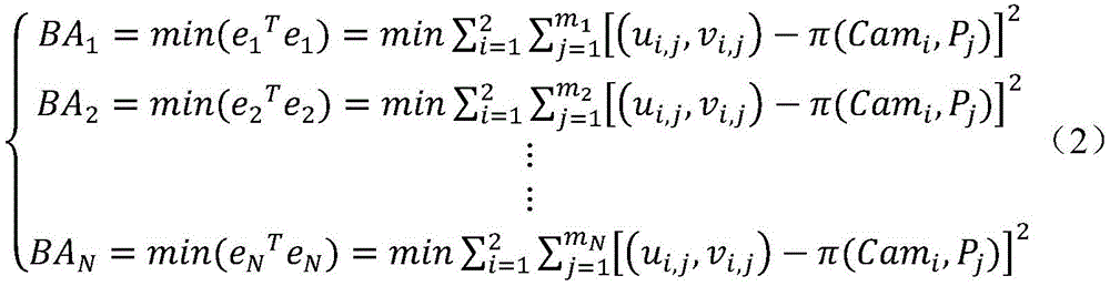
其中BAk表示第k段局部光束法平差过程,mk分别表示第k段双目视觉测量系统中的相机集合与观测的物方三维点集。Among them, BA k represents the local beam adjustment process of the k-th segment, and m k represents the camera set and the observed object-space 3D point set in the binocular vision measurement system of the k-th segment, respectively.
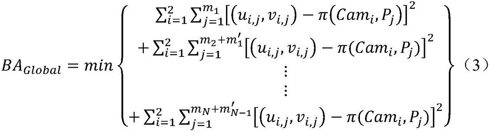
103,采用联合光束法平差解算通过公式(2)进行改进得到:103, using the joint beam method to adjust the solution and improve the formula (2) to obtain:

其中m′k-1表示第k段双目视觉测量系统中相机观测到与第k-1段双目视觉测量系统中重复的物方三维点集,BAGlobal表示联合光束法平差过程。Among them, m′ k-1 represents the object-space three-dimensional point set repeated by the camera in the binocular vision measurement system of the k-th segment and repeated in the binocular vision measurement system of the k-1 segment, and BA Global represents the joint beam adjustment process.
作为优选的技术方案,所述的步骤2中的深度距离和平差残差约束的自适应变权策略包括引入迭代重加权和在平差过程中引入深度变化加权策略。As a preferred technical solution, the adaptive weighting strategy for depth distance and adjustment residual constraints in step 2 includes introducing iterative reweighting and introducing a depth change weighting strategy in the adjustment process.
作为优选的技术方案,所述的引入迭代重加权为:在光束法平差优化迭代求解中不断调整某次观测值的权值。As a preferred technical solution, the introduction of iterative reweighting is: continuously adjusting the weight of a certain observation value in the iterative solution of bundle adjustment optimization optimization.
作为优选的技术方案,所述的在光束法平差优化迭代求解中不断调整某次观测值的权值具体为:As a preferred technical solution, the weight of constantly adjusting a certain observation value in the iterative solution of beam adjustment optimization optimization is specifically:
基于Huber鲁棒损失函数,在每次迭代优化前对某一观测值进行如下的迭代重加权操作:Based on the Huber robust loss function, the following iterative reweighting operation is performed on an observation value before each iteration optimization:

其中wr(k)表示第k次观测值迭代重加的鲁棒权重,rk表示第k次观测值经误差方程计算得到的反投影误差的二范数,即rk=‖ek‖2,δ表示异常点阈值。where w r(k) represents the robust weight iteratively added to the k-th observation value, and r k represents the bi-norm of the back-projection error calculated by the error equation for the k-th observation value, that is, r k =‖e k ‖ 2 , δ represents the outlier threshold.
作为优选的技术方案,所述的异常点阈值取值为0.001。As a preferred technical solution, the abnormal point threshold value is 0.001.
作为优选的技术方案,所述的在平差过程中引入深度变化加权策略为:对不同深度的观测值依照其与双目视觉系统基线间深度距离的倒数作为定权依据,以充分考虑由于目标点深度值较大导致观测精度降低的客观事实。As a preferred technical solution, the introduction of the depth change weighting strategy in the adjustment process is as follows: the reciprocal of the depth distance between the observed values at different depths and the baseline of the binocular vision system is used as the weighting basis to fully consider the It is an objective fact that the larger point depth value leads to lower observation accuracy.
作为优选的技术方案,所述的定权方式具体为:As a preferred technical solution, the described way of determining the weight is specifically:
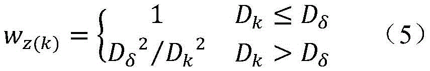
其中wz(k)表示第k次观测值的深度变化权重,Dk表示第k次观测值与双目视觉系统基线间的深度距离,Dδ表示深度距离阈值,上式表明仅对特定深度范围之外的观测进行权重修正。where w z(k) represents the depth change weight of the k-th observation, D k represents the depth distance between the k-th observation and the baseline of the binocular vision system, and D δ represents the depth distance threshold. The above formula shows that only for a specific depth Observations outside the range are weighted.
作为优选的技术方案,将所述Dδ设定为两台相机光轴空间交点处至双目视觉系统基线间的深度距离,该距离能够较容易地通过两台相机的初始参数交会计算得到。As a preferred technical solution, the D δ is set as the depth distance between the spatial intersection of the optical axes of the two cameras and the baseline of the binocular vision system, and this distance can be easily calculated by the intersection of the initial parameters of the two cameras.
作为优选的技术方案,所述的步骤3具体为:As a preferred technical solution, described step 3 is specifically:
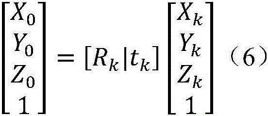
以参考初始状态下给定的四个人工标志的三维坐标为基准,拟合平面每一时刻相对于初始状态的旋转与平移变化关系可由四个标志点间的刚体变换关系表示为:With reference to the three-dimensional coordinates of the four artificial markers given in the initial state, the relationship between the rotation and translation of the fitting plane relative to the initial state at each moment can be expressed by the rigid body transformation relationship between the four marker points as:

其中Rk和tk分别为k时刻模型表面相对于参考初始状态的平移和旋转参数,X0、Y0、Z0、Xk、Yk、Zk分别为参考初始状态和k时刻的三维坐标。where R k and t k are the translation and rotation parameters of the model surface relative to the reference initial state at time k, respectively, and X 0 , Y 0 , Z 0 , X k , Y k , and Z k are the three-dimensional coordinate.
与现有技术相比,本发明能够实现长距离移动目标动态位置姿态参数的高精度连续测量,测量定位精度优于3mm,相比国际著名视觉测量软件精度提升了超30%。Compared with the prior art, the present invention can realize high-precision continuous measurement of the dynamic position and attitude parameters of long-distance moving targets, and the measurement and positioning accuracy is better than 3mm, which is more than 30% higher than that of internationally renowned visual measurement software.
附图说明Description of drawings
图1为联合光束法平差方法示意图;Figure 1 is a schematic diagram of the joint bundle adjustment method;
图2为基于平面拟合的位置姿态参数动态反演示意图;Figure 2 is a schematic diagram of dynamic inversion of position and attitude parameters based on plane fitting;
图3为多双目视觉测量系统布设示意图;Figure 3 is a schematic diagram of the layout of the multi-binocular vision measurement system;
图4为空间三维控制场布设方法示意图;Fig. 4 is a schematic diagram of a method for laying out a three-dimensional control field in space;
图5为上仰20°位姿参数解算结果示意图;Fig. 5 is a schematic diagram of the calculation results of the pose parameters at 20° upward;
图6为右偏20°位姿参数解算结果示意图;Figure 6 is a schematic diagram of the calculation results of the pose parameters at 20° to the right;
图7为左右章动位姿参数解算结果示意图。Fig. 7 is a schematic diagram of the calculation results of left and right nutation pose parameters.
具体实施方式Detailed ways
下面将结合本发明实施例中的附图,对本发明实施例中的技术方案进行清楚、完整地描述,显然,所描述的实施例是本发明的一部分实施例,而不是全部实施例。基于本发明中的实施例,本领域普通技术人员在没有做出创造性劳动的前提下所获得的所有其他实施例,都应属于本发明保护的范围。The following will clearly and completely describe the technical solutions in the embodiments of the present invention with reference to the drawings in the embodiments of the present invention. Obviously, the described embodiments are part of the embodiments of the present invention, not all of them. Based on the embodiments of the present invention, all other embodiments obtained by persons of ordinary skill in the art without making creative efforts shall fall within the protection scope of the present invention.
1.本发明概况1. Outline of the invention
随着航天工程的迅速发展,在地面验证测试实验中高精度测量航天模型的动态位姿参数已成为前沿的研究课题。为满足长距离连续位姿参数的高精度非接触式测量需求,提出了一种自适应变权联合光束法平差的长距离连续位姿估计方法。采用自适应变权最小二乘平差策略的多双目视觉测量系统长距离连续观测联合光束法平差方法,并结合基于平面拟合的位置姿态参数动态反演技术,优化动态参数测量结果的精度。为了验证提出长距离位姿参数测量方法的可靠性,本专利开展了卫星交会对接地面测试高速视频位姿测量实验,实验结果表明使用本专利所提出的测量方法能够实现长距离移动目标动态位置姿态参数的高精度连续测量,测量定位精度优于3mm,相比国际著名视觉测量软件精度提升了超30%。With the rapid development of aerospace engineering, it has become a frontier research topic to measure the dynamic pose parameters of aerospace models with high precision in ground verification test experiments. In order to meet the high-precision non-contact measurement requirements of long-distance continuous pose parameters, a long-distance continuous pose estimation method based on adaptive variable weight combined with beam adjustment is proposed. The multi-binocular vision measurement system long-distance continuous observation joint beam adjustment method adopts the adaptive variable weight least squares adjustment strategy, and combines the dynamic inversion technology of position and attitude parameters based on plane fitting to optimize the accuracy of dynamic parameter measurement results. precision. In order to verify the reliability of the proposed long-distance pose parameter measurement method, this patent carried out a satellite rendezvous and ground test high-speed video pose measurement experiment. The experimental results show that using the measurement method proposed in this patent can realize the dynamic position and attitude of long-distance moving targets High-precision continuous measurement of parameters, measurement and positioning accuracy is better than 3mm, which is more than 30% higher than that of internationally renowned visual measurement software.
2、长距离连续位姿高速视频测量方法2. Long-distance continuous pose high-speed video measurement method
本专利提出的长距离连续位姿高速视频测量方法主要包括深度距离和平差残差约束定权的长距离连续观测联合光束法平差方法以及基于平面拟合的位置姿态参数动态反演两大部分。The long-distance continuous pose high-speed video measurement method proposed in this patent mainly includes two parts: the depth distance and the residual constraint weighting of the long-distance continuous observation combined beam adjustment method and the dynamic inversion of position and attitude parameters based on plane fitting. .
2.1多双目连续观测联合光束法平差2.1 Multi-binocular continuous observation joint beam adjustment
在摄影测量学中,利用最小二乘原理使得反投影与原始像点距离残差累积平方和最小,即反投影误差平方和最小,该方法被为光束法平差(Bundle Adjustment),可按如下最小二乘问题的形式表达为:In photogrammetry, the least squares principle is used to minimize the cumulative sum of squares of the distance between the back projection and the original image point, that is, the smallest sum of squares of the back projection error. This method is called Bundle Adjustment, which can be as follows The form of the least squares problem is expressed as:

式中,(ui,j,vi,j)为第i台相机所拍摄的像平面上实际观测得到第j个三维点含有畸变的像素坐标;π(Cami,Pj)=(u(i,j)distorted,v(i,j)distorted),即表示物方空间第j个三维点经第i台相机的内外方矩阵透视变换后,并且考虑该相机镜头畸变参数偏移后所得到的反投影像素坐标。In the formula, (u i,j ,v i,j ) is the distorted pixel coordinates of the jth three-dimensional point actually observed on the image plane captured by the i-th camera; π(Cam i ,P j )=(u (i,j)distorted ,v (i,j)distorted ), which means that the jth 3D point in the object space is transformed by the perspective transformation of the inner and outer square matrix of the i-th camera, and the lens distortion parameter offset of the camera is considered. The resulting backprojected pixel coordinates.
在长距离连续位姿测量中,传统普遍采用的多相机分段测量法是以各段双目视觉测量系统的观测为单独的计算单元,在各段观测范围内进行局部光束法平差以获取立体相机的外参和待测目标点的空间三维信息,最终将各段处理结果进行拼接从而获得长距离全过程的解算结果,利用公式2.1可将上述解算过程描述为多个独立的光束法平差过程:In the long-distance continuous pose measurement, the traditionally commonly used multi-camera segmental measurement method uses the observation of each segment of the binocular vision measurement system as a separate calculation unit, and performs local beam adjustment in each segment of the observation range to obtain The external parameters of the stereo camera and the spatial three-dimensional information of the target point to be measured are finally stitched together to obtain the long-distance whole-process calculation results. The above-mentioned calculation process can be described as multiple independent beams by using formula 2.1 Normal adjustment process:
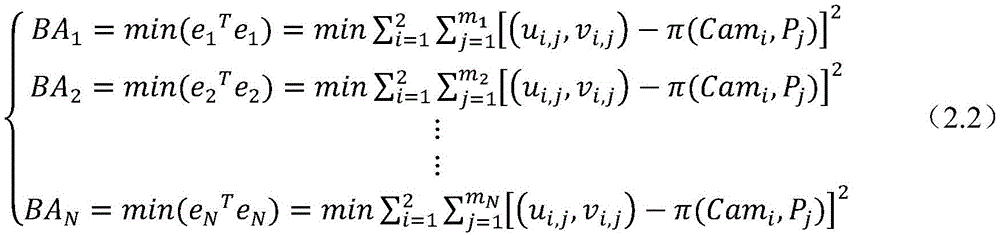
式中BAk表示第k段局部光束法平差过程,mk分别表示第k段双目视觉测量系统中的相机集合与观测的物方三维点集。采用该解算方式会造成单独立体像对间的位姿相互独立,无法保证其在空间整体坐标系下与实际相对位姿相符,导致解算得到的待测目标点空间三维信息缺乏整体性,会出现全局结果拼接时的不连续,最终使结算结果不具鲁棒性。In the formula, BA k represents the local beam adjustment process of the k-th segment, and m k represents the camera set and the observed object-space 3D point set in the binocular vision measurement system of the k-th segment, respectively. The use of this calculation method will cause the poses of the individual stereo pairs to be independent of each other, and it cannot be guaranteed that they are consistent with the actual relative poses in the overall space coordinate system, resulting in a lack of integrity in the spatial three-dimensional information of the target points to be measured. There will be discontinuities in the splicing of the global results, which will eventually make the settlement results not robust.
鉴于后一段双目视觉测量系统在深度方向较远处会与前一段双目视觉系统产生重合观测范围(如图1所示),本专利提出了多双目连续观测的联合全局光束法平差解算策略,充分利用相邻重复观测提供的约束信息。In view of the fact that the binocular vision measurement system of the latter stage will overlap the observation range of the binocular vision system of the previous stage at a far distance in the depth direction (as shown in Figure 1), this patent proposes a joint global beam adjustment method for multi-binocular continuous observation The solution strategy makes full use of the constraint information provided by adjacent repeated observations.
基于上述策略,联合光束法平差解算可通过对公式2.2进行改进得到:Based on the above strategy, the joint bundle adjustment solution can be obtained by improving formula 2.2:
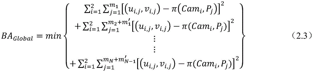
式中,m′k-1表示第k段双目视觉测量系统中相机观测到与第k-1段双目视觉测量系统中重复的物方三维点集。In the formula, m′ k-1 represents the object-space three-dimensional point set repeated by the camera in the binocular vision measurement system of the k-th segment and that in the binocular vision measurement system of the k-1st segment.
2.2深度距离和平差残差约束的自适应变权策略2.2 Adaptive weighting strategy for depth distance and difference residual constraints
所提出的自适应变权最小二乘平差策略是基于迭代重加权与深度变化加权的思想,利用深度距离和平差残差约束进行自适应定权。引入迭代重加权最小二乘法的基本思想是在光束法平差优化迭代求解中不断调整某次观测值的权值,从而减小异常点对最终全局解算结果的影响。本专利基于Huber鲁棒损失函数,在每次迭代优化前对某一观测值进行如下的迭代重加权操作:The proposed adaptive variable weight least squares adjustment strategy is based on the idea of iterative reweighting and depth change weighting, and uses depth distance and adjustment residual constraints to perform adaptive weighting. The basic idea of introducing the iterative reweighted least squares method is to continuously adjust the weight of a certain observation value in the iterative solution of bundle adjustment optimization optimization, so as to reduce the influence of abnormal points on the final global solution result. This patent is based on the Huber robust loss function, and performs the following iterative reweighting operation on a certain observation value before each iteration optimization:

式中,wr(k)表示第k次观测值迭代重加的鲁棒权重,rk表示第k次观测值经误差方程计算得到的反投影误差的二范数,即rk=‖ek‖2,δ表示异常点阈值(本专利选择常用的经验值0.001)。In the formula, w r(k) represents the robust weight iteratively added to the k-th observation value, and r k represents the bi-norm of the back-projection error calculated by the error equation of the k-th observation value, that is, r k =∥e k ‖ 2 , δ represents the outlier threshold (the commonly used experience value of 0.001 is chosen in this patent).
此外,基线B和相机焦距f即为恒定值,假设视差偏差为Δd,考虑深度Z本身(即深度范围)的大小对测量精度的影响,可推导得到:In addition, the baseline B and the camera focal length f are constant values. Assuming that the parallax deviation is Δd, considering the influence of the depth Z itself (that is, the depth range) on the measurement accuracy, it can be deduced that:

由公式2.5易知目标离镜头的距离不同,其测量的精度是不一样的。在观测视场的深度方向上,位于深度越深的同名点,其在立体像对中的视差则约小,即位于较深深度的观测点在立体像对上的像素坐标稍有微小变化,便会造成其在深度方向上较大的偏移。From the formula 2.5, it is easy to know that the distance between the target and the lens is different, and the measurement accuracy is not the same. In the depth direction of the observation field of view, the deeper the point with the same name, the smaller the parallax in the stereo pair, that is, the pixel coordinates of the observation point at a deeper depth on the stereo pair slightly change, It will cause a large deviation in the depth direction.
基于上述相关的观测经验与理论研究基础,本专利提出在平差过程中引入深度变化加权策略,对不同深度的观测值依照其与双目视觉系统基线间深度距离的倒数作为定权依据,以充分考虑由于目标点深度值较大导致观测精度降低的客观事实,避免其在较大程度上影响联合光束法平差迭代优化的过程,从而使得整体平差结果更加准确而稳定。Based on the above-mentioned relevant observation experience and theoretical research basis, this patent proposes to introduce a depth change weighting strategy in the adjustment process, and the reciprocal of the depth distance between the observation values at different depths and the baseline of the binocular vision system is used as the weighting basis. Fully consider the objective fact that the observation accuracy is reduced due to the large depth value of the target point, and avoid it from greatly affecting the iterative optimization process of the combined beam adjustment, so that the overall adjustment results are more accurate and stable.
鉴于具体观测任务时大部分观测的深度均在较高精度观测范围内,仅有远处部分观测点可能会存在上述误差,本专利采用如下的定权方式:In view of the fact that most of the observed depths are within the relatively high-precision observation range during specific observation tasks, and only some distant observation points may have the above-mentioned errors, this patent adopts the following weighting method:

式中,wz(k)表示第k次观测值的深度变化权重,Dk表示第k次观测值与双目视觉系统基线间的深度距离,Dδ表示深度距离阈值,上式表明仅对特定深度范围之外的观测进行权重修正。根据测量经验,双目视觉测量系统在两台相机光轴空间交点处具有普遍最佳的测量精度,因此本专利将Dδ设定为两台相机光轴空间交点处至双目视觉系统基线间的深度距离,该距离能够较容易地通过两台相机的初始参数交会计算得到。In the formula, w z(k) represents the depth change weight of the k-th observation value, D k represents the depth distance between the k-th observation value and the baseline of the binocular vision system, and D δ represents the depth distance threshold. The above formula shows that only for Observations outside a specified depth range are weighted. According to measurement experience, the binocular vision measurement system has generally the best measurement accuracy at the intersection of the optical axes of the two cameras, so this patent sets D δ as the distance between the intersection of the optical axes of the two cameras and the baseline of the binocular vision system The depth distance of , which can be easily calculated by the intersection of the initial parameters of the two cameras.
综上所述,所提出的自适应变权最小二乘平差策略结合每次迭代平差过程中更新的鲁棒权重,以及由所有观测点的空间三维坐标确定的深度变化权重两种权重,共同作用于上述联合光束法平差过程。In summary, the proposed adaptive variable weight least squares adjustment strategy combines the robust weights updated during each iterative adjustment process, and the depth change weight determined by the spatial three-dimensional coordinates of all observation points. Work together on the above joint bundle adjustment process.
2.3基于平面拟合的位置姿态参数动态反演2.3 Dynamic inversion of position and attitude parameters based on plane fitting
一般情况下目标模型可近似为理想刚体,模型在运动过程中不同时刻的动态姿态可等效为其与在参考初始状态下姿态之间的刚体旋转与平移变化关系,即模型表面所构成的本体坐标系在每一时刻相对于参考初始状态下的旋转与平移参数为代求量。真实场景下的模型表面较为平整,可通过粘贴于其表面的四个人工标志点所拟合的平面等效代替整个模型表面,因此模型每一时刻相对于参考初始状态的平移和旋转姿态角参数即可通过人工标志拟合平面之间的旋转和平移关系所代替,即将模型动态参数求解问题转化为基于人工标志所拟合平面的位置姿态参数动态反演问题,其原理示意图如图2所示。In general, the target model can be approximated as an ideal rigid body, and the dynamic posture of the model at different moments during the motion process can be equivalent to the rigid body rotation and translation relationship between the posture and the reference initial state, that is, the body composed of the model surface The rotation and translation parameters of the coordinate system relative to the reference initial state at each moment are substitute quantities. The surface of the model in the real scene is relatively flat, and the plane fitted by the four artificial marker points pasted on the surface is equivalent to replace the entire model surface, so the translation and rotation attitude angle parameters of the model relative to the reference initial state at each moment It can be replaced by the rotation and translation relationship between the planes fitted by artificial signs, that is, the problem of solving the dynamic parameters of the model is transformed into the dynamic inversion of the position and attitude parameters of the planes fitted by artificial signs. The schematic diagram of the principle is shown in Figure 2 .
以参考初始状态下给定的四个人工标志的三维坐标为基准,拟合平面每一时刻相对于初始状态的旋转与平移变化关系可由四个标志点间的刚体变换关系表示:With reference to the three-dimensional coordinates of the four artificial markers given in the initial state, the relationship between the rotation and translation of the fitting plane at each moment relative to the initial state can be expressed by the rigid body transformation relationship between the four marker points:

式中,Rk和tk分别为k时刻模型表面相对于参考初始状态的平移和旋转参数,总共有6个未知参数,可基于最小二乘拟合原理,使用由高速视频测量得到每一时刻4个人工标志点对应的三维坐标关系求解出Rk和tk,然后将Rk按照“ZYX”旋转轴顺序计算恢复出相对应的翻滚角roll、俯仰角yaw以及偏航角pitch。In the formula, R k and t k are the translation and rotation parameters of the model surface relative to the reference initial state at time k, respectively. There are 6 unknown parameters in total. Based on the least squares fitting principle, each moment can be obtained by high-speed video measurement The three-dimensional coordinate relationship corresponding to the four artificial marker points is solved to obtain R k and t k , and then R k is calculated according to the order of the "ZYX" rotation axis to recover the corresponding roll angle roll, pitch angle yaw, and yaw angle pitch.
3、实验与实验结果3. Experiment and experimental results
3.1多双目视觉测量系统布设3.1 Layout of multi-binocular vision measurement system
以卫星交会对接地面测试高速视频位姿测量为具体实验场景,卫星交会对接模型将沿着地面试验场导轨前向滑行约45m,为满足长距离全程测量的需求,本测量实验在导轨两侧每隔15m处共布设3对双目视觉测量系统对整个实验工况进行记录,每个单独双目视觉测量系统中两台相机间的基线长度经计算被设置为大约6.75m,其中每台相机的光轴与基线间的夹角均被设置为大约67°,以保证每个单独双目视觉测量系统均能够清晰地观测记录前方有效视场中大约15m景深范围内物体的运动变化情况,具体测量系统布设情况如图3所示。Taking the satellite rendezvous and docking ground surface test high-speed video pose measurement as the specific experimental scene, the satellite rendezvous and docking model will slide forward about 45m along the guide rail of the ground test site. A total of 3 pairs of binocular vision measurement systems were deployed at intervals of 15m to record the entire experimental conditions. The baseline length between the two cameras in each individual binocular vision measurement system was calculated to be about 6.75m, and the length of each camera The angle between the optical axis and the baseline is set to about 67° to ensure that each individual binocular vision measurement system can clearly observe and record the movement changes of objects within a depth of field of about 15m in the effective field of view ahead. The specific measurement The layout of the system is shown in Figure 3.
为了提供多双目视觉测量系统中相机外方姿态解算的坐标系基准,需要在观测视场范围内布设稳定的三维空间控制场,具体布设情况如图4所示。所有控制点的真实三维空间坐标均在实验前通过全站仪进行观测获取(精度为亚毫米级)。In order to provide the coordinate system benchmark for the calculation of the camera's external attitude in the multi-binocular vision measurement system, a stable three-dimensional space control field needs to be deployed within the observation field of view. The specific layout is shown in Figure 4. The real three-dimensional space coordinates of all control points are obtained by observation with a total station before the experiment (accuracy is submillimeter level).
3.2高速视频测量系统精度分析3.2 Accuracy analysis of high-speed video measurement system
为验证本专利所提出高速视频测量位姿估计方法的测量定位精度,可将三维控制场中的控制点分为两部分,即一部分作为稳定控制点参与联合光束法平差计算,而另一部分作为检核点参与精度评定。此外,为了验证本专利所提的自适应变权最小二乘策略的多双目视觉测量系统联合光束法平差方法的有效性,本专利还与国际著名视觉测量软件Photomodeler的分段解算方法进行了对比,具体结果如表1所示。In order to verify the measurement and positioning accuracy of the high-speed video measurement pose estimation method proposed in this patent, the control points in the three-dimensional control field can be divided into two parts, that is, one part is used as a stable control point to participate in the joint beam adjustment calculation, and the other part is used as Checkpoints participate in the accuracy assessment. In addition, in order to verify the effectiveness of the multi-binocular vision measurement system combined beam adjustment method proposed in this patent with the adaptive variable weight least squares strategy, this patent also cooperates with the segmental solution method of the internationally renowned visual measurement software Photomodeler The comparison was carried out, and the specific results are shown in Table 1.
表1Table 1

从控制场中检核点的测量精度对比情况可以看出,基于本专利所提出的联合光束法平差策略解算得到的测量精度在各方向上的均方根误差均小于2mm,总定位精度约为3mm,在15m左右的相机视场范围下相当于0.2mm/m,与国际著名视觉测量软件Photomodeler分段解算方法相比,定位精度在X、Y、Z三个方向分别提高了34.72%、36.53%和19.88%,总定位精度提升了31%,证明了本专利所提出的自适应变权联合光束法平差位姿估计方法的有效性,同时也验证高速视频测量能够满足卫星交会对接地面测试长距离位姿测量的精度要求。From the comparison of the measurement accuracy of the check points in the control field, it can be seen that the root mean square error of the measurement accuracy obtained based on the combined beam adjustment strategy proposed in this patent is less than 2mm in all directions, and the total positioning accuracy It is about 3mm, which is equivalent to 0.2mm/m at a camera field of view of about 15m. Compared with the segmental calculation method of the internationally renowned visual measurement software Photomodeler, the positioning accuracy has increased by 34.72% in the X, Y, and Z directions. %, 36.53% and 19.88%, the total positioning accuracy has increased by 31%, which proves the effectiveness of the adaptive variable weight joint beam adjustment pose estimation method proposed in this patent, and also verifies that high-speed video measurement can meet satellite rendezvous Accuracy requirements for long-distance pose measurement for ground surface testing.
3.3模型位姿参数解算结果分析3.3 Analysis of model pose parameter calculation results
使用本专利所提出的联合光束法平差策略恢复得到的相机参数,可以准确计算出模型表面四个跟踪点在空间中每一时刻的三维坐标,再使用基于平面拟合的位置姿态参数动态反演技术得到动态参数解算结果。本专利列举了几种不同运动状态下的卫星交会对接模型的位姿参数解算结果,如图5至7所示分别为模型“上仰20°”、“右偏20°”以及“左右章动”3种运动状态。Using the camera parameters restored by the combined beam adjustment strategy proposed in this patent, the three-dimensional coordinates of the four tracking points on the model surface at each moment in space can be accurately calculated, and then the dynamic reflection of position and attitude parameters based on plane fitting can be used The result of dynamic parameter calculation is obtained by performing technique. This patent lists the calculation results of the pose parameters of several satellite rendezvous and docking models in different motion states. "Moving" 3 kinds of motion states.
从上述高速视频测量动态参数解算结果可以看出,基于平面拟合的位置姿态参数动态反演能够较为准确地表现模型实际的运动状态,姿态角的变化幅度与设定的20°变化幅值保持一致且呈稳定的周期性变化,整体的位置姿态反演结果均表现得较为平滑。From the above high-speed video measurement dynamic parameter calculation results, it can be seen that the dynamic inversion of position and attitude parameters based on plane fitting can more accurately represent the actual motion state of the model, and the change range of the attitude angle is the same as the set 20° change range. Maintain a consistent and stable periodic change, and the overall position and attitude inversion results are relatively smooth.
以上所述,仅为本发明的具体实施方式,但本发明的保护范围并不局限于此,任何熟悉本技术领域的技术人员在本发明揭露的技术范围内,可轻易想到各种等效的修改或替换,这些修改或替换都应涵盖在本发明的保护范围之内。因此,本发明的保护范围应以权利要求的保护范围为准。The above is only a specific embodiment of the present invention, but the protection scope of the present invention is not limited thereto. Any person familiar with the technical field can easily think of various equivalents within the technical scope disclosed in the present invention. Modifications or replacements shall all fall within the protection scope of the present invention. Therefore, the protection scope of the present invention should be based on the protection scope of the claims.
Claims (10)


Priority Applications (1)
| Application Number | Priority Date | Filing Date | Title |
|---|---|---|---|
| CN202210799215.9A CN115311358A (en) | 2022-07-06 | 2022-07-06 | Long-distance continuous pose high-speed video measurement method |
Applications Claiming Priority (1)
| Application Number | Priority Date | Filing Date | Title |
|---|---|---|---|
| CN202210799215.9A CN115311358A (en) | 2022-07-06 | 2022-07-06 | Long-distance continuous pose high-speed video measurement method |
Publications (1)
| Publication Number | Publication Date |
|---|---|
| CN115311358A true CN115311358A (en) | 2022-11-08 |
Family
ID=83856700
Family Applications (1)
| Application Number | Title | Priority Date | Filing Date |
|---|---|---|---|
| CN202210799215.9A Pending CN115311358A (en) | 2022-07-06 | 2022-07-06 | Long-distance continuous pose high-speed video measurement method |
Country Status (1)
| Country | Link |
|---|---|
| CN (1) | CN115311358A (en) |
Cited By (1)
| Publication number | Priority date | Publication date | Assignee | Title |
|---|---|---|---|---|
| CN115877469A (en) * | 2022-11-28 | 2023-03-31 | 中煤科工西安研究院(集团)有限公司 | Low-density electrical reconstruction data volume mixed weight constraint inversion imaging method |
Citations (4)
| Publication number | Priority date | Publication date | Assignee | Title |
|---|---|---|---|---|
| WO2012040644A1 (en) * | 2010-09-24 | 2012-03-29 | Evolution Robotics, Inc. | Systems and methods for vslam optimization |
| US20160012588A1 (en) * | 2014-07-14 | 2016-01-14 | Mitsubishi Electric Research Laboratories, Inc. | Method for Calibrating Cameras with Non-Overlapping Views |
| GB201612767D0 (en) * | 2016-07-22 | 2016-09-07 | Imp College Of Science Tech And Medicine | Estimating dimensions for an enclosed space using a multi-directional camera |
| CN110766716A (en) * | 2019-09-10 | 2020-02-07 | 中国科学院深圳先进技术研究院 | Information acquisition method and system for unknown moving target in space |
-
2022
- 2022-07-06 CN CN202210799215.9A patent/CN115311358A/en active Pending
Patent Citations (4)
| Publication number | Priority date | Publication date | Assignee | Title |
|---|---|---|---|---|
| WO2012040644A1 (en) * | 2010-09-24 | 2012-03-29 | Evolution Robotics, Inc. | Systems and methods for vslam optimization |
| US20160012588A1 (en) * | 2014-07-14 | 2016-01-14 | Mitsubishi Electric Research Laboratories, Inc. | Method for Calibrating Cameras with Non-Overlapping Views |
| GB201612767D0 (en) * | 2016-07-22 | 2016-09-07 | Imp College Of Science Tech And Medicine | Estimating dimensions for an enclosed space using a multi-directional camera |
| CN110766716A (en) * | 2019-09-10 | 2020-02-07 | 中国科学院深圳先进技术研究院 | Information acquisition method and system for unknown moving target in space |
Non-Patent Citations (1)
| Title |
|---|
| XIAOHUA TONG ET AL.: "Dynamic measurement of long-distance moving object using multi-binocular high-speed videogrammetry with adaptive-weighting bundle adjustment", PHOTOGRAMMETRIC RECORD, 29 March 2024 (2024-03-29) * |
Cited By (1)
| Publication number | Priority date | Publication date | Assignee | Title |
|---|---|---|---|---|
| CN115877469A (en) * | 2022-11-28 | 2023-03-31 | 中煤科工西安研究院(集团)有限公司 | Low-density electrical reconstruction data volume mixed weight constraint inversion imaging method |
Similar Documents
| Publication | Publication Date | Title |
|---|---|---|
| CN110296691B (en) | IMU calibration-fused binocular stereo vision measurement method and system | |
| CN108489496B (en) | Non-cooperative target relative navigation motion estimation method and system based on multi-source information fusion | |
| CN110849331B (en) | Monocular vision measurement and ground test method based on three-dimensional point cloud database model | |
| CN106570905B (en) | A kind of noncooperative target point cloud initial attitude verification method | |
| CN102607526A (en) | Target posture measuring method based on binocular vision under double mediums | |
| CN109269512B (en) | A Relative Navigation Method Fusion of Planetary Landing Imagery and Ranging | |
| CN111915685B (en) | A zoom camera calibration method | |
| CN115388890B (en) | Vision-based multi-UAV cooperative ground target positioning method | |
| CN107014399A (en) | A kind of spaceborne optical camera laser range finder combined system joint calibration method | |
| CN103871075B (en) | A kind of large oval remote sensing satellite earth background relative motion method of estimation | |
| CN117197241B (en) | A high-precision tracking method for absolute posture of robot end based on multi-eye vision | |
| CN113706619B (en) | A non-cooperative target pose estimation method based on spatial mapping learning | |
| CN101539397A (en) | Method for measuring three-dimensional attitude of object on precision-optical basis | |
| CN104422425A (en) | Irregular-outline object space attitude dynamic measuring method | |
| CN114413789A (en) | Pipeline inner wall three-dimensional vision measurement data splicing device and method | |
| CN102096918B (en) | Calibration method of parameters of camera for rendezvous and docking | |
| CN116823964A (en) | Physical parameter model and calibration method of camera-galvanometer variable line of sight system | |
| CN114581515B (en) | Multi-camera calibration parameter optimization method based on optimal path conversion | |
| CN108180829B (en) | Method for measuring target space orientation with parallel line characteristics | |
| CN115311358A (en) | Long-distance continuous pose high-speed video measurement method | |
| CN114114311B (en) | A relative pose measurement method for non-cooperative spacecraft based on multi-source information fusion | |
| CN114648586B (en) | A method and storage medium for estimating vehicle absolute posture based on visual line features | |
| CN120206506A (en) | An autonomous calibration method and system for underwater manipulator based on binocular camera | |
| CN114322838A (en) | A small coincident field of view multi-eye phase deflection measurement device and method | |
| CN114663520A (en) | Double-camera combined calibration method and system for ultra-large range vision measurement |
Legal Events
| Date | Code | Title | Description |
|---|---|---|---|
| PB01 | Publication | ||
| PB01 | Publication | ||
| SE01 | Entry into force of request for substantive examination | ||
| SE01 | Entry into force of request for substantive examination |