CN115300126A - Tibial laser sight, system and method of use - Google Patents
Tibial laser sight, system and method of use Download PDFInfo
- Publication number
- CN115300126A CN115300126A CN202210932786.5A CN202210932786A CN115300126A CN 115300126 A CN115300126 A CN 115300126A CN 202210932786 A CN202210932786 A CN 202210932786A CN 115300126 A CN115300126 A CN 115300126A
- Authority
- CN
- China
- Prior art keywords
- laser
- tibial
- line
- strut
- button
- Prior art date
- Legal status (The legal status is an assumption and is not a legal conclusion. Google has not performed a legal analysis and makes no representation as to the accuracy of the status listed.)
- Pending
Links
Images


Classifications
-
- A—HUMAN NECESSITIES
- A61—MEDICAL OR VETERINARY SCIENCE; HYGIENE
- A61B—DIAGNOSIS; SURGERY; IDENTIFICATION
- A61B90/00—Instruments, implements or accessories specially adapted for surgery or diagnosis and not covered by any of the groups A61B1/00 - A61B50/00, e.g. for luxation treatment or for protecting wound edges
- A61B90/10—Instruments, implements or accessories specially adapted for surgery or diagnosis and not covered by any of the groups A61B1/00 - A61B50/00, e.g. for luxation treatment or for protecting wound edges for stereotaxic surgery, e.g. frame-based stereotaxis
- A61B90/11—Instruments, implements or accessories specially adapted for surgery or diagnosis and not covered by any of the groups A61B1/00 - A61B50/00, e.g. for luxation treatment or for protecting wound edges for stereotaxic surgery, e.g. frame-based stereotaxis with guides for needles or instruments, e.g. arcuate slides or ball joints
- A61B90/13—Instruments, implements or accessories specially adapted for surgery or diagnosis and not covered by any of the groups A61B1/00 - A61B50/00, e.g. for luxation treatment or for protecting wound edges for stereotaxic surgery, e.g. frame-based stereotaxis with guides for needles or instruments, e.g. arcuate slides or ball joints guided by light, e.g. laser pointers
-
- A—HUMAN NECESSITIES
- A61—MEDICAL OR VETERINARY SCIENCE; HYGIENE
- A61B—DIAGNOSIS; SURGERY; IDENTIFICATION
- A61B17/00—Surgical instruments, devices or methods
- A61B17/16—Instruments for performing osteoclasis; Drills or chisels for bones; Trepans
- A61B17/17—Guides or aligning means for drills, mills, pins or wires
- A61B17/1732—Guides or aligning means for drills, mills, pins or wires for bone breaking devices
-
- A—HUMAN NECESSITIES
- A61—MEDICAL OR VETERINARY SCIENCE; HYGIENE
- A61B—DIAGNOSIS; SURGERY; IDENTIFICATION
- A61B17/00—Surgical instruments, devices or methods
- A61B17/16—Instruments for performing osteoclasis; Drills or chisels for bones; Trepans
- A61B17/17—Guides or aligning means for drills, mills, pins or wires
- A61B17/1739—Guides or aligning means for drills, mills, pins or wires specially adapted for particular parts of the body
- A61B17/1764—Guides or aligning means for drills, mills, pins or wires specially adapted for particular parts of the body for the knee
- A61B17/1767—Guides or aligning means for drills, mills, pins or wires specially adapted for particular parts of the body for the knee for the patella
Landscapes
- Health & Medical Sciences (AREA)
- Surgery (AREA)
- Life Sciences & Earth Sciences (AREA)
- Medical Informatics (AREA)
- Animal Behavior & Ethology (AREA)
- Oral & Maxillofacial Surgery (AREA)
- Veterinary Medicine (AREA)
- Engineering & Computer Science (AREA)
- Biomedical Technology (AREA)
- Heart & Thoracic Surgery (AREA)
- Orthopedic Medicine & Surgery (AREA)
- Molecular Biology (AREA)
- Nuclear Medicine, Radiotherapy & Molecular Imaging (AREA)
- General Health & Medical Sciences (AREA)
- Public Health (AREA)
- Dentistry (AREA)
- Physics & Mathematics (AREA)
- Optics & Photonics (AREA)
- Pathology (AREA)
- Surgical Instruments (AREA)
Abstract
本发明公开了一种胫骨激光瞄准器、系统及使用方法,属于医疗器械技术领域,所述胫骨激光瞄准器包括用于固设在髓外定位器竖向支架上的横向支杆,横向支杆包括前支杆和与前支杆相垂直的侧支杆,前支杆上设有力线激光器,力线激光器能够投射出垂直于前支杆以用于指示胫骨力线的线激光,侧支杆上滑动连接有可摆转的后倾激光器,后倾激光器能够投射出用于指示胫骨后倾角度的线激光。本发明的胫骨激光瞄准器、系统及使用方法方便医生进行解剖标志点的寻找,并且不破坏胫骨髓腔,定位精确,操作简便。
The invention discloses a tibial laser sight, a system and a using method, belonging to the technical field of medical equipment. Including the front strut and the side strut perpendicular to the anterior strut, the force line laser is arranged on the anterior strut, and the force line laser can project a line laser perpendicular to the anterior strut to indicate the tibial force line, and the side strut The upper sliding connection is provided with a swingable retrograde laser, which can project a line laser for indicating the retrograde angle of the tibia. The tibial laser sight, the system and the using method of the present invention are convenient for doctors to search for anatomical landmarks, do not damage the tibial medullary cavity, have accurate positioning and simple operation.
Description
技术领域technical field
本发明涉及医疗器械技术领域,特别是指一种胫骨激光瞄准器、系统及使用方法。The invention relates to the technical field of medical devices, in particular to a tibial laser aiming device, system and usage method.
背景技术Background technique
膝关节是下肢重要的负重关节,其结构和功能是人体关节中最复杂者。膝关节退行性骨关节病是老年人的常见疾病,严重的膝关节骨关节病需要进行人工膝关节置换术。膝关节置换术可解除膝关节疼痛,改善膝关节功能,纠正膝关节畸形和获得长期稳定等。The knee joint is an important load-bearing joint of the lower limbs, and its structure and function are the most complex among human joints. Degenerative knee osteoarthropathy is a common disease in the elderly, and severe knee osteoarthrosis requires artificial knee replacement. Knee replacement can relieve knee pain, improve knee function, correct knee deformity and achieve long-term stability.
膝关节胫骨近端截骨是膝关节置换中最重要的一步,整个膝关节胫骨处理都是基于该步处理后的截骨平面。膝关节胫骨近端截骨的器械为近端截骨定位器,该器械分为髓内定位和髓外定位两种,该器械主要作用是完成膝关节胫骨力线的对齐/确认以及胫骨后倾角度的设定。Proximal knee tibial osteotomy is the most important step in knee arthroplasty, and the entire knee tibial treatment is based on the osteotomy plane after this step. The instrument for the proximal tibial osteotomy of the knee joint is the proximal osteotomy locator, which is divided into two types: intramedullary positioning and extramedullary positioning. Angle setting.
髓内定位是通过力线杆插入胫骨髓腔以实现定位,其优点是定位准确,缺点是会对胫骨髓腔进行破坏。髓外定位是通过外接支架完成定位,是现在的主流操作,其优点是不破坏胫骨髓腔,缺点是定位精确度欠佳,且较繁琐,需要有经验的医生操作。Intramedullary positioning is achieved by inserting a force rod into the tibial medullary cavity. The advantage is accurate positioning, but the disadvantage is that it will damage the tibial medullary cavity. Extramedullary positioning is performed by external brackets, which is the mainstream operation at present. Its advantage is that it does not damage the tibial medullary cavity. The disadvantage is that the positioning accuracy is not good, and it is cumbersome, and requires experienced doctors to operate.
发明内容Contents of the invention
本发明要解决的技术问题是提供一种不破坏胫骨髓腔,定位精确,操作简便的胫骨激光瞄准器、系统及使用方法。The technical problem to be solved by the present invention is to provide a tibial laser aiming device, a system and a use method that do not damage the tibial medullary cavity, are accurate in positioning, and are easy to operate.
为解决上述技术问题,本发明提供技术方案如下:In order to solve the problems of the technologies described above, the present invention provides technical solutions as follows:
一方面,提供一种胫骨激光瞄准器,包括用于固设在髓外定位器竖向支架上的横向支杆,所述横向支杆包括前支杆和与所述前支杆相垂直的侧支杆,所述前支杆上设有力线激光器,所述力线激光器能够投射出垂直于所述前支杆以用于指示胫骨力线的线激光,所述侧支杆上滑动连接有可摆转的后倾激光器,所述后倾激光器能够投射出用于指示胫骨后倾角度的线激光。In one aspect, a tibial laser aiming device is provided, which includes a transverse strut for being fixed on the vertical support of the extramedullary positioner, and the transverse strut includes a front strut and a side perpendicular to the front strut. A strut, the front strut is provided with a force line laser, and the force line laser can project a line laser perpendicular to the front strut for indicating the tibial force line, and the side strut is slidably connected with a An oscillating retroversion laser capable of projecting a line laser indicating tibial retroversion angle.
进一步的,所述力线激光器包括第一壳体,所述第一壳体的端面上设有用于投射线激光的第一激光器元件;Further, the line-of-force laser includes a first housing, and a first laser element for projecting a line laser is arranged on an end surface of the first housing;
和/或,所述前支杆的末端设有后向延伸板,所述力线激光器固定在所述后向延伸板上。And/or, the end of the front strut is provided with a rearward extension plate, and the force line laser is fixed on the rearward extension plate.
进一步的,所述后倾激光器包括滑动连接在所述侧支杆上的基座、以及摆动装配在所述基座上的第二壳体,所述第二壳体的端面上设有用于投射线激光的第二激光器元件,所述后倾激光器还包括用于将所述基座锁紧在所述侧支杆上的第一锁紧装置、以及用于摆动调节所述第二壳体后将所述第二壳体锁定在所述基座上的调节锁定装置。Further, the backward tilting laser includes a base that is slidably connected to the side support rod, and a second housing that is swingably mounted on the base, and the end surface of the second housing is provided with a The second laser element of the line laser, the backward tilting laser also includes a first locking device for locking the base on the side support rod, and a rear locking device for swinging and adjusting the second housing. and an adjustment lock locking the second housing to the base.
进一步的,所述第二壳体与所述基座相对的端面上设有铰接柱,所述基座上设有与所述铰接柱相配合的铰接孔,所述第二激光器元件位于所述铰接柱的端面上。Further, a hinge column is provided on the end surface of the second housing opposite to the base, and a hinge hole matching the hinge column is provided on the base, and the second laser element is located on the End faces of hinged columns.
进一步的,所述第二壳体与所述基座相对的端面下端设有竖向延伸的按钮安装槽,所述调节锁定装置为滑动连接在所述按钮安装槽内的按钮,所述按钮与所述基座相对的端面上设有定位凸起,所述基座上设有用于容纳所述定位凸起的弧形定位槽,所述弧形定位槽的内侧壁上设有与所述定位凸起相配合的齿状盘。Further, the lower end of the end surface of the second housing opposite to the base is provided with a vertically extending button installation groove, and the adjustment and locking device is a button slidingly connected in the button installation groove, and the button and The opposite end surface of the base is provided with a positioning protrusion, the base is provided with an arc-shaped positioning groove for accommodating the positioning protrusion, and the inner side wall of the arc-shaped positioning groove is provided with a Raised mating toothed discs.
进一步的,所述按钮包括按钮主体,所述按钮主体上设有凸型导轨,所述凸型导轨上设有所述定位凸起;所述按钮安装槽为与所述凸型导轨相配合的凸型导轨槽;Further, the button includes a button main body, and a convex guide rail is provided on the button main body, and the positioning protrusion is provided on the convex guide rail; the button installation groove is matched with the convex guide rail Convex rail groove;
和/或,所述定位凸起的下端为尖状,所述弧形定位槽的下侧壁上设有所述齿状盘;And/or, the lower end of the positioning protrusion is pointed, and the toothed disc is provided on the lower side wall of the arc-shaped positioning groove;
和/或,所述按钮安装槽内设有用于使所述按钮保持在锁定位置的弹簧。And/or, a spring for keeping the button at the locked position is provided in the button installation groove.
另一方面,提供一种胫骨激光瞄准系统,包括髓外定位器,所述髓外定位器从下至上依次包括抱踝器、竖向支架和横向定位板,所述竖向支架上设有上述的胫骨激光瞄准器。On the other hand, a tibial laser aiming system is provided, which includes an extramedullary locator, and the extramedullary locator sequentially includes an ankle gripper, a vertical bracket and a lateral positioning plate from bottom to top, and the vertical bracket is provided with the above-mentioned tibia laser sight.
进一步的,所述竖向支架上固设有支杆连接件,所述支杆连接件设有接口母头,所述前支杆上设有与所述接口母头相配合的接头公头、以及用于将所述接头公头锁紧在所述接口母头内的第二锁紧装置。Further, the vertical bracket is fixed with a pole connecting piece, the pole connecting piece is provided with a female interface, and the front pole is provided with a male joint, which matches the female interface, And a second locking device for locking the connector male head in the interface female head.
再一方面,提供上述的胫骨激光瞄准系统的使用方法,所述方法包括:In another aspect, a method for using the above-mentioned tibial laser aiming system is provided, the method comprising:
步骤1:调节所述力线激光器,使所述力线激光器投射出的线激光与所述髓外定位器的竖向支架的轴线重合;Step 1: Adjust the line of force laser so that the line laser projected by the line of force laser coincides with the axis of the vertical support of the extramedullary locator;
步骤2:调节所述后倾激光器,使所述后倾激光器投射出的线激光与胫骨前缘平行;Step 2: adjusting the retroverted laser so that the line laser projected by the retroverted laser is parallel to the front edge of the tibia;
步骤3:调节所述后倾激光器的后倾角度至预设角度;Step 3: adjusting the backward tilt angle of the backward tilt laser to a preset angle;
步骤4:锁定所述后倾激光器,并调节所述竖向支架,使所述后倾激光器投射出的线激光与胫骨前缘平行。Step 4: Lock the retroverted laser, and adjust the vertical support so that the line laser projected by the retroverted laser is parallel to the front edge of the tibia.
进一步的,所述预设角度为术前胫骨的后倾角度。Further, the preset angle is the posterior tilt angle of the tibia before operation.
本发明具有以下有益效果:The present invention has the following beneficial effects:
本发明的胫骨激光瞄准器、系统及使用方法,其胫骨激光瞄准器的横向支杆的前支杆上设有力线激光器,力线激光器能够投射出垂直于前支杆以用于指示胫骨力线的线激光,胫骨激光瞄准器的横向支杆的侧支杆上滑动连接有可摆转的后倾激光器,后倾激光器能够投射出用于指示胫骨后倾角度的线激光,相比于现有技术,本发明采用两个激光器投射两束线激光至人体胫骨位置,以分别指示胫骨力线和胫骨后倾角度,方便医生进行解剖标志点的寻找,并且不破坏胫骨髓腔,定位精确,操作简便。In the tibial laser sight, system and method of use of the present invention, the front strut of the transverse strut of the tibial laser sight is provided with a force line laser, and the force line laser can project a line of force perpendicular to the front strut for indicating the tibial force line. The line laser of the tibial laser aimer is slidably connected to the side strut of the lateral strut of the tibial laser aiming device. Technology, the present invention uses two lasers to project two beams of laser light to the tibia position of the human body to indicate the force line of the tibia and the retroversion angle of the tibia respectively, which is convenient for doctors to search for anatomical landmarks, and does not destroy the tibial medullary cavity, with accurate positioning and easy operation. easy.
附图说明Description of drawings
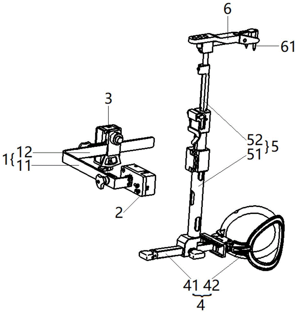
图1为本发明的胫骨激光瞄准系统的整体结构示意图;Fig. 1 is the overall structure schematic diagram of tibial laser aiming system of the present invention;
图2为本发明的胫骨激光瞄准系统中胫骨激光瞄准器的结构示意图;Fig. 2 is the structural representation of the tibial laser aiming device in the tibial laser aiming system of the present invention;
图3为本发明的胫骨激光瞄准系统中胫骨激光瞄准器的L形横向支杆的结构示意图;Fig. 3 is the structural representation of the L-shaped transverse strut of the tibial laser aiming device in the tibial laser aiming system of the present invention;
图4为本发明的胫骨激光瞄准系统中胫骨激光瞄准器的力线激光器的结构示意图;Fig. 4 is the structural representation of the line of force laser device of the tibial laser aiming device in the tibial laser aiming system of the present invention;
图5为本发明的胫骨激光瞄准系统中胫骨激光瞄准器的后倾激光器的分解结构示意图;FIG. 5 is a schematic diagram of the exploded structure of the backward tilting laser of the tibial laser aiming system in the tibial laser aiming system of the present invention;
图6为本发明的胫骨激光瞄准系统中胫骨激光瞄准器的后倾激光器的第二壳体的结构示意图,其中(a)为一个方向的立体图,(b)为另一方向的立体图;Fig. 6 is the structural representation of the second housing of the backward tilting laser of the tibial laser aiming device in the tibial laser aiming system of the present invention, wherein (a) is a perspective view in one direction, and (b) is a perspective view in another direction;
图7为本发明的胫骨激光瞄准系统中胫骨激光瞄准器的后倾激光器的基座的结构示意图;Fig. 7 is the structural representation of the base of the backward tilting laser of the tibial laser aiming device in the tibial laser aiming system of the present invention;
图8为本发明的胫骨激光瞄准系统中胫骨激光瞄准器的后倾激光器的按钮的结构示意图;Fig. 8 is a structural schematic diagram of the button of the backward tilting laser of the tibial laser aiming device in the tibial laser aiming system of the present invention;
图9为本发明的胫骨激光瞄准系统中髓外定位器的结构示意图,其中(a)为立体图,(b)为(a)中支杆连接件处的放大图;9 is a schematic structural view of the extramedullary locator in the tibial laser aiming system of the present invention, wherein (a) is a perspective view, and (b) is an enlarged view of the strut connector in (a);
图10为本发明的胫骨激光瞄准系统的一个方向的使用状态示意图;Fig. 10 is a schematic diagram of the use state of the tibial laser aiming system in one direction of the present invention;
图11为本发明的胫骨激光瞄准系统的另一方向的使用状态示意图。Fig. 11 is a schematic view of another direction of use of the tibial laser aiming system of the present invention.
具体实施方式Detailed ways
为使本发明要解决的技术问题、技术方案和优点更加清楚,下面将结合附图及具体实施例进行详细描述。In order to make the technical problems, technical solutions and advantages to be solved by the present invention clearer, the following will describe in detail with reference to the drawings and specific embodiments.
在本发明的描述中,需要理解的是,术语“上”、“下”、“前”、“后”、“左”、“右”等指示的方位或位置关系为基于附图所示的方位或位置关系,仅是为了便于描述本发明和简化描述,而不是指示或暗示所指的装置或元件必须具有特定的方位、以特定的方位构造和操作,因此不能理解为对本发明的限制。In the description of the present invention, it should be understood that the orientation or positional relationship indicated by the terms "upper", "lower", "front", "rear", "left", "right" etc. are based on those shown in the accompanying drawings. Orientation or positional relationship is only for the convenience of describing the present invention and simplifying the description, and does not indicate or imply that the referred device or element must have a specific orientation, be constructed and operated in a specific orientation, and thus should not be construed as a limitation of the present invention.
一方面,本发明提供一种胫骨激光瞄准器,如图1-11所示,包括用于固设在髓外定位器竖向支架5上的横向支杆1(具体可以为L形),横向支杆1包括前支杆11(具体的,前支杆11用于置于胫骨10前侧)和与前支杆11相垂直的侧支杆12(具体的,侧支杆12用于置于胫骨10内侧),前支杆11上设有力线激光器2,力线激光器2能够投射出垂直于前支杆11以用于指示胫骨10力线P的线激光M,侧支杆12上滑动连接有可摆转的后倾激光器3,后倾激光器3能够投射出用于指示胫骨10后倾角度的线激光N。On the one hand, the present invention provides a tibial laser aiming device, as shown in Fig. 1-11, comprising a transverse strut 1 (specifically L-shaped) for being fixed on the
本发明的胫骨激光瞄准器,其胫骨激光瞄准器的横向支杆的前支杆上设有力线激光器,力线激光器能够投射出垂直于前支杆以用于指示胫骨力线的线激光,胫骨激光瞄准器的横向支杆的侧支杆上滑动连接有可摆转的后倾激光器,后倾激光器能够投射出用于指示胫骨后倾角度的线激光,相比于现有技术,本发明采用两个激光器投射两束线激光至人体胫骨位置,以分别指示胫骨力线和胫骨后倾角度,方便医生进行解剖标志点的寻找,并且不破坏胫骨髓腔,定位精确,操作简便。本发明主要适用于膝关节置换的胫骨髓外定位截骨手术,用于辅助膝关节胫骨力线的对位及胫骨后倾角度的设定。In the tibial laser sight of the present invention, the front strut of the transverse strut of the tibial laser sight is provided with a force line laser, and the force line laser can project a line laser perpendicular to the front strut for indicating the tibial force line. The lateral strut of the laser aiming device is slidably connected with a swingable retroverted laser, which can project a line laser for indicating the tibial retroverted angle. Compared with the prior art, the present invention adopts Two lasers project two beams of laser light to the position of the human tibia to indicate the tibial force line and tibial retroversion angle respectively, which is convenient for doctors to find anatomical landmarks without destroying the tibial medullary cavity, with accurate positioning and easy operation. The invention is mainly applicable to tibial extramedullary positioning osteotomy operation for knee joint replacement, and is used for assisting the alignment of tibial force line of knee joint and setting of tibial retroversion angle.
力线激光器2优选采用以下结构:Line of
如图4所示,力线激光器2可以包括第一壳体21,第一壳体21的端面(与胫骨10前侧相对的端面)上设有用于投射线激光M的第一激光器元件22。如图3所示,前支杆11的末端可以设有后向延伸板13,力线激光器2固定(具体的,力线激光器2的第一壳体21可以采用螺钉固定)在后向延伸板13上,以方便固设力线激光器2。As shown in FIG. 4 , the line of
为使后倾激光器3可摆转且滑动连接在侧支杆12上,本发明优选采用以下结构形式:In order to make the backward tilting
如图2和图5-8所示,后倾激光器3可以包括滑动连接在侧支杆12上的基座31、以及摆动装配在基座31上的第二壳体32,第二壳体32的端面(与胫骨10内侧相对的端面)上设有用于投射线激光N的第二激光器元件33,后倾激光器3还包括用于将基座31锁紧在侧支杆12上的第一锁紧装置34、以及用于摆动调节第二壳体32后将第二壳体32锁定在基座31上的调节锁定装置。As shown in Figure 2 and Figures 5-8, the backward tilting
使用时,待后倾激光器3与L形横向支杆1的侧支杆12组合后,驱动后倾激光器3的基座31在侧支杆12上前后滑动至合适位置,并利用第一锁紧装置34将基座31锁紧在侧支杆12上,以适应不同胖瘦的患者对应的胫骨10,同时,可利用调节锁定装置摆动调节第二壳体32与基座31的相对角度并锁定,进而调节胫骨10后倾角度,以满足术中需求。第二壳体32上可以设有角度刻度321,以方便调节胫骨10后倾角度,角度刻度321的数值可以根据术中需要灵活设定,例如可以为0度、3度、5度、7度、9度等。When in use, after the
如图5-7所示,为方便使第二壳体32摆动装配在基座31上,第二壳体32与基座31相对的端面上可以设有铰接柱322,基座31上设有与铰接柱322相配合的铰接孔311,第二激光器元件33位于铰接柱322的端面上。As shown in Figures 5-7, in order to make the
调节锁定装置用于在摆动调节第二壳体32后将第二壳体32锁定在基座31上,其优选采用以下结构形式:The adjustment locking device is used to lock the
如图5-8所示,第二壳体32与基座31相对的端面下端可以设有竖向延伸的按钮安装槽323,调节锁定装置为滑动连接在按钮安装槽323内的按钮35,按钮35与基座31相对的端面上设有定位凸起351,基座31上设有用于容纳定位凸起351的弧形定位槽312,弧形定位槽312的内侧壁上设有与定位凸起351相配合的齿状盘313。As shown in Figures 5-8, the lower end of the end face of the
使用时,驱动按钮35在按钮安装槽323内滑动,使按钮35上的定位凸起351与基座31的弧形定位槽312内侧壁上的齿状盘313分离,第二壳体32为解锁状态,此时可沿铰接柱322摆动调节第二壳体32,以调节胫骨10后倾角度;需要将第二壳体32锁定在基座31上时,驱动按钮35在按钮安装槽323内滑动,使按钮35上的定位凸起351与齿状盘313再次啮合,第二壳体32变为锁定状态,以锁定胫骨10后倾角度。During use, the
如图8所示,按钮35可以包括按钮主体352,按钮主体352上设有凸型导轨353,凸型导轨353上设有定位凸起351;按钮安装槽323为与凸型导轨353相配合的凸型导轨槽,以使按钮35稳定的在按钮安装槽323内滑动,防止按钮35从按钮安装槽323内脱出。As shown in Figure 8, the
继续如图5-8所示,定位凸起351的下端可以为尖状,弧形定位槽312的下侧壁上设有齿状盘313;按钮安装槽323内可以设有用于使按钮35保持在锁定位置的弹簧36,以快速锁定胫骨10后倾角度,方便术中使用,提高定位凸起351与齿状盘313之间的稳定性和牢固性,使第二壳体32牢固锁定在基座31上。此时,按压按钮35即可使第二壳体32变为解锁状态,松开按钮35即可使第二壳体32变为锁定状态。Continue as shown in Figure 5-8, the lower end of
另一方面,本发明提供一种胫骨激光瞄准系统,如图1-11所示,包括髓外定位器,髓外定位器从下至上依次包括抱踝器4、竖向支架5和横向定位板6,竖向支架5上设有上述的胫骨激光瞄准器。由于胫骨激光瞄准器的结构与上相同,故此处不再赘述。On the other hand, the present invention provides a tibial laser aiming system, as shown in Fig. 1-11, which includes an extramedullary locator, and the extramedullary locator includes an
本发明的胫骨激光瞄准系统,其胫骨激光瞄准器的横向支杆的前支杆上设有力线激光器,力线激光器能够投射出垂直于前支杆以用于指示胫骨力线的线激光,胫骨激光瞄准器的横向支杆的侧支杆上滑动连接有可摆转的后倾激光器,后倾激光器能够投射出用于指示胫骨后倾角度的线激光,相比于现有技术,本发明采用两个激光器投射两束线激光至人体胫骨位置,以分别指示胫骨力线和胫骨后倾角度,方便医生进行解剖标志点的寻找,并且不破坏胫骨髓腔,定位精确,操作简便。In the tibial laser aiming system of the present invention, the front strut of the transverse strut of the tibial laser aimer is provided with a force line laser, and the force line laser can project a line laser perpendicular to the front strut for indicating the tibial force line. The lateral strut of the laser aiming device is slidably connected with a swingable retroverted laser, which can project a line laser for indicating the tibial retroverted angle. Compared with the prior art, the present invention adopts Two lasers project two beams of laser light to the position of the human tibia to indicate the tibial force line and tibial retroversion angle respectively, which is convenient for doctors to find anatomical landmarks without destroying the tibial medullary cavity, with accurate positioning and easy operation.
如图1和图9所示,抱踝器4可以包括支撑杆41和连接在支撑杆41端部的抱踝夹持部42,竖向支架5的下端滑动连接(前后滑动)在支撑杆41上,竖向支架5的上端铰接横向定位板6的一端,横向定位板6的另一端下表面设有用于固定至胫骨平台20的固定钉61,使用时将固定钉61钉入胫骨平台20,为胫骨10后倾角度的调节提供支点。As shown in Figures 1 and 9, the ankle-holding
进一步的,为适应不同长度的胫骨10,竖向支架5可以包括套筒51、上下滑动连接在套筒51内的定位杆52、以及用于锁定套筒51和定位杆52相对位置的锁紧装置。该锁紧装置可以采用本领域常规技术手段,例如锁紧装置包括设置在定位杆52一侧的棘齿面、以及转动装配在套筒51上与棘齿面相配合的棘轮。Further, in order to adapt to
为方便将胫骨激光瞄准器安装在竖向支架5上,可以采用本领域技术人员容易想到的各种结构形式,例如焊接、粘接等;然而,为方便拆卸,本发明优选采用以下结构形式:For convenience, the tibial laser aimer is installed on the
如图3和图9所示,竖向支架5(套筒51)上可以固设有支杆连接件53,支杆连接件53设有接口母头54(具体的,支杆连接件53远离胫骨10的一侧设有接口母头54,接口母头54可以为方形通槽),前支杆11上设有与接口母头54相配合的接头公头14(可以为方形凸起/插板)、以及用于将接头公头14锁紧在接口母头54内的第二锁紧装置15。As shown in Figure 3 and Figure 9, a
使用时,将前支杆11上的接头公头14插入竖向支架5的支杆连接件53的接口母头54内,并利用第二锁紧装置15将接头公头14锁紧在接口母头54内,进而将胫骨激光瞄准器固设在竖向支架5上。When in use, insert the
本发明中的第一锁紧装置34和第二锁紧装置15均可以采用本领域技术人员容易想到的各种结构形式,然而,为方便实施,本发明中的第一锁紧装置34和第二锁紧装置15均可以为用于挤压固定的锁紧旋钮。The
再一方面,本发明提供上述的胫骨激光瞄准系统的使用方法,所述方法包括:In another aspect, the present invention provides a method for using the above-mentioned tibial laser aiming system, the method comprising:
步骤1:调节所述力线激光器2,使所述力线激光器2投射出的线激光M与所述髓外定位器的竖向支架5的轴线重合(参见图10);Step 1: Adjust the line of
步骤2:调节所述后倾激光器3,使所述后倾激光器3投射出的线激光N与胫骨前缘平行;Step 2: adjusting the
本步骤中,先将后倾激光器3上显示的后倾角度调整为0度(刻度归零),待后倾激光器3与L形横向支杆1的侧支杆12组合后,将后倾激光器3发出的线激光N投影到胫骨10内侧,驱动后倾激光器3的基座31在侧支杆12上前后滑动,以适应不同胖瘦的患者对应的胫骨10,使得后倾激光器3投射出的线激光N与胫骨10前缘平行(即胫骨10前缘所在直线O),利用第一锁紧装置34将基座31锁紧在侧支杆12上,完成后倾激光器0度后倾的定义;In this step, the backward tilt angle displayed on the
步骤3:调节所述后倾激光器3的后倾角度至预设角度;Step 3: adjusting the backward tilt angle of the
本步骤中,预设角度可以为术前胫骨10的后倾角度,即医生根据术前测量得出的后倾角度;使用时,按压按钮35使弹簧36压缩,按钮35上的定位凸起351与基座31的弧形定位槽312内侧壁上的齿状盘313分离,第二壳体32变为解锁状态,即可摆动调节后倾激光器3至预设角度,调节完毕后,松开按钮35,在弹簧36弹力的作用下,将定位凸起351重新压入齿状盘313的牙内,第二壳体32变为锁定状态,以锁定当前后倾激光器3的角度。In this step, the preset angle can be the retroversion angle of the
步骤4:锁定所述后倾激光器3,并调节所述竖向支架5,使所述后倾激光器3投射出的线激光N与胫骨前缘平行;Step 4: locking the backward tilting
本步骤中,由于胫骨激光瞄准系统的髓外定位器的竖向支架5的上部设有胫骨截骨器,胫骨截骨器的截骨面始终与髓外定位器的竖向支架5相垂直(即胫骨截骨器的刀槽始终与竖向支架5呈90度),向后拉动竖向支架5,即可使胫骨截骨器的截骨面向后倾斜;初始情况时,后倾激光器3投射出的线激光N与竖向支架5平行,也即与胫骨10前缘平行,当后倾激光器3投射出的线激光N调节到某个角度(例如预设角度)时,其与竖向支架5也呈某个角度,此时拉动竖向支架5,使后倾激光器3投射出的线激光N再次与胫骨10前缘平行,就是拉动了相应的某个角度,所以对应的就产生了某个角度的后倾角,定位更精确。In this step, since the top of the
以上所述是本发明的优选实施方式,应当指出,对于本技术领域的普通技术人员来说,在不脱离本发明所述原理的前提下,还可以作出若干改进和润饰,这些改进和润饰也应视为本发明的保护范围。The above description is a preferred embodiment of the present invention, it should be pointed out that for those of ordinary skill in the art, without departing from the principle of the present invention, some improvements and modifications can also be made, and these improvements and modifications can also be made. It should be regarded as the protection scope of the present invention.
Claims (10)
Priority Applications (1)
| Application Number | Priority Date | Filing Date | Title |
|---|---|---|---|
| CN202210932786.5A CN115300126A (en) | 2022-08-04 | 2022-08-04 | Tibial laser sight, system and method of use |
Applications Claiming Priority (1)
| Application Number | Priority Date | Filing Date | Title |
|---|---|---|---|
| CN202210932786.5A CN115300126A (en) | 2022-08-04 | 2022-08-04 | Tibial laser sight, system and method of use |
Publications (1)
| Publication Number | Publication Date |
|---|---|
| CN115300126A true CN115300126A (en) | 2022-11-08 |
Family
ID=83858866
Family Applications (1)
| Application Number | Title | Priority Date | Filing Date |
|---|---|---|---|
| CN202210932786.5A Pending CN115300126A (en) | 2022-08-04 | 2022-08-04 | Tibial laser sight, system and method of use |
Country Status (1)
| Country | Link |
|---|---|
| CN (1) | CN115300126A (en) |
Citations (12)
| Publication number | Priority date | Publication date | Assignee | Title |
|---|---|---|---|---|
| US20030100907A1 (en) * | 2001-11-28 | 2003-05-29 | Rosa Richard A. | Instrumentation for minimally invasive unicompartmental knee replacement |
| CN202313674U (en) * | 2011-11-18 | 2012-07-11 | 北京纳通科技集团有限公司 | Tibia osteotomy positioning system as well as ankle mortice working platform and bone cutting plate working platform thereof |
| JP2016137059A (en) * | 2015-01-27 | 2016-08-04 | 京セラメディカル株式会社 | Surgical measuring instrument |
| CN105832427A (en) * | 2016-03-18 | 2016-08-10 | 南京鼓楼医院 | In-vitro laser alignment guidance system for minimally invasive intracranial hematoma cleaning operation and positioning method |
| CN107961056A (en) * | 2017-11-24 | 2018-04-27 | 中国人民解放军总医院第附属医院 | A kind of line of force measurement angle positioner for knee joint peripheral osteotomy |
| CN109009484A (en) * | 2018-08-23 | 2018-12-18 | 秦福安 | A kind of acetabular bone laser locating apparatus and localization method |
| CN208339561U (en) * | 2017-07-26 | 2019-01-08 | 嘉思特华剑医疗器材(天津)有限公司 | Osteotomy guider is positioned outside accurate shin bone marrow |
| CN209018853U (en) * | 2018-06-28 | 2019-06-25 | 北京纳通医学科技研究院有限公司 | Tibial osteotomy plate positioner and tibial osteotomy device |
| CN110613537A (en) * | 2019-09-16 | 2019-12-27 | 北京力达康科技有限公司 | Medical orthopedics femoral stem anteversion angle calibrator |
| JP2020018382A (en) * | 2018-07-30 | 2020-02-06 | 大平 来田 | Laser projection appliance and guide appliance |
| CN111616770A (en) * | 2020-05-21 | 2020-09-04 | 天衍医疗器材有限公司 | Tibia osteotomy positioning device |
| CN114469253A (en) * | 2021-12-17 | 2022-05-13 | 中国人民解放军总医院第四医学中心 | A laser device for accurately indicating the osteotomy plane in artificial knee arthroplasty |
-
2022
- 2022-08-04 CN CN202210932786.5A patent/CN115300126A/en active Pending
Patent Citations (13)
| Publication number | Priority date | Publication date | Assignee | Title |
|---|---|---|---|---|
| US20030100907A1 (en) * | 2001-11-28 | 2003-05-29 | Rosa Richard A. | Instrumentation for minimally invasive unicompartmental knee replacement |
| CN202313674U (en) * | 2011-11-18 | 2012-07-11 | 北京纳通科技集团有限公司 | Tibia osteotomy positioning system as well as ankle mortice working platform and bone cutting plate working platform thereof |
| JP2016137059A (en) * | 2015-01-27 | 2016-08-04 | 京セラメディカル株式会社 | Surgical measuring instrument |
| US20170354425A1 (en) * | 2015-01-27 | 2017-12-14 | Kyocera Corporation | Surgical measurement instrument |
| CN105832427A (en) * | 2016-03-18 | 2016-08-10 | 南京鼓楼医院 | In-vitro laser alignment guidance system for minimally invasive intracranial hematoma cleaning operation and positioning method |
| CN208339561U (en) * | 2017-07-26 | 2019-01-08 | 嘉思特华剑医疗器材(天津)有限公司 | Osteotomy guider is positioned outside accurate shin bone marrow |
| CN107961056A (en) * | 2017-11-24 | 2018-04-27 | 中国人民解放军总医院第附属医院 | A kind of line of force measurement angle positioner for knee joint peripheral osteotomy |
| CN209018853U (en) * | 2018-06-28 | 2019-06-25 | 北京纳通医学科技研究院有限公司 | Tibial osteotomy plate positioner and tibial osteotomy device |
| JP2020018382A (en) * | 2018-07-30 | 2020-02-06 | 大平 来田 | Laser projection appliance and guide appliance |
| CN109009484A (en) * | 2018-08-23 | 2018-12-18 | 秦福安 | A kind of acetabular bone laser locating apparatus and localization method |
| CN110613537A (en) * | 2019-09-16 | 2019-12-27 | 北京力达康科技有限公司 | Medical orthopedics femoral stem anteversion angle calibrator |
| CN111616770A (en) * | 2020-05-21 | 2020-09-04 | 天衍医疗器材有限公司 | Tibia osteotomy positioning device |
| CN114469253A (en) * | 2021-12-17 | 2022-05-13 | 中国人民解放军总医院第四医学中心 | A laser device for accurately indicating the osteotomy plane in artificial knee arthroplasty |
Similar Documents
| Publication | Publication Date | Title |
|---|---|---|
| US11534186B2 (en) | Orthopedic surgical guide | |
| EP0857463B1 (en) | Tibial plateau resection guide | |
| CA2376019C (en) | Tibial plateau resection guide | |
| US5766179A (en) | Mechanical system for blind nail-hole alignment of bone screws | |
| US20050070897A1 (en) | Laser triangulation of the femoral head for total knee arthroplasty alignment instruments and surgical method | |
| CN215994136U (en) | Adjustable thighbone cuts bone apparatus | |
| KR19980702248A (en) | Distal Femoral Cut Guide | |
| US10729452B2 (en) | Tibia cutting assembly | |
| US20120136359A1 (en) | Femoral cutting guide device for revision operations in knee endoprosthetics | |
| CN103582461B (en) | Orthopedic surgical guide | |
| CN106974700A (en) | A kind of proximal tibia osteotomy instrument kit | |
| CN115300126A (en) | Tibial laser sight, system and method of use | |
| CN210811350U (en) | Alignment and positioning device for distal femoral osteotomy | |
| CN2636832Y (en) | Orthopedic osteotomy correction surgery angle positioning auxiliary device | |
| CN212438754U (en) | A kind of osteotomy locator for distal femoral condyle bone defect | |
| US12508039B2 (en) | Orthopedic surgical guide | |
| US20210236147A1 (en) | Arrangements and methods in the preparation of the proximal surface of the tibia and/or femur and posterior femoral condyle proximal surfaces for the components of a prosthetic knee joint | |
| CN116392265A (en) | Femur measuring device for knee osteotomy | |
| RU2233642C2 (en) | Articulator | |
| CN209826868U (en) | Tibia osteotomy caster angle regulator | |
| CN209695307U (en) | The brill guider of integrated angle adjustable | |
| CN116509499B (en) | A multifunctional fine-adjustable tibial medullary cavity positioning osteotomy device | |
| CN119856990B (en) | A knee joint force line measurement system | |
| CN223054550U (en) | Lamb's crest positioning device | |
| CN119523567A (en) | A new laser emission positioning osteotomy device |
Legal Events
| Date | Code | Title | Description |
|---|---|---|---|
| PB01 | Publication | ||
| PB01 | Publication | ||
| SE01 | Entry into force of request for substantive examination | ||
| SE01 | Entry into force of request for substantive examination |