Disclosure of Invention
The object of the present invention is to overcome all or some of the limitations of the prior art solutions by providing the following systems and methods: the system and method make it possible to maximize the expiratory time of the subject by means of a relaxed expiration by means of a tracheo-bronchial-air stimulation device, so that the lungs of the subject are emptied as much as possible to increase the efficiency of stimulation (i.e. apply an acceptably greater negative pressure), while taking into account the tolerance of the subject to the negative pressure (i.e. avoid coughing). The stimulation is improved by real-time control of the negative pressure.
To this end, according to a first aspect, the subject of the invention is an automatic control system for a tracheobronchial-air stimulation device intended to be connected to a subject, the stimulation device comprising a pressure unit configured to generate a set of negative pressure pulses during a relaxed exhalation of the subject, each pulse corresponding to a power of the pressure unit, and a connection assembly configured to connect the pressure unit to the respiratory system of the subject, wherein the control system comprises:
a pressure sensor configured to measure, after each pulse generated by the pressure unit, an internal negative pressure (inner negative pressure) applied to the respiratory system of the subject corresponding to said pulse,
a calculation module configured to compare in real time the absolute value of the measured internal negative pressure with a predetermined threshold value and to determine, based on the comparison result, an updated power value to be applied to the pressure unit such that the absolute value of the subsequent internal negative pressure corresponding to the updated power value is below the absolute value of the threshold value,
-a control module configured to apply the updated power value to the pressure unit before the next pulse is generated.
By "respiratory system of a subject" is meant the collection of airways of the subject, including such ducts as the pharynx, larynx and bronchi, as well as the lungs themselves.
"relaxed breath" refers to the fact that: air is drawn from the lungs of the subject by means of the pulse only, i.e. the subject does not exhale by his/her own will. Further, "power" refers to an amount representing the amount of air drawn for each negative pressure pulse. Therefore, if such power is increased/decreased, it corresponds to a case where the amount of air drawn for negative pressure is increased/decreased due to the power increase/decrease. Here, if the negative pressure increases, it means that the absolute value of the negative pressure increases; in other words, as negative pressure increases, lower pressure is applied to the subject.
The "internal negative pressure" is the pressure actually experienced by the subject, i.e., the pressure in the mouth of the subject, at the entrance of the airway. Typically, the value of the internal underpressure is-10 mbar to-100 mbar when the apparatus is in operation. The internal negative pressure may differ from the expected negative pressure pulse generated by the pressure unit at the control power value. In practice, a given power value of the pressure unit would generate a theoretical negative pressure, typically from-300 mbar for a full power value to 0 mbar at a minimum power value, but the actual negative pressure is affected by various characteristics: tubing, expiratory phase and actual subject anatomy, etc. The internal negative pressure is a relevant parameter of the automatic control system.
By "real-time" is meant that the comparison of the absolute value of the measured internal negative pressure (during the current negative pressure pulse) with the threshold value is fast enough to modify the command sent to the pressure unit for the next negative pressure pulse. For a negative pressure frequency of 12Hz, the calculation module should complete the comparison within 80 ms. For a negative pressure frequency of 6Hz, the calculation module should complete the comparison within 160 ms. The internal negative pressure can be measured at a sampling rate of 100Hz for comparison and control of pressure units.
Thus, the system is first based on real-time measurements of said internal negative pressure to generate an actual negative pressure felt by the subject, which may be different from the negative pressure applied by the pressure unit. The calculation module uses this measured internal negative pressure to compare it to a threshold value and then determines a power value to ensure that the next negative pressure pulse remains below the threshold value.
In this way, if the internal negative pressure associated with a pulse exceeds a threshold, such exceeding does not last at least until the next pulse. In other words, this prevents the internal negative pressure from being maintained above the threshold for too long, so that the relaxed exhalation is not stopped prematurely by the subject, e.g. due to his/her feeling in need of a cough. Finally, a relaxing expiration is performed for a sufficient period of time such that the subject completely empties the air contained in his/her lungs, which facilitates the expulsion of mucus during the relaxing expiration.
Furthermore, such a system may prevent the internal negative pressure from being maintained at a too low level for too long as the threshold is not exceeded. In other words, it may prevent too little air volume from being removed from the lungs of the subject, thereby improving mucus drainage efficiency during relaxed expiration.
Finally, with such an automatic control system, the negative pressure applied to the subject never exceeds an acceptable value below the threshold at which the subject will begin to cough throughout the period of relaxed expiration.
In particular embodiments, the system may additionally comprise one or more of the following features taken alone or according to any technically possible combination.
According to an embodiment, the system further comprises an acquisition module configured to acquire a value of the measured internal negative pressure associated with each pulse generated by the pressure unit during the relaxed expiration of the subject and after said pulse.
According to one embodiment, the calculation module is configured to determine whether the absolute value of the measured internal negative pressure exceeds the absolute value of the threshold value and, in the case of exceeding, to determine a reduced power value to be applied to the pressure unit. Thus, the comparison makes it possible to detect the exceeding of the threshold, which then ensures that the calculation module generates the appropriate power value to optimize the operation of the stimulation device.
According to one embodiment, the calculation module is configured to determine the reduced power value as a function of the difference between the absolute value of the measured internal negative pressure and the absolute value of the threshold value, so that the absolute value of the subsequent internal negative pressure corresponding to said reduced power value is reduced by a value of 10 mbar to 60 mbar compared to said measured internal negative pressure. The selection of such a range advantageously reduces the internal negative pressure sufficiently that the subject does not experience any breathing discomfort and therefore can continue to use the stimulation device. In other words, the subject does not feel the need to remove the tip from the mouth so that the lungs continue to be emptied, which enhances the extraction of air from the lungs. Furthermore, targeting such specific ranges allows the operation of the stimulation device to be carefully controlled.
According to one embodiment, the reduced power value is determined among a set of predetermined power values. Such a configuration makes it possible to simplify the electronic architecture of the system, since the reduced power values can be pre-programmed.
According to one embodiment, the predetermined value is substantially equal to a multiple of one tenth of the maximum power of the pressure unit. Selecting such values makes it possible to obtain good efficiency while maintaining a simplified electronic architecture.
According to one embodiment, when the calculation module determines several reduced power values during the relaxed expiration of the subject, the values form a constant sequence over time. Such a configuration ensures that the subject does not rush during relaxed expiration, as he/she is always facing the same power reduction. As a result, the subject's interaction with the stimulation device is smoother, which improves comfort and efficiency of production.
According to one embodiment, the calculation module is configured to determine whether the absolute value of the measured internal negative pressure exceeds the absolute value of the threshold value and, in the case of no exceeding, to determine an increased power value to be applied to the pressure unit. Thus, in this case, the comparison makes it possible to detect that the threshold has not been reached, which then ensures that the control module generates the appropriate commands to optimize the operation of the stimulation device.
According to one embodiment, the calculation module is configured to determine the increased power value as a function of a difference between an absolute value of the measured internal negative pressure and an absolute value of a threshold value, such that a subsequent internal negative pressure corresponding to said increased power value is increased by a value of 10 mbar to 60 mbar compared to said measured internal negative pressure. Selection of such a range advantageously prevents the stimulation device from operating at too low a power rate which would result in insufficient air being drawn from the lungs with each pulse. In other words, doing so in this manner may improve the performance and efficiency of the device by drawing an optimal amount of air during each relaxation exhalation until a threshold is reached.
According to one embodiment, the pressure unit is configured such that for a plurality of relaxed exhalations of the subject, a first set of consecutive exhalations is associated with pulses generated by the pressure unit at a first frequency, and a second set of consecutive exhalations is associated with pulses generated by the pressure unit at a second frequency different from the first frequency.
According to one embodiment, the first frequency is equal to 12Hz and the second frequency is equal to 6Hz. These frequencies enhance the liquefaction and expulsion capabilities of mucus, respectively.
According to one embodiment, the threshold value is a value corresponding to a balance between performance (i.e. optimal extraction of air from the lungs) and comfort limit determined during use of the stimulation device by the subject. Such a configuration makes it possible to better respect the tolerance of the subject to the operation of the stimulation device, thus promoting prolonged use and therefore optimal efficiency of the stimulation device.
According to one embodiment, the threshold value is a predefined value determined during a testing phase of the stimulation device. Such a configuration makes it possible to increase the autonomy of the subject in terms of using the stimulation device, since the presence of a doctor is no longer required once the testing phase has ended.
According to a second aspect, the subject of the invention is an assembly comprising:
-a tracheobronchial-air stimulation device intended to be connected to a subject, the stimulation device comprising a pressure unit configured to generate a set of negative pressure pulses during relaxed expiration of the subject, each pulse corresponding to a power of the pressure unit, and a connection assembly configured to connect the pressure unit to a respiratory system of the subject, and
an automatic control system as described above.
According to a third aspect, the subject of the invention is a method for automatically controlling a tracheobronchial-air stimulation device according to a measurement of internal negative pressure, the stimulation device comprising a pressure unit configured to generate a set of negative pressure pulses during a relaxed exhalation of a subject, each pulse corresponding to a power of the pressure unit, and a connection assembly configured to connect the pressure unit to the respiratory system of the subject, wherein the method comprises the steps of:
-measuring, after each pulse generated by the pressure unit, the internal negative pressure applied to the respiratory system of the subject corresponding to said pulse,
-comparing in real time the absolute value of the measured internal negative pressure with a predefined threshold value, and determining an updated power value to be applied to the pressure unit based on the comparison result such that the absolute value of a subsequent internal negative pressure corresponding to the updated power value is below the absolute value of the threshold value,
-applying the updated power value to the pressure unit before the next pulse is generated.
According to a fourth aspect, the subject of the invention is a computer program comprising instructions for implementing at least the calculation steps of the method according to the invention when this program is executed by a computer.
According to a fifth aspect, the subject of the invention is a non-transitory computer-readable medium comprising instructions for implementing at least the calculation steps of the method according to the invention when said instructions are executed by a computer.
Detailed Description
The present invention is part of the field of medical assistance for subjects suffering from respiratory diseases. The following description relates more particularly, but not by way of limitation, to the context of a subject suffering from bronchiectasis. In other words, the subject is faced with health problems associated with difficulty in extracting mucus accumulated in the bronchi from his/her lungs. Of course, a subject with another condition may also be considered if the subject with the other condition requires assistance to alleviate respiratory problems.
In particular, the invention is also applicable in the case of subjects affected by benign conditions such as cold, bronchitis, and the like.
Fig. 1 schematically shows the components comprising the tracheobronchial air stimulation device 10.
In a conventional manner, the stimulation device 10 comprises a pressure unit 13 and a connection assembly for connecting said pressure unit 13 to the respiratory system of the subject. Such a connection assembly allows airflow circulation between the respiratory system of the subject and other elements of the apparatus 10 for performing stimulation, which elements will be described in more detail below.
According to one non-limiting example, and as shown in fig. 1, the connection assembly comprises a tube 11, the tube 11 being made of, for example, plastic, to maintain flexibility and thus facilitate positioning of the subject relative to the device 10. The tube 11 comprises two ends, one of which is equipped with a tip 12 as part of the connection assembly, which is to be inserted into the mouth of the subject. And the other end is connected to a pressure unit 13.
The pressure unit 13 is configured to generate a set of negative pressure pulses during a relaxed exhalation of the subject, each pulse being associated with a power of said pressure unit 13. The negative pressure pulses correspond to the following pulses: during this pulse a negative pressure is created in the respiratory system of the subject in order to extract air in his/her lungs, which itself is the result of an inhalation previously performed before the tip 12 of the tube is placed in the mouth. Otherwise, the negative pressure pulse corresponds to a pressure lower than a reference pressure, which in this non-limiting example is considered to be atmospheric pressure. It is to be noted that, in the figure, the atmospheric pressure corresponds to a value of "0" on the P-axis.
Note that power is associated with the pressure unit 13, but it also corresponds to the power of the stimulation device 10 itself. Therefore, the expressions "power of the pressure unit" and "power of the stimulation device" have the same meaning in this description.
Typically, the subject uses the stimulation device 10 to perform a number of relaxed exhalations during a medical assistance session in order to remove as much mucus as possible and thus optimize the efficiency of the session. Thus, such a session comprises a series of relaxed exhalations, two consecutive relaxed exhalations separated by an inhalation phase during which the tip 12 is removed from the subject's mouth. For example, a session includes ten relaxed exhalations, it being understood that different numbers of relaxed exhalations may be considered.
According to a particular embodiment, the pressure unit 13 comprises a vacuum pump and an electric valve. The skilled person is familiar with their respective operation and therefore they are not further described here. Furthermore, the pressure unit 13 may be configured differently, for example by means of different types of valves. Also, the skilled person will be able to design alternatives.
Furthermore, the pressure unit 13 comprises, for example, one or more processors and storage means (magnetic hard disk, electronic memory, optical disk, etc.) in which data and computer program products are stored in the form of sets of program code instructions to be executed to implement all or part of said pulse generation. Alternatively or additionally, the generating unit 13 comprises one or more programmable logic circuits (FPGA, PLD, etc.) and/or one or more Application Specific Integrated Circuits (ASIC) and/or a set of discrete electronic components, etc., adapted to implement all or part of the pulse generation according to predetermined characteristics.
In other words, in addition to the means such as vacuum pumps and electric valves, the pressure unit 13 comprises a set of means configured by software (specific computer program product) and/or hardware (FPGA, PLD, ASIC, etc.) so as to generate pulses according to predetermined characteristics as described below.
Figure 2 schematically shows two pulses 21, 22 emitted consecutively during a relaxed expiration of the subject and corresponds to a graph representing time on the horizontal axis and negative pressure (typically with a peak of negative pressure of-10 mbar to-80 mbar, preferably-15 mbar to-40 mbar, more preferably-20 mbar to-40 mbar, even more preferably-30 mbar to-40 mbar) associated with each pulse on the vertical axis. Note that the representation in fig. 2 is given for illustrative purposes only, i.e. in particular the number of pulses during relaxed expiration is not limited to two.
As shown in fig. 2, each pulse is transmitted during a time window 23 of predetermined duration, the duration of the pulse being less than the duration of the associated time window. In this way, a cycle ratio equal to the ratio between the pulse duration and the window duration is defined for each time window.
Preferably, and as shown in fig. 2, the time windows 23 respectively associated with the pulses emitted during the relaxed expiration all have the same duration. Proceeding in this way makes it possible to simplify the electronic equipment used for implementing the invention and therefore ultimately its cost, without affecting the effective expulsion of mucus.
According to a particular embodiment, the pressure unit 13 is configured to generate pulses at least at a predetermined frequency and also at least at a predetermined cycling rate. For example, as shown in fig. 2, the transmission frequency of both pulses is 12Hz (so the duration of the frequency window associated with each pulse is equal to 1/12 second), and the cycle rate of each pulse is 0.3. These respective values of frequency and circulation ratio result in a short but strong negative pressure, so that a stronger liquefaction capacity is obtained by thixotropy. Alternatively, the transmission frequency of the two pulses is 6Hz, each pulse being associated with a cycle ratio equal to 0.6. Such corresponding values of frequency and cycle ratio result in lower and longer negative pressures than in the case where the frequency and cycle ratio are equal to 12Hz and 0.3, respectively. Thus, the liquefaction capacity obtained is less important, but this makes it possible to increase the discharge capacity by transferring kinetic energy between the air and the mucus over a longer period of time.
According to yet another alternative, when the subject performs a plurality of relaxed exhalations, a portion of the exhalations are at the first frequency f 1 The generated pulses are correlated, while the other exhalations are associated with pulses at a different frequency f than the first frequency 1 Of second frequency f 2 The generated pulses are associated, the expiration associated with a given frequency being continuous. As a non-limiting example, the first frequency f 1 And a second frequency f 2 Equal to 12Hz and 6Hz respectively. In an even more specific example, 12Hz and 6Hz frequencies are associated with a cycle ratio of 0.3 and 0.4, respectively. This makes it possible to not only remove the mucus but also expel the mucus during the entire medical assistance session. However, it is also possible to have different frequencies f 1 And f 2 And different recycle ratios.
The selection of a particular transmit frequency constitutes only a variant of implementing the invention. Furthermore, more generally, it will be clear to the skilled person that pulsed transmissions not associated with any predetermined frequency may be considered. Also, selecting a circulation ratio equal to 0.3 or 0.6 is only a variation of the implementation of the invention. More generally, the recycle ratio may be higher than 0.3.
The stimulation device 10 is controlled by a system configured for this purpose and described in more detail below. Controlling the stimulation device 10 refers to modulating the power of the device 10 in a manner that varies the power associated with each pulse and thus controls the variation in the amount of air drawn from the lungs of the subject.
As shown in fig. 1, the system comprises a pressure sensor 15, the pressure sensor 15 being configured to measure an internal negative pressure P applied to the respiratory system of the subject at least after each pulse generated by the pressure unit 13. It must be understood that the internal underpressure P also corresponds to the gas pressure at the other end of the tube 11, i.e. the end of the tube 11 attached to the pressure unit 13. Such a characteristic is a result of the closed air circulation loop between the respiratory system of the subject on the one hand and the stimulation device 10 on the other hand.
Such a pressure sensor 15 is of a design known per se. In general, the characteristics of pressure sensors are well known to those skilled in the art, who are able to select a pressure sensor 15 from a catalog provided by a professional manufacturer. By way of non-limiting example, the pressure sensor 15 is a calibrated pressure piezoelectric sensor, the measurement range of which comprises values of +20 mbar to-300 mbar.
In the present embodiment, and as shown in fig. 1, the pressure sensor 15 is fixedly positioned within the pressure cell 13, near the tube to be inserted into the mouth of the subject. However, according to other examples not detailed herein, the pressure sensor 15 may also be positioned differently, as long as it is able to measure said internal negative pressure P. Further, the pressure sensor 15 may be configured to continuously measure the internal negative pressure.
Fig. 3 schematically shows the amplitude (vertical axis) of the internal negative pressure P during relaxed expiration as a function of time (horizontal axis) for a stimulation device operating according to the prior art, i.e. without control of the delivered power. Typically, this is the case when the operator (who may be the subject) has selected, for example, a predetermined power program prior to use, which program corresponds to constant power operation during relaxed expiration.
In this example, each bar corresponds to the magnitude of the internal negative pressure P at the time the negative pressure pulse is generated, and has a width that represents the duration of the emitted negative pressure pulse. It should be noted that the bars are here regularly spaced, which corresponds to a configuration in which the negative pressure pulses are emitted at a fixed frequency, each pulse being associated with an emission time t i Associated (in this example, indices i are from 1 to 8). As shown in fig. 3, the absolute value of the magnitude of the internal negative pressure P increases each time a negative pressure pulse is generated. This is due to the fact that: the amount of air in the lungs is reduced while the delivered power remains constant. Furthermore, it should be noted that the internal negative pressure P differs from the negative pressure shown in fig. 2, since the negative pressure shown in fig. 3 corresponds to a negative pressure associated with only one pulse, i.e. independently of any closed system generating such a negative pressure.
The system of the invention aims to control the increase observed for example in fig. 3 by performing the method for controlling the power during each relaxation exhalation.
To this end, the system comprises, in addition to the pressure sensor 15, a plurality of modules, namely an acquisition module 31, a calculation module 32 and a control module 33.
Each module 31, 32, 33 comprises one or more processors and storage means (magnetic hard disk, electronic memory, optical disk, etc.) in which the data and the computer program product are stored in the form of sets of program code instructions to be executed to implement all or part of the control method. Alternatively or additionally, each module 31, 32, 33 comprises one or more programmable logic circuits (FPGA, PLD, etc.) and/or one or more Application Specific Integrated Circuits (ASIC) and/or a set of discrete electronic components, etc., suitable for implementing all or part of the control method.
In other words, each module comprises a set of means configured by software (specific computer program product) and/or hardware (FPGA, PLD, ASIC, etc.) so as to implement the steps of the control method, which can thus be automatically executed.
According to a preferred embodiment, and as shown in fig. 1, all the modules, i.e. the acquisition module 31, the calculation module 32 and the control module 33, are integrated into the pressure unit 13 as specific electronic circuits. Such an embodiment allows for an increase in the compactness of the assembly formed by the control system and the stimulation device 10.
The option of integrating all modules into the pressure unit 13 is only one variant of the implementation of the invention. In a variant, all or part of the modules 31, 32, 33 may be positioned outside the pressure unit 13. To this end, when the module 31, 32, 33 is located remotely from the pressure unit 13, it comprises communication means (wired or wireless communication means) known per se, communicating with the other modules and with the pressure unit 13 and the pressure sensor 15.
As a non-limiting example (not shown in the figures), all modules 31, 32, 33 are located remotely from the pressure unit 13 and assembled into a single unit configured to be physically connected to the stimulation device 10, for example more specifically to the pressure unit 13.
According to yet another example, the acquisition module 31 and the control module 33 are both integrated into the pressure unit 13, while the calculation module 32 is located remotely from the pressure unit 13. In such a configuration, the computing module 32 corresponds to a computing device integrated with one or more computer servers located in proximity to the stimulation device 10 or integrated with one or more remote computer servers according to a cloud computing solution.
Fig. 4 schematically shows the main steps of a method for controlling a stimulation device 10 according to the invention.
In this method, each of the modules 31, 32, 33 of the system plays a specific role. As shown in fig. 4, the control method first comprises a generation step 50 during a relaxed expiration of the subject, in which generation step 50 a set of negative pressure pulses is generated by means of the pressure unit 13. The control method further comprises the following steps, at least for a subset of pulses of the set:
after each pulse of the subset of pulses, measuring 51 an internal negative pressure P associated with said pulse by means of the pressure sensor 15,
acquiring 52, by means of an acquisition module 31, the internal negative pressure P measured during the measurement step 50,
comparing 53 the measured internal negative pressure P with a predetermined threshold value S and determining, on the basis of the comparison result, an updated power value to be applied to the pressure unit 13 such that the absolute value of the subsequent internal negative pressure P resulting from said updated power value is below the absolute value of the threshold value S, said comparing and determining step 52 being performed by means of the calculation module 32,
applying 54 the updated power value to the pressure unit 13 by means of the control module 33 before the next pulse is generated.
As mentioned above, the steps after the generating step 50, i.e. the step 51 of measuring the internal negative pressure P, the step 52 of obtaining the internal negative pressure P, the step 53 of comparing the measured internal negative pressure P with the predetermined threshold S and determining an updated power value, and the step 54 of applying the updated power value, are performed at least for a subset of the pulses of the entire set of negative pressure pulses and after each generated pulse of said subset. This means that after each pulse of the subset, steps 51, 52, 53 and 54 are performed before the next pulse (i.e. in real time) and then iterated.
"at least a subset" refers to the fact that: considering a subset that groups the plurality of pulses is equivalent to considering a plurality of subsets whose union groups the plurality of pulses (algebraically). For example, and for the sake of pure illustration, if the set of pulses is denoted as { P } 1 ,P 2 ,P 3 ,P 4 With respect to the implementation of the present invention, it corresponds to { P } 1 ,P 3 ,P 4 Are considered to be equivalent to corresponding to { P } respectively 1 And { P } 3 ,P 4 A union of subsets of.
For the remainder of the description, the threshold S is considered in a non-limiting manner to be a value corresponding to a comfort limit determined during use of the stimulation device 10 by a subject. In other words, it corresponds to the tolerance threshold S of the subject with respect to the operation of the stimulation device 10. Typically, such tolerance threshold S represents a negative pressure level beyond which the subject may experience breathing discomfort when the negative pressure pulse lasts long enough to force him/her to remove the tip 12 from the mouth for inspiration. For example, this breathing discomfort reflects the unpleasant sensation experienced by the subject on the chest. Additionally, or alternatively, the perceived discomfort is related to the fact that the subject feels in need of a cough. It will therefore be appreciated that the threshold defined in this way varies from subject to subject.
According to a particular embodiment, the threshold S is a predefined value determined by the subject alone or with the aid of a physician during a testing phase of the stimulation device 10. Doing so in this manner increases the autonomy of the subject with respect to using the stimulation device 10, as the presence of a physician is no longer required once the testing session is over. Furthermore, the threshold S may have been set, for example, based on an average value determined during a previous test activity performed on a volunteer subject, when the subject used the stimulation device 10 for the first time.
In general, different types of thresholds may be considered, the choice of threshold type constituting only a variant of the implementation of the invention. For example, the threshold S may correspond to a value that is not defined according to the sensation of the subject but only based on previous measurements of the maximum amount of air contained in the lungs of the subject.
In a preferred embodiment, the threshold value is-15 mbar to-40 mbar, preferably-20 mbar to-40 mbar.
As mentioned above, the control method performs its steps on at least a subset of the entire set of pulsations, and possible examples of such subsets are described in more detail below. Further, an embodiment of the steps shown in fig. 4 will be described in more detail below, considering: an example (fig. 5) where the updated power value corresponds to a reduced power value; an example of the internal negative pressure P oscillating around a threshold S (fig. 6); the updated power value corresponds to an example of an increased power value (fig. 7).
A) Specific embodiments of Power reduction
According to a particular embodiment, the calculation module 32 is configured to determine during the comparison and determination step 53 whether the absolute value of the measured internal negative pressure P exceeds the absolute value of the threshold value S, and in the case of exceeding, to determine the reduced power value to be applied to the pressure unit 13. For example, the absolute value of the threshold S is subtracted from the absolute value of the measured internal negative pressure P, so that if the resulting difference is positive, an overshoot is detected. The resulting difference is referred to as the "comparison result".
In a more specific embodiment, the calculation module 32 is configured to determine the reduced power value from the difference between the measured internal negative pressure P and the threshold S, such that subsequently the internal negative pressure P is associated with a power value of the pressure cell reduced by a value of 1% to 10% of the full range power value of the pressure cell. For example, the difference is equal to the resulting difference calculated during comparison 53. Selecting such a range advantageously reduces the internal negative pressure P sufficiently that the subject does not experience any breathing discomfort and therefore can continue to use the stimulation device 10. In other words, the subject does not feel the need to remove the tip 12 of the oral cavity so that his/her lungs continue to be emptied, which enhances the extraction of mucus. Furthermore, targeting a particular range allows the operation of the stimulation device 10 to be carefully controlled by the system.
In general, the design (software/hardware) intended to be applied by the control module 33 to the stimulation device 10 to achieve a specific range of power commands relative to the threshold S may be performed according to any method known to those skilled in the art. Thus, the choice of the particular method of designing the power command constitutes only a variant for implementing the invention.
Fig. 5 schematically shows the magnitude of the internal negative pressure P (vertical axis) as a function of time (horizontal axis) during relaxed expiration, wherein the power of the pressure unit 13 is reduced to optimize mucus extraction, which corresponds to a modification of the embodiment shown in fig. 3.
As shown in fig. 5, twelve negative pressure pulses are emitted at a fixed frequency during relaxed expiration. The pulse emission time is respectively recorded as t 1 ,t 2 ,……,t 12 . The internal negative pressure P associated with each pulse is represented by its lengthThe bar representing the magnitude of the internal negative pressure P. The value of the associated amplitude is written under each bar. The power of the pressure unit 13 is initially set such that the amplitude of the internal underpressure P associated with the pulse is-25 mbar. The threshold value S is set to-80 mbar and indicated by a dashed line. Depending on the subject, the threshold value may be adjusted to-70 mbar, -60 mbar, preferably-40 mbar, or more preferably-30 mbar. Furthermore, the calculation module 32 is configured to generate a reduced power value, which is further applied to the pressure unit 13 by the control module 33, so that the internal negative pressure P associated with the next pulse is about-30 mbar when the threshold value S is reached. The reduced power value defines the power level of the device 10 for continuing the process as long as no other updated power value is calculated. It can then be observed that during the whole relaxing expiration, respectively at time t 4 And t 8 Two reduced power values are calculated, and:
at time t 4 The calculated reduced power value corresponds to a power reduction from-80 mbar to-30 mbar,
at time t 8 The calculated reduced power value corresponds to a power reduction from-80 mbar to-30 mbar. It must be noted that the lungs of the subject have been emptied during the 1 st to 8 th pulsations: this indicates that the same amount of power of the pressure unit will produce a different and increased internal negative pressure.
Finally, the relaxed expiration is at time t 12 Ending without reaching the threshold S again.
Doing this in this way is advantageous because if no reduced power value is generated, the internal negative pressure P will be from t 4 The gradual increase continues until the subject is no longer able to tolerate the discomfort caused, so that relaxed expiration will be as early as t 12 The preceding ends prematurely.
It should be noted that in the example in fig. 5, the internal negative pressure P is considered to increase with an unmodified increment unless the power reduction control is generated. It is important to note that this is only a variation for implementing the invention. In particular, all embodiments described for the present invention with respect to the generation of a reduced power value are compatible with embodiments with respect to an increased power value, which will be described in more detail below.
Furthermore, in the example of fig. 5, the subset of negative pressure pulses for which the measuring 51 step, the obtaining 52 step, the comparing and determining 53 step and the applying 54 step have been performed consists of negative pressure pulses at the time t, respectively 4 And t 8 The transmitted pulses constitute. It should be noted, however, that other embodiments are possible with respect to the composition of the subset, as long as they help to maximize exhalation time.
For example, a subset may be made to have consecutive pulses (e.g., at time t) 4 、t 5 Etc.) so that once the threshold S is exceeded for the first time, it is no longer exceeded again during relaxed expiration. It is also possible to have subsets with more/less spaced pulses and more than two or even only once pulses compared to the example of fig. 5.
Fig. 6 schematically shows a variant embodiment of the embodiment of fig. 5, in which:
the power of the pressure unit 13 is initially set so that the internal underpressure P associated with the pulse is-25 mbar,
the calculation module 32 is configured to determine the reduced power value such that, when the threshold value S is reached, the internal negative pressure P associated with the next pulse is about-65 mbar,
-generating a next pulse, the internal negative pressure P of which is about-65 mbar, below a threshold value S,
then the power value of the pressure device is reset to a power value corresponding to the internal negative pressure P above the threshold value S and a pulse is generated,
-iterating the subset of the last two pulses below and above the threshold S.
It will thus be appreciated that in this example the power control is a local (i.e. temporary) control which does not reduce the power of the stimulation device 10 for the remainder of the relaxed expiration.
As shown in FIG. 6, the subsets include the sub-sets and t 4 、t 6 、t 8 、t 10 And t 12 The associated pulse. Therefore, the magnitude of the internal negative pressure P oscillates around the threshold value S. To be provided withThis approach is particularly advantageous when the subject can tolerate operation of the device, so that excessive power reduction is not required. Oscillating around the threshold S optimizes the use of the stimulation device 10 by maximizing not only the duration of relaxed exhalation but also the power to remove mucus.
Note that the selection of a subset consisting of pulses generated once every second time represents only one variation of an embodiment of the present invention. In general, the subset may consist of pulses selected according to a certain period of oscillation around the threshold S.
The remainder of the description relates to other specific embodiments for power reduction that remain compatible with all the technical features described above with respect to the selection of the subset structure.
According to another particular embodiment, the power reduction determined during the comparing and determining 53 step corresponds to a reduced power value determined among a set of predetermined power values. For example, the predetermined value is substantially equal to a multiple of one tenth of the maximum power of the stimulation device 10, i.e. 90%, 80%, 70%, 60%, 50%, 40%, 30%, 20% and 10%. Thus, the electronic architecture of the control module 33 can be simplified, since the reduced power values can be pre-programmed.
According to a particular embodiment, when the calculation module 32 determines several reduced power values during the relaxed expiration of the subject, said values form a constant sequence over time. In other words, the power reduction rate remains the same each time the threshold S is exceeded. For example, the power reduction is set to 25%. According to this example, if the relaxed expiration phase starts with the full power of the pressure unit 13, the stimulation device 10 will operate at 75% of its maximum power after exceeding the threshold S for the first time, then at 50% of its maximum power after exceeding the threshold S for the second time, and so on. Doing so in this manner ensures that the subject does not become hurried during relaxed expiration because the subject can more easily adapt to the operation of the stimulation device 10. Furthermore, it should be noted that such embodiments are not limited to selecting a fixed value for the power reduction, and remain compatible with situations where the power reduction is targeted at a particular interval relative to the threshold S.
B) Specific embodiments of Power augmentation
Each of the features described previously in section a relating to the reduction of the power of the pressure unit 13 is compatible with the following description relating to an embodiment for increasing the power of said pressure unit 13.
According to a particular embodiment, the calculation module 32 is configured to determine whether the absolute value of the measured internal negative pressure P exceeds the absolute value of the threshold S and, in the case of not exceeding, to calculate the value of the increased power to be applied to the pressure unit 13. For example, the absolute value of the threshold S is subtracted from the absolute value of the measured internal negative pressure P, so that if the resulting difference is negative, no exceeding is detected. The resulting difference is referred to as the "comparison result".
In a more specific embodiment, the calculation module 32 is configured to determine the increased power value from the difference between the measured internal negative pressure P and the threshold S, such that the internal negative pressure P is then associated with a power value of the pressure cell that is increased by a value of 1% to 10% of the full range power value of the pressure cell. For example, the difference is equal to the resulting difference calculated during the comparison 53. Selecting such a range advantageously prevents the stimulation device 10 from operating at too low a power rate such that sufficient air is not drawn from the lungs at each pulse. In other words, proceeding in this way improves the efficiency of the device 10 by avoiding that during each relaxation breath not enough mucus is extracted until the threshold S is reached.
Fig. 7 schematically illustrates the magnitude of the internal negative pressure P (vertical axis) as a function of time (horizontal axis) during a part of the relaxed breathing, wherein the power increase is controlled for some of the shown pulsations, and wherein the threshold S is reached only once. It must be noted that fig. 7 is constructed according to an arrangement similar to that used in fig. 5, except that only a portion of the relaxed exhalation is represented (only four firing times are illustrated).
As shown in fig. 7, four negative pressure pulses are emitted at a fixed frequency during relaxed expiration. The pulse emission times are respectively marked as t 1 、t 2 、t 3 And t 4 . The power of the pressure unit 13 is initially set such that the internal underpressure P associated with the pulse is-10 mbar. The threshold value S is set to-80 mbar. Furthermore, the calculation module 32 is configured to determine the increased power value once the first pulse has been transmitted. The increased power value defines the power level of the device 10 for continuing the process as long as no other updated power value is determined. Thus, from t 2 Initially, the internal negative pressure P associated with the pulsation is then-50 mbar. Thus, at time t 3 The internal negative pressure P after the power increase is-75 mbar, which is below the threshold value S. The process then continues without changing the power of the pressure unit 13. Once the threshold S has been exceeded, the calculation module 32 determines a reduced power value according to the above-described embodiment (not shown in fig. 7), for example.
Note that if no power increase is generated, only at a later time t 5 The threshold S is reached only after that, which may be restrictive if it corresponds to an excessively long duration compared to the start of the relaxed expiration phase.
In the example of fig. 7, the subset of negative pressure pulses for which the measuring 51, acquiring 52, comparing and determining 53 and applying 54 steps have been performed comprises at time t 2 A single pulse of transmission. However, other embodiments are possible as far as they help to maximize the expiration time, with respect to the composition of the subset.
In general, all considerations related to the composition of the subset (which have been described in section a) apply equally to the case of power increase. In other words, and except with respect to keeping the pulses below the threshold after the power increase, it is not excluded that the subset comprises a single or several pulses, continuous or discontinuous pulses, etc.
C) Specific embodiments of constant internal negative pressure
The combination of the features described previously in section a with respect to the power reduction of the pressure unit and in section B with respect to the power increase of the pressure unit enables one particular embodiment of the invention.
In this embodimentSelecting an internal negative pressure P 0 Is typically from-15 mbar to-40 mbar. P 0 Is determined according to the characteristics of the subject (e.g. anatomy, pathology, lung volume, sensitivity to cough) and according to the efficiency of aspiration and/or mucus removal.
The system then operates by command to adjust the internal negative pressure P by adjusting the power value of the pressure cell 0 Is delivered to the subject. The power value of the pressure cell versus time can be recorded as shown in fig. 8.
In the first phase, the power value is high because of the ease of aspiration and the large amount of air in the lungs.
The power level is then reduced until a plateau W of reduced power level is reached plat Or a continuous stabilization period (e.g., shown as W1, W2, and W3 in fig. 8). It has been observed that the stationary period is longer, i.e. when the working point (P) is greater 0 ,W plat ) Suction and/or mucus removal is optimal for long term stability.
In the final phase, the power value is again reduced, corresponding to the end of the relaxed expiration.
An advantageous use of the device is therefore to record the power value of the pressure cell versus time in order to identify the optimal operating point of the device for the subject.
In another useful approach, a continuous record of the pressure unit's power value, e.g., weekly or monthly, versus time may be compared to monitor the subject's condition. For the same predetermined P 0 ,W plat A decrease in (b) indicates an improvement in the lung condition of the subject.
While various embodiments have been described and illustrated, the detailed description should not be construed as limited to such. Various modifications may be made to the embodiments by those skilled in the art without departing from the true spirit and scope of the disclosure as defined by the claims.
Examples of the invention
Example 1: comparison of the tracheobronchial-air stimulation device with the automatic control system with the tracheobronchial-air stimulation device without the automatic control system.
This example is performed on the same subject during two different treatment sessions. During a first treatment session, the subject is equipped with a tracheobronchial-air stimulation device without an automatic control system, while during a second treatment session, the subject is equipped with a tracheobronchial-air stimulation device with an automatic control system.
During a first therapy session, a set of negative pressure pulses is generated by means of a pressure unit during a relaxed expiration of the subject.
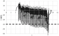
Fig. 9 shows the amplitude (vertical axis, mbar) of the internal negative pressure P as a function of time (horizontal axis, seconds) during a portion of relaxed expiration, wherein the internal negative pressure is not controlled, and wherein the threshold S (-30 mbar, indicated by a dashed line) is reached and exceeded a number of times.
Without an automatic control system, no correction is applied to the pressure cell when the threshold S is reached, resulting in many overshoot events. In this case, the internal negative pressure is maintained above the threshold value for too long. Due to discomfort, the subject prematurely stopped the relaxed exhalation because he had to cough (at 9 seconds on the record, corresponding to less than 7 seconds of exhalation). Finally, the relaxing expiration is not performed for a period of time long enough for the subject to completely empty the air contained in his lungs. Thus, the amount of mucus excreted during relaxed expiration will not be optimal, the treatment is ineffective, and further treatment sessions will be required to achieve satisfactory mucus excretion.
During a second therapy session, a set of negative pressure pulses is generated by means of the pressure unit during a relaxed exhalation of the subject.
According to the method of the invention, during said session:
measuring the internal negative pressure P after each pulse of the subset of pulses by means of the pressure sensor 15,
acquiring the internal negative pressure P measured during the measuring step by means of an acquisition module 31,
comparing the measured internal negative pressure P with a predetermined threshold value S and determining, on the basis of the comparison result, an updated power value to be applied to the pressure unit 13 so that the absolute value of the subsequent internal negative pressure P resulting from said updated power value is below the absolute value of the threshold value S, said comparing and determining steps being performed by means of the calculation module 32,
applying the updated power value to the pressure unit 13 by means of the control module 33 before the next pulse is generated.
The steps of measuring the internal negative pressure P, acquiring the internal negative pressure P, comparing the measured internal negative pressure P with a predetermined threshold S and determining an updated power value, and applying the updated power value are performed before the next pulsation, i.e. in real time, and then iterated.
Fig. 10 shows the amplitude of the internal negative pressure P (vertical axis) at the top and the power value W of the pressure unit (as a percentage of the full power of the pressure unit) at the bottom, both according to time (horizontal axis) during a part of the relaxed breathing, wherein the internal negative pressure is controlled.
It can be observed that when the absolute value of the measured internal negative pressure P exceeds the absolute value of the threshold value S (-30 mbar, indicated by a dashed line), a reduced power value is determined and applied to the pressure unit 13 in real time (see arrows on fig. 10). This causes the internal negative pressure P to decrease in real time, so that it returns below the threshold S.
In this case, the excessive internal negative pressure does not last at least until the next pulse, thereby preventing the internal negative pressure from being maintained above the threshold value for too long, so as not to stop relaxing expiration too early. The automatic control system for the tracheobronchial-air stimulation device of the invention allows to perform a relaxing exhalation for a sufficient period of time (here more than 12 seconds) so as to allow the subject to completely empty the air contained in his lungs, which facilitates the expulsion of mucus during the relaxing exhalation.
With an automatic control system of the tracheobronchial-air stimulation device, the optimal internal negative pressure remains constant during the entire pulse, whereas without the control system the maximum internal negative pressure fluctuates considerably. This results in high respiratory discomfort for the subject, who may feel the need to stop the treatment prematurely.
As shown in fig. 10, by the automatic control, the magnitude of the internal negative pressure P is reduced so that the magnitude of the internal negative pressure P at the end of the relaxation expiration is smaller than the magnitude of the internal negative pressure P at the beginning of the same relaxation expiration. This allows for smooth ending of relaxed exhalation by preparing the lungs to return to normal pressure and prevents the subject from needing a cough. In contrast, it can be observed in fig. 9 that without automatic control, the amplitude of the internal negative pressure P remains substantially constant throughout the relaxation exhalation. This may lead to traumatic consequences for the subject compared to a relaxed exhalation performed with the aid of the inventive automatic control system.