[go: up one dir, main page]

CN115280080A - Method for generating electricity on demand by using geological heat recovery - Google Patents

Method for generating electricity on demand by using geological heat recovery Download PDF

Info

Publication number
CN115280080A
CN115280080A CN202080093036.2A CN202080093036A CN115280080A CN 115280080 A CN115280080 A CN 115280080A CN 202080093036 A CN202080093036 A CN 202080093036A CN 115280080 A CN115280080 A CN 115280080A
Authority
CN
China
Prior art keywords
working fluid
formation
well
energy
power
Prior art date
Legal status (The legal status is an assumption and is not a legal conclusion. Google has not performed a legal analysis and makes no representation as to the accuracy of the status listed.)
Granted
Application number
CN202080093036.2A
Other languages
Chinese (zh)
Other versions
CN115280080B (en
Inventor
马修·特夫斯
贝雷·施瓦茨
约翰·雷德芬
保罗·凯恩斯
Current Assignee (The listed assignees may be inaccurate. Google has not performed a legal analysis and makes no representation or warranty as to the accuracy of the list.)
Eavor Technologies Inc
Original Assignee
Eavor Technologies Inc
Priority date (The priority date is an assumption and is not a legal conclusion. Google has not performed a legal analysis and makes no representation as to the accuracy of the date listed.)
Filing date
Publication date
Application filed by Eavor Technologies Inc filed Critical Eavor Technologies Inc
Publication of CN115280080A publication Critical patent/CN115280080A/en
Application granted granted Critical
Publication of CN115280080B publication Critical patent/CN115280080B/en
Active legal-status Critical Current
Anticipated expiration legal-status Critical

Links

Images

Classifications

    • FMECHANICAL ENGINEERING; LIGHTING; HEATING; WEAPONS; BLASTING
    • F03MACHINES OR ENGINES FOR LIQUIDS; WIND, SPRING, OR WEIGHT MOTORS; PRODUCING MECHANICAL POWER OR A REACTIVE PROPULSIVE THRUST, NOT OTHERWISE PROVIDED FOR
    • F03GSPRING, WEIGHT, INERTIA OR LIKE MOTORS; MECHANICAL-POWER PRODUCING DEVICES OR MECHANISMS, NOT OTHERWISE PROVIDED FOR OR USING ENERGY SOURCES NOT OTHERWISE PROVIDED FOR
    • F03G7/00Mechanical-power-producing mechanisms, not otherwise provided for or using energy sources not otherwise provided for
    • F03G7/04Mechanical-power-producing mechanisms, not otherwise provided for or using energy sources not otherwise provided for using pressure differences or thermal differences occurring in nature
    • FMECHANICAL ENGINEERING; LIGHTING; HEATING; WEAPONS; BLASTING
    • F03MACHINES OR ENGINES FOR LIQUIDS; WIND, SPRING, OR WEIGHT MOTORS; PRODUCING MECHANICAL POWER OR A REACTIVE PROPULSIVE THRUST, NOT OTHERWISE PROVIDED FOR
    • F03GSPRING, WEIGHT, INERTIA OR LIKE MOTORS; MECHANICAL-POWER PRODUCING DEVICES OR MECHANISMS, NOT OTHERWISE PROVIDED FOR OR USING ENERGY SOURCES NOT OTHERWISE PROVIDED FOR
    • F03G4/00Devices for producing mechanical power from geothermal energy
    • F03G4/033Devices for producing mechanical power from geothermal energy having a Rankine cycle
    • F03G4/035Devices for producing mechanical power from geothermal energy having a Rankine cycle of the Organic Rankine Cycle [ORC] type or the Kalina Cycle type
    • FMECHANICAL ENGINEERING; LIGHTING; HEATING; WEAPONS; BLASTING
    • F03MACHINES OR ENGINES FOR LIQUIDS; WIND, SPRING, OR WEIGHT MOTORS; PRODUCING MECHANICAL POWER OR A REACTIVE PROPULSIVE THRUST, NOT OTHERWISE PROVIDED FOR
    • F03GSPRING, WEIGHT, INERTIA OR LIKE MOTORS; MECHANICAL-POWER PRODUCING DEVICES OR MECHANISMS, NOT OTHERWISE PROVIDED FOR OR USING ENERGY SOURCES NOT OTHERWISE PROVIDED FOR
    • F03G4/00Devices for producing mechanical power from geothermal energy
    • F03G4/063Devices for producing mechanical power from geothermal energy with energy storage devices
    • FMECHANICAL ENGINEERING; LIGHTING; HEATING; WEAPONS; BLASTING
    • F03MACHINES OR ENGINES FOR LIQUIDS; WIND, SPRING, OR WEIGHT MOTORS; PRODUCING MECHANICAL POWER OR A REACTIVE PROPULSIVE THRUST, NOT OTHERWISE PROVIDED FOR
    • F03GSPRING, WEIGHT, INERTIA OR LIKE MOTORS; MECHANICAL-POWER PRODUCING DEVICES OR MECHANISMS, NOT OTHERWISE PROVIDED FOR OR USING ENERGY SOURCES NOT OTHERWISE PROVIDED FOR
    • F03G4/00Devices for producing mechanical power from geothermal energy
    • F03G4/069Devices for producing mechanical power from geothermal energy characterised by the brine or scale treatment, e.g. brine desalination, scale deposit prevention or corrosion-proofing
    • FMECHANICAL ENGINEERING; LIGHTING; HEATING; WEAPONS; BLASTING
    • F03MACHINES OR ENGINES FOR LIQUIDS; WIND, SPRING, OR WEIGHT MOTORS; PRODUCING MECHANICAL POWER OR A REACTIVE PROPULSIVE THRUST, NOT OTHERWISE PROVIDED FOR
    • F03GSPRING, WEIGHT, INERTIA OR LIKE MOTORS; MECHANICAL-POWER PRODUCING DEVICES OR MECHANISMS, NOT OTHERWISE PROVIDED FOR OR USING ENERGY SOURCES NOT OTHERWISE PROVIDED FOR
    • F03G4/00Devices for producing mechanical power from geothermal energy
    • F03G4/072Controlling or monitoring
    • FMECHANICAL ENGINEERING; LIGHTING; HEATING; WEAPONS; BLASTING
    • F24HEATING; RANGES; VENTILATING
    • F24TGEOTHERMAL COLLECTORS; GEOTHERMAL SYSTEMS
    • F24T10/00Geothermal collectors
    • F24T10/10Geothermal collectors with circulation of working fluids through underground channels, the working fluids not coming into direct contact with the ground
    • FMECHANICAL ENGINEERING; LIGHTING; HEATING; WEAPONS; BLASTING
    • F24HEATING; RANGES; VENTILATING
    • F24TGEOTHERMAL COLLECTORS; GEOTHERMAL SYSTEMS
    • F24T10/00Geothermal collectors
    • F24T10/20Geothermal collectors using underground water as working fluid; using working fluid injected directly into the ground, e.g. using injection wells and recovery wells
    • FMECHANICAL ENGINEERING; LIGHTING; HEATING; WEAPONS; BLASTING
    • F24HEATING; RANGES; VENTILATING
    • F24TGEOTHERMAL COLLECTORS; GEOTHERMAL SYSTEMS
    • F24T10/00Geothermal collectors
    • F24T2010/50Component parts, details or accessories
    • F24T2010/56Control arrangements
    • YGENERAL TAGGING OF NEW TECHNOLOGICAL DEVELOPMENTS; GENERAL TAGGING OF CROSS-SECTIONAL TECHNOLOGIES SPANNING OVER SEVERAL SECTIONS OF THE IPC; TECHNICAL SUBJECTS COVERED BY FORMER USPC CROSS-REFERENCE ART COLLECTIONS [XRACs] AND DIGESTS
    • Y02TECHNOLOGIES OR APPLICATIONS FOR MITIGATION OR ADAPTATION AGAINST CLIMATE CHANGE
    • Y02EREDUCTION OF GREENHOUSE GAS [GHG] EMISSIONS, RELATED TO ENERGY GENERATION, TRANSMISSION OR DISTRIBUTION
    • Y02E10/00Energy generation through renewable energy sources
    • Y02E10/10Geothermal energy
    • YGENERAL TAGGING OF NEW TECHNOLOGICAL DEVELOPMENTS; GENERAL TAGGING OF CROSS-SECTIONAL TECHNOLOGIES SPANNING OVER SEVERAL SECTIONS OF THE IPC; TECHNICAL SUBJECTS COVERED BY FORMER USPC CROSS-REFERENCE ART COLLECTIONS [XRACs] AND DIGESTS
    • Y02TECHNOLOGIES OR APPLICATIONS FOR MITIGATION OR ADAPTATION AGAINST CLIMATE CHANGE
    • Y02EREDUCTION OF GREENHOUSE GAS [GHG] EMISSIONS, RELATED TO ENERGY GENERATION, TRANSMISSION OR DISTRIBUTION
    • Y02E10/00Energy generation through renewable energy sources
    • Y02E10/40Solar thermal energy, e.g. solar towers
    • Y02E10/46Conversion of thermal power into mechanical power, e.g. Rankine, Stirling or solar thermal engines
    • YGENERAL TAGGING OF NEW TECHNOLOGICAL DEVELOPMENTS; GENERAL TAGGING OF CROSS-SECTIONAL TECHNOLOGIES SPANNING OVER SEVERAL SECTIONS OF THE IPC; TECHNICAL SUBJECTS COVERED BY FORMER USPC CROSS-REFERENCE ART COLLECTIONS [XRACs] AND DIGESTS
    • Y02TECHNOLOGIES OR APPLICATIONS FOR MITIGATION OR ADAPTATION AGAINST CLIMATE CHANGE
    • Y02EREDUCTION OF GREENHOUSE GAS [GHG] EMISSIONS, RELATED TO ENERGY GENERATION, TRANSMISSION OR DISTRIBUTION
    • Y02E10/00Energy generation through renewable energy sources
    • Y02E10/70Wind energy
    • Y02E10/72Wind turbines with rotation axis in wind direction
    • YGENERAL TAGGING OF NEW TECHNOLOGICAL DEVELOPMENTS; GENERAL TAGGING OF CROSS-SECTIONAL TECHNOLOGIES SPANNING OVER SEVERAL SECTIONS OF THE IPC; TECHNICAL SUBJECTS COVERED BY FORMER USPC CROSS-REFERENCE ART COLLECTIONS [XRACs] AND DIGESTS
    • Y02TECHNOLOGIES OR APPLICATIONS FOR MITIGATION OR ADAPTATION AGAINST CLIMATE CHANGE
    • Y02EREDUCTION OF GREENHOUSE GAS [GHG] EMISSIONS, RELATED TO ENERGY GENERATION, TRANSMISSION OR DISTRIBUTION
    • Y02E70/00Other energy conversion or management systems reducing GHG emissions
    • Y02E70/30Systems combining energy storage with energy generation of non-fossil origin

Landscapes

  • Engineering & Computer Science (AREA)
  • Chemical & Material Sciences (AREA)
  • Combustion & Propulsion (AREA)
  • Life Sciences & Earth Sciences (AREA)
  • Mechanical Engineering (AREA)
  • General Engineering & Computer Science (AREA)
  • Sustainable Energy (AREA)
  • Sustainable Development (AREA)
  • Water Supply & Treatment (AREA)
  • Hydrology & Water Resources (AREA)
  • Engine Equipment That Uses Special Cycles (AREA)
  • Other Liquid Machine Or Engine Such As Wave Power Use (AREA)
  • Investigation Of Foundation Soil And Reinforcement Of Foundation Soil By Compacting Or Drainage (AREA)
  • Processing Of Solid Wastes (AREA)
  • Management, Administration, Business Operations System, And Electronic Commerce (AREA)
  • Supply And Distribution Of Alternating Current (AREA)

Abstract

公开了在各种实施例中用于向终端用户按需提供电力的方法。闭合环路热回收布置被设置在具有预定潜在热输出容量的地质地层内。发电设备被并入到该环路中以回收能量。工作流体在该环路内以变化的流速循环,以使热输出关于预定的潜在热输出容量振荡,以按需生产电力,其中平均热输出可以等于该预定的潜在热输出容量。提供了与间歇性可再生能源的整合,其优化了性能和配电。

Figure 202080093036

Methods are disclosed in various embodiments for providing power on demand to end users. A closed loop heat recovery arrangement is provided within a geological formation having a predetermined potential heat output capacity. Power plants are incorporated into the loop to recover energy. The working fluid circulates within the loop at varying flow rates to oscillate the heat output about a predetermined potential heat output capacity, where the average heat output may be equal to the predetermined potential heat output capacity, to produce electricity on demand. Provides integration with intermittent renewable energy that optimizes performance and power distribution.

Figure 202080093036

Description

Method for generating electricity on demand by using geological heat recovery
Technical Field
The present invention relates to closed loop energy recovery from geological formations having extractable heat, and more particularly, to a method of providing energy on demand using a closed loop production system.
Background
Previous activities in the field of geological heat/electricity production have been well documented. One of the early examples is found in U.S. patent publication 20120174581 by Vaughan et al, published on 7/12/2012.
Other examples include Mickelson U.S. patent publication 2007024572, published on 21/4/2004, mcHargue U.S. patent publication 201100480, published on 26/8/2009, lakic U.S. patent No. 8,281,591, published on 9/10/2012, and Muir et al U.S. patent No. 10,527,026, published on 7/1/2020.
These references represent a pioneering development in the prior art for heat recovery for power generation. Although useful, they are not instructive or authoritative in addressing the power production needs and how they are mixed with intermittent renewable energy sources.
Intermittent renewable energy sources have recently become competitive with fossil fuel prices and now produce a large portion (30-45%) of electricity in certain jurisdictions (california, germany, etc.).
These carbon-free sources have the potential to substantially reduce greenhouse gas emissions. However, the amount of solar/wind energy that can enter the grid is limited due to the inherent intermittency of energy generation. These intermittent or variable generation sources are also referred to as non-schedulable.
The high prevalence of solar/wind energy in the grid has led to problems with system integration, since it is difficult to replace the energy produced without sunlight and without wind. This concentration is reflected in california, where there is a high solar energy prevalence and a so-called "duck curve" (duck curve) is formed; (https://en.wikipedia.org/wiki/Duck_ curve)。
At present, solar power stations cannot be built in the state of california without some energy storage measures, typically 2-4 hours of lithium ion battery storage. However, the true energy storage capacity of 8 hours or more is very expensive.
From NREL "Power Generation Baseline report" ((R))https://www.nrel.gov/docs/fy17osti/67645.pdf) A comprehensive report on power sources is written describing the problem of integrating non-dispatchable technologies. Currently, there is no feasible solution to decarbonise the remaining approximately 50% of the grid.
Another problem with integrating intermittent renewable energy sources is that they tend to fall very quickly, known as a fast ramp down. Thus, one important and valuable feature desired in a dispatchable power supply is the ability to "ramp" up to offset the rapid decline in wind/solar energy. Many technologies lack this ability to ramp quickly (e.g., coal, nuclear, and some types of gas power generation cannot ramp quickly).
The challenge is to develop a cost effective energy system to schedule nighttime and nighttime loads when solar/wind energy is not available.
Traditional geothermal heat appears to be a natural choice to provide renewable dispatchable power. However, conventional geothermal systems operate at base load due to several fundamental problems that hinder the ability to provide flexible/schedulable power output.
Fluids from geothermal reservoirs cannot be accelerated without incurring large parasitic pumping losses. This is due to darcy and fracture flow regimes within the rock reservoir; a large amount of energy is required to accelerate the flow rate above the normal base load operating point.
The reservoir may be pressurized, however, this may result in loss of reservoir seal, initiation of fracturing, and induction of earthquakes.
In addition to the parasitic losses that offset any total power increase in the grading process, in conventional geothermal, there are many operational problems due to large up and down grading of flow rates, sand production, liner failure, pump operating range, liquid/gas flow regime variability, thermal expansion and cooling processes leading to geomechanical problems within the reservoir, injection well plugging, etc.
Bidding book of the U.S. department of energy (https://www.sbir.gov/sbirsearch/detail/1523867) Note that: "schedulable power generation" refers to a power source that may be turned on or off or whose power output may be adjusted according to an order. Geothermal power plants are typically used for base load power, rather than dispatchable power. The 8MW pervasion Facility in hawaii is the first fully dispatchable geothermal power plant (nordqquist et al, GRC Transactions, volume 37, 2013). As described by the Ormat group, it is not easy to retrofit base load power plants to full schedulability. The power plant needs to adjust its power output quickly to respond to the required ramp rate and maintain its frequency within close tolerances of the grid power. This is a challenge for geothermal power plants because the heat source cannot naturally respond quickly to changes in demand. To address this challenge, ormat decides to maintain the geothermal fluid flowing at a relatively steady rate while bypassing the power plant as needed. At part load, some geothermal fluid is pumped to the surface, bypassing the power plant, and re-injected into the ground without extracting any useful enthalpy. This approach is robust, but necessarily results in high parasitic power consumption at part load due to constant full flow pumping power requirements. "
The geothermal reservoir (underground system) in the above example is not producing at full capacity. So-called schedulability is actually only based on operating the geothermal underground capacity at a low capacity factor or, most of the time, operating the system at a potential heat output capacity below the geothermal system and, at the time of scheduling, at a potential heat output capacity equal.
Other researchers have focused on using the underground as a storage medium for compressed air energy storage for air reservoirs; in the articlehttps://asmedigitalcollection.asme.org/memagazineselect/article/137/12/36/ 380449/Earth-BatteryCarbon-Dioxide-Sequestration-UtilityCO2 or pressurized water. These systems all suffer from similar disadvantages. The key issue is that they are open systems (the volume of working fluid within the system is constantly changing) and therefore face the challenge of controlling and managing flow in porous media and a large number of variable fracture networks. Furthermore, they are primarily energy storage systems, not energy generation systems.
Still other researchers are studying the use of Thermal Energy Storage (TES), i.e. a system that stores heat generated by geothermal systems at the surface, to optimize the end user's daily energy output. However, one key challenge is the temperature loss caused by sensible heat (sensible heat) exchangers, and the resulting lower round-trip efficiency. Furthermore, the installation cost of large-scale high temperature TES suitable for power generation is currently prohibitive.
A very different but still related prior art area is the cryogenic underground thermal energy storage system. These are of two types, borehole Thermal Energy Storage (BTES) and Aquifer Thermal Energy Storage (ATES). Ats and BTES are essentially cryogenic heat pump systems that store and extract seasonal energy from summer to winter, and vice versa. BTES stores the heat of the air conditioner waste heat in summer, via heat conduction with surrounding rocks, and then extracts the heat in winter. Neither ats nor BTES are energy generation systems, nor even simple energy storage systems. Instead, they work with energy driven heat pumps, and the entire system is an energy consumer, albeit more efficient than standard AC and space heating technologies.
Cryogenic air storage is an attractive technology for storing excess electricity generated by renewable systems and discharging it when neededAnd (4) electricity. When used in combination with geothermal heat, the round trip efficiency of storage technology increases. Several researchers have studied this type of integration, for example
Figure BDA0003745643720000041
In Geothermol, low-temperature energy storage driven by geothermal energy, volume 77, geothermol, 2018).
The above-mentioned academic papers consider geothermal systems operating in base load mode, rather than the dispatchable geothermal systems disclosed herein. The main challenge with this approach and other prior art is that low temperature discharge occurs at several peak hours, however geothermal output is base load (i.e. a smooth output over 24 hours).
What is needed to improve the current technology and base load limiting issues is a new paradigm that can provide power to end users on demand at any time, and supplement and optimize intermittent renewable energy sources when needed.
The present technology, which will be discussed further herein, addresses all of the problems currently in power generation, infrastructure, and distribution, without relying on a base load source, non-dispatchable renewable energy source, or batteries.
Disclosure of Invention
It is an object of one embodiment of the present invention to provide a method of producing dispatchable, scalable and fast ramping power using a closed loop engineering geological heat recovery system.
It is a further object of an embodiment of the invention to provide a geothermal power output system having a base load distribution substantially equivalent to an oscillatory discontinuous output period averaged over a distribution period.
It is a further object of an embodiment of the present invention to provide a method for optimizing a characteristic potential heat output capacity of a well system, the well system including a working fluid thermally chargeable from a formation, the system having an inlet well and an outlet well and disposed within the formation having the characteristic potential heat output capacity, the method comprising: the circulation of the working fluid within the well system is regulated to oscillate the heat output from the thermally charged working fluid with respect to the predetermined potential heat output capacity of the property, wherein the average oscillating heat output is approximately equal to the predetermined potential heat output capacity of the formation.
In this embodiment, the heat output is unstable and cycles between a charging operation to thermally charge the working fluid by conduction of heat from the formation and a discharging operation to remove thermal energy for treatment.
The processing may include conversion to at least one of electrical energy, thermal energy, and combinations thereof.
In terms of regulation, this may take many forms, including at least one of a change in the flow rate of the working fluid, residence time in the system, duration of oscillation, duration of thermal charging, thermal discharging, and combinations thereof.
The practice of this method allows for the on-demand generation of energy for the end user through the interaction between the charged working fluid and the power generation equipment.
It is another object of an embodiment of the present invention to provide a method of providing on-demand power to an end user using a well system having an entry well and an exit well in a heat-producing geological formation (geological formation), the method comprising: forming a closed loop with a power generation device operatively connecting the inlet and the outlet; circulating a working fluid in the loop at a predetermined residence time to load the circulating working fluid with conductive heat from the formation; and adjusting a flow rate of the thermally loaded working fluid within the loop for power generation based on the user demand.
Depending on the specific parameters pertaining to the formation, the entry well and the exit well may be operatively and fluidly connected with an interconnected section configured for conduction in the thermogenic geological formation.
To enhance heat recovery and networking of the well system, as well as many other advantages, the entry well and the exit well may be connected with a plurality of interconnected sections in a predetermined pattern within the formation. Due to applicants' patents and published techniques, patterning of well systems, interconnect segments, well system networks is simplified and not limited from a system design perspective.
For power generation, output management and schedulability, selective adjustment of working fluid circulation may be performed within a predetermined section of a plurality of interconnected sections of a well system to oscillate heat output from a thermally charged working fluid with respect to a predetermined potential heat output capacity of a property of a formation, wherein an average oscillating heat output is approximately equal to the predetermined potential heat output capacity of the formation.
Where the well system comprises a plurality of well systems having a plurality of interconnected sections, selective adjustment of the working fluid may be effected in each interconnected section of the well system, in some or all of the interconnected sections, at a particular time and in a particular sequence and in a user-selected manner with adjacent well systems.
The method is based on flexibility of deployment and therefore any geological formation with a temperature above 90 ℃ can be mined regardless of the rock type, i.e. high permeability, low permeability, hot dry rock, geothermal formations, sedimentary formations, volcanic formations, variable permeability formations and combinations thereof. To increase flexibility, the method is not limited by rock formation inconsistencies, i.e., naturally cracked, fractured or cracked rock, synthetically cracked, fractured or cracked rock, and combinations thereof. The method can be applied to any scene.
In terms of working fluids, the desired fluid may be water, which may include drag reducing additives such as surfactants, polymeric compounds, suspensions, biological additives, stabilizers, scale inhibitors, corrosion inhibitors, drag reducing agents, anti-freeze chemicals, biocides, hydrocarbons, alcohols, organic fluids, and combinations thereof.
Other suitable fluids may include supercritical carbon dioxide, lower alkanes, e.g., C1-C10, fluids containing phase change materials, refrigerants. These examples are numerous and can be easily derived from the prior art.
Additives that promote maintenance of the well system are contemplated for use in the working fluid as compounds that enhance the thermodynamic efficiency of the working fluid.
It is a further object of an embodiment of the present invention to provide a method of providing energy on demand to an end user using a geothermal mechanism comprising an entry well, an exit well and an interconnected segment therebetween in a geological formation, the method comprising: forming a closed geothermal loop using a power plant connecting the inlet and the outlet; circulating a working fluid in the loop at a predetermined residence time to load the circulating working fluid with conductive heat from the formation; and adapting a flow rate of the thermally loaded working fluid within the loop based on user demand.
The geothermal wells and interconnecting sections may be newly formed or existing. If existing, the methods herein can be readily adapted to retrofit existing devices to increase efficiency.
Depending on the proposed end use, the energy may be electrical or thermal, with a residence time sufficient to facilitate power generation for the duration of the user's demand.
Interaction between the charged working fluid and the power generation equipment within the loop includes minimizing residence time by increasing the flow rate of the charged working fluid.
To further increase efficiency, thermal energy from the charged working fluid may be stored in the geothermal formation, and the working fluid may be supplemented with an energy charged working fluid from an adjacent well in the formation. Replenishment may take the form of rerouting of the working fluid from adjacent wells to the wells and power generation equipment according to user demand.
It is another object of an embodiment of the present invention to provide a method of delivering power on demand to an end user, comprising: providing an inlet well, an outlet well, and a well interconnecting section between the inlet well and the outlet well and disposed within a subterranean formation having a temperature of at least 90 ℃, the subterranean formation having a predetermined potential heat capacity; implementing a closed loop arrangement within the formation by connecting the outlet well to a power generation apparatus to recover energy from the well arrangement in a closed loop between the well and the power generation apparatus, the closed loop arrangement having a predetermined energy output within the available potential heat capacity; circulating a working fluid in the loop at least within the interconnected section at a predetermined dwell time to maximize energy transfer from the formation to form an energy charged working fluid; and generating energy on demand for an end user through interaction between the charged working fluid and the power generation equipment.
Consistent with the established flexibility of the present method, the interconnected sections may be cased, uncased, lined, chemically treated to enhance electrical conductivity, chemically sealed, self-healing when sealed, heat sealed, including combinations of optionally perforated single tubes, optionally perforated coaxial tubes, and continuous or discontinuous configurations thereof. The working fluid may be designed to maintain the integrity of the wellbore by sealing a breach or resulting permeability. If the wellbore is at risk of caving or collapse, the fluid density may be increased to provide sufficient compressive strength on the formation. Conversely, if the formation is sufficiently cooled, it may be at risk of tensile failure, in which case a fluid having a reduced density may be selected.
The working fluid may be circulated within the loop at a varying flow rate to oscillate the heat output with respect to a predetermined energy output capacity to produce electricity on demand, wherein the average heat output may be equal to the predetermined potential heat output capacity.
In an alternative embodiment, a plurality of interconnected sections (multilateral) common to the entry and exit wells are provided in a configuration to maximize heat recovery from the thermal gradient of the formation. The entry well and exit well may be co-located if the footprint of the arrangement is an issue.
In a further alternative embodiment, to exploit thermal gradients within the formation, the interconnect sections may be arranged to: symmetrical with respect to adjacent interconnect segments, asymmetrical with respect to adjacent interconnect segments, interdigitated with adjacent interconnect segments, coplanar with adjacent interconnect segments, parallel planar with adjacent interconnect segments, in a separate or grouped network, and suitable combinations thereof.
To improve power distribution, as will be further explained below, a plurality of closed loops with adjacent loop outlet wells can be selectively connected to the inlet wells of additional wells in a daisy chain configuration that can be further valved for selection by a user.
It is another object of an embodiment of the invention to provide a method for optimizing power distribution on a pre-existing power grid, comprising: providing an intermittent power generation arrangement having a designed maximum power generation and a second effective power generation on a pre-existing power grid; positioning an energy recovery and production closed loop within a heat-bearing subterranean formation adjacent to the intermittent power generation arrangement, the loop including an inlet well, an outlet well, an interconnected section between the inlet well and the outlet well, the interconnected section positioned in the formation to facilitate heat recovery in the formation, the formation having available latent heat capacity; positioning the closed loop in a configuration within the formation to produce a predetermined energy output from the available latent heat capacity; circulating a working fluid within the loop for a predetermined residence time to thermally charge the circulating working fluid by conduction from the formation; and selectively thermally discharging the working fluid through an intermittent power generation arrangement to increase power generation to an amount above the second effective power generation amount and below a designed maximum power generation amount, thereby optimizing total power generation using the pre-existing power grid.
The intermittent power generation arrangement and the energy recovery and production closed loop may be located on a common geographical footprint to produce energy on demand.
The selective thermal discharge of the working fluid by the intermittent power generation arrangement is achieved during periods of significant customer power demand and is transmitted using the transmission capacity and infrastructure of the pre-existing electrical grid of the intermittent power generation arrangement. Intermittent energy sources are well known as wind, solar and battery energy sources.
It is another object of an embodiment of the present invention to provide a method of generating electricity, comprising: providing a power transmission grid for transmitting the produced power to an end user, the grid having an output capacity; providing a power generation arrangement on the power grid having a designed maximum power generation and a second effective power generation; positioning an energy recovery and production closed loop within a heat-bearing subterranean formation adjacent to the intermittent power generation arrangement, the loop including an inlet well, an outlet well, an interconnected section between the inlet well and the outlet well, the interconnected section positioned in the formation to facilitate heat recovery in the formation, the formation having available latent heat capacity; positioning the closed loop in a configuration within the formation to produce a predetermined energy output from the available latent heat capacity; circulating a working fluid within the loop at a predetermined residence time to thermally charge the circulating working fluid by conduction from the formation; and selectively thermally discharging the working fluid through the power generation arrangement to maintain the amount of power generated throughout the grid at the capacity.
The grid may include a plurality of individual power distribution areas for distributing power within a geographical area, at least some of the power distribution areas including energy recovery and production closed loops.
It is therefore another object of an embodiment of the present invention to provide a power plant for providing a predetermined distribution to a user, comprising: a thermal energy recovery device configured to regulate circulation of a working fluid in the heat producing formation whereby thermal energy is transferred into the working fluid, the device for oscillating discrete output periods averaged over a power distribution period; and a power distribution device for distributing the average power output as a user-predetermined power output.
Having thus described the invention in general terms, reference will now be made to the accompanying drawings.
Industrial applicability
The techniques herein may be applied in the fields of energy recovery and power generation.
Drawings
FIG. 1 is a schematic illustration of an energy recovery arrangement disposed in a heat-bearing geological formation;
fig. 2A-2D are schematic diagrams of alternative interconnected or multi-sided segments for use in a retrieval arrangement;
FIG. 3 is an alternative to the recovery arrangement;
FIG. 4 is a graphical representation of a series of operational scenarios depicting temperature (heat output) as a function of time for each scenario;
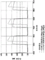
FIG. 5 is a graph similar to FIG. 4, presenting data over several days;
FIG. 6 is a schematic diagram of heat output over 30 years for the particular scenario referenced in FIGS. 4 and 5;
FIG. 7 is a schematic diagram of a dispatchable geothermal system integrated with other non-dispatchable renewable energy sources;
FIG. 8 is a schematic diagram of a plurality of schedulable geothermal loops in a network;
FIG. 9 is a flow chart illustrating a process of planning, controlling and optimizing the integration of non-dispatchable renewable energy sources with dispatchable geothermal systems;
FIG. 10 is a schematic diagram of the combined power output capacity of the generator network;
FIG. 11 is a schematic diagram of mitigating grid saturation with an intermittent power source; and
fig. 12 is a schematic diagram of an alternate embodiment of the invention.
Like numbers refer to like elements throughout.
Detailed Description
Referring now to the drawings, FIG. 1 shows an example of a general arrangement for practicing embodiments of the methods described herein. The numeral 10 generally designates a general arrangement. The temperature of the geological formation 12 having thermal energy is at least 90 ℃ and may typically be above 150 ℃, or even 600 ℃ or higher, the geological formation 12 comprising a subterranean loop arrangement having an entry well 14 and an exit well 16, the entry well 14 and the exit well 16 may be co-located, interconnected with at least one interconnected section 18. In the example, several sections 18 are depicted. The thermal gradient will depend on the formation properties.
At the ground 20, the inlet 14 and outlet 16 are connected to a power generation facility 22. The device 22 completes a loop arrangement of a closed loop, which will be referred to as L for simplicity. It will be apparent that in order to recover thermal energy from the surrounding formation 12, a section 18 is provided within the geological formation. For clarity, the closed loop L and in particular the section 18 may comprise fractures, breaks, fissures within which fluid may be transported, however, this does not deviate from the gist of the closed loop concept; despite the fact that there may be localized multidirectional flow anomalies, the flow pattern remains closed in the combination of inlets, interconnections, outlets, elements of the power generation equipment 22.
The geological formation may be any formation that provides temperature as described above. In this regard, examples include geothermal formations, low permeability formations, hot dry rock, sedimentary formations, volcanic formations, high temperature formations, variable permeability formations, and combinations thereof. These are examples only; any number of other formations are within the scope of the present invention.
Depending on its nature, the formation will have a predetermined potential heat output capacity, which can be pre-analyzed by suitable techniques known to those skilled in the art. Of course, each formation will have a different output capacity.
In this regard, each loop L will have a predetermined potential heat output capacity that reflects its design parameters, such as the number of sections 18, its geometric arrangement, depth, length, formation temperature, formation rock properties, and the like. All these parameters will be apparent to the skilled person.
For recovery, the working fluid circulates through loop L and exits outlet well 16, flows through a power plant 22 that converts thermal and/or kinetic energy into electricity for use by an end user, generally designated by numeral 24, and/or is redistributed at 26 for alternate uses as will be discussed below. Once circulated as shown, the working fluid is reintroduced into the inlet 14.
By circulating the working fluid through the closed loop L at a relatively low flow rate during the charging period, the working fluid is thermally "charged" or loaded. The residence time of the working fluid within the subsurface flow path increases, and thus the fluid is heated to a high temperature via heat transfer with the surrounding formation 12.
The system is "discharged" by significantly increasing the flow rate and flushing out the volume of heated working fluid within the hot subsurface portion of the closed loop L.
The working fluid may comprise water, supercritical carbon dioxide, and the like, and includes drag reducing additives such as surfactants, polymeric compounds, suspensions, biological additives, stabilizers, scale inhibitors, corrosion inhibitors, drag reducing agents, antifreeze chemicals, biocides, hydrocarbons, alcohols, organic fluids, and combinations thereof. Other suitable examples will be appreciated by those skilled in the art. It is contemplated that the composition of the working fluid may be dynamically changed in the event of changes in the thermal properties of the subsurface.
Referring now to fig. 2A, 2B, 2C, and 2D, schematic diagrams of possible configurations and combinations of the interconnect segments 18 are shown. The figure generally illustrates that adjacent interconnect segments can be symmetric, asymmetric with respect to adjacent interconnect segments, interdigitated with adjacent interconnect segments, coplanar with adjacent interconnect segments, parallel planar with adjacent interconnect segments, in isolated or grouped networks, and combinations thereof. The specific geometric configuration will vary depending on the temperature gradient characteristics. The drawings are exemplary only; the designer will be aware of suitable variations.
FIG. 3 shows an example where the loop L includes a plurality of interconnected sections 18, where the output 16 of one section 18 serves as the input 14 to an adjacent section 18, collectively collected at the power plant 22. In this way, the loop L is subdivided into a daisy chain configuration for the operation of the method.
The potential heat output capacity is the maximum sustainable thermal energy output of the system. The heat output can be temporarily changed using the methods disclosed herein, but the long-term average output (i.e., average over months or years) cannot exceed the potential heat output capacity.
The overall geothermal efficiency of the system is equal to the average heat output divided by the potential heat output capacity, which is commonly referred to as the geothermal "capacity factor". It is advantageous to have a high capacity factor, or a high utilization of the potential heat output capacity available. Conventionally, this is achieved by a constant heat output at or near the potential heat output capacity. Many geothermal systems operate in this manner at a capacity factor greater than 90%, sometimes referred to as "base load" operation. The disclosed method enables a high geothermal heat capacity factor while also providing a flexible on-demand energy output rather than a constant output.
Fig. 4 shows an example of transient thermodynamic modeling based on the closed loop multilateral system described in applicant's co-pending application No. pct/CA2019000076, etc. The inputs to the thermodynamic model are shown in the table below.
FIG. 4 exemplary data
Figure BDA0003745643720000141
Figure BDA0003745643720000151
The figure shows three operational scenarios of the same geothermal loop: operating at a constant flow rate base load (base case), in which case the heat output is equal to the potential heat output capacity; run with a charge at 33kg/s for 16 hours and then a discharge at 130kg/s for 8 hours; and a charge at a rate of 30kg/s for 12 hours and then a discharge at a rate of 100kg/s for 12 hours.
Typically, the charging cycle will be performed when the energy price is low or the renewable energy supply is variable. This allows the interconnected section 18 previously mentioned herein to recover thermal energy from the formation.
Figure 5 shows the highlight detail over the 3 day time range. If the system is operating in a base load mode, the average flow rate over the combined charge/discharge cycle is approximately equal to the optimum fixed flow rate. In this example, if operating in base load mode, the same subterranean well arrangement as shown in the previous figures will always equal the potential heat output capacity at a flow rate equal to 60L/s. Colloquially, the system will operate with full underground geothermal capacity. This is a key distinction from some prior art (promat's oramat) where the average geothermal output of the combined "charge" and "discharge" cycles is significantly lower than the long-term capacity.
The charging cycle establishes a strong thermosiphon driven by the density difference of the cold fluid in the inlet well 14 relative to the hot fluid in the outlet well 16. During the charging cycle, the thermosiphon pressure drives a pressure higher than that required to maintain the desired flow rate. Thus, the flow rate is controlled by applying a pressure drop using a flow control valve or other device (not shown) to inhibit flow downstream of the outlet well 16. The flow control valve is automatic and can be controlled by software that uses a thermodynamic model to calculate the desired position of the valve. The control valve also helps manage the pressure in the subterranean loop to maintain it within desired limits based on the density of the working fluid and the pump discharge pressure.
When discharging, the flow rate can be immediately increased by releasing the choke valve (opening the control valve). This near instantaneous increase in flow rate enables a fast ramp capability. The flow rate can be increased until the hydraulic loss through the closed loop equals the thermosiphon pressure drive.
The use of a pump can increase the flow beyond this level, which would require a parasitic power load. However, as long as most of the pressure drive is generated by the thermosiphon effect, parasitic loads are practically acceptable.
Using these methods, the flow rate can be controlled to match the power output to the end user's requirements through the charge-discharge cycle and the residence time of the working fluid in the loop.
In the flow in conventional open geothermal systems or porous media of the prior art, the pumping pressure required to achieve high flow rates at discharge results in unacceptably high parasitic pump loads and significantly reduces or eliminates any gain in net power output. It has been found that practical limits are reached when the ratio of pressure loss in the circuit (circuit) to thermosiphon pressure drive is about 1.5. The system must be designed with hydraulic losses less than 1.5 times the thermosiphon pressure drive. Ideally, the pressure loss is less than 1 times the thermosiphon drive and the entire flow is driven by the thermosiphon. Therefore, there is no parasitic pump load.
Energy is stored in the working fluid itself. During the charging cycle, sufficient dwell time is required to heat the working fluid to accommodate the discharge cycle. For example, if the discharge period is typically 8 hours long, the fluid circuit transit time must be at least 8 hours (average of discharge and charge periods).
Energy may also be temporarily stored in the rock near the subsurface flow path and exit well 16 during the charging cycle. At low flow rates, heat is conductively transferred from hotter rocks in the formation 12 into the working fluid, and as the fluid progresses through the system, it encounters cooler rocks (typically shallower, e.g., in the exit well 16), where energy is transferred from the fluid to the cooler rocks and temporarily stored. During the discharge period, the average fluid temperature drops and the stored heat is transferred back to the working fluid.
The closed loop avoids the operational problems of conventional geothermal systems, which are exacerbated when the flow rates vary dramatically, as discussed herein. For example, common operational problems are caused by brine, solids, fouling, plugging, and dissolved gases.
The schedulability disclosed herein integrates well with cryogenic air storage (CES), hydrogen production, or other systems that use stored electrical energy. An example of a process flow is shown below. The CES charging cycle may use inexpensive excess power from the grid or co-located renewable energy sources (e.g., solar energy during peak daytime hours). CES may also be charged using produced geothermal energy, but this is not essential. In one embodiment, the geothermal system will produce a fixed amount of power throughout the charge and discharge cycle. The increase in thermal energy produced during the discharge cycle is used to heat the air stream from the CES process prior to expansion in the turbine.
There are several advantages to using CES with schedulable geothermal:
the heat engine (which converts thermal energy to electricity) is sized only for the charge cycle, not the peak output of the discharge cycle, thereby greatly reducing equipment and asset costs.
Less additional facilities are required to supply heat to the CES facility.
CES discharges only during a few peak hours of the day. The schedulable discharge period of the geothermal system may match the CES discharge period.
Fig. 6 shows the 30-year heat output for the "base case" and the "8-hour schedulable case" mentioned in the previous figures. The base case operates at base load and equals the available heat output capacity, while the "8 hour dispatchable case" while operating at dispatchable output, achieves an effective capacity factor of about 97% and is therefore approximately equal to the predetermined potential heat output capacity of the formation.
This illustrates the main invention that the output can be schedulable while still maintaining a high geothermal capacity factor, typically over 80% and close to 100%.
The transient thermodynamic simulation described above was tested in a prototype geothermal system in the middle of alberta, canada. The system comprised a 2.4km deep polygonal U-tube heat exchanger and was 2.5km from site to site on the ground. The results verify the modeling and demonstrate that schedulability can be predicted and controlled by adjusting the flow rate using an automatic control valve at the outlet well in this embodiment. Empirical results demonstrate that the system is very fast ramping and when combined with a power generation system such as an Organic Rankine Cycle (ORC), can meet the fast ramping requirements integrated with solar energy systems.
Fig. 7 illustrates how a dispatchable geothermal system may be used when integrated with other non-dispatchable renewable energy sources. The system is turned down during peak solar hours and is ramped up as solar energy falls. The schedulable geothermal fills the gap between energy demand and non-schedulable renewable energy sources. This is merely an example, and the output may be modified to match any combination of charge/discharge cycles, and the flow rate may be varied to meet any shape of output within physical limits.
Solar power generation is used as an example, however, the same schedulable mechanism may be used to integrate into a direct heat utilization application, such as a zone heating system or a zone cooling system.
Fig. 8 illustrates a plurality of schedulable geothermal loops in a network. The charge/discharge cycle can be predetermined for each loop so that the total output meets the desired shaped output curve. An automated control system coupled to a thermodynamic model is used to control flow rate, thermosiphon, and temperature in each loop. The charge and discharge cycles may be sequential or simultaneous, depending on the circumstances and the parameters of each loop.
FIG. 9 is a process flow diagram for planning, controlling and optimizing the integration of non-dispatchable renewable energy sources with dispatchable geothermal. A power grid system is provided having a time-varying demand profile, existing supply profiles from different non-dispatchable renewable resources (e.g., PV, wind, base load nuclear, etc.), the control technique optimizing the network of dispatchable renewable geothermal generators to fill the gap between the existing non-dispatchable supply and demand profiles. The optimization parameter may be to meet a net demand, or may be to maximize the received price or revenue (price multiplied by volume), or any other combination of factors. These may form only part of the optimization/scheduling algorithm.
In a network of dispatchable geothermal loops, a network of power generation modules (not shown) will be utilized which convert potential energy and thermal energy to electricity. These power generation systems may be ORCs, flash plants, pressure driven systems, direct turbines, or any other conversion component. The power generation modules may be arranged in series or parallel or in combination. The control system directs the flow from each geothermal loop to the appropriate conversion module based on proximity, scheduling, temperature, and other relevant factors.
Fig. 10 shows the combined power output capacity of the generator network, which is necessarily higher than the potential heat output capacity of the geothermal loop network. The power generation capacity is designed to meet the peak output of the geothermal network at the time of dispatch, which can be set to meet the peak demand from the end users. The figure illustrates that while the underground system has a high geothermal capacity factor, over 80% and often over 90% (where the denominator is the potential heat output capacity), the surface power conversion module has a relatively low capacity factor to enable scheduling.
Fig. 11 illustrates an embodiment of the present invention designed to mitigate grid saturation with an intermittent power source. In an example, the solar energy recovery arrangement 30 is operatively connected to a loop L (loop arrangement or solution), and more particularly to the array 30 at 32. The power generation device 22 is in electrical communication with a power grid (not shown) having a specified capacity. This is generally indicated by reference numeral 34.
For the following example, the loop arrangement or loop solution is intended to encompass the arrangements previously discussed herein, namely wells 14, 16 and interconnections 18 in a heat-bearing geological formation that may include a power generation device 22.
In the course of today's transition to newer, cleaner forms of energy, solar energy is in the lead. However, success has its own complications. Many power grids are now saturated with wind and solar energy such that it is difficult to absorb more intermittent energy sources. In this case, scalable green schedulable power is needed. The techniques herein may supplement new or even existing solar power plants.
A typical 10MW loop L unit combines a 5MW underground base load solution with an ORC and surface facilities extended to 10 MW. This is to facilitate the inherent schedulability of the energy generated by loop L. This can then be further extended by simply adding more loop arrangements L. For example, a 200MW loop L arrangement has the following operational data.
Example-grid saturation mitigation
Figure BDA0003745643720000201
Solar-only solution
For a 200MW solar power plant, on average, only 40MW of power can be produced due to its intermittent nature. If it is desired to increase the average power generation by a factor of 3.5 or on average by an additional 100MW, an additional 500MW solar power plant and an additional 500MW transmission capacity must be added, for the simple reason that the solar load factor will be between 10% and 25%. Unfortunately, this requires not only a 3.5 times increase in floor space but also a 3.5 times upgrade of the transmission network (or less desirably, the establishment of a new transmission line to a new solar power plant). This situation is further exacerbated because most of the increased capacity will be available for production during the day at times well below average prices.
Loop solution
In contrast, the same result can be obtained by incorporating the 200MW loop solution directly below the existing ground footprint of the current or planned solar power plant. Advantageously, no new land acquisition is required. Furthermore, since the loop arrangement will take advantage of its inherent schedulability to produce power at around 20% load factor of the solar power plant, no additional transmission capacity is required, saving time and money. Finally, although during peak solar energy production hours around noon, the loop does not have too much transport capacity to produce, noon production (which is generally of little value) can translate into attractive monetization as pricing premium prices can be achieved for dispatchable power, rather than intermittent or base load power.
Solar + battery solution
Of course, solar energy can mimic a loop solution by adding enough batteries, but at a considerable cost. Solar developers need to increase the solar capacity by 500MW instead of just 200MW loop solutions, which requires extensive surface footprint extension and 200MW 8 hour cell storage, resulting in an inevitable increase in cost and delay.
As a variation of this example, fig. 11 depicts an arrangement using a windmill 36 as the prime mover.
Referring now to fig. 12, another variation of this example is shown. Numeral 40 denotes a geographical area over which a power distribution centre 42 is arranged to provide power transmission to a power transmission grid (not shown) via 44. It is known that electrical networks have an output capacity. The center 42 contributes to a power generation system over the geographic area 40 having a designed maximum amount of power generation and a second effective or "actual" amount of power generation on the grid.
It will be apparent that "power limited" or other delivery anomalies occasionally occur over the broad area 40 between the centers 42 for various reasons known to those skilled in the art, such as peaks of large customer demand or redistribution between the centers 42.
To mitigate inconsistent transport problems, a loop arrangement L may be integrated over the loop of the hubs 42, such as between adjacent electrical communication hubs 42. As with the previous examples and description herein, a closed loop configuration may be provided within an underlying formation to produce a predetermined energy output from available latent heat capacity of the formation.
The working fluid may then be circulated as already discussed and selectively thermally discharged through the power generation arrangement 22 to maintain power generation to the capacity of the entire grid. This accordingly mitigates the above-mentioned anomalies or irregularities.
A main power distribution center 46 containing multiple loop arrangements L may add or replace some or all of the centers 42 and individually located loops L, depending on geographic area and other factors.

Claims (66)

1.一种用于优化井系统的特性潜在热输出容量的方法,所述井系统包括能够从地层热充电的工作流体,所述系统具有入口井和出口井并且设置在所述地层内,所述方法包含:1. A method for optimizing the characteristic potential heat output capacity of a well system comprising a working fluid capable of being thermally charged from a formation, said system having an inlet well and an outlet well and disposed within said formation, the The methods described include: 调节所述井系统内所述工作流体的循环,以使来自热充电工作流体的热输出关于所述特性预定潜在热输出容量振荡,其中平均的振荡热输出大致等于所述地层的所述预定潜在热输出容量。adjusting circulation of the working fluid within the well system to oscillate heat output from a thermally charged working fluid about a predetermined potential heat output capacity of the property, wherein the average oscillating heat output is approximately equal to the predetermined potential heat output of the formation heat output capacity. 2.根据权利要求1所述的方法,其中,所述热输出是不稳定的。2. The method of claim 1, wherein the heat output is unstable. 3.根据权利要求1或2所述的方法,其中,所述热输出在通过来自所述地层的热传导对所述工作流体进行热充电的充电操作与移除热能进行处理的放电操作之间循环。3. The method of claim 1 or 2, wherein the thermal output is cycled between a charging operation to thermally charge the working fluid by conduction from the formation and a discharging operation to remove thermal energy for processing . 4.根据权利要求3所述的方法,其中,处理包含转换为电能、热能和其组合中的至少一个。4. The method of claim 3, wherein processing includes converting to at least one of electrical energy, thermal energy, and combinations thereof. 5.根据权利要求3所述的方法,其中,调节包括所述工作流体的流速变化、在所述系统中的停留时间、振荡持续时间、热充电持续时间、热放电及其组合中的至少一个。5. The method of claim 3, wherein adjusting comprises at least one of a change in flow rate of the working fluid, residence time in the system, duration of oscillation, duration of thermal charging, thermal discharge, and combinations thereof . 6.根据权利要求1至5中的任一项所述的方法,还包括:通过所述充电工作流体与发电设备之间的交互为终端用户按需产生能量的步骤。6. The method of any one of claims 1 to 5, further comprising the step of generating energy on demand for an end user through the interaction between the charged working fluid and a power generating device. 7.根据权利要求1至6中的任一项所述的方法,其中,所述热充电工作流体在放电周期中在所述特性潜在热输出容量之上循环,以按需产生功率。7. A method as claimed in any one of claims 1 to 6, wherein the thermally charged working fluid is circulated over the characteristic latent heat output capacity in a discharge cycle to generate power on demand. 8.根据权利要求1至7中的任一项所述的方法,其中,所述地质地层选自包含以下各项的群组:地热地层、低渗透率地层、沉积地层、火山地层、高温地层、可变渗透率地层及其组合。8. The method of any one of claims 1 to 7, wherein the geological formation is selected from the group comprising: geothermal formations, low permeability formations, sedimentary formations, volcanic formations, high temperature formations , variable permeability strata and their combinations. 9.根据权利要求1至8中的任一项所述的方法,其中,所述地质地层不包含实质的裂纹、裂隙、空隙和或裂口。9. The method of any one of claims 1 to 8, wherein the geological formation contains no substantial cracks, fissures, voids and or breaches. 10.根据权利要求1至9中的任一项所述的方法,其中,在所述地层中诱发裂纹、裂隙、空隙和或裂口。10. A method according to any one of claims 1 to 9, wherein cracks, fissures, voids and or breaches are induced in the formation. 11.根据权利要求10所述的方法,还包括:密封所述裂纹、裂隙、空隙和或裂口的步骤与钻探所述井同时进行。11. The method of claim 10, further comprising the step of sealing said cracks, fissures, voids and or breaches concurrently with drilling said well. 12.根据权利要求10所述的方法,还包括:密封所述裂纹、裂隙、空隙和或裂口的步骤发生在钻探所述井之后。12. The method of claim 10, further comprising the step of sealing the cracks, fissures, voids and or breaches occurring after drilling the well. 13.根据权利要求1至12中的任一项所述的方法,其中,所述工作流体包括减阻添加剂、表面活性剂、聚合化合物、悬浮液、生物添加剂、稳定剂、防垢剂、防腐剂、减阻剂、防冻化学品、杀生物剂、烃、醇、制冷剂、相变材料、有机流体及其组合。13. The method according to any one of claims 1 to 12, wherein the working fluid comprises drag reducing additives, surfactants, polymeric compounds, suspensions, biological additives, stabilizers, anti-fouling agents, anti-corrosion drag reducers, antifreeze chemicals, biocides, hydrocarbons, alcohols, refrigerants, phase change materials, organic fluids, and combinations thereof. 14.根据权利要求6所述的方法,其中,所述充电工作流体与所述发电设备之间的所述交互包括通过增加所述充电工作流体的所述流速来最小化所述停留时间。14. The method of claim 6, wherein the interaction between the charged working fluid and the power generation device includes minimizing the residence time by increasing the flow rate of the charged working fluid. 15.根据权利要求1至14中的任一项所述的方法,还包括:在所述地层中储存来自所述充电工作流体的热能的步骤。15. The method of any one of claims 1 to 14, further comprising the step of storing thermal energy from the charged working fluid in the formation. 16.根据权利要求1至15中的任一项所述的方法,还包括:用来自所述地层中相邻井的能量充电工作流体补充所述工作流体的步骤。16. The method of any one of claims 1 to 15, further comprising the step of supplementing the working fluid with an energetically charged working fluid from an adjacent well in the formation. 17.根据权利要求16所述的方法,其中,补充包括根据用户需求将工作流体从相邻的井改变路线到井和发电设备。17. The method of claim 16, wherein replenishing includes rerouting working fluid from adjacent wells to the well and power generation facility based on customer demand. 18.根据权利要求1至17中的任一项所述的方法,其中,所述工作流体的循环通过诱发的热虹吸实现。18. A method according to any one of claims 1 to 17, wherein circulation of the working fluid is achieved by induced thermosiphoning. 19.根据权利要求18所述的方法,其中,运行中的液压损失小于热虹吸压力的量的1.5倍。19. The method of claim 18, wherein the hydraulic loss in operation is less than 1.5 times the amount of thermosyphon pressure. 20.根据权利要求18所述的方法,其中,运行中的液压损失小于所述热虹吸压力的所述量的1.0倍。20. The method of claim 18, wherein the hydraulic loss in operation is less than 1.0 times the amount of the thermosyphon pressure. 21.根据权利要求1至20中的任一项所述的方法,还包括:将间歇性可再生能源发电方法与根据权利要求1所述的方法合并的步骤。21. The method of any one of claims 1 to 20, further comprising the step of combining an intermittent renewable energy generation method with the method of claim 1. 22.根据权利要求21所述的方法,其中,所述间歇性可再生能源发电方法包括风能、太阳能和电化学方法。22. The method of claim 21, wherein the intermittent renewable energy generation methods include wind, solar and electrochemical methods. 23.一种利用井系统向终端用户按需提供电力的方法,所述井系统在产热地质地层中具有入口井和出口井,所述方法包含:23. A method of providing power on demand to an end user using a well system having inlet and outlet wells in a heat producing geological formation, the method comprising: 用可操作地连接所述入口和所述出口的发电设备形成闭合环路;forming a closed loop with a power generating device operatively connecting said inlet and said outlet; 以预定的停留时间在所述环路中循环工作流体,以通过来自所述地层的传导热加载循环的工作流体;以及circulating a working fluid in the loop for a predetermined residence time to load the circulating working fluid by conduction heat from the formation; and 基于用户需求来调节用于发电的所述环路内的热加载工作流体的流速。The flow rate of the thermally loaded working fluid within the loop for power generation is adjusted based on user demand. 24.根据权利要求23所述的方法,还包括:用流体连通的互连区段互连所述入口井和所述出口井,所述互连区段的至少部分被设置用于在所述产热地质地层中的传导。24. The method of claim 23, further comprising: interconnecting the inlet well and the outlet well with an interconnection section in fluid communication, at least part of the interconnection section being configured for Conduction in thermogenic geological formations. 25.根据权利要求24所述的方法,还包括:在所述地层内以预定型式用多个互连区段互连所述入口井和所述出口井的步骤。25. The method of claim 24, further comprising the step of interconnecting the inlet well and the outlet well with a plurality of interconnection segments in a predetermined pattern within the formation. 26.根据权利要求25所述的方法,还包括:在所述井系统的所述多个互连区段的预定区段内选择性地调节所述工作流体的循环的步骤,以使来自热充电工作流体的热输出关于所述地层的特性预定潜在热输出容量振荡,其中平均的振荡热输出大致等于所述地层的所述预定潜在热输出容量。26. The method of claim 25, further comprising the step of selectively modulating circulation of the working fluid within predetermined sections of the plurality of interconnected sections of the well system such that heat from The thermal output of the charged working fluid oscillates with respect to a characteristic predetermined potential thermal output capacity of the formation, wherein an average oscillating thermal output is approximately equal to the predetermined potential thermal output capacity of the formation. 27.根据权利要求23至26中的任一项所述的方法,其中,所述地质地层选自包含以下各项的群组:27. The method of any one of claims 23 to 26, wherein the geological formation is selected from the group comprising: 地热地层、低渗透率地层、沉积地层、火山地层、高温地层、可变渗透率地层及其组合。Geothermal formations, low permeability formations, sedimentary formations, volcanic formations, high temperature formations, variable permeability formations and combinations thereof. 28.根据权利要求23至27中的任一项所述的方法,其中,所述地热机制包括预先存在的井。28. The method of any one of claims 23 to 27, wherein the geothermal mechanism comprises a pre-existing well. 29.根据权利要求28所述的方法,其中,所述地热地层包括干热不可渗透岩石、自然裂开的、断裂的或破裂的岩石、合成裂开的、断裂的或破裂的岩石及其组合中的至少一个。29. The method of claim 28, wherein the geothermal formation comprises hot dry impermeable rock, naturally fractured, fractured or fractured rock, synthetically fractured, fractured or fractured rock, and combinations thereof at least one of the 30.根据权利要求24所述的方法,其中,所述互连区段是加套管的、无套管的、加衬里的、化学处理的、化学密封的、热密封的,包括单管、同轴管以及它们的连续或不连续配置的组合。30. The method of claim 24, wherein the interconnection sections are sleeved, unsleeved, lined, chemically treated, chemically sealed, heat sealed, including single tube, Combinations of coaxial tubes and their continuous or discontinuous configurations. 31.根据权利要求23至30中的任一项所述的方法,其中,所述入口井和所述出口井被共址。31. The method of any one of claims 23 to 30, wherein the inlet well and the outlet well are co-located. 32.根据权利要求25所述的方法,其中,所述互连区段被布置成:32. The method of claim 25, wherein the interconnected segments are arranged to: 相对于相邻的互连区段对称;Symmetrical with respect to adjacent interconnected segments; 相对于相邻的互连区段不对称;asymmetrical with respect to adjacent interconnected segments; 与相邻的互连区段成叉指关系;interdigitated with adjacent interconnected segments; 与相邻的互连区段成共面关系;be in a coplanar relationship with adjacent interconnected segments; 与相邻的互连区段成平行平面关系;in a parallel planar relationship with adjacent interconnected segments; 在独立或分组的网络中;以及in separate or grouped networks; and 其组合。its combination. 33.根据权利要求25所述的方法,还包括:提供多个闭合环路中的至少一个的步骤,其中相邻环路的出口井选择性连接到附加井的入口井、共同连接的相邻井的入口井、共同连接的相邻井的出口井以及其组合。33. The method of claim 25, further comprising the step of providing at least one of a plurality of closed loops, wherein outlet wells of adjacent loops are selectively connected to inlet wells of additional wells, commonly connected adjacent Inlet wells of wells, outlet wells of commonly connected adjacent wells, and combinations thereof. 34.根据权利要求33所述的方法,还包括:在所述井系统的所述多个环路的预定环路内选择性地调节所述工作流体的循环的步骤,以使来自热充电工作流体的热输出关于特性预定潜在热输出容量振荡,其中平均的振荡热输出大致等于所述预定潜在热输出容量。34. The method of claim 33, further comprising the step of selectively adjusting the circulation of the working fluid within predetermined ones of the plurality of loops of the well system to enable The heat output of the fluid oscillates about a characteristic predetermined potential heat output capacity, wherein the average oscillating heat output is approximately equal to the predetermined potential heat output capacity. 35.根据权利要求33所述的方法,其中,选择性连接包含带有温度监视的阀门连接。35. The method of claim 33, wherein the selective connection comprises a valve connection with temperature monitoring. 36.根据权利要求33所述的方法,其中,所述选择性连接包含菊花链连接。36. The method of claim 33, wherein the selective connection comprises a daisy chain connection. 37.根据权利要求36所述的方法,其中,所述菊花链连接是连续、间歇性及其组合中的至少一个。37. The method of claim 36, wherein the daisy chain connection is at least one of continuous, intermittent, and combinations thereof. 38.根据权利要求23至37中的任一项所述的方法,还包括:将所述方法与间歇性可再生能源发电方法合并的步骤。38. A method as claimed in any one of claims 23 to 37, further comprising the step of combining said method with an intermittent renewable energy generation method. 39.根据权利要求38所述的方法,其中,所述间歇性可再生能源发电方法包括风能、太阳能和电化学方法。39. The method of claim 38, wherein the intermittent renewable energy generation methods include wind, solar and electrochemical methods. 40.一种用于向终端用户按需输送电力的方法,包括:40. A method for on-demand delivery of electrical power to an end user, comprising: 提供入口井、出口井和井互连区段,所述井互连区段在所述入口井与所述出口井之间并且设置在温度至少为90℃的地质地层内,所述地层具有预定的潜在热容量;providing an inlet well, an outlet well, and a well interconnection section between the inlet well and the outlet well and disposed within a geological formation having a temperature of at least 90°C, the formation having a predetermined potential heat capacity; 通过将所述出口井连接到发电设备而在所述地层内实现闭合环路布置,以在所述井与所述发电设备之间的闭合环路中从所述井布置回收能量,所述闭合环路布置具有在可用的潜在热容量内的预定能量输出;A closed loop arrangement is achieved within the formation by connecting the outlet well to a power generation facility to recover energy from the well arrangement in a closed loop between the well and the power generation facility, the closed the loop arrangement has a predetermined energy output within the available potential heat capacity; 至少在所述互连区段内以预定的停留时间在所述环路内循环工作流体,以通过来自所述地层的热传递形成能量充电的工作流体;以及circulating a working fluid within the loop for a predetermined residence time at least within the interconnected section to form an energetically charged working fluid by heat transfer from the formation; and 通过所述充电工作流体与所述发电设备之间的交互为终端用户按需产生能量。Energy is generated on demand for end users through the interaction between the charged working fluid and the power generation device. 41.根据权利要求40所述的方法,其中,所述停留时间足以促进在用户需求的持续时间内的发电。41. The method of claim 40, wherein the dwell time is sufficient to facilitate power generation for the duration of customer demand. 42.根据权利要求40或41所述的方法,其中,所述充电工作流体与所述发电设备之间的所述交互包括通过增加所述充电工作流体的流速来最小化所述停留时间。42. A method according to claim 40 or 41, wherein said interaction between said charged working fluid and said power generating device comprises minimizing said residence time by increasing the flow rate of said charged working fluid. 43.根据权利要求40至42中的任一项所述的方法,还包括:在所述地热地层中储存来自所述充电工作流体的热能的步骤。43. The method of any one of claims 40 to 42, further comprising the step of storing thermal energy from the charged working fluid in the geothermal formation. 44.根据权利要求40至43中的任一项所述的方法,还包括:用来自所述地层中相邻井的能量充电工作流体补充所述工作流体的步骤。44. The method of any one of claims 40 to 43, further comprising the step of supplementing the working fluid with an energetically charged working fluid from an adjacent well in the formation. 45.根据权利要求44所述的方法,其中,补充包括根据用户需求将工作流体从相邻的井改变路线到井和发电设备。45. The method of claim 44, wherein replenishing includes rerouting working fluid from adjacent wells to the well and power generation facility based on customer demand. 46.根据权利要求40至45中的任一项所述的方法,其中,所述工作流体的循环通过诱发的热虹吸实现。46. A method according to any one of claims 40 to 45, wherein circulation of the working fluid is achieved by induced thermosiphoning. 47.根据权利要求40至46中的任一项所述的方法,其中,运行中的液压损失小于热虹吸压力的量的1.5倍。47. A method as claimed in any one of claims 40 to 46 wherein the hydraulic loss in operation is less than 1.5 times the amount of thermosyphon pressure. 48.根据权利要求40至47中的任一项所述的方法,其中,运行中的液压损失小于所述热虹吸压力的所述量的1.0倍。48. A method as claimed in any one of claims 40 to 47, wherein the hydraulic loss in operation is less than 1.0 times the amount of the thermosyphon pressure. 49.根据权利要求40至48中的任一项所述的方法,其中,所述地层具有可用的潜在热容量,并且所述闭合环路位于所述地层内的配置中,以生产可从所述预定潜在热容量中回收的预定能量输出。49. The method of any one of claims 40 to 48, wherein the formation has available potential heat capacity and the closed loop is located in a configuration within the formation to produce heat available from the formation A predetermined energy output recovered from a predetermined latent heat capacity. 50.根据权利要求49所述的方法,包括:通过将所述发电装置中的所述工作流体向终端用户热放电来促进按需能量输送,所述热放电间歇地超过所述预定能量输出,同时在预定时间范围内维持所述预定能量输出的输送能量输出平均值。50. The method of claim 49, comprising facilitating on-demand energy delivery by thermally discharging said working fluid in said power generating device to an end user, said thermal discharge intermittently exceeding said predetermined energy output, Simultaneously maintaining the delivered energy output average value of the predetermined energy output over a predetermined time frame. 51.根据权利要求49所述的方法,其中,间歇性持续时间的能量输送是用户需求相对于整个预定时间范围较高的时间范围。51. The method of claim 49, wherein the intermittent duration of energy delivery is a time frame in which user demand is high relative to an entire predetermined time frame. 52.根据权利要求1所述的方法,还包括:由具有所述发电设备的低温空气储存器驱动的涡轮机。52. The method of claim 1, further comprising a turbine driven by a cryogenic air storage with said power generating device. 53.根据权利要求23所述的方法,还包括:由具有所述发电设备的低温空气储存器驱动的涡轮机。53. The method of claim 23, further comprising a turbine driven by a cryogenic air storage with said power plant. 54.根据权利要求40所述的方法,还包括:由具有所述发电设备的低温空气储存器驱动的涡轮机。54. The method of claim 40, further comprising a turbine driven by a cryogenic air storage with the power plant. 55.一种用于优化预先存在的电网上的电力分配的方法,包括:55. A method for optimizing power distribution on a pre-existing grid comprising: 在所述预先存在的电网上提供具有设计的最大发电量和第二有效发电量的间歇性发电布置;providing an intermittent generation arrangement on said pre-existing grid having a designed maximum generation capacity and a second effective generation capacity; 将能量回收和生产闭合环路定位在邻近所述间歇性发电布置的热承载地质地层内,所述环路包括入口井、出口井、所述入口井与所述出口井之间的互连段,所述互连段定位在所述地层中以促进所述地层中的热回收,所述地层具有可用的潜在热容量;positioning an energy recovery and production closed loop within a heat-carrying geological formation adjacent to said intermittent power generation arrangement, said loop comprising an inlet well, an outlet well, an interconnection between said inlet well and said outlet well , the interconnection segment is positioned in the formation to facilitate heat recovery in the formation, the formation has available potential heat capacity; 将所述闭合环路定位在所述地层内的配置中,以从所述可用的潜在热容量生产预定的能量输出;positioning the closed loop in a configuration within the formation to produce a predetermined energy output from the available potential heat capacity; 以预定的停留时间在所述环路内循环工作流体,以通过来自所述地层的传导对循环工作流体进行热充电;以及circulating a working fluid within the loop for a predetermined residence time to thermally charge the circulating working fluid by conduction from the formation; and 通过所述间歇性发电布置选择性地对所述工作流体热放电,以将发电增加到高于所述第二有效发电量并低于所述设计的最大发电量的量,由此使用所述预先存在的电网来优化总发电量。Selectively thermally discharging the working fluid through the intermittent power generation arrangement to increase power generation to an amount above the second effective power generation amount and below the designed maximum power generation amount, thereby using the Pre-existing grid to optimize total power generation. 56.根据权利要求55所述的方法,其中,所述间歇性发电布置和所述能量回收和生产闭合环路位于共同的地理占用空间上。56. The method of claim 55, wherein the intermittent power generation arrangement and the energy recovery and production closed loop are located on a common geographic footprint. 57.根据权利要求56所述的方法,其中,所述能量回收和生产闭合环路按需产生能量。57. The method of claim 56, wherein the energy recovery and production closed loop generates energy on demand. 58.根据权利要求56或57所述的方法,其中,通过所述间歇性发电布置的所述工作流体的选择性热放电在显著的用户电力需求时段期间被实现。58. A method as claimed in claim 56 or 57, wherein selective thermal discharge of the working fluid by the intermittent power generation arrangement is achieved during periods of significant consumer power demand. 59.根据权利要求56至58中的任一项所述的方法,其中,使用所述间歇性发电布置的所述预先存在的电网的传输容量和基础设施来传输增加的发电量。59. A method as claimed in any one of claims 56 to 58 wherein increased power generation is transmitted using the transmission capacity and infrastructure of the pre-existing grid of the intermittent generation arrangement. 60.一种发电方法,包含:60. A method of generating electricity, comprising: 提供用于将生产的电力传输到终端用户的输电网,所述电网具有输出容量;providing a transmission grid for transmission of produced electricity to end users, said grid having export capacity; 在所述电网上提供具有设计的最大发电量和第二有效发电量的发电布置;providing a power generation arrangement on said grid having a designed maximum power generation capacity and a second effective power generation capacity; 将能量回收和生产闭合环路定位在邻近所述间歇性发电布置的热承载地质地层内,所述环路包括入口井、出口井、所述入口井与所述出口井之间的互连段,所述互连段定位在所述地层中以促进所述地层中的热回收,所述地层具有可用的潜在热容量;positioning an energy recovery and production closed loop within a heat-carrying geological formation adjacent to said intermittent power generation arrangement, said loop comprising an inlet well, an outlet well, an interconnection between said inlet well and said outlet well , the interconnection segment is positioned in the formation to facilitate heat recovery in the formation, the formation has available potential heat capacity; 将所述闭合环路定位在所述地层内的配置中,以从所述可用的潜在热容量生产预定的能量输出;positioning the closed loop in a configuration within the formation to produce a predetermined energy output from the available potential heat capacity; 以预定的停留时间在所述环路内循环工作流体,以通过来自所述地层的传导对循环工作流体进行热充电;以及circulating a working fluid within the loop for a predetermined residence time to thermally charge the circulating working fluid by conduction from the formation; and 通过所述发电布置选择性地对所述工作流体进行热放电,以将整个所述输电网的发电量维持在所述容量。The working fluid is selectively thermally discharged by the power generation arrangement to maintain power generation across the grid at said capacity. 61.根据权利要求60所述的方法,其中,所述输电网包括多个单独的配电区,用于在地理区域内配电,所述配电区中的至少一些包括能量回收和生产闭合环路。61. The method of claim 60, wherein the transmission network comprises a plurality of individual distribution areas for distribution of electricity within a geographic area, at least some of the distribution areas include energy recovery and production closures loop. 62.根据权利要求60或61所述的方法,其中,所述发电布置包括间歇性电源。62. A method as claimed in claim 60 or 61, wherein the power generation arrangement comprises an intermittent power supply. 63.根据权利要求60至62中的任一项所述的方法,其中,所述发电布置包括基本负荷电源。63. A method as claimed in any one of claims 60 to 62, wherein the power generation arrangement comprises a base load power supply. 64.一种用于向终端用户按需提供电力的方法,包括:64. A method for providing power on demand to an end user, comprising: 提供入口井、出口井和互连区段,所述互连区段在所述入口井与所述出口井之间并且设置在具有预定的潜在热容量的地质地层内,所述地层具有至少90℃的温度;providing an inlet well, an outlet well, and an interconnecting section between the inlet well and the outlet well and disposed within a geological formation having a predetermined potential heat capacity, the formation having a temperature of at least 90°C temperature; 将所述出口井连接到发电设备,以在所述井与所述发电设备之间的闭合环路中从所述井布置回收能量;以及connecting the outlet well to a power plant to recover energy from the well arrangement in a closed loop between the well and the power plant; and 在所述环路内以变化的流速循环工作流体,以使热输出关于所述预定的潜在热输出容量振荡,从而按需生产电力,其中平均的热输出可以等于所述预定的潜在热输出容量。Circulating a working fluid at a varying flow rate within said loop to oscillate heat output about said predetermined potential heat output capacity to produce electricity on demand, wherein an average heat output may be equal to said predetermined potential heat output capacity . 65.一种地热电力输出系统,具有大致等同于在配电周期内平均的振荡不连续输出周期的基本负荷配电。65. A geothermal power export system having a base load distribution substantially equivalent to an oscillatory discrete output period averaged over the distribution period. 66.一种用于向用户提供预定配电的发电厂,包括:66. A power plant for providing predetermined distribution of electricity to consumers, comprising: 热能回收装置,所述热能回收装置被配置成调节产热地层中工作流体的循环,由此热能被传送到所述工作流体中,所述装置用于振荡在配电周期内平均的不连续输出周期;以及a thermal energy recovery device configured to regulate circulation of a working fluid in a heat generating formation whereby thermal energy is transferred into said working fluid, said device for oscillating a discrete output averaged over a power distribution cycle cycle; and 用于分配平均电力输出作为用户预定电力输出的配电装置。A power distribution device for distributing the average power output as the user's predetermined power output.
CN202080093036.2A 2020-01-25 2020-11-24 Method for generating power on demand by utilizing geological heat recovery Active CN115280080B (en)

Applications Claiming Priority (3)

Application Number Priority Date Filing Date Title
US202062965833P 2020-01-25 2020-01-25
US62/965,833 2020-01-25
PCT/CA2020/000127 WO2021146791A1 (en) 2020-01-25 2020-11-24 Method for on demand power production utilizing geologic thermal recovery

Publications (2)

Publication Number Publication Date
CN115280080A true CN115280080A (en) 2022-11-01
CN115280080B CN115280080B (en) 2025-12-16

Family

ID=74575210

Family Applications (1)

Application Number Title Priority Date Filing Date
CN202080093036.2A Active CN115280080B (en) 2020-01-25 2020-11-24 Method for generating power on demand by utilizing geological heat recovery

Country Status (12)

Country Link
US (3) US11460008B2 (en)
EP (1) EP4094023A4 (en)
JP (1) JP7532531B2 (en)
KR (1) KR102746481B1 (en)
CN (1) CN115280080B (en)
AR (1) AR120889A1 (en)
AU (2) AU2020424425B2 (en)
CA (3) CA3098406C (en)
MX (1) MX2022009125A (en)
PH (1) PH12022551847A1 (en)
TW (1) TWI902739B (en)
WO (1) WO2021146791A1 (en)

Families Citing this family (7)

* Cited by examiner, † Cited by third party
Publication number Priority date Publication date Assignee Title
CA3083575C (en) 2019-06-27 2022-01-04 Eavor Technologies Inc. Operational protocol for harvesting a thermally productive formation
FR3100606B1 (en) * 2019-09-11 2022-05-06 Constance Energy Sas Assistance with the construction of a geothermal installation for the thermal comfort of at least one building
CA3098406C (en) 2020-01-25 2022-01-04 Eavor Technologies Inc. Method for on demand power production utilizing geologic thermal recovery
WO2022061320A1 (en) 2020-09-16 2022-03-24 Fervo Energy Company Systems and methods for geothermal energy storage
CN114128538A (en) * 2021-10-27 2022-03-04 中国长江三峡集团有限公司 Wind-light-geothermal integrated power generation and greenhouse heat energy supply system and method
US11708818B1 (en) 2022-10-17 2023-07-25 Roda Energy Corporation Systems for generating energy from geothermal sources and methods of operating and constructing same
US12305621B2 (en) 2023-06-12 2025-05-20 Roda Energy Corporation Systems for generating energy from geothermal sources and methods of operating and constructing same

Citations (6)

* Cited by examiner, † Cited by third party
Publication number Priority date Publication date Assignee Title
US5685362A (en) * 1996-01-22 1997-11-11 The Regents Of The University Of California Storage capacity in hot dry rock reservoirs
US20120174581A1 (en) * 2011-01-06 2012-07-12 Vaughan Susanne F Closed-Loop Systems and Methods for Geothermal Electricity Generation
CN103758593A (en) * 2013-12-04 2014-04-30 中石化石油工程设计有限公司 Dry hot rock heat recovery power generation device based on organic Rankine cycle
CN203655374U (en) * 2013-12-04 2014-06-18 中石化石油工程设计有限公司 Dry and hot rock heat energy recovery and power generation device based on organic Rankine cycle
CN109724275A (en) * 2017-10-31 2019-05-07 埃沃尔技术股份有限公司 Method and apparatus for reusing geothermal energy production wellsites
CA3038294A1 (en) * 2018-05-10 2019-06-26 Eavor Technologies Inc. Fluid for use in power production environments

Family Cites Families (55)

* Cited by examiner, † Cited by third party
Publication number Priority date Publication date Assignee Title
US3996749A (en) * 1974-05-07 1976-12-14 Compagnie Francaise D'etudes Et De Construction "Technip" Method and plants for producing, storing, modulating and distributing energy
AU2005258224A1 (en) * 2004-06-23 2006-01-05 Terrawatt Holdings Corporation Method of developingand producing deep geothermal reservoirs
JP2007036729A (en) 2005-07-27 2007-02-08 Toshiba Corp Video display processing apparatus and backlight control method thereof
US20090282840A1 (en) * 2006-02-27 2009-11-19 Highview Enterprises Limited Energy storage and generation
US20070245729A1 (en) 2006-04-21 2007-10-25 Mickleson D Lynn Directional geothermal energy system and method
US20090066287A1 (en) 2006-08-10 2009-03-12 V2Green, Inc. Business Methods in a Power Aggregation System for Distributed Electric Resources
US20080195561A1 (en) 2007-02-12 2008-08-14 Michael Herzig Systems and methods for providing renewable power systems by aggregate cost and usage
US8281591B2 (en) 2007-06-28 2012-10-09 Nikola Lakic Self contained in-ground geothermal generator
US20090211757A1 (en) * 2008-02-21 2009-08-27 William Riley Utilization of geothermal energy
US9181930B2 (en) * 2008-09-23 2015-11-10 Skibo Systems, LLC Methods and systems for electric power generation using geothermal field enhancements
US9002761B2 (en) 2008-10-08 2015-04-07 Rey Montalvo Method and system for automatically adapting end user power usage
WO2010096783A1 (en) 2009-02-20 2010-08-26 The Trustees Of Columbia University In The City Of New York Dynamic contingency avoidance and mitigation system
WO2010142017A1 (en) 2009-06-09 2010-12-16 Defyrus, Inc . Administration of interferon for prophylaxis against or treatment of pathogenic infection
US8437258B2 (en) 2009-07-06 2013-05-07 Samsung Electronics Co., Ltd. Method and system for transmitting and receiving management message in communication network
US20110048005A1 (en) 2009-08-26 2011-03-03 Mchargue Timothy Reed Loop geothermal system
FR2950957B1 (en) * 2009-10-07 2013-11-15 Inst Francais Du Petrole METHOD AND SYSTEM FOR STORING NON-REVERSIBLE DOUBLET THERMAL ENERGY
CN201650630U (en) * 2010-03-09 2010-11-24 上海海事大学 A device that uses solar and geothermal power to generate electricity
US20130056170A1 (en) 2010-03-22 2013-03-07 Skibo Systems Llc Systems and methods for integrating concentrated solar thermal and geothermal power plants using multistage thermal energy storage
CN102236349A (en) 2010-04-30 2011-11-09 新奥科技发展有限公司 System energy efficiency controller, energy efficiency grain device and intelligent energy service system for energy utilization
EP2649311B1 (en) * 2010-12-10 2018-04-18 Schwarck Structure, LLC Passive heat extraction and power generation
DK2721710T3 (en) 2011-06-20 2018-01-29 The Aes Corp HYBRID GENERATOR POWER PLANT USING A COMBINATION OF TIME-TRUE GENERATING DEVICES AND AN ENERGY STORAGE SYSTEM.
CA2844443C (en) * 2011-07-20 2021-01-26 Inventus Holdings, Llc Dispatchable renewable energy generation, control and storage facility
WO2013082698A1 (en) 2011-12-05 2013-06-13 Hatch Ltd. System, method and controller for managing and controlling a micro-grid
US8965594B2 (en) * 2012-01-19 2015-02-24 General Compression, Inc. System and method for conserving energy resources through storage and delivery of renewable energy
US10330348B2 (en) * 2012-02-17 2019-06-25 David Alan McBay Closed-loop geothermal energy collection system
US20130261817A1 (en) * 2012-04-03 2013-10-03 James Detmers Producing and supplying stable power from renewable resources
JP5953161B2 (en) * 2012-07-27 2016-07-20 鹿島建設株式会社 Heat utilization system
US8768795B2 (en) 2012-09-12 2014-07-01 General Electric Company Methods and systems for estimating recoverable utility revenue
US9489701B2 (en) 2012-11-06 2016-11-08 Ali Emadi Adaptive energy management system
US9869167B2 (en) * 2012-11-12 2018-01-16 Terracoh Inc. Carbon dioxide-based geothermal energy generation systems and methods related thereto
US9568900B2 (en) 2012-12-11 2017-02-14 Opterra Energy Services, Inc. Systems and methods for regulating an alternative energy source that is decoupled from a power grid
US9312698B2 (en) 2012-12-19 2016-04-12 Robert Bosch Gmbh System and method for energy distribution
WO2015031331A1 (en) * 2013-08-26 2015-03-05 Robert Bosch Gmbh Dispatch controller for an energy system
WO2015031581A1 (en) 2013-08-28 2015-03-05 Robert Bosch Gmbh System and method for energy asset sizing and optimal dispatch
WO2015077719A2 (en) 2013-11-22 2015-05-28 The Powerwise Group, Inc. Methods and systems for energy arbitrage
MX372727B (en) 2014-03-07 2020-05-06 Greenfire Energy Inc PROCESS AND METHOD FOR PRODUCING GEOTHERMAL ENERGY
US10995972B2 (en) * 2014-06-20 2021-05-04 Lawrence Livermore National Security, Llc Multi-fluid renewable geo-energy systems and methods
US10291025B2 (en) 2015-04-22 2019-05-14 General Electric Company Systems and methods for improved stability of power systems
JP6582658B2 (en) * 2015-07-17 2019-10-02 株式会社大林組 Geothermal sampling method and geothermal sampling system
US10527026B2 (en) 2016-02-25 2020-01-07 Greenfire Energy Inc. Geothermal heat recovery from high-temperature, low-permeability geologic formations for power generation using closed loop systems
JP2017153274A (en) 2016-02-25 2017-08-31 オムロン株式会社 Electricity transaction matching system, electricity transaction matching method and electricity transaction matching program
CA2998782A1 (en) 2017-04-08 2018-10-08 Alberta Geothermal Corporation Method and apparatus for recycling wells for energy production in a geothermal environment
US10998727B2 (en) 2017-08-31 2021-05-04 Energy Internet Corporation, Inc. Power management across point of source to point of load
CA3041002A1 (en) 2017-11-18 2019-05-18 Eavor Technologies Inc. Method for generating geothermal power with sealed closed well loops
US20200011573A1 (en) * 2018-07-04 2020-01-09 Peter Samuel Winston Graham Geothermal system operable between heat recovery and heat storage modes
CA3044153C (en) 2018-07-04 2020-09-15 Eavor Technologies Inc. Method for forming high efficiency geothermal wellbores
CA3167574A1 (en) 2018-08-12 2020-02-12 Eavor Technologies Inc. Method for thermal profile control and energy recovery in geothermal wells
CA3083575C (en) 2019-06-27 2022-01-04 Eavor Technologies Inc. Operational protocol for harvesting a thermally productive formation
CA3083568C (en) 2019-06-27 2021-07-06 Eavor Technologies Inc. Guidance method for multilateral directional drilling
CA3097436C (en) 2019-11-29 2025-09-23 Eavor Technologies Inc Drilling fluid composition and method for cooling in high temperature formations
CA3098406C (en) 2020-01-25 2022-01-04 Eavor Technologies Inc. Method for on demand power production utilizing geologic thermal recovery
CA3100013C (en) 2020-04-21 2023-03-14 Eavor Technologies Inc. Method for forming high efficiency geothermal wellbores using phase change materials
CA3085901C (en) 2020-07-06 2024-01-09 Eavor Technologies Inc. Method for configuring wellbores in a geologic formation
AU2021319433B2 (en) 2020-08-05 2024-09-05 Eavor Technologies Inc. Generating geothermal energy using multiple working fluids
PE20230970A1 (en) 2020-08-28 2023-06-16 Eavor Tech Inc COOLING FOR GEOTHERMAL WELL DRILLING

Patent Citations (7)

* Cited by examiner, † Cited by third party
Publication number Priority date Publication date Assignee Title
US5685362A (en) * 1996-01-22 1997-11-11 The Regents Of The University Of California Storage capacity in hot dry rock reservoirs
US20120174581A1 (en) * 2011-01-06 2012-07-12 Vaughan Susanne F Closed-Loop Systems and Methods for Geothermal Electricity Generation
CN103758593A (en) * 2013-12-04 2014-04-30 中石化石油工程设计有限公司 Dry hot rock heat recovery power generation device based on organic Rankine cycle
CN203655374U (en) * 2013-12-04 2014-06-18 中石化石油工程设计有限公司 Dry and hot rock heat energy recovery and power generation device based on organic Rankine cycle
CN109724275A (en) * 2017-10-31 2019-05-07 埃沃尔技术股份有限公司 Method and apparatus for reusing geothermal energy production wellsites
CA3038294A1 (en) * 2018-05-10 2019-06-26 Eavor Technologies Inc. Fluid for use in power production environments
CN110469467A (en) * 2018-05-10 2019-11-19 埃沃尔技术股份有限公司 Fluid for power generation settings

Also Published As

Publication number Publication date
NZ788325A (en) 2024-11-29
US20210231109A1 (en) 2021-07-29
PH12022551847A1 (en) 2024-03-11
US20230018178A1 (en) 2023-01-19
US11460008B2 (en) 2022-10-04
EP4094023A1 (en) 2022-11-30
CA3098406A1 (en) 2021-02-12
KR20220123668A (en) 2022-09-08
TW202134527A (en) 2021-09-16
WO2021146791A1 (en) 2021-07-29
JP7532531B2 (en) 2024-08-13
MX2022009125A (en) 2022-08-22
AU2020424425B2 (en) 2024-02-08
AU2024202902A1 (en) 2024-05-23
TWI902739B (en) 2025-11-01
US20250154938A1 (en) 2025-05-15
AU2020424425A1 (en) 2022-06-02
CN115280080B (en) 2025-12-16
CA3181981A1 (en) 2021-02-12
CA3138740A1 (en) 2021-02-12
US12228112B2 (en) 2025-02-18
CA3138740C (en) 2023-01-03
CA3098406C (en) 2022-01-04
KR102746481B1 (en) 2024-12-24
JP2023513423A (en) 2023-03-31
AR120889A1 (en) 2022-03-30
EP4094023A4 (en) 2024-03-20

Similar Documents

Publication Publication Date Title
CN115280080B (en) Method for generating power on demand by utilizing geological heat recovery
US12474089B2 (en) Generating geothermal energy using multiple working fluids
Rybach et al. At what time scale are geothermal resources renewable
US20210024290A1 (en) System and method for compressed air energy storage
Glasnovic et al. The features of sustainable solar hydroelectric power plant
Pei et al. Thermodynamic impact of aquifer permeability on the performance of a compressed air energy storage plant
Bruhn Hybrid geothermal–fossil electricity generation from low enthalpy geothermal resources: geothermal feedwater preheating in conventional power plants
Wendt et al. Geologic thermal energy storage of solar heat to provide a source of dispatchable renewable power and seasonal energy storage capacity
Taheri et al. A green cogeneration microgrid composed of water-source heat pumps, a gravity energy storage, and a bio-fueled gas turbine: Design and techno-economic optimization
Zhang et al. Underground energy storage using abandoned oil & gas wells assisted by geothermal
Hu et al. Feasibility study of geothermal assisted energy storage using hydraulic fracturing
KR20130064517A (en) Apparatus for compressed air energy storage generation using the new renewable energy
Beckers et al. Utilizing GEOPHIRES-X Beyond Electricity
CN120182034A (en) A comprehensive energy system jointly constructed by a pumped storage power station and an enhanced geothermal energy system and a construction and operation method thereof
Agson-Gani et al. An ultra-high-temperature geothermal battery for sustainable solar power
Bi et al. Feasibility analysis of compressed air energy storage in fracture space of depleted unconventional oil and gas reservoirs
Zhu et al. Geological thermal energy storage (GeoTES) charged with solar thermal technology using depleted oil/gas reservoirs and carnot-battery technique using shallow reservoirs
Mendrinos et al. Use of geothermal energy and seawater for heating and cooling of the new terminal building in the airport of Thessaloniki
Marcello et al. Modelling and performance analysis of a Low Temperature A-CAES system coupled with renewable energy power plants
Rahmanifard Techno-Economic Assessment of CAES Technologies in Enhanced Geothermal Systems (EGS) in Alberta
Zosseder Scenario Catalogue
CN120444102A (en) Long-term energy storage type carbon dioxide geothermal power generation system and operation method
Pająk et al. Decarbonization Potential of District Heating Systems Using Deep Coaxial Borehole Heat Exchangers in Salt Dome Geological Settings
Köhler et al. Heat on Call

Legal Events

Date Code Title Description
PB01 Publication
PB01 Publication
SE01 Entry into force of request for substantive examination
GR01 Patent grant
GR01 Patent grant