CN115252180A - Force-guiding-controlling three-system oral orthodontic appliance - Google Patents
Force-guiding-controlling three-system oral orthodontic appliance Download PDFInfo
- Publication number
- CN115252180A CN115252180A CN202210842618.7A CN202210842618A CN115252180A CN 115252180 A CN115252180 A CN 115252180A CN 202210842618 A CN202210842618 A CN 202210842618A CN 115252180 A CN115252180 A CN 115252180A
- Authority
- CN
- China
- Prior art keywords
- appliance
- shaft core
- control shaft
- tunnel
- socket body
- Prior art date
- Legal status (The legal status is an assumption and is not a legal conclusion. Google has not performed a legal analysis and makes no representation as to the accuracy of the status listed.)
- Granted
Links
Images


Classifications
-
- A—HUMAN NECESSITIES
- A61—MEDICAL OR VETERINARY SCIENCE; HYGIENE
- A61C—DENTISTRY; APPARATUS OR METHODS FOR ORAL OR DENTAL HYGIENE
- A61C7/00—Orthodontics, i.e. obtaining or maintaining the desired position of teeth, e.g. by straightening, evening, regulating, separating, or by correcting malocclusions
- A61C7/02—Tools for manipulating or working with an orthodontic appliance
-
- A—HUMAN NECESSITIES
- A61—MEDICAL OR VETERINARY SCIENCE; HYGIENE
- A61C—DENTISTRY; APPARATUS OR METHODS FOR ORAL OR DENTAL HYGIENE
- A61C7/00—Orthodontics, i.e. obtaining or maintaining the desired position of teeth, e.g. by straightening, evening, regulating, separating, or by correcting malocclusions
- A61C7/08—Mouthpiece-type retainers or positioners, e.g. for both the lower and upper arch
-
- A—HUMAN NECESSITIES
- A61—MEDICAL OR VETERINARY SCIENCE; HYGIENE
- A61C—DENTISTRY; APPARATUS OR METHODS FOR ORAL OR DENTAL HYGIENE
- A61C7/00—Orthodontics, i.e. obtaining or maintaining the desired position of teeth, e.g. by straightening, evening, regulating, separating, or by correcting malocclusions
- A61C7/12—Brackets; Arch wires; Combinations thereof; Accessories therefor
- A61C7/20—Arch wires
Landscapes
- Health & Medical Sciences (AREA)
- Oral & Maxillofacial Surgery (AREA)
- Dentistry (AREA)
- Epidemiology (AREA)
- Life Sciences & Earth Sciences (AREA)
- Animal Behavior & Ethology (AREA)
- General Health & Medical Sciences (AREA)
- Public Health (AREA)
- Veterinary Medicine (AREA)
- Dental Tools And Instruments Or Auxiliary Dental Instruments (AREA)
Abstract
Description
技术领域technical field
本发明涉及口腔医学正畸矫治器技术领域,尤其涉及一种力导控三系统口腔正畸矫治器。The invention relates to the technical field of orthodontic appliances in stomatology, in particular to an orthodontic appliance with three systems of force guidance and control.
背景技术Background technique
错颌畸形是由于先天遗传因素或后天环境因素导致牙齿位置、颌骨形态和/或位置异常,从而造成口颌面部的畸形,危害患者的口颌面功能、颜面美观和身心健康。口腔正畸治疗,俗称牙齿矫正,是通过矫治装置使牙齿发生生理性移动、调整牙-颌-面软硬组织之间的关系使之协调,以达到口颌系统的美观、健康、平衡和稳定。近年来,无托槽隐形矫治技术的出现在口腔正畸领域带来了重大的革新。与传统矫治器相比,隐形矫治器具有诸多优点,如美观、舒适、摘戴方便、利于口腔卫生维护等,因此备受医患双方的青睐,目前已广泛应用于口腔正畸临床治疗中。Malocclusion is an abnormal tooth position, jaw shape and/or position due to congenital genetic factors or acquired environmental factors, resulting in orofacial deformities, which endanger the patient's orofacial function, facial appearance, and physical and mental health. Orthodontic treatment, commonly known as orthodontics, is to make the teeth move physiologically through the orthodontic device, adjust the relationship between the tooth-maxillary-facial soft and hard tissues to coordinate them, so as to achieve the beauty, health, balance and stability of the oral and maxillary system . In recent years, the emergence of invisible orthodontic technology without brackets has brought about major innovations in the field of orthodontics. Compared with traditional aligners, invisible aligners have many advantages, such as aesthetics, comfort, easy removal and wearing, and good oral hygiene maintenance. Therefore, they are favored by both doctors and patients, and have been widely used in clinical orthodontic treatment.
然而,目前的隐形矫治技术仍然具有明显的局限性。这些技术弱点限制了隐形矫治的临床适用范围,成为该项矫治技术发展的瓶颈,是隐形矫治中途失控或治疗失败的主要原因之一,显著影响医疗安全、降低治疗效能和效率,也使得大量想采用隐形矫治的患者无法得到该项治疗,造成患者对隐形矫治的需求与日俱增,而隐形矫治器力不从心的尴尬局面。总结起来,目前隐形矫治技术的缺陷有如下几个方面:However, the current invisible orthodontic technology still has obvious limitations. These technical weaknesses limit the scope of clinical application of invisible orthodontics, and become a bottleneck in the development of this orthodontic technology. Patients who use invisible orthodontics cannot receive this treatment, resulting in an embarrassing situation that patients' demand for invisible orthodontics is increasing day by day, and invisible orthodontic appliances are not enough. To sum up, the defects of current invisible orthodontic technology are as follows:
①无法完全实现预设疗效。现有的隐形矫治器通过牙套本身的弹性形变产生回弹力,实现牙齿的移动。矫治器施力部件不能达到在三维方向上具有不同弹性模量的要求,因此矫治器的机械力学与牙移动的生物力学需求不能完全匹配,在实际治疗过程中不能完全实现软件预设的牙移动路径。①The preset curative effect cannot be fully realized. The existing invisible aligners generate resilience through the elastic deformation of the braces themselves, so as to realize the movement of the teeth. The force-applying parts of the appliance cannot meet the requirements of having different elastic modulus in three-dimensional directions, so the mechanical mechanics of the appliance cannot fully match the biomechanical requirements of tooth movement, and the tooth movement preset by the software cannot be fully realized in the actual treatment process path.
②不能完成复杂的牙移动类型。正畸治疗中,牙齿的移动分为倾斜移动、整体移动(平移)和控根移动三种类型。其中,后两者移动类型在正畸拔牙病例和深覆牙合病例中尤为重要。目前的隐形矫治器善于完成倾斜移动,而不利于完成牙齿的控根、平移特别是一组牙的整体移动,这也是制约现有隐形矫治器的临床适应范围、影响其治疗效果的原因。②Complicated tooth movement types cannot be completed. In orthodontic treatment, the movement of teeth is divided into three types: oblique movement, overall movement (translation) and root-controlled movement. Among them, the latter two movement types are particularly important in orthodontic extraction cases and overbite cases. The current invisible aligners are good at completing tilting movement, but are not conducive to complete root control and translation of teeth, especially the overall movement of a group of teeth. This is also the reason for restricting the clinical application range of existing invisible aligners and affecting their therapeutic effect.
③无法完成复杂的正畸病例。现有隐形矫治器应用途中常出现牙移动失控,例如拔牙病例中的后牙倾斜、前牙转矩失控等,应对复杂病例的效能不够,甚至需配合采用传统固定矫治才能获得较好疗效。③Complicated orthodontic cases cannot be completed. Tooth movement out of control often occurs during the application of existing invisible aligners, such as posterior tooth tilting and anterior tooth torque out of control in tooth extraction cases. It is not effective enough to deal with complex cases, and it even needs to be combined with traditional fixed orthodontics to obtain better results.
④治疗中的可控性差,降低治疗效率,影响医疗安全。由于现有隐形矫治器对牙移动的控制效能不够,若牙齿移动长时间偏离预设路径,特别是在患者不能按时复诊时,可造成牙齿倾斜超出牙槽骨范围,导致骨开裂骨开窗牙根吸收等,威胁医疗安全。同时,由于牙齿重度偏离预设路径,需重启矫治让牙齿重回正确路径,造成冠根反复移动,延长疗程,降低治疗效率。④ Poor controllability during treatment, which reduces treatment efficiency and affects medical safety. Due to the insufficient control efficiency of existing clear aligners on tooth movement, if the tooth movement deviates from the preset path for a long time, especially when the patient cannot return to the clinic on time, the tooth may tilt beyond the alveolar bone, resulting in bone cracking and bone opening. Absorption, etc., threaten medical safety. At the same time, because the teeth deviate from the preset path severely, the orthodontic treatment needs to be restarted to bring the teeth back to the correct path, resulting in repeated movement of the crown and root, prolonging the treatment period and reducing the treatment efficiency.
本文中的“牙合”是口腔医学专业词汇,英文为occlusion,牙与合是一个字的左部和右部,在普通字库中找不到该字,故分开书写为“牙合”。In this article, "occlusion" is a professional vocabulary of stomatology, which is occlusion in English, and occlusion is the left and right parts of a word, which cannot be found in the common font, so it is written separately as "occlusion".
针对上述隐形矫治技术的缺陷,近年来也有研究者提出可在隐形矫治器上进一步加装附件,如中国专利“一种无托槽隐形矫治器及其附件”(申请号CN201921888969.1)中,通过设计特殊结构并位于牙齿舌侧面的附件以增强矫治器配戴的美观性和便于附件拆除;但是这类设计并不能提高牙移动效能和治疗可控性。也有研究者提出针对隐形矫治器的本体进行改进,如中国专利“一种无托槽隐形矫治器”(申请号CN202110911822.5)中,通过对矫治器本体结构的改进,增加矫治器本体的整体结构强度以解决现有的无托槽隐形矫治器易发生难以预测的形变,从而导致矫治能力降低的问题;但是这类增强矫治器整体结构强度的改进,仍未达到在三维方向上具有不同弹性模量的要求,不能提高牙移动预设疗效的实现率和可控性,从而影响矫治效能。同样,基于托槽式矫治器应用较为成熟,也有研究者通过将托槽式矫治器的材质替换为透明件从而形成一种新型的隐形矫治器,如中国专利“可实现三维控制的隐形矫治器及其制作方法”(申请号CN202010722350.4)中,通过隐形牙弓丝替代不锈钢弓丝,通过隐形固定桩替代传统的托槽,从而实现对牙齿的矫治;但是这类方式对于材料的要求过高,目前的透明材质难以达到矫治所需的机械强度,难以在现阶段或短期内实现该方法所设计的矫治器生产。In view of the defects of the above-mentioned invisible orthodontic technology, in recent years, some researchers have also proposed that accessories can be added to the invisible orthodontic appliance, such as in the Chinese patent "A Bracket-less Invisible Orthodontic Appliance and Its Accessories" (application number CN201921888969.1), By designing attachments with a special structure and located on the lingual side of the teeth, the aesthetics of appliance wearing and the removal of attachments can be enhanced; however, this type of design cannot improve the efficiency of tooth movement and the controllability of treatment. Some researchers also proposed to improve the body of the invisible appliance, such as the Chinese patent "A Bracketless Invisible Appliance" (application number CN202110911822.5), by improving the structure of the appliance body, the overall body of the appliance is increased. Structural strength to solve the problem that the existing invisible aligners without brackets are prone to unpredictable deformation, which leads to the reduction of orthodontic ability; however, the improvement of the overall structural strength of this type of enhanced aligner has not yet achieved different elasticity in three-dimensional directions Modulus requirements cannot improve the realization rate and controllability of the preset curative effect of tooth movement, thus affecting the orthodontic efficacy. Similarly, the application of bracket-based appliances is relatively mature, and some researchers have replaced the material of bracket-type appliances with transparent parts to form a new type of invisible appliance, such as the Chinese patent "Invisible appliance that can realize three-dimensional control and its manufacturing method” (application number CN202010722350.4), the invisible dental arch wire is used to replace the stainless steel arch wire, and the traditional bracket is replaced by the invisible fixed pile, so as to realize the orthodontic treatment of teeth; High, the current transparent material is difficult to achieve the mechanical strength required for orthodontic treatment, and it is difficult to realize the production of the orthodontic appliance designed by this method at the current stage or in the short term.
因此,若有一种能够解决上述隐形矫治技术的现有缺陷,且成本较低、易于实现、便于配戴的隐形矫治器,将极大推动隐形矫治器技术的发展并满足当前激增的医患需求。Therefore, if there is a invisible aligner that can solve the existing defects of the above-mentioned invisible aligner technology, and is low in cost, easy to implement, and easy to wear, it will greatly promote the development of invisible aligner technology and meet the current surge in doctor-patient needs .
发明内容Contents of the invention
鉴于以上所述现有技术的缺点,本发明的目的在于提供一种力导控三系统口腔正畸矫治器,克服现有技术中存在的诸多缺陷,增强对牙移动的控制,可高效完成倾斜、控根、平移等各种类型的牙齿移动,提高疗效的可预测性和实现率,提高矫治效能特别是应对复杂病例的矫治效能,扩大临床适用范围,提高矫治效率,促进医疗安全,同时具备外形美观、配戴舒适的特点。In view of the above-mentioned shortcomings of the prior art, the purpose of the present invention is to provide a force-guided and controlled three-system orthodontic appliance, which overcomes many defects in the prior art, enhances the control of tooth movement, and can efficiently complete tilting Various types of tooth movement, such as root control, translation, etc., improve the predictability and realization rate of curative effect, improve the efficiency of orthodontic treatment, especially for complex cases, expand the scope of clinical application, improve the efficiency of orthodontic treatment, and promote medical safety. It has the characteristics of beautiful appearance and comfortable wearing.
为实现上述目的,本发明是采用由以下技术措施构成的技术方案来实现的。In order to achieve the above object, the present invention is realized by adopting the technical solution consisting of the following technical measures.
一种力导控三系统口腔正畸矫治器,包括矫治器牙套本体,以及设置于矫治器牙套本体舌侧面和/或腭侧面的控制轴芯;An orthodontic appliance with three systems of force guidance and control, including a brace body of the appliance, and a control axis arranged on the lingual side and/or palatal side of the brace body of the appliance;
所述控制轴芯为轴丝结构,且沿矫治器牙套本体舌侧面和/或腭侧面的牙弓形状,呈现直线设置、与对应牙弓形状一致的弯曲设置、与对应牙弓形状不一致的弯曲设置其中至少一种设置方式。The control shaft core is an axis wire structure, and along the shape of the dental arch on the lingual side and/or palatal side of the appliance brace body, it presents a straight line setting, a curved setting consistent with the shape of the corresponding dental arch, and a curved setting inconsistent with the shape of the corresponding dental arch Set at least one of the setting methods.
其中,所述矫治器牙套本体,通常可参照或选择现有技术中常规的无托槽隐形矫治器牙套或无托槽矫治器牙套,且本领域技术人员应清楚认识到,所述矫治器牙套本体在本发明中既包括用于上颌牙列的上颌牙套本体,也可包括用于下颌牙列的下颌牙套本体,且所述牙套本体既包括覆盖全部上或下牙列,亦或是仅覆盖牙弓中多个牙齿构成的组牙段。Wherein, the brace body of the appliance can generally refer to or select the conventional invisible appliance braces without brackets or braces without braces in the prior art, and those skilled in the art should clearly understand that the braces of the appliance In the present invention, the body includes both the upper jaw body for the maxillary dentition and the lower jaw body for the mandibular dentition, and the body of the mouthpiece covers both the upper or lower dentition, or only covers A set of segments formed by multiple teeth in a dental arch.
通常地,所述矫治器牙套本体应为透明或半透明的材料制成,从而达到隐形功效。Usually, the brace body of the aligner should be made of transparent or translucent material, so as to achieve the effect of invisibility.
其中,所述设置于矫治器牙套本体舌侧面和/或腭侧面的控制轴芯,控制轴芯与矫治器牙套本体之间可选择包括分离式或一体式。所述分离式是将控制轴芯通过粘接等固定方式设置于矫治器牙套本体舌侧面和/或腭侧面;所述一体式是在矫治器牙套本体舌侧面和/或腭侧面设置有中空的引导隧道或凹陷构成的引导渠道,并将控制轴芯设置于引导隧道内或引导渠道内。Wherein, the control shaft core disposed on the lingual side and/or the palatal side of the brace body of the appliance, the control shaft core and the brace body of the brace can optionally include a separate type or an integral type. The separate type is to set the control shaft core on the lingual side and/or palatal side of the appliance brace body by bonding or other fixing methods; A guide channel formed by a guide tunnel or a depression, and the control shaft core is arranged in the guide tunnel or the guide channel.
进一步地,当所述设置于矫治器牙套本体舌侧面和/或腭侧面的控制轴芯,控制轴芯与矫治器牙套本体之间为一体式时,为了使矫治器牙套本体舌侧面和/或腭侧面能够满足设置有中空的引导隧道或凹陷构成的引导渠道,并分别对应不同的设置位置。所述矫治器牙套本体包括用于设置引导隧道或引导渠道的腭侧嵴和/或舌侧嵴结构,所述腭侧嵴结构包括设置于上颌牙套本体覆盖上颌牙齿腭侧上,或设置于上颌牙套本体在上颌牙冠腭侧龈缘向龈方延伸形成的腭侧延伸带上,或设置于上颌牙套本体沿上颌牙列近远中方向的延伸部分上;所述舌侧嵴结构包括设置于下颌牙套本体覆盖下颌牙齿舌侧上,或设置于下颌牙套本体在下颌牙冠舌侧龈缘向龈方延伸形成的舌侧延伸带上,或设置于下颌牙套本体沿下颌牙列近远中方向的延伸部分上。所述腭侧嵴或舌侧嵴可以是连续的凸起嵴结构,或断续构成的两个或多个凸起嵴结构。所述腭侧嵴、舌侧嵴可覆盖多个牙齿组成的组牙段,或覆盖至整个牙列。Further, when the control shaft core disposed on the lingual side and/or palatal side of the appliance brace body is integrally formed between the control axis and the appliance brace body, in order to make the appliance brace body lingual and/or The palatal side can be provided with a hollow guiding tunnel or a guiding channel formed by a depression, which correspond to different setting positions. The brace body of the appliance includes a palatal crest and/or a lingual crest structure for setting a guiding tunnel or a guiding channel. The mouthpiece body is on the palatal extension band formed by extending the palatal gingival margin of the maxillary crown to the gingival side, or is arranged on the extension part of the upper mouthpiece body along the mesial and distal direction of the maxillary dentition; the lingual crest structure includes The mandibular brace body covers the lingual side of the mandibular teeth, or is set on the lingual extension band formed by the mandibular brace body extending from the lingual gingival edge of the mandibular crown to the gingival side, or set on the mandibular brace body along the mesial and distal direction of the mandibular dentition on the extension of the . The palatal crest or lingual crest may be a continuous raised crest structure, or two or more raised crest structures intermittently formed. The palatal crest and lingual crest can cover a set of tooth segments composed of multiple teeth, or cover the entire dentition.
进一步地,当所述设置于矫治器牙套本体舌侧面和/或腭侧面的控制轴芯,控制轴芯与矫治器牙套本体之间为分离式时,为了满足设置于矫治器牙套本体舌侧面和/或腭侧面上的控制轴芯具有更多的设置位置选择,所述矫治器牙套本体包括覆盖上颌牙齿的腭侧和/或覆盖下颌牙齿的舌侧,或上颌牙套本体在上颌牙冠腭侧龈缘向龈方延伸形成的腭侧延伸带/下颌牙套本体在下颌牙冠舌侧龈缘向龈方延伸形成的舌侧延伸带,或上颌牙套本体沿上颌牙列近远中方向的延伸部分/下颌牙套本体沿下颌牙列近远中方向的延伸部分。Further, when the control shaft core arranged on the lingual side and/or palatal side of the appliance brace body is separated from the appliance brace body, in order to meet the / or the control shaft core on the palatal side has more setting position options, the brace body of the appliance includes the palatal side covering the maxillary teeth and/or the lingual side covering the mandibular teeth, or the maxillary brace body is on the palatal side of the maxillary tooth crown The palatal extension formed by the extension of the gingival margin to the gingival side/the lingual extension formed by the mandibular brace body extending from the lingual gingival margin of the mandibular crown, or the extension of the maxillary brace body along the mesio-distal direction of the maxillary dentition / The extension of the mandibular brace body along the mesio-distal direction of the mandibular dentition.
需要说明的是,上述技术方案中通过控制轴芯的导入,增强矫治器尤其是隐形矫治器在垂直向和/或横向的强度,可有效避免因牙套本体在垂直向和/或横向的强度不足或蠕变所引起的矫治力衰减,因而提高牙移动的可控性、提高矫治效能。It should be noted that, in the above technical solution, by controlling the introduction of the shaft core, the vertical and/or lateral strength of the appliance, especially the invisible appliance, can be enhanced, which can effectively avoid the lack of vertical and/or lateral strength of the brace body. Orthodontic force attenuation caused by creep or creep, thus improving the controllability of tooth movement and improving the effectiveness of orthodontic treatment.
但是,上述技术方案中的控制轴芯在增加矫治器弹性模量层次、增强矫治器强度的同时也减小了矫治器三维向弹性模量变化的自由度,因此不能满足针对复杂的牙移动类型的精细多变的力学设计需求。However, the control axis core in the above technical solution increases the level of elastic modulus of the appliance and enhances the strength of the appliance, and at the same time reduces the degree of freedom of the three-dimensional elastic modulus of the appliance, so it cannot meet the requirements for complex tooth movement types. The fine and changeable mechanical design requirements.
因此,进一步地,所述矫治器牙套本体还包括供控制轴芯在径向和/或轴向上具有位移自由度的导隧,所述控制轴芯设置于导隧内。Therefore, further, the appliance mouthpiece body further includes a guide tunnel for the control axis to have a degree of freedom of displacement in the radial and/or axial directions, and the control axis is arranged in the guide tunnel.
当控制轴芯与矫治器牙套本体之间为分离式时,所述导隧可选择为中空管状结构,所述控制轴芯设置于导隧内并具有径向和/或轴向上的位移自由度,所述导隧通过粘接等固定方式设置于矫治器牙套本体舌侧面或腭侧面。When the control shaft core is separated from the aligner body, the guide tunnel can be selected as a hollow tubular structure, and the control shaft core is arranged in the guide tunnel and has radial and/or axial displacement freedom The guide tunnel is fixed on the lingual side or palatal side of the braces body of the appliance by bonding or other fixing methods.
当控制轴芯与矫治器牙套本体之间为一体式时,所述导隧为在矫治器牙套本体舌侧面和/或腭侧面设置的中空的引导隧道或凹陷构成的引导渠道内的中空管体,或所述引导隧道/引导渠道直接构成导隧,所述控制轴芯设置于导隧内并具有径向和/或轴向上的位移自由度。When the control shaft core and the aligner body are integrated, the guide tunnel is a hollow guide tunnel or a hollow tube in a guide channel formed by a depression formed on the lingual side and/or palatal side of the aligner body body, or the guide tunnel/channel directly constitutes the guide tunnel, and the control shaft core is arranged in the guide tunnel and has radial and/or axial displacement degrees of freedom.
需要重点说明的是,本发明的发明人通过研究探索发现,通过对控制轴芯在导隧内的径向和/或轴向上具有位移自由度的实现,可在增加矫治器弹性模量层次、增强矫治器强度的同时增加矫治器三维向弹性模量变化的自由度,形成针对复杂的牙移动类型的精细多变的力学设计,满足不同复杂病例的临床需求,全面提高矫治效能并增大临床适用范围。其中,当控制轴芯在导隧内的垂直径向上具有位移自由度时,能在增强矫治器横向强度的同时保留矫治器在垂直向上的较强弹性,有利于在增强牙弓宽度控制的同时提高牙齿垂直向移动效能,适用于矫正牙弓宽度合并矫正前牙深覆牙合的临床情景;当控制轴芯在导隧内的水平径向上具有位移自由度时,能在增强矫治器垂直向强度的同时保留矫治器在水平向上的较强弹性,有利于增强垂直向控制效能、防止牙齿近远中向倾斜并同时容许牙齿的近远中向旋转、唇舌/腭向或颊舌/腭向移动,适用于拔牙病例关闭间隙合并解除牙列拥挤的临床情景;当控制轴芯在导隧内的轴向上具有位移自由度时,能在增强矫治器垂直向和/或水平向强度的同时保留矫治器在近远中向上的较强弹性,有利于在进行牙齿近远中向移动的时候有效防治牙齿倾斜,尤其适用于关闭拔牙和/或缺牙间隙的临床场景。It should be emphasized that the inventors of the present invention found through research and exploration that by realizing the displacement freedom of the control shaft core in the radial and/or axial direction in the guide tunnel, it is possible to increase the elastic modulus level of the appliance. , Enhance the strength of the appliance while increasing the degree of freedom in the change of the three-dimensional elastic modulus of the appliance, forming a fine and variable mechanical design for complex tooth movement types, meeting the clinical needs of different complex cases, comprehensively improving the orthodontic efficiency and increasing the clinical application range. Among them, when the control shaft core has a degree of freedom of displacement in the vertical radial direction in the guide tunnel, it can enhance the lateral strength of the appliance while retaining the strong elasticity of the appliance in the vertical direction, which is beneficial to enhance the control of the width of the dental arch. Improve the vertical movement efficiency of the teeth, which is suitable for the clinical situation of correcting the width of the dental arch and correcting the deep overbite of the anterior teeth; While retaining the strength, the strong elasticity of the appliance in the horizontal direction is beneficial to enhance the vertical control performance, prevent the mesio-distal tilt of the teeth, and allow the mesio-distal rotation of the teeth, labial-lingual/palatal or buccal-lingual/palatal Mobile, suitable for clinical scenarios of closing gaps and relieving dentition crowding in tooth extraction cases; when the control shaft core has a degree of freedom of displacement in the axial direction in the guide tunnel, it can enhance the vertical and/or horizontal strength of the appliance at the same time Retaining the strong elasticity of the appliance in the mesio-distal direction is beneficial to effectively prevent tooth tilting when the teeth are moved in the mesio-distal direction, and is especially suitable for clinical scenarios where tooth extraction and/or missing teeth gaps are closed.
需注意的是,为简化语言方便记述,本发明基于控制轴芯在导隧内的不同径向方向上,提出垂直径向和水平径向,所述垂直径向定义为与控制轴芯所在的牙合平面垂直或呈75°至105°夹角的方向;也可定义为与牙齿的牙合龈向一致或呈0°至15°夹角。所述水平径向定义为与控制轴芯所在的牙合平面平行或呈0°至15°夹角的方向;也可定义为与牙齿的唇/颊舌向或唇/颊腭向一致或呈0°至15°夹角的方向。It should be noted that, in order to simplify the language and facilitate the description, the present invention proposes a vertical radial direction and a horizontal radial direction based on the different radial directions of the control shaft core in the tunnel. The direction perpendicular to the occlusal plane or at an angle of 75° to 105°; it can also be defined as being consistent with the occlusal gingival direction of the teeth or at an angle of 0° to 15°. The horizontal radial direction is defined as the direction parallel to the occlusal plane where the control axis is located or at an angle of 0° to 15°; The direction of the angle between 0° and 15°.
因此,为了以上功能的实现,当控制轴芯在导隧内的径向上具有位移自由度时:Therefore, in order to realize the above functions, when the control shaft core has a displacement degree of freedom in the radial direction in the tunnel:
定义控制轴芯在导隧内径向上的原始位置为0,所述控制轴芯在导隧内的径向上可实现的最大位移距离该原始位置0处0~3mm。The original position of the control shaft core in the inner radial direction of the tunnel is defined as 0, and the maximum displacement of the control shaft core in the radial direction of the tunnel is 0-3mm away from the original position 0.
在其中一种优选的技术方案中,所述导隧的横截面形状包括但不限于圆形、椭圆形、矩形、圆角矩形、十字型、多角星形,通过导隧横截面形状从而限制控制轴芯的位移方向和距离。In one of the preferred technical solutions, the cross-sectional shape of the guide tunnel includes but is not limited to circle, ellipse, rectangle, rounded rectangle, cross, and polygonal star, and the control tunnel is restricted by the cross-sectional shape. The displacement direction and distance of the shaft core.
注意的是,所述导隧的横截面形状包括对称的和不对称的形状设计。所述控制轴芯在导隧内径向上的原始位置包括位于对称形状的几何中心处,或位于对称形状几何中心点以外的任意处,或位于不对称形状的任意处。It should be noted that the cross-sectional shape of the tunnel includes symmetrical and asymmetrical shape designs. The original position of the control axis on the inner radial direction of the tunnel includes being located at the geometric center of the symmetrical shape, or located at any position other than the geometric center point of the symmetrical shape, or located at any position of the asymmetrical shape.
优选地,所述导隧的横截面形状为圆形,以提供控制轴芯在径向方向上的任意方位位移。Preferably, the cross-sectional shape of the tunnel is circular to provide any azimuth displacement of the control axis in the radial direction.
优选地,所述导隧的横截面形状为圆角矩形,以提供控制轴芯在径向方向上的单一方向位移。进一步地,该单一方向为垂直径向,以提供矫治器在垂直向上的较强弹性同时增强矫治器在横向上的强度,适用于增强牙弓宽度控制的同时进行牙齿的伸长或压低移动。进一步地,该单一方向为水平径向,以提供矫治器在横向上的较强弹性同时增强矫治器在垂直向上的强度,适用于增强垂直向控制效能的同时进行牙齿的近远中向旋转、唇舌/腭向或颊舌/腭向移动。Preferably, the cross-sectional shape of the guide tunnel is a rounded rectangle, so as to provide a single-directional displacement of the control axis in the radial direction. Further, the single direction is the vertical radial direction, so as to provide stronger elasticity of the appliance in the vertical direction and enhance the strength of the appliance in the transverse direction, which is suitable for elongating or depressing the teeth while enhancing the control of the width of the dental arch. Further, the single direction is the horizontal radial direction, so as to provide stronger elasticity of the appliance in the transverse direction and at the same time enhance the strength of the appliance in the vertical direction, which is suitable for mesio-distal rotation of the teeth while enhancing the vertical control performance. Labial-lingual/palatal or buccal-lingual/palatal movement.
优选地,所述导隧的横截面形状为十字型,以提供控制轴芯在径向方向上的两个方向位移。进一步地,所述两个方向分别为垂直径向和水平径向。Preferably, the cross-sectional shape of the tunnel is cross-shaped, so as to provide two directions of displacement of the control axis in the radial direction. Further, the two directions are vertical radial direction and horizontal radial direction respectively.
而当控制轴芯在导隧内的径向上不具有位移自由度时:And when the control shaft core has no displacement freedom in the radial direction of the tunnel:
所述导隧应与控制轴芯形成动配合或间隙配合,以提供控制轴芯在导隧内的轴向上具有位移自由度。The guide tunnel should form a dynamic fit or clearance fit with the control shaft core, so as to provide the control shaft core with a degree of freedom of displacement in the axial direction in the guide tunnel.
在其中一种优选的技术方案中,所述导隧的横截面形状包括但不限于矩形、圆角矩形、多角星形,通过导隧与控制轴芯在径向方向上有多点限位,从而使得控制轴芯在导隧内的径向上不具有位移自由度的同时,保障控制轴芯在导隧内的轴向上具有位移自由度。In one of the preferred technical solutions, the cross-sectional shape of the guide tunnel includes but is not limited to a rectangle, a rounded rectangle, and a polygonal star, and there are multiple points in the radial direction through the guide tunnel and the control axis. Therefore, while the control shaft core does not have a degree of freedom of displacement in the radial direction of the tunnel, it is ensured that the control shaft core has a degree of freedom of displacement in the axial direction of the tunnel.
注意的是,当控制轴芯在导隧内的径向上不具有位移自由度时,所述导隧应采用刚度较大的材质,以防止因导隧弹性形变所造成的径向上位移自由度。It should be noted that when the control shaft core has no displacement freedom in the radial direction in the guide tunnel, the guide tunnel should be made of a material with high rigidity to prevent the radial displacement freedom caused by the elastic deformation of the guide tunnel.
因此,为了以上功能的实现,当控制轴芯在导隧内的轴向上具有位移自由度时:Therefore, in order to realize the above functions, when the control shaft core has a degree of freedom of displacement in the axial direction of the tunnel:
为了使得控制轴芯在导隧内的轴向上具有位移自由度,并对该位移自由度进行调整和限制,是通过调整导隧与控制轴芯之间的摩擦力来实现的。In order to make the control shaft core have a displacement degree of freedom in the axial direction in the guide tunnel, and to adjust and limit the displacement degree of freedom, it is realized by adjusting the friction force between the guide tunnel and the control shaft core.
在其中一种优选的技术方案中,所述导隧可完全包覆控制轴芯形成动配合或间隙配合;该技术方案所提供的摩擦力在相同导隧材质下最大,控制轴芯在轴向上的位移限制最大,适用于需保护后牙支抗、控制牙套在前牙区产生较小内收力的情况。In one of the preferred technical solutions, the guide tunnel can completely cover the control shaft core to form a dynamic fit or a clearance fit; the friction force provided by this technical solution is the largest under the same guide tunnel material, and the control shaft core is in the axial direction. The upper limit of displacement is the largest, and it is suitable for the situation where it is necessary to protect the anchorage of the posterior teeth and control the small adduction force of the braces in the anterior teeth area.
在其中一种优选的技术方案中,所述导隧的内壁上具有若干凸起结构,包括但不限于形成齿状或波浪状的内壁结构,该凸起结构与控制轴芯之间具有摩擦力;该技术方案所提供的摩擦力在相同导隧材质下较小,控制轴芯在轴向上的位移限制较小,适用于需在前牙区产生较大内收力、或需产生较大近远中向力、从而内收前牙或引导牙齿发生近远中向移动的情况。In one of the preferred technical solutions, the inner wall of the guide tunnel has several protruding structures, including but not limited to tooth-shaped or wave-shaped inner wall structures, and there is friction between the protruding structures and the control shaft core. ; The friction force provided by this technical solution is smaller under the same guide tunnel material, and the axial displacement limit of the control shaft core is smaller. A mesial-distal force that retracts the anterior teeth or induces mesial-distal movement of the teeth.
在其中一种优选的技术方案中,所述控制轴芯在导隧内的径向和轴向上同时具有位移自由度,此时技术方案可参照控制轴芯在导隧内的径向上具有位移自由度时的方案;该技术方案所提供的摩擦力在相同导隧材质下较小或无,控制轴芯在轴向上的位移限制较小或无限制,适用于在引导牙齿发生近远中向移动或内收前牙的同时进行牙齿的伸长、压低、近远中向旋转、唇舌/腭向或颊舌/腭向移动的情况。In one of the preferred technical solutions, the control shaft core has displacement freedom in the radial direction and the axial direction in the tunnel at the same time. At this time, the technical solution can refer to the displacement of the control shaft core in the radial direction in the tunnel. Freedom scheme; the friction force provided by this technical scheme is small or non-existent under the same guide tunnel material, and the axial displacement limit of the control shaft core is small or unlimited. Elongation, depression, mesial-distal rotation, labiolingual/palatal or buccolingual/palatal movement of the teeth while moving or retracting the anterior teeth.
进一步优选地,为提供更大的摩擦力或减小导隧材质本身的摩擦力,所述导隧的内壁有附加层,所述附加层为采用化学或物理方法处理的薄层结构。Further preferably, in order to provide greater friction or reduce the friction of the tunnel material itself, the inner wall of the tunnel has an additional layer, and the additional layer is a thin layer structure treated by chemical or physical methods.
在其中一种优选的技术方案中,所述附加层可采用镀膜层或涂层。In one of the preferred technical solutions, the additional layer may be a coating layer or a coating.
在其中一种优选的技术方案中,所述附加层是对导隧内壁表面进行直接处理,改变其粗糙度、亲/疏水程度等材料特性,形成附加层。In one of the preferred technical solutions, the additional layer is formed by directly treating the surface of the inner wall of the tunnel to change its roughness, hydrophilic/hydrophobic degree and other material properties.
而当控制轴芯在导隧内的轴向上不具有位移自由度时:And when the control shaft core has no displacement freedom in the axial direction of the tunnel:
所述导隧的两端为封闭结构,从而对控制轴芯在导隧内的轴向上进行限位;或是导隧完全包覆控制轴芯形成静配合,从而对控制轴芯在导隧内的轴向上进行限位。适用于需增加矫治器垂直向和/或横向强度的同时维持牙弓或牙弓片段的长度的情况。The two ends of the guide tunnel are closed structures, so as to limit the axial direction of the control shaft core in the guide tunnel; or the guide tunnel completely covers the control shaft core to form a static fit, so that the control shaft core The inner axis is limited upward. Intended for situations where vertical and/or lateral strength of the appliance needs to be increased while maintaining the length of the dental arch or arch segments.
需要说明的是,上述技术方案,可应用于导隧的某一区段处或整体,也可由多个技术方案分别对导隧的不同区段处应用,从而构成在不同区段处具有不同导隧形态的技术方案,以应对牙列中不同牙齿所需的力导控效果。It should be noted that the above-mentioned technical scheme can be applied to a certain section or the whole of the guided tunnel, and multiple technical schemes can be applied to different sections of the guided tunnel, thereby forming different guided tunnels at different sections. The technical solution of the tunnel shape to deal with the force guidance and control effect required by different teeth in the dentition.
通常地,所述控制轴芯可选择为连续的长条状轴丝结构,或是由多个轴丝结构连续构成。所述控制轴芯的设置范围可覆盖多个牙齿组成的组牙段,或覆盖至整个牙列。Generally, the control shaft core can be selected as a continuous elongated axoneme structure, or continuously formed by a plurality of axoneme structures. The setting range of the control axis can cover a group of teeth composed of a plurality of teeth, or cover the entire dentition.
通常地,所述控制轴芯的横截面形状包括但不限于圆形、圆角矩形、多边形。但注意的是,上述对于轴芯横截面形状的设置应以不影响其在导隧内的径向和/或轴向上具有位移自由度的设置限制为准。Generally, the cross-sectional shape of the control shaft includes, but is not limited to, a circle, a rectangle with rounded corners, and a polygon. However, it should be noted that the above-mentioned settings for the cross-sectional shape of the shaft core should be subject to setting restrictions that do not affect its degree of freedom of displacement in the radial and/or axial directions in the tunnel.
优选地,所述控制轴芯通常采用刚度较大的弹性材料制成,优选采用金属制成。Preferably, the control shaft core is generally made of a relatively rigid elastic material, preferably metal.
在本文中,所述控制轴芯为轴丝结构,且沿矫治器牙套本体舌侧面和/或腭侧面的牙弓形状,呈现直线设置、与对应牙弓形状一致的弯曲设置、与对应牙弓形状不一致的弯曲设置其中至少一种设置方式。In this paper, the control axis is an axis wire structure, and along the shape of the dental arch on the lingual side and/or palatal side of the appliance mouthpiece body, it presents a straight line setting, a curved setting consistent with the shape of the corresponding dental arch, and a curved setting consistent with the shape of the corresponding dental arch. The shape-inconsistent curved arrangement is at least one of the arrangements.
其中,直线设置可应用于后牙处,适用于在拔牙病例关闭间隙的过程中增强牙套后牙段的垂直向强度、防止后牙近中倾斜。Among them, the straight line setting can be applied to the posterior teeth, and is suitable for enhancing the vertical strength of the posterior teeth of the braces and preventing the mesial inclination of the posterior teeth during the process of closing the gap in tooth extraction cases.
其中,与对应牙弓形状一致的弯曲设置,适用于增强牙弓宽度控制,或用于在拔牙病例关闭间隙的过程中增强垂直向控制、防止前牙转矩失控、防止后牙近中倾斜。Among them, the curved setting consistent with the shape of the corresponding dental arch is suitable for enhancing the control of the width of the dental arch, or for enhancing the vertical control in the process of closing the gap in tooth extraction cases, preventing the torque loss of the anterior teeth, and preventing the mesial tilt of the posterior teeth.
其中,与对应牙弓形状不一致的弯曲设置,包括但不限于第一序列弯曲、第二序列弯曲、第三序列弯曲、或一种设置同时包含前述几种弯曲的两种或三种。所述第一序列弯曲是相对于牙齿唇/颊舌向或唇/颊腭向的弯曲,所述第二序列弯曲是相对于牙齿牙合龈向的弯曲,所述第三序列弯曲是沿牙齿唇/颊舌向或唇/颊腭向的扭转,即转矩扭转。所述第一序列弯曲应用于适应牙弓舌侧形态、限制牙弓片段长度;所述第二序列弯曲应用于增强垂直向力学控制、后倾磨牙、打开咬合或矫治开牙合;所述第三序列弯曲应用于加强转矩控制、改正牙齿唇/颊舌向或唇/颊腭向倾斜度。Wherein, the curved setting inconsistent with the shape of the corresponding dental arch includes, but is not limited to, the first sequence of curvature, the second sequence of curvature, the third sequence of curvature, or one setting simultaneously contains two or three of the aforementioned several types of curvature. The first sequence of curvature is relative to the labial/buccololingual or labial/buccolopalatal curvature of the teeth, the second sequence of curvature is relative to the occlusal and gingival curvature of the teeth, and the third sequence of curvature is along the teeth Labial/buccal-lingual or labial/buccal-palatal twisting, that is, torsional twisting. The first sequence of bending is used to adapt to the lingual shape of the dental arch and limit the length of dental arch segments; the second sequence of bending is used to enhance vertical mechanical control, retrograde molars, open occlusion or correct open occlusion; Three-sequence bending should be used to enhance torque control and correct the labial/buccocingual or labial/buccolopalatal inclination of teeth.
注意的是,所述与对应牙弓形状不一致的弯曲设置,具体设置方式可直接参考本领域正畸技术中对于弓丝的弯曲设置方式,包括第一序列弯曲、第二序列弯曲、第三序列弯曲。It should be noted that the specific setting of the bending setting inconsistent with the shape of the corresponding dental arch can directly refer to the bending setting of the arch wire in the orthodontic technology in the field, including the first sequence of bending, the second sequence of bending, and the third sequence of bending. bending.
优选地,为尽量提高配戴舒适性且不影响牙齿咬合的效果,所述控制轴芯设置于牙套本体上对应前牙舌侧/腭侧隆突和/或后牙舌侧/腭侧中部的部位。Preferably, in order to improve wearing comfort as much as possible without affecting the effect of teeth occlusion, the control axis is set on the brace body corresponding to the lingual/palatal prominence of the anterior teeth and/or the middle part of the lingual/palatal side of the posterior teeth parts.
附图说明Description of drawings
图1为本发明实施例1一种力导控三系统口腔正畸矫治器的结构示意图。Fig. 1 is a schematic structural view of an orthodontic appliance with three systems of force guidance and control according to
图2为本发明实施例2一种力导控三系统口腔正畸矫治器的结构示意图。Fig. 2 is a schematic structural view of an orthodontic appliance with three systems of force guidance and control according to
图3为本发明实施例3一种力导控三系统口腔正畸矫治器中导隧及控制轴芯的结构示意图。Fig. 3 is a schematic structural view of a guide tunnel and a control shaft in a three-system force guide and control orthodontic appliance according to
图4为本发明实施例3一种力导控三系统口腔正畸矫治器的结构示意图。图中省略了后牙段处两侧导隧及控制轴芯中的一侧。Fig. 4 is a schematic structural view of an orthodontic appliance with three force guidance and control systems according to
图5为本发明实施例4一种力导控三系统口腔正畸矫治器中导隧及控制轴芯的结构示意图。Fig. 5 is a schematic structural view of a guide tunnel and a control shaft core in an orthodontic appliance with three force guidance and control systems according to
图6为本发明实施例4一种力导控三系统口腔正畸矫治器的结构示意图。图中省略了后牙段处两侧导隧及控制轴芯中的一侧。Fig. 6 is a schematic structural view of an orthodontic appliance with three systems of force guidance and control according to
图7为本发明技术方案中多种导隧横截面形状的结构示意图。图中,黑色实心体为控制轴芯的横截面。Fig. 7 is a structural schematic diagram of various cross-sectional shapes of the guide tunnel in the technical solution of the present invention. In the figure, the black solid body is the cross section of the control shaft core.
图8为本发明技术方案中多种导隧轴截面形状的结构示意图。图中,黑色实心体为控制轴芯的轴截面。Fig. 8 is a structural schematic diagram of various cross-sectional shapes of the tunnel shaft in the technical solution of the present invention. In the figure, the black solid body is the shaft section of the control shaft core.
图9为本发明技术方案中控制轴芯与矫治器牙套本体之间为一体式的结构示意图。图中,上图为引导隧道所构成的导隧;下图为引导渠道所构成的导隧。Fig. 9 is a schematic diagram of the integrated structure between the control shaft core and the brace body of the appliance in the technical solution of the present invention. In the figure, the upper picture shows the guide tunnel formed by the guide tunnel; the lower picture shows the guide tunnel formed by the guide channel.
具体实施方式Detailed ways
下面通过实施例并结合附图对本发明作进一步说明。值得指出的是,给出的实施例不能理解为对本发明保护范围的限制,该领域的技术人员根据本发明的内容对本发明作出的一些非本质的改进和调整仍应属于本发明保护范围。The present invention will be further described below by way of embodiments and in conjunction with the accompanying drawings. It is worth noting that the given embodiments cannot be construed as limiting the protection scope of the present invention, and some non-essential improvements and adjustments made by those skilled in the art according to the content of the present invention should still belong to the protection scope of the present invention.
实施例1Example 1
本实施例中,对患者上颌牙列的第一前磨牙进行了拔除;In this embodiment, the first premolars of the patient's maxillary dentition were extracted;
如图1所示,针对本实施例患者的一种力导控三系统口腔正畸矫治器,包括上颌牙套本体1,以及设置于上颌牙套本体1腭侧面的控制轴芯2;As shown in Figure 1, a force-guided and controlled three-system orthodontic appliance for the patient of this embodiment includes a
所述上颌牙套本体1覆盖上颌牙列,并由弹性透明材料制成,使矫治器隐形;The
所述控制轴芯2与上颌牙套本体1之间为一体式,在上颌牙套本体1腭侧面设置有中空的引导隧道作为导隧3,以及用于设置引导隧道的腭侧嵴结构4;所述控制轴芯2设置于导隧3内;The
所述腭侧嵴结构4设置于上颌牙套本体覆盖上颌牙齿腭侧上,以及设置于上颌牙套本体沿上颌牙列近远中方向延伸以覆盖双侧第一前磨牙拔牙缺隙的延伸部分上;The
在前牙段处,所述导隧为前牙段导隧3-1,其横截面形状为圆角矩形(胶囊形状),以提供控制轴芯在垂直径向上的位移自由度,且圆角矩形(胶囊形状)的长轴朝向于垂直径向;定义控制轴芯2在前牙段导隧3-1内径向上的原始位置为0,所述控制轴芯2在前牙段导隧3-1内的垂直径向上的可位移范围距离该原始位置0处0~2mm;At the anterior tooth segment, the guide tunnel is the anterior tooth segment guide tunnel 3-1, and its cross-sectional shape is a rounded rectangle (capsule shape) to provide the freedom of displacement of the control axis in the vertical radial direction, and the rounded corners The long axis of the rectangle (capsule shape) is oriented to the vertical radial direction; the original position of the
在后牙段处,所述导隧为后牙段导隧3-2,其横截面形状为六角星型;且所述后牙段导隧3-2的内壁上具有波浪状的内壁结构,该波浪状的内壁结构与控制轴芯2之间具有摩擦力且使得控制轴芯在后牙段导隧3-2内的径向上不具有位移自由度;所述控制轴芯2在后牙段导隧3-2内的轴向上具有位移自由度;At the posterior segment, the guide tunnel is the posterior segment guide tunnel 3-2, and its cross-sectional shape is a hexagonal star; and the inner wall of the posterior segment guide tunnel 3-2 has a wavy inner wall structure, There is friction between the wavy inner wall structure and the
所述导隧3的内壁有附加层,所述附加层为采用化学或物理方法处理形成高度抛光、粗糙度低的薄层结构,可使导隧内壁表面与控制轴芯外表面之间的摩擦力降低;The inner wall of the
所述控制轴芯2为连续的长条状轴丝结构,与牙弓形态一致并覆盖至整个牙列,采用不锈钢丝材料制成;所述控制轴芯2的横截面形状为圆形;The
本实施例中一种力导控三系统口腔正畸矫治器,适合于关闭后牙拔牙间隙、同时压低前牙打开咬合的病例。该矫治器的控制轴芯和导隧在前牙段和后牙段采用的不同形态搭配和接触方式使得矫治器在前牙段和后牙段形成不同的三维向控制模式,同时在前牙段和后牙段的三维向具有不同的弹性模量,因此其提供的力学系统可满足前牙段、后牙段不同牙移动方式的生物力学需求。该矫治器在后牙段增强的垂直向控制效能和近远中向形成的较大自由度,可在关闭后牙拔牙间隙的同时有效防止后牙倾斜、控制牙合曲线;在前牙段增强的唇舌向控制和对前牙垂直向移动的较大容许度,可在有效打开前牙咬合的同时控制前牙转矩、避免前牙唇倾。本实施例一种力导控三系统口腔正畸矫治器可显著提高治疗中的可控性,提高预设路径牙移动的实现率,减少冠根往复移动,避免牙周组织或牙根损伤,保障医疗安全的同时缩短疗程,提高治疗效率,提高矫治效能。In this embodiment, an orthodontic appliance with three systems of force guidance and control is suitable for closing the tooth extraction gap of the back teeth and simultaneously depressing the front teeth to open the occlusion. The control shaft core and guide tunnel of the appliance adopt different configurations and contact modes in the anterior segment and the posterior segment, so that the appliance forms different three-dimensional control modes in the anterior segment and the posterior segment, while in the anterior segment The elastic modulus is different in the three-dimensional direction of the posterior segment and the posterior segment, so the mechanical system provided by it can meet the biomechanical requirements of the different tooth movement modes of the anterior segment and the posterior segment. The enhanced vertical control performance of the appliance in the posterior segment and the greater degree of freedom formed in the mesiodistal direction can effectively prevent the posterior tooth from tilting and control the occlusal curve while closing the extraction gap of the posterior teeth; The labiolingual control and the large tolerance to the vertical movement of the anterior teeth can effectively open the anterior occlusion while controlling the anterior tooth torque and avoiding the anterior labial inclination. In this embodiment, a force-guided and controlled three-system orthodontic appliance can significantly improve the controllability of the treatment, increase the realization rate of tooth movement in the preset path, reduce the reciprocating movement of the crown and root, avoid periodontal tissue or tooth root damage, and ensure The course of treatment is shortened while the medical safety is improved, the treatment efficiency is improved, and the correction efficiency is improved.
实施例2Example 2
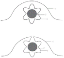
本实施例中,对患者上颌牙列的第一前磨牙进行了拔除;In this embodiment, the first premolars of the patient's maxillary dentition were extracted;
如图2所示,针对本实施例患者的一种力导控三系统口腔正畸矫治器,包括上颌牙套本体1,以及设置于上颌牙套本体1腭侧面的控制轴芯2;As shown in Figure 2, a force-guided and controlled three-system orthodontic appliance for the patient of this embodiment includes a
所述上颌牙套本体1覆盖上颌牙列,并由弹性透明材料制成,使矫治器隐形;The
所述控制轴芯2与上颌牙套本体1之间为一体式,在上颌牙套本体1腭侧面设置有中空的引导渠道作为导隧,以及用于设置引导渠道的腭侧嵴结构4;所述控制轴芯2设置于导隧内;The
所述腭侧嵴结构4设置于上颌牙套本体1覆盖上颌后牙段两侧牙齿腭侧上,以及设置于上颌牙套本体1沿上颌牙列近远中方向延伸以覆盖双侧第一前磨牙拔牙缺隙的延伸部分上;The
所述导隧只包括上颌牙列两侧的后牙段导隧3-2,其横截面形状为六角星型;且所述后牙段导隧3-2的内壁上具有齿状的内壁结构,该波浪状的内壁结构与控制轴芯2之间具有摩擦力且使得控制轴芯在后牙段导隧3-2内的径向上不具有位移自由度;所述控制轴芯2在后牙段导隧3-2内的轴向上具有位移自由度;The guide tunnel only includes the posterior segment guide tunnel 3-2 on both sides of the maxillary dentition, and its cross-sectional shape is a hexagonal star; and the inner wall of the posterior segment guide tunnel 3-2 has a tooth-shaped inner wall structure , there is friction between the wavy inner wall structure and the
所述后牙段导隧3-2的内壁有附加层,所述附加层为采用化学或物理方法处理形成高度抛光、粗糙度低的薄层结构,可使后牙段导隧3-2内壁表面与控制轴芯外表面之间的摩擦力降低;The inner wall of the posterior segment guide tunnel 3-2 has an additional layer, and the additional layer is formed by chemical or physical treatment to form a highly polished, low-roughness thin layer structure, which can make the inner wall of the posterior segment guide tunnel 3-2 Reduced friction between the surface and the outer surface of the control shaft;
所述控制轴芯2为连续的长条状轴丝结构,与上颌后牙段两侧牙齿牙弓形态一致,采用不锈钢丝材料制成;所述控制轴芯2的横截面形状为圆形;The
本实施例中一种力导控三系统口腔正畸矫治器,适合于关闭后牙拔牙间隙、同时排齐前牙解除前牙拥挤的病例。该矫治器在前牙段和后牙段具有不同的弹性模量,形成不同的三维向控制模式,其提供的力学系统可满足前牙段、后牙段不同牙移动方式的生物力学需求。该矫治器在前牙段仅有施力牙套结构,在三维向均具有较大回弹性和较大自由度,适合排齐前牙;在后牙段的垂直向控制效能增强而在近远中向形成较大自由度,可在关闭后牙拔牙间隙的同时有效防止后牙倾斜、控制牙合曲线。本实施例一种力导控三系统口腔正畸矫治器,可显著提高治疗中的可控性,提高预设路径牙移动的实现率,减少冠根往复移动,避免牙周组织或牙根损伤,保障医疗安全的同时缩短疗程,提高治疗效率,提高矫治效能。In this embodiment, an orthodontic appliance with three systems of force guidance and control is suitable for closing the tooth extraction gap of the back teeth and aligning the front teeth at the same time to relieve the crowding of the front teeth. The appliance has different elastic modulus in the anterior segment and the posterior segment, forming different three-dimensional control modes, and the mechanical system provided by it can meet the biomechanical requirements of different tooth movement modes in the anterior segment and the posterior segment. The appliance only has a force-applying brace structure in the anterior segment, which has greater resilience and greater freedom in the three-dimensional direction, and is suitable for aligning the anterior teeth; It forms a large degree of freedom, which can effectively prevent the posterior teeth from tilting and control the occlusal curve while closing the posterior tooth extraction gap. This embodiment is a force-guided three-system orthodontic appliance, which can significantly improve the controllability during treatment, increase the realization rate of tooth movement in the preset path, reduce the reciprocating movement of crown and root, and avoid periodontal tissue or tooth root damage. While ensuring medical safety, the course of treatment is shortened, the treatment efficiency is improved, and the effectiveness of correction is improved.
实施例3Example 3
本实施例中,对患者上颌牙列的第二前磨牙进行了拔除;In this embodiment, the second premolars of the patient's maxillary dentition were extracted;
如图3和图4所示,针对本实施例患者的一种力导控三系统口腔正畸矫治器,包括上颌牙套本体1,以及设置于上颌牙套本体腭侧面的控制轴芯2;As shown in Figure 3 and Figure 4, a force-guided three-system orthodontic appliance for the patient in this embodiment includes a
所述上颌牙套本体1覆盖上颌牙列,并由弹性透明材料制成,使矫治器隐形;The
所述控制轴芯2与上颌牙套本体1之间为一体式,在上颌牙套本体1腭侧面设置有中空的引导隧道作为导隧3,以及用于设置引导隧道的腭侧嵴结构;所述控制轴芯2设置于导隧3内;The
所述腭侧嵴结构设置于上颌牙套本体覆盖上颌牙齿腭侧上,以及设置于上颌牙套本体沿上颌牙列近远中方向延伸以覆盖双侧第二前磨牙拔牙缺隙的延伸部分上;The palatal ridge structure is arranged on the palatal side of the maxillary braces body covering the maxillary teeth, and on the extension part of the maxillary braces body extending along the mesio-distal direction of the maxillary dentition to cover the tooth extraction gap of the bilateral second premolars;
在前牙段处,所述导隧为前牙段导隧3-1,其横截面形状为圆角矩形,所述前牙段导隧3-1应与控制轴芯形成动配合,控制轴芯2在前牙段导隧3-1内的径向上不具有位移自由度;At the anterior tooth segment, the guide tunnel is an anterior tooth segment guide tunnel 3-1, and its cross-sectional shape is a rounded rectangle. The anterior tooth segment guide tunnel 3-1 should form a dynamic fit with the control shaft core, and the control shaft The
在上颌牙套本体沿上颌牙列近远中方向延伸以覆盖双侧第二前磨牙拔牙缺隙的延伸部分处,所述导隧为延伸部导隧3-3,其横截面形状为椭圆形,以提供控制轴芯2在径向方向上的任意方位位移,且椭圆形的长轴朝向于垂直径向;定义控制轴芯2在延伸部导隧3-3内径向上的原始位置为0,所述控制轴芯2在延伸部导隧3-3内的垂直径向上可实现的最大位移距离该原始位置0处1.5mm;所述控制轴芯2在延伸部导隧3-3内的水平径向上的可实现的最大位移距离该原始位置0处0.2mm;At the extension part where the maxillary braces body extends along the mesio-distal direction of the maxillary dentition to cover the tooth extraction gap of the bilateral second premolars, the guide tunnel is the extension guide tunnel 3-3, and its cross-sectional shape is elliptical, To provide any azimuth displacement of the
在上述延伸部分处远中方向的后牙段处,所述导隧为后牙段导隧3-2,其横截面形状为六角星型;且所述后牙段导隧3-2的内壁上具有波浪状的内壁结构,该波浪状的内壁结构与控制轴芯之间具有摩擦力且使得控制轴芯在后牙段导隧3-2内的径向上不具有位移自由度;所述控制轴芯在导隧内的轴向上具有位移自由度;At the posterior tooth segment in the distal direction at the extension part, the guide tunnel is a posterior tooth segment guide tunnel 3-2, and its cross-sectional shape is a hexagonal star; and the inner wall of the posterior tooth segment guide tunnel 3-2 It has a wavy inner wall structure, which has friction between the wavy inner wall structure and the control shaft core and makes the control shaft core have no displacement freedom in the radial direction in the posterior segment guide tunnel 3-2; the control The shaft core has a degree of freedom of displacement in the axial direction of the tunnel;
所述导隧3的内壁有附加层,所述附加层为采用化学或物理方法处理形成高度抛光、粗糙度低的薄层结构,可使导隧内壁表面与控制轴芯外表面之间的摩擦力降低;The inner wall of the
所述控制轴芯2为连续的长条状轴丝结构,在前牙段处与前牙段牙弓形态一致,在第一前磨牙近中处具有第一序列弯曲设置5-1,在第二磨牙拔牙缺隙处具有第二序列弯曲设置5-2,在后牙段其余部分处与后牙段牙弓形态一致;The
所述控制轴芯2采用不锈钢丝材料制成;所述控制轴芯2的横截面形状为圆角矩形;The
本实施例中一种力导控三系统口腔正畸矫治器,适合于关闭第二前磨牙拔牙间隙的病例。该矫治器的控制轴芯和导隧在前牙段和后牙段采用的不同形态搭配和接触方式使得矫治器在前牙段和后牙段形成不同的三维向控制模式,其提供的力学系统可满足前牙段、后牙段不同牙移动方式的生物力学需求。该矫治器在后牙段增强的垂直向控制效能和近远中向形成的较大自由度,可在关闭后牙拔牙间隙的同时有效防止后牙倾斜、控制牙合曲线;在前牙段对牙齿的垂直向移动和唇舌向转动的较强控制,可在关闭拔牙间隙时防止前牙舌倾,有效控制前牙转矩,实现前牙冠根整体移动。本实施例一种力导控三系统口腔正畸矫治器,可显著提高治疗中的可控性,提高预设路径牙移动的实现率,减少冠根往复移动,避免牙周组织或牙根损伤,保障医疗安全的同时缩短疗程,提高治疗效率,提高矫治效能。In this embodiment, an orthodontic appliance with three systems of force guidance and control is suitable for closing the tooth extraction gap of the second premolar. The different configurations and contact methods of the control shaft core and guide tunnel in the anterior segment and the posterior segment of the appliance make the appliance form different three-dimensional control modes in the anterior segment and the posterior segment, and the mechanical system provided by it It can meet the biomechanical needs of different tooth movement modes of the anterior segment and the posterior segment. The enhanced vertical control performance of the appliance in the posterior segment and the large degree of freedom formed in the mesio-distal direction can effectively prevent the posterior teeth from tilting and control the occlusal curve while closing the extraction gap of the posterior teeth; The strong control of the vertical movement of the teeth and the labial-lingual rotation can prevent the anterior teeth from lingually tilting when closing the extraction gap, effectively control the anterior tooth torque, and realize the overall movement of the anterior crown and root. This embodiment is a force-guided three-system orthodontic appliance, which can significantly improve the controllability during treatment, increase the realization rate of tooth movement in the preset path, reduce the reciprocating movement of crown and root, and avoid periodontal tissue or tooth root damage. While ensuring medical safety, the course of treatment is shortened, the treatment efficiency is improved, and the effectiveness of correction is improved.
实施例4Example 4
如图5和图6所示,本实施例一种力导控三系统口腔正畸矫治器,包括上颌牙套本体1,以及设置于上颌牙套本体1腭侧面的控制轴芯2;As shown in Fig. 5 and Fig. 6, this embodiment is an orthodontic appliance with three systems of force guidance and control, including a
所述上颌牙套本体1覆盖上颌牙列,并由弹性透明材料制成,使矫治器隐形;The
所述控制轴芯2与上颌牙套本体1之间为一体式,在上颌牙套本体腭侧面设置有中空的引导隧道作为导隧3,以及用于设置引导隧道的腭侧嵴结构;所述控制轴芯2设置于导隧3内;The
所述腭侧嵴结构设置于上颌牙套本体覆盖上颌牙齿腭侧上;The palatal ridge structure is arranged on the palatal side of the maxillary brace body covering the maxillary teeth;
所述控制轴芯2为连续的长条状轴丝结构,控制轴芯2分别在尖牙与第一前磨牙间、第一前磨牙与第二前磨牙间、第二前磨牙与第一磨牙间、第一磨牙与第二磨牙间具有第二序列弯曲设置5-2,其余部分与牙弓形态一致并覆盖至整个牙列,采用不锈钢丝材料制成;所述控制轴芯2的横截面形状为圆角矩形;The
在前牙段处,所述导隧为前牙段导隧3-1,其横截面形状为圆角矩形,所述前牙段导隧3-1应与控制轴芯形成动配合,控制轴芯2在前牙段导隧3-1内的径向上不具有位移自由度;At the anterior tooth segment, the guide tunnel is an anterior tooth segment guide tunnel 3-1, and its cross-sectional shape is a rounded rectangle. The anterior tooth segment guide tunnel 3-1 should form a dynamic fit with the control shaft core, and the control shaft The
在除第二序列弯曲设置处以外的后牙段处,所述导隧为后牙段导隧3-2,其横截面形状为六角星型;且所述后牙段导隧3-2的内壁上具有波浪状的内壁结构,该波浪状的内壁结构与控制轴芯之间具有摩擦力且使得控制轴芯在导隧内的径向上不具有位移自由度;所述控制轴芯2在后牙段导隧3-2内的轴向上具有位移自由度;At the posterior segment except the place where the second sequence of bends is set, the guide tunnel is the posterior segment guide tunnel 3-2, and its cross-sectional shape is a hexagonal star; and the posterior segment guide tunnel 3-2 There is a wavy inner wall structure on the inner wall, which has friction between the wavy inner wall structure and the control shaft core and makes the control shaft core have no displacement freedom in the radial direction of the tunnel; the
在第二序列弯曲设置5-2处,所述导隧为弯曲处导隧3-4,其横截面形状为椭圆形,以提供控制轴芯2在该处径向方向上的任意方位位移,且椭圆形的长轴朝向于垂直径向;定义控制轴芯2在弯曲处导隧3-4内径向上的原始位置为0,所述控制轴芯2在弯曲处导隧3-4内的垂直径向上可实现的最大位移距离该原始位置0处1.0mm;所述控制轴芯2在弯曲处导隧3-4内的水平径向上的可实现的最大位移距离该原始位置0处0.2mm;At the second sequence of bending settings 5-2, the guide tunnel is the guide tunnel 3-4 at the bend, and its cross-sectional shape is elliptical, so as to provide any azimuth displacement of the
所述导隧3的内壁有附加层,所述附加层为采用化学或物理方法处理形成高度抛光、粗糙度低的薄层结构,可使导隧内壁表面与控制轴芯外表面之间的摩擦力降低。The inner wall of the
本实施例中一种力导控三系统口腔正畸矫治器,适合于矫治前牙开牙合或调整后牙咬合关系的病例。该矫治器的控制轴芯和导隧在前牙段和后牙段采用的不同形态搭配和接触方式使得矫治器在前牙段和后牙段形成不同的三维向控制模式,其提供的力学系统可满足前牙段、后牙段不同牙移动方式的生物力学需求,可在配合弹性牵引的同时防止前牙舌倾,有效控制前牙转矩,同时远中竖直后牙,矫正前牙开牙合,协调后牙咬合,对于矫治前牙开牙合复杂病例具有较高的矫治效能。In this embodiment, an orthodontic appliance with three systems of force guidance and control is suitable for correcting the cases where the anterior teeth are open occlusal or the occlusal relationship of the posterior teeth is adjusted. The different configurations and contact methods of the control shaft core and guide tunnel in the anterior segment and the posterior segment of the appliance make the appliance form different three-dimensional control modes in the anterior segment and the posterior segment, and the mechanical system provided by it It can meet the biomechanical requirements of different tooth movement modes of the anterior and posterior segments, and can prevent the anterior tongue from tilting while cooperating with elastic traction, effectively control the torque of the anterior teeth, and at the same time straighten the posterior teeth distally, correcting the anterior tooth gap Occlusion, coordinate the occlusion of the posterior teeth, and has a high orthodontic effect for the complex cases of open occlusion of the anterior teeth.
Claims (10)
Priority Applications (2)
| Application Number | Priority Date | Filing Date | Title |
|---|---|---|---|
| CN202210842618.7A CN115252180B (en) | 2022-07-18 | 2022-07-18 | Force-guided three-system orthodontic appliance |
| CN202410093032.4A CN118217034A (en) | 2022-07-18 | 2022-07-18 | Force-guided orthodontic appliance based on axial movement of shaft and shaft |
Applications Claiming Priority (1)
| Application Number | Priority Date | Filing Date | Title |
|---|---|---|---|
| CN202210842618.7A CN115252180B (en) | 2022-07-18 | 2022-07-18 | Force-guided three-system orthodontic appliance |
Related Child Applications (1)
| Application Number | Title | Priority Date | Filing Date |
|---|---|---|---|
| CN202410093032.4A Division CN118217034A (en) | 2022-07-18 | 2022-07-18 | Force-guided orthodontic appliance based on axial movement of shaft and shaft |
Publications (2)
| Publication Number | Publication Date |
|---|---|
| CN115252180A true CN115252180A (en) | 2022-11-01 |
| CN115252180B CN115252180B (en) | 2024-02-20 |
Family
ID=83767245
Family Applications (2)
| Application Number | Title | Priority Date | Filing Date |
|---|---|---|---|
| CN202410093032.4A Pending CN118217034A (en) | 2022-07-18 | 2022-07-18 | Force-guided orthodontic appliance based on axial movement of shaft and shaft |
| CN202210842618.7A Active CN115252180B (en) | 2022-07-18 | 2022-07-18 | Force-guided three-system orthodontic appliance |
Family Applications Before (1)
| Application Number | Title | Priority Date | Filing Date |
|---|---|---|---|
| CN202410093032.4A Pending CN118217034A (en) | 2022-07-18 | 2022-07-18 | Force-guided orthodontic appliance based on axial movement of shaft and shaft |
Country Status (1)
| Country | Link |
|---|---|
| CN (2) | CN118217034A (en) |
Cited By (1)
| Publication number | Priority date | Publication date | Assignee | Title |
|---|---|---|---|---|
| CN116421343A (en) * | 2023-03-17 | 2023-07-14 | 北京爱普力思健康科技有限公司 | An adjustable oral appliance |
Citations (25)
| Publication number | Priority date | Publication date | Assignee | Title |
|---|---|---|---|---|
| US20020192617A1 (en) * | 2000-04-25 | 2002-12-19 | Align Technology, Inc. | Embedded features and methods of a dental appliance |
| US20030198912A1 (en) * | 2002-04-23 | 2003-10-23 | James Mah | Thin, polymeric orthodontic appliance with headgear channels |
| US20030205234A1 (en) * | 2002-05-06 | 2003-11-06 | Laura Bardach | Therapeutic and protective dental device useful as an intra-oral delivery system |
| JP2005007028A (en) * | 2003-06-20 | 2005-01-13 | Aso International:Kk | Dental retention device |
| JP2006167426A (en) * | 2004-11-17 | 2006-06-29 | Tomoaki Ogawa | Stretchable/contractive metal wire along teeth row arch for orthodontics |
| JP2008126009A (en) * | 2006-11-27 | 2008-06-05 | Matsushita Electric Works Ltd | Dentition correcting mouthpiece and its manufacturing method |
| CN201370637Y (en) * | 2009-01-16 | 2009-12-30 | 西安市恒惠科技有限公司 | Strengthened macromolecule orthodontic braces |
| US20110033814A1 (en) * | 2009-08-04 | 2011-02-10 | Wool Arthur L | Trisectional Arch Wire |
| CN201743789U (en) * | 2010-03-10 | 2011-02-16 | 尹信子 | Movable tooth rectifier |
| CN102113917A (en) * | 2010-03-10 | 2011-07-06 | 千吉文 | Movable tooth corrector and manufacture method |
| US20110311937A1 (en) * | 2008-08-06 | 2011-12-22 | Ortho-Pro-Teknica Limited | Orthodontic Space Closing Appliances |
| CN104287846A (en) * | 2014-10-13 | 2015-01-21 | 肖家良 | Tooth gap closure device |
| TW201507704A (en) * | 2013-04-05 | 2015-03-01 | Benjamin Cassalia | Orthodontic wire alignment system and method |
| KR101551608B1 (en) * | 2015-05-21 | 2015-09-08 | 이화여자대학교 산학협력단 | Wire for orthodontic treatment and device for orthodontic treatment having the same and method for orthodontic treatment thereof |
| US20150257856A1 (en) * | 2014-03-13 | 2015-09-17 | Martin G. Martz | Tooth-positioning appliance for closing spaces |
| WO2016071508A1 (en) * | 2014-11-07 | 2016-05-12 | Ortho Caps Gmbh | Method for producing a prestressed tooth repositioning device |
| WO2016179540A1 (en) * | 2015-05-06 | 2016-11-10 | Synagile Corporation | Pharmaceutical suspensions containing drug particles, devices for their administration, and methods of their use |
| CN110623759A (en) * | 2018-06-21 | 2019-12-31 | 洪澄祥 | removable orthodontic device |
| CN210095946U (en) * | 2019-05-23 | 2020-02-21 | 四川大学 | Multifunctional invisible appliance |
| CN111904630A (en) * | 2020-09-04 | 2020-11-10 | 杭州美齐科技有限公司 | Inward-retracting device of sleeve type bracket-free invisible appliance |
| CN213588537U (en) * | 2020-07-17 | 2021-07-02 | 熊国平 | Composite device for strengthening molar anchorage in bracket-free invisible orthodontic technology |
| CN113331972A (en) * | 2020-03-01 | 2021-09-03 | 吕涛 | Orthodontic self-locking bracket with open auxiliary groove |
| CN114052953A (en) * | 2021-11-22 | 2022-02-18 | 四川大学 | Orthodontic composite appliance, processed semi-finished product and processing method thereof |
| CN114081648A (en) * | 2021-11-22 | 2022-02-25 | 四川大学 | Orthodontic composite appliance, semi-finished product and processing method |
| CN114343889A (en) * | 2022-02-14 | 2022-04-15 | 成都医得康科技有限公司 | Orthodontic device and manufacturing method thereof |
-
2022
- 2022-07-18 CN CN202410093032.4A patent/CN118217034A/en active Pending
- 2022-07-18 CN CN202210842618.7A patent/CN115252180B/en active Active
Patent Citations (25)
| Publication number | Priority date | Publication date | Assignee | Title |
|---|---|---|---|---|
| US20020192617A1 (en) * | 2000-04-25 | 2002-12-19 | Align Technology, Inc. | Embedded features and methods of a dental appliance |
| US20030198912A1 (en) * | 2002-04-23 | 2003-10-23 | James Mah | Thin, polymeric orthodontic appliance with headgear channels |
| US20030205234A1 (en) * | 2002-05-06 | 2003-11-06 | Laura Bardach | Therapeutic and protective dental device useful as an intra-oral delivery system |
| JP2005007028A (en) * | 2003-06-20 | 2005-01-13 | Aso International:Kk | Dental retention device |
| JP2006167426A (en) * | 2004-11-17 | 2006-06-29 | Tomoaki Ogawa | Stretchable/contractive metal wire along teeth row arch for orthodontics |
| JP2008126009A (en) * | 2006-11-27 | 2008-06-05 | Matsushita Electric Works Ltd | Dentition correcting mouthpiece and its manufacturing method |
| US20110311937A1 (en) * | 2008-08-06 | 2011-12-22 | Ortho-Pro-Teknica Limited | Orthodontic Space Closing Appliances |
| CN201370637Y (en) * | 2009-01-16 | 2009-12-30 | 西安市恒惠科技有限公司 | Strengthened macromolecule orthodontic braces |
| US20110033814A1 (en) * | 2009-08-04 | 2011-02-10 | Wool Arthur L | Trisectional Arch Wire |
| CN201743789U (en) * | 2010-03-10 | 2011-02-16 | 尹信子 | Movable tooth rectifier |
| CN102113917A (en) * | 2010-03-10 | 2011-07-06 | 千吉文 | Movable tooth corrector and manufacture method |
| TW201507704A (en) * | 2013-04-05 | 2015-03-01 | Benjamin Cassalia | Orthodontic wire alignment system and method |
| US20150257856A1 (en) * | 2014-03-13 | 2015-09-17 | Martin G. Martz | Tooth-positioning appliance for closing spaces |
| CN104287846A (en) * | 2014-10-13 | 2015-01-21 | 肖家良 | Tooth gap closure device |
| WO2016071508A1 (en) * | 2014-11-07 | 2016-05-12 | Ortho Caps Gmbh | Method for producing a prestressed tooth repositioning device |
| WO2016179540A1 (en) * | 2015-05-06 | 2016-11-10 | Synagile Corporation | Pharmaceutical suspensions containing drug particles, devices for their administration, and methods of their use |
| KR101551608B1 (en) * | 2015-05-21 | 2015-09-08 | 이화여자대학교 산학협력단 | Wire for orthodontic treatment and device for orthodontic treatment having the same and method for orthodontic treatment thereof |
| CN110623759A (en) * | 2018-06-21 | 2019-12-31 | 洪澄祥 | removable orthodontic device |
| CN210095946U (en) * | 2019-05-23 | 2020-02-21 | 四川大学 | Multifunctional invisible appliance |
| CN113331972A (en) * | 2020-03-01 | 2021-09-03 | 吕涛 | Orthodontic self-locking bracket with open auxiliary groove |
| CN213588537U (en) * | 2020-07-17 | 2021-07-02 | 熊国平 | Composite device for strengthening molar anchorage in bracket-free invisible orthodontic technology |
| CN111904630A (en) * | 2020-09-04 | 2020-11-10 | 杭州美齐科技有限公司 | Inward-retracting device of sleeve type bracket-free invisible appliance |
| CN114052953A (en) * | 2021-11-22 | 2022-02-18 | 四川大学 | Orthodontic composite appliance, processed semi-finished product and processing method thereof |
| CN114081648A (en) * | 2021-11-22 | 2022-02-25 | 四川大学 | Orthodontic composite appliance, semi-finished product and processing method |
| CN114343889A (en) * | 2022-02-14 | 2022-04-15 | 成都医得康科技有限公司 | Orthodontic device and manufacturing method thereof |
Non-Patent Citations (2)
| Title |
|---|
| RUI SHU: "Comparison of arch width, alveolar width and buccolingual inclination of teeth between Class II division 1 malocclusion and Class I occlusion", 《THE ANGLE ORTHODONTIST》, vol. 83, no. 2, pages 246 - 252 * |
| 左丽娅: "隐形矫治与传统直丝弓固定矫治技术在不同年龄段中的应用研究", 《实用医院临床杂志》, vol. 17, no. 05, pages 133 - 135 * |
Cited By (1)
| Publication number | Priority date | Publication date | Assignee | Title |
|---|---|---|---|---|
| CN116421343A (en) * | 2023-03-17 | 2023-07-14 | 北京爱普力思健康科技有限公司 | An adjustable oral appliance |
Also Published As
| Publication number | Publication date |
|---|---|
| CN115252180B (en) | 2024-02-20 |
| CN118217034A (en) | 2024-06-21 |
Similar Documents
| Publication | Publication Date | Title |
|---|---|---|
| CN110013332B (en) | Invisible appliance for cat-shaped auxiliary bow | |
| CN110063801B (en) | Invisible appliance | |
| CN211583589U (en) | Dental appliance for adjusting relation between upper jaw position and lower jaw position and tooth correction system | |
| CN111588490A (en) | Shell-shaped tooth appliance, design method of dental appliance system and manufacturing method of dental appliance system | |
| CN211750177U (en) | Dental appliances, dental appliances, orthodontic kits and orthodontic systems | |
| CN210612259U (en) | an invisible appliance | |
| CN110063802A (en) | Mandibular deviation invisible orthotic device | |
| TWM612021U (en) | Dental treatment instrument, dental appliance kits and dental treatment appliances | |
| WO2022036926A1 (en) | Shell-shaped dental appliance, design method therefor and preparation method therefor, dental appliance set and system | |
| CN205411356U (en) | Traction spring for orthodontic traction for impacted teeth | |
| CN115252180B (en) | Force-guided three-system orthodontic appliance | |
| US20220313395A1 (en) | Dental orthodontic appliance and design method and manufacturing method thereof | |
| CN217938416U (en) | Shell-shaped dental appliance and tooth correction system | |
| CN217244883U (en) | Dual-purpose bracket combining straight wire bow and differential force | |
| EP4331529B1 (en) | Shell-shaped dental instrument and shell-shaped dental appliance set | |
| CN210095952U (en) | Invisible cat-shaped auxiliary arch appliance | |
| CN211460605U (en) | Vertical auxiliary spring for mandibular impacted molar | |
| CN219680806U (en) | Dental orthodontic device | |
| CN215019359U (en) | Orthotic system | |
| JP3251207U (en) | Shell-shaped dental appliance and orthodontic treatment system | |
| Canut | Clinical management of the mandibular molars | |
| CN221904115U (en) | Dental instrument for adjusting upper and lower jaw position relation | |
| CN223640855U (en) | Clear aligners with multi-curved structure | |
| CN114848183B (en) | Posterior tooth implantation nail supporting type anterior tooth depression auxiliary device, stress application method and application | |
| CN220938191U (en) | Tooth appliance and appliance kit thereof |
Legal Events
| Date | Code | Title | Description |
|---|---|---|---|
| PB01 | Publication | ||
| PB01 | Publication | ||
| SE01 | Entry into force of request for substantive examination | ||
| SE01 | Entry into force of request for substantive examination | ||
| GR01 | Patent grant | ||
| GR01 | Patent grant |