CN115243652A - Ear insert - Google Patents
Ear insert Download PDFInfo
- Publication number
- CN115243652A CN115243652A CN202180022230.6A CN202180022230A CN115243652A CN 115243652 A CN115243652 A CN 115243652A CN 202180022230 A CN202180022230 A CN 202180022230A CN 115243652 A CN115243652 A CN 115243652A
- Authority
- CN
- China
- Prior art keywords
- open end
- ear
- ear insert
- insert
- funnel
- Prior art date
- Legal status (The legal status is an assumption and is not a legal conclusion. Google has not performed a legal analysis and makes no representation as to the accuracy of the status listed.)
- Pending
Links
Images


Classifications
-
- A—HUMAN NECESSITIES
- A61—MEDICAL OR VETERINARY SCIENCE; HYGIENE
- A61F—FILTERS IMPLANTABLE INTO BLOOD VESSELS; PROSTHESES; DEVICES PROVIDING PATENCY TO, OR PREVENTING COLLAPSING OF, TUBULAR STRUCTURES OF THE BODY, e.g. STENTS; ORTHOPAEDIC, NURSING OR CONTRACEPTIVE DEVICES; FOMENTATION; TREATMENT OR PROTECTION OF EYES OR EARS; BANDAGES, DRESSINGS OR ABSORBENT PADS; FIRST-AID KITS
- A61F11/00—Methods or devices for treatment of the ears or hearing sense; Non-electric hearing aids; Methods or devices for enabling ear patients to achieve auditory perception through physiological senses other than hearing sense; Protective devices for the ears, carried on the body or in the hand
- A61F11/06—Protective devices for the ears
- A61F11/08—Protective devices for the ears internal, e.g. earplugs
-
- H—ELECTRICITY
- H04—ELECTRIC COMMUNICATION TECHNIQUE
- H04R—LOUDSPEAKERS, MICROPHONES, GRAMOPHONE PICK-UPS OR LIKE ACOUSTIC ELECTROMECHANICAL TRANSDUCERS; DEAF-AID SETS; PUBLIC ADDRESS SYSTEMS
- H04R1/00—Details of transducers, loudspeakers or microphones
- H04R1/10—Earpieces; Attachments therefor ; Earphones; Monophonic headphones
- H04R1/1016—Earpieces of the intra-aural type
-
- A—HUMAN NECESSITIES
- A61—MEDICAL OR VETERINARY SCIENCE; HYGIENE
- A61F—FILTERS IMPLANTABLE INTO BLOOD VESSELS; PROSTHESES; DEVICES PROVIDING PATENCY TO, OR PREVENTING COLLAPSING OF, TUBULAR STRUCTURES OF THE BODY, e.g. STENTS; ORTHOPAEDIC, NURSING OR CONTRACEPTIVE DEVICES; FOMENTATION; TREATMENT OR PROTECTION OF EYES OR EARS; BANDAGES, DRESSINGS OR ABSORBENT PADS; FIRST-AID KITS
- A61F11/00—Methods or devices for treatment of the ears or hearing sense; Non-electric hearing aids; Methods or devices for enabling ear patients to achieve auditory perception through physiological senses other than hearing sense; Protective devices for the ears, carried on the body or in the hand
- A61F11/06—Protective devices for the ears
- A61F11/08—Protective devices for the ears internal, e.g. earplugs
- A61F11/085—Protective devices for the ears internal, e.g. earplugs including an inner channel
-
- A—HUMAN NECESSITIES
- A61—MEDICAL OR VETERINARY SCIENCE; HYGIENE
- A61F—FILTERS IMPLANTABLE INTO BLOOD VESSELS; PROSTHESES; DEVICES PROVIDING PATENCY TO, OR PREVENTING COLLAPSING OF, TUBULAR STRUCTURES OF THE BODY, e.g. STENTS; ORTHOPAEDIC, NURSING OR CONTRACEPTIVE DEVICES; FOMENTATION; TREATMENT OR PROTECTION OF EYES OR EARS; BANDAGES, DRESSINGS OR ABSORBENT PADS; FIRST-AID KITS
- A61F11/00—Methods or devices for treatment of the ears or hearing sense; Non-electric hearing aids; Methods or devices for enabling ear patients to achieve auditory perception through physiological senses other than hearing sense; Protective devices for the ears, carried on the body or in the hand
- A61F11/30—Non-electric hearing aids, e.g. ear trumpets, sound amplifiers or ear-shells
-
- H—ELECTRICITY
- H04—ELECTRIC COMMUNICATION TECHNIQUE
- H04R—LOUDSPEAKERS, MICROPHONES, GRAMOPHONE PICK-UPS OR LIKE ACOUSTIC ELECTROMECHANICAL TRANSDUCERS; DEAF-AID SETS; PUBLIC ADDRESS SYSTEMS
- H04R25/00—Deaf-aid sets, i.e. electro-acoustic or electro-mechanical hearing aids; Electric tinnitus maskers providing an auditory perception
- H04R25/65—Housing parts, e.g. shells, tips or moulds, or their manufacture
- H04R25/652—Ear tips; Ear moulds
Landscapes
- Health & Medical Sciences (AREA)
- Engineering & Computer Science (AREA)
- Physics & Mathematics (AREA)
- Acoustics & Sound (AREA)
- Life Sciences & Earth Sciences (AREA)
- General Health & Medical Sciences (AREA)
- Otolaryngology (AREA)
- Signal Processing (AREA)
- Biophysics (AREA)
- Psychology (AREA)
- Biomedical Technology (AREA)
- Heart & Thoracic Surgery (AREA)
- Vascular Medicine (AREA)
- Animal Behavior & Ethology (AREA)
- Public Health (AREA)
- Veterinary Medicine (AREA)
- Neurosurgery (AREA)
- Manufacturing & Machinery (AREA)
- Headphones And Earphones (AREA)
- Prostheses (AREA)
Abstract
一种耳插入物(100),其具有漏斗形状的壁,该漏斗形状的壁限定在第一开放端部(104)与第二开放端部(109)之间延伸的渐缩通道,第一开放端部(104)具有大于第二开放端部(109)的直径的直径,其中漏斗形状的壁的邻近第二开放端部(109)的部分(108)使得耳插入物能够位于用户的耳道的开口内,其中第一开放端部(104)邻近用户的耳屏,并且第二开放端部(109)面向用户的鼓膜,渐缩通道的至少一部分包括声波反射区域(116),声波反射区域相对于由漏斗形状的壁的边缘在第一开放端部(104)处限定的横向平面成60°‑75°的角度,从第一开放端部处或附近的位置朝向第二开放端部延伸。
An ear insert (100) having a funnel-shaped wall defining a tapered channel extending between a first open end (104) and a second open end (109), the first The open end (104) has a diameter greater than the diameter of the second open end (109), wherein the portion (108) of the funnel-shaped wall adjacent the second open end (109) enables the ear insert to be positioned in the user's ear Within the opening of the canal, wherein the first open end (104) is adjacent to the user's tragus and the second open end (109) faces the user's tympanic membrane, at least a portion of the tapered channel includes a sound wave reflecting area (116) that reflects sound waves The area is at an angle of 60°-75° with respect to the transverse plane defined by the edge of the funnel-shaped wall at the first open end (104), from a position at or near the first open end towards the second open end extend.
Description
技术领域technical field
本发明大体上涉及一种用于插入耳朵中的耳插入物,并且更具体地涉及一种用于减少由耳道内的共振引起的声音失真的耳波导装置。The present invention generally relates to an ear insert for insertion into an ear, and more particularly to an ear waveguide device for reducing sound distortion caused by resonances in the ear canal.
背景技术Background technique
人耳具有三个可区分的部分,即外耳、中耳和内耳。外耳由从头部的侧部突出的被称为耳郭或耳廓的可见部分构成。中耳是被称为耳道的填充空气的窄腔,其从外耳通向内耳,耳道的内端部由鼓膜封闭,从而形成中耳与内耳之间的边界。外耳成形为形成不规则的浅漏斗,具有直接通向耳道的入口的被称为耳甲的凹陷。耳甲部分地由两个小突出部覆盖,舌状耳屏在前且对耳屏在后。The human ear has three distinguishable parts, the outer ear, the middle ear, and the inner ear. The outer ear consists of a visible part called the auricle or pinna that protrudes from the side of the head. The middle ear is an air-filled narrow cavity called the ear canal that leads from the outer ear to the inner ear, the inner end of which is closed by the tympanic membrane, forming the boundary between the middle and inner ear. The outer ear is shaped to form an irregular shallow funnel with a depression called the concha that leads directly to the entrance to the ear canal. The concha is partially covered by two small protrusions, the lingual tragus anterior and the antitragus posterior.
外耳的功能是收集声波并且经由耳道将它们引导至鼓膜。实际上,外耳用于将来自收听者附近的声波"汇集"到耳道中。耳道本质上是管,其在一端(耳甲区域)处开放,并且在另一端(鼓膜)处封闭。耳道内侧的空气充当共振体。耳道的自然共振频率是其长度的四倍(对于成人平均为约25 mm),并且因此其充当四分之一波共振器并且放大声波。因此,声波进入耳道,随着它们行进通过耳道时,声波放大,直到它们到达鼓膜并且传递到内耳。然而,包括耳甲在内的外耳的几何形状会在声波"汇集"到耳道中时对声波产生干扰,并且以非相干的声波为特征的该干扰在一些频率下以高达20 dB的增益放大,并且在鼓膜处表现为噪声失真,这可对到达内耳的声音(诸如音乐)的质量产生负面和不利的影响。The function of the outer ear is to collect sound waves and direct them to the eardrum via the ear canal. In effect, the outer ear is used to "collect" sound waves from the listener's vicinity into the ear canal. The ear canal is essentially a tube that is open at one end (the ear concha area) and closed at the other end (the eardrum). The air inside the ear canal acts as a resonator. The natural resonant frequency of the ear canal is four times its length (about 25 mm on average for an adult), and thus it acts as a quarter wave resonator and amplifies sound waves. Thus, sound waves enter the ear canal, and as they travel through the ear canal, the sound waves are amplified until they reach the eardrum and travel to the inner ear. However, the geometry of the outer ear, including the concha, interferes with the sound waves as they "pool" into the ear canal, and this interference, which is characterized by incoherent sound waves, is amplified with gains of up to 20 dB at some frequencies, And appear as noise distortion at the eardrum, which can negatively and adversely affect the quality of sound (such as music) reaching the inner ear.
而且,据记载,噪声(即干扰、打扰或减损常规功能的侵入性或不需要的声音)会引起压力,并且可对健康和生产力产生负面影响。迷走神经与副交感神经系统一起针对(除其它外)触发人类的战或逃压力反应负责。因此,结果就是。该噪声可触发战或逃反应并且引起压力。发明人已经发现,由耳甲的几何形状产生并且在耳道内放大(尤其是在约15 kHz以上的频率)的噪声失真可引起迷走神经触发战或逃压力反应。鉴于人类在他们的日常生活期间几乎不断地接收来自各种来源的声波,他们经常会在鼓膜处接收到以高达20 dB的增益放大的失真声音,并且该放大的失真声音可能会引起由迷走神经触发战或逃压力反应。因此,结果就是,普通人可能仅仅由于上文所描述的类型的噪声失真就会经常并且持续地处于提高的压力的状态中。Also, noise (ie, intrusive or unwanted sounds that interfere, disturb, or detract from normal functions) has been documented to cause stress and can negatively impact health and productivity. The vagus nerve, along with the parasympathetic nervous system, is responsible, among other things, for triggering the fight-or-flight stress response in humans. So the result is. This noise can trigger a fight-or-flight response and cause stress. The inventors have discovered that noise distortion created by the geometry of the concha and amplified within the ear canal (especially at frequencies above about 15 kHz) can cause the vagus nerve to trigger a fight or flight stress response. Given that humans receive sound waves from a variety of sources almost constantly during their daily lives, they often receive distorted sound at the eardrum that is amplified with up to 20 dB of gain, and this amplified distorted sound may be triggered by the vagus nerve Fight or flight stress response. As a result, the average person may be constantly and continuously in a state of elevated stress simply due to noise distortions of the type described above.
于是,显然,存在对于减少在人耳道内产生和放大的噪声失真的发生而不必降低到达鼓膜的真实声波的质量或音量的期望。Thus, it is clear that there is a desire to reduce the occurrence of noise distortion generated and amplified within the human ear canal without necessarily reducing the quality or volume of the real sound waves reaching the eardrum.
发明内容SUMMARY OF THE INVENTION
根据本发明的第一方面,提供了一种耳插入物,其具有大体上漏斗形状的壁,该壁限定在第一开放端部与第二开放端部之间延伸的渐缩通道,第一开放端部具有大于第二开放端部的直径或宽度的直径或宽度,其中漏斗形状的壁的紧邻第二开放端部的部分构造成使得耳插入物能够位于用户的耳道的开口内以供使用,其中第一开放端部邻近用户的耳屏,并且第二开放端部面向用户的鼓膜,渐缩通道的至少一部分包括声波反射区域,该声波反射区域相对于由漏斗形状的壁的边缘在第一开放端部处限定的横向平面成60°与75°之间的角度,从第一开放端部处或附近的位置朝向第二开放端部延伸。According to a first aspect of the present invention, there is provided an ear insert having a generally funnel-shaped wall defining a tapered channel extending between a first open end and a second open end, the first The open end has a diameter or width that is greater than the diameter or width of the second open end, wherein the portion of the funnel-shaped wall immediately adjacent the second open end is configured such that the ear insert can be positioned within the opening of the user's ear canal for Use wherein the first open end is adjacent to the user's tragus and the second open end faces the user's tympanic membrane, at least a portion of the tapered channel includes a sound wave reflective area that is located at a distance relative to the edge of the funnel-shaped wall. The transverse plane defined at the first open end is angled between 60° and 75°, extending from a position at or near the first open end towards the second open end.
在示例性实施例中,声波反射区域相对于由漏斗形状的壁的边缘在第一开放端部处限定的横向平面成65°与70°之间并且可选62°与63°之间的角度,从第一开放端部处或附近的位置朝向第二开放端部延伸。In an exemplary embodiment, the acoustic reflection area is at an angle of between 65° and 70° and optionally between 62° and 63° with respect to a transverse plane defined by the edge of the funnel-shaped wall at the first open end , extending from a location at or near the first open end toward the second open end.
有益地,并且根据特定示例性实施例,耳插入物可构造成装配到入耳式耳机的耳塞上或耳塞上方。在示例性实施例中,耳插入物可在第二开放端部处成形和构造成接收和保持弹性末端。Beneficially, and according to certain exemplary embodiments, the ear insert may be configured to fit over or over the ear tip of an in-ear headphone. In an exemplary embodiment, the ear insert may be shaped and configured at the second open end to receive and retain the elastic tip.
可选地,声波反射区域可包括基本平坦的表面。Optionally, the acoustic reflection region may comprise a substantially flat surface.
在一个实施例中,漏斗形状的壁的紧邻第二开放端部的部分可包括大体上管状部分,其具有相对于由漏斗形状的壁的边缘在第一开放端部处限定的横向平面成一定角度延伸的纵向轴线,第二开放端部位于管状部分的远侧端部处。有益地,大体上管状部分的纵向轴线可相对于由漏斗形状的壁的边缘在第一开放端部处限定的横向平面成40°与50°之间(例如大致45°)的角度延伸。In one embodiment, the portion of the funnel-shaped wall proximate the second open end may comprise a generally tubular portion having an orientation relative to a transverse plane defined by the edge of the funnel-shaped wall at the first open end An angularly extending longitudinal axis with a second open end at the distal end of the tubular portion. Beneficially, the longitudinal axis of the generally tubular portion may extend at an angle between 40° and 50° (eg approximately 45°) relative to a transverse plane defined by the edges of the funnel-shaped wall at the first open end.
有益地,管状部分可构造成插入到耳道中以供使用,其中第二开放端部面向用户的鼓膜,并且第一开放端部大体上面向用户的向后部。因此,管状部分的外径可在5 mm与8mm之间,并且第二开放端部的直径可在2 mm与5 mm之间。Beneficially, the tubular portion may be configured for insertion into the ear canal for use with the second open end facing the tympanic membrane of the user and the first open end facing generally rearward of the user. Thus, the outer diameter of the tubular portion may be between 5 mm and 8 mm, and the diameter of the second open end may be between 2 mm and 5 mm.
在示例性实施例中,漏斗形状的壁的外部轮廓可包括从邻近第一开放端部的边缘延伸到邻近第二开放端部的边缘的倒圆的凸出区域、以及在第一开放端部与第二开放端部之间的在管状部分的近侧端部处的相对的凹入区域。在此情况下,在使用中时,凹入区域限定耳插入物的前部,并且直径向相对的凸出表面限定插入物的后部,并且漏斗形状的壁的总长度可构造成使得在使用中,在管状部分部分地插入用户的耳道中的情况下,耳插入物的后部处的第一开放端部的边缘位于邻近用户的耳屏的内表面。因此,有益地,漏斗形状的壁的总长度可在7 mm与17 mm之间,并且可选地对于普通成人在10 mm与12 mm之间。In an exemplary embodiment, the outer contour of the funnel-shaped wall may include a rounded convex region extending from an edge adjacent the first open end to an edge adjacent the second open end, and at the first open end An opposing recessed area at the proximal end of the tubular portion between the second open end. In this case, in use, the concave area defines the front of the ear insert and the diametrically opposite convex surface defines the rear of the insert, and the overall length of the funnel-shaped walls can be configured such that in use In the case where the tubular portion is partially inserted into the user's ear canal, the edge of the first open end at the rear of the ear insert is located adjacent to the inner surface of the user's tragus. Thus, the overall length of the funnel-shaped walls may advantageously be between 7 mm and 17 mm, and optionally between 10 mm and 12 mm for the average adult.
在优选实施例中,第一开放端部的长度或直径可为第二开放端部的长度或直径的至少两倍。In preferred embodiments, the length or diameter of the first open end may be at least twice the length or diameter of the second open end.
在示例性实施例中,第二开放端部可为大体上椭圆形的。在此情况下,第一开放端部的长度可在9.5 mm与18 mm之间,并且第一开放端部的宽度可在7 mm与13 mm之间。In an exemplary embodiment, the second open end may be generally elliptical. In this case, the length of the first open end may be between 9.5 mm and 18 mm, and the width of the first open end may be between 7 mm and 13 mm.
在第一示例性实施例中,耳插入物可由可弹性变形材料一体地模制成。在第二示例性实施例中,至少声波反射区域可由刚性材料形成。例如,耳插入物可包括由刚性材料形成并且限定渐缩通道的内部部件、以及由刚性或可弹性变形材料形成的外部套筒。备选地,耳插入物可由诸如塑料、木材或金属的刚性材料一体地形成。In a first exemplary embodiment, the ear insert may be integrally molded from an elastically deformable material. In the second exemplary embodiment, at least the acoustic wave reflection region may be formed of a rigid material. For example, an ear insert may include an inner member formed of a rigid material and defining a tapered channel, and an outer sleeve formed of a rigid or elastically deformable material. Alternatively, the ear insert may be integrally formed from a rigid material such as plastic, wood or metal.
在其它示例性实施例中,渐缩通道可在其较窄端部处与同轴管连通,渐缩通道的内表面和管的内表面是围绕公共纵向轴线旋转的表面,并且管的外表面限定至少一个周向脊或凹槽,其中管的内表面具有至少2.5 mm的直径,管的外表面具有不超过10 mm的直径,并且插入物的总长度不超过17 mm。In other exemplary embodiments, the tapered channel may communicate with a coaxial tube at its narrower end, the inner surface of the tapered channel and the inner surface of the tube are surfaces that rotate about a common longitudinal axis, and the outer surface of the tube At least one circumferential ridge or groove is defined, wherein the inner surface of the tube has a diameter of at least 2.5 mm, the outer surface of the tube has a diameter of no more than 10 mm, and the overall length of the insert does not exceed 17 mm.
在此情况下,渐缩通道至少沿其长度的一部分可为锥形的,并且相对的锥形表面之间的角度可在30°与60°之间,并且更优选在40°与50°之间。In this case, the tapered channel may be tapered at least along a portion of its length, and the angle between the opposing tapered surfaces may be between 30° and 60°, and more preferably between 40° and 50° between.
可选地,渐缩通道可具有弯曲的纵向形状。例如,渐缩通道可为外扩的,使得随着直径减小,对内表面的切线与纵向轴线之间的角度也减小。Alternatively, the tapered channel may have a curved longitudinal shape. For example, the tapered channel may be flared such that as the diameter decreases, the angle between the tangent to the inner surface and the longitudinal axis also decreases.
在一些示例性实施例中,渐缩通道的窄端部可具有弯曲的纵向形状,使得管的内表面与弯曲的纵向形状在它们相遇的地方相切。In some exemplary embodiments, the narrow end of the tapered channel may have a curved longitudinal shape such that the inner surface of the tube is tangent to the curved longitudinal shape where they meet.
管的内表面可具有至少2.2 mm但小于6.0 mm的直径,并且管的外表面可具有不超过8 mm的直径。The inner surface of the tube may have a diameter of at least 2.2 mm but less than 6.0 mm, and the outer surface of the tube may have a diameter of no more than 8 mm.
插入物的总长度可在7 mm与16.5 mm之间,并且管的长度可在插入物的总长度的25%与50%之间。The overall length of the insert may be between 7 mm and 16.5 mm, and the length of the tube may be between 25% and 50% of the overall length of the insert.
可选地,在渐缩通道的较宽端部处,外径可在9 mm与18 mm之间。Optionally, at the wider end of the tapered channel, the outer diameter may be between 9 mm and 18 mm.
在一些优选实施例中,耳插入物的尺寸可使得当承载弹性末端的管插入到耳道中时,在使用中,外端部不会突出超过耳屏。In some preferred embodiments, the ear insert is sized such that when the tube carrying the elastic tip is inserted into the ear canal, in use, the outer end does not protrude beyond the tragus.
附图说明Description of drawings
现在将仅通过示例的方式并且参照附图来描述本发明的实施例,在附图中。Embodiments of the invention will now be described, by way of example only, with reference to the accompanying drawings, in which.
具体实施方式Detailed ways
诸如上、下、左、右、顺时针、逆时针、前部、后部和其它类似形容词的方向描述词语是为了清楚而使用,并且指的是如附图中所图示的本发明的定向,然而对于对本领域中的技术人员将清楚,本发明可能并不总是如所图示的那样定向,并且本发明不旨在在这方面受到限制。Directional descriptors such as up, down, left, right, clockwise, counterclockwise, front, rear and other similar adjectives are used for clarity and refer to the orientation of the invention as illustrated in the drawings , however, it will be apparent to those skilled in the art that the present invention may not always be oriented as illustrated and that the present invention is not intended to be limited in this respect.
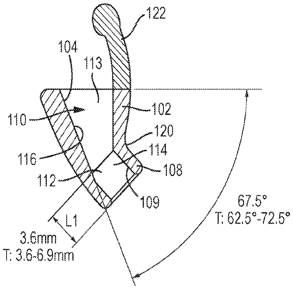
参看附图的图1A至1G,图示了根据本发明的第一示例性实施例的耳插入物100。耳插入物100包括单件模制的硅树脂或其它可模制并且可弹性变形的塑料材料。插入物包括具有两个一体式部分的大体上倒圆的外部轮廓。第一管状部分102具有大体上椭圆形的横截面和开放的第一端部104。第一管状部分102在开放的第一端部104处的外横向宽度OW(图1C)在7 mm至13 mm的范围内,例如对于普通成人为10 mm,并且外横向长度OL(图1C)在9.8mm至18 mm的范围内,例如对于普通成人为13 mm。第一管状部分的尺寸沿其长度逐渐减小,并且在相对的第二端部106处,外径OD1(图1F)可在6 mm至9 mm的范围内,例如对于普通成人为7 mm。一体的第二管状部分108从第一管状部分102的第二端部106延伸,使得其纵向轴线与第一管状部分102的纵向轴线成35°-70°,例如45°角。插入物的外部轮廓在一侧("后部")上是凸出的并且相对平缓地倒圆,以适应第一管状部分102与第二管状部分108之间的角度,并且在另一侧("前部")上,该角度由第一管状部分与第二管状部分之间的倒圆但相对尖锐的凹入"拐角"容纳。在其远侧端部109处开放的第二管状部分108具有大体上圆形横截面,并且具有在5 mm至8 mm范围内的外径OD2(图1B),例如对于普通成人为6 mm,并且具有在3.6 mm至6.9 mm的范围内的长度L1(图2),例如对于普通成人为3.6 mm。将认识到,可因要求而在给定的范围内改变各种尺寸以适合较小或较大的耳朵,并且甚至是儿童的尺码。Referring to Figures 1A to 1G of the drawings, an
另外参看附图的图2,第一一体部分102和第二一体部分108一起限定了通过其中的连续通道110,该通道本身由两个部分构成:限定为通过第一管状部分102的第一通道部分112、以及限定为通过第二管状部分108的第二通道部分114。第一通道部分沿"前部"和"侧部"由第一管状部分102的椭圆形状的倒圆轮廓限定。然而,第一管状部分102的"后"壁比其余的壁更厚,从而提供基本平坦的"后部"通道部分112,从而提供平坦表面116。如附图的图2中所示出的,当插入物100处于"直立"位置时,其中第一开放端部104的横向平面是水平的,第一通道部分113的平坦表面116朝向第二通道部分114以大于45°的锐角延伸,并且第一通道部分113的直径或宽度从开放端部104到与由第二管状部分108限定的第二通道部分114的接合部减小。平坦表面116相对于由第一开放端部104的横向平面限定的水平面的角度可在62.5至72.5°的范围内,例如对于普通成人为67.5°。Referring additionally to FIG. 2 of the drawings, the first
如上文所描述并且由图2最佳地图示的,第二管状部分108相对于第一管状部分102的成角度的构造通过平缓倒圆的外壁容纳在插入物的"后部"和"侧部"处,该外壁从第一开放端部104弯曲到由第二管状部分108限定的远侧第二开放端部109。如上文所陈述的,第二管状部分108的长度L1(图2)在3.6 mm至6.9 mm的范围内,例如对于普通成人为3.6mm。远侧开放端部109的直径ID(图1F)可在2.2 mm至5 mm的范围内,例如对于普通成人为4mm。将认识到,尽管第二管状部分108的开放端部109在该示例性实施例中图示为大体上圆形,但其可具有备选的形状和构造。例如,在其它示例性实施例中,其大体上可为椭圆形的或"狭缝状的",并且本发明不一定旨在在这方面受到限制。第二管状部分108的"前"壁和"侧"壁的厚度沿到由凹入的倒圆"拐角"120限定的第一管状部分102与第二管状部分108之间的接合部的长度基本是恒定的。然而,尽管第二通道部分114的直径从远侧开放端部109沿第二管状部分108的长度的一部分基本恒定,但其朝向第一管状部分102与第二管状部分108之间的接合部沿短部分向内渐缩(借助于加厚第二管状部分108的后壁),使得第二通道部分114的内后壁的该短部分形成限定第一通道部分113的"后"壁的平坦表面116的延伸部。As described above and best illustrated by FIG. 2, the angled configuration of the second
可提供伸长的凸片122,伸长的凸片从第一管状部分102的边沿在其开放端部104处延伸,以便于将装置插入到用户的耳朵中以及从用户的耳朵中取出装置。
在上文所描述的示例性实施例中,耳插入物100由诸如硅树脂的弹性柔性材料一体地模制成。然而,在备选示例性实施例中,插入物100可具有两部分的构造。在此情况下,该装置可包括:金属(例如不锈钢或钛)插入物,其提供限定第一通道部分113和第二通道部分114(即,包括平坦表面116的通道);以及外部套筒,其由弹性柔性材料(诸如泡沫或硅树脂)形成,限定了弯曲的外部轮廓以使装置能够舒适地装配在用户的耳朵内。因此,当平坦(反射)表面116由刚性材料形成时,噪声失真上的减少可进一步加强。In the exemplary embodiment described above, the
在使用中,耳插入物100在耳道的开放端部(邻近耳甲区域)处插入到用户的耳朵中,使得第二管状部分延伸到耳道中(其中远侧开放端部109面向耳道的另一端处的鼓膜),并且第一管状部分102的倒圆的"后"表面搁置在耳屏处或就在耳屏后,其中第一开放端部104面向后。将认识到,在该示例中,第二管状部分108的外径(OD2)设计为与普通成人的耳道(外耳道)入口的直径大致相同。插入物100的总长度(不包括凸片122)大致等于普通成人的外耳道的平均长度,其中外耳道包括从耳屏延伸到中耳的耳道。结果,插入物100可完全插入到外耳道中,其中第一管状部分102的外边缘抵靠耳屏的后(内)表面搁置,并且第二管状部分108短距离地延伸到耳道中,其中远侧开放端部109面向鼓膜。In use, the
如上文所描述的,至少插入物100的外壁有益地由柔软的可弹性变形材料(诸如硅树脂)形成,使得其可充分压缩以插入到耳朵中,并且然后一旦已插入就释放回其原始形式,以贴合地装配在耳朵内。在图1A至图1G和图2中所图示的示例中,插入物(包括异型内部通道)由诸如硅树脂的可模制材料一体地形成。然而,并且如上文所陈述的,在备选实施例中,装置可包括限定包括平坦表面116的异型内部通道的内部部件,以及围绕内部部件的外部套筒部件。在此情况下,内部部件可由诸如塑料或金属(例如不锈钢或钛)的刚性材料形成,并且套筒部件可由诸如硅树脂的可弹性变形材料形成,以在使用中提供舒适的贴合装配。As described above, at least the outer wall of
由第二管状部分108的纵向轴线限定的角度与限定在围绕第一开放端部104的边沿之间的直径向平面成大致45°,并且设在第一通道部分113的"后"内表面(和第二通道部分114的小部分)处的平坦表面116相对于第二管状部分108的纵向轴线的角度为大致22.5°。发明人已经发现,这些相对角度,并且尤其是平坦反射表面116相对于插入物的第一开放端部104和第二开放端部109的角度,可在具有平均耳朵尺寸的成人中提供最佳结果。而且,并且如先前所陈述的,所有尺寸,尤其是管状部分102、108的外部尺寸,都可调整(具体是在所设置的公差内)以适应例如儿童的耳朵尺寸,或具有较大或较小的外耳道的成人。The angle defined by the longitudinal axis of the second
一旦装置就位,其中位于耳道中的第二管状部分108的远侧开放端部109面向鼓膜,并且第一管状部分102的"上"边缘抵靠耳屏的后(内)表面搁置,其中第一开放端部104面向后,其有效地用于最小化或甚至消除耳甲对进入耳朵的声波的影响。该装置仍将声波"汇集"到耳道中,因为其具有宽度超过第二远侧端部109直径的两倍的第一开放端部104的管状形状和构造。成角度的平坦表面116用于使到达外耳道的声波在它们到达鼓膜之前反射的次数最小化。鉴于正是这些反射在声波中产生了非相干性,并且正是该非相干性表现出然后在耳道内放大的失真或"噪声",明显该装置在使用中用于减少到达鼓膜的声波中的失真。在没有该装置的情况下,来自收听者附近的声波会到达耳甲区域中的外耳道,该区域限定可相对于耳道的纵向轴线(通向鼓膜)成高达90°的角度的表面。因此,到达外耳道的声波必须以最多90°改变方向来到达鼓膜。然而,声波,尤其是那些超过约1.5 kHz的不是高度衍射的声波,只可通过在耳甲区域内的重复反射来以此方式"改变方向",直到它们定向成进入耳道。外耳道的结构及其凹槽和脊使得这些声波在进入耳道之前可反射多次。这些反射导致进入耳道的主要非相干的声波,并且此类非相干的声波(表现出显著的失真或"噪声")在它们到达鼓膜之前在耳道内放大。相比之下,本发明的耳插入物用于将更相干的声波以显著更少的反射"汇集"到耳道中,由此将失真(或"噪声")减少多达8%或更多。如果用户在例如通过如上文所描述的耳机听音乐时而佩戴该插入物,则收听者所听到的音乐的质量和清晰度会显著改善。而且,并且最令人惊讶的是,如果用户在进行他们正常的日常生活时佩戴该插入物,则由该插入物提供的噪声失真上的显著减少用于减少由迷走神经触发战或逃的压力反应的情况。因此,通过佩戴本发明的插入物(优选在每只耳朵中一个),用户体验到平静效果,因为在他们的正常日常生活期间减轻了压力。Once the device is in place with the distal
参看附图的图3A至3E,示意性地图示了通道内的平坦(反射)表面116的效果。在图3A中,进入的声波130以相对于由插入物100的第一开放端部104的平面限定的"水平面"成72.5°的角度进入第一通道部分113。如所图示的,入射声波130碰撞装置100的第一管状部分102内的反射表面116,并且所产生的反射声波140朝向鼓膜被引导直线地通过第二开口109。因此,只有单个相干声波进入耳道。类似地,并且如图3B至3E中所示出的,分别以70°、67.5°、65°和62.5°的角度入射的声波130由反射表面116朝向鼓膜反射而直线地通过插入物100中的第二开口109。Referring to Figures 3A to 3E of the drawings, the effect of a flat (reflective)
在上文所描述的实施例中,耳插入物是用于改善由用户听到的声音的质量和清晰度的独立装置,用户可能佩戴或未佩戴耳机。在备选实施例中,本发明的插入物可构造成装配在一副无线耳机的一体式耳塞(ear bud)中的每一个上,或作为具有管输出件的任何现有耳机的末端。在又一个示例性实施例中,如下文将更详细地描述的,根据本发明的插入物可构造成装配有可弹性变形末端,诸如在常规耳塞和入耳式耳机中使用的末端。In the embodiments described above, the ear insert is a stand-alone device for improving the quality and intelligibility of sound heard by the user, who may or may not be wearing headphones. In alternative embodiments, the insert of the present invention may be configured to fit over each of the integral ear buds of a pair of wireless earphones, or as the end of any existing earphone with a tube output. In yet another exemplary embodiment, as will be described in more detail below, inserts according to the present invention may be configured to be fitted with elastically deformable tips, such as those used in conventional earplugs and in-ear headphones.
因此,参看附图的图4至图6,根据第二示例性实施例的耳插入物10可描述为大体上为漏斗形状,因为其由管状壁12构成,管状壁在一端处限定渐缩通道14,并且在另一端处限定管16,渐缩通道14和管16具有公共纵向轴线17(如图6中所示出的)。渐缩通道的窄端部具有与管16相同的内径。在该示例中,渐缩通道是锥形的,并且相对的锥形表面之间的角度是45°Thus, with reference to Figures 4-6 of the drawings, the
管状壁12具有基本均一的厚度,因此限定锥形的渐缩通道14的壁12的外表面也是锥形的,但是管16的外表面限定邻近管16的开放端部的周向脊18,并且邻近于管16与渐缩通道14之间的过渡限定了周向台阶20,因此在脊18与台阶20之间存在周向凹部19。在该示例中,管16的内径为3.5 mm,并且脊18的外径为5.5 mm。在该示例中,耳插入物10的总长度为12 mm。The
将认识到,本发明的耳插入物可在一些细节上与该示例性实施例的耳插入物10不同。例如,渐缩通道的内表面与管的内表面之间可能存在逐渐过渡,而不是突然过渡;实际上,渐缩通道可沿其长度具有纵向弯曲的形状,例如,像喇叭口一样外扩,而不是锥形。It will be appreciated that the ear insert of the present invention may differ in some details from the
现在参看附图的图7和8,在使用之前,如通常与耳机一起使用的那样,用户将为耳插入物10提供管状并且有弹性的硅树脂或泡沫末端。具有倒圆的端部的末端22在图7中以虚线示出,而更短并且更少倒圆的末端23在图8中以虚线示出。在每种情况下,末端22、23是管状的,并且末端22、23的一端紧紧地装配在管16上方,与周向脊18和19接合,并且其中末端22或23的端部邻接台阶20。因此,末端22或23牢固地附接到耳插入物10。Referring now to Figures 7 and 8 of the drawings, prior to use, the user will provide the
然后,用户将耳插入物10和末端22或23插入到他们的耳朵中,其中末端22或23和管16装配到用户的耳道中,并且渐缩通道14的开放端部的边缘位于耳屏后。渐缩通道14的壁可用于将用户耳朵的耳屏向一侧弯曲。典型地,用户会插入两个此类耳插入物,每只耳朵中一个。耳插入物10的总长度使得插入之后,耳插入物的外端部与耳屏的外表面大致齐平,因此耳插入物10不会从耳朵突出,并且不显眼。The user then inserts
再次,耳插入物10的形状和构造用于将来自用户附近的声波"汇集"到耳道中并且朝向鼓膜。渐缩通道14的倾斜度使得入射声波在到达鼓膜之前可能仅反射一次,因此减少失真并且改善了由用户听到的声音的清晰度和质量。如果用户使用耳机,将认识到,来自耳机的平行于纵向轴线17入射的任何声音都可沿无阻碍的直线路径进入到耳道的内部部分中。这具有增强声音清晰度的效果。Again, the
从前述描述中对于本领域的技术人员将显而易见的是,可在不脱离由所附权利要求限定的本发明的范围的情况下对所描述的实施例作出修改和变化。From the foregoing description it will be apparent to those skilled in the art that modifications and variations can be made in the described embodiments without departing from the scope of the invention as defined by the appended claims.
Claims (35)
Applications Claiming Priority (3)
| Application Number | Priority Date | Filing Date | Title |
|---|---|---|---|
| GB2004011.9A GB2593205A (en) | 2020-03-19 | 2020-03-19 | An ear insert |
| GB2004011.9 | 2020-03-19 | ||
| PCT/GB2021/050676 WO2021186182A1 (en) | 2020-03-19 | 2021-03-18 | An ear insert |
Publications (1)
| Publication Number | Publication Date |
|---|---|
| CN115243652A true CN115243652A (en) | 2022-10-25 |
Family
ID=70546736
Family Applications (1)
| Application Number | Title | Priority Date | Filing Date |
|---|---|---|---|
| CN202180022230.6A Pending CN115243652A (en) | 2020-03-19 | 2021-03-18 | Ear insert |
Country Status (7)
| Country | Link |
|---|---|
| US (1) | US12137313B2 (en) |
| EP (1) | EP4120979B1 (en) |
| CN (1) | CN115243652A (en) |
| AU (1) | AU2021238937A1 (en) |
| CA (1) | CA3169269A1 (en) |
| GB (1) | GB2593205A (en) |
| WO (1) | WO2021186182A1 (en) |
Families Citing this family (5)
| Publication number | Priority date | Publication date | Assignee | Title |
|---|---|---|---|---|
| USD1058539S1 (en) * | 2020-03-23 | 2025-01-21 | Flare Audio Technologies Limited | Earphone |
| US20220313423A1 (en) * | 2021-04-02 | 2022-10-06 | United States Government As Represented By The Department Of Veterans Affairs | Ear Stent And Methods Of Using Same |
| GB2614033A (en) * | 2021-10-14 | 2023-06-28 | Flare Audio Tech Limited | Ear insert |
| WO2025093849A1 (en) | 2023-11-03 | 2025-05-08 | Flare Audio Technologies Limited | Ear insert |
| WO2025093847A1 (en) | 2023-11-03 | 2025-05-08 | Flare Audio Technologies Limited | Ear insert |
Citations (9)
| Publication number | Priority date | Publication date | Assignee | Title |
|---|---|---|---|---|
| GB190116423A (en) * | 1901-08-15 | 1902-01-16 | Samuel Giles Payn | Improvements in Magnetic Devices to Restore and Aid the Hearing. |
| US20080152163A1 (en) * | 2006-12-21 | 2008-06-26 | David Mulvey | Earbud coupling |
| CN102596131A (en) * | 2009-06-03 | 2012-07-18 | 斯博瑞安听觉保护有限责任公司 | Non-roll foam eartip |
| US20140138179A1 (en) * | 2008-01-07 | 2014-05-22 | Burton Technologies, Llc | Earbuds and in-ear adapter for earbuds |
| US20140369545A1 (en) * | 2011-12-26 | 2014-12-18 | D&M Holdings Inc. | Headphone device |
| CN205336492U (en) * | 2016-01-21 | 2016-06-22 | 唐永均 | Headphone |
| US20170065457A1 (en) * | 2015-09-08 | 2017-03-09 | Moritaka OGURA | Simplified hearing aid |
| KR20190003082U (en) * | 2018-06-05 | 2019-12-13 | 탐라엔씨(주) | Earplug for bidirectional noise blocking |
| CN110603814A (en) * | 2016-11-28 | 2019-12-20 | 因诺维尔医疗公司 | System, method and device for communication in a noisy environment |
Family Cites Families (1)
| Publication number | Priority date | Publication date | Assignee | Title |
|---|---|---|---|---|
| CN208598633U (en) * | 2017-08-08 | 2019-03-15 | 珠海卓力声科技有限公司 | Elbow noise reduction earplug |
-
2020
- 2020-03-19 GB GB2004011.9A patent/GB2593205A/en not_active Withdrawn
-
2021
- 2021-03-18 WO PCT/GB2021/050676 patent/WO2021186182A1/en not_active Ceased
- 2021-03-18 CA CA3169269A patent/CA3169269A1/en active Pending
- 2021-03-18 AU AU2021238937A patent/AU2021238937A1/en active Pending
- 2021-03-18 CN CN202180022230.6A patent/CN115243652A/en active Pending
- 2021-03-18 EP EP21714356.9A patent/EP4120979B1/en active Active
-
2022
- 2022-08-31 US US17/899,674 patent/US12137313B2/en active Active
Patent Citations (9)
| Publication number | Priority date | Publication date | Assignee | Title |
|---|---|---|---|---|
| GB190116423A (en) * | 1901-08-15 | 1902-01-16 | Samuel Giles Payn | Improvements in Magnetic Devices to Restore and Aid the Hearing. |
| US20080152163A1 (en) * | 2006-12-21 | 2008-06-26 | David Mulvey | Earbud coupling |
| US20140138179A1 (en) * | 2008-01-07 | 2014-05-22 | Burton Technologies, Llc | Earbuds and in-ear adapter for earbuds |
| CN102596131A (en) * | 2009-06-03 | 2012-07-18 | 斯博瑞安听觉保护有限责任公司 | Non-roll foam eartip |
| US20140369545A1 (en) * | 2011-12-26 | 2014-12-18 | D&M Holdings Inc. | Headphone device |
| US20170065457A1 (en) * | 2015-09-08 | 2017-03-09 | Moritaka OGURA | Simplified hearing aid |
| CN205336492U (en) * | 2016-01-21 | 2016-06-22 | 唐永均 | Headphone |
| CN110603814A (en) * | 2016-11-28 | 2019-12-20 | 因诺维尔医疗公司 | System, method and device for communication in a noisy environment |
| KR20190003082U (en) * | 2018-06-05 | 2019-12-13 | 탐라엔씨(주) | Earplug for bidirectional noise blocking |
Also Published As
| Publication number | Publication date |
|---|---|
| GB202004011D0 (en) | 2020-05-06 |
| AU2021238937A1 (en) | 2022-09-22 |
| EP4120979C0 (en) | 2025-05-07 |
| EP4120979B1 (en) | 2025-05-07 |
| US12137313B2 (en) | 2024-11-05 |
| EP4120979A1 (en) | 2023-01-25 |
| US20220417638A1 (en) | 2022-12-29 |
| WO2021186182A1 (en) | 2021-09-23 |
| CA3169269A1 (en) | 2021-09-23 |
| GB2593205A (en) | 2021-09-22 |
Similar Documents
| Publication | Publication Date | Title |
|---|---|---|
| CN115243652A (en) | Ear insert | |
| TWI868989B (en) | Open earphone | |
| US20220183892A1 (en) | Device for protecting the human sensory hearing system while retaining quality sound | |
| CN107548561B (en) | Earphone set | |
| CN114339511B (en) | Wireless headphones | |
| BR112017015523B1 (en) | EAR BODY, HEARING PROTECTION DEVICE AND KIT | |
| US20240251201A1 (en) | Ear insert | |
| CN105122842B (en) | behind-the-ear hearing aids | |
| GB2635220A (en) | Ear insert | |
| GB2635215A (en) | Ear insert | |
| KR20050112325A (en) | Ear insert of earphone | |
| KR100496907B1 (en) | Back sound reduction type headphone | |
| US20190201243A1 (en) | Vented Sound Attenuation Earplug System | |
| WO2025093849A1 (en) | Ear insert | |
| GB2639521A (en) | Ear insert | |
| WO2025093847A1 (en) | Ear insert | |
| WO2025030694A1 (en) | Earphone capable of being stably worn | |
| CN206596166U (en) | The structure of the earphone | |
| CN118843029A (en) | Ear plug |
Legal Events
| Date | Code | Title | Description |
|---|---|---|---|
| PB01 | Publication | ||
| PB01 | Publication | ||
| SE01 | Entry into force of request for substantive examination | ||
| SE01 | Entry into force of request for substantive examination |