CN115234115A - Spacing maintaining device - Google Patents
Spacing maintaining device Download PDFInfo
- Publication number
- CN115234115A CN115234115A CN202210430038.7A CN202210430038A CN115234115A CN 115234115 A CN115234115 A CN 115234115A CN 202210430038 A CN202210430038 A CN 202210430038A CN 115234115 A CN115234115 A CN 115234115A
- Authority
- CN
- China
- Prior art keywords
- wall
- pin
- axial direction
- base
- stop
- Prior art date
- Legal status (The legal status is an assumption and is not a legal conclusion. Google has not performed a legal analysis and makes no representation as to the accuracy of the status listed.)
- Pending
Links
- 230000002093 peripheral effect Effects 0.000 claims abstract description 23
- 125000006850 spacer group Chemical group 0.000 claims description 59
- 238000007789 sealing Methods 0.000 claims description 42
- 238000001746 injection moulding Methods 0.000 claims description 8
- 238000003780 insertion Methods 0.000 claims description 7
- 230000037431 insertion Effects 0.000 claims description 7
- 230000007704 transition Effects 0.000 claims description 5
- 238000006073 displacement reaction Methods 0.000 claims description 3
- 238000002360 preparation method Methods 0.000 claims 9
- 108091006146 Channels Proteins 0.000 description 39
- 238000004519 manufacturing process Methods 0.000 description 7
- XLYOFNOQVPJJNP-UHFFFAOYSA-N water Substances O XLYOFNOQVPJJNP-UHFFFAOYSA-N 0.000 description 5
- 238000013461 design Methods 0.000 description 4
- 238000012423 maintenance Methods 0.000 description 3
- 230000007480 spreading Effects 0.000 description 3
- 238000005260 corrosion Methods 0.000 description 2
- 230000007797 corrosion Effects 0.000 description 2
- 230000000149 penetrating effect Effects 0.000 description 2
- 238000006748 scratching Methods 0.000 description 2
- 230000002393 scratching effect Effects 0.000 description 2
- 102000010637 Aquaporins Human genes 0.000 description 1
- 108010063290 Aquaporins Proteins 0.000 description 1
- 230000008901 benefit Effects 0.000 description 1
- 230000008878 coupling Effects 0.000 description 1
- 238000010168 coupling process Methods 0.000 description 1
- 238000005859 coupling reaction Methods 0.000 description 1
- 230000001419 dependent effect Effects 0.000 description 1
- 230000000694 effects Effects 0.000 description 1
- 230000010354 integration Effects 0.000 description 1
- 230000003993 interaction Effects 0.000 description 1
- 239000000463 material Substances 0.000 description 1
- 239000000155 melt Substances 0.000 description 1
- 238000000034 method Methods 0.000 description 1
- 230000004048 modification Effects 0.000 description 1
- 238000012986 modification Methods 0.000 description 1
Images


Classifications
-
- E—FIXED CONSTRUCTIONS
- E05—LOCKS; KEYS; WINDOW OR DOOR FITTINGS; SAFES
- E05F—DEVICES FOR MOVING WINGS INTO OPEN OR CLOSED POSITION; CHECKS FOR WINGS; WING FITTINGS NOT OTHERWISE PROVIDED FOR, CONCERNED WITH THE FUNCTIONING OF THE WING
- E05F5/00—Braking devices, e.g. checks; Stops; Buffers
- E05F5/02—Braking devices, e.g. checks; Stops; Buffers specially for preventing the slamming of swinging wings during final closing movement, e.g. jamb stops
- E05F5/022—Braking devices, e.g. checks; Stops; Buffers specially for preventing the slamming of swinging wings during final closing movement, e.g. jamb stops specially adapted for vehicles, e.g. for hoods or trunks
- E05F5/025—Braking devices, e.g. checks; Stops; Buffers specially for preventing the slamming of swinging wings during final closing movement, e.g. jamb stops specially adapted for vehicles, e.g. for hoods or trunks specially adapted for vehicle doors
-
- B—PERFORMING OPERATIONS; TRANSPORTING
- B62—LAND VEHICLES FOR TRAVELLING OTHERWISE THAN ON RAILS
- B62D—MOTOR VEHICLES; TRAILERS
- B62D25/00—Superstructure or monocoque structure sub-units; Parts or details thereof not otherwise provided for
- B62D25/08—Front or rear portions
- B62D25/10—Bonnets or lids, e.g. for trucks, tractors, busses, work vehicles
- B62D25/12—Parts or details thereof
-
- E—FIXED CONSTRUCTIONS
- E05—LOCKS; KEYS; WINDOW OR DOOR FITTINGS; SAFES
- E05Y—INDEXING SCHEME ASSOCIATED WITH SUBCLASSES E05D AND E05F, RELATING TO CONSTRUCTION ELEMENTS, ELECTRIC CONTROL, POWER SUPPLY, POWER SIGNAL OR TRANSMISSION, USER INTERFACES, MOUNTING OR COUPLING, DETAILS, ACCESSORIES, AUXILIARY OPERATIONS NOT OTHERWISE PROVIDED FOR, APPLICATION THEREOF
- E05Y2201/00—Constructional elements; Accessories therefor
- E05Y2201/20—Brakes; Disengaging means; Holders; Stops; Valves; Accessories therefor
- E05Y2201/224—Stops
-
- E—FIXED CONSTRUCTIONS
- E05—LOCKS; KEYS; WINDOW OR DOOR FITTINGS; SAFES
- E05Y—INDEXING SCHEME ASSOCIATED WITH SUBCLASSES E05D AND E05F, RELATING TO CONSTRUCTION ELEMENTS, ELECTRIC CONTROL, POWER SUPPLY, POWER SIGNAL OR TRANSMISSION, USER INTERFACES, MOUNTING OR COUPLING, DETAILS, ACCESSORIES, AUXILIARY OPERATIONS NOT OTHERWISE PROVIDED FOR, APPLICATION THEREOF
- E05Y2600/00—Mounting or coupling arrangements for elements provided for in this subclass
- E05Y2600/10—Adjustable
- E05Y2600/12—Adjustable by manual operation
-
- E—FIXED CONSTRUCTIONS
- E05—LOCKS; KEYS; WINDOW OR DOOR FITTINGS; SAFES
- E05Y—INDEXING SCHEME ASSOCIATED WITH SUBCLASSES E05D AND E05F, RELATING TO CONSTRUCTION ELEMENTS, ELECTRIC CONTROL, POWER SUPPLY, POWER SIGNAL OR TRANSMISSION, USER INTERFACES, MOUNTING OR COUPLING, DETAILS, ACCESSORIES, AUXILIARY OPERATIONS NOT OTHERWISE PROVIDED FOR, APPLICATION THEREOF
- E05Y2600/00—Mounting or coupling arrangements for elements provided for in this subclass
- E05Y2600/10—Adjustable
- E05Y2600/30—Adjustment motion
- E05Y2600/31—Linear motion
- E05Y2600/314—Vertical motion
-
- E—FIXED CONSTRUCTIONS
- E05—LOCKS; KEYS; WINDOW OR DOOR FITTINGS; SAFES
- E05Y—INDEXING SCHEME ASSOCIATED WITH SUBCLASSES E05D AND E05F, RELATING TO CONSTRUCTION ELEMENTS, ELECTRIC CONTROL, POWER SUPPLY, POWER SIGNAL OR TRANSMISSION, USER INTERFACES, MOUNTING OR COUPLING, DETAILS, ACCESSORIES, AUXILIARY OPERATIONS NOT OTHERWISE PROVIDED FOR, APPLICATION THEREOF
- E05Y2900/00—Application of doors, windows, wings or fittings thereof
- E05Y2900/50—Application of doors, windows, wings or fittings thereof for vehicles
- E05Y2900/53—Type of wing
- E05Y2900/536—Hoods
-
- E—FIXED CONSTRUCTIONS
- E05—LOCKS; KEYS; WINDOW OR DOOR FITTINGS; SAFES
- E05Y—INDEXING SCHEME ASSOCIATED WITH SUBCLASSES E05D AND E05F, RELATING TO CONSTRUCTION ELEMENTS, ELECTRIC CONTROL, POWER SUPPLY, POWER SIGNAL OR TRANSMISSION, USER INTERFACES, MOUNTING OR COUPLING, DETAILS, ACCESSORIES, AUXILIARY OPERATIONS NOT OTHERWISE PROVIDED FOR, APPLICATION THEREOF
- E05Y2900/00—Application of doors, windows, wings or fittings thereof
- E05Y2900/50—Application of doors, windows, wings or fittings thereof for vehicles
- E05Y2900/53—Type of wing
- E05Y2900/546—Tailboards, tailgates or sideboards opening upwards
-
- E—FIXED CONSTRUCTIONS
- E05—LOCKS; KEYS; WINDOW OR DOOR FITTINGS; SAFES
- E05Y—INDEXING SCHEME ASSOCIATED WITH SUBCLASSES E05D AND E05F, RELATING TO CONSTRUCTION ELEMENTS, ELECTRIC CONTROL, POWER SUPPLY, POWER SIGNAL OR TRANSMISSION, USER INTERFACES, MOUNTING OR COUPLING, DETAILS, ACCESSORIES, AUXILIARY OPERATIONS NOT OTHERWISE PROVIDED FOR, APPLICATION THEREOF
- E05Y2900/00—Application of doors, windows, wings or fittings thereof
- E05Y2900/50—Application of doors, windows, wings or fittings thereof for vehicles
- E05Y2900/53—Type of wing
- E05Y2900/548—Trunk lids
Landscapes
- Engineering & Computer Science (AREA)
- Chemical & Material Sciences (AREA)
- Combustion & Propulsion (AREA)
- Transportation (AREA)
- Mechanical Engineering (AREA)
- Snaps, Bayonet Connections, Set Pins, And Snap Rings (AREA)
- Moulds For Moulding Plastics Or The Like (AREA)
- Sealing Devices (AREA)
- Closures For Containers (AREA)
Abstract
A pitch maintaining device. It includes: a tubular base element having a peripheral wall and a flange-like bottom wall portion, wherein an inner wall portion of the peripheral wall delimits the receiving space and an outer wall portion of the peripheral wall is integrally formed with an external thread, and wherein a pin channel is designed in the bottom wall portion, wherein a fastening device is provided on the side of the bottom wall opposite the peripheral wall for connecting the spacing device with the carrier member. Further, the space maintaining device includes: a pin element arranged in the receiving space for actuating the fastening device, the pin element pin extending through the pin channel; and a bowl-shaped stop cap with internal threads, the internal threads being in engagement with the external threads of the base member; and a stopper wall extending orthogonally to the axial direction, wherein the stopper cap and the fastening device are arranged substantially flush with each other in the axial direction.
Description
The invention relates to a spacer device for arranging two components at a distance from each other or at a distance from each other.
DE 40 11 186 discloses a stop for the hood of a motor vehicle. The stop is formed by a base having a left-handed internal thread that receives a threaded bushing. The pin has a rounded head which is fastened by means of a split bolt. The bolt has a right-hand thread with a tip that urges the split body to expand, thereby engaging this body into the seat. This unique feature can allow for axial adjustment after the stop has been installed on the hood.
EP-a-611868 describes an adjustable three-piece stop having: a carrier; an axially adjustable stop element arranged in the cavity of the carrier; and a rotatable securing element operable to lock the stop element in the preferred position.
WO 2018/063847 A1 gives an adjustable stop element. Here, the stop element and the fastening element are arranged offset by 90 ° with respect to one another.
The object of the present invention is to further develop the spacer known from the prior art and/or to provide an alternative to the spacer known from the prior art.
It is another object of the present invention to provide a shipping fixture for a spacing device.
Furthermore, it is an object of the invention to provide a spacer device, the components of which are fixed relative to one another in an output position or in a transport-fixing position.
One or more of these objects are achieved by the features of the independent patent claim 1. Advantageous embodiments are given in the respective dependent claims.
According to the present invention, a space maintaining apparatus is provided. The space maintaining apparatus includes:
a base element having a tubular circumferential wall and a bottom wall, wherein an inner wall section of the circumferential wall delimits the receiving space, and wherein a pin channel is designed in the bottom wall, wherein fastening means are provided on the side of the bottom wall opposite the circumferential wall for connecting the distance-retaining device with the carrier member;
a pin element arranged in the receiving space for actuating the fastening means, the pin element extending through the pin channel; and
a stopper member, wherein the stopper member and the peripheral wall of the base member are rotatably connected to each other by a screw connection.
The bottom wall may be designed flange-like.
A first thread, preferably an external thread, may be integrally formed on a wall portion, preferably an outer wall portion, of the peripheral wall.
The stop element may have a second thread, preferably an internal thread, which is in engagement with the first thread, preferably an external thread, of the base element.
Wherein the retaining element has a retaining wall which preferably extends orthogonally to the axial direction, wherein the retaining element and the fastening device are arranged substantially flush with one another in the axial direction.
The threaded connection can be designed such that the peripheral wall of the base element has a first thread and the stop element has a second thread. The first thread can be designed as an external thread on an outer wall portion of the circumferential wall of the base element and the second thread can be designed as an internal thread on an inner wall portion of the stop element. The reverse can also be achieved in that the first thread can be designed as an internal thread on an inner wall section of the circumferential wall of the base element, while the second thread can be designed as an external thread on an outer wall section of the stop element.
The stop element is preferably designed as a bowl-shaped stop cap. However, the stop element can also be designed cylindrical, tubular, rectangular or pin-shaped, wherein a stop surface extending substantially orthogonally to the axial direction is always provided.
The spacer device according to the invention has been developed in particular for use in the automotive field. Adjustable spacing means are used, for example, to damp vibrations of the component to be opened (for example, a trunk lid or a hood) and to reduce these vibrations.
The purpose of the spacer is to support a movable structural carrier member (e.g., a trunk lid or hood of a vehicle) in a position flush with a fixed structural carrier member (e.g., the body of a vehicle). The relative spacing between the two structural components may vary, for example, due to manufacturing and assembly tolerances. Therefore, there is a need for adjustable distance holders that can compensate for manufacturing and assembly tolerances between two components. According to the invention, therefore, a spacer is provided for the first time in which the locking flap and the fastening device are arranged flush with one another in the axial direction.
The stop cap constitutes an adjustable tolerance compensation element.
The spacer devices are designed for fitting into the carrier member in a fitting direction, wherein a fitting direction is understood to be a direction substantially orthogonal to a surface of the carrier member into which the respective spacer device is inserted or on which the respective spacer device is attached. The fitting direction substantially corresponds to the axial direction or extends parallel to the axial direction.
In particular, at least one and preferably two diametrically opposed positioning means can be arranged on the bottom wall, which are designed as latching elements and extend in the axial direction into the receiving space. The stopper cap may have: an outer peripheral wall having an internal thread formed integrally thereon, and a tubular inner positioning wall disposed concentrically with the outer peripheral wall. A positioning recess which is designed radially around and in correspondence with the positioning means can be arranged on the inner wall of the tubular positioning wall in order to fix the locking cap against rotation relative to the base element.
By providing at least one positioning means on the bottom wall of the base element and at least one correspondingly designed positioning recess in the retaining cap, an anti-rotation or transport-securing feature is formed which prevents the retaining cap from rotating relative to the base element or ensures that the retaining cap is arranged on the base element in a predetermined manner.
In this way, the stop cap is safely and reliably prevented from rotating relative to the base element in the home position or transport position. The desired distance from the bottom wall of the spacer to the stop wall, i.e. the predetermined distance, can thus already be set in advance after the spacer has been produced. When the spacer is supplied as an assembly to a customer, the desired distance is safely and reliably maintained.
Thus, with correspondingly precise manufacturing tolerances, fine adjustment of the stop cap is no longer necessary. The fastening device is then sufficient to connect the spacer device to the carrier element, in particular a motor vehicle. Each spacer then has a predetermined desired, predetermined distance between the bottom wall and the stop wall. Thus, only one assembly step is required, in which the fastening device is fixed by means of the pin element and the spacer is connected to the carrier component.
The positioning device can be of substantially L-shaped design, wherein a long limb of the positioning device extends in the axial direction and an orthogonally extending short limb of the positioning device is designed at its free end in the manner of a latching element for engaging into a corresponding positioning recess.
The distance between the stop wall and the bottom wall can be finely adjusted by a rotational movement of the stop cap about the longitudinal axis of the spacer.
The relative position between the retaining cap and the base element is thus fixed in a positionally fixed manner by the positioning means and the positioning recess.
The fastening device may be formed by expansion wings (Spreifflugel) arranged radially around the pin channel, which expansion wings are expandable by means of the pin element. Preferably three to five and preferably four expansion wings can be provided. The expansion wings can form a substantially rectangular and preferably square anti-rotation portion in the region of the bottom wall. Latching elements which extend outward in the radial direction can preferably be integrally formed at the spreading wings in order to hold the distance-keeping device in the carrier component in the preassembly position.
The expansion wings are expanded by displacing the pin element in the axial direction in the direction of the expansion wings and the spacing device is fixed in the channel of the carrier member.
In this way, the spacer can be easily and safely mounted in the carrier component.
The expansion wing coupling pin element forms an expansion rivet.
Since the expansion wings form a substantially rectangular and preferably square anti-rotation portion in the region of the bottom wall, the spacer is held in the carrier component against rotation, so that the spacer or its base element is held in the carrier component against rotation when the stop cap is adjusted or when the stop cap is rotated.
By providing the expansion wings with latching elements which extend outward in the radial direction, it is possible to fix the distance-maintaining device in a preassembly position in which the distance-maintaining device is held together with the carrier component by the latching elements in the carrier component. In this case, the advantage is also obtained that the distance holders remain held in the carrier element in the event of an employee forgetting to activate the fastening device.
The pin element may comprise a head portion and a shank portion, wherein an actuating face extending orthogonally to the axial direction is provided at the head portion for displacing the pin element in the axial direction.
The actuating surface can be acted upon in the axial direction by means of a tool in such a way that the pin element can be displaced in the axial direction.
Furthermore, a recess, preferably a (through) recess, extending orthogonally to the axial direction can be designed in the head part for releasing the fastening device by means of a tool.
By providing a recess for removing the fastening device, the spacer can be removed by the following steps: the locking cap is unscrewed, exposing the receiving space. The tool is then inserted laterally into the recess and a force is applied to the pin element in the axial direction in such a way that the pin element is disengaged from the expansion wings of the fastening device and the spacer can be removed.
A radially encircling, disk-shaped sealing portion can be provided in the transition region from the head portion to the shank portion.
Further, a substantially cylindrical guide portion may be provided adjacent the sealing portion to guide the pin element in the pin channel.
By means of the guide portion, on the one hand a safe and reliable guidance of the pin element upon displacement in the axial direction is ensured. On the other hand, away from the pin channel.
Adjacent to the fixing part, a transport fixing part can be provided for fixing the transport position or the home position of the pin element.
Furthermore, a tapered insertion portion may be provided adjacent to the transport securing portion.
In the case of the initial assembly of the spacing device, the insertion portion of the pin element facilitates the insertion of the pin element into the pin channel. Furthermore, the insertion portion facilitates the expansion of the expansion wings of the fastening device.
In the center of the stop face, an actuation channel can be designed for displacing the pin element in the axial direction by means of a tool, wherein the actuation channel is preferably delimited by an annular portion extending into the receiving space, and wherein preferably the head portion of the pin element is arranged locally in the actuation channel in the home position, and the actuation channel preferably forms the drive.
The drive may preferably be designed as an internal hexagonal drive, whereby the tool by means of which the force is exerted in the axial direction on the actuating face of the pin element is preferably an internal hexagonal wrench.
Furthermore, the actuating opening can be used with the aid of an internal hexagonal drive in order to rotate the stop cap about the longitudinal axis and thus to fine-tune or subsequently adjust the spacer in terms of the distance of the bottom wall from the stop face.
Alternatively, the drive can also be designed on the peripheral wall of the stop element or of the stop cap (for example as an outer hexagon).
A sealing ring can be arranged on the bottom wall in the receiving space in a manner radially surrounding the pin channel, the sealing part of the pin element in the assembly position sealingly abutting against the sealing ring; and/or wherein a sealing lip extending in the axial direction is integrally formed radially around on the side of the base wall opposite the peripheral wall, wherein the sealing ring and the sealing lip are formed from a soft component and are preferably produced together with the base element by means of a 2-component injection molding process.
By providing a sealing ring, the pin channel is sealed in the event of interaction with the disk-shaped sealing portion of the pin element.
By providing the sealing lip, the bottom wall of the spacer is formed in a splash-proof or possibly even waterproof manner with respect to the surface of the carrier member to which the spacer is connected. In this way, water, for example rainwater or molten water, is prevented from penetrating and the carrier member is protected against corrosion.
By means of a corresponding 2-component injection molding process, the base element can be manufactured in a simple manner.
Furthermore, the sealing ring can be connected to the bottom wall, preferably by means of a tubular guide element which delimits the pin channel, in such a way that the guide portion of the pin element is guided during the transition from the transport position to the assembly position. By means of the tubular guide element, the pin element is guided safely and reliably when displaced in the axial direction.
Since the guide element is arranged in the region of the pin channel, water is prevented from flowing thereby towards the sealing ring or towards the pin channel. In this way, water penetrating into the spacer can be safely and reliably drained, thereby preventing corrosion.
The transport-securing part of the pin element can have securing plates which are arranged radially around and at an equidistant spacing from one another and extend in the axial direction, wherein the securing plates are arranged between the expansion wings of the fastening device in the transport position and secure the pin element against displacement in the axial direction, and wherein the number of securing plates corresponds to the number of expansion wings.
The pin element is prevented by means of the securing plate from being unintentionally displaced in the axial direction relative to the base element. Furthermore, the expansion wings are secured by arranging securing plates in the area between them to prevent them from being damaged during transport or from being bent undesirably.
The region of the external thread which is flush in the axial direction may have a different pitch than the remaining external thread, so that a curved portion is formed in the external thread in order to clamp the internal thread of the retaining element with the external thread of the base element.
Conventional threads, in particular plastic threads, always have a certain tolerance or play in the axial direction. This play is avoided by means of the curved portion and the stop cap is clamped to the external thread of the base element.
At least one radial drainage opening can be provided in the peripheral wall of the base element in the region of the base wall, and/or at least three and preferably four spacer elements extending in the axial direction can be formed integrally on the locking cap in the region of the base wall radially around.
By providing a drainage opening, water that has penetrated into the receiving space via the actuation channel can be drained from the receiving space.
Since the hemispherical spacer elements are integrally formed on the bottom wall, water can flow away even in the completely screwed-together state. However, the spacer element prevents in particular the locking cap from being screwed too tightly or completely onto the base element in such a way that it rests directly on the bottom wall.
The (preferably radially circumferential) edge of the actuating channel can have a chamfer in the region of the stop wall of the stop cap.
This chamfer prevents scratching or stamping of the actuating channel on the component (e.g. hood or tailgate) in contact with the stop wall or on a corresponding stop element formed by a soft component fastened thereto.
On the side of the base wall opposite the receiving space, a recess can be formed radially around the expansion fin.
The recess prevents the expansion wing from lifting the spacing device in the fastened state from the surface of the carrier component connected to the spacing device. The recess thus improves or enables a full-surface abutment of the bottom wall of the base element with the surface of the carrier member.
Furthermore, a guide flange which extends in the axial direction into the receiving space can be integrally formed on the bottom wall.
The guide flange enables guiding and centering of the pin device and in this way prevents incorrect positioning of the pin device and tilting or skewing of the pin device when actuating the spacing device.
The components of the spacer can be produced from plastic (hard component) by means of a 1-component or multi-component injection molding process and, if necessary, partially integrally formed parts from soft component.
The spacer means is preferably connected to the carrier member in a mounting direction extending parallel to the axial direction or orthogonally to the surface of the carrier member delimiting the channel.
Further, according to the present invention, a pitch maintenance system includes: the distance-retaining device shown above and the corresponding stop element, which can be fastened to a component (in particular a hood or tailgate), are formed from a soft component.
The invention will be described in more detail below with the aid of exemplary embodiments shown in the drawings. In the drawings:
figure 1 shows an exploded perspective view of a spacer according to the invention according to a first exemplary embodiment,
figure 2 shows a side sectional view of the spacer,
fig. 3 shows a side view of the spacer device, wherein the retaining cap is completely screwed onto the base element,
fig. 4 shows a side sectional view of the spacing device, wherein the stop cap is arranged at the greatest possible distance from the bottom wall of the base element,
figure 5 shows a side sectional partial view of the spacer in the home position,
figure 6 shows a side detail view of a spacer element of the spacer device,
figure 7 shows a plan view of the spacer device from below,
figure 8 shows a side view of the spacing device,
figure 9 shows a side sectional view of the spacer device,
figure 10 shows a top view of the spacer from above,
figure 11 shows a perspective view of the pin element,
figure 12 shows a side view of the base element,
figure 13 shows a perspective view of the stop cap,
figure 14 shows a further perspective view of the stop cap,
figure 15 shows a perspective view of the base element,
figure 16 shows a further perspective view of the base element,
figure 17 shows a side sectional view of a spacer according to a second exemplary embodiment,
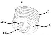
FIG. 18 shows a perspective view of the base member and the pin member, an
Fig. 19 shows a further perspective view of the base element and the pin element.
The spacer 1 according to the invention is described in more detail below (fig. 1 to 16).
The spacer 1 comprises a base element 2, a pin element 3 and a stop cap 4.
The base element 2 has a tubular peripheral wall 5 and a flange-like bottom wall 6. An inner wall portion 7 of the circumferential wall 5 delimits a receiving space 8.
An external thread 10 is integrally formed on the outer wall portion 9 of the peripheral wall 5, by means of which the base element 2 can be connected with the locking cap 4.
A pin channel 11 is designed in the bottom wall 6 of the base element 2. In the region of the receiving space 8, the pin channel 11 is delimited by a tubular guide element 12. A sealing ring 13 is integrally formed at the guide element, preferably by means of a 2-component injection molding process.
Furthermore, two positioning means 14 which are diametrically opposed to one another and extend in the axial direction are integrally formed on the bottom wall 6 in the region of the receiving space 8.
The positioning device 14 is of substantially L-shaped design, wherein the long limb 15 extends in the axial direction 16 and is connected to the bottom wall 6. The short branch 17 extends outward in the radial direction or orthogonal to the axial direction 16. At the free end of the short branch 17, a positioning element 18 is integrally formed, which is substantially semicircular in plan view.
On the side of the base wall 6 opposite the receiving space 8, an expansion wing 19 is integrally formed which extends in the axial direction radially around the pin channel 11. Preferably, four expansion wings 19 are provided, arranged radially around and equidistantly spaced apart from each other. Alternatively, three or five or more expansion wings 19 may also be provided.
At the expansion wings 19 there are preferably provided fixing elements 20 extending outwards in radial direction. In particular the expansion wings 19, but preferably also the fixing elements 20, form fastening means of the spacer device 1 for connection with a channel (not shown) of a carrier member.
In the region of the bottom wall 6, the expansion wings 19 or the fastening means 21 have a substantially rectangular and preferably square anti-rotation portion 22. The rotation of the spacer 1 is fixed by means of the rotation-prevention part 22, in particular when the locking cap 4 is actuated, that is to say rotated. Thus, the anti-rotation portion 22 forms an anti-rotation device.
On the side of the base wall 6 opposite the receiving space 8, a sealing lip 23 is integrally formed at the edge of the base wall, which sealing lip extends radially around and in the axial direction 16.
The sealing lip 23 is preferably likewise connected in one piece to the bottom wall 6 by means of a 2-component injection molding process. For manufacturing reasons, the sealing lip is connected to the sealing ring 13 via a melt channel 24.
Furthermore, a sealing lip receiving recess 25 extending inward in the radial direction may be provided at the bottom wall or at a radially surrounding edge thereof. The sealing lip receiving recess 25 facilitates the integration of the sealing lip 23 on the bottom wall 6.
For manufacturing reasons, the tubular circumferential wall 5 may be interrupted in the region of the positioning device 14 by recesses extending in the axial direction. This may be necessary due to the use of a sliding tool when manufacturing the spacer. The positioning means 14 are arranged in the region of these recesses.
The locking cap 4 is of substantially bowl-shaped design, wherein the locking cap has an internal thread 26 by means of which the locking cap 4 is connected to the base element 2.
Furthermore, the stop cap 4 has a stop wall 27 extending orthogonally to the axial direction 16.
The internal thread 26 is formed on the outer peripheral wall 28 of the stopper cap 4. An inner, likewise tubular positioning wall 29 is arranged concentrically to the outer circumferential wall 28.
Positioning recesses 31 which are radially arranged around and spaced apart from one another at equal distances and which are designed in accordance with the positioning elements 18 of the positioning device 14 are formed on the inner wall 30 of the positioning wall. The positioning recess 31 is designed substantially semicircular in cross section.
Since the positioning element 18 of the positioning device 14 is in engagement with the positioning recess 31 of the retaining cap 4, the retaining cap 4 is fixed in position against rotation about the longitudinal axis 32. By applying a predetermined force in the direction of rotation about the longitudinal axis 32, the long limbs 15 of the positioning device 14 are bent inward in the radial direction and the positioning elements 31 correspondingly jump into the subsequent positioning recesses 31.
An actuating channel 33 is provided in the approximate center of the stop wall 27 of the stop cap 4. The actuation channel 33 simultaneously has a drive 34 in such a way that it has a hexagonal shape in cross section, so that an internal hexagonal drive 34 is formed by the actuation channel 33.
A plurality of drainage openings 35 are formed in the circumferential wall 5 of the base element 2 in the region of the bottom wall 6 in a radially circumferential manner.
Four substantially hemispherical distance retaining elements 36, which extend in the axial direction 16, are integrally formed on the locking cap 4 in the region of the bottom wall 6 in a radially encircling manner.
The pin element 3 comprises a head portion 37 and a shank portion 38.
An actuating surface 39 extending orthogonally to the axial direction 16 is provided at the head portion 37 in order to displace the pin element 3 in the axial direction 16 by means of a tool.
The actuating surface 39 is arranged in the home position in the region of an annular portion 40 extending into the receiving space 8, which annular portion delimits the actuating channel 33. The annular portion 40 has a hexagonal shape in cross section and thus also forms the internal hexagonal drive 34.
Adjacent to the actuating surface 39, a through-opening 41 extending orthogonally to the axial direction 16 is formed in the head part. With unscrewing of the locking cap 4, a tool can be arranged in the through-recess 41 to displace the pin element 3 in the axial direction 16.
A radially encircling, disk-shaped sealing portion 43 is provided in the transition region 42 from the head portion 37 to the shank portion 38. In the final assembly position, the sealing portion 43 sealingly abuts the sealing ring 13 of the base element 2.
Adjacent to the sealing portion 43, a substantially cylindrical guide portion 44 is designed. The cylindrical guide portion 44 is guided in the tubular guide element 12 of the base element in the axial direction 16 and thus prevents tilting of the pin element and ensures precise guidance of the pin element in the axial direction 16.
Adjacent to the guide portion 44, a cylindrical fixing portion 45 is provided on the pin element 3. In the final assembly position, the fixing portion 45 holds or exerts a force outwardly in the radial direction on the expansion wing 19 in such a way that the spacing device 1 can be safely and reliably assembled or fastened in the channel of the carrier member.
A transport securing portion 46 is provided adjacent to the securing portion 45 to secure the pin member 3 in the home position.
The transport-securing part 46 has securing tabs 47 which extend in the axial direction and are arranged radially around and at equidistant spacing from one another. Here, four fixing pieces 47 are provided, wherein the number of fixing pieces 47 corresponds to the number of expansion wings 19. The fixing tab 47 is arranged between the expansion wings 19 of the fastening device 21 in the home position or the displaced position and fixes the pin element 3 against sliding in the axial direction 16.
Adjacent to the shipping fixture 46 is a tapered insertion portion 48.
The method for assembling the spacer according to the present invention is briefly described below.
First, the expansion wing 19 is inserted into the channel of the carrier member such that the snap-lock elements 20 engage with the corresponding edges of the channel. The spacer 1 is arranged in the channel in a rotationally fixed manner by means of a rotation-prevention portion 22.
Subsequently, the actuating face 39 of the pin element is acted upon in the axial direction 16 in such a way that the securing tab 47 is displaced in the axial direction 16 from the region between the expansion wings 19, and wherein the expansion wings 19 are bent outward in the radial direction by means of the securing section 45 of the pin element 3, and wherein the securing section 45 simultaneously secures the expansion wings 19 against inward movement in the radial direction or prevents such movement.
The sealing portion 43 of the pin element 3 then sealingly abuts the sealing ring 13 of the base element 2.
The distance or spacing between the stop wall 27, the stop cap 4 and the bottom wall 6 can be preset immediately after manufacture.
For this purpose, the stop cap 4 is preferably offset about the longitudinal axis 32 by means of a tool (for example an internal hexagonal wrench arranged in an internal hexagonal drive 34) until a desired distance or a desired spacing between the bottom wall 6 and the stop wall 27 is reached.
The bottom wall 6 is sealingly connected to the surface of the carrier member by means of a sealing lip 23.
To release the spacer 1, the locking cap 4 must only be unscrewed from the base element 2. Subsequently, a tool can be inserted laterally into the through-recess 41 of the pin element 3, which can then be displaced in the axial direction 16 with a lever movement in such a way that the fixing portion 45 is moved away from the region of the expansion wing 19.
The expansion wings 19 are thereby moved inward in the radial direction, wherein the fastening tabs 47 are then again arranged in the region between the expansion wings 19.
The inventive spacing device 1 according to a second exemplary embodiment is described in detail below (fig. 17 to 19).
The spacer 1 according to the second exemplary embodiment corresponds substantially to the spacer 1 according to the first exemplary embodiment or is a modification of this spacer 1. Unless otherwise stated, the pitch maintenance device 1 according to the second exemplary embodiment has the same technical features as the pitch maintenance device 1 according to the first exemplary embodiment. The same technical features are provided with the same reference numerals. The technical features of the two exemplary embodiments can thus be combined with each other as desired.
According to a second exemplary embodiment, the actuation channel 33 of the stop cap 4 is inclined or chamfered or provided with a chamfer 49 in the region of the stop wall 27.
The component which comes into contact with the stop wall 27 or the region of the component which comes into contact with this stop wall is protected against scratching by the chamfer 49. Due to the provision of the chamfer 49, no stamping mark (stempelabductk) to the actuation channel 33 or the drive 34 occurs on the component in contact with the stop wall 27.
On the side of the bottom wall 6 opposite the receiving space 8, a recess 50, which is approximately rectangular in top view from below or corresponds to the cross section of the spreading wing 19, is formed radially around the spreading wing 19.
The recess 50 prevents the expansion wings 19 from lifting the spacer device 1 from the surface of the carrier element in the latched or fastened state when connected to the channel of the carrier element. The recess 50 thus ensures that the bottom wall 6 completely abuts the carrier member connected thereto.
In this way, the spacer 1 can be positioned precisely on the carrier component, so that it can be fixed approximately orthogonally to the surface of the carrier component.
In the region between the two positioning means 14, two guide flanges 51 are arranged diametrically opposite one another. The guide flange is formed integrally on the bottom wall 6 and extends in the axial direction 16 into the receiving space 8. The guide flange 51 is of substantially plate-like design and has a curvature corresponding to the pin channel 11 in plan view.
The pin element 3 is guided in the axial direction 16 by guide flanges 51 diametrically opposite to each other. When the spacer 1 is used, the guide flange 51 prevents the pin device from tilting. Accordingly, the guide flange 51 forms a centering means for the pin element 3.
The inventive spacer according to the second embodiment thus corresponds substantially to the inventive spacer according to the first embodiment, wherein additionally the chamfer 49, the notch 50 and the guide flange 51 provide the described technical effect.
The base element 2, the pin element 3 and the stop cap 4 of the spacer 1 are made of a plastic material formed from a hard component and are produced by means of an injection molding process. The corresponding sealing element made of plastic is formed from a soft component and can be manufactured and molded in one operation by a 2-component injection molding process.
List of reference numerals
1. Spacing maintaining device
2. Base element
3. Pin element
4. Stop cap
5. Tubular peripheral wall
6. Bottom wall
7. Inner wall part
8. Receiving space
9. Inner wall part
10. External thread
11. Pin channel
12. Tubular guide element
13. Sealing ring
14. Positioning device
15. Long branch
16. Axial direction of the shaft
17. Short branch
18. Positioning element
19. Expansion wing
20. Latching element
21. Fastening device
22. Anti-rotation part
23. Sealing lip
24. Melt channel
25. Sealing lip receiving recess
26. Internal thread
27. Stop wall
28. Outer peripheral wall
29. Positioning wall
30. Inner wall
31. Positioning notch
32. Longitudinal axis
33. Actuating channel
34. Internal hexagonal driving part
35. Drainage opening
36. Spacing element
37. Head part
38. Handle part
39. Actuating surface
40. Annular part
41. Through recess
42. Transition region
43. Sealing part
44. Guide part
45. Fixing part
46. Transport fixing part
47. Fixing sheet
48. Insertion part
49. Chamfer angle
50. Notch (S)
51. Guide flange
Claims (10)
1. A spacing device (1) comprising:
a base element (2) having a tubular peripheral wall (5) and a base wall (6), wherein an inner wall section (7) of the peripheral wall delimits a receiving space (8), and wherein a pin channel (11) is designed in the base wall (6), wherein a fastening device (21) is provided on the side of the base wall (6) opposite the peripheral wall for connecting the distance-keeping device (1) to a carrier component; and
a pin element (3) arranged in the receiving space (8) for actuating the fastening means (21), the pin element extending through the pin channel (11); and
a stop element (4), wherein the stop element (4) and a circumferential wall of the base element (2) are rotatably connected to each other by a threaded connection.
2. Spacing device (1) according to claim 1,
it is characterized in that the preparation method is characterized in that,
an external thread (10) is integrally formed on an outer wall portion of a peripheral wall of the base member (2), and wherein
The stop element (4) has an internal thread (26) which is in engagement with the external thread (10) of the base element (2), wherein the stop element (4) has a stop wall (27) which extends orthogonally to the axial direction (16), and wherein
The stop element (4) and the fastening device (21) are arranged substantially flush with one another in the axial direction (16).
3. Spacing device (1) according to claim 1 or 2,
it is characterized in that the preparation method is characterized in that,
at least one and preferably two positioning means (14) which are diametrically opposite one another and extend in the axial direction (16) into the receiving space (8) and are designed in the manner of a latching element are arranged on the bottom wall (6), wherein
The retaining element (4) has an inner, tubular positioning wall (29), wherein a positioning recess (31) is arranged on an inner wall (30) of the tubular positioning wall (29), which is designed radially around and in accordance with the positioning device (14), in order to fix the retaining element (4) against rotation relative to the base element (2).
4. Spacing device (1) according to one of claims 1 to 3,
it is characterized in that the preparation method is characterized in that,
the fastening device (21) is formed by an expansion wing (19) arranged radially around the pin channel (11), which is expandable by means of the pin element (3), wherein preferably three to five and preferably four expansion wings (19) are provided, wherein the expansion wings (19) form a substantially rectangular anti-rotation portion (22) in the region of the bottom wall (6), and wherein latching elements (20) extending outward in the radial direction are preferably integrally formed at the expansion wings (19) in order to hold the spacing device (1) in the preassembled position in the carrier component.
5. Spacing device (1) according to one of claims 1 to 4,
it is characterized in that the preparation method is characterized in that,
the pin element (3) comprises a head portion (37) and a shank portion (38), wherein an actuating surface (39) extending orthogonally to the axial direction (16) is provided at the head portion (37) for displacing the pin element (3) in the axial direction (16); and/or wherein a recess (50) extending orthogonally to the axial direction (16) is designed in the head portion (37) for dismounting the fastening device (21) by means of a tool; and/or wherein a radially encircling, disk-shaped sealing portion (43) is provided in a transition region (42) from the head portion to the shank portion (37, 38); and/or wherein adjacent to the sealing portion (43) a substantially cylindrical guiding portion (44) is provided for guiding the pin element (3) in the pin channel (11); and/or wherein adjacent to the guide portion (44) a substantially cylindrical fixing portion (45) is provided to fix the expansion wings (19) in the expanded final assembly position; and/or wherein a transport securing portion (46) is provided adjacent to the securing portion (45) to secure the pin element (3) in the home position; and/or wherein a tapered insertion portion (48) is provided adjacent to the transport securing portion (46).
6. Spacing device (1) according to one of claims 1 to 5,
it is characterized in that the preparation method is characterized in that,
an actuation channel (33) is designed centrally on the stop surface in order to displace the pin element (3) in the axial direction (16) by means of a tool, wherein the actuation channel (33) is preferably delimited by an annular portion (40) extending into the receiving space (8), and wherein preferably a head portion (37) of the pin element (3) is arranged locally in the actuation channel (33) in the home position, and the actuation channel (33) preferably forms a drive.
7. Spacing device (1) according to one of claims 1 to 6,
it is characterized in that the preparation method is characterized in that,
a sealing ring (13) is arranged on the bottom wall (6) in the receiving space (8) in a manner radially surrounding the pin channel (11), wherein a sealing part (43) of the pin element (3) is tightly abutted in the assembly position; and/or wherein a sealing lip (23) is integrally formed on the side of the base wall (6) opposite the peripheral wall, said sealing lip extending radially around in the axial direction (16), wherein the sealing ring (13) and the sealing lip (23) are formed from a soft component and are preferably manufactured together with the base element (2) by means of a 2-component injection molding process.
8. Spacing device (1) according to one of claims 4 to 7,
it is characterized in that the preparation method is characterized in that,
the transport securing part (46) of the pin element (3) has securing tabs (47) which are arranged radially around and at equidistant spacing from one another and which extend in the axial direction (16), wherein the securing tabs (47) are arranged between the expansion wings (19) of the fastening device (21) in the home position and secure the pin element (3) against displacement in the axial direction (16), and wherein the number of securing tabs (47) corresponds to the number of expansion wings (19).
9. Spacing device (1) according to one of claims 1 to 8,
it is characterized in that the preparation method is characterized in that,
the region of the thread of the base element (2) which is flush in the axial direction (16) has a thread pitch which differs from the thread pitch of the remaining threads, so that a curved section is formed in the thread in order to clamp the thread of the retaining element (4) to the thread of the base element (2).
10. Spacing device (1) according to one of claims 1 to 9,
it is characterized in that the preparation method is characterized in that,
at least one drainage opening (35) is designed in the peripheral wall of the base element (2) in the region of the base wall (6), and/or at least three and preferably four spacer elements (36) extending in the axial direction (16) are formed integrally on the retaining element (4) radially around in the region of the base wall (6).
Applications Claiming Priority (4)
| Application Number | Priority Date | Filing Date | Title |
|---|---|---|---|
| DE102021110505 | 2021-04-23 | ||
| DE102021110505.6 | 2021-04-23 | ||
| DE102022108487.6 | 2022-04-07 | ||
| DE102022108487.6A DE102022108487A1 (en) | 2021-04-23 | 2022-04-07 | spacer device |
Publications (1)
| Publication Number | Publication Date |
|---|---|
| CN115234115A true CN115234115A (en) | 2022-10-25 |
Family
ID=83507707
Family Applications (1)
| Application Number | Title | Priority Date | Filing Date |
|---|---|---|---|
| CN202210430038.7A Pending CN115234115A (en) | 2021-04-23 | 2022-04-22 | Spacing maintaining device |
Country Status (3)
| Country | Link |
|---|---|
| US (1) | US11834891B2 (en) |
| CN (1) | CN115234115A (en) |
| DE (1) | DE102022108487A1 (en) |
Families Citing this family (2)
| Publication number | Priority date | Publication date | Assignee | Title |
|---|---|---|---|---|
| WO2022190744A1 (en) * | 2021-03-12 | 2022-09-15 | 株式会社パイオラックス | Stopper device |
| US12473756B2 (en) * | 2021-10-27 | 2025-11-18 | The Boeing Company | Adjustable latch systems and methods |
Family Cites Families (18)
| Publication number | Priority date | Publication date | Assignee | Title |
|---|---|---|---|---|
| DE4011186A1 (en) | 1989-04-11 | 1990-10-31 | Volkswagen Ag | STOP BUFFER ARRANGEMENT FOR SWIVELING BODY PARTS |
| DE9302314U1 (en) | 1993-02-17 | 1993-04-22 | Emhart Inc., Newark, Del. | Adjustable stop device |
| US6088878A (en) * | 1998-05-22 | 2000-07-18 | Southco, Inc. | Height adjustable automotive deck lid bumper |
| US6119306A (en) * | 1998-05-22 | 2000-09-19 | Southco, Inc. | Automotive deck lid bumper |
| DE102004055638A1 (en) * | 2004-11-18 | 2006-05-24 | Ejot Gmbh & Co. Kg | Elastic stop buffer, in particular for sealing cover |
| JP2011027209A (en) * | 2009-07-28 | 2011-02-10 | Daiwa Kasei Kogyo Kk | Cushion clip |
| DE102011101393B4 (en) * | 2011-05-13 | 2017-01-19 | Audi Ag | Stop buffer arrangement with a rotary adjustment mechanism and with a rotary locking mechanism and kit for a stop buffer arrangement |
| US9212512B2 (en) * | 2012-08-07 | 2015-12-15 | Piolax, Inc. | Damper |
| JP6190526B2 (en) * | 2014-05-28 | 2017-08-30 | 株式会社パイオラックス | Shock absorber |
| JP6309117B2 (en) * | 2015-01-26 | 2018-04-11 | 株式会社パイオラックス | Stopper device |
| CN109790736B (en) | 2016-09-29 | 2022-06-17 | 伊利诺斯工具制品有限公司 | Adjustable stop elements with improved fixation and/or adjustability |
| US10150444B1 (en) * | 2017-09-15 | 2018-12-11 | Ford Global Technologies, Llc | Frangible bump stop support |
| US10619394B2 (en) * | 2017-10-19 | 2020-04-14 | Illinois Tool Works Inc. | Spacer assembly |
| FR3079594B1 (en) * | 2018-03-30 | 2020-03-06 | A. Raymond Et Cie | DEVICE FOR ADJUSTING THE ELEVATION OF A PART |
| US10934758B2 (en) * | 2018-09-26 | 2021-03-02 | GM Global Technology Operations LLC | Desensitized adjustable bumper |
| US11421462B2 (en) * | 2020-10-23 | 2022-08-23 | Ford Global Technologies, Llc | Bump stop assembly for motor vehicle |
| JP7348433B2 (en) * | 2020-10-26 | 2023-09-21 | 山下ゴム株式会社 | Liquid seal damper for opening/closing bodies |
| KR102909376B1 (en) * | 2021-04-15 | 2026-01-07 | 현대자동차 주식회사 | Overslam bumper apparatus for vehicle |
-
2022
- 2022-04-07 DE DE102022108487.6A patent/DE102022108487A1/en active Pending
- 2022-04-20 US US17/725,282 patent/US11834891B2/en active Active
- 2022-04-22 CN CN202210430038.7A patent/CN115234115A/en active Pending
Also Published As
| Publication number | Publication date |
|---|---|
| DE102022108487A1 (en) | 2022-10-27 |
| US20220341235A1 (en) | 2022-10-27 |
| US11834891B2 (en) | 2023-12-05 |
Similar Documents
| Publication | Publication Date | Title |
|---|---|---|
| JP5079679B2 (en) | Connection assembly for fastening the additional element onto the carrier element | |
| JP5773912B2 (en) | Fastening device with tolerance compensation function | |
| US8864432B2 (en) | Fastening arrangement with tolerance compensation | |
| CN111512052B (en) | Tolerance compensation device for clamping safety | |
| US20100199936A1 (en) | Timing adjustment device for an internal combustion engine | |
| CN115234115A (en) | Spacing maintaining device | |
| US7025552B2 (en) | Assembly for automatically compensating variations in the spacing between two structural members | |
| US7182563B2 (en) | Fastener | |
| US7036875B2 (en) | Method for attaching undercover onto underside of car floor panel | |
| US20090067921A1 (en) | Fastening device | |
| US20110113598A1 (en) | Connecting assembly for fastening an add-on element on a carrier | |
| EP1902223B1 (en) | Fastener | |
| EP2598379B1 (en) | Fastener and fastener assembly comprising a fastener | |
| JPH0624269A (en) | Fastening device for fixing lighting or indication unit to vehicle | |
| US6676324B1 (en) | Device for fixing interior coverings in motor vehicles | |
| US7591403B2 (en) | Tolerance compensation element | |
| US20220397146A1 (en) | Fastening means | |
| US20080181748A1 (en) | Fastener For Application to a Threaded Stud | |
| US9279458B2 (en) | Angular positioning arrangement | |
| JPH05280508A (en) | Fixing device with movable axial guide stopper | |
| US20070127982A1 (en) | Device for pivotably connecting at least two components and a method for mounting the device | |
| US20130312240A1 (en) | Fastening method and fastening device | |
| CN116181771A (en) | Fastening device and method for fastening a component to a pin | |
| CN108601491A (en) | The fastening system of toilet seat, shell, Captive nut, application, device and method | |
| JPH04316707A (en) | Triaxial-direction variable correcting clamping tool |
Legal Events
| Date | Code | Title | Description |
|---|---|---|---|
| PB01 | Publication | ||
| PB01 | Publication | ||
| SE01 | Entry into force of request for substantive examination | ||
| SE01 | Entry into force of request for substantive examination |