CN115211118A - Cluster-based palette mode for video coding - Google Patents
Cluster-based palette mode for video coding Download PDFInfo
- Publication number
- CN115211118A CN115211118A CN202080091423.2A CN202080091423A CN115211118A CN 115211118 A CN115211118 A CN 115211118A CN 202080091423 A CN202080091423 A CN 202080091423A CN 115211118 A CN115211118 A CN 115211118A
- Authority
- CN
- China
- Prior art keywords
- codec
- palette
- video
- equals
- samples
- Prior art date
- Legal status (The legal status is an assumption and is not a legal conclusion. Google has not performed a legal analysis and makes no representation as to the accuracy of the status listed.)
- Pending
Links
Images


Classifications
-
- H—ELECTRICITY
- H04—ELECTRIC COMMUNICATION TECHNIQUE
- H04N—PICTORIAL COMMUNICATION, e.g. TELEVISION
- H04N19/00—Methods or arrangements for coding, decoding, compressing or decompressing digital video signals
- H04N19/10—Methods or arrangements for coding, decoding, compressing or decompressing digital video signals using adaptive coding
- H04N19/102—Methods or arrangements for coding, decoding, compressing or decompressing digital video signals using adaptive coding characterised by the element, parameter or selection affected or controlled by the adaptive coding
- H04N19/124—Quantisation
-
- H—ELECTRICITY
- H04—ELECTRIC COMMUNICATION TECHNIQUE
- H04N—PICTORIAL COMMUNICATION, e.g. TELEVISION
- H04N19/00—Methods or arrangements for coding, decoding, compressing or decompressing digital video signals
- H04N19/10—Methods or arrangements for coding, decoding, compressing or decompressing digital video signals using adaptive coding
- H04N19/134—Methods or arrangements for coding, decoding, compressing or decompressing digital video signals using adaptive coding characterised by the element, parameter or criterion affecting or controlling the adaptive coding
- H04N19/157—Assigned coding mode, i.e. the coding mode being predefined or preselected to be further used for selection of another element or parameter
-
- H—ELECTRICITY
- H04—ELECTRIC COMMUNICATION TECHNIQUE
- H04N—PICTORIAL COMMUNICATION, e.g. TELEVISION
- H04N19/00—Methods or arrangements for coding, decoding, compressing or decompressing digital video signals
- H04N19/10—Methods or arrangements for coding, decoding, compressing or decompressing digital video signals using adaptive coding
- H04N19/169—Methods or arrangements for coding, decoding, compressing or decompressing digital video signals using adaptive coding characterised by the coding unit, i.e. the structural portion or semantic portion of the video signal being the object or the subject of the adaptive coding
- H04N19/17—Methods or arrangements for coding, decoding, compressing or decompressing digital video signals using adaptive coding characterised by the coding unit, i.e. the structural portion or semantic portion of the video signal being the object or the subject of the adaptive coding the unit being an image region, e.g. an object
- H04N19/174—Methods or arrangements for coding, decoding, compressing or decompressing digital video signals using adaptive coding characterised by the coding unit, i.e. the structural portion or semantic portion of the video signal being the object or the subject of the adaptive coding the unit being an image region, e.g. an object the region being a slice, e.g. a line of blocks or a group of blocks
-
- H—ELECTRICITY
- H04—ELECTRIC COMMUNICATION TECHNIQUE
- H04N—PICTORIAL COMMUNICATION, e.g. TELEVISION
- H04N19/00—Methods or arrangements for coding, decoding, compressing or decompressing digital video signals
- H04N19/10—Methods or arrangements for coding, decoding, compressing or decompressing digital video signals using adaptive coding
- H04N19/169—Methods or arrangements for coding, decoding, compressing or decompressing digital video signals using adaptive coding characterised by the coding unit, i.e. the structural portion or semantic portion of the video signal being the object or the subject of the adaptive coding
- H04N19/186—Methods or arrangements for coding, decoding, compressing or decompressing digital video signals using adaptive coding characterised by the coding unit, i.e. the structural portion or semantic portion of the video signal being the object or the subject of the adaptive coding the unit being a colour or a chrominance component
Landscapes
- Engineering & Computer Science (AREA)
- Multimedia (AREA)
- Signal Processing (AREA)
- Compression Or Coding Systems Of Tv Signals (AREA)
Abstract
描述了视频编码和解码装置、方法和系统。对视频数据进行编解码的一个示例方法包括:为视频的当前视频块与视频的比特流之间的转换,确定用于当前视频块的一个或多个分量块的调色板模式表示的一个或多个聚类步长;以及使用一个或多个聚类步长执行转换。一个或多个聚类步长根据规则从编解码特性中推导出。

Video encoding and decoding apparatus, methods and systems are described. An example method of encoding and decoding video data includes determining, for a conversion between a current video block of the video and a bitstream of the video, one or more of a palette mode representation for one or more component blocks of the current video block. multiple clustering steps; and performing the transformation using one or more clustering steps. One or more clustering steps are derived from codec features according to rules.
Description
Cross Reference to Related Applications
The present application claims the priority and benefit of PCT application PCT/CN2019/130368, filed 2019, 12, 31, in accordance with patent laws and/or rules applicable to the paris convention. The entire disclosure of the above application is incorporated by reference as part of the disclosure of the present application for all purposes dictated by law.
Technical Field
This patent document relates to image and video encoding and decoding.
Background
Digital video occupies the largest bandwidth on the internet and other digital communication networks. As the number of networked user devices capable of receiving and displaying video increases, it is expected that bandwidth demands for digital video usage will continue to grow.
Disclosure of Invention
This document discloses techniques that may be used by video encoders and decoders to perform video encoding or decoding using an improved palette codec mode.
In one example aspect, a video processing method is disclosed. The method comprises the following steps: determining, for a transition between a current video block of the video and a bitstream of the video, one or more clustering steps for a palette mode representation of one or more component blocks of the current video block; and performing a transformation using one or more clustering steps; wherein one or more clustering steps are derived from the codec characteristics according to a rule.
In another example aspect, a video processing method is disclosed. The method comprises the following steps: determining, for a transition between a current video block of the video and a bitstream of the video, one or more clustering steps for palette mode representations of one or more component blocks of the current video block; and performing a conversion based on the one or more clustering steps; wherein the one or more clustering steps are determined based on a quantization step of the current video block or an index of one or more lists of quantization parameters.
In another example aspect, a video processing method is disclosed. The method comprises the following steps: determining, for a transition between a current video block of the video and a bitstream of the video, whether to use a predictor palette for predicting a palette for the transition based on a codec condition; and performing a conversion based on the determination.
In yet another example aspect, a video encoder apparatus is disclosed. The video encoder apparatus comprises a processor configured to implement the above-described method.
In yet another example aspect, a video decoder apparatus is disclosed. The video decoder apparatus comprises a processor configured to implement the above-described method.
In yet another example aspect, a computer-readable medium having code stored thereon is disclosed. The code embodies one of the methods described herein in the form of processor executable code.
In yet another example aspect, a non-transitory computer-readable recording medium storing a bitstream of a video generated by the above-described method performed by a video processing apparatus is disclosed.
These and other features will be described throughout this document.
Drawings
Fig. 1 shows an example of a block coded in palette mode.
Fig. 2 shows an example of signaling palette entries using a predictor palette.
Fig. 3 shows an example of a horizontal and vertical traversal scan.
Fig. 4 shows an example of coding of palette indices.
Fig. 5 is a block diagram illustrating a video codec system according to some embodiments of the present disclosure.
FIG. 6 is a block diagram of an example hardware platform for video processing.
Fig. 7 is a block diagram illustrating an example video codec system.
Fig. 8 is a block diagram illustrating an encoder in accordance with some embodiments of the present disclosure.
Fig. 9 is a block diagram illustrating a decoder according to some embodiments of the present disclosure.
FIG. 10 is a flow diagram of an example method of video processing.
Fig. 11 is a flow diagram of an example method of video data codec.
Fig. 12 is a flow diagram of an example method of video data codec.
Fig. 13 is a flow diagram of an example method of video data codec.
Detailed Description
The section headings are used in this document for ease of understanding, and do not limit the applicability of the techniques and embodiments disclosed in each section to that section only. Furthermore, the use of the H.266 term in some of the descriptions is intended only to be understood easily and is not intended to limit the scope of the disclosed technology. Thus, the techniques described herein are also applicable to other video codec protocols and designs.
1 preliminary discussion
This document relates to video coding and decoding techniques. In particular, it relates to palette mode coding. It can be applied to existing video codec standards (such as HEVC) or to-be-completed standards (general video codec). It may also be applied to future video codec standards or video codecs.
2 video codec introduction
The video codec standard has evolved largely through the development of the well-known ITU-T and ISO/IEC standards. ITU-T has established H.261 and H.263, ISO/IEC has established MPEG-1 and MPEG-4Visual, and both organizations have jointly established the H.262/MPEG-2 video and H.264/MPEG-4 Advanced Video Codec (AVC) and H.265/HEVC [1] standards. Since h.262, video codec standards were based on hybrid video codec structures in which temporal prediction plus transform coding was utilized. In order to explore future video codec technologies other than HEVC, VCEG and MPEG combined in 2015 to form the joint video exploration group (jmet). Since then, JVET has adopted many new methods and entered them into a reference software named Joint Exploration Model (JEM) [1]. In month 4 of 2018, a joint video experts group (jfet) was created between VCEG (Q6/16) and ISO/IEC JTC1 SC29/WG11 (MPEG) working on the VVC standard with the goal of reducing the bitrate by 50% compared to HEVC.
The latest version of the VVC draft, i.e. the generic video codec (draft 7), can be found at the following web site:
http://phenix.it-sudparis.eu/jvet/doc_end_user/documents/16_Geneva/wg11/JVET-P2001-v14.zip
the latest reference software (named VTM) for VVC can be found at the following website:
https://vcgit.hhi.fraunhofer.de/jvet/VVCSoftware_VTM/tags/VTM-7.0
2.1 Palette mode in HEVC screen content codec extension (HEVC-SCC)
2.1.1 concept of the palette mode
The basic idea behind the palette mode is that the pixels in a CU are represented by a small set of representative color values. This set is called a palette. And may also indicate samples outside the palette by signaling escape (escape) symbols followed by (possibly quantized) component values. Such pixels are called escape pixels. The palette mode is shown in fig. 1. As shown in fig. 1, for each pixel having three collocated components (a luminance component and two chrominance components), an index of the palette is established, and the block may be reconstructed based on the established values in the palette.
2.1.2 palette objects codec
For the palette codec block, the following key aspects are introduced:
1) Constructing a current palette based on a predictor palette and new entries (if any) signaled for the current palette
2) The current samples/pixels are divided into two categories: one (first class) comprising samples/pixels in the current palette and the other (second class) comprising samples/pixels outside the current palette
a. For samples/pixels in the second class, applying quantization (at the encoder) to the samples/pixels and signaling the quantized values; and applying dequantization (at the decoder)
2.1.2.1 predictor palette
For palette entry coding, a predictor palette is maintained, which is updated after the palette codec block is decoded.
Initialization of 2.1.2.1.1 predictor palette
The predictor palette is initialized at the beginning of each slice and each slice.
The maximum size of the palette and the predictor palette are signaled in the SPS. In HEVC-SCC, palette _ predictor _ initializer _ present _ flag is introduced in PPS. When the flag is 1, an entry for initializing the predictor palette is signaled in the bitstream.
Depending on the value of palette predictor present flag, the size of the predictor palette is reset to 0 or initialized with the predictor palette initializer entry signaled in the PPS. In HEVC-SCC, predictor palette initializer of size 0 is enabled to allow explicit disabling of predictor palette initialization at PPS level.
The corresponding syntax, semantics and decoding process are defined as follows:
7.3.2.2.3 sequence parameter set Screen content codec extension syntax


palette _ mode _ enabled _ flag equal to 1 specifies that the decoding process for the palette mode may be used for intra blocks. palette _ mode _ enabled _ flag equal to 0 specifies that the decoding process of the palette mode is not applied. When not present, the value of palette _ mode _ enabled _ flag is inferred to be equal to 0.
palette _ max _ size specifies the maximum allowed palette size. When not present, the value of palette _ max _ size is inferred to be 0.
delta _ palette _ max _ predictor _ size specifies the difference between the maximum allowed palette predictor size and the maximum allowed palette size. When not present, the value of delta _ palette _ max _ predictor _ size is inferred to be 0. The variable PaletteMaxPredicorpSize is derived as follows: palette mxpredictorsize = palette _ max _ size + delta _ palette _ max _ predictor _ size
(0-1)
The requirement for bitstream conformance is that the value of delta _ palette _ max _ predictor _ size should be equal to 0 when palette _ max _ size is equal to 0.
The sps _ palette _ predictor _ initializer _ present _ flag equal to 1 specifies that the sequence palette predictor is initialized using sps _ palette _ predictor _ initializers specified in the standard. The sps _ palette _ predictor _ initializer _ flag equal to 0 specifies that entries in the sequence palette predictor are initialized to 0. When not present, the value of sps _ palette _ predictor _ initializer _ flag is inferred to be equal to 0.
The requirement for bitstream conformance is that the value of sps _ palette _ predictor _ initial _ present _ flag should be equal to 0 when palette _ max _ size is equal to 0.
sps _ num _ palette _ predictor _ initializer _ minus1 plus 1 specifies the number of entries in the sequence palette predictor initializer.
The requirement for bitstream conformance is that the value of sps _ num _ palette _ predictor _ initializer _ minus1 plus 1 should be less than or equal to palette muxpredictorsize.
sps_palette_predictor_initializers[comp][i]The value of the comp component of the ith palette entry in the SPS is specified, which is used to initialize the array predictorpatteEntries. For i values in the range of 0 to sps _ num _ palette _ predictor _ initializer _ minus1, including 0 and sps _ num _ palette _ predictor _ initializer _ minus1, sps _ palette _ predictor _ initializers [0][i]Should be in the range of 0 to (1)<<BitDepth Y ) Within the range of-1, including 0 and (1)<<BitDepth Y ) -1, and sps _ palette _ predictor _ initializers [1]][i]And sps _ palette _ predictor _ initiators [2]][i]Should be in the range of 0 to (1)<<BitDepth C ) Within the range of-1, including 0 and (1)<<BitDepth C )–1。
7.3.2.3.3 Picture parameter set Screen content codec extension syntax

PPS _ palette _ predictor _ initializer _ present _ flag equal to 1 specifies that the palette predictor initializer for a picture referencing the PPS is derived based on the palette predictor initializer specified by the PPS. PPS _ palette _ predictor _ initializer _ present _ flag equal to 0 specifies that the palette predictor initializer for pictures referencing the PPS is inferred to be equal to those specified by the active SPS. When not present, the value of pps _ palette _ predictor _ present _ flag is inferred to be equal to 0.
The requirement for bitstream conformance is that when palette _ max _ size is equal to 0 or palette _ mode _ enabled _ flag is equal to 0, the value of pps _ palette _ predictor _ initializer _ present _ flag should be equal to 0.
pps _ num _ palette _ predictor _ initializer specifies the number of entries in the picture palette predictor initializer.
The requirement for bitstream conformance is that the value of pps _ num _ palette _ predictor _ initializer should be less than or equal to palette maxpredictorsize.
The palette predictor variables are initialized as follows:
-if the coding tree element is the first coding tree element in a slice, applying:
the initialization procedure for the palette predictor variables is invoked as specified in clause 9.3.2.3.
Else, if entry _ coding _ sync _ enabled _ flag is equal to 1 and ctbsadrnrs% picwidthlnctbsy is equal to 0 or TileId [ ctbsadrlnts ] is not equal to TileId [ ctbsadrrstots [ ctbsadrlnrs-1 ] ], the following applies:
-the position of the top left luminance sample (xNbT, yNbT) of the spatial neighborhood block T (fig. 9-2) is derived using the position of the top left luminance sample (x 0, y 0) of the current coding and decoding tree block as follows:
(xNbT,yNbT)=(x0+CtbSizeY,y0-CtbSizeY) (2-2)
-invoking the availability derivation procedure for blocks in z-scan order specified in clause 6.4.1, wherein the position (xCurr, yCurr) is set equal to (x 0, y 0) and the adjacent position (xNbY, yNbY) is set equal to (xNbT, yNbT) as input, and the output is assigned to availableflag t.
-the synchronization procedure for the context variable, rice (Rice) parameter initialization state and palette predictor variables is invoked as follows:
-if availableflag t is equal to 1, invoking the synchronization procedure specified in item 9.3.2.5 for the context variable, the rice parameter initialization state and the palette predictor variable with tablestatedidxwpp, tablempspsvalwpp, tablestattcoeffwpp, predictorpplettesizewpp and tabletepredictorpaletteentrieswpp as input.
Otherwise, the following applies:
the initialization procedure for the palette predictor variables is invoked as specified in clause 9.3.2.3.
Otherwise, if ctbsaddinrs is equal to slice _ segment _ address and dependent _ slice _ segment _ flag is equal to 1, then with TableStateIdxDs, tablemppsvalds, tableStatCoeffDs, predictorpaletteselizeds and tableprepredicctorpaletteentries as inputs, the synchronization procedure specified in item 9.3.2.5 for the initialization states of the context variable and the rice parameter is invoked.
Otherwise, the following applies:
the initialization procedure for the palette predictor variables is invoked as specified in clause 9.3.2.3.
9.3.2.3 initialization procedure for Palette predictor entries
The output of this process is the initialized palette predictor variables predictorpalettesesize and predictorpaletteenteries.
The variable numcomp is derived as follows:
numComps=(ChromaArrayType==0)?1:3 (2-3)
-if pps _ palette _ predictor _ initializer _ present _ flag is equal to 1, the following applies:
-predictorpplettesize is set equal to pps _ num _ palette _ predictor _ initializer.
The array predictorpelle entries is derived as follows:

else (pps _ palette _ predictor _ initializer _ present _ flag equal to 0), then if sps _ palette _ predictor _ initializer _ present _ flag is equal to 1, the following applies:
-predictorpalette is set equal to sps _ num _ palette _ predictor _ initializer _ minus1 plus 1.
The array predictorpaletteeentries is derived as follows:

else (pps _ palette _ predictor _ initializer _ present _ flag is equal to 0 and sps _ palette _ predictor _ initializer _ present _ flag is equal to 0), the predictopalette is set equal to 0.
Use of 2.1.2.1.2 predictor palette
For each entry in the palette predictor, a reuse flag is signaled to indicate whether it is part of the current palette. This is illustrated in fig. 2. The reuse flag is transmitted using run-length codec of zeros. Thereafter, the number of new palette entries is signaled using an Exponential Golomb (EG) code of order 0 (i.e., EG-0). Finally, the new palette entry component value is signaled.
2.1.2.2 predictor Palette update
The update of the predictor palette is performed using the following steps:
1. prior to decoding the current block, there is a predictor palette denoted by PltPred 0.
2. The current palette table is built by first inserting those entries from PltPred0, then inserting the new entries for the current palette.
3. Construction of PltPred1:
a. those entries in the current palette table (which may include those from PltPred 0) are added first
b. If not, add unreferenced entry in PltPred0 according to ascending entry index.
2.1.3 coding of palette indices
The palette indices are coded using horizontal and vertical traversal scans, as shown in fig. 3. The scanning order is explicitly signaled in the bitstream using palette _ transpose _ flag. For the remainder of this subsection, the scan is assumed to be horizontal.
The palette indices are coded using two palette sample modes: "COPY _ LEFT" and "COPY _ ABOVE". In the "COPY LEFT" mode, palette indices are assigned to decoded indices. In "COPY _ ABOVE" mode, the palette indices for the samples in the top row are copied. For both the "COPY LEFT" and "COPY ABOVE" modes, a run value (run value) is signaled that specifies the number of subsequent samples that are also codec using the same mode.
In palette mode, the index value of an escape sample is the number of palette entries. And, when the escape symbol is part of a stream in a "COPY LEFT" or "COPY ABOVE" mode, an escape component value is signaled for each escape symbol. The encoding and decoding of the palette index are shown in fig. 4.
This syntax order is accomplished as follows. First, the number of index values of a CU is signaled. The truncated binary codec is then used to signal the actual index value of the entire CU. The number of indices and the index value are both coded and decoded in bypass mode. This groups together the index-related bypass bits (bins). The palette sample pattern (if necessary) and runs are then signaled in an interleaved fashion. Finally, the component escape values corresponding to the escape samples for the entire CU are grouped together and coded in bypass mode. Binarization of the escape samples is an EG codec with three orders, EG-3.
The additional syntax element last _ run _ type _ flag is signaled after signaling the index value. This syntax element, in combination with the number of indices, eliminates the need to signal the run value corresponding to the last run in the block.
In HEVC-SCC, the palette mode is also enabled for 4. The signaling of palette entries and palette indices is almost the same for all chroma formats. In the case of the non-monochrome format, each palette entry consists of 3 components. For the monochrome format, each palette entry consists of a single component. For the subsampled chroma direction, the chroma samples are associated with a luma sample index that is divisible by 2. After reconstructing the palette index of a CU, only the first component of the palette entry is used if the sample point has only a single component associated with it. The only difference in signaling is for the escape component value. For each escape sample, the number of signaled escape component values may be different depending on the number of components associated with the sample.
In addition, there is an index adjustment process in the palette index coding and decoding. When the palette index is signaled, the left-adjacent index or the top-adjacent index should be different from the current index. Thus, by removing a possibility, the range of the current palette index is reduced by 1. Thereafter, the index is signaled with Truncated Binary (TB) binarization.
Text associated with this section is shown below, where CurrPaletteIndex is the current palette index and adjustRefPaletteIndex is the prediction index.
The variable PaletteIndexMap [ xC ] [ yC ] specifies the palette index, which is an index of the array denoted by CurrentPaletteEntries. The array indices xC, yC specify the position (xC, yC) of the samples with respect to the top left luminance sample of the picture. The value of PaletteIndexMap [ xC ] [ yC ] should be in the range of 0 to MaxParateteIndex, including 0 and MaxParateteIndex.
The variable adjustedpattern index is derived as follows:

when copyabove indexes flag [ xC ] [ yC ] is equal to 0, the variable CurrPaletteIndex is derived as follows:
if(CurrPaletteIndex>=adjustedRefPaletteIndex)
CurrPaletteIndex++
2.1.3.1 Palette encoding/decoding block decoding process
1) Reading the prediction information to mark which entries in the predictor palette are to be reused;
(palette_predictor_run)
2) Reading new palette entries for a current block
a.num_signalled_palette_entries
b.new_palette_entries
3) Constructing CurrentPaletteEntries based on a) and b)
4) Read escape symbol present flag: palette _ escape _ val _ present _ flag to derive MaxPaletteIndex
5) Coding and decoding how many samples are coded and decoded without copy mode/run mode
a.num_palette_indices_minus1
b. For each sample point which is not coded and decoded by using the copy mode/run mode, coding and decoding the palette _ idx _ idc in the current plt table
2.2 Palette mode in VVC
2.2.1 Palette in Dual Tree
In VVC, a dual tree coding structure is used to code an intra slice, and thus a luminance component and two chrominance components may have different palettes and palette indices. Furthermore, the two chroma components share the same palette and palette index.
2.2.2 color palette as Split mode
In JVT-N0258 [2] and the current VTM, the prediction MODEs of the codec units may be MODE _ INTRA, MODE _ INTER, MODE _ IBC, and MODE _ PLT. The binarization of the prediction mode changes accordingly.
When IBC is turned off, the first binary bit on slice I is used to indicate whether the current prediction MODE is MODE _ PLT. When on a P/B slice, the first binary bit is used to indicate whether the current prediction MODE is MODE _ INTRA. If not, an additional binary bit is used to indicate whether the current prediction MODE is MODE _ PLT or MODE _ INTER.
When IBC is turned on, the first binary bit on the I-slice is used to indicate whether the current prediction MODE is MODE IBC. If not, a second binary bit is used to indicate whether the current prediction MODE is MODE _ PLT or MODE _ INTRA. When on P/B slice, the first binary bit is used to indicate whether the current prediction MODE is MODE _ INTRA. If it is INTRA, a second binary bit is used to indicate whether the current prediction MODE is MODE _ PLT or MODE _ INTRA. If not, a second binary bit is used to indicate whether the current prediction MODE is MODE _ IBC or MODE _ INTER.
The relevant text in JFET-O2001-vE is shown below.
Coding/decoding unit syntax


Encoder algorithm for 2.2.3 palette mode encoding and decoding
With the palette prediction mode, dominant colors (dominant colors) are clustered into palettes and coded with entry indices and color values. The escape is quantized, binarized and signaled. Palette generation is non-standardized but critical to codec performance. Similar colors may be grouped into an entry if the absolute difference between the sample color and the entry color is less than a preset step. In VTM-7.0[1], the palette clustering step size is represented by a lookup table indexed by basic QP.
The original g _ palette quant is shown in table 2-1, which represents the corresponding cluster step for a given QP in VTM-7.0 for different QPs.
Table 2-1: g _ palette Quant in VTM-7.0
| |
0 | 1 | 2 | 3 | 4 | 5 | 6 | 7 | 8 | 9 | 10 | 11 | 12 | 13 | 14 | 15 | 16 | 17 |
| |
0 | 0 | 0 | 0 | 1 | 1 | 1 | 2 | 2 | 2 | 3 | 3 | 3 | 4 | 4 | 4 | 5 | 5 |
| QP | 18 | 19 | 20 | 21 | 22 | 23 | 24 | 25 | 26 | 27 | 28 | 29 | 30 | 31 | 32 | 33 | 34 | 35 |
| |
5 | 6 | 6 | 7 | 7 | 8 | 9 | 9 | 10 | 11 | 12 | 13 | 14 | 15 | 16 | 17 | 19 | 21 |
| QP | 36 | 37 | 38 | 39 | 40 | 41 | 42 | 43 | 44 | 45 | 46 | 47 | 48 | 49 | 50 | 51 | ||
| g_paletteQuant | 22 | 24 | 23 | 25 | 26 | 28 | 29 | 31 | 32 | 34 | 36 | 37 | 39 | 41 | 42 | 45 |
3 example of technical problem solved by the solution provided herein
The current design of palette mode codec has the following problems:
1. the prior art design of palette cluster step size depends on the quantization step size. Note that there is a correlation between the clustering step size and the escape codec approach (i.e., how the escape samples are coded). How this information is utilized is not known.
2. The palette cluster step size for three channels is always the same for the dual tree on and dual tree off cases. Note that the palette clustering process for the luma channel and the chroma channels is separate when the dual tree is on, and the relationship between rate and distortion is also different for the dual tree on and dual tree off cases. How to utilize this information is not known.
4 example techniques and embodiments
To solve the above problem, the palette cluster step size is derived by escaping the estimated rate of the codec samples and the distortion cost. Palette clustering step size (for ith color component, by pltQstep i Representation) is typically set to the maximum allowed distance between the color samples and the cluster centroid. In one example, threeThe distance between the channel color samples (S0, S1, S2) and the cluster centroids (C0, C1, C2) can be described as follows.
D0=|S0-C0|
D1=|S1-C1|
D2=|S2-C2|
The sample points will be classified to the nearest centroid. However, if the minimum distance of any color component is still greater than pltQstep i Then a new entry will be created.
The following list should be considered as an example for explaining the general concept. These items should not be interpreted in a narrow manner. Further, these items may be combined in any manner.
1. By pltQstep i The determination of the palette cluster step size for a representation may depend on the color components and/or partition tree type (e.g., dual tree or single tree) and/or how many color components are associated with one escape value and/or slice or picture type (e.g., intra or inter slice/picture).
a. For the double-tree-on or double-tree-off case, different color components/channels i may share the same or different pltQstep i 。
b. In one example, color components represented by C0 (e.g., Y in YCbCr, G in RGB), C1 (e.g., cb in YCbCr, B in RGB), and C2 (e.g., cr in YCbCr, R in RGB) may employ the same cluster step size pltQstep i (i =0 or 1 or 2).
c. In one example, the components C1 and C2 may employ the same clustering step size pltQstep i (i =1 or 2), while C0 utilization is not associated with pltQstep i (i =1 or 2) identical pltQstep 2 。
d. In one example, the components C0, C1, and C2 may employ three different clustering steps.
e. Alternatively, and in addition, the above bullet may be applied to a double tree or a single tree case.
2. Palette clustering step size pltQstep i May be determined by the binarization method of the escape codec samples.
a. In one example, for fixed length codec escape samples, the corresponding clustering step size may be different from truncating binary codec escape samples.
3. For the ith color component, the color is represented by pltQstep i The palette cluster step size represented may depend on the rate-distortion (RD) cost of escaping codec samples
a. In one example, the palette cluster step size may be obtained using the following equation:

i. in one example, a or B or C is equal to 1.
in one example, B equals 0 and C equals 2.
in one example, a equals 1/4, b equals 0, and C equals 2.
in one example, a equals 1, b equals 0, and C equals 2.
v. in one example, A or B or C is equal to 2 K Or-2 K Where K is an integer value, such as in [ -M, N]Wherein M and N are not less than 0.
b. In one example, the RD cost of an escape codec sample for the ith color component may be estimated by the following equation:

wherein D i esc Represents the estimated distortion of the escape codec samples, and i representing the Lagrangian parameter, R i esc Is the estimated codec bit of the escape codec sample.
i. In one example, the variables X, Y are two variables that may represent weighting factors, and Z is an offset value.
1) In one example, X or Y or Z is equal to 1.
2) In one example, X or Y or Z is equal to 0.
3) In one example, X and Y are equal to 1, and Z is equal to 0.
4) In one example, X equals 0, Y equals 1, and Z equals 0.
5) In one example, X or Y or Z is equal to 2 K Or-2 K Where K is an integer value, such as in [ -M, N]Wherein M and N are not less than 0.
c. In one example, by D i esc The distortion of the represented quantized escape codec samples can be derived by estimating using the following equation:

wherein Qstep i Representing the quantization step size of component i, m and n are two variables.
i. In one example, m or n is equal to 1.
in one example, m or n is equal to 0.
in one example, m is equal to 2 and n is equal to 2.
in one example, m is equal to 2 and n is equal to 6.
v. in one example, M or N is equal to 2 K Or-2 K Where K is an integer value, such as in [ -M, N]Wherein M and N are not less than 0.
d. In one example, by D i esc The distortion of the represented quantized escape codec samples is estimated from the average quantization distortion using the following formula:

wherein S i Number of total samples, D, representing component i i (j) Representing the quantization distortion of the jth sample of component i.
e. In one example, by D i esc Distortion usage of quantized escape codec samples of a representation
The following equation is estimated as the maximum distortion within a block:

f. in one example, by D i esc The distortion of the represented quantized escape codec samples is estimated as the minimum distortion within a block using the following equation:

g. in one example, by R i esc The represented rate of quantized escape codec samples is estimated as minRate, which represents the minimum bit length of the quantized escape codec samples.
i. In one example, R is the quantization level of an escape sample point if it is binarized using a Kth order Golomb exponent codec i esc Is estimated as k +1.
in one example, R if the quantization level of the escape samples is binarized with fixed length coding i esc Is estimated as (bitDepth) i -log 2 Qstep i )。Qstep i Represents a quantization step size, which may be in accordance with an associated quantization parameter QP i Is And deduces bitDepth i Representing the inner codec bit depth of component i.
h. In one example, if the quantization level of an escape sample is binarized using a order of k Golomb exponent codec, then it is binarized by R i esc The rate of the represented quantized escape codec samples is estimated as (P minRate + Q maxRate)/(P + Q), maxRate representing the maximum bit length of the quantized escape codec samples,p and Q are two variables that may represent weighting factors.
i. In one example, P and Q are equal to 1.
in one example, P or Q is equal to 0.
i. In one example, by R i esc The rate of the represented quantized escape codec samples is estimated as f maxRate, f may be represented at 0,1]A scaling factor in the range of (1).
j. In one example, by R i esc The rate of the quantized escape codec samples represented is estimated as Max [ maxRate-offset, minRate]The offset may represent an offset parameter.
i. In one example, offset is equal to 4 and minRate is equal to 4.maxRate depends on the equation of Qstep i And bitDepth i Determined maximum codec level l max 。
in one example, offset is equal to 2 K Where K is an integer value, such as at [0, N]Wherein N is not less than zero.
k. In one example, depending on the binarization method, by R i esc The rate of the represented quantized escape codec samples is estimated as [0,maxrate []Any value within the range of (a).
4. Palette cluster step size pltQstep i It can be looked up directly from a look-up table indexed by quantization parameter or quantization step size.
a. In one example, pltQstep may be obtained according to Table 4-1 or Table 4-2 or Table 4-3 or Table 4-4 using the associated base quantization parameter QP for the double-tree-on and/or double-tree-off case i 。
b. In one example, pltQstep for component C0 may be obtained according to Table 4-1 or Table 4-2 or Table 4-3 0 pltQstep for component C1 and component C2 may be obtained according to tables 4-4 or 4-5 using the associated basic quantization parameter QP for the double-tree on and/or double-tree off case 1 And pltQstep 2 。
5. For lossy codecs or for QPs above or not below the threshold, when pltQstep i At zero time, a predictor palette may be used.
a. Alternatively, for lossy codec, when pltQstep i At zero time, the predictor palette may not be used.
6. pltQstep for lossless codec mode or for QPs less than or not greater than a threshold i May be set to zero.
Table 4-1: palette cluster step size and base QP
| |
0 | 1 | 2 | 3 | 4 | 5 | 6 | 7 | 8 | 9 | 10 | 11 | 12 | 13 | 14 | 15 | 16 | 17 |
| |
0 | 0 | 0 | 0 | 0 | 0 | 1 | 1 | 1 | 1 | 1 | 1 | 2 | 2 | 2 | 2 | 3 | 3 |
| qp | 18 | 19 | 20 | 21 | 22 | 23 | 24 | 25 | 26 | 27 | 28 | 29 | 30 | 31 | 32 | 33 | 34 | 35 |
| |
3 | 4 | 4 | 5 | 5 | 6 | 6 | 7 | 8 | 9 | 9 | 11 | 12 | 13 | 15 | 17 | 17 | 19 |
| qp | 36 | 37 | 38 | 39 | 40 | 41 | 42 | 43 | 44 | 45 | 46 | 47 | 48 | 49 | 50 | 51 | ||
| pltQstep i | 21 | 24 | 27 | 30 | 27 | 31 | 35 | 39 | 44 | 49 | 39 | 44 | 49 | 55 | 62 | 70 |
Tables 4-2: palette cluster step size and base QP
| |
0 | 1 | 2 | 3 | 4 | 5 | 6 | 7 | 8 | 9 | 10 | 11 | 12 | 13 | 14 | 15 | 16 | 17 |
| |
0 | 0 | 0 | 0 | 0 | 0 | 1 | 1 | 1 | 1 | 1 | 1 | 1 | 2 | 2 | 2 | 3 | 3 |
| qp | 18 | 19 | 20 | 21 | 22 | 23 | 24 | 25 | 26 | 27 | 28 | 29 | 30 | 31 | 32 | 33 | 34 | 35 |
| |
3 | 3 | 3 | 4 | 4 | 5 | 6 | 6 | 7 | 8 | 9 | 11 | 12 | 13 | 15 | 17 | 19 | 22 |
| qp | 36 | 37 | 38 | 39 | 40 | 41 | 42 | 43 | 44 | 45 | 46 | 47 | 48 | 49 | 50 | 51 | ||
| pltQstep i | 24 | 27 | 31 | 35 | 39 | 44 | 49 | 55 | 62 | 70 | 78 | 88 | 99 | 111 | 125 | 140 |
Tables 4 to 3: palette clustering step size and base QP
| |
0 | 1 | 2 | 3 | 4 | 5 | 6 | 7 | 8 | 9 | 10 | 11 | 12 | 13 | 14 | 15 | 16 | 17 |
| |
0 | 0 | 1 | 1 | 1 | 1 | 1 | 1 | 1 | 1 | 1 | 1 | 2 | 2 | 2 | 2 | 3 | 3 |
| qp | 18 | 19 | 20 | 21 | 22 | 23 | 24 | 25 | 26 | 27 | 28 | 29 | 30 | 31 | 32 | 33 | 34 | 35 |
| |
3 | 4 | 4 | 5 | 5 | 6 | 7 | 8 | 8 | 10 | 11 | 12 | 13 | 15 | 17 | 19 | 21 | 24 |
| qp | 36 | 37 | 38 | 39 | 40 | 41 | 42 | 43 | 44 | 45 | 46 | 47 | 48 | 49 | 50 | 51 | ||
| pltQstep i | 27 | 30 | 34 | 38 | 43 | 48 | 54 | 60 | 68 | 76 | 85 | 96 | 108 | 121 | 135 | 152 |
Tables 4 to 4: palette cluster step size and base QP
| |
0 | 1 | 2 | 3 | 4 | 5 | 6 | 7 | 8 | 9 | 10 | 11 | 12 | 13 | 14 | 15 | 16 | 17 |
| |
0 | 0 | 0 | 0 | 0 | 1 | 1 | 1 | 1 | 1 | 1 | 2 | 2 | 2 | 2 | 3 | 3 | 3 |
| qp | 18 | 19 | 20 | 21 | 22 | 23 | 24 | 25 | 26 | 27 | 28 | 29 | 30 | 31 | 32 | 33 | 34 | 35 |
| |
4 | 4 | 5 | 6 | 6 | 6 | 7 | 8 | 9 | 10 | 11 | 12 | 13 | 15 | 17 | 19 | 19 | 21 |
| qp | 36 | 37 | 38 | 39 | 40 | 41 | 42 | 43 | 44 | 45 | 46 | 47 | 48 | 49 | 50 | 51 | ||
| pltQstep i | 24 | 27 | 30 | 34 | 31 | 35 | 39 | 44 | 49 | 55 | 44 | 49 | 55 | 62 | 70 | 78 |
Tables 4 to 5: palette clustering step size and base QP


5 examples
An example of designing palette cluster step sizes is shown below. The palette cluster step size is derived from the estimated rate and distortion cost of the escape codec samples. More specifically, pltQstep i Is typically set to the maximum allowed distance between the color samples and the cluster centroid. Three channel color samples (S0, S1, S2) and clusteringThe distance between centroids (C0, C1, C2) may be described as follows.
D0=|S0-C0|
D1=|S1-C1|
D2=|S2-C2|
The samples will be classified to the nearest centroid. However, if the minimum distance of any color component is still greater than pltQstep i Then a new entry will be created.
5.1 example # 1
In this embodiment, a b-bit depth codec is employed and fixed length binarization is used for escape sampling codec. The quantization parameter for the escape samples is QP i 。pltQstep i Derived by the following equation:

wherein Can be obtained by the following formula,

for the two-tree on and two-tree off cases, three channels utilize the same pltQstep i 。
5.2 example # 2
In this embodiment, a b-bit depth codec is employed and fixed length binarization is used for escape sampling codec. The quantization parameter of the escape sampling point is QP i And the associated quantization step size is Qstep i 。pltQstep i Derived by the following equation:
wherein Can be obtained by the following formula (la),

for the two-tree on and two-tree off cases, three channels utilize the same pltQstep i 。
5.3 example # 3
In this embodiment, a b-bit depth codec is employed and fixed length binarization is used for escape sampling codec. The quantization parameter of the escape sampling point is QP i And the associated quantization step is Qstep i 。pltQstep i Derived by the following equation:

wherein Can be obtained by the following formula (la),

for the double tree on and double tree off cases, the three channels utilize the same pltQstep i 。
5.4 example # 4
In this embodiment, a b-bit depth codec is employed and fixed length binarization is used for the escape sample point codec. The quantization parameter of the escape sampling point is QP i And the associated quantization step size is Qstep i . The basic quantization parameter is denoted qp, pltQstep i Is derived from the index qp using a look-up table, as shown in table 5-1. For the double tree on and double tree off cases, the three channels utilize the same pltQstep i 。
TABLE 5-1: palette cluster step size and base QP
| |
0 | 1 | 2 | 3 | 4 | 5 | 6 | 7 | 8 | 9 | 10 | 11 | 12 | 13 | 14 | 15 | 16 | 17 |
| |
0 | 0 | 0 | 0 | 0 | 0 | 1 | 1 | 1 | 1 | 1 | 1 | 2 | 2 | 2 | 2 | 3 | 3 |
| qp | 18 | 19 | 20 | 21 | 22 | 23 | 24 | 25 | 26 | 27 | 28 | 29 | 30 | 31 | 32 | 33 | 34 | 35 |
| |
3 | 4 | 4 | 5 | 5 | 6 | 6 | 7 | 8 | 9 | 9 | 11 | 12 | 13 | 15 | 17 | 17 | 19 |
| qp | 36 | 37 | 38 | 39 | 40 | 41 | 42 | 43 | 44 | 45 | 46 | 47 | 48 | 49 | 50 | 51 | ||
| pltQstep i | 21 | 24 | 27 | 30 | 27 | 31 | 35 | 39 | 44 | 49 | 39 | 44 | 49 | 55 | 62 | 70 |
5.5 example # 5
In this embodiment, a b-bit depth codec is employed and 3 rd order golomb index binarization is used for escape sampling codec. pltQstep i Derived by the following equation:

wherein Can be obtained by the following formula,

for the double tree on and double tree off cases, the three channels utilize the same pltQstep i 。
5.6 example #6
In this embodiment, a b-bit depth codec is employed and 3 rd order golomb index binarization is used for the escape sample point codec. pltQstep i Derived by the following equation:

wherein Can be obtained by the following formula,

for the two-tree on and two-tree off cases, three channels utilize the same pltQstep i 。
5.7 example #7
In this embodiment, a b-bit depth codec is employed and 3 rd order golomb index binarization is used for the escape sample point codec. The basic quantization parameter is denoted qp, pltQstep i Is derived from the index qp using a look-up table, as shown in table 5-2. For the two-tree on and two-tree off cases, three channels utilize the same pltQstep i 。
Tables 5-2: palette clustering step size and base QP
| |
0 | 1 | 2 | 3 | 4 | 5 | 6 | 7 | 8 | 9 | 10 | 11 | 12 | 13 | 14 | 15 | 16 | 17 |
| |
0 | 0 | 0 | 0 | 0 | 0 | 1 | 1 | 1 | 1 | 1 | 1 | 1 | 2 | 2 | 2 | 3 | 3 |
| qp | 18 | 19 | 20 | 21 | 22 | 23 | 24 | 25 | 26 | 27 | 28 | 29 | 30 | 31 | 32 | 33 | 34 | 35 |
| |
3 | 3 | 3 | 4 | 4 | 5 | 6 | 6 | 7 | 8 | 9 | 11 | 12 | 13 | 15 | 17 | 19 | 22 |
| qp | 36 | 37 | 38 | 39 | 40 | 41 | 42 | 43 | 44 | 45 | 46 | 47 | 48 | 49 | 50 | 51 | ||
| pltQstep i | 24 | 27 | 31 | 35 | 39 | 44 | 49 | 55 | 62 | 70 | 78 | 88 | 99 | 111 | 125 | 140 |
5.8 example #8
In this embodiment, a b-bit depth codec is employed and 3 rd order golomb index binarization is used for escape sampling codec. The basic quantization parameter is denoted qp, pltQstep i Is derived from the index qp using a look-up table, as shown in table 5-3. For is toFor the two-tree on and two-tree off cases, three channels use the same pltQstep i 。
Tables 5 to 3: palette cluster step size and base QP
| |
0 | 1 | 2 | 3 | 4 | 5 | 6 | 7 | 8 | 9 | 10 | 11 | 12 | 13 | 14 | 15 | 16 | 17 |
| |
0 | 0 | 1 | 1 | 1 | 1 | 1 | 1 | 1 | 1 | 1 | 1 | 2 | 2 | 2 | 2 | 3 | 3 |
| qp | 18 | 19 | 20 | 21 | 22 | 23 | 24 | 25 | 26 | 27 | 28 | 29 | 30 | 31 | 32 | 33 | 34 | 35 |
| |
3 | 4 | 4 | 5 | 5 | 6 | 7 | 8 | 8 | 10 | 11 | 12 | 13 | 15 | 17 | 19 | 21 | 24 |
| qp | 36 | 37 | 38 | 39 | 40 | 41 | 42 | 43 | 44 | 45 | 46 | 47 | 48 | 49 | 50 | 51 | ||
| pltQstep i | 27 | 30 | 34 | 38 | 43 | 48 | 54 | 60 | 68 | 76 | 85 | 96 | 108 | 121 | 135 | 152 |
5.9 example 9
In this embodiment, b-bit depth coding is employed and fixed length binarization is used for escape sampling point coding. The quantization parameter of the escape sampling point is QP i And the associated quantization step is Qstep i . The basic quantization parameter is denoted qp, pltQstep i Is derived from the index qp using a look-up table. The luminance channel used was pltQstep the same as in example # 1 i . Chrominance component pltQstep is obtained using the following formula i ,

Wherein Can be obtained by the following formula (la),

5.10 example # 10
In this embodiment, a 10-bit depth codec is employed and fixed length binarization is used for escape sampling codec. The quantization parameter of the escape sampling point is QP i And the associated quantization step size is Qstep i . The basic quantization parameter is denoted qp, pltQstep i Is derived from the index qp using a look-up table. Brightness channel utilization same pltQstep as in Table 5-1 i . The chroma components utilize tables 5-4 as pltQstep for the dual tree on case i 。
Tables 5 to 4: palette cluster step size and base QP
| |
0 | 1 | 2 | 3 | 4 | 5 | 6 | 7 | 8 | 9 | 10 | 11 | 12 | 13 | 14 | 15 | 16 | 17 |
| |
0 | 0 | 0 | 0 | 0 | 1 | 1 | 1 | 1 | 1 | 1 | 2 | 2 | 2 | 2 | 3 | 3 | 3 |
| qp | 18 | 19 | 20 | 21 | 22 | 23 | 24 | 25 | 26 | 27 | 28 | 29 | 30 | 31 | 32 | 33 | 34 | 35 |
| |
4 | 4 | 5 | 6 | 6 | 6 | 7 | 8 | 9 | 10 | 11 | 12 | 13 | 15 | 17 | 19 | 19 | 21 |
| qp | 36 | 37 | 38 | 39 | 40 | 41 | 42 | 43 | 44 | 45 | 46 | 47 | 48 | 49 | 50 | 51 | ||
| pltQstep i | 24 | 27 | 30 | 34 | 31 | 35 | 39 | 44 | 49 | 55 | 44 | 49 | 55 | 62 | 70 | 78 |
5.11 example # 11
In this embodiment, a 10-bit depth codec is employed and fixed length binarization is used for the escape sample codec. The quantization parameter of the escape sampling point is QP i And the associated quantization step is Qstep i . The basic quantization parameter is denoted qp, pltQstep i Is derived from the index qp using a look-up table. Luminance channel utilized pltQstep as in Table 5-2 i . Chroma components utilize tables 5-5 as pltQstep for the two-tree-on case i 。
Tables 5 to 5: palette clustering step size and base QP
| |
0 | 1 | 2 | 3 | 4 | 5 | 6 | 7 | 8 | 9 | 10 | 11 | 12 | 13 | 14 | 15 | 16 | 17 |
| |
0 | 0 | 0 | 0 | 1 | 1 | 1 | 1 | 1 | 1 | 1 | 1 | 2 | 2 | 2 | 3 | 3 | 3 |
| qp | 18 | 19 | 20 | 21 | 22 | 23 | 24 | 25 | 26 | 27 | 28 | 29 | 30 | 31 | 32 | 33 | 34 | 35 |
| |
3 | 4 | 4 | 5 | 5 | 6 | 7 | 8 | 8 | 10 | 11 | 12 | 13 | 15 | 17 | 19 | 21 | 24 |
| qp | 36 | 37 | 38 | 39 | 40 | 41 | 42 | 43 | 44 | 45 | 46 | 47 | 48 | 49 | 50 | 51 | ||
| pltQstep i | 27 | 31 | 35 | 39 | 44 | 49 | 55 | 62 | 70 | 78 | 88 | 99 | 111 | 124 | 140 | 157 |
Fig. 5 is a block diagram illustrating an example video processing system 1900 in which various techniques disclosed herein may be implemented. Various embodiments may include some or all of the components of system 1900. The system 1900 may include an input 1902 for receiving video content. The video content may be received in a raw or uncompressed format (e.g., 8 or 10 bit multi-component pixel values) or may be in a compressed or encoded format. Input 1902 may represent a network interface, a peripheral bus interface, or a storage interface. Examples of network interfaces include wired interfaces (such as ethernet, passive Optical Network (PON), etc.) and wireless interfaces (such as Wi-Fi or cellular interfaces).
The system 1900 may include a codec component 1904, and the codec component 1904 may implement various codecs or encoding methods described in this document. The codec component 1904 may reduce the average bit rate of the video from the input 1902 to the output of the codec component 1904 to produce a codec representation of the video. Thus, codec techniques are sometimes referred to as video compression or video transcoding techniques. As represented by component 1906, the output of the codec component 1904 may be stored or transmitted via a connected communication. Component 1908 can use a stored or transmitted bitstream (or codec) representation of video received at input 1902 to generate pixel values or displayable video that is sent to display interface 1910. The process of generating video viewable by a user from a bitstream representation is sometimes referred to as video decompression. Further, while certain video processing operations are referred to as "codec" operations or tools, it should be understood that codec tools or operations are used at the encoder and that the corresponding decoding tools or operations, as opposed to codec results, will be performed by the decoder.
Examples of a peripheral bus interface or display interface may include a Universal Serial Bus (USB) or a high-definition multimedia interface (HDMI) or display port, among others. Examples of storage interfaces include SATA (serial advanced technology attachment), PCI, IDE interfaces, and the like. The techniques described in this document may be embodied in various electronic devices such as mobile phones, laptops, smartphones, or other devices capable of performing digital data processing and/or video display.
Fig. 6 is a block diagram of the video processing device 3600. Device 3600 may be used to implement one or more methods described herein. The apparatus 3600 may be embodied in a smartphone, tablet, computer, internet of things (IoT) receiver, and/or the like. The apparatus 3600 may include one or more processors 3602, one or more memories 3604, and video processing hardware 3606. The processor(s) 3602 may be configured to implement one or more of the methods described in this document. Memory(s) 3604 may be used to store data and code for implementing the methods and techniques described herein. The video processing hardware 3606 may be used to implement some of the techniques described in this document in hardware circuits.
Fig. 7 is a block diagram illustrating an example video codec system 100 that may utilize techniques of the present disclosure.
As shown in fig. 7, the video codec system 100 may include a source device 110 and a destination device 120. Source device 110 generates encoded video data, which may be referred to as a video encoding device. Destination device 120 may decode the encoded video data generated by source device 110, which may be referred to as a video decoding device.
The source device 110 may include a video source 112, a video encoder 114, and an input/output (I/O) interface 116.
The video source 112 may include sources such as a video capture device, an interface that receives video data from a video content provider, and/or a computer graphics system used to generate the video data, or a combination of such sources. The video data may include one or more pictures. The video encoder 114 encodes video data from the video source 112 to generate a bitstream. The bitstream may comprise a sequence of bits forming a codec representation of the video data. The bitstream may include coded pictures and related data. A coded picture is a coded representation of a picture. The related data may include sequence parameter sets, picture parameter sets, and other syntax structures. The I/O interface 116 may include a modulator/demodulator (modem) and/or a transmitter. The encoded video data may be sent directly to the destination device 120 over the network 130a via the I/O interface 116. The encoded video data may also be stored on storage medium/server 130b for access by destination device 120.
I/O interface 126 may include a receiver and/or a modem. I/O interface 126 may obtain encoded video data from source device 110 or storage medium/server 130 b. The video decoder 124 may decode the encoded video data. Display device 122 may display the decoded video data to a user. The display device 122 may be integrated with the destination device 120 or may be external to the destination device 120, the destination device 120 being configured to interface with an external display device.
The video encoder 114 and the video decoder 124 may operate in accordance with video compression standards, such as the High Efficiency Video Codec (HEVC) standard, the general video codec (VVM) standard, and other current and/or further standards.
Fig. 8 is a block diagram illustrating an example of a video encoder 200, which video encoder 200 may be the video encoder 114 in the system 100 shown in fig. 7.
The video encoder 200 may be configured to perform any or all of the techniques of this disclosure. In the example of fig. 8, video encoder 200 includes a number of functional components. The techniques described in this disclosure may be shared among various components of the video encoder 200. In some examples, the processor may be configured to perform any or all of the techniques described in this disclosure.
The functional components of the video encoder 200 may include a partition unit 201, a prediction unit 202 (which may include a mode selection unit 203, a motion estimation unit 204, a motion compensation unit 205, and an intra prediction unit 206), a residual generation unit 207, a transform unit 208, a quantization unit 209, an inverse quantization unit 210, an inverse transform unit 211, a reconstruction unit 212, a buffer 213, and an entropy coding unit 214.
In other examples, video encoder 200 may include more, fewer, or different functional components. In one example, the prediction unit 202 may include an Intra Block Copy (IBC) unit. The IBC unit may perform prediction in IBC mode, where the at least one reference picture is a picture in which the current video block is located.
Furthermore, some components (such as the motion estimation unit 204 and the motion compensation unit 205) may be highly integrated, but are separately represented in the example of fig. 8 for explanatory purposes.
The mode selection unit 203 may select one of the coding modes (intra or inter) (e.g., based on the error result), and supply the resulting intra-coded block or inter-coded block to the residual generation unit 207 to generate residual block data, and to the reconstruction unit 212 to reconstruct the coded block for use as a reference picture. In some examples, mode selection unit 203 may select a Combined Intra and Inter Prediction (CIIP) mode, where the prediction is based on an inter prediction signal and an intra prediction signal. In the case of inter prediction, mode selection unit 203 may also select a resolution (e.g., sub-pixel or integer-pixel precision) for the motion vector of the block.
To perform inter prediction on the current video block, motion estimation unit 204 may generate motion information for the current video block by comparing one or more reference frames from buffer 213 to the current video block. Motion compensation unit 205 may determine a prediction video block for the current video block based on the motion information and decoded samples of pictures from buffer 213 other than the picture associated with the current video block.
Motion estimation unit 204 and motion compensation unit 205 may perform different operations on the current video block (e.g., depending on whether the current video block is in an I-slice, a P-slice, or a B-slice).
In some examples, motion estimation unit 204 may perform uni-directional prediction on the current video block, and motion estimation unit 204 may search for a reference video block of the current video block in a list 0 or list 1 reference picture. Motion estimation unit 204 may then generate a reference index that indicates a reference picture in list 0 or list 1 that includes the reference video block and a motion vector that indicates spatial displacement between the current video block and the reference video block. Motion estimation unit 204 may output the reference index, the prediction direction indicator, and the motion vector as motion information for the current video block. The motion compensation unit 205 may generate a prediction video block of the current block based on a reference video block indicated by motion information of the current video block.
In other examples, motion estimation unit 204 may perform bi-prediction on the current video block, and motion estimation unit 204 may search for a reference video block of the current video block in a reference picture in list 0 and may also search for another reference video block of the current video block in a reference picture in list 1. Motion estimation unit 204 may then generate reference indices indicating reference pictures in list 0 and list 1 that contain reference video blocks and motion vectors indicating spatial displacements between the reference video blocks and the current video block. Motion estimation unit 204 may output the reference index and the motion vector of the current video block as motion information for the current video block. Motion compensation unit 205 may generate a prediction video block for the current video block based on the reference video block indicated by the motion information for the current video block.
In some examples, motion estimation unit 204 may output a full set of motion information for a decoding process of a decoder.
In some examples, motion estimation unit 204 may not output the full set of motion information for the current video. Instead, motion estimation unit 204 may signal motion information for the current video block with reference to motion information of another video block. For example, motion estimation unit 204 may determine that the motion information of the current video block is sufficiently similar to the motion information of the adjacent video block.
In one example, motion estimation unit 204 may indicate a value in a syntax structure associated with the current video block that indicates to video decoder 300 that the current video block has the same motion information as another video block.
In another example, motion estimation unit 204 may identify another video block and a Motion Vector Difference (MVD) in a syntax structure associated with the current video block. The motion vector difference indicates a difference between a motion vector of the current video block and a motion vector of the indicated video block. The video decoder 300 may use the indicated motion vector and motion vector difference for the video block to determine the motion vector for the current video block.
As described above, the video encoder 200 may predictively signal the motion vector. Two examples of prediction signaling techniques that may be implemented by video encoder 200 include Advanced Motion Vector Prediction (AMVP) and Merge mode signaling.
The intra prediction unit 206 may perform intra prediction on the current video block. When intra prediction unit 206 performs intra prediction on a current video block, intra prediction unit 206 may generate prediction data for the current video block based on decoded samples of other video blocks in the same picture. The prediction data for the current video block may include a prediction video block and various syntax elements.
In other examples, there may be no residual data for the current video block (e.g., in skip mode) and residual generation unit 207 may not perform the subtraction operation.
Transform processing unit 208 may generate one or more transform coefficient video blocks for the current video block by applying one or more transforms to a residual video block associated with the current video block.
After transform processing unit 208 generates a transform coefficient video block associated with the current video block, quantization unit 209 may quantize the transform coefficient video block associated with the current video block based on one or more Quantization Parameter (QP) values associated with the current video block.
After reconstruction unit 212 reconstructs the video blocks, a loop filtering operation may be performed to reduce video blockiness artifacts in the video blocks.
Entropy encoding unit 214 may receive data from other functional components of video encoder 200. When entropy encoding unit 214 receives the data, entropy encoding unit 214 may perform one or more entropy encoding operations to generate entropy encoded data and output a bitstream that includes the entropy encoded data.
Fig. 9 is a block diagram illustrating an example of a video decoder 300, the video decoder 300 may be the video decoder 114 in the system 100 shown in fig. 7.
Video decoder 300 may be configured to perform any or all of the techniques of this disclosure. In the example of fig. 8, the video decoder 300 includes a number of functional components. The techniques described in this disclosure may be shared among various components of the video decoder 300. In some examples, the processor may be configured to perform any or all of the techniques described in this disclosure.
In the example of fig. 9, the video decoder 300 includes an entropy decoding unit 301, a motion compensation unit 302, an intra prediction unit 303, an inverse quantization unit 304, an inverse transform unit 305, a reconstruction unit 306, and a buffer 307. In some examples, video decoder 300 may perform a decoding process that is generally reciprocal to the encoding process described with respect to video encoder 200 (fig. 8).
The entropy decoding unit 301 may retrieve the encoded bitstream. The encoded bitstream may include entropy encoded video data (e.g., encoded blocks of video data). The entropy decoding unit 301 may decode the entropy coded video data, and from the entropy coded video data, the motion compensation unit 302 may determine motion information including motion vectors, motion vector precision, reference picture list index, and other motion information. Motion compensation unit 302 may determine such information, for example, by performing AMVP and Merge modes.
The motion compensation unit 302 may generate a motion compensation block so that it is possible to perform interpolation based on an interpolation filter. An identifier of an interpolation filter for sub-pixel precision may be included in the syntax element.
The motion compensation unit 302 may use some syntax information to determine the size of blocks used to encode frame(s) and/or slice(s) of the encoded video sequence, partition information describing how to partition each macroblock of a picture of the encoded video sequence, a mode indicating how to encode each partition, one or more reference frames (and reference frame lists) of each inter-coded block, and other information used to decode the encoded video sequence.
The intra prediction unit 303 may form a prediction block from spatial neighboring blocks using an intra prediction mode (e.g., received in a bitstream). The inverse quantization unit 303 inversely quantizes (i.e., dequantizes) the quantized video block coefficients provided in the bit stream and decoded by the entropy decoding unit 301. The inverse transform unit 303 applies inverse transform.
The reconstruction unit 306 may add the residual block to the corresponding prediction block generated by the motion compensation unit 202 or the intra prediction unit 303 to form a decoded block. A deblocking filter may also be applied to filter the decoded blocks, if desired, to remove blocking artifacts. The decoded video block is then stored in buffer 307, buffer 307 provides a reference block for subsequent motion compensation/intra prediction, and also generates decoded video for presentation on a display device.
A list of solutions preferred by some embodiments is provided next.
The following solution illustrates an example embodiment of the techniques discussed in the previous section (e.g., item 1 or 6).
1. A method of video processing (e.g., method 1000 depicted in fig. 10), comprising: determining (1002) one or more clustering steps for a palette mode representation of one or more component blocks of a video region for a transition between the video region and a codec representation of a video; and performing (1004) a transformation based on the one or more clustering steps; wherein the one or more clustering steps are derived from the codec characteristics.
2. The method according to solution 1, wherein the codec characteristics of a video region comprise component identification of component blocks.
3. The method of solution 1, wherein the codec characteristics include a partition tree type for partitioning the video region.
4. The method according to solution 1, wherein the codec characteristics comprise a slice type of a slice containing a video region.
5. The method of any of solutions 1-4, wherein one or more clustering steps correspond to one clustering step for all component blocks of a video region.
6. The method of solution 1, wherein one or more cluster steps have a value of zero due to the codec characteristics being (1) the codec representation is a lossless representation or (2) the quantization parameter used for the transform is less than or not greater than a threshold.
The following solution illustrates an example embodiment of the techniques discussed in the previous section (e.g., item 2).
7. The method according to any of the previous solutions, wherein the codec characteristics comprise a binarization method for escape codec samples representing video regions in a codec representation.
The following solution illustrates an example embodiment of the techniques discussed in the previous section (e.g., item 3.
8. The method according to any of the previous solutions, wherein the palette clustering step size of a component block depends on the rate-distortion cost of the escape codec samples of the component block.
The following solution illustrates an example embodiment of the techniques discussed in the previous section (e.g., item 4).
9. A method of video processing, comprising: determining, for a transition between a video region of a video and a codec representation of the video, one or more clustering steps for a palette mode representation of one or more component blocks of the video region; and performing a transformation based on the one or more clustering steps; wherein the one or more clustering steps are determined from the quantization step for the video region or an index to one or more lists of quantization parameters.
10. The method of solution 9, wherein the one or more lists comprise a first list for a dual-tree on condition and a second list for a dual-tree off condition.
The following solution illustrates an example embodiment of the techniques discussed in the previous section (e.g., item 5).
11. A method of video processing, comprising: determining, for a transition between a video region of a video and a codec representation of the video, whether to use a predictor palette for predicting a palette for the transition based on a codec condition; and performing a conversion based on the determination.
12. The method of solution 11, wherein the codec condition corresponds to using a quantization parameter that is greater than or not less than a threshold.
13. The method of solution 12, wherein the coding conditions further comprise a palette of zero steps.
14. The method of solution 11, wherein the determining comprises determining not to use a predictor palette because the palette step size is equal to zero.
15. The method of any of solutions 1-14, wherein performing the conversion comprises encoding the video to generate a codec representation.
16. The method of any of solutions 1-14, wherein performing the conversion comprises parsing and decoding the codec representation to generate the video.
17. A video decoding apparatus comprising a processor configured to implement the method recited in one or more of solutions 1-16.
18. A video encoding apparatus comprising a processor configured to implement the method recited in one or more of solutions 1-16.
19. A computer program product having stored thereon computer code which, when executed by a processor, causes the processor to implement the method as described in any of solutions 1 to 16.
20. A method, apparatus or system described in this document.
The following list of solutions may be preferably implemented by some embodiments.
The following solution illustrates example embodiments of the techniques discussed in the previous section (e.g., items 1, 6).
1. A method (e.g., method 1100 depicted in fig. 11) of encoding and decoding video data, comprising: determining (1102) one or more clustering steps for a palette mode representation of one or more component blocks of a current video block for a transition between the current video block of video and a bitstream of video; and performing (1104) the transformation using the one or more clustering steps; wherein one or more clustering steps are derived from the codec characteristics according to a rule.
2. The method of solution 1, wherein the coding characteristics of the current video block comprise component identification of the component block.
3. The method of any of solutions 1-2, wherein the codec characteristics comprise a partition tree type for partitioning the current video block.
4. The method of any of solutions 1-3, wherein the codec characteristic comprises a slice type of a slice that includes the current video block.
5. The method according to any of solutions 1-4, wherein the codec characteristics comprise the number of components associated with one escape value.
6. The method of any of solutions 1-5, wherein the rule specifies that different components of the current video block share the same value of the one or more clustering steps as a result of the current video block being partitioned using the dual tree.
7. The method of any of solutions 1-5, wherein the rule specifies that different components of the current video block share different values of the one or more clustering steps because the current video block is not partitioned using the dual tree.
8. The method of any of solutions 1-7, wherein one or more clustering steps correspond to one clustering step for all component blocks of the current video block.
9. The method of any of solutions 1-7, wherein the rule states that two components of the video share a first clustering step size and the third component uses a second step size different from the first step size.
10. The method according to any of solutions 1-7, wherein the rule specifies that each video component of the video uses a different clustering step.
11. The method of any of solutions 6-10, wherein a rule is based on whether a dual-tree segmentation or a single-tree segmentation is applied to the current video block.
12. The method according to any of solutions 1-11, wherein one or more cluster steps have a value of zero due to the codec characteristics that (1) the bitstream is a lossless representation or (2) the quantization parameter used for the conversion is less than or not greater than a threshold.
The following solution illustrates an example embodiment of the techniques discussed in the previous section (e.g., item 2).
13. The method according to any of solutions 1-12, wherein the codec characteristics comprise a binarization method for representing escape codec samples of a current video block in the bitstream.
14. The method of solution 13, wherein the rule specifies that a first clustering step size of a component block of a current video block having fixed length codec escape samples is different from a second clustering step size of another component block of the current video block that is coded using truncated binary codec escape samples.
The following solution illustrates an example embodiment of the techniques discussed in the previous section (e.g., item 3).
15. The method according to any of solutions 1-14, wherein the palette clustering step size of a component block depends on the rate-distortion cost of the escape codec samples of the component block.
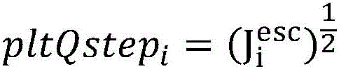
16. The method of solution 15, wherein the rule specifies that what is denoted as pltQstep is determined according to the following equation i Wherein i is an integer:

wherein Indicating escape codec samples and a, B and C are determined according to a second rule.
17. The method of solution 16, wherein the second rule specifies: a or B or C is equal to 1; or B is equal to 0 and C is equal to 2; or A is equal to 1/4, B is equal to 0, and C is equal to 2; or A equals 1, B equals 0, and C equals 2; or A or B or C is equal to 2 K Or-2 K Wherein K is in [ -M, N [ - ]]Wherein M and N are not less than 0.
18. The method of solution 15, wherein the rate-distortion cost of escape codec samples for a color component is estimated according to the following equation:

wherein D i esc Representing estimated distortion, λ, of escape codec samples i Representing the Lagrangian parameter, R i esc Is an estimated number of codec bits of the escape codec samples and X, Y and Z are determined according to a third rule.
19. The method of solution 18, wherein the second rule specifies: x or Y or Z is equal to 1; or X or Y or Z is equal to 0; or X and Y are equal to 1 and Z is equal to 0; or X is equal to 0, Y is equal to 1, and Z is equal to 0; or X or Y or Z is equal to 2 K Or-2 K Where K is an integer value.
20. The method according to any of solutions 15 to 19, wherein the distortion of quantized escape codec samples is determined using the following formula:

wherein Qstep i Representing quantization step sizes of component i, m and n being according to the fourthTwo variables of the rule.
21. The method of solution 20, wherein a third rule specifies: m or n is equal to 1; or m or n is equal to 0; or m is equal to 2 and n is equal to 2; or m is equal to 2 and n is equal to 6; or m or n is equal to 2 K Or-2 K Wherein K is an integer value.
22. The method of any of solutions 19-21, wherein K is in the range of [ -M, N ], where M and N are not less than 0.
23. The method according to any of solutions 15-19, wherein the distortion of the quantized escape symbols is determined according to:
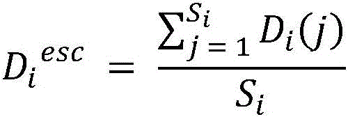
wherein S i Number of total samples, D, representing component i i (j) Representing the quantization distortion of the jth sample of component i.
24. The method according to any of solutions 15-19, wherein the distortion of the quantized escape symbols is determined by estimating the maximum distortion within a block using the following equation:

where max is the max-value operation.
25. The method according to any of solutions 15-19, wherein the distortion of the quantized escape symbols is determined by estimating the minimum distortion within a block using the following equation:

where min is the minimum operation.
26. The method according to any of solutions 1-24, wherein is represented as R i esc Of quantized escape codec samplesThe rate is estimated as minRate, which represents the minimum bit length of the quantized escape codec samples.
27. The method of solution 25, wherein R is the quantization level of an escape sample if binarized with a golomb index of k order codec i esc Is estimated as k +1.
28. The method of solution 25, wherein R is the quantization level of an escape sample if binarized with fixed length coding i esc Is estimated as (bitDepth) i -log 2 Qstep i ),Qstep i Represents the quantization step size according to the associated quantization parameter QP i Is/are as follows And deduct, bitDepth i Representing the inner codec bit depth of component i.
29. The method according to any of solutions 1-24, wherein if the quantization level of an escape sample is binarized with order-k golomb index coding, then R is used i esc The rate of the represented quantized escape codec samples is estimated as (P minRate + Q maxRate)/(P + Q), where maxRate represents the maximum bit length of the quantized escape codec samples, and P and Q are two variables representing weighting factors.
30. The method of solution 28, wherein P = Q =1 or P = Q =0.
31. The method of any of solutions 1-24, wherein R i esc The rate of the quantized escape codec samples represented is estimated as f maxRate, where f represents [0,1 [ ]]A scaling factor in the range of (1).
32. The method of any of solutions 1-24, wherein R i esc The rate of the quantized escape codec samples represented is estimated as Max [ maxRate-offset, minRate]Where offset represents an offset parameter.
33. The method of solution 32, where offset is equal to 4 and minRate is equal to 4, and wherein maxRate depends on Qstep i And bitDepth i Determined maximum codec level/ max 。
34. The method of solution 32, where offset is equal to 2 K Where K is an integer value.
35. The method of solution 34, wherein K is in the range of [0, N ], where N is not less than zero.
36. The method according to any of solutions 1-24, wherein depending on the binarization method, by R i esc The rate of the represented quantized escape codec samples is estimated as [0,maxrate []Any value within the range of (a).
The following solution illustrates an example embodiment of the techniques discussed in the previous section (e.g., item 4).
37. A method (e.g., method 1200 depicted in fig. 12) of encoding video data, comprising: determining (1202), for a transition between a current video block of a video and a bitstream of the video, one or more clustering steps for a palette mode representation of one or more component blocks of the current video block; and performing (1204) a transformation based on the one or more clustering steps; wherein the one or more clustering steps are determined based on a quantization step of the current video block or an index of one or more lists of quantization parameters.
38. The method of solution 37, wherein the one or more lists comprise a first list for a double-tree open case and a second list for a double-tree closed case.
39. The method of solution 37, wherein the first list for determining the first clustering step size for the first component is different from the second list for determining the second clustering step size for the second component or the third component.
The following solution illustrates an example embodiment of the techniques discussed in the previous section (e.g., item 5).
40. A method of encoding and decoding video data (e.g., method 1300 depicted in fig. 13), comprising: determining (1302), for a transition between a current video block of the video and a bitstream of the video, whether to use a predictor palette for predicting a palette for the transition based on a codec condition; and performing (1304) the conversion based on the determination.
41. The method of solution 40, wherein the codec condition corresponds to using a quantization parameter that is greater than or not less than a threshold.
42. The method of solution 41, wherein the coding conditions further comprise a palette step size of zero.
43. The method of solution 41, wherein determining comprises determining not to use a predictor palette because a palette step size is equal to zero.
44. The method of any of solutions 1-43, wherein converting comprises encoding the current video block into a bitstream.
45. The method of any of solutions 1-43, wherein converting comprises decoding the current video block from a bitstream.
46. A method of storing a bitstream representing a video to a computer-readable recording medium, comprising: generating a bitstream from the video according to the method described in any one or more of solutions 1 to 43; and writing the bitstream to a computer-readable recording medium.
47. An apparatus for processing video data, comprising a processor and a non-transitory memory having instructions thereon, wherein the instructions, when executed by the processor, cause the processor to implement the method recited in one or more of solutions 1 to 43.
48. A non-transitory computer-readable recording medium storing a bitstream of a video generated by a method performed by a video processing apparatus, wherein the method comprises: generating a bitstream from the current video block according to the method described in any one or more of solutions 1 to 43.
49. A computer readable medium storing a bitstream generated according to any one or more of solutions 1 to 16.
The disclosed and other solutions, examples, embodiments, modules, and functional operations described herein may be implemented in digital electronic circuitry, or in computer software, firmware, or hardware (including the structures disclosed in this document and their structural equivalents), or in combinations of one or more of them. The disclosed and other embodiments may be implemented as one or more computer program products, i.e., one or more modules of computer program instructions encoded on a computer-readable medium for execution by, or to control the operation of, data processing apparatus. The computer readable medium can be a machine-readable storage device, a machine-readable storage substrate, a memory device, a composition of matter effecting a machine-readable propagated signal, or a combination of one or more of them. The term "data processing apparatus" encompasses all apparatus, devices, and machines for processing data, including by way of example a programmable processor, a computer, or multiple processors or computers. The apparatus can include, in addition to hardware, code that creates an execution environment for the computer program in question, e.g., code that constitutes processor firmware, a protocol stack, a database management system, an operating system, or a combination of one or more of them. A propagated signal is an artificially generated signal, e.g., a machine-generated electrical, optical, or electromagnetic signal, that is generated to encode information for transmission to suitable receiver apparatus.
A computer program (also known as a program, software application, script, or code) can be written in any form of programming language, including compiled or interpreted languages, and it can be deployed in any form, including as a stand-alone program or as a module, component, subroutine, or other unit suitable for use in a computing environment. A computer program does not necessarily correspond to a file in a file system. A program can be stored in a portion of a file that holds other programs or data (e.g., one or more scripts stored in a markup language document), in a single file dedicated to the program in question, or in multiple coordinated files (e.g., files that store one or more modules, sub programs, or portions of code). A computer program can be deployed to be executed on one computer or on multiple computers that are located at one site or distributed across multiple sites and interconnected by a communication network.
The processes and logic flows described in this document can be performed by one or more programmable processors executing one or more computer programs to perform functions by operating on input data and generating output. The processes and logic flows can also be performed by, and apparatus can also be implemented as, special purpose logic circuitry, e.g., an FPGA (field programmable gate array) or an ASIC (application-specific integrated circuit).
Processors suitable for the execution of a computer program include, by way of example, both general and special purpose microprocessors, and any one or more processors of any kind of digital computer. Generally, a processor will receive instructions and data from a read-only memory or a random access memory or both. The essential elements of a computer are a processor for executing instructions and one or more memory devices for storing instructions and data. Generally, a computer will also include, or be operatively coupled to receive data from or transfer data to, or both, one or more mass storage devices for storing data, e.g., magnetic, magneto-optical disks, or optical disks. However, a computer need not have such a device. Computer-readable media suitable for storing computer program instructions and data include all forms of non-volatile memory, media and memory devices, including by way of example: semiconductor memory devices such as EPROM, EEPROM, and flash memory devices; magnetic disks, such as internal hard disks or removable disks; magneto-optical disks; and CD-ROM and DVD-ROM disks. The processor and the memory can be supplemented by, or incorporated in, special purpose logic circuitry.
Although this patent document contains many specifics, these should not be construed as limitations on the scope of any subject matter or claimed content, but rather as descriptions of features specific to particular embodiments of particular technologies. Certain features that are described in this patent document in the context of separate embodiments can also be implemented in combination in a single embodiment. Conversely, various features that are described in the context of a single embodiment can also be implemented in multiple embodiments separately or in any suitable subcombination. Furthermore, although features may be described above as acting in certain combinations and even initially claimed as such, one or more features from a claimed combination can in some cases be excised from the combination, and the claimed combination may be directed to a subcombination or variation of a subcombination.
Similarly, while operations are depicted in the drawings in a particular order, this should not be understood as requiring that such operations be performed in the particular order shown or in sequential order, or that all illustrated operations be performed, to achieve desirable results. Moreover, the separation of various system components in the embodiments described in this patent document should not be understood as requiring such separation in all embodiments.
Only some embodiments and examples are described and other embodiments, enhancements and variations can be made based on what is described and illustrated in this patent document.
Claims (49)


Applications Claiming Priority (3)
| Application Number | Priority Date | Filing Date | Title |
|---|---|---|---|
| CNPCT/CN2019/130368 | 2019-12-31 | ||
| CN2019130368 | 2019-12-31 | ||
| PCT/CN2020/141897 WO2021136470A1 (en) | 2019-12-31 | 2020-12-31 | Clustering based palette mode for video coding |
Publications (1)
| Publication Number | Publication Date |
|---|---|
| CN115211118A true CN115211118A (en) | 2022-10-18 |
Family
ID=76685857
Family Applications (1)
| Application Number | Title | Priority Date | Filing Date |
|---|---|---|---|
| CN202080091423.2A Pending CN115211118A (en) | 2019-12-31 | 2020-12-31 | Cluster-based palette mode for video coding |
Country Status (2)
| Country | Link |
|---|---|
| CN (1) | CN115211118A (en) |
| WO (1) | WO2021136470A1 (en) |
Citations (3)
| Publication number | Priority date | Publication date | Assignee | Title |
|---|---|---|---|---|
| US20120224640A1 (en) * | 2011-03-04 | 2012-09-06 | Qualcomm Incorporated | Quantized pulse code modulation in video coding |
| WO2015096812A1 (en) * | 2013-12-27 | 2015-07-02 | Mediatek Inc. | Method and apparatus for palette coding with cross block prediction |
| US20170085891A1 (en) * | 2015-09-18 | 2017-03-23 | Qualcomm Incorporated | Restriction of escape pixel signaled values in palette mode video coding |
Family Cites Families (4)
| Publication number | Priority date | Publication date | Assignee | Title |
|---|---|---|---|---|
| JP4607953B2 (en) * | 2004-04-21 | 2011-01-05 | スリップストリーム データ インコーポレイテッド | Method, system, and software product for color image coding |
| US9826242B2 (en) * | 2014-03-14 | 2017-11-21 | Qualcomm Incorporated | Palette-based video coding |
| US9654806B2 (en) * | 2014-03-26 | 2017-05-16 | Qualcomm Incorporated | Determining palette size, palette entries and filtering of palette coded blocks in video coding |
| US9860548B2 (en) * | 2014-05-23 | 2018-01-02 | Hfi Innovation Inc. | Method and apparatus for palette table prediction and signaling |
-
2020
- 2020-12-31 CN CN202080091423.2A patent/CN115211118A/en active Pending
- 2020-12-31 WO PCT/CN2020/141897 patent/WO2021136470A1/en not_active Ceased
Patent Citations (5)
| Publication number | Priority date | Publication date | Assignee | Title |
|---|---|---|---|---|
| US20120224640A1 (en) * | 2011-03-04 | 2012-09-06 | Qualcomm Incorporated | Quantized pulse code modulation in video coding |
| WO2015096812A1 (en) * | 2013-12-27 | 2015-07-02 | Mediatek Inc. | Method and apparatus for palette coding with cross block prediction |
| US20160309183A1 (en) * | 2013-12-27 | 2016-10-20 | Mediatek Inc. | Method and Apparatus for Palette Coding with Cross Block Prediction |
| US20190110071A1 (en) * | 2013-12-27 | 2019-04-11 | Mediatek Inc. | Method and Apparatus for Palette Coding with Cross Block Prediction |
| US20170085891A1 (en) * | 2015-09-18 | 2017-03-23 | Qualcomm Incorporated | Restriction of escape pixel signaled values in palette mode video coding |
Also Published As
| Publication number | Publication date |
|---|---|
| WO2021136470A1 (en) | 2021-07-08 |
Similar Documents
| Publication | Publication Date | Title |
|---|---|---|
| CN115244924B (en) | Signaling notification for cross-component adaptive loop filter | |
| US20230105972A1 (en) | Method and system for processing video content | |
| CN113728642B (en) | Quantized residual differential pulse codec modulation representation of a codec video | |
| KR102705477B1 (en) | Palette mode with different partition structures | |
| CN115152221B (en) | Deblocking parameters for chroma components | |
| US12231693B2 (en) | Entropy coding for palette escape symbol | |
| US20230353793A1 (en) | Quantization parameter signaling in video processing | |
| CN114902680B (en) | Combined use of adaptive color conversion and differential encoding and decoding for video | |
| CN114946180B (en) | Deblocking filtering using quantization parameter information | |
| CN117319649A (en) | Residual encoding and decoding of transformed skipped blocks | |
| CN115176460B (en) | Palette mode for local dual trees | |
| CN115211123A (en) | General constraint information for video coding and decoding | |
| CN114946187B (en) | Joint coding and adaptive color transformation of chroma residual | |
| CN115299063B (en) | Transform skip residual coding | |
| JP7753320B2 (en) | Using Subpictures and Tiles in Video Coding | |
| US20240022725A1 (en) | Adaptive dependent quantization | |
| JP2025026941A (en) | Entropy coding for motion-precision syntax. | |
| CN115066899A (en) | Scalable secondary transform processing of coded video | |
| US20220210419A1 (en) | Quantization parameter derivation for palette mode | |
| CN115211118A (en) | Cluster-based palette mode for video coding | |
| WO2021136486A1 (en) | Palette size signaling in video coding |
Legal Events
| Date | Code | Title | Description |
|---|---|---|---|
| PB01 | Publication | ||
| PB01 | Publication | ||
| SE01 | Entry into force of request for substantive examination | ||
| SE01 | Entry into force of request for substantive examination |