CN115195141A - Automobile roof decorative plate and pasting device thereof - Google Patents
Automobile roof decorative plate and pasting device thereof Download PDFInfo
- Publication number
- CN115195141A CN115195141A CN202210829433.2A CN202210829433A CN115195141A CN 115195141 A CN115195141 A CN 115195141A CN 202210829433 A CN202210829433 A CN 202210829433A CN 115195141 A CN115195141 A CN 115195141A
- Authority
- CN
- China
- Prior art keywords
- plate
- positioning
- panel
- outer plate
- upper die
- Prior art date
- Legal status (The legal status is an assumption and is not a legal conclusion. Google has not performed a legal analysis and makes no representation as to the accuracy of the status listed.)
- Pending
Links
Images


Classifications
-
- B—PERFORMING OPERATIONS; TRANSPORTING
- B29—WORKING OF PLASTICS; WORKING OF SUBSTANCES IN A PLASTIC STATE IN GENERAL
- B29C—SHAPING OR JOINING OF PLASTICS; SHAPING OF MATERIAL IN A PLASTIC STATE, NOT OTHERWISE PROVIDED FOR; AFTER-TREATMENT OF THE SHAPED PRODUCTS, e.g. REPAIRING
- B29C65/00—Joining or sealing of preformed parts, e.g. welding of plastics materials; Apparatus therefor
- B29C65/48—Joining or sealing of preformed parts, e.g. welding of plastics materials; Apparatus therefor using adhesives, i.e. using supplementary joining material; solvent bonding
- B29C65/4805—Joining or sealing of preformed parts, e.g. welding of plastics materials; Apparatus therefor using adhesives, i.e. using supplementary joining material; solvent bonding characterised by the type of adhesives
-
- B—PERFORMING OPERATIONS; TRANSPORTING
- B29—WORKING OF PLASTICS; WORKING OF SUBSTANCES IN A PLASTIC STATE IN GENERAL
- B29C—SHAPING OR JOINING OF PLASTICS; SHAPING OF MATERIAL IN A PLASTIC STATE, NOT OTHERWISE PROVIDED FOR; AFTER-TREATMENT OF THE SHAPED PRODUCTS, e.g. REPAIRING
- B29C66/00—General aspects of processes or apparatus for joining preformed parts
- B29C66/40—General aspects of joining substantially flat articles, e.g. plates, sheets or web-like materials; Making flat seams in tubular or hollow articles; Joining single elements to substantially flat surfaces
- B29C66/47—Joining single elements to sheets, plates or other substantially flat surfaces
Landscapes
- Engineering & Computer Science (AREA)
- Mechanical Engineering (AREA)
- Moulds For Moulding Plastics Or The Like (AREA)
Abstract
本发明公开了一种汽车顶盖装饰板,包括外板和内板,其中:所述外板远离所述内板的上顶面为弧面,所述外板和所述内板可以是现有技术中高分子材料制成;所述外板位于所述内板外部,所述外板与所述内板之间通过粘贴固定,且所述内板和所述外板之间具有空腔。空腔的设置不仅便于增大汽车顶盖装饰板的抗振性能,且增大其隔热性能,另一方面便于外板和内板在粘贴时施加压力使外板与内板粘贴更加牢固。一种粘贴装置,用于加工上述汽车顶盖装饰板该装置使外板和内板粘贴更加稳固。
The invention discloses an automobile roof trim panel, comprising an outer panel and an inner panel, wherein: the upper top surface of the outer panel away from the inner panel is an arc surface, and the outer panel and the inner panel may be existing It is made of polymer material in the prior art; the outer plate is located outside the inner plate, the outer plate and the inner plate are fixed by sticking, and there is a cavity between the inner plate and the outer plate. The arrangement of the cavity is not only convenient to increase the anti-vibration performance of the car roof trim panel, but also to increase its thermal insulation performance, on the other hand, it is convenient for the outer panel and the inner panel to apply pressure when pasting, so that the outer panel and the inner panel are more firmly attached. A sticking device is used for processing the above-mentioned automobile roof trim panel, and the device makes the sticking of the outer panel and the inner panel more stable.
Description
技术领域technical field
本发明涉及汽车相关部件加工设备技术领域,尤其涉及一种汽车顶盖装饰板及其粘贴装置。The invention relates to the technical field of automobile-related parts processing equipment, in particular to an automobile roof trim panel and a sticking device thereof.
背景技术Background technique
汽车顶盖装饰板大部分为钢板或高分子材料锻造或注塑成型,钢板材料的顶盖装饰板质量重且成本高且不便于成型,高分子材料注塑成型的汽车顶盖虽然容易成型,但是其强度与钢板制成的汽车顶盖装饰板相差较多。Most of the car roof decorative panels are forged or injection molded from steel plates or polymer materials. The roof decorative panels of steel plate materials are heavy in weight, high in cost and inconvenient to form. Although the car roofs injection molded from polymer materials are easy to form, they are difficult to form. The strength is much different from that of the car roof trim panel made of steel plate.
发明内容SUMMARY OF THE INVENTION
为解决背景技术中存在的技术问题,以实现质量轻且强度大的汽车顶盖装饰板,本发明提出一种汽车顶盖装饰板及其粘贴装置。In order to solve the technical problems existing in the background art and to realize a vehicle roof trim panel with light weight and high strength, the present invention provides a vehicle roof trim panel and a sticking device thereof.
本发明提出的一种汽车顶盖装饰板,包括外板和内板,其中:A vehicle roof trim panel proposed by the present invention includes an outer panel and an inner panel, wherein:
所述外板远离所述内板的上顶面为弧面,所述外板和所述内板可以是现有技术中高分子材料制成;所述外板位于所述内板外部,所述外板与所述内板之间通过粘贴固定,且所述内板和所述外板之间具有空腔。The upper top surface of the outer panel away from the inner panel is an arc surface, and the outer panel and the inner panel may be made of polymer materials in the prior art; the outer panel is located outside the inner panel, and the outer panel is located outside the inner panel. The outer plate and the inner plate are fixed by sticking, and there is a cavity between the inner plate and the outer plate.
空腔的设置不仅便于增大汽车顶盖装饰板的抗振性能,且增大其隔热性能,另一方面便于外板和内板在粘贴时施加压力使外板与内板粘贴更加牢固。The arrangement of the cavity is not only convenient to increase the anti-vibration performance of the car roof trim panel, but also to increase its thermal insulation performance.
优选的,所述内板与所述外板相对的一面具有多个延伸板,多个所述延伸板与所述外板粘贴,所述延伸板与内板和外板之间形成空腔,该延伸板包括纵向延伸板和横向延伸板,所述纵向延伸板沿所述内板的长度方向设置,所述横向延伸板沿所述内板的宽度方向,相邻横向延伸板、纵向延伸板和外板、内板形成空腔,横向延伸板和纵向延伸板分别设有多个则空腔也形成多个。Preferably, the opposite side of the inner plate and the outer plate has a plurality of extension plates, the plurality of extension plates are pasted with the outer plate, and a cavity is formed between the extension plate and the inner plate and the outer plate, The extension board includes a longitudinal extension board and a transverse extension board, the longitudinal extension board is arranged along the length direction of the inner board, the transverse extension board is along the width direction of the inner board, and adjacent transverse extension boards and longitudinal extension boards A cavity is formed with the outer plate and the inner plate, and a plurality of cavities are also formed if the transversely extending plate and the longitudinally extending plate are respectively provided with a plurality of them.
一种粘贴装置,用于加工上述的汽车顶盖装饰板,包括下模、上模、升降件、吸附件和二次夹紧机构,其中:A sticking device for processing the above-mentioned automobile roof trim panel, comprising a lower mold, an upper mold, a lifting part, an adsorption part and a secondary clamping mechanism, wherein:
所述下模用于对所述内板进行定位;the lower die is used for positioning the inner panel;
所述上模用于对所述外板进行定位,且所述吸附件安装在所述上模上,所述吸附件用于对所述外板进行吸附固定;The upper mold is used for positioning the outer plate, and the adsorption part is installed on the upper mold, and the adsorption part is used for adsorption and fixation of the outer plate;
所述上模位于所述下模上方,所述外板与所述内板相对,所述升降件用于带动所述上模相对所述下模上下移动,所述升降件带动所述上模向下移动使所述外板与所述内板的粘结层初步接触,具体的升降件可以为现有技术中的机械手或电缸或气缸或其他可以带动上模移动的部件;The upper mold is located above the lower mold, the outer plate is opposite to the inner plate, the lifting member is used to drive the upper mold to move up and down relative to the lower mold, and the lifting member drives the upper mold Moving downwards makes the outer plate and the adhesive layer of the inner plate make initial contact, and the specific lifting member can be a manipulator or an electric cylinder or an air cylinder in the prior art or other components that can drive the upper die to move;
所述二次夹紧机构安装在所述上模上,当所述外板与所述内板的粘结层初步接触后,所述二次夹紧机构带动所述上模继续向下移动使所述外板与所述内板的粘接层压紧、抵触进而实现将所述外板和所述内板粘贴;The secondary clamping mechanism is installed on the upper mold. After the outer plate and the adhesive layer of the inner plate are in initial contact, the secondary clamping mechanism drives the upper mold to continue to move downward to make the outer plate move downward. The adhesive layer between the outer plate and the inner plate is compressed and collided, so as to realize the adhesion of the outer plate and the inner plate;
加工过程中首先将内板放置在下模上并且下模对内板进行定位,然后将外板放置在上模上并对其定位,吸附件通过负压将外板吸附固定在所述上模上,然后通过外界机器人通过移动上模将外板移动至涂胶工位,然后对外板与接触位置部分涂抹聚氨酯胶水,且在内板与下模接触位置部分处涂抹热熔胶,然后外界机器人将外板一定至于内板相对,然后通过升降件带动上模向下移动使外板上的聚氨酯胶水与内板接触,且内板上的热熔胶与外板接触,通过热熔胶和聚氨酯胶水的结合便于保证外板内板连接稳固的基础上,由于热熔胶和聚氨酯胶水干的速度不同,便于加工,,然后二次夹紧机构继续带动上模向下移动微小距离使上模与下模通过热熔胶与聚氨酯胶水挤压粘贴牢固,然后松开二次夹紧机构,夹紧气缸松开,升降件带动上模离开下模,此时粘贴在一起的内板和外板在自身重力下留在下模上,便于取出固定在一起的内板和外板。In the process of processing, the inner plate is first placed on the lower mold and the lower mold positions the inner plate, and then the outer plate is placed on the upper mold and positioned, and the outer plate is adsorbed and fixed on the upper mold by the suction part through negative pressure. , and then move the outer plate to the gluing station by moving the upper mold by an external robot, then apply polyurethane glue to the contact position of the outer plate and apply hot melt glue to the contact position of the inner plate and the lower mold, and then the external robot will The outer plate must be opposite to the inner plate, and then the upper mold is moved down by the lifting piece to make the polyurethane glue on the outer plate contact with the inner plate, and the hot melt adhesive on the inner plate is in contact with the outer plate. On the basis of ensuring the stable connection of the outer and inner plates, the drying speed of the hot-melt glue and the polyurethane glue is different, which is convenient for processing, and then the secondary clamping mechanism continues to drive the upper mold to move down a small distance to make the upper mold and the lower mold. The mold is pressed and pasted firmly by hot melt adhesive and polyurethane glue, and then the secondary clamping mechanism is released, the clamping cylinder is released, and the lifting piece drives the upper mold to leave the lower mold. Gravity remains on the lower die for easy removal of the inner and outer panels that are fastened together.
优选的,还包括第一定位组件,所述第一定位组件包括第一移动机构和第一定位柱,具体的,所述第一移动机构可以为现有技术中油缸、气缸或电缸等可以带动部件直线移动的机构,所述第一移动机构安装在所述上模上,所述第一定位柱安装在所述第一移动机构的移动端,所述外板的的侧面设有预成型延伸件,所述预成型延伸件上开有定位孔,所述定位孔与所述第一定位柱匹配。Preferably, it also includes a first positioning assembly, and the first positioning assembly includes a first moving mechanism and a first positioning column. Specifically, the first moving mechanism may be an oil cylinder, an air cylinder or an electric cylinder in the prior art. A mechanism for driving components to move linearly, the first moving mechanism is installed on the upper mold, the first positioning column is installed on the moving end of the first moving mechanism, and the side of the outer plate is provided with a preform An extension piece, the preformed extension piece is provided with a positioning hole, and the positioning hole is matched with the first positioning column.
优选的,所述第一定位组件设有两组,且两组第一定位组件位于所述外板的同侧,所述上模还设有侧面定位板,所述侧面定位板位于远离所述第一定位组件的外板的另一侧并对外板远离所述第一定位组件的一侧面抵触,在固定外板时外板的一侧与侧面定位板抵触,进而通过侧面定位板进行辅助定位。Preferably, there are two sets of the first positioning components, and the two sets of first positioning components are located on the same side of the outer plate, and the upper mold is further provided with a side positioning plate, and the side positioning plate is located away from the The other side of the outer plate of the first positioning component and the side of the outer plate away from the first positioning component are in contact. When the outer plate is fixed, one side of the outer plate is in conflict with the side positioning plate, and then the side positioning plate is used for auxiliary positioning. .
优选的,还包括第二定位组件,还包括第二定位组件,所述第二定位组件包括定位套筒,所述定位套筒安装在所述下模上,所述内板远离所述外板的一面具有延伸柱,所述延伸柱与所述定位套筒匹配。Preferably, it further includes a second positioning assembly, and further includes a second positioning assembly, the second positioning assembly includes a positioning sleeve, the positioning sleeve is mounted on the lower mold, and the inner plate is far away from the outer plate There is an extension column on one side, and the extension column is matched with the positioning sleeve.
优选的,所述二次夹紧机构包括压头和驱动机构,所述驱动机构安装在所述上模上,所述压头安装在所述驱动机构的移动端,所述驱动机构用于带动所述压头在竖直面内做曲线运动。Preferably, the secondary clamping mechanism includes a pressing head and a driving mechanism, the driving mechanism is mounted on the upper die, the pressing head is mounted on the moving end of the driving mechanism, and the driving mechanism is used for driving The indenter makes a curvilinear motion in a vertical plane.
优选的,所述驱动机构包括夹紧气缸、三角连接板、连杆和活动杆,其中:Preferably, the driving mechanism includes a clamping cylinder, a triangular connecting plate, a connecting rod and a movable rod, wherein:
所述夹紧气缸固定在所述上模上,所述三角连接板的一个转角固定在所述夹紧气缸的伸缩端,所述三角连接板的另一个转角转动安装在所述上模上,所述三角连接板的第三个转角与所述连杆转动连接,且所述连杆的另一端与所述活动杆的中部转动连接,所述活动杆的一端与所述上模转动连接,所述压头安装在所述活动杆的另一端。The clamping cylinder is fixed on the upper die, one corner of the triangular connecting plate is fixed on the telescopic end of the clamping cylinder, and the other corner of the triangular connecting plate is rotatably mounted on the upper die, The third corner of the triangular connecting plate is rotatably connected with the connecting rod, and the other end of the connecting rod is rotatably connected with the middle of the movable rod, and one end of the movable rod is rotatably connected with the upper die, The pressing head is mounted on the other end of the movable rod.
优选的,下模包括底板和多个支撑块,多个所述支撑块可拆卸安装在所述底板上,且所述支撑块的上表面用于对所述内板的下底面进行支撑。Preferably, the lower mold includes a bottom plate and a plurality of support blocks, the plurality of support blocks are detachably mounted on the bottom plate, and the upper surfaces of the support blocks are used to support the lower bottom surface of the inner plate.
优选的,所述支撑块的上表面开有通槽,所述通槽用于容纳所述内板底面上的凸起。Preferably, a through groove is formed on the upper surface of the support block, and the through groove is used for accommodating the protrusion on the bottom surface of the inner plate.
本发明中,所提出的汽车顶盖装饰板及其粘贴装置,通过外板和内板的设置进而便于增大其整体的强度且外板和内板可以为高分子材料制成,在保证汽车顶盖装饰板强度的前提下降低其质量,进而实现汽车省油的技术效果。In the present invention, the proposed automobile roof trim panel and its sticking device are convenient to increase the overall strength through the arrangement of the outer panel and the inner panel. Under the premise of the strength of the top cover decorative plate, the quality is reduced, and the technical effect of fuel saving of the automobile is realized.
本发明的附加方面和优点将在下面的描述中部分给出,部分将从下面的描述中变得明显,或通过本发明的实践了解到。Additional aspects and advantages of the present invention will be set forth, in part, from the following description, and in part will be apparent from the following description, or may be learned by practice of the invention.
附图说明Description of drawings
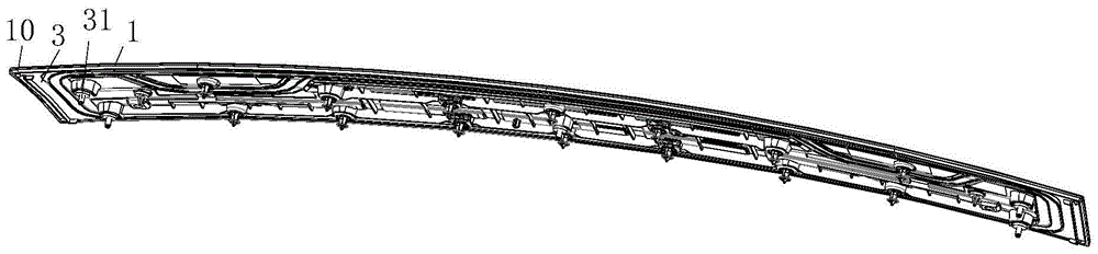
图1为本发汽车顶盖装饰板结构示意图;Fig. 1 is the structural schematic diagram of the car roof trim panel of the present invention;
图2为本发明汽车顶盖装饰板爆炸结构示意图;2 is a schematic diagram of an explosion structure of an automobile roof trim panel of the present invention;
图3为本发明粘贴装置结构示意图;3 is a schematic structural diagram of the sticking device of the present invention;
图4为本发明粘贴装置上模机构示意图;Fig. 4 is the schematic diagram of the upper die mechanism of the sticking device of the present invention;
图5为本发明A区局部放大图;Fig. 5 is the partial enlarged view of A area of the present invention;
图6为本发明B区局部放大图;Fig. 6 is the partial enlarged view of B area of the present invention;
图7为本发明C区局部放大图;Fig. 7 is the partial enlarged view of C area of the present invention;
图8为本发明下模结构示意图;Fig. 8 is a schematic diagram of the lower die structure of the present invention;
图9为本发明D区局部放大图;Fig. 9 is the partial enlarged view of D area of the present invention;
图10为本发明下模另一角度结构示意图。FIG. 10 is a schematic diagram of another angle structure of the lower die of the present invention.
具体实施方式Detailed ways
下面详细描述本发明的实施例,所述实施例的示例在附图中表示,其中自始至终相同或类似的符号表示相同或类似的元件或具有相同或类似功能的元件。下面通过参考附图描述的实施例是示例性的,仅用于解释本发明,而不能理解对本发明的限制。The following describes in detail the embodiments of the present invention, examples of which are illustrated in the accompanying drawings, wherein the same or similar symbols refer to the same or similar elements or elements having the same or similar functions throughout. The embodiments described below with reference to the accompanying drawings are exemplary and are only used to explain the present invention, but not to limit the present invention.
需要理解的是,术语“中心”、“纵向”、“横向”、“长度”、“宽度”、“厚度”、“上”、“下”、“前”、“后”、“左”、“右”、“竖直”、“水平”、“顶”、“底”“内”、“外”、“顺时针”、“逆时针”、“轴向”、“径向”、“周向”等指示的方位或位置关系为基于附图所示的方位或位置关系,仅是为了便于描述本发明和简化描述,而不是指示或暗示所指的装置或元件必须具有特定的方位、以特定的方位构造和操作,因此不能理解为对本发明的限制。It is to be understood that the terms "center", "longitudinal", "lateral", "length", "width", "thickness", "top", "bottom", "front", "rear", "left", "Right", "Vertical", "Horizontal", "Top", "Bottom", "Inner", "Outer", "Clockwise", "Counterclockwise", "Axial", "Radial", "Circumferential" The orientation or positional relationship indicated by "to" and the like is based on the orientation or positional relationship shown in the accompanying drawings, which is only for the convenience of describing the present invention and simplifying the description, rather than indicating or implying that the indicated device or element must have a specific orientation, so as to The specific orientation configuration and operation are therefore not to be construed as limitations of the present invention.
此外,术语“第一”、“第二”仅用于描述目的,而不能理解为指示或暗示相对重要性或者隐含指明所指示的技术特征的数量。由此,限定有“第一”、“第二”的特征可以明示或者隐含地包括至少一个该特征。在本发明的描述中,“多个”的含义是至少两个,例如两个,三个等,除非另有明确具体的限定。In addition, the terms "first" and "second" are only used for descriptive purposes, and should not be construed as indicating or implying relative importance or implying the number of indicated technical features. Thus, a feature delimited with "first", "second" may expressly or implicitly include at least one of that feature. In the description of the present invention, "plurality" means at least two, such as two, three, etc., unless otherwise expressly and specifically defined.
在本发明中,除非另有明确的规定和限定,术语“安装”、“相连”、“连接”、“固定”等术语应做广义理解,例如,可以是固定连接,也可以是可拆卸连接,或成一体;可以是机械连接,也可以是电连接或彼此可通讯;可以是直接相连,也可以通过中间媒介间接相连,可以是两个元件内部的连通或两个元件的相互作用关系,除非另有明确的限定。对于本领域的普通技术人员而言,可以根据具体情况理解上述术语在本发明中的具体含义。In the present invention, unless otherwise expressly specified and limited, the terms "installed", "connected", "connected", "fixed" and other terms should be understood in a broad sense, for example, it may be a fixed connection or a detachable connection , or integrated; it can be a mechanical connection or an electrical connection or can communicate with each other; it can be directly connected or indirectly connected through an intermediate medium, it can be the internal connection of two components or the interaction relationship between the two components, unless otherwise expressly qualified. For those of ordinary skill in the art, the specific meanings of the above terms in the present invention can be understood according to specific situations.
在本发明中,除非另有明确的规定和限定,第一特征在第二特征“上”或“下”可以是第一和第二特征直接接触,或第一和第二特征通过中间媒介间接接触。而且,第一特征在第二特征“之上”、“上方”和“上面”可是第一特征在第二特征正上方或斜上方,或仅仅表示第一特征水平高度高于第二特征。第一特征在第二特征“之下”、“下方”和“下面”可以是第一特征在第二特征正下方或斜下方,或仅仅表示第一特征水平高度小于第二特征。In the present invention, unless otherwise expressly specified and limited, a first feature "on" or "under" a second feature may be in direct contact between the first and second features, or the first and second features indirectly through an intermediary touch. Also, the first feature being "above", "over" and "above" the second feature may mean that the first feature is directly above or obliquely above the second feature, or simply means that the first feature is level higher than the second feature. The first feature being "below", "below" and "below" the second feature may mean that the first feature is directly below or obliquely below the second feature, or simply means that the first feature has a lower level than the second feature.
如图1-2所示的一种汽车顶盖装饰板,包括外板1和内板3,其中:As shown in Figure 1-2, an automobile roof trim panel includes an outer panel 1 and an
外板1位于内板3的外部且与内板3通过粘贴方式固定连接,外板1远离内板3的上顶面为弧面,外板1和内板3可以是现有技术中高分子塑料材料制成;The outer panel 1 is located outside the
具体的,外板1与内板3相对的一面为平面,内板3与外板1相对的一面具有延伸板30,延伸板30与外板1粘贴,延伸板30与外板1为面接触,延伸板30包括纵向延伸板301和横向延伸板300,纵向延伸板301沿内板3的长度方向设置的条形板,横向延伸板300沿内板3的宽度方向设置的条形板,相邻横向延伸板300、纵向延伸板301和外板1、内板3形成空腔,横向延伸板300和纵向延伸板301分别设有多个则空腔也形成多个,延伸板30的设置不仅增大了整体的强度也便于形成空腔;Specifically, the opposite side of the outer plate 1 and the
空腔的设置不仅便于增大汽车顶盖装饰板的抗振性能,且增大其隔热性能;The setting of the cavity is not only convenient to increase the anti-vibration performance of the vehicle roof trim panel, but also to increase its thermal insulation performance;
具体的,外板1的侧面具有延伸框10,延伸框10与外板1组成安装槽,内板3安装在安装槽中,进一步便于外板1与内板3组装时的定位;Specifically, the side of the outer panel 1 has an
为了便于内板3和外板1的组装,在内板3远离外板1的一侧设有延伸柱31;在加工过程中为了便于外板1的定位,在延伸框10的外侧设有预成型延伸件11,该预成型延伸件11上开有定位孔110,且该预成型定位件与外板1一体成型,待外板1和内板3组成后通过切割方式将预成型定位件切除。In order to facilitate the assembly of the
如图3-10所示,一种粘贴装置,用于加工上述的汽车顶盖装饰板,包括机架(图中未示出)、下模4、上模5、升降件(图中未示出)、第二定位组件6、第一定位组件7、吸附件8和二次夹紧机构9,其中:As shown in Figure 3-10, a sticking device for processing the above-mentioned automobile roof trim panel includes a frame (not shown in the figure), a
上模5通过升降件安装在机架上,在本实施例中升降件为机械手,由于机械手带动板状部件移动为很成熟的技术,因此在附图中并未体现机械手结构;The
下模4安装在机架上(下模4固定在机架上也是很常规的技术手段,在附图中并未将其画出),下模4用于对内板3进行定位;The
具体的,下模4包括底板40和多个支撑块41,多个支撑块41通过螺钉可拆卸安装在底板40上,且支撑块41的上表面用于对内板3的下底面进行支撑;Specifically, the
为了进一步更好的支撑,支撑块41的上表面开有通槽410,通槽410用于容纳内板3底面上的凸起;For further better support, the upper surface of the
第二定位组件6包括安装件60和定位套筒61,第定位套筒61通过安装件60可拆卸安装在下模4的底板40上,具体的,安装件60通过螺栓可拆卸安装在底板40上,定位套筒61通过卡接方式固定在安装件60上,内板3远离外板1的一面具有延伸柱31,延伸柱31与定位套筒61匹配;The second positioning assembly 6 includes a mounting
第二定位组件6设有多组,且延伸柱31也设有多个,一个延伸柱31与一个第二定位组件6对应;There are multiple sets of the second positioning assembly 6, and there are also multiple extension columns 31, and one extension column 31 corresponds to one second positioning assembly 6;
具体的,底板40上的支撑块41设有两组,一组支撑块41用于对一块内板3支撑,两组支撑块41上的内板3相互平行;Specifically, there are two groups of support blocks 41 on the
上模5用于对外板1进行定位,且吸附件8安装在上模5上,吸附件8用于对外板1进行吸附固定;The
具体的,上模5包括顶板50和下抵触块51,下抵触块51设有多块且多块下抵触块51通过螺钉或螺栓可拆卸安装在顶板50上,任意相邻的两块下抵触块51之间具有一定空隙,下抵触块51的下底面为弧面且该弧面与外板1的顶面匹配;Specifically, the
吸附件8设有多个,且吸附件8设在两块抵触块之间,吸附件8包括吸盘80和通气管81,通气管81的末端安装吸盘80连接,通气管81的另一端与外界的负压设备连接;There are a plurality of suction parts 8, and the suction parts 8 are arranged between two interference blocks. The suction parts 8 include a
第一定位组件7包括第一移动机构70和第一定位柱71,具体的,第一移动机构70可以为现有技术中油缸、气缸或电缸等可以带动部件直线移动的机构,第一移动机构70安装在上模5上,第一定位柱71安装在第一移动机构70的移动端,外板1的的侧面设有预成型延伸件11,预成型延伸件11上开有定位孔110,定位孔110与第一定位柱71匹配;The
所示第一定位组件7设有两组,且两组第一定位组件7位于外板1的同侧,上模5还设有侧面定位板12,侧面定位板12位于远离第一定位组件7的外板1的另一侧并对外板1远离第一定位组件7的一侧面抵触,在固定外板1时,先将外板1的一侧与侧面定位板12抵触,然后再通过定位柱和定位孔110匹配,进而便于对外板1的固定;The shown
侧面定位板12设有两块,且一块侧面定位板12与一组定位组件相对;There are two
上模5位于下模4上方,上模5上的外板1与下模4上的内板3相对;The
为了增大精度,上模5上开有限位孔500,下模4上有限位件13,限位件13与限位孔500匹配,具体的,限位件13包括支撑柱131和球形限位头130,支撑柱131与下模4固定,球头形限位头130固定在支撑柱131上,球形限位头130与限位孔500匹配;In order to increase the accuracy, the
升降件用于带动上模5相对下模4上下移动,升降件带动上模5向下移动直至内板3的热熔胶与外板1的聚氨酯胶水初步接触,具体的升降件可以为现有技术中的机械手或电缸或气缸或其他可以带动上模5移动的部件,本实施例中升降件为机械手;The lifting member is used to drive the
二次夹紧机构9安装在上模5上,当上模5与下模4接触后二次夹紧机构9用于带动上模5继续向下移动使外板1与内板3进一步夹紧进而实现将外板1和内板3粘贴;The
二次夹紧机构9可以为现有技术中可以带动上模5向下模4靠近或远离的机构,在本实施例中具体的,二次夹紧机构9包括压头94和驱动机构,驱动机构包括夹紧气缸90、三角连接板91、连杆92和活动杆93,其中:The
夹紧气缸90固定在上模5的顶板50上,三角连接板91的一个转角固定在夹紧气缸90的伸缩端,三角连接板91的另一个转角转动安装在上模5的顶板50上,三角连接板91的第三个转角与连杆92转动连接,且连杆92的另一端与活动杆93的中部转动连接,活动杆93的一端与上模5的顶板50转动连接,压头94安装在活动杆93的另一端;The clamping
具体的,下模4上开有锁紧孔401,锁紧孔401与压头94匹配;Specifically, the
具体的,压头94为锥形,压头94的外径从靠近锁紧孔401的一端向远离锁紧孔401的一端逐渐变大;Specifically, the
优选的,锁紧孔401的截面为长方形,由于活动杆93的在夹紧气缸90、三角连接板91、连杆92的带动下使压头94末端的活动轨迹为弧线,当压头94与锁紧孔401接触后继续带动压头94移动,压头94的移动分散成水平移动和竖直移动,压头94在长方形的锁紧孔401中水平移动并带动上模5相对下模4向下移动,进而保证上模5不会相对下模4发生相互错开的水平移动,且保证带动上模5下压的动作;Preferably, the cross section of the
优选的,活动杆93远离所述活动杆93与上模5连接的一端开有滑孔930,压头94远离下模4的锁紧孔401的一端还有连接部940,连接部940贯穿滑孔930并滑动安装在滑孔930内,还包括锁紧件941,锁紧件941为锁紧螺母,锁紧件941将连接部940锁紧避免在工作过程中连接部940相对滑孔930滑动,在工作前需要调整压头94的位置;Preferably, a sliding
具体的,压头94可向靠近或远离上模5和/或下模4的中部移动;Specifically, the
具体的,三角连接板91、连杆92、活动杆93相对上模5转动的轴线平行;Specifically, the triangular connecting
二次夹紧机构9设有两组且对称分布在所述上模5的两侧,且两组二次夹紧机构9沿压头94相对上模5水平移动方向分布,进而在工作过程两组压头94相对下模4水平移动的方向相反进而抵消水平方向摩擦力,避免上模5和下模4发生水平互动。The
在加工过程中,首先将内板3放置在下模4上并且下模4对内板3进行定位,具体的,将内板3底部的延伸柱31放置在定位套筒61内,且内板3与支撑块41面接触,内板3上的凸起位于通槽410内;During the processing, the
然后将外板1放置在上模5上并对其定位,具体的,外板1在成型过程中有外板1的一侧面具有预成型延伸件11,预成型延伸件11固定在外板1的延伸框10上,首先将外板1放置在上模5上并使外板1的一侧面与侧面定位板12抵触,然后手动调整外板1使预成型延伸件11上的定位孔110与第一定位柱71相对,然后第一移动机构70带动第一定位柱71移动至定位孔110中,在此过程中外板1与侧面定位板12始终抵触,然后通过负压使吸附件8对外板1进行吸附;Then, the outer panel 1 is placed on the
机械手带动上模5移动至抹胶工位,外界相机器对外板1与内板接触外置部分涂抹聚氨酯胶水,在内板3的部分延伸板上涂抹热熔胶,然后机械手带动上模5移动使上模5位于下模4上方,且使外板1与内板2正相对,然后机械手带动上模5向下移动使下模4的限位件13与上模5的限位孔500接触,直至内板3的热熔胶与外板1的聚氨酯胶水初步接触;然后二次夹紧机构9继续带动上模5相对下模4移动使外板1的聚氨酯胶水与内板3的热熔胶抵触并压紧,且在此过程中由于空腔结构的特性使延伸板30发生微小形变便于外板1和内板3抵触更加紧密且使外板1和内板3的粘贴效果更好;The manipulator drives the
二次夹紧机构9作用一定时间后,二次夹紧机构9带动上模5归位,然后去除负压使吸附件8与外板1脱离,第一移动机构70带动第一定位柱71向远离外板1方向移动并脱离预成型延伸件11,然后升降件带动上模5向上移动远离下模4进而使上模5和下模4脱离,且粘贴固定好的外板1和内板3留在下模4上,即可将加工好的外板1和内板3从下模4的上表面取出;After the
在二次夹紧机构9带动上模5上、下移动过程中,压头相对上模5的水平移动便于成型;When the
然后在外界切削刀具或冲压作用下将预成型延伸件11去除进而完成该汽车顶盖装饰板的加工。Then, the preformed extension 11 is removed under the action of an external cutting tool or stamping to complete the processing of the vehicle roof trim panel.
以上所述,仅为本发明较佳的具体实施方式,但本发明的保护范围并不局限于此,任何熟悉本技术领域的技术人员在本发明揭露的技术范围内,根据本发明的技术方案及其发明构思加以等同替换或改变,都应涵盖在本发明的保护范围之内。The above description is only a preferred embodiment of the present invention, but the protection scope of the present invention is not limited to this. The equivalent replacement or change of the inventive concept thereof shall be included within the protection scope of the present invention.
Claims (10)
Priority Applications (1)
| Application Number | Priority Date | Filing Date | Title |
|---|---|---|---|
| CN202210829433.2A CN115195141A (en) | 2022-07-15 | 2022-07-15 | Automobile roof decorative plate and pasting device thereof |
Applications Claiming Priority (1)
| Application Number | Priority Date | Filing Date | Title |
|---|---|---|---|
| CN202210829433.2A CN115195141A (en) | 2022-07-15 | 2022-07-15 | Automobile roof decorative plate and pasting device thereof |
Publications (1)
| Publication Number | Publication Date |
|---|---|
| CN115195141A true CN115195141A (en) | 2022-10-18 |
Family
ID=83582657
Family Applications (1)
| Application Number | Title | Priority Date | Filing Date |
|---|---|---|---|
| CN202210829433.2A Pending CN115195141A (en) | 2022-07-15 | 2022-07-15 | Automobile roof decorative plate and pasting device thereof |
Country Status (1)
| Country | Link |
|---|---|
| CN (1) | CN115195141A (en) |
Cited By (1)
| Publication number | Priority date | Publication date | Assignee | Title |
|---|---|---|---|---|
| CN116890462A (en) * | 2023-06-14 | 2023-10-17 | 中国第一汽车股份有限公司 | A three-in-one bonding process for chrome trim strips |
Citations (7)
| Publication number | Priority date | Publication date | Assignee | Title |
|---|---|---|---|---|
| JP2014083904A (en) * | 2012-10-22 | 2014-05-12 | Daikyonishikawa Corp | Vehicle exterior panel |
| CN104747556A (en) * | 2015-03-16 | 2015-07-01 | 珠海格力电器股份有限公司 | Panel and substrate assembly tool |
| CN206456439U (en) * | 2017-01-23 | 2017-09-01 | 北京北方长龙新材料技术有限公司 | A kind of car light top cover |
| KR20210051680A (en) * | 2019-10-31 | 2021-05-10 | (주) 비에스티 | vehicle interior material forming apparatus |
| CN112829329A (en) * | 2020-12-31 | 2021-05-25 | 德奥福臻越智能机器人(杭州)有限公司 | Lower die mold device and surface pasting method of automobile handrail |
| WO2021142967A1 (en) * | 2020-01-19 | 2021-07-22 | 苏州库迅机器人有限公司 | Gluing device for automobile spoiler |
| CN215510682U (en) * | 2021-06-08 | 2022-01-14 | 苏州孝义家精密金属有限公司 | Pressure head assembly and pressing device |
-
2022
- 2022-07-15 CN CN202210829433.2A patent/CN115195141A/en active Pending
Patent Citations (7)
| Publication number | Priority date | Publication date | Assignee | Title |
|---|---|---|---|---|
| JP2014083904A (en) * | 2012-10-22 | 2014-05-12 | Daikyonishikawa Corp | Vehicle exterior panel |
| CN104747556A (en) * | 2015-03-16 | 2015-07-01 | 珠海格力电器股份有限公司 | Panel and substrate assembly tool |
| CN206456439U (en) * | 2017-01-23 | 2017-09-01 | 北京北方长龙新材料技术有限公司 | A kind of car light top cover |
| KR20210051680A (en) * | 2019-10-31 | 2021-05-10 | (주) 비에스티 | vehicle interior material forming apparatus |
| WO2021142967A1 (en) * | 2020-01-19 | 2021-07-22 | 苏州库迅机器人有限公司 | Gluing device for automobile spoiler |
| CN112829329A (en) * | 2020-12-31 | 2021-05-25 | 德奥福臻越智能机器人(杭州)有限公司 | Lower die mold device and surface pasting method of automobile handrail |
| CN215510682U (en) * | 2021-06-08 | 2022-01-14 | 苏州孝义家精密金属有限公司 | Pressure head assembly and pressing device |
Cited By (1)
| Publication number | Priority date | Publication date | Assignee | Title |
|---|---|---|---|---|
| CN116890462A (en) * | 2023-06-14 | 2023-10-17 | 中国第一汽车股份有限公司 | A three-in-one bonding process for chrome trim strips |
Similar Documents
| Publication | Publication Date | Title |
|---|---|---|
| CN120395372B (en) | Device equipment pressure maintaining device and equipment mechanism | |
| CN115195141A (en) | Automobile roof decorative plate and pasting device thereof | |
| CN114248112B (en) | Automatic press fitting equipment of car windscreen wiper handle | |
| CN217320870U (en) | Film material attaching device | |
| CN115744088B (en) | Automatic rivet pulling and end cover installing machine for longitudinal beam | |
| CN214336768U (en) | Glue pressing device | |
| CN109941332B (en) | Tool for adhering glass top cover and luggage rack | |
| CN213718360U (en) | Vehicle-mounted controller shell structure | |
| CN209626324U (en) | Battery cell bearing assembly, clamp and rubber coating device | |
| CN223108928U (en) | Battery cell folding forming jig | |
| CN210919704U (en) | A device for pressfitting behind rubber coating | |
| CN220660706U (en) | Electronic screen disassembling jig | |
| CN223431988U (en) | A film attachment and bubble removal component | |
| CN220113203U (en) | Automobile decorative plate assembling, positioning and processing device | |
| CN118544602A (en) | An upper mold integral tailgate pressing device | |
| CN223671876U (en) | A tooling for covering automotive door interior panels | |
| CN207952920U (en) | A kind of automobile trunk cover board supersonic welder pressing device | |
| CN220660574U (en) | Clamping jig for bonding car body | |
| CN222608592U (en) | Pressing mechanism and processing device | |
| CN223648251U (en) | Thermal insulation material bonding tool | |
| CN219204825U (en) | Heating adsorption component and laminating equipment applying same | |
| CN218020094U (en) | Packing material pipe and thermal forming jig for processing built-in limiting protrusion of packing material pipe | |
| CN222145342U (en) | Wet glue laminating jig | |
| CN221795064U (en) | Film pasting mechanism, film pasting equipment and battery production line | |
| CN220522994U (en) | Back adhesive activating mechanism |
Legal Events
| Date | Code | Title | Description |
|---|---|---|---|
| PB01 | Publication | ||
| PB01 | Publication | ||
| SE01 | Entry into force of request for substantive examination | ||
| SE01 | Entry into force of request for substantive examination |