CN115126739B - Composite type attenuation device for digital valve group pressure pulsation and test method thereof - Google Patents
Composite type attenuation device for digital valve group pressure pulsation and test method thereof Download PDFInfo
- Publication number
- CN115126739B CN115126739B CN202210833653.2A CN202210833653A CN115126739B CN 115126739 B CN115126739 B CN 115126739B CN 202210833653 A CN202210833653 A CN 202210833653A CN 115126739 B CN115126739 B CN 115126739B
- Authority
- CN
- China
- Prior art keywords
- lining
- basic unit
- digital valve
- pipe joint
- section
- Prior art date
- Legal status (The legal status is an assumption and is not a legal conclusion. Google has not performed a legal analysis and makes no representation as to the accuracy of the status listed.)
- Active
Links
- 239000002131 composite material Substances 0.000 title claims abstract description 67
- 230000010349 pulsation Effects 0.000 title claims abstract description 66
- 238000010998 test method Methods 0.000 title claims description 10
- 229910000831 Steel Inorganic materials 0.000 claims abstract description 41
- 239000010959 steel Substances 0.000 claims abstract description 41
- 238000012360 testing method Methods 0.000 claims abstract description 12
- 238000003466 welding Methods 0.000 claims abstract 2
- 238000009434 installation Methods 0.000 claims description 46
- 239000011159 matrix material Substances 0.000 claims description 30
- 238000012546 transfer Methods 0.000 claims description 30
- 238000013178 mathematical model Methods 0.000 claims description 29
- 238000000034 method Methods 0.000 claims description 12
- 230000005855 radiation Effects 0.000 claims description 12
- 238000013016 damping Methods 0.000 claims description 6
- 239000000463 material Substances 0.000 claims description 6
- 239000000203 mixture Substances 0.000 claims description 3
- 238000001914 filtration Methods 0.000 abstract description 4
- 239000003921 oil Substances 0.000 description 25
- 230000005540 biological transmission Effects 0.000 description 23
- 230000000694 effects Effects 0.000 description 19
- 238000010586 diagram Methods 0.000 description 10
- 239000012530 fluid Substances 0.000 description 8
- 230000008569 process Effects 0.000 description 7
- 238000003780 insertion Methods 0.000 description 6
- 230000037431 insertion Effects 0.000 description 6
- 230000007423 decrease Effects 0.000 description 5
- 239000007788 liquid Substances 0.000 description 5
- 239000010720 hydraulic oil Substances 0.000 description 4
- 238000006243 chemical reaction Methods 0.000 description 3
- 230000008859 change Effects 0.000 description 2
- 238000011161 development Methods 0.000 description 2
- 238000005516 engineering process Methods 0.000 description 2
- 238000005259 measurement Methods 0.000 description 2
- 238000004458 analytical method Methods 0.000 description 1
- 238000004364 calculation method Methods 0.000 description 1
- 238000004891 communication Methods 0.000 description 1
- 150000001875 compounds Chemical class 0.000 description 1
- 238000013480 data collection Methods 0.000 description 1
- 238000013461 design Methods 0.000 description 1
- 238000006073 displacement reaction Methods 0.000 description 1
- 238000004146 energy storage Methods 0.000 description 1
- 238000011156 evaluation Methods 0.000 description 1
- 230000005284 excitation Effects 0.000 description 1
- 238000002474 experimental method Methods 0.000 description 1
- 239000002828 fuel tank Substances 0.000 description 1
- 230000001939 inductive effect Effects 0.000 description 1
- 238000003754 machining Methods 0.000 description 1
- 238000000691 measurement method Methods 0.000 description 1
- 230000007246 mechanism Effects 0.000 description 1
- 238000012986 modification Methods 0.000 description 1
- 230000004048 modification Effects 0.000 description 1
- 238000011160 research Methods 0.000 description 1
- 230000004044 response Effects 0.000 description 1
- 230000001629 suppression Effects 0.000 description 1
- 238000004073 vulcanization Methods 0.000 description 1
Images


Classifications
-
- F—MECHANICAL ENGINEERING; LIGHTING; HEATING; WEAPONS; BLASTING
- F15—FLUID-PRESSURE ACTUATORS; HYDRAULICS OR PNEUMATICS IN GENERAL
- F15B—SYSTEMS ACTING BY MEANS OF FLUIDS IN GENERAL; FLUID-PRESSURE ACTUATORS, e.g. SERVOMOTORS; DETAILS OF FLUID-PRESSURE SYSTEMS, NOT OTHERWISE PROVIDED FOR
- F15B13/00—Details of servomotor systems ; Valves for servomotor systems
- F15B13/02—Fluid distribution or supply devices characterised by their adaptation to the control of servomotors
-
- F—MECHANICAL ENGINEERING; LIGHTING; HEATING; WEAPONS; BLASTING
- F15—FLUID-PRESSURE ACTUATORS; HYDRAULICS OR PNEUMATICS IN GENERAL
- F15B—SYSTEMS ACTING BY MEANS OF FLUIDS IN GENERAL; FLUID-PRESSURE ACTUATORS, e.g. SERVOMOTORS; DETAILS OF FLUID-PRESSURE SYSTEMS, NOT OTHERWISE PROVIDED FOR
- F15B19/00—Testing; Calibrating; Fault detection or monitoring; Simulation or modelling of fluid-pressure systems or apparatus not otherwise provided for
-
- F—MECHANICAL ENGINEERING; LIGHTING; HEATING; WEAPONS; BLASTING
- F15—FLUID-PRESSURE ACTUATORS; HYDRAULICS OR PNEUMATICS IN GENERAL
- F15B—SYSTEMS ACTING BY MEANS OF FLUIDS IN GENERAL; FLUID-PRESSURE ACTUATORS, e.g. SERVOMOTORS; DETAILS OF FLUID-PRESSURE SYSTEMS, NOT OTHERWISE PROVIDED FOR
- F15B21/00—Common features of fluid actuator systems; Fluid-pressure actuator systems or details thereof, not covered by any other group of this subclass
- F15B21/08—Servomotor systems incorporating electrically operated control means
- F15B21/085—Servomotor systems incorporating electrically operated control means using a data bus, e.g. "CANBUS"
Landscapes
- Engineering & Computer Science (AREA)
- Physics & Mathematics (AREA)
- Fluid Mechanics (AREA)
- Mechanical Engineering (AREA)
- General Engineering & Computer Science (AREA)
- Chemical & Material Sciences (AREA)
- Analytical Chemistry (AREA)
- Measuring Fluid Pressure (AREA)
- Pipeline Systems (AREA)
Abstract
Description
技术领域technical field
本发明涉及液压传动控制领域,特别涉及一种面向数字阀组压力脉动的复合型衰减装置及其测试方法。The invention relates to the field of hydraulic transmission control, in particular to a composite attenuation device for pressure pulsation of a digital valve group and a testing method thereof.
背景技术Background technique
当代能源危机和现代工业发展对液压传动技术节能、可靠性、维护性、低成本以及智能化等方面提出了越来越高的要求。数字液压以节能、容错性好、互换性强、性价比高以及抗污染能力强等优点紧贴时代发展主题,成为现代流体传动技术研究前沿和热点,也是液压从模拟迈向数字化、信息化和智能化的开端。The contemporary energy crisis and modern industrial development have put forward higher and higher requirements for hydraulic transmission technology in terms of energy saving, reliability, maintainability, low cost and intelligence. With the advantages of energy saving, good fault tolerance, strong interchangeability, high cost performance and strong anti-pollution ability, digital hydraulics closely follows the development theme of the times, and has become the frontier and hotspot of modern fluid transmission technology research. The beginning of intelligence.
目前具有流量离散化特征的数字液压元件包括数字阀、数字泵、数字缸和数字蓄能器。数字阀在开关控制过程之中会引起压力脉动,当多个并联数字阀协同工作时,各个支流间流体在不同频率和速度的开关阀往复激励下发生传递、交汇和耦合,这种支流间流体串扰不仅会影响数字阀的受力和稳定性,还会加剧干支流中压力脉动,引起振动和噪音,严重影响并联离散液阻的流量控制精度。因此,不仅需对数字阀组进行压力脉动测试,还要在数字阀的开关控制过程中进行压力脉动的衰减,这不仅能够提升数字阀的控制性能,同时可以抑制振动与噪声,对提高数字阀的寿命和数字阀控系统性能有重要意义。Currently, digital hydraulic components with flow discretization characteristics include digital valves, digital pumps, digital cylinders and digital accumulators. The digital valve will cause pressure pulsation during the switching control process. When multiple parallel digital valves work together, the fluids between the various branches are transmitted, converged and coupled under the reciprocating excitation of the switching valves at different frequencies and speeds. Crosstalk will not only affect the force and stability of the digital valve, but also aggravate the pressure pulsation in the main and branch flow, cause vibration and noise, and seriously affect the flow control accuracy of the parallel discrete liquid resistance. Therefore, it is not only necessary to perform pressure pulsation testing on the digital valve group, but also to attenuate the pressure pulsation during the switching control process of the digital valve. The life and performance of the digital valve control system are of great significance.
发明内容Contents of the invention
针对现有技术存在的问题,本发明提供一种面向数字阀组压力脉动的复合型衰减装置及其测试方法,利用衬里腔体组件及由并联的数字阀产生压力波的相位相错振幅相消进行双重滤波,从而将颈部连接件与由衬里腔体组件中衬里腔体内衬和衬里腔体外壳产生的共振型压力脉动与由第一数字阀和第二数字阀产生的干涉型压力脉动相结合,最终减小数字阀在开关控制过程中引起的压力脉动,提高数字阀的寿命和整个控制系统的性能。Aiming at the problems existing in the prior art, the present invention provides a composite attenuation device for pressure pulsation of digital valve group and its test method, which utilizes the liner cavity assembly and the phase-staggered amplitude cancellation of pressure waves generated by parallel digital valves Doubly filtered to separate the neck connection from the resonant pressure pulsations generated by the liner chamber liner and the liner chamber shell in the liner chamber assembly with the interference type pressure pulsations generated by the first digital valve and the second digital valve Combined, the pressure pulsation caused by the digital valve during the switch control process is finally reduced, and the life of the digital valve and the performance of the entire control system are improved.
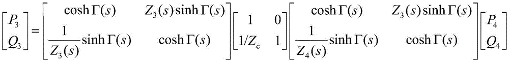
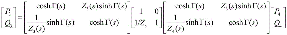
本发明提供了一种面向数字阀组压力脉动的复合型衰减装置,其包括颈部连接件、衬里腔体组件和HQ管组件,所述衬里腔体组件通过颈部连接件和所述HQ管组件连接;所述衬里腔体组件,其包括组合垫圈、衬里腔体内衬、衬里腔体外壳和衬里腔体顶盖,所述颈部连接件的第一安装端通过组合垫圈和所述衬里腔体外壳的第一安装端连接,所述衬里腔体内衬的安装端和所述衬里腔体外壳的第二安装端连接,所述衬里腔体顶盖的安装端和所述衬里腔体外壳的第三安装端连接;所述HQ管组件,其包括第一三通管接头、第二三通管接头、第三三通管接头、第一无缝钢管、第二无缝钢管、第三无缝钢管、第一焊接管、第二焊接管、第一弯头和第二弯头,所述颈部连接件的第二安装端和第一三通管接头的第一端连接,所述第一三通管接头的第二端通过第二无缝钢管和第二三通管接头的第一端连接,所述第二三通管接头的第二端通过第一焊接管和第一弯头的第一端连接,所述第一弯头的第二端通过第三无缝钢管和第二弯头的第一端连接,所述第二弯头的第二端通过第二焊接管和第三三通管接头的第一端连接,所述第三三通管接头的第二端通过第一无缝钢管和所述第一三通管接头的第三端连接;所述第一三通管接头、所述第一无缝钢管、所述第二无缝钢管、所述第二三通管接头和所述第三三通管接头组成主管路,所述主管路的传递矩阵数学模型表达式为:The invention provides a composite attenuation device for pressure pulsation of a digital valve group, which includes a neck connection piece, a lining cavity assembly and an HQ pipe assembly, and the liner cavity assembly passes through the neck connection piece and the HQ pipe Component connection; the liner cavity assembly, which includes a combination gasket, a liner cavity inner liner, a liner cavity shell and a liner cavity top cover, the first mounting end of the neck connector passes through the combination gasket and the liner The first installation end of the cavity shell is connected, the installation end of the liner cavity inner liner is connected with the second installation end of the liner cavity shell, the installation end of the liner cavity top cover is connected to the liner cavity The third installation end of the shell is connected; the HQ pipe assembly includes the first three-way pipe joint, the second three-way pipe joint, the third three-way pipe joint, the first seamless steel pipe, the second seamless steel pipe, the first Three seamless steel pipes, a first welded pipe, a second welded pipe, a first elbow and a second elbow, the second installation end of the neck connector is connected to the first end of the first three-way pipe joint, so The second end of the first three-way pipe joint is connected through the second seamless steel pipe and the first end of the second three-way pipe joint, and the second end of the second three-way pipe joint is connected through the first welded pipe and the first The first end of the elbow is connected, the second end of the first elbow is connected through the third seamless steel pipe and the first end of the second elbow, and the second end of the second elbow is connected through the second welded pipe It is connected with the first end of the third three-way pipe joint, and the second end of the third three-way pipe joint is connected with the third end of the first three-way pipe joint through the first seamless steel pipe; the first The three-way pipe joint, the first seamless steel pipe, the second seamless steel pipe, the second three-way pipe joint and the third three-way pipe joint form a main pipeline, and the transfer matrix of the main pipeline is mathematical The model expression is:
简化为:Simplifies to:
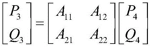
其中,P3为第三截面处的脉动压力,Q3为第三截面处的流量,P4为第四截面处的脉动压力,Q4为第四截面处的流量,Γ(s)为等截面管路单元的传播算子,Z3(s)为基本单元b的特征阻抗,Z4(s)为基本单元e的特征阻抗,A11,A12,A21,A22为主管路的四端参数;Among them, P 3 is the pulsating pressure at the third section, Q 3 is the flow rate at the third section, P 4 is the pulsating pressure at the fourth section, Q 4 is the flow rate at the fourth section, Γ(s) is equal to The propagation operator of the cross-section pipeline unit, Z 3 (s) is the characteristic impedance of the basic unit b, Z 4 (s) is the characteristic impedance of the basic unit e, A 11 , A 12 , A 21 , A 22 are the characteristic impedance of the main pipeline four terminal parameters;
所述第一焊接管、所述第一弯头、所述第二弯头、所述第三无缝钢管和所述第二焊接管组成辅助管路,所述辅助管路的传递矩阵数学模型表达式为:The first welded pipe, the first elbow, the second elbow, the third seamless steel pipe and the second welded pipe form an auxiliary pipeline, and the transfer matrix mathematical model of the auxiliary pipeline The expression is:
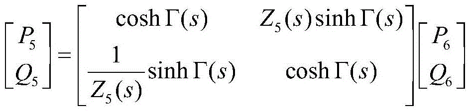
其中,P5为第五截面处的脉动压力,P6为第六截面处的脉动压力,Q5为第五截面处的流量,Q6为第六截面处的流量,Γ(s)为等截面管路单元的传播算子,Z5(s)为基本单元g的特征阻抗;Among them, P 5 is the pulsating pressure at the fifth section, P 6 is the pulsating pressure at the sixth section, Q 5 is the flow at the fifth section, Q 6 is the flow at the sixth section, Γ(s) is equal to The propagation operator of the cross-section pipeline unit, Z 5 (s) is the characteristic impedance of the basic unit g;
复合型衰减装置的传递矩阵数学模型表达式为:The mathematical model expression of the transfer matrix of the composite attenuation device is:

其中,in,

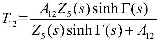

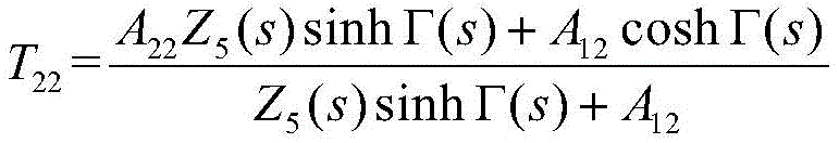
其中,Z5(s)为基本单元g的特征阻抗,Γ(s)为等截面管路单元的传播算子,P1为第一截面处的脉动压力,Q1为第一截面处的流量,P2为第二截面处的脉动压力,Q2为第二截面处的流量,T11,T12,T21和T22分别为复合型衰减装置中四端的参数,A11,A12,A21,A22为主管路的四端参数。Among them, Z 5 (s) is the characteristic impedance of the basic unit g, Γ(s) is the propagation operator of the equal-section pipeline unit, P 1 is the pulsating pressure at the first section, and Q 1 is the flow rate at the first section , P 2 is the pulsating pressure at the second section, Q 2 is the flow rate at the second section, T 11 , T 12 , T 21 and T 22 are the parameters of the four terminals in the composite damping device, A 11 , A 12 , A 21 and A 22 are the four-terminal parameters of the main pipeline.
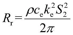
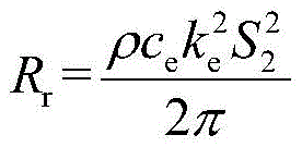
可优选的是,根据衬里腔体组件的组成结构,建立衬里腔体组件的等效模型,将衬里腔体组件依次等效为等效电阻、等效电感和等效电容,所述等效电阻,其包括辐射电阻和粘性电阻,所述辐射电阻的表达式为:Preferably, according to the composition structure of the lining cavity component, an equivalent model of the lining cavity component is established, and the lining cavity component is equivalent to equivalent resistance, equivalent inductance and equivalent capacitance in sequence, and the equivalent resistance , which includes radiation resistance and viscous resistance, the expression of the radiation resistance is:

其中,Rr为辐射电阻,ce为衬里腔体组件的有效速度,ke为衬里腔体组件的有效波数,ρ为材料密度,S2为颈部连接件的截面积;where R r is the radiation resistance, c e is the effective velocity of the lining cavity assembly, k e is the effective wave number of the lining cavity assembly, ρ is the material density, and S is the cross-sectional area of the neck connector;
所述粘性电阻的表达式为:The expression of the viscous resistance is:
Rw=2m2ωαw R w =2m 2 ωα w
其中,Rw为粘性电阻,αw为复波数的损失因子,m2为颈部连接件中油液的等效质量,ω为角频率;Among them, R w is the viscous resistance, α w is the loss factor of complex wave number, m 2 is the equivalent mass of oil in the neck connector, and ω is the angular frequency;
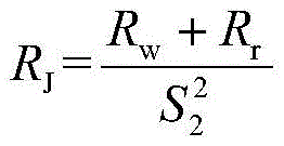
等效电阻的表达式为:The expression of equivalent resistance is:
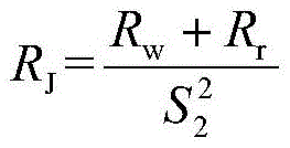
其中,RJ为等效电阻,Rr为辐射电阻,Rw粘性电阻,S2为颈部连接件的截面积;Among them, RJ is the equivalent resistance, Rr is the radiation resistance, Rw is the viscous resistance, and S2 is the cross-sectional area of the neck connector;
等效电感由颈部连接件的油液造成,颈部连接件中油液的等效质量表达式为:The equivalent inductance is caused by the oil in the neck connector, and the equivalent mass expression of the oil in the neck connector is:
m2=ρS2L'2 m 2 =ρS 2 L' 2
其中,m2为颈部连接件中油液的等效质量,ρ为材料密度,L2'为颈部连接件的等效长度,S2为颈部连接件的截面积;Among them, m 2 is the equivalent mass of oil in the neck connector, ρ is the material density, L 2 ' is the equivalent length of the neck connector, S 2 is the cross-sectional area of the neck connector;
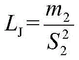
等效电感的表达式为:The expression for the equivalent inductance is:

其中,LJ为等效电感,m2为颈部连接件中油液的等效质量,S2为颈部连接件的截面积;Among them, L J is the equivalent inductance, m 2 is the equivalent mass of oil in the neck connector, and S 2 is the cross-sectional area of the neck connector;
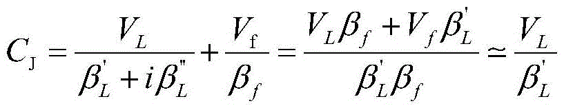
等效电容的表达式为:The expression for the equivalent capacitance is:
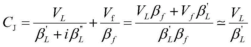
其中,CJ为等效电容,VL为衬里腔体内衬的体积,Vf为结构中液压油的体积,βL'为衬里腔体内衬的储能模量,βL”为衬里腔体内衬的耗散模量,βf为液压油的体积模量。Among them, C J is the equivalent capacitance, V L is the volume of the inner lining of the lining cavity, V f is the volume of hydraulic oil in the structure, β L ' is the storage modulus of the inner lining of the lining cavity, and β L ” is the lining The dissipation modulus of the cavity lining, βf is the bulk modulus of the hydraulic oil.
可优选的是,在所述HQ管组件中,根据复合型衰减装置的传递矩阵数学模型,将第三三通管接头的安装位置设为基本单元a,第一无缝钢管的安装位置设为基本单元b,第一三通管接头的安装位置设为基本单元c,衬里腔体组件的腔体结构设为基本单元d,第二无缝钢管的安装位置设为基本单元e,第二三通管接头的安装位置设为基本单元f,HQ管组件中辅助管路的安装位置设为基本单元g。Preferably, in the HQ pipe assembly, according to the mathematical model of the transfer matrix of the composite attenuation device, the installation position of the third three-way pipe joint is set as the basic unit a, and the installation position of the first seamless steel pipe is set as Basic unit b, the installation position of the first three-way pipe joint is set as basic unit c, the cavity structure of the lining cavity assembly is set as basic unit d, the installation position of the second seamless steel pipe is set as basic unit e, the second three The installation position of the pipe joint is set as the basic unit f, and the installation position of the auxiliary pipeline in the HQ pipe assembly is set as the basic unit g.
可优选的是,所述基本单元b的传递矩阵数学模型为:Preferably, the mathematical model of the transfer matrix of the basic unit b is:

所述基本单元e的传递矩阵数学模型为:The transfer matrix mathematical model of the basic unit e is:

所述基本单元g的传递矩阵数学模型为:The transfer matrix mathematical model of the basic unit g is:
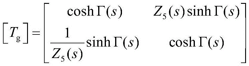
其中,Z3(s)为基本单元b的特征阻抗,Z4(s)为基本单元e的特征阻抗,Z5(s)为基本单元g的特征阻抗,Γ(s)为等截面管路单元的传播算子。Among them, Z 3 (s) is the characteristic impedance of the basic unit b, Z 4 (s) is the characteristic impedance of the basic unit e, Z 5 (s) is the characteristic impedance of the basic unit g, Γ(s) is the equal-section pipeline The spread operator for the unit.
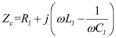
可优选的是,所述基本单元c的传递矩阵数学模型分别为:Preferably, the mathematical models of the transfer matrix of the basic unit c are respectively:

其中,Zc为衬里腔体组件部分的系统阻抗。Among them, Z c is the system impedance of the lined cavity assembly part.
本发明的第二方面,提供一种用于前述面向数字阀组压力脉动的复合型衰减装置的测试方法,其包括以下步骤:The second aspect of the present invention provides a test method for the composite damping device for pressure pulsation of the aforementioned digital valve group, which includes the following steps:
S1、将变频电机的输出端和液压泵的控制端连接,将变频电机的控制端和控制器输出端连接,并将溢流阀并联在液压泵一侧,将第一数字阀和第二数字阀并联组成数字阀组,并将数字阀组驱动板的输入端分别与第一数字阀和第二数字阀的控制端连接;S1. Connect the output terminal of the variable frequency motor to the control terminal of the hydraulic pump, connect the control terminal of the variable frequency motor to the output terminal of the controller, and connect the overflow valve to the side of the hydraulic pump in parallel, and connect the first digital valve to the second digital valve. The valves are connected in parallel to form a digital valve group, and the input ends of the digital valve group drive board are respectively connected to the control ends of the first digital valve and the second digital valve;
S2、将液压泵的供油口串联第一压力传感器并且和数字阀组的第一端连接,将数字阀组的第二端和复合型衰减装置中第三三通管接头的第三安装端连接,将复合型衰减装置中第二三通管接头的第三安装端串联第二压力传感器并且依次与流量传感器、流量控制阀和油箱连接;S2. Connect the oil supply port of the hydraulic pump to the first pressure sensor in series and connect it to the first end of the digital valve group, and connect the second end of the digital valve group to the third installation end of the third three-way pipe joint in the composite attenuation device Connecting, connecting the third installation end of the second three-way pipe joint in the composite attenuation device in series with the second pressure sensor and connecting it with the flow sensor, the flow control valve and the oil tank in sequence;
S3、将数字阀组驱动板、第一压力传感器、第二压力传感器和流量传感器采集的信息通过采集板卡传输给控制器。S3. The information collected by the digital valve group driver board, the first pressure sensor, the second pressure sensor and the flow sensor is transmitted to the controller through the collection board.
可优选的是,所述变频电机、所述溢流阀和所述液压泵组成液压动力回路;所述第一数字阀、所述第二数字阀、所述复合型衰减装置、所述流量控制阀、所述第一压力传感器、所述第二压力传感器和所述流量传感器组成试验测试回路;所述控制器、所述采集板卡和所述数字阀组驱动板组成控制采集回路。Preferably, the variable frequency motor, the overflow valve and the hydraulic pump form a hydraulic power circuit; the first digital valve, the second digital valve, the composite attenuation device, the flow control The valve, the first pressure sensor, the second pressure sensor and the flow sensor form a test loop; the controller, the acquisition board and the digital valve group drive board form a control acquisition loop.
本发明与现有技术相比,具有如下优点:Compared with the prior art, the present invention has the following advantages:
1.本发明利用衬里腔体组件及由并联的数字阀产生压力波的相位相错振幅相消进行双重滤波,将共振型压力脉动与干涉型压力脉动相结合,使其适用于数字阀组在低频压力脉动的复合型衰减装置,从而减小数字阀在开关控制过程中引起的压力脉动,提高数字阀的寿命。1. The present invention uses the liner cavity assembly and the phase-staggered amplitude cancellation of the pressure wave generated by the parallel digital valve to perform double filtering, and combines the resonance-type pressure pulsation with the interference-type pressure pulsation, making it suitable for digital valve groups in The composite attenuation device of low-frequency pressure pulsation reduces the pressure pulsation caused by the digital valve during the switch control process and improves the life of the digital valve.
2.本发明通过抑制振动与噪声,有利于提升数字阀的控制性能,从而提高数字阀的寿命和数字阀控系统性能,同时该面向数字阀组的压力脉动测量方法,能提高测量的准确性,有利于探究影响数字阀组压力脉动的相关机制。2. The present invention is conducive to improving the control performance of the digital valve by suppressing vibration and noise, thereby improving the life of the digital valve and the performance of the digital valve control system. At the same time, the pressure pulsation measurement method for the digital valve group can improve the accuracy of the measurement , which is conducive to exploring the relevant mechanism affecting the pressure pulsation of the digital valve group.
附图说明Description of drawings
图1为本发明面向数字阀组压力脉动的复合型衰减装置的工作原理图;Fig. 1 is the working principle diagram of the composite attenuation device facing the digital valve group pressure pulsation according to the present invention;
图2为本发明面向数字阀组压力脉动的复合型衰减装置的结构示意图;Fig. 2 is a structural schematic diagram of a composite attenuation device for digital valve group pressure pulsation according to the present invention;
图3为本发明面向数字阀组压力脉动的复合型衰减装置中颈部连接件和衬里腔体组件的结构图;Fig. 3 is a structural diagram of the neck connector and the lining cavity assembly in the composite attenuation device facing digital valve group pressure pulsation according to the present invention;
图4为本发明面向数字阀组压力脉动的复合型衰减装置中HQ组件的结构图;Fig. 4 is the structural diagram of the HQ assembly in the complex attenuation device facing digital valve group pressure pulsation according to the present invention;
图5为本发明面向数字阀组压力脉动的复合型衰减装置的测试方法的测试原理图;Fig. 5 is the test schematic diagram of the test method of the compound type attenuation device facing digital valve group pressure pulsation according to the present invention;
图6为本发明面向数字阀组压力脉动的复合型衰减装置的测试方法在不同负载端压力及脉动频率下的插入损失图;Fig. 6 is the insertion loss diagram under different load end pressures and pulsation frequencies of the test method of the composite attenuation device for digital valve group pressure pulsation according to the present invention;
图7为本发明面向数字阀组压力脉动的复合型衰减装置的测试方法在不同衬里腔体内衬体积模量及脉动频率下的插入损失图;Fig. 7 is a diagram of the insertion loss of the test method of the composite attenuation device facing digital valve group pressure pulsation under different lining cavity lining bulk modulus and pulsation frequency of the present invention;
图8为本发明面向数字阀组压力脉动的复合型衰减装置的测试方法在不同颈部直径及脉动频率下的插入损失图。Fig. 8 is a graph of insertion loss under different neck diameters and pulsation frequencies of the test method of the composite attenuation device for digital valve group pressure pulsation according to the present invention.
主要附图标记:Main reference signs:
颈部连接件1,衬里腔体组件2,HQ管(Herschel-Quincke管)组件3,第一三通管接头4,组合垫圈5,衬里腔体内衬6,衬里腔体外壳7,衬里腔体顶盖8,第一无缝钢管9,第二无缝钢管10,第二三通管接头11,第一焊接管12,第一弯头13,第二弯头14,第三无缝钢管15,第二焊接管16,第三三通管接头17,变频电机18,第一压力传感器19,第一数字阀20,第二数字阀21,数字阀组驱动板22,复合型衰减装置23,流量传感器24,流量控制阀25,控制器26,采集板卡27,第二压力传感器28,溢流阀29。
具体实施方式Detailed ways
为详尽本发明之技术内容、结构特征、所达成目的及功效,以下将结合说明书附图进行详细说明。In order to detail the technical content, structural features, achieved goals and effects of the present invention, the following will be described in detail in conjunction with the accompanying drawings.
利用衬里腔体组件2及由并联的数字阀产生压力波的相位相错振幅相消进行双重滤波,将共振型压力脉动与干涉型压力脉动相结合,提出一种面向数字阀组压力脉动的复合型衰减装置,如图1、图3和图4所示,包括颈部连接件1、衬里腔体组件2和HQ管组件3,衬里腔体组件2通过颈部连接件1和HQ管组件3连接。Using the
衬里腔体组件2采用的是分体式结构,分体式的结构便于调整与安装,同时能够降低价格成本提高加工精度,如图2所示,具体包括组合垫圈5、衬里腔体内衬6、衬里腔体外壳7和衬里腔体顶盖8,颈部连接件1的第一安装端通过组合垫圈5和衬里腔体外壳7的第一安装端螺纹连接,组合垫圈5保证在该种连接方式下不漏油,衬里腔体内衬6的安装端通过硫化的方式粘连在衬里腔体外壳7的第二安装端,衬里腔体顶盖8的安装端通过螺纹和衬里腔体外壳7的第三安装端连接,中间加装ED垫圈保证在该种连接方式下不漏油。The lining
在液压系统中,颈部连接件1中的油液介质可以看作一个具有相应质量的小液柱,当脉动压力作用于小液柱上时,小液柱类似活塞进行往复运动,衬里腔体组件2类似于质量-弹簧-阻尼系统,小液柱等效为质量,衬里腔体组件2的腔体结构d等效为弹簧,衬里腔体组件2的腔体结构d的阻尼和摩擦等效为阻尼。In the hydraulic system, the oil medium in the
具体而言,复合型衰减装置23利用衬里腔体组件2及由并联的数字阀产生压力波的相位相错振幅相消进行双重滤波,根据衬里腔体组件2的组成结构,建立衬里腔体组件2的等效模型,将衬里腔体组件2依次等效为等效电阻、等效电感和等效电容,等效电阻,由辐射电阻和粘性电阻组成,辐射电阻的表达式为:Specifically, the
其中,Rr为辐射电阻,ce为衬里腔体组件2的有效速度,ke为衬里腔体组件2的有效波数,ρ为材料密度,S2为颈部连接件1的截面积。where R r is the radiation resistance, c e is the effective velocity of the
粘性电阻的表达式为:The expression for viscous resistance is:
Rw=2m2ωαw R w =2m 2 ωα w
其中,Rw为粘性电阻,αw为复波数的损失因子,m2为颈部连接件1中油液的等效质量,ω为角频率。Among them, R w is the viscous resistance, α w is the loss factor of complex wave number, m 2 is the equivalent mass of oil in the
由此可得,等效电阻的表达式为:It can be obtained that the expression of the equivalent resistance is:

其中,RJ为等效电阻,Rr为辐射电阻,Rw为粘性电阻,S2为颈部连接件1的截面积。Among them, RJ is the equivalent resistance, Rr is the radiation resistance, Rw is the viscous resistance, and S2 is the cross-sectional area of the
衬里腔体内衬6的特征阻抗表达式为:The characteristic impedance expression of the
其中,Zc为衬里腔体组件2的系统阻抗,RJ为等效电阻,LJ为等效电感,ω为角频率。Wherein, Z c is the system impedance of the
等效电感由颈部连接件1的油液造成,颈部连接件1中油液的等效质量表达式为:The equivalent inductance is caused by the oil in the
m2=ρS2L'2 m 2 =ρS 2 L' 2
其中,m2为颈部连接件1中油液的等效质量,ρ为材料密度,L2'为颈部连接件1的等效长度,S2为颈部连接件1的截面积。Among them, m 2 is the equivalent mass of oil in the
等效电感的表达式为:The expression for the equivalent inductance is:
其中,LJ为等效电感,m2为颈部连接件1中油液的等效质量,S2为颈部连接件1的截面积。Among them, L J is the equivalent inductance, m 2 is the equivalent mass of oil in the
等效电容是由衬里腔体组件2的腔体结构中的油液及衬里腔体内衬6的容性造成,等效电容的表达式为:The equivalent capacitance is caused by the oil in the cavity structure of the
其中,CJ为等效电容,VL为衬里腔体内衬6的体积,Vf为衬里腔体内衬6中液压油的体积,βL'为衬里腔体内衬6的储能模量,βL”为衬里腔体内衬6的耗散模量,βf为液压油的体积模量。Among them, C J is the equivalent capacitance, V L is the volume of the
本发明采用传递损失的方法对压力脉动抑制效果进行评价,传递损失(Transmission Loss,TL)为压力脉动复合型衰减装置23应用声学消声器的声学性能评价指标。传递损失在声学之中定义为出口无反射端时,消声器的进口处的入射声功率级与出口处的声功率级之差;The present invention adopts the transmission loss method to evaluate the pressure pulsation suppression effect, and the transmission loss (Transmission Loss, TL) is the acoustic performance evaluation index of the pressure pulsation
在具有消声终端的理想液压系统中,对于具有四端参数传递矩阵数学模型的压力脉动复合型衰减装置23,其传输损失表达式由传输矩阵数学模型的四端参数计算求解,具体表达式如下:In an ideal hydraulic system with a muffler terminal, for a pressure
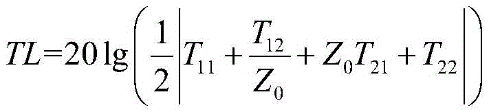
其中,Z0(s)为HQ管组件3中等截面管路单元的特征阻抗,T11,T12,T21和T22分别为复合型衰减装置23中的四端参数。Among them, Z 0 (s) is the characteristic impedance of the medium-section pipeline unit of the
在本发明的一个优选实施中,衬里腔体组件2结构部分的衬里腔体内衬6的长度L1会影响等效电容,进一步影响复合型衰减装置23的衰减效果,因此,需要对衬里腔体内衬6的长度L1影响压力脉动衰减效果进行分析,首先给定除衬里腔体内衬6的长度L1外的其它参数为定值,分别取不同衬里腔体内衬6的长度L1,将不同的衬里腔体内衬6的长度L1代入上述等效电容表达式,再将复合型衰减装置23的传递矩阵数学模型代入上述传输损失表达式,由此可得:衬里腔体组件2的长度L1越长衰减效果越好且有效工作频率范围越高;而且衬里腔体组件2长度对于复合型衰减装置23的有效工作频率范围及传递损失幅值影响效果适中。In a preferred implementation of the present invention, the length L1 of the
衬里腔体组件2结构部分的衬里腔体内衬6的体积模量βL会影响等效电容,进一步影响复合型衰减装置23的衰减效果,因此需要对衬里腔体内衬6体积模量影响压力脉动衰减效果进行分析,给定除衬里腔体内衬6体积模量外的其他参数为定值,分别取不同衬里腔体内衬6体积模量βL,将不同的衬里腔体内衬6体积模量βL代入等效电容表达式,再将复合型衰减装置23的传递矩阵数学模型代入上述传输损失表达式。由此可得:随着衬里腔体内衬6体积模量增加,复合型衰减装置23的有效工作频率范围减少,同时传递损失幅值有所降低;而且衬里腔体内衬6体积模量对于复合型衰减装置23的有效工作频率范围和传递损失幅值影响较为明显。The bulk modulus β L of the lining cavity lining 6 of the
颈部连接件1因其具备的感性与阻性会对数字阀组低频工况的压力脉动衰减效果产生较大影响。The
由于颈部连接件1长度L2会影响等效电感及等效电阻,进一步影响复合型衰减装置23的衰减效果,因此需要对颈部连接件1长度影响压力脉动衰减效果进行分析,给定除颈部连接件1长度外的其他参数为定值。分别取不同颈部连接件1长度L2,将不同的颈部连接件1长度L2代入上述颈部连接件1等效质量表达式,再将复合型衰减装置23的传递矩阵数学模型代入上述传输损失表达式,由此可得:随着颈部长度L2增加,复合型衰减装置23的有效工作频率范围降低,同时传递损失幅值降低;而且颈部长度L2对于复合型衰减装置23的有效工作频率范围及传递损失幅值影响适中。Since the length L of the
由于颈部连接件1直径d2会影响等效电感及等效电阻,进一步影响复合型衰减装置23的衰减效果,因此需要对颈部连接件1直径d2影响压力脉动衰减效果进行分析,首先给定除颈部连接件1直径d2外的其他参数为定值,分别取不同颈部连接件1直径d2。将不同的颈部连接件1直径d2代入上述颈部等效质量表达式中,再将复合型衰减装置23的传递矩阵数学模型代入上述传输损失表达式中,由此可得:随着颈部直径增加复合型衰减装置23的有效工作频率范围增加,同时传递损失增加,而且颈部直径d2对于复合型衰减装置23的有效工作频率范围及传递损失幅值影响较大。Since the diameter d2 of the
HQ管组件3,如图4所示,包括第一三通管接头4、第一无缝钢管9、第二无缝钢管10、第二三通管接头11、第一焊接管12、第一弯头13、第二弯头14、第三无缝钢管15、第二焊接管16和第三三通管接头17,颈部连接件1的第二安装端和第一三通管接头4的第一端连接,第一三通管接头4的第二端通过第二无缝钢管10和第二三通管接头11的第一端连接,第二三通管接头11的第二端通过第一焊接管12和第一弯头13的第一端连接,第一弯头13的第二端通过第三无缝钢管15和第二弯头14的第一端连接,第二弯头14的第二端通过第二焊接管16和第三三通管接头17的第一端连接,第三三通管接头17的第二端通过第一无缝钢管9和第一三通管接头4的第三端连接。HQ管组件3的连接方式能够较为方便的调整在装配过程中出现的尺寸误差,提高整体样机装配的容错率。
具体而言,应用液电比拟法构建出复合型衰减装置23的整体传递矩阵数学模型,并将其划分为基本单元,如图2所示,将第三三通管接头17的安装位置设为基本单元a,第一无缝钢管9的安装位置设为基本单元b,第一三通管接头4的安装位置设为基本单元c,衬里腔体组件2的腔体结构设为基本单元d,第二无缝钢管10的安装位置设为基本单元e,基本单元b、基本单元e和基本单元g均为等截面管路单元,第二三通管接头11的安装位置设为基本单元f,HQ管组件3中辅助管路的安装位置设为基本单元g。Specifically, the mathematical model of the overall transfer matrix of the
基本单元b的传递矩阵数学模型为:The mathematical model of the transfer matrix of the basic unit b is:

基本单元e的传递矩阵数学模型为:The mathematical model of the transfer matrix of the basic unit e is:

基本单元g的传递矩阵数学模型为:The mathematical model of the transfer matrix of the basic unit g is:

其中,Z3(s)为基本单元b的特征阻抗,Z4(s)为基本单元e的特征阻抗,Z5(s)为基本单元g的特征阻抗,Γ(s)为等截面管路单元的传播算子。Among them, Z 3 (s) is the characteristic impedance of the basic unit b, Z 4 (s) is the characteristic impedance of the basic unit e, Z 5 (s) is the characteristic impedance of the basic unit g, Γ(s) is the equal-section pipeline The spread operator for the unit.
基本单元c的传递矩阵数学模型分别为:The mathematical models of the transfer matrix of the basic unit c are:
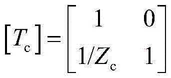
其中,Zc为衬里腔体组件2的系统阻抗。Wherein, Z c is the system impedance of the
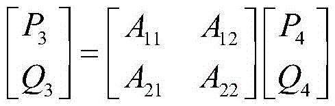
HQ管组件3是由主管路及辅助管路并联组成,管路在第一个分支处形成两条管路,在第二个分支处又合并为一条;HQ管组件3中两个管路的长度的差异产生了相位差,两列压力波在第二个分支处“相互干涉”实现了衰减压力脉动的效果。第一三通管接头4、第一无缝钢管9、第二无缝钢管10、第二三通管接头11和第三三通管接头17组成主管路,主管路的传递矩阵数学模型表达式为:The
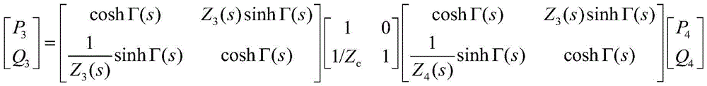
可以简化为:can be simplified to:

其中,P3为第三截面处的脉动压力,Q3为第三截面处的流量,P4为第四截面处的脉动压力,Q4为第四截面处的流量,Γ(s)为等截面管路单元的传播算子,Z3(s)为基本单元b的特征阻抗,Z4(s)为基本单元e的特征阻。Among them, P 3 is the pulsating pressure at the third section, Q 3 is the flow rate at the third section, P 4 is the pulsating pressure at the fourth section, Q 4 is the flow rate at the fourth section, Γ(s) is equal to The propagation operator of the cross-section pipeline unit, Z 3 (s) is the characteristic impedance of the basic unit b, and Z 4 (s) is the characteristic impedance of the basic unit e.
第一焊接管12、第一弯头13、第二弯头14、第三无缝钢管15和第二焊接管16组成辅助管路,辅助管路的传递矩阵数学模型表达式为:The first welded
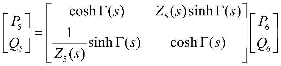
其中,P5为第五截面处的脉动压力,P6为第六截面处的脉动压力,Q5为第五截面处的流量,Q6为第六截面处的流量,Γ(s)为等截面管路单元的传播算子,Z5(s)为基本单元g的特征阻抗。Among them, P 5 is the pulsating pressure at the fifth section, P 6 is the pulsating pressure at the sixth section, Q 5 is the flow at the fifth section, Q 6 is the flow at the sixth section, Γ(s) is equal to The propagation operator of the section pipeline unit, Z 5 (s) is the characteristic impedance of the basic unit g.
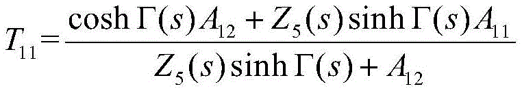
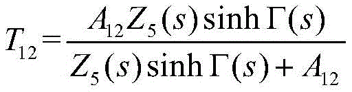
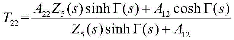
复合型衰减装置23的传递矩阵数学模型表达式为:The transfer matrix mathematical model expression of

其中,in,
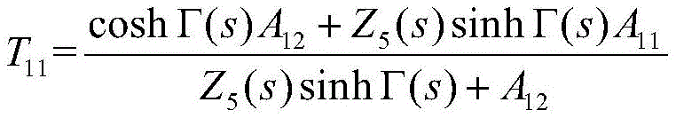
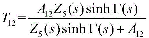
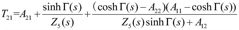

其中,Z5(s)为基本单元g的特征阻抗,Γ(s)为等截面管路单元的传播算子,P1为第一截面处的脉动压力,Q1为第一截面处的流量,P2为第二截面处的脉动压力,Q2为第二截面处的流量,T11,T12,T21和T22分别为复合型衰减装置中四端的参数。Among them, Z 5 (s) is the characteristic impedance of the basic unit g, Γ(s) is the propagation operator of the equal-section pipeline unit, P 1 is the pulsating pressure at the first section, and Q 1 is the flow rate at the first section , P 2 is the pulsating pressure at the second section, Q 2 is the flow rate at the second section, T 11 , T 12 , T 21 and T 22 are the parameters of the four terminals in the composite attenuation device.
具体而言,通过变频电机18改变液压泵的转速和排量,溢流阀29主要为限压作用,用作安全阀保护液压系统安全工作,同时溢流阀29在液压泵口调节数字阀组之前的压力,液压泵为整个液压系统提供具备恒定压力的油液,液压泵的进油口从油箱吸取流体介质,为液压系统提供一定流量和压力的流体介质,流体介质通过数字阀组产生压力脉动,数字阀组对于不同的PWM信号输入会制造出不同压力脉动,复合型衰减装置23通过钢直管接入液压系统,在流体介质流经复合型衰减装置23,经过压力传感器与流量传感器24,通过流量控制阀25流回油箱,流量控制阀25采用手动控制节流阀,可以调节负载端的压力,从而可以模拟复合型衰减装置23样机负载端压力的变化,控制器以及采集板卡27通过CAN总线相连实现实时的数据传输,同时二者协同作用实现控制数字阀组驱动板22以及采集第二压力传感器28、流量传感器24数据的功能。Specifically, the speed and displacement of the hydraulic pump are changed by the
变频电机18、溢流阀29和液压泵组成液压动力回路,液压泵通过CAN总线的方式与上机位相连能够对移动油源进行状态监测,并且实时的改变移动油源最高输出压力、最大输出流量等参数;第一数字阀20、第二数字阀21、复合型衰减装置23、流量控制阀25、第一压力传感器19、第二压力传感器28和流量传感器24组成,试验测试回路既确保了实验的合理性,又最大限度的确保了对于压力脉动测量的准确性;控制器、采集板卡27和数字阀组驱动板22组成控制采集回路,控制采集回路的电控部分主要负责数字阀组驱动板22的电信号输入及压力、流量传感器24的数据采集。
以下结合实施例对本发明一种面向数字阀组压力脉动的复合型衰减装置及测试方法做进一步描述:A composite attenuation device and testing method for digital valve group pressure pulsation of the present invention will be further described in conjunction with the following examples:
根据复合型衰减装置23中衬里腔体组件2的结构特性,在本具体实施例中,将衬里腔体外壳7的外径D1设为59mm,主管路直径dp设为10mm,同时在保证结构耐压等级要求的前提下(按工程设计中的经验对结构的壁厚进行初步计算),得到衬里腔体组件2中腔体结构最大体积约为0.4L。According to the structural characteristics of the
同时为适用于数字阀组在低频工况的压力脉动,将衬里腔体组件2的体积模量βL≤20MPa;根据HQ管组件3的整体外形尺寸、管路接口尺寸与预留合适的工程安装空间尺寸限制,将颈部连接件1的长度控制在50mm≤L2≤60mm,颈部连接件1的直径控制在d2≤10mm,具体而言,颈部连接件1长度L2越小,颈部连接件1直径d2越大,衬里腔体组件2结构部分的工作频率范围越高。不过随着颈部连接件1长度L2的升高与颈部连接件1直径d2的降低,整体工作频率越能适用于数字阀组低频工况的压力脉动,但压力脉动衰减效果越差,因此,在结合工程实际情况的前提下选用颈部连接件1长度L2为50mm,同时设计三种颈部连接件1直径d2分别为6mm、8mm和10mm。At the same time, in order to be suitable for the pressure pulsation of the digital valve group in low-frequency working conditions, the bulk modulus of the
由于HQ管组件3的结构参数对于压力脉动的衰减效果影响较为明显,设定HQ管组件3(是无缝钢管还是焊接管,对应一下)直径d5及长度l5边界条件为:
在本实施中面向数字阀组压力脉动的复合型衰减装置的测试方法,如图5所示,包括以下步骤:In this implementation, the test method for the composite attenuation device for the pressure pulsation of the digital valve group, as shown in Figure 5, includes the following steps:
S1、将变频电机18的输出端和液压泵的控制端连接,将变频电机18的控制端和控制器输出端连接,并将溢流阀29并联在液压泵一侧,将第一数字阀20和第二数字阀21并联组成数字阀组,数字阀组是压力脉动源,对于不同的PWM信号输入会制造出不同压力脉动,再将压力脉动传递给复合型衰减装置23,数字阀通过盖板安装在数字阀组的阀体上,其上方通过电磁线圈的方式进行驱动,并将数字阀组驱动板22的输入端分别与第一数字阀20和第二数字阀21的控制端连接。S1. Connect the output terminal of the
S2、将液压泵的供油口串联第一压力传感器19并且和数字阀组的第一端连接,将数字阀组的第二端和复合型衰减装置23中第三三通管接头17的第三安装端连接,将复合型衰减装置23中第二三通管接头11的第三安装端串联第二压力传感器28并且依次与流量传感器24、流量控制阀25和油箱连接,使用磁力座将复合型衰减装置23固定在底板之上,保证其在测试的过程中处于固定状态;第二压力传感器28为电流型压力传感器,用来测试复合型衰减装置23在不同的工况下的压力响应曲线,并将数据采集到控制器的内置板卡中,流量传感器24为电压型传感器,通过采集板卡10进行采集,通过CAN通讯传输到控制器中,主要是测试液压系统回油路的流量数值,对应于数字阀组工作的过程中的负载端流量输入,流量控制阀25主要是起到模拟液压系统负载的作用,通过控制流量控制阀25的阀口开度大小控制负载端的压力。S2. Connect the oil supply port of the hydraulic pump to the
S3、将数字阀组驱动板22、第一压力传感器19、第二压力传感器28和流量传感器24采集的信息通过采集板卡27传输给控制器,控制器将采集的数据通过CAN总线传输到上位机的程序中,来调节整个液压系统的压力。S3. The information collected by the digital valve
在该测试方法中,液压泵提供一定流量和压力的流体介质,流体介质通过数字阀组产生压力脉动,在流经复合型衰减装置23,经过压力传感器与流量传感器24,通过流量控制阀25流回油箱,控制器及采集板卡27通过CAN总线相连实现实时的数据传输,同时二者协同作用实现控制数字阀组驱动板22及采集压力传感器和流量传感器数据,测得不同负载端压力(3MPa、4MPa、5MPa)及脉动频率下的插入损失图,如图6所示,不同衬里腔体内衬体积模量(10MPa、15MPa、20MPa)及脉动频率下的插入损失图,如图7所示,不同颈部直径(4mm、6mm、8mm)及脉动频率下的插入损失图,如图8所示。In this test method, the hydraulic pump provides a fluid medium with a certain flow rate and pressure. The fluid medium passes through the digital valve group to generate pressure pulsation, and then flows through the
以上所述的实施例仅是对本发明的优选实施方式进行描述,并非对本发明的范围进行限定,在不脱离本发明设计精神的前提下,本领域普通技术人员对本发明的技术方案做出的各种变形和改进,均应落入本发明权利要求书确定的保护范围内。The above-mentioned embodiments are only descriptions of preferred implementations of the present invention, and are not intended to limit the scope of the present invention. All such modifications and improvements should fall within the scope of protection defined by the claims of the present invention.
Claims (6)


Priority Applications (1)
| Application Number | Priority Date | Filing Date | Title |
|---|---|---|---|
| CN202210833653.2A CN115126739B (en) | 2022-07-14 | 2022-07-14 | Composite type attenuation device for digital valve group pressure pulsation and test method thereof |
Applications Claiming Priority (1)
| Application Number | Priority Date | Filing Date | Title |
|---|---|---|---|
| CN202210833653.2A CN115126739B (en) | 2022-07-14 | 2022-07-14 | Composite type attenuation device for digital valve group pressure pulsation and test method thereof |
Publications (2)
| Publication Number | Publication Date |
|---|---|
| CN115126739A CN115126739A (en) | 2022-09-30 |
| CN115126739B true CN115126739B (en) | 2023-03-31 |
Family
ID=83383926
Family Applications (1)
| Application Number | Title | Priority Date | Filing Date |
|---|---|---|---|
| CN202210833653.2A Active CN115126739B (en) | 2022-07-14 | 2022-07-14 | Composite type attenuation device for digital valve group pressure pulsation and test method thereof |
Country Status (1)
| Country | Link |
|---|---|
| CN (1) | CN115126739B (en) |
Family Cites Families (5)
| Publication number | Priority date | Publication date | Assignee | Title |
|---|---|---|---|---|
| JP2001141108A (en) * | 1999-11-18 | 2001-05-25 | Shin Caterpillar Mitsubishi Ltd | Valve appliance |
| CN105864189A (en) * | 2016-05-12 | 2016-08-17 | 绍兴文理学院 | Hydraulic wave filtering method for full-band variable structure |
| EP3548729B1 (en) * | 2016-11-29 | 2023-02-22 | Garrett Transportation I Inc. | An inferential flow sensor |
| CN110909510B (en) * | 2019-10-30 | 2021-11-23 | 北京航空航天大学 | Three-dimensional simulation method for pressure pulsation attenuator |
| CN114739614A (en) * | 2022-05-24 | 2022-07-12 | 华易航(苏州)航空科技有限公司 | Test device for testing pressure pulsation and vibration response of pipeline and test method thereof |
-
2022
- 2022-07-14 CN CN202210833653.2A patent/CN115126739B/en active Active
Also Published As
| Publication number | Publication date |
|---|---|
| CN115126739A (en) | 2022-09-30 |
Similar Documents
| Publication | Publication Date | Title |
|---|---|---|
| CN201508303U (en) | Hose pulse testing machine | |
| CN101801763B (en) | Duct provided with a device for absorption of pressure pulses | |
| CN103062569B (en) | A kind of Pressure-auto-balanchydrodynamic hydrodynamic noise silencer | |
| CN103115214B (en) | Wave absorbing device used for eliminating and reducing noise and pulses of hydraulic system fluid | |
| CN105257943A (en) | Hydraulic pipeline fluid pulsation attenuation device based on piezoelectric shunt damping technology | |
| US20120003106A1 (en) | Tunable choke tube for pulsation control device used with gas compressor | |
| CN201496347U (en) | Vibration-reducing muffler for broadband hydraulic system | |
| CN115288966B (en) | Method for suppressing fluid pressure pulsation of hydraulic pump | |
| CN101614231A (en) | Vibration-reducing muffler for hydraulic system with wide-spectrum filtering effect | |
| CN115126739B (en) | Composite type attenuation device for digital valve group pressure pulsation and test method thereof | |
| CN114077772A (en) | An intelligent control hydraulic system and a functional circuit simulation modeling method of the intelligent control hydraulic system | |
| CN101684765B (en) | Low-pressure oil way pressure stabilizing and distributing device of monoblock pump fuel oil system | |
| CN107461378A (en) | A kind of fluid pulsation decay Active Control Method compound based on stream is divided into | |
| CN101975326B (en) | Pipe type hydraulic fluid muffler | |
| CN102705043B (en) | Crane and silencer of crane exhaust system | |
| CN108593273B (en) | A low frequency-oriented pulsating pressure attenuation device and its performance testing method | |
| CN209977150U (en) | Vibration reduction structure of plunger pump | |
| CN104778366B (en) | A kind of computational methods of tubular porous H types hydraulic filter intrinsic frequency | |
| CN110107765B (en) | An adaptive compound pressure pulsation attenuator | |
| CN207363843U (en) | The buffer unit of combined filter | |
| CN219300202U (en) | Hydraulic pulsation attenuator, hydraulic system and engineering machinery | |
| CN105864209A (en) | Method for restraining pressure pulsation of hydraulic system | |
| CN105909598A (en) | Full-frequency-band hydraulic system pressure pulsating suppression device | |
| He et al. | The Performance Study of Current-Carrying Plate Fluid Attenuator | |
| CN212455058U (en) | Hydraulic pressure shaking table residual energy safety release |
Legal Events
| Date | Code | Title | Description |
|---|---|---|---|
| PB01 | Publication | ||
| PB01 | Publication | ||
| SE01 | Entry into force of request for substantive examination | ||
| SE01 | Entry into force of request for substantive examination | ||
| GR01 | Patent grant | ||
| GR01 | Patent grant |