CN115121809B - Curved generatrix conical surface lattice structure and additive manufacturing method and device thereof - Google Patents
Curved generatrix conical surface lattice structure and additive manufacturing method and device thereof Download PDFInfo
- Publication number
- CN115121809B CN115121809B CN202210784696.6A CN202210784696A CN115121809B CN 115121809 B CN115121809 B CN 115121809B CN 202210784696 A CN202210784696 A CN 202210784696A CN 115121809 B CN115121809 B CN 115121809B
- Authority
- CN
- China
- Prior art keywords
- layer
- lattice
- point
- additive manufacturing
- cell
- Prior art date
- Legal status (The legal status is an assumption and is not a legal conclusion. Google has not performed a legal analysis and makes no representation as to the accuracy of the status listed.)
- Active
Links
Images


Classifications
-
- B—PERFORMING OPERATIONS; TRANSPORTING
- B22—CASTING; POWDER METALLURGY
- B22F—WORKING METALLIC POWDER; MANUFACTURE OF ARTICLES FROM METALLIC POWDER; MAKING METALLIC POWDER; APPARATUS OR DEVICES SPECIALLY ADAPTED FOR METALLIC POWDER
- B22F10/00—Additive manufacturing of workpieces or articles from metallic powder
- B22F10/20—Direct sintering or melting
- B22F10/28—Powder bed fusion, e.g. selective laser melting [SLM] or electron beam melting [EBM]
-
- B—PERFORMING OPERATIONS; TRANSPORTING
- B22—CASTING; POWDER METALLURGY
- B22F—WORKING METALLIC POWDER; MANUFACTURE OF ARTICLES FROM METALLIC POWDER; MAKING METALLIC POWDER; APPARATUS OR DEVICES SPECIALLY ADAPTED FOR METALLIC POWDER
- B22F10/00—Additive manufacturing of workpieces or articles from metallic powder
- B22F10/80—Data acquisition or data processing
- B22F10/85—Data acquisition or data processing for controlling or regulating additive manufacturing processes
-
- B—PERFORMING OPERATIONS; TRANSPORTING
- B22—CASTING; POWDER METALLURGY
- B22F—WORKING METALLIC POWDER; MANUFACTURE OF ARTICLES FROM METALLIC POWDER; MAKING METALLIC POWDER; APPARATUS OR DEVICES SPECIALLY ADAPTED FOR METALLIC POWDER
- B22F12/00—Apparatus or devices specially adapted for additive manufacturing; Auxiliary means for additive manufacturing; Combinations of additive manufacturing apparatus or devices with other processing apparatus or devices
- B22F12/40—Radiation means
- B22F12/44—Radiation means characterised by the configuration of the radiation means
-
- B—PERFORMING OPERATIONS; TRANSPORTING
- B22—CASTING; POWDER METALLURGY
- B22F—WORKING METALLIC POWDER; MANUFACTURE OF ARTICLES FROM METALLIC POWDER; MAKING METALLIC POWDER; APPARATUS OR DEVICES SPECIALLY ADAPTED FOR METALLIC POWDER
- B22F12/00—Apparatus or devices specially adapted for additive manufacturing; Auxiliary means for additive manufacturing; Combinations of additive manufacturing apparatus or devices with other processing apparatus or devices
- B22F12/90—Means for process control, e.g. cameras or sensors
-
- B—PERFORMING OPERATIONS; TRANSPORTING
- B22—CASTING; POWDER METALLURGY
- B22F—WORKING METALLIC POWDER; MANUFACTURE OF ARTICLES FROM METALLIC POWDER; MAKING METALLIC POWDER; APPARATUS OR DEVICES SPECIALLY ADAPTED FOR METALLIC POWDER
- B22F5/00—Manufacture of workpieces or articles from metallic powder characterised by the special shape of the product
-
- B—PERFORMING OPERATIONS; TRANSPORTING
- B33—ADDITIVE MANUFACTURING TECHNOLOGY
- B33Y—ADDITIVE MANUFACTURING, i.e. MANUFACTURING OF THREE-DIMENSIONAL [3-D] OBJECTS BY ADDITIVE DEPOSITION, ADDITIVE AGGLOMERATION OR ADDITIVE LAYERING, e.g. BY 3-D PRINTING, STEREOLITHOGRAPHY OR SELECTIVE LASER SINTERING
- B33Y10/00—Processes of additive manufacturing
-
- B—PERFORMING OPERATIONS; TRANSPORTING
- B33—ADDITIVE MANUFACTURING TECHNOLOGY
- B33Y—ADDITIVE MANUFACTURING, i.e. MANUFACTURING OF THREE-DIMENSIONAL [3-D] OBJECTS BY ADDITIVE DEPOSITION, ADDITIVE AGGLOMERATION OR ADDITIVE LAYERING, e.g. BY 3-D PRINTING, STEREOLITHOGRAPHY OR SELECTIVE LASER SINTERING
- B33Y30/00—Apparatus for additive manufacturing; Details thereof or accessories therefor
-
- B—PERFORMING OPERATIONS; TRANSPORTING
- B33—ADDITIVE MANUFACTURING TECHNOLOGY
- B33Y—ADDITIVE MANUFACTURING, i.e. MANUFACTURING OF THREE-DIMENSIONAL [3-D] OBJECTS BY ADDITIVE DEPOSITION, ADDITIVE AGGLOMERATION OR ADDITIVE LAYERING, e.g. BY 3-D PRINTING, STEREOLITHOGRAPHY OR SELECTIVE LASER SINTERING
- B33Y50/00—Data acquisition or data processing for additive manufacturing
- B33Y50/02—Data acquisition or data processing for additive manufacturing for controlling or regulating additive manufacturing processes
-
- B—PERFORMING OPERATIONS; TRANSPORTING
- B33—ADDITIVE MANUFACTURING TECHNOLOGY
- B33Y—ADDITIVE MANUFACTURING, i.e. MANUFACTURING OF THREE-DIMENSIONAL [3-D] OBJECTS BY ADDITIVE DEPOSITION, ADDITIVE AGGLOMERATION OR ADDITIVE LAYERING, e.g. BY 3-D PRINTING, STEREOLITHOGRAPHY OR SELECTIVE LASER SINTERING
- B33Y80/00—Products made by additive manufacturing
-
- Y—GENERAL TAGGING OF NEW TECHNOLOGICAL DEVELOPMENTS; GENERAL TAGGING OF CROSS-SECTIONAL TECHNOLOGIES SPANNING OVER SEVERAL SECTIONS OF THE IPC; TECHNICAL SUBJECTS COVERED BY FORMER USPC CROSS-REFERENCE ART COLLECTIONS [XRACs] AND DIGESTS
- Y02—TECHNOLOGIES OR APPLICATIONS FOR MITIGATION OR ADAPTATION AGAINST CLIMATE CHANGE
- Y02P—CLIMATE CHANGE MITIGATION TECHNOLOGIES IN THE PRODUCTION OR PROCESSING OF GOODS
- Y02P10/00—Technologies related to metal processing
- Y02P10/25—Process efficiency
Landscapes
- Engineering & Computer Science (AREA)
- Chemical & Material Sciences (AREA)
- Materials Engineering (AREA)
- Manufacturing & Machinery (AREA)
- Health & Medical Sciences (AREA)
- General Health & Medical Sciences (AREA)
- Toxicology (AREA)
- Analytical Chemistry (AREA)
- Automation & Control Theory (AREA)
- Physics & Mathematics (AREA)
- Plasma & Fusion (AREA)
- Mechanical Engineering (AREA)
Abstract
本发明属于增材制造领域,并具体公开了一种曲母线锥形面点阵结构及其增材制造方法和装置,其包括步骤:S1、建立曲母线锥形面点阵构件的三维包络面,所述三维包络面表示每层点阵结构的厚度;基于所述三维包络面构建若干层点阵结构模型,所述点阵结构模型包括阵列排列的多个胞元结构,所述胞元结构包括若干底点和一个顶点,底点与顶点通过杆连接;对任意第i层点阵结构模型,其中任意一个胞元结构的底点为第i‑1层点阵结构模型中若干胞元结构的顶点,i≥2;S2、基于若干层点阵结构模型,通过电弧增材工艺在曲母线锥形筒上逐层打印点阵结构,得到曲母线锥形面点阵构件。本发明可实现曲母线锥形面上点阵结构的高精度电弧增材制造。
The invention belongs to the field of additive manufacturing, and specifically discloses a curved generatrix tapered surface lattice structure and its additive manufacturing method and device, which includes steps: S1, establishing the three-dimensional envelope of the curved generatrix tapered surface lattice component The three-dimensional envelope surface represents the thickness of each layer of lattice structure; several layers of lattice structure models are constructed based on the three-dimensional envelope surface, and the lattice structure model includes a plurality of cell structures arranged in an array. The cell structure includes several bottom points and one vertex, and the bottom point and the vertex are connected by rods; for any i-th layer lattice structure model, the bottom point of any cell structure is some of the i-1 layer lattice structure models The vertices of the cell structure, i≥2; S2. Based on several layers of lattice structure models, the lattice structure is printed layer by layer on the curved generatrix cone through the arc additive process to obtain the curved generatrix cone surface lattice components. The invention can realize the high-precision electric arc additive manufacturing of the lattice structure on the conical surface of the curved generatrix.
Description
技术领域technical field
本发明属于增材制造领域,更具体地,涉及一种曲母线锥形面点阵结构及其增材制造方法和装置。The invention belongs to the field of additive manufacturing, and more specifically relates to a curved generatrix tapered surface lattice structure and an additive manufacturing method and device thereof.
背景技术Background technique
曲母线锥形壳体形状件具有比强度高、耐高压等特点,作为飞行器的主承力结构支撑热防护系统,被广泛应用在航空航天领域,例如:火箭发动机储气箱体、火箭发动机壳体及喷管。飞行器在高速飞行过程中由于气动加热现象,其外壁会产生大量的热量。以某民用卫星运载火箭为例,以7马赫高超声速飞行时,其外蒙皮温度可达1800℃,以10马赫高超声速飞行时,其外壁温度高达2200℃,如果没有有效的绝热、隔热系统,外蒙皮高温热传导至曲母线锥形壳体内部,将直接影响内部电子仪器使用。The curved generatrix conical shell has the characteristics of high specific strength and high pressure resistance. As the main load-bearing structure of the aircraft to support the thermal protection system, it is widely used in the aerospace field, such as: rocket engine gas storage box, rocket engine shell body and nozzle. Due to the phenomenon of aerodynamic heating during high-speed flight, the outer wall of the aircraft will generate a large amount of heat. Taking a civil satellite launch vehicle as an example, when flying at a hypersonic speed of Mach 7, the temperature of its outer skin can reach 1800°C, and when flying at a hypersonic speed of Mach 10, the temperature of its outer wall can reach as high as 2200°C. System, the high-temperature heat conduction of the outer skin to the inside of the curved bus bar conical shell will directly affect the use of internal electronic instruments.
在曲母线锥形壳体上制备金属点阵结构可以起到隔热和防冲击作用。目前,金属点阵结构传统制造方法主要为:熔模铸造法、冲压成型法和拉伸网折叠法。熔模铸造工艺法需制备相应模具,工艺复杂,成本较高。冲压成型方法工艺简单,但冲压产生过多废料,材料利用率低。拉伸网折叠法节省材料,但工艺繁琐,加工过程中铝合金反复变形,结构强度低。The metal lattice structure prepared on the conical shell of the curved generatrix can play the role of heat insulation and impact resistance. At present, the traditional manufacturing methods of metal lattice structures are mainly: investment casting method, stamping forming method and stretched mesh folding method. The investment casting process requires the preparation of corresponding molds, which is complicated in process and high in cost. The stamping forming method has a simple process, but stamping produces too much waste, and the material utilization rate is low. The stretched mesh folding method saves materials, but the process is cumbersome, the aluminum alloy is repeatedly deformed during the processing process, and the structural strength is low.
为了克服这些传统制造方法的劣势,使金属点阵结构的大规模应用成为可能,亟待研发一种制造周期短、工艺简单、材料利用率高的新方法,技术人员开始考虑利用增材制造技术来实现点阵结构的制造。如沈阳铸造研究所有限公司提出了一种基于激光增材制造高熔点Kelvin结构点阵金属的制备方法(CN 112008081A),建立点阵模型后进行离散化切片处理获得路径点,通过激光熔化工艺获得孔径精细的高熔点Kelvin结构点阵构件。中国航发北京航空材料研究院提出了一种金属点阵结构变密度梯度材料的激光选区熔化制备工艺(CN 111451505A),建立了变梯度点阵三维模型,利用切片软件切片后导入成形设备,采用激光选区熔化工艺参数实现了变密度的金属点阵结构制造。华中科技大学提出了一种电弧熔丝增材制造金属点阵结构的方法(CN 110560837A),通过控制脉冲熔滴个数、打印过程中电弧枪路径,实现了任意结构的点阵结构的电弧熔丝增材制造。In order to overcome the disadvantages of these traditional manufacturing methods and make the large-scale application of metal lattice structures possible, it is urgent to develop a new method with short manufacturing cycle, simple process and high material utilization rate. Technologists began to consider using additive manufacturing technology to Realize the manufacture of lattice structure. For example, Shenyang Foundry Research Institute Co., Ltd. proposed a method for manufacturing lattice metal with high melting point Kelvin structure based on laser additive manufacturing (CN 112008081A). After the lattice model is established, discretization and slicing are performed to obtain path points, which are obtained by laser melting process. High melting point Kelvin structure lattice member with fine pore size. China Aerospace Engineering Beijing Institute of Aeronautical Materials proposed a laser selective melting preparation process for metal lattice structure variable density gradient materials (CN 111451505A). The process parameters of selective laser melting realize the fabrication of metal lattice structure with variable density. Huazhong University of Science and Technology proposed a method for arc fuse additive manufacturing of metal lattice structures (CN 110560837A). By controlling the number of pulse droplets and the path of the arc gun during the printing process, arc melting of lattice structures with arbitrary structures is realized. Wire Additive Manufacturing.
然而,现有点阵结构的增材制造技术存在一定弊端。激光选区熔化技术多是在平面上进行点阵结构制造,无法实现在曲面、圆柱面上进行点阵结构的制造。另外,由于加工设备限制,所成型的点阵结构尺寸小,制造效率低,同时该技术对材料要求高,难以成形对激光反射率高的铝合金点阵结构。电弧增材制造技术能实现多种金属材料的点阵制造,并且制造效率高,但目前电弧增材制造点阵结构也只是解决了平面金属点阵结构的高效率、多材料制造,没有解决曲母线锥形面点阵的电弧增材制造技术问题。However, the existing additive manufacturing technology of lattice structure has certain disadvantages. Laser selective melting technology mostly manufactures lattice structures on planes, and cannot manufacture lattice structures on curved or cylindrical surfaces. In addition, due to the limitation of processing equipment, the size of the formed lattice structure is small, and the manufacturing efficiency is low. At the same time, this technology has high requirements on materials, and it is difficult to form an aluminum alloy lattice structure with high laser reflectivity. Arc additive manufacturing technology can realize the lattice manufacturing of various metal materials, and the manufacturing efficiency is high, but the current arc additive manufacturing lattice structure only solves the high-efficiency and multi-material manufacturing of the planar metal lattice structure, and does not solve the problem of bending. Technical problems of arc additive manufacturing of bus bar tapered surface lattice.
发明内容Contents of the invention
针对现有技术的以上缺陷或改进需求,本发明提供了一种曲母线锥形面点阵结构及其增材制造方法和装置,其目的在于,实现曲母线锥形面上点阵结构的高精度电弧增材制造。Aiming at the above defects or improvement needs of the prior art, the present invention provides a lattice structure on a curved generatrix tapered surface and its additive manufacturing method and device, the purpose of which is to realize the high Precision Arc Additive Manufacturing.
为实现上述目的,按照本发明的第一方面,提出了一种曲母线锥形面点阵构件的增材制造方法,包括如下步骤:In order to achieve the above object, according to the first aspect of the present invention, a method for additive manufacturing of a curved generatrix tapered surface lattice component is proposed, including the following steps:
S1、建立曲母线锥形面点阵构件的三维包络面,所述三维包络面表示每层点阵结构的厚度;S1, establish the three-dimensional envelope surface of the curved generatrix tapered surface lattice member, and the three-dimensional envelope surface represents the thickness of each layer of lattice structure;
基于所述三维包络面构建若干层点阵结构模型,所述点阵结构模型包括阵列排列的多个胞元结构,所述胞元结构包括若干底点和一个顶点,底点与顶点通过杆连接;对任意第i层点阵结构模型,其中任意一个胞元结构的底点为第i-1层点阵结构模型中若干胞元结构的顶点,i≥2;Several layers of lattice structure models are constructed based on the three-dimensional envelope surface. The lattice structure model includes a plurality of cell structures arranged in an array. The cell structure includes several bottom points and a vertex. Connection; for any i-th layer lattice structure model, the bottom point of any cell structure is the vertices of several cell structures in the i-1th layer lattice structure model, i≥2;
S2、基于若干层点阵结构模型,通过电弧增材工艺在曲母线锥形筒上逐层打印点阵结构,得到曲母线锥形面点阵构件。S2. Based on the lattice structure model of several layers, the dot matrix structure is printed layer by layer on the conical cylinder of the curved busbar through the arc additive process, and the lattice component of the conical surface of the curved busbar is obtained.
作为进一步优选的,基于所述三维包络面构建若干层点阵结构模型,包括:As further preferably, several layers of lattice structure models are constructed based on the three-dimensional envelope surface, including:
基于第i-1层的胞元结构的顶点坐标确定第i层的底点组合方式,所述底点组合方式中包括多个底点对,每个底点对对应第i层的一个胞元结构;Based on the vertex coordinates of the cell structure of the i-1th layer, determine the bottom point combination mode of the i-th layer, which includes a plurality of bottom point pairs, and each bottom point pair corresponds to a cell of the i-th layer structure;
对任意一个底点对,For any pair of bottom points,
获取其中各底点对应的第i-1层的胞元结构,并基于此确定各胞元结构对应的法向量,法向量指每个胞元结构的底点形状中心到顶点的连线向量;Obtain the cell structure of the i-1th layer corresponding to each base point, and determine the normal vector corresponding to each cell structure based on this, the normal vector refers to the connection vector from the center of the base point shape of each cell structure to the vertex;
基于所述底点对中每一个底点对应的法向量确定第i层胞元结构对应的法向量;Determine the normal vector corresponding to the i-th layer cell structure based on the normal vector corresponding to each base point in the base point pair;
获取第i层对应的三维包络面,进而确定第i层对应的三维包络面与所述第i层的胞元结构对应的法向量的交点;Obtaining the three-dimensional envelope surface corresponding to the i-th layer, and then determining the intersection point of the three-dimensional envelope surface corresponding to the i-th layer and the normal vector corresponding to the cell structure of the i-th layer;
基于所述交点确定第i层胞元结构的顶点坐标;determining the vertex coordinates of the i-th layer cell structure based on the intersection point;
基于所述顶点坐标以及底点对确定第i层的胞元结构。The cell structure of the i-th layer is determined based on the vertex coordinates and the base point pairs.
作为进一步优选的,基于所述底点对中每一个底点对应的法向量确定第i层胞元结构对应的法向量时,对每一个底点对应的法向量进行加权求和得到第i层胞元结构对应的法向量。As a further preference, when determining the normal vector corresponding to the i-th layer cell structure based on the normal vector corresponding to each bottom point in the bottom point pair, the normal vector corresponding to each bottom point is weighted and summed to obtain the i-th layer The normal vector corresponding to the cell structure.
作为进一步优选的,所述每一个底点对应的法向量对应的权重不同。As a further preference, the weights corresponding to the normal vectors corresponding to each bottom point are different.
作为进一步优选的,基于第i-1层的胞元结构的顶点坐标确定第i层的底点组合方式,包括:As further preferred, the bottom point combination mode of the i-th layer is determined based on the vertex coordinates of the cell structure of the i-1th layer, including:
获取所有第i-1层的胞元结构的顶点坐标;Get the vertex coordinates of all the cell structures of the i-1th layer;
以第i-1层的胞元结构的顶点坐标中的角落点为原点,基于最近邻算法开始匹配预设阈值内的若干其他顶点;Taking the corner point in the vertex coordinates of the cell structure of the i-1th layer as the origin, start matching several other vertices within the preset threshold based on the nearest neighbor algorithm;
获取多种底点组合方式,并基于组合方式中的孤立点以及点数方差值对组合方式进行评价,获得满足预设条件的底点组合方式。Obtain a variety of low point combination methods, and evaluate the combination methods based on the isolated points and point variance values in the combination methods, and obtain the bottom point combination methods that meet the preset conditions.
作为进一步优选的,基于所述交点确定第i层胞元结构的顶点坐标,包括:As further preferred, determining the vertex coordinates of the i-th layer cell structure based on the intersection point includes:
基于电弧增材工艺确定单点沉积量;Determine the single point deposition amount based on the arc additive process;
基于所述单点沉积量对所述交点位置进行修正,获得所述顶点坐标。The position of the intersection point is corrected based on the deposition amount of the single point to obtain the coordinates of the vertex.
作为进一步优选的,基于若干层点阵结构模型,通过电弧焊在曲母线锥形筒上逐层打印点阵结构,具体为:As a further preference, based on several layers of lattice structure models, the lattice structure is printed layer by layer on the curved generatrix cone by arc welding, specifically:
从直接连接曲母线锥形筒的第一层点阵结构开始逐层打印;Print layer by layer from the first layer of dot matrix structure directly connected to the curved generatrix cone;
对于任一层点阵结构,逐个打印该层周向排列的某一排胞元结构,然后进行下一排胞元结构打印,直至完成该层点阵结构打印。For any layer of dot matrix structure, a certain row of cell structure arranged in the circumferential direction of the layer is printed one by one, and then the next row of cell structure is printed until the dot matrix structure printing of this layer is completed.
作为进一步优选的,同一个胞元结构中四根杆的成型堆积参数不同。As a further preference, the forming packing parameters of the four rods in the same cell structure are different.
按照本发明的第二方面,提供了一种曲母线锥形面点阵构件,其采用上述增材制造方法制造而成。According to the second aspect of the present invention, a curved generatrix tapered surface lattice component is provided, which is manufactured by the above-mentioned additive manufacturing method.
按照本发明的第三方面,提供了一种用于实现上述曲母线锥形面点阵构件增材制造方法的装置,包括电弧增材制造系统、视觉系统和控制系统,其中:According to the third aspect of the present invention, there is provided a device for realizing the additive manufacturing method of the above-mentioned curved generatrix tapered surface lattice component, including an arc additive manufacturing system, a vision system and a control system, wherein:
所述电弧增材制造系统包括机器人、弧焊枪和变位机,所述机器人用于带动所述弧焊枪运动,所述变位机用于调整曲母线锥形筒位置;The arc additive manufacturing system includes a robot, an arc welding torch and a positioner, the robot is used to drive the arc welding torch to move, and the positioner is used to adjust the position of the conical cylinder of the curved generatrix;
所述视觉系统固定在所述弧焊枪上,该视觉系统用来拍摄丝材与杆件的位置;The vision system is fixed on the arc welding torch, and the vision system is used to photograph the positions of the wire and the rod;
所述控制系统用于根据所述视觉系统拍摄的丝材与杆件的位置,计算丝材末端与杆件顶点相对位置的偏差值,进而根据该偏差值控制机器人运动,使得弧焊枪上的丝材到达预定位置。The control system is used to calculate the deviation value of the relative position between the end of the wire and the apex of the rod according to the positions of the wire and the rod captured by the vision system, and then control the movement of the robot according to the deviation, so that the wire on the arc welding torch The material reaches the predetermined position.
总体而言,通过本发明所构思的以上技术方案与现有技术相比,主要具备以下的技术优点:Generally speaking, compared with the prior art, the above technical solution conceived by the present invention mainly has the following technical advantages:
1.按照传统的增材制造的切方式,在曲母线锥形面上成形点阵结构时,由于成形基底为曲面,按高度切片时点阵结构中的杆会被切断,导致打印时杆长短不一;而本发明设计的多层点阵结构,每层点阵结构中阵列排列胞元结构,然后逐层打印,可使胞元结构中杆长度均一,实现曲母线锥形面上点阵结构的高精度电弧增材制造。1. According to the traditional cutting method of additive manufacturing, when the lattice structure is formed on the conical surface of the curved generatrix, since the forming base is a curved surface, the rods in the lattice structure will be cut off when slicing according to the height, resulting in the length of the rods during printing. In the multi-layer lattice structure designed by the present invention, the cell structure is arranged in an array in each layer of lattice structure, and then printed layer by layer, so that the length of the rods in the cell structure can be uniform, and the lattice on the conical surface of the curved generatrix can be realized. High-precision arc additive manufacturing of structures.
2.本发明通过法向量建立各层胞元结构之间的关系,则通过调整各底点对应的法向量的权重,使胞元可根据需求实现各方向偏转,可打印厚度不均一的点阵,从而适用于各种点阵结构打印,提高方法适应性。2. The present invention establishes the relationship between the cell structures of each layer through the normal vector, and by adjusting the weight of the normal vector corresponding to each bottom point, the cell can be deflected in various directions according to the demand, and the dot matrix with uneven thickness can be printed , so that it is suitable for printing various dot matrix structures and improves the adaptability of the method.
3.本发明在曲母线锥形面上成形的金字塔点阵结构,由倾斜角度两两不同的四根杆形成的金字塔点阵单胞阵列组成,在减轻飞行器重量的同时,可以起到明显的隔热作用,并且能够有力支撑外壁热防护系统在飞行过程中受到的气动载荷和热冲击,具有较高的实用价值。3. the pyramid lattice structure that the present invention is formed on the curved generatrix tapered surface is made up of the pyramid lattice unit cell array that four rods with inclination angles are different in pairs, and can play an obvious role in reducing the aircraft weight. It has a heat insulation function and can strongly support the aerodynamic load and thermal shock that the outer wall thermal protection system receives during flight, and has high practical value.
4.本发明采用机器人结合变位机,可将打印路径转变为机器人轴移动参数和变位机翻转、旋转参数,机器人和变位机协同作用弧焊枪到达预设路径点,实现曲母线锥形面金属点阵高效率成型。同时,点阵杆件成型精度较差主要取决于弧焊枪丝材的起弧位置不当,采用视觉系统可以获得丝材的位置,进而调控机器人轴的位置到达高精度弧焊枪路径点,实现曲母线锥形面点阵构件的高精度成型。4. The present invention uses a robot combined with a positioner, which can convert the printing path into the moving parameters of the robot axis and the flipping and rotating parameters of the positioner. The robot and the positioner work together to reach the preset path point and realize the conical shape of the curved generatrix. High-efficiency molding of surface metal lattice. At the same time, the poor forming accuracy of lattice rods mainly depends on the improper arc starting position of the arc welding torch wire. The position of the wire can be obtained by using the vision system, and then the position of the robot axis can be adjusted to reach the path point of the high-precision arc welding torch to realize the curved generatrix High-precision molding of conical surface lattice components.
附图说明Description of drawings
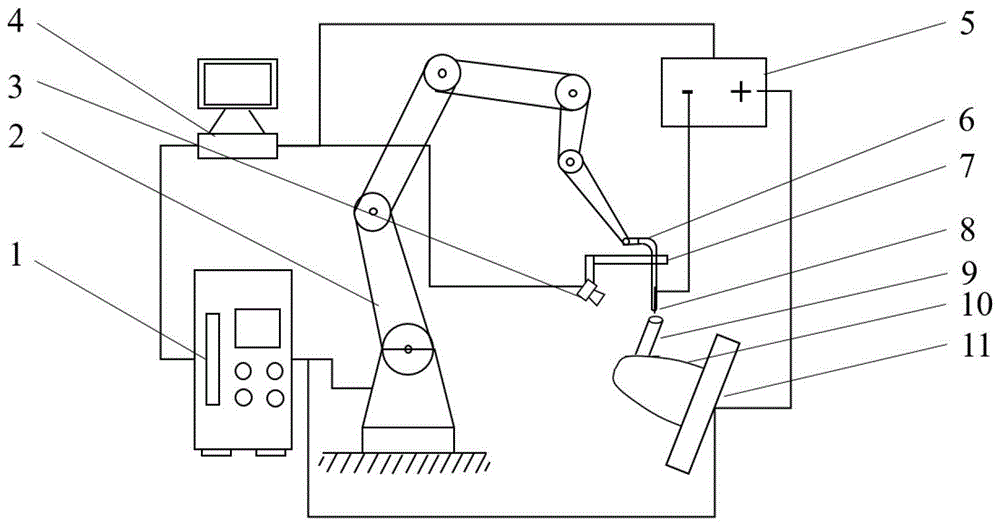
图1是本发明实施例曲母线锥形面点阵构件的增材制造装置结构示意图;Fig. 1 is a schematic structural diagram of an additive manufacturing device for a curved generatrix tapered surface lattice member according to an embodiment of the present invention;
图2是本发明实施例曲母线锥形面点阵构件的增材制造方法流程图;Fig. 2 is a flow chart of an additive manufacturing method for a curved generatrix tapered surface lattice member according to an embodiment of the present invention;
图3是本发明实施例曲母线锥形面点阵第一层点阵的结构示意图;Fig. 3 is a structural schematic diagram of the first layer of the lattice of the curved generatrix tapered surface lattice in the embodiment of the present invention;
图4是本发明实施例曲母线锥形面点阵第二层点阵的结构示意图;Fig. 4 is the structural schematic diagram of the second layer lattice of the curved generatrix tapered surface lattice of the embodiment of the present invention;
图5是本发明实施例单个胞元结构的结构示意图;Fig. 5 is a schematic structural diagram of a single cell structure in an embodiment of the present invention;
图6是本发明实施例单个胞元结构的成型路径点示意图;Fig. 6 is a schematic diagram of forming path points of a single cell structure according to an embodiment of the present invention;
图7中(a)~(d)是本发明实施例单个胞元结构的路径点精准调整示意图。(a)-(d) in FIG. 7 are schematic diagrams of precise adjustment of waypoints for a single cell structure according to an embodiment of the present invention.
在所有附图中,相同的附图标记用来表示相同的元件或结构,其中:1-机器人控制器,2-机器人,3-视觉系统,4-工控机,5-弧焊电源,6-弧焊枪,7-夹持件,8-丝材,9-杆件,10-曲母线锥形筒,11-变位机。In all drawings, the same reference numerals are used to represent the same elements or structures, wherein: 1-robot controller, 2-robot, 3-visual system, 4-industrial computer, 5-arc welding power supply, 6- Arc welding torch, 7-clamp, 8-wire, 9-rod, 10-curved generatrix cone, 11-positioner.
具体实施方式Detailed ways
为了使本发明的目的、技术方案及优点更加清楚明白,以下结合附图及实施例,对本发明进行进一步详细说明。应当理解,此处所描述的具体实施例仅仅用以解释本发明,并不用于限定本发明。此外,下面所描述的本发明各个实施方式中所涉及到的技术特征只要彼此之间未构成冲突就可以相互组合。In order to make the object, technical solution and advantages of the present invention clearer, the present invention will be further described in detail below in conjunction with the accompanying drawings and embodiments. It should be understood that the specific embodiments described here are only used to explain the present invention, not to limit the present invention. In addition, the technical features involved in the various embodiments of the present invention described below can be combined with each other as long as they do not constitute a conflict with each other.
本发明实施例提供的一种曲母线锥形面点阵构件的增材制造方法,包括如下步骤:An embodiment of the present invention provides an additive manufacturing method for a curved generatrix tapered surface lattice component, including the following steps:
S1、基于曲母线锥形面构建若干层点阵结构模型;S1. Construct several layers of lattice structure models based on the conical surface of the curved generatrix;
具体的,建立曲母线锥形面点阵构件的三维包络面,所述三维包络面表示每层点阵结构的厚度;基于所述三维包络面构建若干层点阵结构模型,其中,对任意一层点阵结构模型(第i层)由若干排和列的胞元结构
进一步的,基于所述三维包络面构建若干层点阵结构模型,包括:Further, several layers of lattice structure models are constructed based on the three-dimensional envelope surface, including:
(1)基于第i-1层的胞元结构的顶点坐标确定第i层的底点组合方式,所述底点组合方式中包括多个底点对,每个底点对对应第i层的一个胞元结构;(1) Based on the vertex coordinates of the cell structure of the i-1th layer, the base point combination mode of the i-th layer is determined. The base point combination mode includes a plurality of base point pairs, and each base point pair corresponds to the i-th layer. a cell structure;
在一些实施例中,基于第i-1层的胞元结构的顶点坐标确定第i层的底点组合方式,进一步包括:In some embodiments, determining the bottom point combination mode of the i-th layer based on the vertex coordinates of the cell structure of the i-1th layer further includes:
(11)获取所有第i-1层的胞元结构的顶点坐标;(11) Obtain the vertex coordinates of the cell structure of all the i-1th layers;
(12)以第i-1层的胞元结构的顶点坐标中的角落点为原点,基于最近邻算法开始匹配第一阈值内的若干其他顶点;(12) Taking the corner point in the vertex coordinates of the cell structure of the i-1th layer as the origin, start matching some other vertices in the first threshold based on the nearest neighbor algorithm;
(13)获取多种底点组合方式,并基于组合方式中的孤立点以及配对方式中的孤立点数方差值对组合方式进行评价,直至获得满足预设条件的底点组合方式。具体的,收敛条件为孤立点最少、胞元形状尽量统一。(13) Obtain a variety of bottom point combinations, and evaluate the combination methods based on the isolated points in the combination methods and the variance value of the number of isolated points in the pairing method, until a bottom point combination method that meets the preset conditions is obtained. Specifically, the convergence condition is that the number of outliers is the least, and the shape of the cells is as uniform as possible.
(2)根据底点对确定第i层的胞元结构。对任意一个底点对:(2) Determine the cell structure of the i-th layer according to the bottom point pair. For any pair of base points:
(21)获取所述底点对应的第i-1层对应的胞元结构,并基于此确定各胞元结构对应的法向量,其中,所述法向量为每个胞元结构的底点形状中心到顶点的连线向量;(21) Obtain the cell structure corresponding to the i-1th layer corresponding to the bottom point, and determine the normal vector corresponding to each cell structure based on this, wherein the normal vector is the bottom point shape of each cell structure The line vector from the center to the vertex;
(22)基于所述底点对中每一个底点对应的法向量确定第i层胞元结构对应的法向量;(22) Determine the normal vector corresponding to the i-th layer cell structure based on the normal vector corresponding to each bottom point in the bottom point pair;
在一些实施例中,基于所述底点对中每一个底点对应的法向量确定第i层胞元结构对应的法向量,进一步包括:基于所述每一个底点对应的法向量进行加权求和得到第i层胞元结构对应的法向量;In some embodiments, determining the normal vector corresponding to the i-th layer cell structure based on the normal vector corresponding to each bottom point in the bottom point pair further includes: performing weighted calculation based on the normal vector corresponding to each bottom point and get the normal vector corresponding to the i-th layer cell structure;
在一些实施例中,所述每一个底点对应的法向量对应的权重不同。In some embodiments, the weights corresponding to the normal vectors corresponding to each bottom point are different.
i层中的任意一个胞元的法向量由其基点对应的i-1层中的胞元结构的法向量进行确定。示例性地,如i层中H胞元由i-1层中的A、B、C三个胞元确定,则Zh=a*Za+b*Zb+c*Zc,a、b、c为超参数。在一些实施例中,a、b、c可以随动,以使得第i层的胞元的法向量可以随形状变化。例如,使b的权重增大,则胞元H的方向会朝向Zb的方向进行偏转。The normal vector of any cell in layer i is determined by the normal vector of the cell structure in layer i-1 corresponding to its base point. Exemplarily, if the cell H in the i layer is determined by the three cells A, B, and C in the i-1 layer, then Zh=a*Za+b*Zb+c*Zc, a, b, and c are hyperparameters. In some embodiments, a, b, and c can follow the shape, so that the normal vector of the cell in the i-th layer can change with the shape. For example, if the weight of b is increased, the direction of the cell H will be deflected toward the direction of Zb.
(23)获取第i层对应的三维包络面,基于所述第i层对应的三维包络面确定其与所述第i层的胞元结构的法向量的交点;(23) Obtain the three-dimensional envelope surface corresponding to the i-th layer, and determine the intersection point with the normal vector of the cell structure of the i-th layer based on the three-dimensional envelope surface corresponding to the i-th layer;
(24)基于所述交点确定第i层胞元结构的顶点坐标;(24) Determine the vertex coordinates of the i-th layer cell structure based on the intersection point;
在一些实施例中,所述基于所述交点确定第i层胞元结构的顶点坐标,包括:以所述交点作为第i层胞元结构的顶点。In some embodiments, the determining the vertex coordinates of the i-th layer cell structure based on the intersection point includes: using the intersection point as the vertex of the i-th layer cell structure.
在一些实施例中,所述基于所述交点确定第i层胞元结构的顶点坐标,包括:基于电弧增材工艺确定单点沉积量;基于所述单点沉积量对所述交点位置进行修正,获得所述顶点坐标。In some embodiments, the determining the vertex coordinates of the i-th layer cell structure based on the intersection point includes: determining the single-point deposition amount based on the arc additive process; and correcting the intersection point position based on the single-point deposition amount , to obtain the vertex coordinates.
(25)基于所述顶点坐标以及底点对确定第i层的胞元结构。(25) Determine the cell structure of the i-th layer based on the vertex coordinates and the bottom point pairs.
在一些实施例中,所述第i层的胞元结构与所述第i-1层的胞元结构不同。In some embodiments, the cell structure of the i-th layer is different from the cell structure of the i-1-th layer.
S2、制定每一层点阵结构的打印策略,基于运动控制机构以及电弧焊机实现所述每一层点阵结构的电弧增材制造。S2. Formulate a printing strategy for each layer of lattice structure, and implement arc additive manufacturing of each layer of lattice structure based on a motion control mechanism and an arc welding machine.
在一些实施例中,对曲母线锥形面点阵构件的电弧增材制造通过增材制造装置实现,如图1所示,所述增材制造装置包括电弧增材制造系统、视觉系统3和控制系统,其中:In some embodiments, the arc additive manufacturing of the curved generatrix tapered surface lattice member is realized by an additive manufacturing device, as shown in Figure 1, the additive manufacturing device includes an arc additive manufacturing system, a
所述电弧增材制造系统包括机器人2、弧焊枪6和变位机11,所述机器人2用于带动所述弧焊枪6运动;所述弧焊枪6与弧焊电源5连接,弧焊枪6用于在曲母线锥形筒10上打印点阵结构;所述变位机11用于调整曲母线锥形筒10位置;The arc additive manufacturing system includes a
所述视觉系统3通过夹持件7固定在所述弧焊枪6上,该视觉系统3(可为相机)用来拍摄弧焊枪6上丝材8和曲母线锥形筒上杆件9的位置;The
所述控制系统包括工控机4和机器人控制器1,所述工控机4用于接收视觉系统3拍摄的丝材与杆件的位置,进而计算丝材末端中心点与杆件顶点相对位置的偏差值,当相对位置偏差值大于预设值时,工控机4发送指令给机器人控制器1,进而机器人控制器1控制机器人轴协同运动使丝材移动一定值到达目标位置。The control system includes an
在一些实施例中,如图2所示,步骤S2具体包括:In some embodiments, as shown in FIG. 2, step S2 specifically includes:
S21、打印策略制定;所述的曲母线锥形面点阵打印策略分为:第i-1层点阵的打印,第i层点阵的打印。S21. Formulation of a printing strategy; the dot matrix printing strategy of the curved generatrix tapered surface is divided into: printing of the dot matrix of the i-1th layer, and printing of the dot matrix of the i-th layer.
S22、第i-1层某一排圆周点阵的打印;首先,将变位机翻转到某一角度,进行第一层某一排第一列点阵单胞的打印,完成后,调整变位机旋转角度进行该排第二列点阵单胞的打印,按照重复“打印单胞-旋转变位机-打印单胞-旋转变位机”的方法,完成该排圆周点阵的打印。S22. Printing of a certain row of circular dot matrix on the i-1th layer; first, flip the positioner to a certain angle to print the first row of dot matrix unit cells in the first layer. According to the rotation angle of the positioner, the unit cell of the second column of dot matrix in the row is printed, and the printing of the row of circumferential dot matrix is completed according to the method of repeating "printing unit - rotating displacement machine - printing unit - rotating displacement machine".
S23、第i-1层点阵的打印;完成上述排圆周点阵的打印后,翻转变位机到一定角度,按照上述S22步骤完成下一排圆周点阵的打印,按照重复:“打印圆周点阵-翻转变位机-打印圆周点阵-翻转变位机”的方法,完成第i-1层点阵的打印。S23. Printing of the i-1th layer of dot matrix; after completing the printing of the above row of circumferential dot matrix, flip the positioner to a certain angle, complete the printing of the next row of circumferential dot matrix according to the above S22 steps, and repeat: "Print circle dot matrix-reversal transposition machine-printing circular dot matrix-reversal transposition machine" method to complete the printing of the i-1th layer of dot matrix.
S23、第i层某一排圆周点阵的打印;首先,将变位机翻转到某一角度,进行第i层某一排第一列点阵单胞的打印,完成后,调整变位机旋转角度进行第i层该排第二列的打印,按照重复“打印单胞-旋转变位机-打印单胞-旋转变位机”的方法,完成第i层该排所有列点阵单胞的打印。S23. Printing of a certain row of circular dot matrix on the i-th layer; first, flip the positioner to a certain angle to print the unit cell of the first column of dot matrix in a certain row of the i-th layer. After completion, adjust the positioner Rotate the angle to print the second column of the row in the i-th layer, and complete all the dot matrix cells in the row of the i-th layer by repeating the method of "printing unit cell-rotation displacement machine-printing unit cell-rotation displacement machine" of print.
S24、第i层点阵的打印;完成上述排圆周点阵的打印后,翻转变位机到一定角度,按照上述S24步骤完成第i层下一排圆周点阵的打印,按照重复“打印圆周点阵-翻转变位机-打印圆周点阵-翻转变位机”的方法,完成第i层点阵的打印。S24, the printing of the i-th layer of dot matrix; after completing the printing of the above-mentioned row of circumferential dot-matrix, turn the positioner to a certain angle, complete the printing of the next row of dot-matrix of the i-th layer according to the above-mentioned steps of S24, and repeat "printing the circle dot matrix-reversal transposition machine-printing circular dot matrix-reversal transposition machine" method to complete the printing of the i-th layer of dot matrix.
在一些实施例中,每个胞元结构中包含四根杆件,采用铝合金作为点阵结构材料,铝合金具有质量轻、比强度高和易加工成形等优点,使得曲母线锥形面铝合金点阵结构件能同时发挥金字塔点阵结构属性和铝合金材质属性的优势。In some embodiments, each cell structure contains four rods, and aluminum alloy is used as the material of the lattice structure. Alloy lattice structural parts can take advantage of both the pyramidal lattice structural properties and the aluminum alloy material properties.
在一些实施例中,曲母线锥形点阵单胞的堆积工艺参数,同一个点阵单胞下的四根杆件的成型堆积参数是不同的。In some embodiments, the stacking process parameters of the curved generatrix tapered lattice unit cell and the forming stacking parameters of the four rods under the same lattice unit cell are different.
为使本发明更清楚,以一具体的曲母线锥形面点阵构件为例对增材制造过程进行说明。包括如下步骤:In order to make the present invention more clear, a specific curved generatrix tapered surface lattice component is taken as an example to illustrate the additive manufacturing process. Including the following steps:
a)曲母线锥形面点阵结构三维建模和分区打印策略制定。a) The 3D modeling of the lattice structure of the conical surface of the curved generatrix and the formulation of the partition printing strategy.
在此步骤中,针对作为制造对象的曲母线锥形面点阵结构件,对其进行三维建模,然后对所获得的三维模型进行区域划分:将曲母线锥形面点阵结构分为2层点阵,第一层点阵由几排圆周点阵组成,所述的圆周点阵由几列,四根杆件长度和倾斜角度不同的单胞组成。所述的第二层点阵由几排圆周点阵组成,所述的圆周点阵由几排,四根杆件长度和倾斜角度不同的杆件形成的单胞组成。In this step, 3D modeling is performed on the lattice structure of the conical surface of the curved generatrix as the manufacturing object, and then the obtained 3D model is divided into regions: the lattice structure of the conical surface of the curved generatrix is divided into 2 A layer of lattices, the first layer of lattices is composed of several rows of circular lattices, and the circular lattices are composed of several columns and four unit cells with different lengths and inclination angles of rods. The second layer of lattice is composed of several rows of circular lattices, and the circular lattice is composed of several rows of unit cells formed by four rods with different lengths and inclination angles.
上述曲母线锥形面点阵结构三维模型的制定如图3和图4所示。其中,曲母线锥形面点阵结构件总体尺寸高度为300mm,第一层点阵如图3,包含11排圆周点阵;第二层点阵包含12排圆周点阵,第二层点阵如图4。所述的第一层点阵由11排圆周点阵构成,第1-5排圆周点阵分别由28列点阵单胞组成,第6-8排圆周点阵分别由8列点阵单胞组成,第9-10排圆周点阵分别由33列点阵单胞组成,第11排圆周点阵由36列点阵单胞组成。所述的第二层点阵包含12排圆周点阵,第12-17排周点阵分别由28列点阵单胞组成,第18-19排圆周点阵分别由8列点阵单胞组成,第20-22排圆周点阵分别由33列点阵单胞组成,第23排圆周点阵由36列点阵单胞组成。图5为上述第一层1排圆周点阵单胞的示意图,其中L1=L3=15mm>L2=L4=13.5mm,θ1=θ3=45°<θ2=θ4=47.5°,点阵杆件直径为3mm。The formulation of the 3D model of the lattice structure of the conical surface of the curved generatrix is shown in Figure 3 and Figure 4. Among them, the overall size and height of the curved generatrix tapered surface lattice structure is 300mm. The first layer of lattice is shown in Figure 3, including 11 rows of circular lattices; the second layer of lattices contains 12 rows of Figure 4. The first layer of lattices is composed of 11 rows of circular lattices, the 1st-5th rows of circular lattices are composed of 28 rows of lattice cells, and the 6th-8th rows of circular lattices are respectively composed of 8 rows of lattice cells The 9th to 10th rows of circular lattices are composed of 33 rows of lattice cells, and the 11th row of circular lattices is composed of 36 rows of lattice cells. The second layer of lattices includes 12 rows of circular lattices, the 12th-17th rows of circumferential lattices are composed of 28 rows of lattice cells, and the 18th-19th rows of circular lattices are respectively composed of 8 rows of lattice cells , the 20th-22nd rows of circular lattices are composed of 33 rows of lattice cells, and the 23rd row of circular lattices is composed of 36 rows of lattice cells. Fig. 5 is a schematic diagram of a row of circumferential lattice unit cells in the first layer above, where L 1 =L 3 =15mm>L 2 =L 4 =13.5mm, θ 1 =θ 3 =45°<θ 2 =θ 4 = 47.5°, the diameter of the lattice rod is 3mm.
b)单胞曲面切片和堆积成形。b) Slicing and stacking of unit cell surfaces.
在此步骤中,建立一个曲母线锥形面点阵单胞的模型,利用切片软件切片获得曲母线锥形面点阵单胞打印路径点,并通过自主开发的JAVA语言代码转化为机器人指令src文件,导入机器人控制平台中。如图6所示,机器人控制系统控制变位机带动曲母线锥形筒到达目标位置,机器人控制系统控制机器人轴运动带动弧焊枪到达一个单胞第一层1号打印路径点,完成单胞第一层1号打印路径点的打印后,机器人控制系统控制机器人轴运动带动弧焊枪到达一个单胞第一层2号打印路径点,完成单胞第一层2号打印路径点的打印后,机器人控制系统控制机器人轴运动带动弧焊枪到达一个单胞第一层3号打印路径点,完成单胞第一层3号打印路径点的打印后,机器人控制系统控制机器人轴运动带动弧焊枪到达一个单胞第一层4号打印路径点,完成单胞第一层4号打印路径点的打印后,直至完成第一层的打印。机器人控制系统控制机器人轴运动带动弧焊枪到达下一层1号打印路径点,按照上述逐层打印方法,直至完成第二层的打印。以此类推,直至完成一个单胞所有堆积层的电弧增材制造。In this step, a model of the lattice unit cell of the conical surface of the curved generatrix is established, and the printing path points of the lattice unit cell of the conical surface of the curved generatrix are obtained by slicing with slicing software, and converted into robot instructions src through the self-developed JAVA language code file and import it into the robot control platform. As shown in Figure 6, the robot control system controls the positioner to drive the conical cylinder of the curved busbar to reach the target position, and the robot control system controls the movement of the robot axis to drive the arc welding torch to reach the No. After the printing of the No. 1 printing path point of the first layer, the robot control system controls the movement of the robot shaft to drive the arc welding torch to reach the No. 2 printing path point of the first layer of a unit cell. After printing the No. 2 printing path point of the first layer of the unit cell, the robot The control system controls the movement of the axis of the robot to drive the arc welding torch to reach the No. 3 printing path point on the first layer of the unit cell. No. 4 printing path point of the first layer of the unit cell, after the printing of the No. 4 printing path point of the first layer of the unit cell is completed, until the printing of the first layer is completed. The robot control system controls the movement of the robot axis to drive the arc welding torch to the No. 1 printing path point of the next layer, and follow the above layer-by-layer printing method until the second layer of printing is completed. And so on, until the arc additive manufacturing of all stacked layers of a unit cell is completed.
作为本发明的一个优势所在,在整个点阵构件单胞电弧增材制造过程中,每当弧焊枪到达一个切片起弧路径点时,视觉系统实时测量当前弧焊枪丝材末端中心点与杆件顶端中心点的相对位置,计算出横向偏移量Xp。接着,依据上述偏移量对弧焊枪位置执行实时修正,进行电弧打印。以此方式,能够确保弧焊枪处于精准起弧位置,保证成型点阵杆件的角度、圆度和直径精度,最终能够得到高精度曲母线锥形面点阵构件。As an advantage of the present invention, during the entire unit cell arc additive manufacturing process of lattice components, whenever the arc welding torch reaches a slice arc starting path point, the vision system measures the center point of the wire end of the current arc welding torch and the rod in real time. The relative position of the top center point is used to calculate the lateral offset Xp. Then, real-time correction is performed on the position of the arc torch according to the above-mentioned offset to perform arc printing. In this way, it is possible to ensure that the arc welding torch is at a precise arc starting position, to ensure the accuracy of the angle, roundness and diameter of the formed lattice rod, and finally to obtain a high-precision curved generatrix tapered surface lattice component.
更具体而言,在整个电弧增材制造过程中,在一个单胞第一层打印结束后,从第二层开始打印时,开始实时修正。以电弧增材制造图5所示的单胞一个具体实施方式为例,做如下示范性解释说明:More specifically, during the entire electric arc additive manufacturing process, real-time corrections are initiated when printing starts from the second layer of a unit cell after the first layer has been printed. Taking a specific implementation of the unit cell shown in Figure 5 in the arc additive manufacturing as an example, the following exemplary explanation is given:
一个单胞第二层1号点的打印:Printing of
在弧焊枪到达点阵单胞杆件起弧位置时,使用照相机对杆件与丝材的位置进行拍照。工控机收到照片后,依次进行全局阈值分割、轮廓提取、特定区域提取,计算得到焊丝末端中心点与杆件顶部中心点的位置偏差值Xp1,如图7中(a)所示。When the arc welding torch reaches the arc starting position of the lattice unit cell rod, a camera is used to take pictures of the position of the rod and the wire. After receiving the photos, the industrial computer performs global threshold segmentation, contour extraction, and specific area extraction in sequence, and calculates the positional deviation Xp 1 between the center point of the end of the welding wire and the center point of the top of the rod, as shown in Figure 7(a).
阈值判定:将上述位置偏差值Xp1与阈值进行判断,优选偏差阈值为0.05mm。当Xp1>0.05时,表明该处丝材位置发生偏差,工控机向机器人控制系统发动偏移Xp1指令,机器人轴协同运动Xp1值到达精准起弧点;当Xp1<0.05时,表明此时焊丝位置正确,工控机不向机器人控制系统发动偏移Xp1指令。Threshold judgment: Judgment is made between the positional deviation value Xp 1 and the threshold value, preferably the deviation threshold value is 0.05 mm. When Xp 1 >0.05, it indicates that there is a deviation in the position of the wire, and the industrial computer sends an offset Xp 1 command to the robot control system, and the Xp 1 value of the robot axis coordinated motion reaches the precise arc starting point; when Xp 1 <0.05, it indicates At this time, the position of the welding wire is correct, and the industrial computer does not initiate an offset Xp 1 command to the robot control system.
电弧增材制造:在上述弧焊枪带动焊丝到精准起弧点后,工控机向焊机发送弧焊指令。Arc additive manufacturing: After the above-mentioned arc welding torch drives the welding wire to the precise arc starting point, the industrial computer sends an arc welding command to the welding machine.
上述电弧增材制造堆积电流70A,堆积电压8.5V。The stacking current of the above-mentioned arc additive manufacturing is 70A, and the stacking voltage is 8.5V.
一个单胞第二层2号点的打印:Printing of
在弧焊枪到达点阵单胞杆件起弧位置时,使用照相机对杆件与丝材的位置进行拍照。工控机收到照片后,依次进行全局阈值分割、轮廓提取、特定区域提取,计算得到焊丝末端中心点与杆件顶部中心点的位置偏差值Xp2,如图7中(b)所示。When the arc welding torch reaches the arc starting position of the lattice unit cell rod, a camera is used to take pictures of the position of the rod and the wire. After the industrial computer receives the photos, it performs global threshold segmentation, contour extraction, and specific area extraction in sequence, and calculates the position deviation value Xp 2 between the center point of the end of the welding wire and the center point of the top of the rod, as shown in (b) in Figure 7.
阈值判定:将上述位置偏差值Xp2与阈值进行判断,优选偏差阈值为0.05mm。当Xp2>0.05时,表明该处丝材位置发生偏差,工控机向机器人控制系统发动偏移Xp2指令,机器人轴协同运动Xp2值到达精准起弧点;当Xp2<0.05时,表明此时焊丝位置正确,工控机不向机器人控制系统发动偏移Xp2指令。Threshold judgment: Judgment is made between the above-mentioned position deviation value Xp 2 and a threshold value, preferably the deviation threshold value is 0.05mm. When Xp 2 >0.05, it indicates that there is a deviation in the position of the wire, and the industrial computer sends an offset Xp 2 command to the robot control system, and the Xp 2 value of the robot axis coordinated motion reaches the precise arc starting point; when Xp 2 <0.05, it indicates At this time, the position of the welding wire is correct, and the industrial computer does not send an offset Xp 2 command to the robot control system.
电弧增材制造:在上述弧焊枪带动焊丝到精准起弧点后,工控机向焊机发送弧焊指令。Arc additive manufacturing: After the above-mentioned arc welding torch drives the welding wire to the precise arc starting point, the industrial computer sends an arc welding command to the welding machine.
上述电弧增材制造堆积电流80A,堆积电压8.8V。The stacking current of the above-mentioned arc additive manufacturing is 80A, and the stacking voltage is 8.8V.
一个单胞第二层3号点的打印:Printing of
在弧焊枪到达点阵单胞杆件起弧位置时,使用照相机对杆件与丝材的位置进行拍照。工控机收到照片后,依次进行全局阈值分割、轮廓提取、特定区域提取,计算得到焊丝末端中心点与杆件顶部中心点的位置偏差值Xp3,如图7中(c)所示。When the arc welding torch reaches the arc starting position of the lattice unit cell rod, a camera is used to take pictures of the position of the rod and the wire. After the industrial computer receives the photos, it performs global threshold segmentation, contour extraction, and specific area extraction in sequence, and calculates the positional deviation Xp 3 between the center point of the end of the welding wire and the center point of the top of the rod, as shown in (c) in Figure 7.
阈值判定:将上述位置偏差值Xp3与阈值进行判断,优选偏差阈值为0.05mm。当Xp3>0.05时,表明该处丝材位置发生偏差,工控机向机器人控制系统发动偏移Xp3指令,机器人轴协同运动Xp3值到达精准起弧点;当Xp3<0.05时,表明此时焊丝位置正确,工控机不向机器人控制系统发动偏移Xp3指令。Threshold judgment: Judgment is made between the above-mentioned position deviation value Xp 3 and a threshold value, preferably the deviation threshold value is 0.05mm. When Xp 3 >0.05, it indicates that there is a deviation in the position of the wire, and the industrial computer sends an offset Xp 3 command to the robot control system, and the Xp 3 value of the robot axis coordinated motion reaches the precise arc starting point; when Xp 3 <0.05, it indicates At this time, the position of the welding wire is correct, and the industrial computer does not send an offset Xp 3 command to the robot control system.
电弧增材制造:在上述弧焊枪带动焊丝到精准起弧点后,工控机向焊机发送弧焊指令。Arc additive manufacturing: After the above-mentioned arc welding torch drives the welding wire to the precise arc starting point, the industrial computer sends an arc welding command to the welding machine.
上述电弧增材制造堆积电流70A,堆积电压8.5V。The stacking current of the above-mentioned arc additive manufacturing is 70A, and the stacking voltage is 8.5V.
一个单胞第二层4号点的打印:Printing of
在弧焊枪到达点阵单胞杆件起弧位置时,使用照相机对杆件与丝材的位置进行拍照。工控机收到照片后,依次进行全局阈值分割、轮廓提取、特定区域提取,计算得到焊丝末端中心点与杆件顶部中心点的位置偏差值Xp4,如图7中(d)所示。When the arc welding torch reaches the arc starting position of the lattice unit cell rod, a camera is used to take pictures of the position of the rod and the wire. After the industrial computer receives the photos, it performs global threshold segmentation, contour extraction, and specific area extraction in sequence, and calculates the position deviation value Xp 4 between the center point of the end of the welding wire and the center point of the top of the rod, as shown in (d) in Figure 7.
阈值判定:将上述位置偏差值Xp4与阈值进行判断,优选偏差阈值为0.05。当Xp4>0.05时,表明该处丝材位置发生偏差,工控机向机器人控制系统发动偏移Xp4指令,机器人轴协同运动Xp4值到达精准起弧点;当Xp4<0.05时,表明此时焊丝位置正确,工控机不向机器人控制系统发动偏移Xp4指令。Threshold value determination: determine the above-mentioned position deviation value Xp 4 with a threshold value, preferably the deviation threshold value is 0.05. When Xp 4 >0.05, it indicates that there is a deviation in the position of the wire, and the industrial computer sends an offset Xp 4 command to the robot control system, and the Xp 4 value of the robot axis coordinated motion reaches the precise arc starting point; when Xp 4 <0.05, it indicates At this time, the position of the welding wire is correct, and the industrial computer does not initiate an offset Xp 4 command to the robot control system.
电弧增材制造:在上述弧焊枪带动焊丝到精准起弧点后,工控机向焊机发送弧焊指令。Arc additive manufacturing: After the above-mentioned arc welding torch drives the welding wire to the precise arc starting point, the industrial computer sends an arc welding command to the welding machine.
上述电弧增材制造堆积电流80A,堆积电压8.8V。The stacking current of the above-mentioned arc additive manufacturing is 80A, and the stacking voltage is 8.8V.
c)同一排圆周点阵的打印。c) Printing of the same row of circular dot matrix.
完成一个圆周点阵第一个点阵单胞的打印后,旋转变位机角度θ5,到达第2个点阵单胞打印位置,重复步骤b),完成第2个点阵单胞打印;再次旋转角度θ5,到达第3个点阵单胞打印位置,重复步骤b),完成第3个点阵单胞的打印;依次类堆,直至完成该排圆周点阵的打印。After completing the printing of the first dot matrix unit cell of a circular dot matrix, rotate the positioner at an angle θ 5 to reach the printing position of the second dot matrix unit cell, and repeat step b) to complete the printing of the second dot matrix unit cell; Rotate the angle θ 5 again to reach the printing position of the third dot matrix unit cell, repeat step b) to complete the printing of the third dot matrix unit cell; pile up in order until the printing of the row of circular dot matrix is completed.
以一个实际的圆周点阵打印为例进行对该步骤进行详细说明,按照上述方法打印第一层点阵中的第1排圆周点阵,第1排圆周点阵由28列点阵单胞组成,变位机翻转角度为65.18°。按照步骤b)完成第1列点阵单胞的打印后,旋转变位机角度为12.86°,完成第2列点阵单胞打印;再次旋转角度12.86°,到达第3列点阵单胞打印位置,重复步骤b),完成第3列点阵单胞的打印;依次类堆,直至完成该排28个圆周点阵的打印。Take an actual circular dot matrix printing as an example to describe this step in detail. Print the first row of circular dot matrix in the first layer of dot matrix according to the above method. The first row of circular dot matrix is composed of 28 rows of dot matrix cells , the flip angle of the positioner is 65.18°. After completing the printing of the first column of dot matrix cells according to step b), rotate the positioner at an angle of 12.86° to complete the printing of the second column of dot matrix cells; rotate again at an angle of 12.86° to reach the printing of the third column of dot matrix cells position, repeat step b) to complete the printing of the dot matrix unit cell in the third column; pile up in sequence until the printing of the row of 28 circular dot matrix is completed.
d)第一层11排圆周点阵的打印。d) Printing of 11 rows of circular dot matrix on the first layer.
完成第一层第1排圆周点阵打印后,变位机翻转角度θ6到第一层第2排圆周点阵位置,重复步骤b)、步骤c),直至完成第2排圆周点阵打印。完成第2排圆周点阵打印后,变位机翻转角度θ7到第一层第3排圆周点阵位置,重复步骤b)、步骤c),完成第3排圆周点阵打印。依次类堆,直至完成第一层点阵11排圆周点阵的打印。After finishing the printing of the 1st row of circular dot matrix on the first layer, the positioner flips the angle θ 6 to the position of the 2nd row of circular dot matrix on the first layer, and repeats step b) and step c) until the printing of the 2nd row of circular dot matrix is completed . After the second row of circular dot matrix printing is completed, the positioner is flipped at an angle of θ 7 to the position of the third row of circular dot matrix on the first layer, and step b) and step c) are repeated to complete the printing of the third row of circular dot matrix. Stack in sequence until the printing of the first layer of
以一个实际的第一层点阵打印为例,对该步骤进行详细说明,按照上述方法打印第一层点阵。变位机翻转角度为65.18°,按照步骤b)、步骤c)完成第1排圆周点阵的打印后;翻转变位机角度为66.99°,按照步骤b)、步骤c)完成第2排圆周点阵的打印;翻转变位机角度为67.77°,按照步骤b)、步骤c)完成第3排圆周点阵的打印;翻转变位机角度为70.22°,依次类堆,直至完成第一层11排圆周点阵的打印。上述第一层11排圆周点阵按照所占排号1-11号分别所对应的翻转角度分别为:65.18°,66.99°,67.77°,70.22°,71.86°,73.58°,75.31°,77.04°,78.77°,79.95°,90°。Taking an actual first layer of dot matrix printing as an example, this step is described in detail, and the first layer of dot matrix is printed according to the above method. The flip angle of the positioner is 65.18°, follow steps b) and c) to complete the printing of the first row of circular dot matrix; flip the positioner to an angle of 66.99°, follow steps b) and step c) to complete the second row of circles Dot matrix printing; the angle of the flipping positioner is 67.77°, and the printing of the third row of circular dot matrixes is completed according to step b) and step c); the angle of the flipping positioner is 70.22°, and stacked in sequence until the first layer is completed Printing of 11 rows of circular dot matrix. The above-mentioned 11 rows of circular lattices on the first layer correspond to the flip angles corresponding to the row numbers 1-11 respectively: 65.18°, 66.99°, 67.77°, 70.22°, 71.86°, 73.58°, 75.31°, 77.04° , 78.77°, 79.95°, 90°.
e)曲母线锥形面第二层点阵的打印。e) Printing of the second layer of dot matrix on the tapered surface of the curved generatrix.
完成曲母线锥形面第一层点阵的打印后,按照上述步骤b)、c)、d)直至完成曲母线锥形面第二层点阵的打印。After the first layer of dot matrix printing on the conical surface of the curved generatrix is completed, follow the above steps b), c), and d) until the printing of the second layer of dot matrix on the conical surface of the curved generatrix is completed.
本领域的技术人员容易理解,以上所述仅为本发明的较佳实施例而已,并不用以限制本发明,凡在本发明的精神和原则之内所作的任何修改、等同替换和改进等,均应包含在本发明的保护范围之内。It is easy for those skilled in the art to understand that the above descriptions are only preferred embodiments of the present invention, and are not intended to limit the present invention. Any modifications, equivalent replacements and improvements made within the spirit and principles of the present invention, All should be included within the protection scope of the present invention.
Claims (10)
Priority Applications (1)
| Application Number | Priority Date | Filing Date | Title |
|---|---|---|---|
| CN202210784696.6A CN115121809B (en) | 2022-06-29 | 2022-06-29 | Curved generatrix conical surface lattice structure and additive manufacturing method and device thereof |
Applications Claiming Priority (1)
| Application Number | Priority Date | Filing Date | Title |
|---|---|---|---|
| CN202210784696.6A CN115121809B (en) | 2022-06-29 | 2022-06-29 | Curved generatrix conical surface lattice structure and additive manufacturing method and device thereof |
Publications (2)
| Publication Number | Publication Date |
|---|---|
| CN115121809A CN115121809A (en) | 2022-09-30 |
| CN115121809B true CN115121809B (en) | 2023-04-07 |
Family
ID=83381868
Family Applications (1)
| Application Number | Title | Priority Date | Filing Date |
|---|---|---|---|
| CN202210784696.6A Active CN115121809B (en) | 2022-06-29 | 2022-06-29 | Curved generatrix conical surface lattice structure and additive manufacturing method and device thereof |
Country Status (1)
| Country | Link |
|---|---|
| CN (1) | CN115121809B (en) |
Families Citing this family (1)
| Publication number | Priority date | Publication date | Assignee | Title |
|---|---|---|---|---|
| CN119940153B (en) * | 2025-04-07 | 2025-07-29 | 南通理工学院 | Gradient lattice structure generation and optimization method and device for laser additive manufacturing |
Citations (2)
| Publication number | Priority date | Publication date | Assignee | Title |
|---|---|---|---|---|
| CN112846230A (en) * | 2021-01-07 | 2021-05-28 | 北京工业大学 | Method for preparing lattice structure amorphous-nanocrystalline alloy by using laser additive |
| CN114239356A (en) * | 2021-12-15 | 2022-03-25 | 上海交通大学 | Conformal lattice material design method based on finite element grid |
Family Cites Families (3)
| Publication number | Priority date | Publication date | Assignee | Title |
|---|---|---|---|---|
| US9180010B2 (en) * | 2012-04-06 | 2015-11-10 | Howmedica Osteonics Corp. | Surface modified unit cell lattice structures for optimized secure freeform fabrication |
| US10634143B2 (en) * | 2015-12-23 | 2020-04-28 | Emerson Climate Technologies, Inc. | Thermal and sound optimized lattice-cored additive manufactured compressor components |
| US11817588B2 (en) * | 2018-10-04 | 2023-11-14 | Carnegie Mellon University | Three-dimensional lattice batteries via additive manufacturing |
-
2022
- 2022-06-29 CN CN202210784696.6A patent/CN115121809B/en active Active
Patent Citations (2)
| Publication number | Priority date | Publication date | Assignee | Title |
|---|---|---|---|---|
| CN112846230A (en) * | 2021-01-07 | 2021-05-28 | 北京工业大学 | Method for preparing lattice structure amorphous-nanocrystalline alloy by using laser additive |
| CN114239356A (en) * | 2021-12-15 | 2022-03-25 | 上海交通大学 | Conformal lattice material design method based on finite element grid |
Also Published As
| Publication number | Publication date |
|---|---|
| CN115121809A (en) | 2022-09-30 |
Similar Documents
| Publication | Publication Date | Title |
|---|---|---|
| Li et al. | Wire and arc additive manufacturing of aluminum alloy lattice structure | |
| CN111496257A (en) | A metal minimally curved gradient porous heat dissipation element and its additive manufacturing method | |
| CN105834427B (en) | The device and method of brilliant part is oriented using the 3D printing of multiple laser aids in temperature control | |
| CN101362511B (en) | Cooperative control method for aircraft component pose adjustment based on four locators | |
| CN115121809B (en) | Curved generatrix conical surface lattice structure and additive manufacturing method and device thereof | |
| CN109894614A (en) | The method and its application of trajectory planning are filled on a kind of developable surface | |
| US20160167132A1 (en) | Additive manufacturing of porous scaffold structures | |
| CN105773961B (en) | 3D printing method | |
| CN108555464A (en) | A kind of large complicated carved dynamic focusing laser processing and system | |
| CN111037054B (en) | Arc fuse curve surface additive pose modeling method and control method | |
| CN101185970A (en) | Composite rapid prototyping method based on laser deposition modeling and subtractive forming | |
| CN114799521A (en) | Skin skeleton laser automatic welding method and device and electronic equipment | |
| CN110000381A (en) | A kind of electric arc increase and decrease material composite integrated manufacturing method of Propeller Model | |
| Zheng et al. | Directed energy deposition-arc of aluminum-alloy curved-generatrix-shell pyramid lattice structure | |
| CN113042754B (en) | Trajectory planning method for lightweight lattice sandwich panel formed by metal droplet 3D printing | |
| CN110125406A (en) | A kind of low-expansion coefficient three-dimensional space lattice structure and its manufacturing process | |
| CN115846687A (en) | Bouliland spiral stacking structure and preparation method thereof | |
| CN109145404B (en) | Porous structure modeling method with controllable pore characteristics and modulus matching and preparation method | |
| Gradl et al. | Introduction to additive manufacturing for propulsion and energy systems | |
| CN109484676B (en) | An Equivalent Attitude Control Processing Method for Online Trajectory Planning of Vertical Take-off and Landing Rockets | |
| CN115329632A (en) | Method for establishing annular path laser deep melting welding heat source of thick-wall circular pipe workpiece | |
| CN107234239B (en) | The arc deposited laser of robot pose control forges increasing material manufacturing method and equipment | |
| CN114425626B (en) | Directional energy deposition manufacturing method based on curved surface cantilever structure and product | |
| CN116921701B (en) | Multilayer single-pass printing path planning method for special-shaped metal structural member | |
| CN110548871A (en) | Interfacial Microstructure of Heterogeneous Multi-material Components Prepared by Selective Laser Melting Technology |
Legal Events
| Date | Code | Title | Description |
|---|---|---|---|
| PB01 | Publication | ||
| PB01 | Publication | ||
| SE01 | Entry into force of request for substantive examination | ||
| SE01 | Entry into force of request for substantive examination | ||
| GR01 | Patent grant | ||
| GR01 | Patent grant |