CN115108490A - Light heavy-load parallel lifting mechanism - Google Patents
Light heavy-load parallel lifting mechanism Download PDFInfo
- Publication number
- CN115108490A CN115108490A CN202110294098.6A CN202110294098A CN115108490A CN 115108490 A CN115108490 A CN 115108490A CN 202110294098 A CN202110294098 A CN 202110294098A CN 115108490 A CN115108490 A CN 115108490A
- Authority
- CN
- China
- Prior art keywords
- lifting
- branched chain
- branch
- connecting rod
- chain connecting
- Prior art date
- Legal status (The legal status is an assumption and is not a legal conclusion. Google has not performed a legal analysis and makes no representation as to the accuracy of the status listed.)
- Pending
Links
- 230000007246 mechanism Effects 0.000 title claims abstract description 46
- 230000000452 restraining effect Effects 0.000 abstract description 27
- 238000010586 diagram Methods 0.000 description 8
- 230000005484 gravity Effects 0.000 description 6
- 230000008439 repair process Effects 0.000 description 2
- 230000004044 response Effects 0.000 description 2
- 229910000838 Al alloy Inorganic materials 0.000 description 1
- 230000015572 biosynthetic process Effects 0.000 description 1
- 210000000078 claw Anatomy 0.000 description 1
- 230000006872 improvement Effects 0.000 description 1
- 230000010354 integration Effects 0.000 description 1
- 238000012423 maintenance Methods 0.000 description 1
- 238000000034 method Methods 0.000 description 1
- 230000004048 modification Effects 0.000 description 1
- 238000012986 modification Methods 0.000 description 1
- 230000008092 positive effect Effects 0.000 description 1
- 238000003786 synthesis reaction Methods 0.000 description 1
Images


Classifications
-
- B—PERFORMING OPERATIONS; TRANSPORTING
- B66—HOISTING; LIFTING; HAULING
- B66F—HOISTING, LIFTING, HAULING OR PUSHING, NOT OTHERWISE PROVIDED FOR, e.g. DEVICES WHICH APPLY A LIFTING OR PUSHING FORCE DIRECTLY TO THE SURFACE OF A LOAD
- B66F7/00—Lifting frames, e.g. for lifting vehicles; Platform lifts
- B66F7/06—Lifting frames, e.g. for lifting vehicles; Platform lifts with platforms supported by levers for vertical movement
- B66F7/065—Scissor linkages, i.e. X-configuration
- B66F7/0658—Multiple scissor linkages horizontally arranged
-
- B—PERFORMING OPERATIONS; TRANSPORTING
- B66—HOISTING; LIFTING; HAULING
- B66F—HOISTING, LIFTING, HAULING OR PUSHING, NOT OTHERWISE PROVIDED FOR, e.g. DEVICES WHICH APPLY A LIFTING OR PUSHING FORCE DIRECTLY TO THE SURFACE OF A LOAD
- B66F7/00—Lifting frames, e.g. for lifting vehicles; Platform lifts
- B66F7/28—Constructional details, e.g. end stops, pivoting supporting members, sliding runners adjustable to load dimensions
Landscapes
- Life Sciences & Earth Sciences (AREA)
- Engineering & Computer Science (AREA)
- Geology (AREA)
- Mechanical Engineering (AREA)
- Structural Engineering (AREA)
- Forklifts And Lifting Vehicles (AREA)
Abstract
本发明涉及一种升降机构,特别涉及一种轻质大负载并联升降机构。包括约束支链、平台、底座及多组举升支链,其中平台设置于底座的上方,且通过多组举升支链与底座铰接;约束支链设置于平台和底座之间,具有移动副;多组举升支链分布在约束支链的移动副两侧,且与约束支链铰接,约束支链与底座和平台平行。本发明负载能力大,质量轻,重力矩承载能力大。
The invention relates to a lifting mechanism, in particular to a light-weight and large-load parallel lifting mechanism. It includes a restraining branch, a platform, a base and multiple sets of lifting branches, wherein the platform is arranged above the base and is hinged with the base through multiple sets of lifting branches; the restraining branch is set between the platform and the base, and has a moving pair ; Multiple groups of lifting branches are distributed on both sides of the moving pair of the restraining branch, and are hinged with the restraining branch, and the restraining branch is parallel to the base and the platform. The invention has the advantages of large load capacity, light weight and large heavy moment bearing capacity.
Description
技术领域technical field
本发明涉及一种升降机构,特别涉及一种轻质大负载并联升降机构。The invention relates to a lifting mechanism, in particular to a light-weight and large-load parallel lifting mechanism.
背景技术Background technique
现有的升降机构可以分为单自由度升降机构、单自由度千斤顶机构和欠约束剪式千斤顶三种,其中单自由度升降机构,如剪叉式升降机构、导轨式升降机构、铝合金柱式升降机构、套缸式升降机构等,多采用液压缸驱动,稳定,可靠,操作简单,广泛使用于车间、码头、机场等场所,但相比千斤顶机构负载自重比较小。单自由度千斤顶机构用刚性顶举件作为工作装置,通过顶部托座或底部托爪的小行程内顶开重物的轻小起重设备,使用油压驱动或丝杠驱动,厂矿、交通运输等部门作为车辆修理及其它起重、支撑等工作,但行程较小,顶举件只能承受压力,对重力矩承受能力小,不便于集成其他机构。剪式千斤顶负载能力强、质量轻,便携性强,广泛使用于机械维修维修场所、具有欠约束特性,举升平台能够顺应被抬升物倾角,但对重力矩承受能力较小。The existing lifting mechanism can be divided into three types: single-degree-of-freedom lifting mechanism, single-degree-of-freedom jack mechanism and under-constrained scissor jack. Among them, single-degree-of-freedom lifting mechanism, such as scissor lifting mechanism, guide rail lifting mechanism, aluminum alloy column Hydraulic cylinders are used to drive the hydraulic cylinders, which are stable, reliable, and easy to operate. They are widely used in workshops, docks, airports and other places, but the load is relatively small compared to the jack mechanism. The single-degree-of-freedom jack mechanism uses a rigid jacking member as a working device, and lifts heavy objects through a small stroke of the top bracket or bottom claw. It is driven by hydraulic pressure or screw drive, factories, mines, and transportation. Other departments are used for vehicle repair and other lifting and support work, but the stroke is small, the jacking parts can only bear the pressure, and the bearing capacity of the counter-gravity moment is small, so it is not convenient to integrate other mechanisms. The scissor jack has strong load capacity, light weight and strong portability. It is widely used in mechanical maintenance and repair places. It has the characteristics of under-restraint.
发明内容SUMMARY OF THE INVENTION
针对上述问题,本发明的目的在于提供一种轻质大负载并联升降机构,该轻质大负载并联升降机构负载能力大,质量轻,重力矩承载能力大。In view of the above problems, the purpose of the present invention is to provide a light-weight and large-load parallel lifting mechanism, the light-weight and large-load parallel lifting mechanism has a large load capacity, a light weight and a large heavy moment bearing capacity.
为了实现上述目的,本发明采用以下技术方案:In order to achieve the above object, the present invention adopts the following technical solutions:
一种轻质大负载并联升降机构,包括约束支链、平台、底座及多组举升支链,其中平台设置于底座的上方,且通过多组举升支链与底座铰接;约束支链设置于平台和底座之间,具有移动副;多组举升支链分布在约束支链的移动副两侧,且与约束支链铰接。A light-weight and large-load parallel lifting mechanism includes a restraining branch chain, a platform, a base and multiple sets of lifting branch chains, wherein the platform is arranged above the base, and is hinged with the base through multiple sets of lifting branch chains; Between the platform and the base, there is a moving pair; a plurality of lifting branches are distributed on both sides of the moving pair of the restraining branch, and are hinged with the restraining branch.
所述约束支链与底座和平台平行。The restraining branches are parallel to the base and the platform.
所述约束支链包括通过所述移动副连接的约束支链连杆Ⅰ和约束支链连杆Ⅱ,约束支链连杆Ⅰ和约束支链连杆Ⅱ在水平内可相对移动。The restraint branch link comprises a restraint branch link I and a restraint branch link II connected by the moving pair, and the restraint branch link I and the restraint branch link II are relatively movable in the horizontal.
所述多组举升支链包括第一举升支链、第二举升支链及第三举升支链,其中第一举升支链和第二举升支链平行设置,且均与所述约束支链连杆Ⅰ铰接;第三举升支链与所述约束支链连杆Ⅱ铰接。The multiple groups of lifting branches include a first lifting branch, a second lifting branch and a third lifting branch, wherein the first lifting branch and the second lifting branch are arranged in parallel, and are both parallel to the The restraining branch link I is hinged; the third lifting branch is hinged with the restraining branch link II.
所述第一举升支链包括第一举升支链连杆Ⅰ和第一举升支链连杆Ⅱ;所述第二举升支链包括第二举升支链连杆Ⅰ和第二举升支链连杆Ⅱ;The first lift branch chain includes a first lift branch link I and a first lift branch link II; the second lift branch includes a second lift branch link I and a second lift branch link. Lifting branch link II;
所述第一举升支链连杆Ⅰ和第二举升支链连杆Ⅰ平行设置于所述约束支链连杆Ⅰ和所述底座之间,且下端均与所述底座铰接,上端均与所述约束支链连杆Ⅰ铰接;The first lifting branch link I and the second lifting branch link I are arranged in parallel between the restraining branch link I and the base, and the lower ends are hinged with the base, and the upper ends are both hinged. It is hinged with the restraining branch link I;
所述第一举升支链连杆Ⅱ和第二举升支链连杆Ⅱ平行设置于所述约束支链连杆Ⅰ和所述平台之间,且下端均与所述约束支链连杆Ⅰ铰接,上端均与所述平台铰接。The first lifting branch link II and the second lifting branch link II are arranged in parallel between the restraining branch link I and the platform, and the lower ends are both connected to the restraining branch link. I is hinged, and the upper ends are hinged to the platform.
所述第一举升支链连杆Ⅰ和第二举升支链连杆Ⅰ的长度相等;所述第一举升支链连杆Ⅱ和第二举升支链连杆Ⅱ的长度相等。The lengths of the first lifting branch link I and the second lifting branch link I are the same; the lengths of the first lifting branch link II and the second lifting branch link II are the same.
所述第三举升支链包括第三举升支链连杆Ⅰ和第三举升支链连杆Ⅱ,其中第三举升支链连杆Ⅰ的下端与所述底座铰接,上端与所述约束支链连杆Ⅱ铰接;所述第三举升支链连杆Ⅱ的下端与所述约束支链连杆Ⅱ铰接,上端与所述平台铰接。The third lifting branch link includes a third lifting branch link I and a third lifting branch link II, wherein the lower end of the third lifting branch link I is hinged with the base, and the upper end is connected with the base. The restraining branch link II is hinged; the lower end of the third lifting branch link II is hinged with the restraining branch link II, and the upper end is hinged with the platform.
所述第三举升支链连杆Ⅰ的长度与所述第一举升支链连杆Ⅰ和第二举升支链连杆Ⅰ的长度相等,且反向设置;The length of the third lifting branch link I is equal to the lengths of the first lifting branch link I and the second lifting branch link I, and are arranged in opposite directions;
所述第三举升支链连杆Ⅱ的长度与所述第一举升支链连杆Ⅱ和第二举升支链连杆Ⅱ的长度相等,且反向设置。The length of the third lifting branch link II is equal to the lengths of the first lifting branch link II and the second lifting branch link II, and are arranged in opposite directions.
所述第三举升支链为两组,且平行设置。There are two groups of the third lifting branch chains, which are arranged in parallel.
所述第一举升支链和所述第二举升支链位于两组所述第三举升支链之间。The first lifting branch and the second lifting branch are located between the two sets of the third lifting branch.
本发明的优点与积极效果为:The advantages and positive effects of the present invention are:
1.本发明对重力及重力引起的重力矩承受能力较强,可在支链构型不变的情况下延长平台尺寸以扩大工作面。1. The present invention has a strong bearing capacity for gravity and gravity moment caused by gravity, and can extend the size of the platform to expand the working surface under the condition that the branch chain configuration remains unchanged.
2.本发明运动可使用丝杠驱动,承载能力大,响应速度快,便于使用电机驱动控制。2. The movement of the present invention can be driven by a lead screw, has a large bearing capacity, a fast response speed, and is easy to use a motor to drive and control.
3.本发明可集成性好,易于集成其他运动机构。在平台上安装转动关节或移动关节等,可实现机构的综合,获得高载荷能力的多自由度机构。3. The present invention has good integratability and is easy to integrate other motion mechanisms. By installing rotating joints or moving joints on the platform, the integration of the mechanism can be realized and a multi-degree-of-freedom mechanism with high load capacity can be obtained.
4.本发明可靠性及精度高。由于该机器人的驱动可选用丝杠驱动,可靠性、精度较高。4. The present invention has high reliability and precision. Since the drive of the robot can be driven by a lead screw, the reliability and precision are high.
附图说明Description of drawings
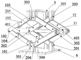
图1为本发明实施例一中一种轻质大负载并联升降机构的结构示意图;1 is a schematic structural diagram of a light-weight and large-load parallel lifting mechanism in
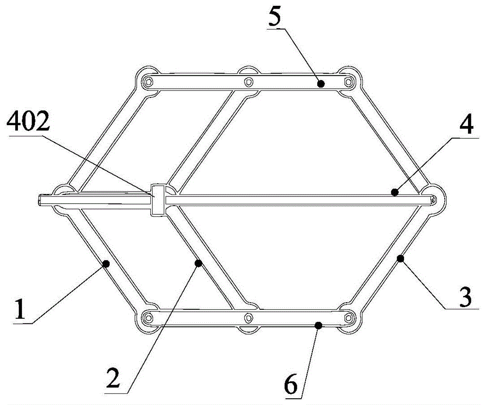
图2为本发明实施例一中一种轻质大负载并联升降机构的结构原理示意图;FIG. 2 is a schematic structural principle diagram of a light-weight and large-load parallel lifting mechanism in
图3为本发明实施例二中一种轻质大负载并联升降机构的结构原理示意图;3 is a schematic structural principle diagram of a light-weight and large-load parallel lifting mechanism in
图4为本发明实施例三中一种轻质大负载并联升降机构的结构原理示意图;4 is a schematic structural principle diagram of a light-weight and large-load parallel lifting mechanism in
图5为本发明实施例四中一种轻质大负载并联升降机构的结构原理示意图;5 is a schematic structural principle diagram of a light-weight and large-load parallel lifting mechanism in
图6为本发明实施例五中一种轻质大负载并联升降机构的结构原理示意图;6 is a schematic structural principle diagram of a light-weight and large-load parallel lifting mechanism in
图7为本发明实施例六中一种轻质大负载并联升降机构的结构示意图;7 is a schematic structural diagram of a light-weight and large-load parallel lifting mechanism in
图8为本发明实施例六中一种轻质大负载并联升降机构的结构原理示意图。FIG. 8 is a schematic structural principle diagram of a light-weight and large-load parallel lifting mechanism according to the sixth embodiment of the present invention.
图中:1为第一举升支链,101为第一举升支链转动副Ⅰ,102为第一举升支链转动副Ⅱ,103为第一举升支链转动副Ⅲ,104为第一举升支链连杆Ⅰ,105为第一举升支链连杆Ⅱ;2为第二举升支链,201为第二举升支链转动副Ⅰ,202为第二举升支链转动副Ⅱ,203为第二举升支链转动副Ⅲ,204为第二举升支链连杆Ⅰ,205为第二举升支链连杆Ⅱ;3为第三举升支链,31为第三举升支链Ⅰ,32为第三举升支链Ⅱ,301为第三举升支链转动副Ⅰ,302为第三举升支链转动副Ⅱ,303为第三举升支链转动副Ⅲ,304为第三举升支链连杆Ⅰ,305为第三举升支链连杆Ⅱ;4为约束支链,401为约束支链连杆Ⅰ,402为移动副,403为约束支链连杆Ⅱ;5为平台;6为底座。In the figure: 1 is the first lifting branch, 101 is the first lifting branch rotating pair I, 102 is the first lifting branch rotating pair II, 103 is the first lifting branch rotating pair III, 104 is the first lifting branch rotating pair The first lifting branch link I, 105 is the first lifting branch link II; 2 is the second lifting branch, 201 is the second lifting branch rotation pair I, and 202 is the second lifting branch Chain rotation pair II, 203 is the second lifting branch rotation pair III, 204 is the second lifting branch link I, 205 is the second lifting branch link II; 3 is the third lifting branch, 31 is the third lifting branch I, 32 is the third lifting branch II, 301 is the third lifting branch rotating pair I, 302 is the third lifting branch rotating pair II, and 303 is the third lifting branch Branch rotation pair III, 304 is the third lifting branch link I, 305 is the third lifting branch link II; 4 is the restraining branch, 401 is the restraining branch link I, 402 is the moving pair, 403 is the constraining branch link II; 5 is the platform; 6 is the base.
具体实施方式Detailed ways
为了使本发明的目的、技术方案和优点更加清楚,下面结合附图和具体实施例对本发明进行详细描述。In order to make the objectives, technical solutions and advantages of the present invention clearer, the present invention will be described in detail below with reference to the accompanying drawings and specific embodiments.
实施例一Example 1
如图1所示,本发明的实施例一中提供的一种轻质大负载并联升降机构,包括约束支链4、平台5、底座6及多组举升支链,其中平台5设置于底座6的上方,且通过多组举升支链与底座6铰接;约束支链4设置于平台5和底座6之间,具有移动副402;多组举升支链分布在约束支链4的移动副402两侧,且与约束支链4铰接。As shown in FIG. 1 , a light-weight and large-load parallel lifting mechanism provided in the first embodiment of the present invention includes a
进一步地,约束支链4与底座6和平台5平行,可驱动移动副402使得平台5向上移动,或驱动任意一举升支链的任意一个转动副,可驱动平台5向上移动。Further, the constraining
如图2所示,本发明的实施例中,约束支链4包括通过移动副402连接的约束支链连杆Ⅰ401和约束支链连杆Ⅱ403,约束支链连杆Ⅰ401和约束支链连杆Ⅱ403在水平内可相对移动。As shown in FIG. 2 , in the embodiment of the present invention, the
本发明的实施例中,多组举升支链包括第一举升支链1、第二举升支链2及第三举升支链3,其中第一举升支链1和第二举升支链2平行设置,且均与约束支链连杆Ⅰ401铰接;第三举升支链3与约束支链连杆Ⅱ403铰接。In the embodiment of the present invention, the multiple groups of lifting branches include a
本发明的实施例中,第一举升支链1包括第一举升支链连杆Ⅰ104和第一举升支链连杆Ⅱ105;第二举升支链2包括第二举升支链连杆Ⅰ204和第二举升支链连杆Ⅱ205;第一举升支链连杆Ⅰ104和第二举升支链连杆Ⅰ204平行设置于约束支链连杆Ⅰ401和底座6之间,且下端均与底座6铰接,上端均与约束支链连杆Ⅰ401铰接;第一举升支链连杆Ⅱ105和第二举升支链连杆Ⅱ205平行设置于约束支链连杆Ⅰ401和平台5之间,且下端均与约束支链连杆Ⅰ401铰接,上端均与平台5铰接。In the embodiment of the present invention, the
进一步地,第一举升支链连杆Ⅰ104和第二举升支链连杆Ⅰ204的长度相等;第一举升支链连杆Ⅱ105和第二举升支链连杆Ⅱ205的长度相等。Further, the lengths of the first lifting branch link I104 and the second lifting branch link I204 are the same; the lengths of the first lifting branch link II 105 and the second lifting branch link II 205 are the same.
本发明的实施例中,第三举升支链3包括第三举升支链连杆Ⅰ304和第三举升支链连杆Ⅱ305,其中第三举升支链连杆Ⅰ304的下端与底座6铰接,上端与约束支链连杆Ⅱ403铰接;第三举升支链连杆Ⅱ305的下端与约束支链连杆Ⅱ403铰接,上端与平台5铰接。In the embodiment of the present invention, the third
进一步地,第三举升支链连杆Ⅰ304的长度与第一举升支链连杆Ⅰ104和第二举升支链连杆Ⅰ204的长度相等,且反向设置;第三举升支链连杆Ⅱ305的长度与第一举升支链连杆Ⅱ105和第二举升支链连杆Ⅱ205的长度相等,且反向设置。Further, the length of the third lifting branch link I304 is equal to the length of the first lifting branch link I104 and the second lifting branch link I204, and is arranged in the opposite direction; The length of the rod II 305 is equal to the lengths of the first lifting branch link II 105 and the second lifting branch link II 205, and they are arranged in opposite directions.
具体地,第一举升支链连杆Ⅰ104的下端通过第一举升支链转动副Ⅰ101与底座6连接,第一举升支链连杆Ⅰ104的上端和第一举升支链连杆Ⅱ105的下端通过第一举升支链转动副Ⅱ102与约束支链连杆Ⅰ401连接,第一举升支链连杆Ⅱ105的上端通过第一举升支链转动副Ⅲ103与平台5连接。第二举升支链连杆Ⅰ204的下端通过第二举升支链转动副Ⅰ201与底座6连接,第二举升支链连杆Ⅰ204的上端和第二举升支链连杆Ⅱ205的下端通过第二举升支链转动副Ⅱ202与约束支链连杆Ⅰ401连接,第二举升支链连杆Ⅱ205的上端通过第二举升支链转动副Ⅲ203与平台5连接。第三举升支链连杆Ⅰ304的下端通过第三举升支链转动副Ⅰ301与底座6连接,第三举升支链连杆Ⅰ304的上端和第三举升支链连杆Ⅱ305的下端通过第三举升支链转动副Ⅱ302与约束支链连杆Ⅱ403连接,第三举升支链连杆Ⅱ305的上端通过第三举升支链转动副Ⅲ303与平台5连接。其中第一举升支链转动副Ⅰ101、第二举升支链转动副Ⅰ201及第三举升支链转动副Ⅰ301的轴线平行,且均位于同一平面内;第一举升支链转动副Ⅱ102、第二举升支链转动副Ⅱ202及第三举升支链转动副Ⅱ302的轴线平行,且均位于同一平面内;第一举升支链转动副Ⅲ103、第二举升支链转动副Ⅲ203及第三举升支链转动副Ⅲ303的轴线平行,且均位于同一平面内。Specifically, the lower end of the first lifting branch link I104 is connected to the
本实施例中,第一举升支链转动副Ⅰ101、第二举升支链转动副Ⅰ201及第三举升支链转动副Ⅰ301由左向右依次设置,即第三举升支链转动副Ⅰ301位于第二举升支链转动副Ⅰ201的外侧;第一举升支链转动副Ⅲ103、第二举升支链转动副Ⅲ203及第三举升支链转动副Ⅲ303由左向右依次设置,即第三举升支链转动副Ⅲ303位于第二举升支链转动副Ⅲ203的外侧。其中以下三段距离相等:第一举升支链转动副Ⅰ101和第二举升支链转动副Ⅰ201之间距离,第一举升支链转动副Ⅱ102和第二举升支链转动副Ⅱ202之间距离,第一举升支链转动副Ⅲ103和第二举升支链转动副Ⅲ203之间距离。具体地,可通过丝杠丝母机构驱动移动副402,使得平台5向上移动,或驱动第一举升支链1、第二举升支链2及第三举升支链3的任意一个转动副,可驱动平台5向上移动。In this embodiment, the first lifting branch rotating pair I101, the second lifting branch rotating pair I201 and the third lifting branch rotating pair I301 are sequentially arranged from left to right, that is, the third lifting branch rotating pair I301 is located on the outside of the second lifting branch rotation pair I201; the first lifting branch rotation pair III103, the second lifting branch rotation pair III203 and the third lifting branch rotation pair III303 are arranged in order from left to right, That is, the third lifting branch chain rotation pair III303 is located outside the second lifting branch chain rotation pair III203. The following three distances are equal: the distance between the first lifting branch rotating pair I101 and the second lifting branch rotating pair I201, the distance between the first lifting branch rotating pair II102 and the second lifting branch rotating pair II202 The distance between the first lifting branch chain rotation pair III103 and the second lifting branch chain rotation pair III203. Specifically, the moving
实施例二
如图3所示,本实施例与实施例一基本相同,不同点在于,第三举升支链转动副Ⅰ301位于第一举升支链转动副Ⅰ101之间第二举升支链转动副Ⅰ201,第三举升支链转动副Ⅲ303位于第一举升支链转动副Ⅲ103和第二举升支链转动副Ⅲ203之间。本实施例的其它结构与实施例一相同,在此不再赘述。As shown in FIG. 3 , this embodiment is basically the same as the first embodiment, the difference is that the third lifting branch rotating pair I301 is located between the first lifting branch rotating pair I101 and the second lifting branch rotating pair I201 , the third lifting branch rotation pair III303 is located between the first lifting branch rotation pair III103 and the second lifting branch rotation pair III203. Other structures of this embodiment are the same as those of the first embodiment, and are not repeated here.
实施例三
如图4所示,本实施例与实施例一基本相同,不同点在于,第三举升支链转动副Ⅰ301与第二举升支链转动副Ⅰ201重合,轴线共线;第三举升支链转动副Ⅲ303与第二举升支链转动副Ⅲ203重合,轴线共线。本实施例的其它结构与实施例一相同,在此不再赘述。As shown in FIG. 4 , this embodiment is basically the same as the first embodiment, the difference is that the third lifting branch rotating pair I301 and the second lifting branch rotating pair I201 are overlapped, and the axes are collinear; The chain rotation pair III303 coincides with the second lifting branch chain rotation pair III203, and the axes are collinear. Other structures of this embodiment are the same as those of the first embodiment, and are not repeated here.
实施例四
如图5所示,本实施例与实施例一基本相同,不同点在于,第三举升支链转动副Ⅰ301与第一举升支链转动副Ⅰ101重合,轴线共线;第三举升支链转动副Ⅲ303与第一举升支链转动副Ⅲ103重合,轴线共线。本实施例的其它结构与实施例一相同,在此不再赘述。As shown in FIG. 5, this embodiment is basically the same as the first embodiment, the difference is that the third lifting branch rotating pair I301 and the first lifting branch rotating pair I101 overlap, and the axes are collinear; The chain rotation pair III303 coincides with the first lifting branch chain rotation pair III103, and the axes are collinear. Other structures of this embodiment are the same as those of the first embodiment, and are not repeated here.
实施例五
如图6所示,本实施例与实施例一基本相同,不同点在于,第三举升支链转动副Ⅰ301位于第一举升支链转动副Ⅰ101的外侧,即第一举升支链转动副Ⅰ101位于第三举升支链转动副Ⅰ301和第二举升支链转动副Ⅰ201之间;第三举升支链转动副Ⅲ303位于第一举升支链转动副Ⅲ103的外侧,即第一举升支链转动副Ⅲ103位于第三举升支链转动副Ⅲ303和第二举升支链转动副Ⅲ203之间。本实施例的其它结构与实施例一相同,在此不再赘述。As shown in FIG. 6 , this embodiment is basically the same as the first embodiment, the difference is that the third lifting branch rotation pair I301 is located outside the first lifting branch rotation pair I101, that is, the first lifting branch rotates The pair I101 is located between the third lifting branch rotating pair I301 and the second lifting branch rotating pair I201; the third lifting branch rotating pair III303 is located outside the first lifting branch rotating pair III103, that is, the first The lifting branch rotation pair III103 is located between the third lifting branch rotation pair III303 and the second lifting branch rotation pair III203. Other structures of this embodiment are the same as those of the first embodiment, and are not repeated here.
实施例六
如图7-8所示,本实施例与实施例二基本相同,不同点在于,第三举升支链3为两组,即包括第三举升支链Ⅰ31和第三举升支链Ⅱ32,第三举升支链Ⅰ31和第三举升支链Ⅱ32平行设置,且第一举升支链1和第二举升支链2位于第三举升支链Ⅰ31和第三举升支链Ⅱ32之间。As shown in Figures 7-8, this embodiment is basically the same as the second embodiment, the difference is that the
本实施例中,通过构型及尺寸相同的第三举升支链Ⅰ31和第三举升支链Ⅱ32组成空间举升构型,第三举升支链Ⅰ31和第三举升支链Ⅱ32共同起到举升的作用,同时增加了抗重力矩能力。In this embodiment, a space lifting configuration is formed by the third lifting branch I31 and the third lifting branch II32 having the same configuration and size, and the third lifting branch I31 and the third lifting branch II32 share the same Play the role of lifting, while increasing the anti-gravity moment capacity.
本发明的实施例中,第一举升支链1和第二举升支链2与平台5、底座6及约束支链4围成两级平行四杆机构支链,具有两个平移运动自由度。三举升支链3和约束支链4一同约束两级平行四杆机构的一个平移自由度,在非奇异位形下,使得平台只有举升方向平移自由度,可通过驱动第一举升支链1、第二举升支链2及三举升支链3的转动副,或驱动约束支链4的移动副402实现驱动平台5升降。三举升支链3的第三举升支链转动副Ⅰ301在满足前述要求下,可布置在第一举升支链转动副Ⅰ101和第二举升支链转动副Ⅰ201的左侧、中间、右侧,或与第一举升支链转动副Ⅰ101和第二举升支链转动副Ⅰ201轴线重合。三举升支链3可采用并联结构获得,得到单驱动空间举升机构。本发明运动可使用丝杠驱动,承载能力大,响应速度快,便于使用电机驱动控制。In the embodiment of the present invention, the
本发明对重力及重力引起的重力矩承受能力较强,可在支链构型不变的情况下延长平台尺寸以扩大工作面。本发明可集成性好,易于集成其他运动机构,在平台上安装转动关节或移动关节等,可实现机构的综合,获得高载荷能力的多自由度机构。The invention has strong bearing capacity to gravity and gravity moment caused by gravity, and can extend the size of the platform to enlarge the working surface under the condition that the branched chain configuration remains unchanged. The invention has good integratability, is easy to integrate other motion mechanisms, and installs rotating joints or moving joints on the platform, which can realize the synthesis of mechanisms and obtain a multi-degree-of-freedom mechanism with high load capacity.
以上所述仅为本发明的实施方式,并非用于限定本发明的保护范围。凡在本发明的精神和原则之内所作的任何修改、等同替换、改进、扩展等,均包含在本发明的保护范围内。The above descriptions are merely embodiments of the present invention, and are not intended to limit the protection scope of the present invention. Any modification, equivalent replacement, improvement, expansion, etc. made within the spirit and principle of the present invention are included in the protection scope of the present invention.
Claims (10)
Priority Applications (1)
| Application Number | Priority Date | Filing Date | Title |
|---|---|---|---|
| CN202110294098.6A CN115108490A (en) | 2021-03-19 | 2021-03-19 | Light heavy-load parallel lifting mechanism |
Applications Claiming Priority (1)
| Application Number | Priority Date | Filing Date | Title |
|---|---|---|---|
| CN202110294098.6A CN115108490A (en) | 2021-03-19 | 2021-03-19 | Light heavy-load parallel lifting mechanism |
Publications (1)
| Publication Number | Publication Date |
|---|---|
| CN115108490A true CN115108490A (en) | 2022-09-27 |
Family
ID=83324211
Family Applications (1)
| Application Number | Title | Priority Date | Filing Date |
|---|---|---|---|
| CN202110294098.6A Pending CN115108490A (en) | 2021-03-19 | 2021-03-19 | Light heavy-load parallel lifting mechanism |
Country Status (1)
| Country | Link |
|---|---|
| CN (1) | CN115108490A (en) |
Citations (3)
| Publication number | Priority date | Publication date | Assignee | Title |
|---|---|---|---|---|
| DE29518420U1 (en) * | 1995-09-09 | 1996-01-18 | Thüringer Fleischereimaschinen GmbH, 99310 Arnstadt | Lifting device for seating, lying or storage areas |
| CN109019409A (en) * | 2018-09-21 | 2018-12-18 | 南京理工大学 | A kind of multi link lifting device |
| CN214828700U (en) * | 2021-03-19 | 2021-11-23 | 中国科学院沈阳自动化研究所 | Lightweight and large load parallel lifting mechanism |
-
2021
- 2021-03-19 CN CN202110294098.6A patent/CN115108490A/en active Pending
Patent Citations (3)
| Publication number | Priority date | Publication date | Assignee | Title |
|---|---|---|---|---|
| DE29518420U1 (en) * | 1995-09-09 | 1996-01-18 | Thüringer Fleischereimaschinen GmbH, 99310 Arnstadt | Lifting device for seating, lying or storage areas |
| CN109019409A (en) * | 2018-09-21 | 2018-12-18 | 南京理工大学 | A kind of multi link lifting device |
| CN214828700U (en) * | 2021-03-19 | 2021-11-23 | 中国科学院沈阳自动化研究所 | Lightweight and large load parallel lifting mechanism |
Similar Documents
| Publication | Publication Date | Title |
|---|---|---|
| CN103552948B (en) | A kind of slide plate Aerial Work LT and slide plate and slide plate travel line | |
| ES2758103T3 (en) | Lifting device | |
| US20140374680A1 (en) | Screw-driven lifting platform | |
| CN102292278A (en) | Lifting mechanism and medical bed device | |
| CN100563946C (en) | Two degrees of freedom mobile parallel decoupling mechanism | |
| CN202542490U (en) | Transporting and stacking robot | |
| CN112125211B (en) | Lifting device | |
| CN212893697U (en) | Lifting device and carrying equipment | |
| CN105600710A (en) | A new type of satellite side plate-mounted star frame vehicle | |
| CN214828700U (en) | Lightweight and large load parallel lifting mechanism | |
| CN104131722B (en) | A kind of dodge gate posture reach rotary parking apparatus | |
| CN108609197B (en) | Skid type helicopter ground omnidirectional moving device | |
| CN106627319A (en) | Roller type all-directional traveling platform cart | |
| CN106315454B (en) | A linear lifting mechanism | |
| CN108083144A (en) | Complete automatically controlled lifting telescopic arm | |
| CN115108490A (en) | Light heavy-load parallel lifting mechanism | |
| CN104326202B (en) | A kind of tiered warehouse facility | |
| RU145085U1 (en) | ASSEMBLY LIFT | |
| CN106944988A (en) | A kind of two-dimensional movement workbench for splicing detection for face shape | |
| CN101863023A (en) | A Two-DOF Parallel Mechanism in Planar Polar Coordinates | |
| CN105952163A (en) | Jacking gliding device and method | |
| CN103231364A (en) | Three-freedom-degree and four-freedom-degree parallel mechanism | |
| CN205087808U (en) | Hoist mechanism and have this hoist mechanism's transportation equipment | |
| CN203938072U (en) | Tiered warehouse facility | |
| CN203319634U (en) | A hydraulic lifting platform with longitudinal and horizontal moving device |
Legal Events
| Date | Code | Title | Description |
|---|---|---|---|
| PB01 | Publication | ||
| PB01 | Publication | ||
| SE01 | Entry into force of request for substantive examination | ||
| SE01 | Entry into force of request for substantive examination |