CN115106245A - Batch coating equipment and batch coating method - Google Patents
Batch coating equipment and batch coating method Download PDFInfo
- Publication number
- CN115106245A CN115106245A CN202110291066.0A CN202110291066A CN115106245A CN 115106245 A CN115106245 A CN 115106245A CN 202110291066 A CN202110291066 A CN 202110291066A CN 115106245 A CN115106245 A CN 115106245A
- Authority
- CN
- China
- Prior art keywords
- liquid
- coating
- coated
- examples
- fixing
- Prior art date
- Legal status (The legal status is an assumption and is not a legal conclusion. Google has not performed a legal analysis and makes no representation as to the accuracy of the status listed.)
- Granted
Links
- 238000000576 coating method Methods 0.000 title claims abstract description 364
- 239000011248 coating agent Substances 0.000 title claims abstract description 347
- 239000007788 liquid Substances 0.000 claims abstract description 410
- 230000007246 mechanism Effects 0.000 claims abstract description 225
- 238000001802 infusion Methods 0.000 claims abstract description 57
- 238000002347 injection Methods 0.000 claims abstract description 54
- 239000007924 injection Substances 0.000 claims abstract description 54
- 238000000034 method Methods 0.000 claims description 12
- 238000007654 immersion Methods 0.000 claims description 3
- 210000005056 cell body Anatomy 0.000 claims 1
- 239000000243 solution Substances 0.000 description 110
- 239000010408 film Substances 0.000 description 77
- LFQSCWFLJHTTHZ-UHFFFAOYSA-N Ethanol Chemical compound CCO LFQSCWFLJHTTHZ-UHFFFAOYSA-N 0.000 description 32
- 239000012530 fluid Substances 0.000 description 20
- 230000006872 improvement Effects 0.000 description 18
- 239000007888 film coating Substances 0.000 description 15
- 238000009501 film coating Methods 0.000 description 15
- 239000007789 gas Substances 0.000 description 11
- 238000001035 drying Methods 0.000 description 10
- 235000019441 ethanol Nutrition 0.000 description 10
- 230000037452 priming Effects 0.000 description 10
- 238000010586 diagram Methods 0.000 description 9
- 230000008569 process Effects 0.000 description 8
- 210000000746 body region Anatomy 0.000 description 7
- 239000000463 material Substances 0.000 description 6
- WQZGKKKJIJFFOK-GASJEMHNSA-N Glucose Natural products OC[C@H]1OC(O)[C@H](O)[C@@H](O)[C@@H]1O WQZGKKKJIJFFOK-GASJEMHNSA-N 0.000 description 5
- 239000008103 glucose Substances 0.000 description 5
- 230000008021 deposition Effects 0.000 description 4
- 239000008279 sol Substances 0.000 description 4
- 239000008280 blood Substances 0.000 description 3
- 210000004369 blood Anatomy 0.000 description 3
- 238000004891 communication Methods 0.000 description 3
- 238000012545 processing Methods 0.000 description 3
- 239000000523 sample Substances 0.000 description 3
- 238000001179 sorption measurement Methods 0.000 description 3
- IJGRMHOSHXDMSA-UHFFFAOYSA-N Atomic nitrogen Chemical compound N#N IJGRMHOSHXDMSA-UHFFFAOYSA-N 0.000 description 2
- 230000004308 accommodation Effects 0.000 description 2
- 239000002216 antistatic agent Substances 0.000 description 2
- 230000009286 beneficial effect Effects 0.000 description 2
- 230000015572 biosynthetic process Effects 0.000 description 2
- 238000007598 dipping method Methods 0.000 description 2
- 230000000694 effects Effects 0.000 description 2
- 238000004519 manufacturing process Methods 0.000 description 2
- 206010033675 panniculitis Diseases 0.000 description 2
- 238000007789 sealing Methods 0.000 description 2
- 238000003756 stirring Methods 0.000 description 2
- 210000004304 subcutaneous tissue Anatomy 0.000 description 2
- 229910000838 Al alloy Inorganic materials 0.000 description 1
- 229910000640 Fe alloy Inorganic materials 0.000 description 1
- 229910000990 Ni alloy Inorganic materials 0.000 description 1
- 229910001069 Ti alloy Inorganic materials 0.000 description 1
- 238000009825 accumulation Methods 0.000 description 1
- 230000009471 action Effects 0.000 description 1
- 230000008878 coupling Effects 0.000 description 1
- 238000010168 coupling process Methods 0.000 description 1
- 238000005859 coupling reaction Methods 0.000 description 1
- 230000028993 immune response Effects 0.000 description 1
- 238000002513 implantation Methods 0.000 description 1
- 239000011261 inert gas Substances 0.000 description 1
- 230000014759 maintenance of location Effects 0.000 description 1
- 239000011159 matrix material Substances 0.000 description 1
- 238000012986 modification Methods 0.000 description 1
- 230000004048 modification Effects 0.000 description 1
- 238000012544 monitoring process Methods 0.000 description 1
- 229910052757 nitrogen Inorganic materials 0.000 description 1
- 230000009467 reduction Effects 0.000 description 1
- 239000007787 solid Substances 0.000 description 1
- 239000002904 solvent Substances 0.000 description 1
- 239000010935 stainless steel Substances 0.000 description 1
- 229910001220 stainless steel Inorganic materials 0.000 description 1
- 239000010409 thin film Substances 0.000 description 1
- 239000012780 transparent material Substances 0.000 description 1
- 239000002699 waste material Substances 0.000 description 1
- XLYOFNOQVPJJNP-UHFFFAOYSA-N water Substances O XLYOFNOQVPJJNP-UHFFFAOYSA-N 0.000 description 1
Images


Classifications
-
- B—PERFORMING OPERATIONS; TRANSPORTING
- B05—SPRAYING OR ATOMISING IN GENERAL; APPLYING FLUENT MATERIALS TO SURFACES, IN GENERAL
- B05C—APPARATUS FOR APPLYING FLUENT MATERIALS TO SURFACES, IN GENERAL
- B05C3/00—Apparatus in which the work is brought into contact with a bulk quantity of liquid or other fluent material
- B05C3/02—Apparatus in which the work is brought into contact with a bulk quantity of liquid or other fluent material the work being immersed in the liquid or other fluent material
- B05C3/09—Apparatus in which the work is brought into contact with a bulk quantity of liquid or other fluent material the work being immersed in the liquid or other fluent material for treating separate articles
- B05C3/10—Apparatus in which the work is brought into contact with a bulk quantity of liquid or other fluent material the work being immersed in the liquid or other fluent material for treating separate articles the articles being moved through the liquid or other fluent material
-
- B—PERFORMING OPERATIONS; TRANSPORTING
- B05—SPRAYING OR ATOMISING IN GENERAL; APPLYING FLUENT MATERIALS TO SURFACES, IN GENERAL
- B05C—APPARATUS FOR APPLYING FLUENT MATERIALS TO SURFACES, IN GENERAL
- B05C11/00—Component parts, details or accessories not specifically provided for in groups B05C1/00 - B05C9/00
- B05C11/10—Storage, supply or control of liquid or other fluent material; Recovery of excess liquid or other fluent material
- B05C11/1002—Means for controlling supply, i.e. flow or pressure, of liquid or other fluent material to the applying apparatus, e.g. valves
-
- B—PERFORMING OPERATIONS; TRANSPORTING
- B05—SPRAYING OR ATOMISING IN GENERAL; APPLYING FLUENT MATERIALS TO SURFACES, IN GENERAL
- B05C—APPARATUS FOR APPLYING FLUENT MATERIALS TO SURFACES, IN GENERAL
- B05C13/00—Means for manipulating or holding work, e.g. for separate articles
- B05C13/02—Means for manipulating or holding work, e.g. for separate articles for particular articles
-
- B—PERFORMING OPERATIONS; TRANSPORTING
- B05—SPRAYING OR ATOMISING IN GENERAL; APPLYING FLUENT MATERIALS TO SURFACES, IN GENERAL
- B05D—PROCESSES FOR APPLYING FLUENT MATERIALS TO SURFACES, IN GENERAL
- B05D1/00—Processes for applying liquids or other fluent materials
- B05D1/18—Processes for applying liquids or other fluent materials performed by dipping
-
- B—PERFORMING OPERATIONS; TRANSPORTING
- B05—SPRAYING OR ATOMISING IN GENERAL; APPLYING FLUENT MATERIALS TO SURFACES, IN GENERAL
- B05C—APPARATUS FOR APPLYING FLUENT MATERIALS TO SURFACES, IN GENERAL
- B05C3/00—Apparatus in which the work is brought into contact with a bulk quantity of liquid or other fluent material
- B05C3/20—Apparatus in which the work is brought into contact with a bulk quantity of liquid or other fluent material for applying liquid or other fluent material only at particular parts of the work
-
- B—PERFORMING OPERATIONS; TRANSPORTING
- B05—SPRAYING OR ATOMISING IN GENERAL; APPLYING FLUENT MATERIALS TO SURFACES, IN GENERAL
- B05D—PROCESSES FOR APPLYING FLUENT MATERIALS TO SURFACES, IN GENERAL
- B05D2258/00—Small objects (e.g. screws)
Landscapes
- Coating Apparatus (AREA)
Abstract
The utility model discloses a batch coating equipment and a batch coating method for improving consistency, which comprises a fixing mechanism, a liquid containing mechanism, a liquid injection mechanism and a control device, wherein the fixing mechanism is provided with a plurality of fixing parts for fixing a workpiece to be coated, the liquid containing mechanism is provided with a plurality of liquid tanks which are arranged side by side and have the same shape for containing coating liquid, the liquid injection mechanism is provided with a liquid storage part for containing the coating liquid and an infusion part which is communicated with the liquid storage part and is used for supplying the coating liquid, and the control device controls the liquid injection mechanism and the liquid containing mechanism to move relatively so that the infusion part aligns with the liquid tank and controls the infusion part to supply the coating liquid with a preset volume into the liquid tank; and the control device controls the liquid containing mechanism and the fixing mechanism to move relatively so that the workpiece to be coated, which is fixed on the fixing mechanism, is immersed into the coating liquid in the liquid tank and separated from the coating liquid in the liquid tank, and a coating film is formed on the workpiece to be coated. According to the present disclosure, a mass coating apparatus and a mass coating method that improve uniformity can be provided.
Description
Technical Field
The disclosure relates to a batch coating apparatus and a batch coating method.
Background
In the field of medical devices, since medical devices are generally in contact with the human body, they are produced by a biocompatible treatment. For example, when an implantable blood glucose monitor is used for blood glucose monitoring, a sensing probe of the blood glucose monitor is often buried in subcutaneous tissue of a subject, and a biocompatible film is usually coated on a working electrode of the sensing probe in order to reduce an immune response caused by the implantation of the sensing probe in the subcutaneous tissue.
In the prior art, a pull-up coating apparatus generally immerses a sensor electrode in a sol prepared in advance, then pulls the sensor electrode out of the sol to form a uniform liquid film on the surface of the sensor electrode, and forms a uniform thin film on the surface of the sensor electrode soaked by the sol as a solvent in the sol rapidly evaporates.
However, there are some problems in the batch coating production process, and because of more variables affecting parameters in the coating process, the differences of the film thickness, opacity, color and the like formed on the surface of each sensor electrode may be large, and it is difficult to ensure the consistency of the coating. Therefore, a coating apparatus capable of improving uniformity and coating films in mass production is required.
Disclosure of Invention
The present disclosure has been made in view of the above-described state of the art, and an object thereof is to provide a mass coating apparatus and a mass coating method capable of improving coating film uniformity.
To this end, the present disclosure provides, in a first aspect, a batch coating apparatus, which includes a fixing mechanism, a liquid containing mechanism, a liquid injection mechanism, and a control device; the fixing mechanism is provided with a plurality of fixing parts for fixing workpieces to be coated; the liquid containing mechanism is provided with a plurality of liquid tanks which are arranged side by side and are used for containing coating liquid in the same shape, each liquid tank comprises a tank body part with an accommodating space and an opening part connected with the tank body part, the cross sectional area of the opening part is larger than that of the tank body part, and the liquid containing mechanism and the fixing mechanism can move relatively; the liquid injection mechanism is provided with a liquid storage part for containing coating liquid and an infusion part which is communicated with the liquid storage part and used for supplying the coating liquid, and the liquid injection mechanism and the liquid containing mechanism can move relatively; the control device is configured to control at least the relative movement between the fixing mechanism and the liquid containing mechanism and the relative movement between the liquid containing mechanism and the liquid injection mechanism, and control the liquid injection mechanism to supply the coating liquid through the infusion part; when a workpiece to be coated, which is fixed on the fixing mechanism, is coated, the control device controls the liquid injection mechanism and the liquid containing mechanism to move relatively so that the infusion part is aligned with the liquid tank and controls the infusion part to supply a coating liquid with a preset volume into the liquid tank; and the control device controls the liquid containing mechanism and the fixing mechanism to move relatively so that the workpiece to be coated, which is fixed on the fixing mechanism, is immersed into the coating liquid in the liquid tank and separated from the coating liquid in the liquid tank, and a coating film with a preset thickness is formed on the workpiece to be coated.
In the present disclosure, by providing a plurality of fixing portions at the fixing mechanism and arranging a plurality of liquid tanks at the liquid containing mechanism, it is possible to perform batch coating of a workpiece to be coated; by arranging the liquid tanks to have the same shape and contain the coating liquid with a predetermined volume, the workpiece to be coated, which is fixed on the fixing mechanism, is immersed into the coating liquid in the liquid tanks and separated from the coating liquid in the liquid tanks, and a coating film with a predetermined thickness is formed on the workpiece to be coated, so that the uniformity of coating can be improved.
In addition, in the batch coating apparatus according to the first aspect of the present disclosure, optionally, the predetermined volume is not greater than the volume of the accommodating space, and the predetermined volume is less than or equal to 100 μ L.
In the mass coating apparatus according to the first aspect of the present disclosure, the opening portion may have a funnel shape that tapers from an upper end to a lower end, and the main body portion may be connected to the lower end of the opening portion. Therefore, the utilization rate of the coating liquid can be improved.
In addition, in the mass coating apparatus according to the first aspect of the present disclosure, the tank portion may optionally include a main body region having a cylindrical shape and a bottom region having a hemispherical shape. Thereby, it can be facilitated to form a uniform coating film on the surface of the workpiece to be coated.
In addition, in the mass coating apparatus according to the first aspect of the present disclosure, optionally, the plurality of liquid tanks of the liquid containing mechanism are arranged in a matrix.
In addition, in the mass coating apparatus according to the first aspect of the present disclosure, the apparatus may further include a liquid injection chamber in which the liquid injection mechanism supplies the coating liquid to the liquid containing mechanism, and a coating chamber in which the work to be coated, which is fixed to the fixing mechanism, is immersed in the coating liquid in the liquid tank.
In addition, in the mass coating apparatus according to the first aspect of the present disclosure, the injection mechanism may further include a piston disposed in the reservoir portion and movable in a longitudinal direction of the reservoir portion, the piston may be connected to an actuating member, the actuating member may actuate the piston to move in the longitudinal direction of the reservoir portion, the actuating member may be connected to the control device and may be controlled by the control device, and the control device may control an actuating distance and an actuating direction of the actuating member to supply a predetermined volume of the coating solution to the liquid tank via the infusion portion. This can contribute to improvement in coating film uniformity.
In addition, in the mass coating apparatus according to the first aspect of the present disclosure, optionally, the workpiece to be coated has a first fixing area, a second fixing area, and a region to be coated, where the first fixing area and the second fixing area are located on the same plane and are connected in sequence, the first fixing area and the second fixing area are in a sheet shape, and the region to be coated is in a needle shape. Thereby, the workpiece to be coated can be conveniently fixed.
In addition, in the mass coating apparatus according to the first aspect of the present disclosure, optionally,
the fixing part is provided with a first limiting groove matched with the first fixing area and a second limiting groove matched with the second fixing area, the first limiting groove is matched with the first fixing area to limit the area to be coated in the vertical direction, and the second limiting groove is matched with the second fixing area to limit the area to be coated in the horizontal direction, so that the area to be coated is limited at a preset position. This can contribute to improvement in coating film uniformity.
Further, a second aspect of the present disclosure provides a batch coating method including preparing a plurality of liquid tanks having the same shape, and supplying a predetermined volume of coating solution to each of the liquid tanks; preparing a plurality of workpieces to be coated, simultaneously immersing each workpiece to be coated into the coating liquid in each liquid tank respectively and separating from the coating liquid in each liquid tank, wherein the immersion depths of the workpieces to be coated into the coating liquid are consistent, so that a coating film with a preset thickness is formed on each workpiece to be coated; the liquid tank comprises a tank body part with an accommodating space and an opening part connected with the tank body part, and the cross sectional area of the opening part is larger than that of the tank body part.
In the method, the plurality of liquid tanks with the same shape are arranged, and the depths of the workpieces to be coated, which are immersed in the coating liquid, are consistent, so that the workpieces to be coated can be coated in batches, and the coating consistency can be improved.
According to the present disclosure, a batch coating apparatus and a batch coating method capable of improving consistency can be provided.
Drawings
The disclosure will now be explained in further detail by way of example only with reference to the accompanying drawings, in which:
fig. 1 is a schematic diagram showing a film coating apparatus according to an example of the present disclosure.
Fig. 2 is a schematic view showing the overall configuration of a film coating apparatus according to an example of the present disclosure.
Fig. 3 is a schematic structural view showing a workpiece to be film-coated according to an example of the present disclosure.
Fig. 4 is a schematic structural view showing a fixing mechanism according to an example of the present disclosure.
Fig. 5 is a schematic diagram illustrating a fixing part according to an example of the present disclosure.
Fig. 6 is a schematic diagram illustrating a liquid containing mechanism according to an example of the present disclosure.
Fig. 7 is a schematic view showing the liquid bath shown in fig. 6.
Fig. 8A is a schematic diagram illustrating a workpiece to be coated according to an example of the present disclosure before being immersed in a coating solution in a liquid bath.
Fig. 8B is a schematic view showing a workpiece to be coated with a film according to an example of the present disclosure after being immersed in a coating solution in a liquid bath.
Fig. 9 is a schematic diagram illustrating a priming mechanism according to an example of the present disclosure.
Fig. 10 is a schematic diagram illustrating a liquid filling mechanism according to an example of the present disclosure supplying a coating solution to a liquid tank.
Fig. 11 is a schematic flow chart illustrating a batch coating method according to an example of the present disclosure.
Reference numerals are as follows:
1 … coating equipment, 2 … workpiece to be coated, 11 … fixing mechanism, 12 … liquid containing mechanism, 13 … liquid injection mechanism, 14 … control device and 15 … driving mechanism
Detailed Description
Hereinafter, preferred embodiments of the present disclosure will be described in detail with reference to the accompanying drawings. In the following description, the same components are denoted by the same reference numerals, and redundant description thereof is omitted. The drawings are schematic and the ratio of the dimensions of the components and the shapes of the components may be different from the actual ones.
It is noted that the terms "comprises" and "comprising," and any variations thereof, in this disclosure, such that a process, method, system, article, or apparatus that comprises or has a list of steps or elements is not necessarily limited to those steps or elements expressly listed, but may include or have other steps or elements not expressly listed or inherent to such process, method, article, or apparatus.
In addition, the headings and the like referred to in the following description of the present disclosure are not intended to limit the content or scope of the present disclosure, but merely serve as a reminder for reading. Such a subtitle should neither be understood as a content for segmenting an article, nor should the content under the subtitle be limited to only the scope of the subtitle.
The disclosure relates to a batch coating device capable of improving consistency, which is a coating device for coating a workpiece to be coated. The mass coating equipment capable of improving the consistency can be simply called as "coating equipment" or "equipment", and the coating equipment can carry out mass coating and is beneficial to improving the coating consistency of workpieces to be coated.
The present disclosure relates to a mass coating apparatus 1 capable of improving consistency by immersing a workpiece 2 to be coated in a coating solution and by separating the workpiece 2 from the coating solution to coat the workpiece. The operation of immersing the work 2 to be coated in the coating solution may be referred to as "immersing", and the operation of separating the work 2 to be coated from the coating solution may be referred to as "pulling". In other words, the coating apparatus 1 can perform coating by dip-pulling the workpiece 2 to be coated.
Fig. 1 is a schematic view showing a film coating apparatus 1 according to an example of the present disclosure.
Fig. 2 is a schematic view showing the overall configuration of the film coating apparatus 1 according to an example of the present disclosure. The film coating apparatus 1 can be used for coating a plurality of workpieces 2 to be coated.
In the present embodiment, the coating apparatus 1 may include a fixing mechanism 11, a liquid holding mechanism 12, and a liquid injection mechanism 13 (see fig. 2). The fixing mechanism 11 can be used for fixing the workpiece 2 to be coated, the liquid containing mechanism 12 can be used for containing coating liquid, and the liquid injection mechanism 13 can contain the coating liquid and can supply the coating liquid to the liquid containing mechanism 12.
In some examples, the film coating apparatus 1 may further include a control device 14 (see fig. 2). The control device 14 can be used for controlling the relative movement between the fixing mechanism 11 and the liquid containing mechanism 12, the relative movement between the liquid containing mechanism 12 and the liquid injecting mechanism 13 and controlling the liquid injecting mechanism 13 to supply the coating liquid to the liquid containing mechanism 12. In this case, the fixing mechanism 11, the liquid containing mechanism 12, the liquid injecting mechanism 13, and the control device 14 are engaged with each other, thereby facilitating the coating of the workpiece 2 to be coated.
In some examples, the film coating apparatus 1 may further include a drive mechanism 15 (see fig. 1). In some examples, drive mechanism 15 may include a first drive assembly 151, a second drive assembly 152, and a third drive assembly 153 (see fig. 1).
Fig. 3 is a schematic view showing the structure of a workpiece 2 to be film-coated according to an example of the present disclosure.
In some examples, the workpiece 2 to be film-coated may have a first fixing area 21, a second fixing area 22, and a region 23 to be coated with the coating solution, which are substantially coplanar and connected in sequence (see fig. 3).
In some examples, the first fixation area 21 may be sheet-like. In some examples, the second fixation area 22 may be sheet-like. In some examples, the region to be coated 13 may be needle-shaped (see fig. 3). Thereby, the fixing of the work 2 to be film-coated can be facilitated.
In other examples, the shape of the workpiece 2 to be coated is not particularly limited and may be selected according to actual needs. For example, the workpiece 2 to be coated may be in the form of a sheet, a column, or a needle.
In some examples, the connection of the second fixation area 22 to the first fixation area 21 may be a smooth connection (see fig. 3). Thereby, the fixing of the work 2 to be film-coated can be facilitated.
In some examples, the workpiece 2 to be coated may be a working electrode or a micro-electrode of a glucose sensor. Hereinafter, the coating apparatus 1 according to the present embodiment will be described in detail by taking an example of the working electrode of the glucose sensor.
(fixing means 11)
Fig. 4 is a schematic structural view showing a fixing mechanism 11 according to an example of the present disclosure.
In some examples, the fixing mechanism 11 may have a fixing portion 111 (see fig. 4). In some examples, the number of the fixing portions 111 may be one or more. For example, the number of the fixing portions 111 may be 1, 2, 3, 4, 5, 6, 7, or 8. In some examples, the fixing portion 111 may be used to fix the workpiece 2 to be film-coated. In this case, a plurality of works 2 to be film-coated can be fixed by the fixing mechanism 11, so that the plurality of works 2 to be film-coated can be simultaneously film-coated, whereby the works 2 to be film-coated can be film-coated in batches.
In some examples, the plurality of fixtures 111 may be arranged side-by-side (see fig. 4). In some examples, the plurality of fixing parts 111 may be arranged at the same level. In this case, by arranging the plurality of fixing portions 111 at the same level, the plurality of workpieces 2 to be coated can be fixed at the same level, whereby the coating uniformity can be improved. Additionally, in some examples, the relative position of the plurality of fixtures 111 to each other is adjustable. Thereby, the arrangement of the plurality of fixing portions 111 can be adjusted according to actual needs. For example, the plurality of fixing portions 111 may be arranged irregularly, in a height arrangement, or asymmetrically. Thereby, the coating apparatus 1 can be applied to more scenes. For example, the plurality of fixing portions 111 may be arranged in a high-low manner. In this case, a plurality of workpieces 2 to be coated, which are not uniform in length, can be coated by the coating apparatus 1.
In some examples, the securing mechanism 11 may have a securing cleat 112. In some examples, the number of fixation cleats 112 may be one or more. For example, the fixing mechanism 11 may have a fixing jaw 112a, a fixing jaw 112b, and a fixing jaw 112c (see fig. 4).
In some examples, the fixation splint 112 may be substantially regular in shape, such as a cuboid, a cube, a cylinder, or the like. In some examples, such as the example shown in fig. 4, the retaining splint 112 may be a rectangular solid that is substantially flat.
In some examples, the fixation splint 112 may be provided with one or more fixation portions 111. In some examples, a plurality of fixation portions 111 may be arranged side by side on the fixation splint 112 (see fig. 4). In this case, the fixing mechanism 11 can simultaneously fix a plurality of works 2 to be film-coated, and the plurality of works 2 to be film-coated can be fixed on the fixing mechanism 11 at the same level, whereby the uniformity of film coating can be improved.
In some examples, the fixing portion 111 may be welded to the fixing clip 112.
In some examples, two adjacent fixation cleats 112 of the plurality of fixation cleats 112 may be connected using magnetic attraction. For example, in some examples, the fixing clip 112 may have a connection hole 1121 (see fig. 4). In this case, the adjacent two fixing clamps 112 can be magnetically coupled by placing a magnet in the coupling hole 1121. In some examples, the number of the connection holes 1121 may be one or more. In some examples, the plurality of connection holes 1121 may be located on the same horizontal line.
In other examples, the plurality of fixing clips 112 may be connected by a screw structure, and the pitch of the plurality of fixing clips 112 may be adjusted by a screw.
In some examples, adjacent two of the plurality of fixing jaws 112 may have a spacing therebetween that matches the size of the workpiece 2 to be coated.
In some examples, multiple fixation cleats 112 may be placed in parallel. In some examples, multiple stationary cleats 112 may be disposed at the same level. For example, the fixation clamp 112a, the fixation clamp 112b, and the fixation clamp 112c may be located at the same horizontal plane.
In some examples, the stationary jaw 112 may be composed of one or more selected from an aluminum alloy, an iron alloy, stainless steel, a nickel alloy, a titanium alloy, or a cemented carbide.
In some examples, a side-by-side arrangement of a plurality of fixation cleats 112 may form a fixation module 113. For example, the fixing clip 112a, the fixing clip 112b, and the fixing clip 112c may constitute a fixing module 113 (see fig. 4).
In some examples, the fixing portion 111 may have a fixing clip (not shown) for fixing the workpiece 2 to be film-coated.
In some examples, the securing mechanism 11 may include a securing abutment 114 (see fig. 4). In some examples, the fixed abutment 114 may be substantially regular in shape, such as a cuboid, a cube, a cylinder, or the like. For example, the fixed base 114 may have a substantially rectangular parallelepiped shape (see fig. 4).
In addition, in some examples, an end of the fixing splint 112 away from the fixing portion 111 may be connected with a fixing base 114 (see fig. 4).
In addition, in some examples, the fixing clip 112 may be connected with the fixing base 114 by a snap fit structure or a screw structure. In some examples, the fixation abutment 114 can have a plurality of grooves that mate with the fixation splint 112.
In some examples, the fixed base 114 can be connected with the fixed module 113. The fixing module 113 may be composed of a plurality of fixing jaws 112.
In some examples, the fixing module 113 may be rotatably connected with the fixing base 114.
In some examples, the fixing mechanism 11 may be provided with a posture sensor (not shown). The data such as the inclination and the perpendicularity of the horizontal position of the fixing mechanism 11 can be measured by the attitude sensor. In this case, the attitude of the fixing mechanism 11 can be monitored by the attitude sensor, and when the attitude of the fixing mechanism 11 is in a non-preset value, the attitude of the fixing mechanism 11 can be adjusted to fix the plurality of workpieces to be film-coated 2 at predetermined positions, whereby errors in process parameters can be reduced to improve the film coating uniformity of the film coating apparatus 1.
In some examples, the fixing mechanism 11 can fix the workpiece 2 to be coated with a film through the first fixing area 21 and the second fixing area 22, so that the stability of fixing the plurality of workpieces 2 to be coated with a film can be improved, and thus, the difference of process parameters among the plurality of workpieces 2 to be coated with a film can be reduced to improve the uniformity of coating.
Fig. 5 is a schematic diagram illustrating the fixing portion 111 according to the example of the present disclosure.
In some examples, the fixing portion 111 may have a first limit groove 1111 fitted with the first fixing section 21. In some examples, the fixing portion 111 may have a second stopper groove 1112 (see fig. 5) adapted to the second fixing section 22.
In some examples, the first limit groove 1111 may cooperate with the first fixing section 21 to limit the coating region 23 in the vertical direction (see fig. 5) to fix the coating film workpiece 2 in the vertical direction. In this case, an unintended movement of the workpiece 2 to be film-coated in the vertical direction can be reduced.
In some examples, a lower surface of the first limit groove 1111 may interfere with an upper surface of the first fixing section 21 to limit the to-be-coated region 23 in a vertical direction (see fig. 5).
In some examples, the second limiting groove 1112 can cooperate with the second fixing section 22 to limit the coating-ready region 23 in the horizontal direction (see fig. 5) to fix the coating-ready workpiece 2 in the horizontal direction. In this case, an unintended movement of the workpiece 2 to be coated in the horizontal direction can be reduced.
In some examples, the inner surface of the second stopper groove 1112 may interfere with the side surface of the second fixing section 22 to horizontally stopper the region 23 to be coated (see fig. 5).
In some examples, the first position-limiting groove 1111 and the second position-limiting groove 1112 can cooperate with each other. For example, the first limiting grooves 1111 and the second limiting grooves 1112 can cooperate to fix a plurality of workpieces 2 to be coated on the same plane. In this case, the workpiece 2 to be coated can be fixed in two directions by the first limit groove 1111 being engaged with the second limit groove 1112, so that the region 23 to be coated is limited to a predetermined position, whereby the coating uniformity can be advantageously improved.
(liquid holding mechanism 12)
Fig. 6 is a schematic view showing a liquid containing mechanism 12 according to an example of the present disclosure.
In some examples, the liquid holding mechanism 12 may have a liquid tank 121 (see fig. 6). In some examples, the fluid bath 121 may be used to hold coating fluid.
In some examples, the liquid holding mechanism 12 may have one or more liquid baths 121. For example, in the example shown in fig. 6, the liquid containing mechanism 12 may have a liquid tank 121a, a liquid tank 121b, and a liquid tank 121 c. This enables batch coating of the workpiece 2 to be coated.
In some examples, the plurality of fluid baths 121 may be identical in shape. For example, in the embodiment shown in fig. 6, liquid tanks 121a, 121b and 121c may be identical in shape. In this case, when each liquid tank 121 contains the same volume of coating liquid, the liquid level height of each liquid tank 121 can be kept uniform, so that the depth of the workpiece 2 to be coated immersed in the coating liquid in the liquid tank can be kept uniform, thereby being beneficial to improving the coating uniformity.
In other examples, the shape of the plurality of fluid baths 121 may be different.
In some examples, the plurality of fluid baths 121 may be arranged in an array (see fig. 6). In this case, the depth and angle at which the work 2 to be coated is immersed in the coating liquid in each liquid bath 121 can be kept uniform, and thus, the coating uniformity can be advantageously improved.
In some examples, the plurality of fluid baths 121 may be arranged at the same level (see fig. 6). In this case, the depth and angle at which the work 2 to be coated is immersed in the coating liquid in each liquid bath 121 can be kept uniform, and thus, the coating uniformity can be advantageously improved.
In some examples, the arrangement of the liquid bath 121 may be matched with the workpiece 2 to be film-coated and the fixing mechanism 11. For example, in some examples, the number of liquid tanks 121 may coincide with the number of fixing portions 111 of the fixing mechanism 11, a plurality of liquid tanks 121 may be arranged at the same level, and the fixing mechanism 11 may fix the workpiece 2 to be film-coated at the same level. In this case, the workpiece 2 to be coated, which is fixed to the fixing mechanism 11, can be immersed in the coating solution in the liquid bath 121 at a uniform angle and depth, which can be advantageous in improving coating uniformity.
In some examples, the plurality of fluid slots 121 may be integrally formed. In this case, the accuracy of the position between the liquid tanks 121 can be improved to improve the uniformity of the coating film.
In some examples, the plurality of fluid baths 121 may be independent of each other. In this case, the respective liquid tanks 121 can be advantageously adjusted in position independently of each other.
In some examples, multiple fluid baths 121 may constitute a fluid bath module 122. For example, the number of the liquid tanks 121 constituting the liquid tank module 122 may be 3, 5, 8, 10, or 20. In the example shown in fig. 6, the liquid tank 121a, the liquid tank 121b, and the liquid tank 121c may constitute a liquid tank module 122.
In some examples, the liquid containing mechanism 12 may have 100 liquid tanks 121, 100 liquid tanks may be composed of 5 liquid tank modules 122, and each liquid tank module 122 may be integrally formed by 20 liquid tanks 121. In this case, it can be advantageous to improve the accuracy of the position between the respective liquid tanks 121 and to adjust the position of the liquid tanks 121, whereby it can be advantageous to improve the coating film uniformity.
In some examples, the liquid holding mechanism 12 may have a liquid tank module 122, and the liquid tank module 122 may be composed of a plurality of liquid tanks 121. In some examples, the number of sink modules 122 may be 1, 2, 3, 4, 5, 6, or 8.
In some examples, the liquid containing mechanism 12 may have a liquid tank seat 123 (see fig. 6). In some examples, the fluid bath seat 123 may be used to secure the fluid bath 121 or the fluid bath module 122.
In some examples, the fluid bath mount 123 can have a stop assembly 1231. The limiting component 1231 can limit the liquid tank 121 or the liquid tank module 122. For example, the plurality of liquid tanks 121 can be located at the same level by the limiting member 1231. In this case, the depth and angle at which the work 2 to be coated is immersed in the coating liquid in each liquid bath 121 can be kept uniform, and thus, the coating uniformity can be advantageously improved.
In some examples, the liquid containing mechanism 12 may be provided with a liquid containing abutment 124 (see fig. 6).
In some examples, the fluid reservoir 123 and the fluid platform 124 can be connected. In some examples, the bowl seat 123 can be rotatably coupled to the drip platform 124.
In some examples, the liquid containing mechanism 12 may cooperate with the fixing mechanism 11 to enable the workpiece 2 to be coated, which is fixed on the fixing mechanism 11, to be immersed into the coating liquid in the liquid tank 121 and to be separated from the coating liquid in the liquid tank 121, thereby forming a coating film of a predetermined thickness on the workpiece 2 to be coated. In some examples, the liquid containing mechanism 12 and the fixing mechanism 11 may be relatively movable to enable the workpiece 2 to be coated, which is fixed on the fixing mechanism 11, to be immersed into and separated from the coating liquid in the liquid tank 121, thereby forming a coating film of a predetermined thickness on the workpiece 2 to be coated.
In some examples, the liquid containing mechanism 12 may be stationary, and the fixing mechanism 11 may move to align the workpiece 2 to be coated, which is fixed on the fixing mechanism 11, with the liquid bath 121, and to bring the workpiece 2 to be coated into contact with and away from the coating liquid in the liquid bath 121.
In other examples, the fixing mechanism 11 may be stationary, and the liquid holding mechanism 12 may move to align the liquid tank 121 with the workpiece 2 to be coated fixed on the fixing mechanism 11, and to bring the workpiece 2 to be coated into contact with and away from the coating liquid in the liquid tank 121.
In some examples, the fixing mechanism 11 and the liquid holding mechanism 12 may be relatively moved to align the workpiece 2 to be coated, which is fixed on the fixing mechanism 11, with the liquid bath 121, and to bring the workpiece 2 to be coated into contact with and away from the coating liquid in the liquid bath 121. For example, in the embodiment shown in fig. 2, the liquid containing mechanism 12 can move horizontally to the right to below the fixing mechanism 11 that fixes the workpiece 2 to be coated, and the fixing mechanism 11 moves up and down in the vertical direction so that the workpiece 2 to be coated that is fixed on the fixing mechanism 11 is immersed in the coating liquid of the liquid containing mechanism 12 and separated from the coating liquid.
Fig. 7 is a schematic view illustrating the liquid bath 121 shown in fig. 6.
In some examples, liquid bath 121 may include a trough portion 1211 (see fig. 7). In some examples, the groove portion 1211 may have an accommodation space.
In some examples, the fluid bath 121 may further include an opening portion 1212 (see fig. 7). In some examples, the opening 1212 may have a receiving space. In some examples, the opening 1212 may be connected to the slot 1211.
In some examples, such as the example shown in fig. 7, the opening 1212 may be funnel-shaped, tapering from an upper end to a lower end. Therefore, the utilization rate of the coating liquid can be improved.
In some examples, the sidewalls at the upper end of the opening 1212 may extend in a vertical direction. For example, in some examples, the upper end of the opening 1212 may be cylindrical. In some examples, when the workpiece 2 to be coated leaves the coating solution, some of the coating solution may converge to the lowest end of the region 23 to be coated and adhere in a droplet shape, thereby affecting the thickness of the film layer at the lowest end of the region 23 to be coated. In this case, by providing the side wall at the upper end of the opening 1212 to extend in the vertical direction, the coating solution adhering to the workpiece 2 to be coated can be advantageously separated from the opening 1212 in the process of separating the workpiece 2 to be coated from the coating solution, so that the volume of the coating solution adhering to the lowermost end of the region 23 to be coated can be reduced, thereby being able to facilitate the formation of a uniform coating film on the surface of the workpiece 2 to be coated.
In some examples, the sidewalls of the upper end of the opening 1212 may be inclined outward from the vertical direction by 0 to 90 °. For example, in some examples, the sides of the opening portion 1212 may be inclined outward from the vertical direction by 0 °, 10 °, 20 °, 30 °, 40 °, 50 °, 60 °, 75 °, or 90 °. In other examples, the sidewall of the upper end of the opening 1212 may be inclined inward from the vertical direction by 0 to 180 °. For example, in some examples, the sidewall of the upper end of the opening 1212 may be inclined inward from the vertical direction and may be substantially needle-pointed. In this case, in the process of separating the workpiece 2 to be coated from the coating solution, the coating solution adhering to the workpiece 2 to be coated can be easily separated from the opening 1212, and thus, a uniform coating film can be easily formed on the surface of the workpiece 2 to be coated.
In some examples, the lower end of the opening 1212 may be connected to the groove 1211 in a tapered funnel shape. In some examples, the opening 1212 may be smoothly connected with the groove portion 1211.
In some examples, the cross-sectional area of the opening 1212 may be greater than the cross-sectional area of the slot 1211. When the workpiece 2 to be coated is separated from the coating solution, the volume of the coating solution adhering to the surface of the workpiece 2 to be coated is related to the surface tension of the coating solution, and the volume of the coating solution adhering to the surface of the workpiece 2 to be coated affects the thickness of the coating film formed on the surface of the workpiece 2 to be coated, and the surface tension is related to the length of the boundary line.
In some examples, the fluid bath 121 may be composed of an antistatic material. For example, the fluid bath 121 may be made of one or more of PVC material, PET material, PP material. When liquid is in the container, due to the electrostatic adsorption effect of the inner wall of the container on the liquid, when the adsorption force of the inner wall of the container on the liquid is greater than the intermolecular force in the liquid, the liquid level of the liquid in the container is in a downward concave shape, in this case, the liquid groove 121 is formed by using an antistatic material, the electrostatic adsorption effect of the wall of the liquid groove in the liquid groove 121 on the coating liquid can be reduced, the liquid level of the coating liquid is approximately in a horizontal shape, and the depths of a plurality of workpieces 2 to be coated when immersed in the coating liquid are consistent, so that the improvement of the coating consistency can be facilitated.
In some examples, the channel portion 1211 can include a body region 12111 and a bottom region 12112 (see fig. 7). In some examples, the body region 12111 may connect with the opening 1212.
In some examples, the body region 12111 may be cylindrical (see fig. 7). In some examples, the bottom region 12112 may be hemispherical (see fig. 7). When air bubbles exist in the coating liquid, part of the air bubbles will be attached to the surface of the workpiece 2 to be coated when the workpiece 2 to be coated is immersed in the coating liquid, which affects the uniformity of the coating film on the surface of the workpiece 2 to be coated, in this case, by setting the bottom region 12112 to be hemispherical, the bottom region 12112 can be smoothly connected to the main body region 12111, so that the air bubbles generated in the process of supplying the coating liquid to the liquid tank 121 can be favorably reduced, and thus, the uniform coating film can be favorably formed on the surface of the workpiece 2 to be coated.
In some examples, the length of the body region 12111 may match the region to be coated 23. For example, the length of the body region 12111 may be equal to or greater than the region to be coated 23. In this case, when the workpiece 2 to be coated is immersed in the coating solution in the solution tank 121, the region 23 to be coated can be completely immersed in the coating solution and the utilization rate of the coating solution can be improved.
In some examples, the fluid bath 121 can contain a predetermined volume of coating solution.
In some examples, the predetermined volume of the coating liquid may be less than or equal to the volume of the receiving space of the groove portion 1211. In other examples, the predetermined volume of the coating solution may be less than or equal to the sum of the volume of the receiving space of the groove portion 1211 and the volume of the receiving space of the opening portion 1212.
In some examples, the predetermined volume of coating solution can be less than or equal to 100 μ L. For example, the predetermined volume of the coating solution may be 1. mu.L, 3. mu.L, 5. mu.L, 10. mu.L, 15. mu.L, 20. mu.L, 25. mu.L, 40. mu.L, 50. mu.L, 60. mu.L, 70. mu.L, 80. mu.L, 90. mu.L, or 100. mu.L.
In some examples, the volume of the receiving space of the groove portion 1211 may be less than or equal to 100 μ L. For example, the volume of the housing space of the groove 1211 may be 1. mu.L, 3. mu.L, 5. mu.L, 10. mu.L, 15. mu.L, 20. mu.L, 25. mu.L, 40. mu.L, 50. mu.L, 60. mu.L, 70. mu.L, 80. mu.L, 90. mu.L or 100. mu.L.
In some examples, the volume of the receiving space of the opening portion 1212 may be less than or equal to 100 μ L.
Fig. 8A is a schematic view showing a workpiece 2 to be coated according to an example of the present disclosure before being immersed in a coating solution in a liquid bath 121. Fig. 8B is a schematic view showing the workpiece 2 to be coated according to the example of the present disclosure after being immersed in the coating solution in the liquid bath 121.
In some examples, before the workpiece 2 to be coated is immersed in the coating solution in the solution tank 121, the surface of the coating solution may be flush with the connection between the tank 1211 and the opening 1212 (see fig. 8A). In other examples, the surface of the coating solution may be located at the opening 1212 before the work 2 to be coated is immersed in the coating solution in the solution tank 121.
In some examples, when the work 2 to be coated is immersed in the coating solution in the solution tank 121, the surface of the coating solution may rise, for example, up to the opening 1212 (see fig. 8B).
In other examples, when the workpiece 2 to be coated is immersed in the coating solution in the solution tank 121, the surface of the coating solution may rise to be flush with the uppermost end of the opening portion 1212.
In some examples, the liquid level of the coating solution may be lowered from the opening portion 1212 to the groove portion 1211 after the workpiece 2 to be coated is removed from the liquid tank 121.
In some examples, after the workpiece 2 to be coated is removed from the liquid tank 121, the workpiece 2 to be coated may be covered with the coating liquid, and after the coating liquid covered on the workpiece 2 to be coated is dried, a coating film may be formed on the workpiece 2 to be coated.
(liquid injection mechanism 13)
Fig. 9 is a schematic diagram showing a priming mechanism 13 according to an example of the present disclosure.
Fig. 10 is a schematic diagram illustrating the liquid filling mechanism 13 according to the example of the present disclosure supplying the coating solution to the liquid tank 121.
In some examples, the priming mechanism 13 may have a reservoir 131 (see fig. 9). The reservoir 131 can be used to contain coating solution.
In some examples, the reservoir 131 may be provided with a liquid inlet pipe (not shown). In some examples, the coating solution may be supplied into the liquid storage portion 131 through a liquid inlet pipe.
In some examples, the reservoir 131 may be substantially cylindrical (see fig. 9).
In some examples, the liquid storage portion 131 may be provided with a stirring portion (not shown). In this case, the coating solution in the liquid storage portion 131 can be stirred by the stirring portion to obtain a uniform coating solution, which is advantageous in improving the uniformity of coating.
In some examples, the priming mechanism 13 may have an infusion portion 132 (see fig. 9). The infusion section 132 may be used to supply coating solution.
In some examples, the infusion portion 132 may be substantially needle-shaped (see fig. 9).
In some examples, the infusion portion 132 may be in communication with the reservoir portion 131. This allows the coating solution in the reservoir 131 to be supplied to the outside through the infusion section 132.
In some examples, the infusion portion 132 and the reservoir portion 131 may be in communication via tubing (not shown). In some examples, the infusion portion 132 and the reservoir portion 131 may be integrally formed. In this case, the positional accuracy between the infusion part 132 and the reservoir part 131 can be improved, which is advantageous for improving the consistency of the coating film.
In some examples, the cross-sectional area of the infusion portion 132 may be less than the cross-sectional area of the reservoir portion 131.
In some examples, the infusion section 132 may have a delivery port 1321 (see fig. 10).
In some examples, the delivery port 1321 can be curved or inverted triangular (not shown). In this case, if the viscosity of the coating solution is high, the accumulation of the coating solution in the feed port 1321 can be reduced by providing the feed port 1321 with an arc shape or an inverted triangle shape, which can contribute to accurately controlling the volume of the coating solution output through the infusion section 132.
In some examples, the infusion section 132 may be provided with a flow sensor (not shown). In this case, the flow rate and the flow rate of the coating solution passing through the infusion section can be detected by the flow rate sensor, and the volume of the coating solution output through the infusion section 132 can be precisely controlled, which is advantageous in improving the uniformity of coating.
In some examples, the infusion part 132 may be provided with an on-off valve (not shown). In this case, the valve for opening and closing the valve may be opened when the deposition solution is supplied by the infusion unit 132, and the valve may be closed when the deposition solution is stopped, which may facilitate accurate control of the volume of the deposition solution output through the infusion unit 132, thereby facilitating reduction of waste of the deposition solution and improvement of the uniformity of the coating film.
In some examples, the priming mechanism 13 may have a bracket 133 (see fig. 9). The holder 133 may be used to secure the reservoir 131 and the infusion section 132.
In some examples, the bracket 133 may have a first retaining clip 1331 (see fig. 9). The first fixing clip 1331 may be used to fix the liquid storage part 131. In this case, the reservoir 131 can be fixed at a predetermined position by the first fixing clip 1331. In some examples, the outside of the reservoir 131 may have a groove (not shown) that fits with the first retaining clip 1331.
In some examples, the bracket 133 may have a second retaining clip 1332 (see fig. 9). A second retaining clip 1332 may be used to secure the infusion section 132. In this case, the infusion part 132 can be fixed at a predetermined position by the second fixing clip 1332.
In some examples, the injection mechanism 13 may include a piston 134 (see fig. 10). In some examples, the piston 134 may be disposed within the reservoir 131 and movable along a length of the reservoir 131.
In some examples, the coating solution may be disposed in the space of the reservoir 131 between the piston 134 and the infusion part 132. In some examples, the piston 134 may not be in contact with the coating solution. In this case, when the piston 134 moves in the reservoir 131 toward the infusion section 132, the coating solution in the reservoir 131 can move toward the infusion section 132.
In some examples, the piston 134 may have positioning teeth (not shown). The positioning teeth may be used to position the position at which the piston 134 moves. In this case, the distance that the piston 134 moves can be measured by positioning the position at which the piston 134 moves by the positioning teeth, so that the volume of the coating solution that the piston 134 pushes through the infusion section 132 can be calculated, which is advantageous for accurately controlling the volume of the coating solution that is output through the infusion section 132, and is advantageous for improving the coating uniformity.
In some examples, the priming mechanism 13 can include an actuation member 135 (see fig. 9). In some examples, the piston 134 may be coupled with an actuation member 135. The actuating member 135 may actuate the piston 134 to move along the length of the reservoir 131.
In some examples, the liquid injection mechanism 13 may supply a predetermined volume of coating liquid to the liquid containing mechanism 12.
In some examples, the actuation component 135 may be pneumatically actuated. In some examples, reservoir 131 may be connected to actuation member 135 by a pneumatic conduit (see fig. 9). In some examples, the actuation member 135 may supply gas into the reservoir 131 through a pneumatic tube. In this case, the actuator 135 is configured to move the piston 134 along the longitudinal direction of the reservoir 131 by pneumatic pushing, so that the coating solution in the reservoir 131 can be supplied to the outside through the infusion unit 132.
In some examples, the priming mechanism 13 may include a sealing cap 136 (see fig. 9). In some examples, a sealing cap 136 may be provided at the connection of the reservoir 131 and the pneumatic line.
In some examples, the gas supplied by the actuation member 135 into the reservoir 131 may be an inert gas. For example, in some examples, the gas supplied by the actuation member 135 into the reservoir 131 may be nitrogen.
In some examples, the actuation member 135 may draw gas within the reservoir 131.
In some examples, the actuation component 135 may be mechanically actuated. In some examples, the piston 134 may be connected to the actuation member 135 by a connecting rod (not shown). In this case, the actuating member 135 can actuate the connecting rod to move the actuating piston 134 along the longitudinal direction of the reservoir 131, thereby supplying the coating solution in the reservoir 131 to the outside through the infusion part 132.
In some examples, the actuation distance and actuation direction of actuation member 135 may be adjustable. In this case, by adjusting the actuation distance and the actuation direction of the actuation member 135, the volume of the coating liquid outputted via the infusion section 132 can be controlled.
In some examples, the injection mechanism 13 and the liquid holding mechanism 12 may cooperate to align the infusion part 132 with the liquid bath 121 and supply a predetermined volume of coating liquid to the liquid bath 121 through the infusion part 132 by the injection mechanism 13. In some examples, the liquid injection mechanism 13 and the liquid containing mechanism 12 may be relatively moved to align the infusion part 132 with the liquid bath 121 and supply a predetermined volume of coating liquid to the liquid bath 121 through the infusion part 132 by the liquid injection mechanism 13.
In some examples, the liquid filling mechanism 12 may be stationary, and the liquid injection mechanism 13 may move to align the infusion part 132 with the liquid bath 121 and supply a predetermined volume of coating liquid to the liquid bath 121 via the infusion part 132. In other examples, the liquid injection mechanism 13 may be stationary, and the liquid filling mechanism 12 may move to align the infusion part 132 with the liquid tank 121 and supply a predetermined volume of the coating liquid to the liquid tank 121 through the infusion part 132 by the liquid injection mechanism 13.
The present embodiment is not limited to this, and the liquid injection mechanism 13 and the liquid containing mechanism 12 are movable relative to each other. For example, in the embodiment shown in fig. 2, the liquid containing mechanism 12 may be moved to the right to below the liquid injecting mechanism 13, and the liquid injecting mechanism 13 may be moved vertically downward to align the infusion part 132 with the liquid tank 121, and supply a predetermined volume of coating liquid to the liquid tank 121 via the infusion part 132.
In some examples, as shown in fig. 10, when the liquid injection mechanism 11 supplies the coating liquid to the liquid tank 121, the delivery port 1321 may be higher than the opening 1211. In other examples, when the liquid injection mechanism 11 supplies the coating solution to the liquid tank 121, the material delivery port 1321 may be at the same level as or lower than the connection between the opening 1211 and the tank 1212.
In some examples, when the liquid injection mechanism 11 supplies the coating liquid to the liquid tank 121, the feed port 1321 may not be in contact with the liquid tank 121 (see fig. 10). In other examples, when the liquid injection mechanism 11 supplies the coating solution to the liquid tank 121, the material delivery port 1321 may contact with an inner wall of the liquid tank 121 and leave the liquid tank 121 after a predetermined volume of the coating solution is supplied.
In some examples, when the liquid injection mechanism 11 supplies the coating liquid to the liquid tank 121, the feed port 1321 may be aligned at the center of the liquid tank 121 (see fig. 10).
In some examples, when the liquid injection mechanism 11 supplies the coating liquid to the liquid tank 121, the coating liquid may first contact the bottom area 12112 of the liquid tank 121 and then gradually rise from the bottom area 12112.
(control device 14)
In some examples, the control device 14 may have a processing module (not shown) for analyzing the data information. In some examples, a processing module may receive and output data information. For example, the processing module may generate a moving route according to the current position and the target position of the controlled component, generate a control instruction, and send the control instruction to control the controlled component to perform an action.
In some examples, the control device 14 may have a console 141 (see fig. 2). The console 141 may be used to monitor data and input control instructions.
In some examples, console 141 may have a plurality of function keys. For example, the console 141 may have function keys such as a power key, a start key, a stop key, a reset key, an emergency stop key, and the like.
In some examples, the console 141 may be provided with an alarm (not shown). In this case, when it is detected that a certain parameter of the coating apparatus 1 is not at a preset safety value, an alarm can be given.
Additionally, in some examples, console 141 may have a display screen. For example, the display screen may display information on the ongoing steps, operating temperatures, etc. of the coating apparatus 1.
In some examples, the control device 14 may be controlled by a programmed program. In some examples, the control device 14 may have a terminal interface (not shown) that may connect with an external terminal device. In some examples, the external terminal device may input a preset program to the control apparatus 14.
In some examples, the control device 14 may be provided with a temperature sensor (not shown).
In some examples, the control device 14 may be provided with a humidity sensor (not shown).
In some examples, the control device 14 may be configured to control the movement of the securing mechanism 11. For example, in the example shown in fig. 2, the control device 14 may control the fixing mechanism 11 to move up and down in the vertical direction.
In some examples, control device 14 may be configured to control movement of liquid holding mechanism 12. For example, in the example shown in fig. 2, control device 14 may control liquid containing mechanism 12 to move left and right in the horizontal direction.
In some examples, control device 14 may be configured to control relative movement between securing mechanism 11 and liquid containing mechanism 12. For example, in the example shown in fig. 2, the control device 14 may control the liquid containing mechanism 12 to move to the right in the horizontal direction to align the liquid tank 121 with the workpiece 2 to be coated fixed on the fixing mechanism 11, and control the fixing mechanism 11 to move up and down in the vertical direction to immerse the workpiece 2 to be coated fixed on the fixing mechanism 11 in the coating liquid in the liquid tank 121 and separate from the coating liquid.
In some examples, the control device 14 may control the residence time, drying time, cycle number, etc. of the workpiece 2 to be coated.
In some examples, the control device 14 may be configured to control movement of the priming mechanism 13. For example, in the example shown in fig. 2, the control device 14 may control the liquid injection mechanism 13 to move to the left and downward to align the infusion part 132 with the liquid bath 121.
In some examples, control device 14 may be configured to control relative movement between liquid containing mechanism 12 and liquid injection mechanism 13. For example, in the example shown in fig. 2, the control device 14 may control the liquid containing mechanism 12 to move rightward in the horizontal direction to align the liquid tank 121 with the infusion part 132, and control the liquid injection mechanism 13 to move downward to supply the coating liquid to the liquid tank 121 via the infusion part 132.
In some examples, the control device 14 may be configured to control the liquid injection mechanism 13 to supply the coating liquid via the infusion portion 132.
In some examples, control device 14 may control actuation component 135. In this case, the control device 14 can control the liquid injection mechanism 13 to supply a predetermined volume of coating liquid to the liquid containing mechanism 12 by controlling the actuation distance and the actuation direction of the actuation member 135, based on the predetermined volume of coating liquid. For example, in some examples, when the actuating part 135 is pneumatically driven, the control device 14 may control the pneumatic pressure and the output rate of the actuating part 135 to the liquid storage part 131 to control the volume of the outputted coating liquid, so as to supply a predetermined volume of coating liquid to the liquid bath 121 via the infusion part 132.
(drive mechanism 15)
In some examples, drive mechanism 15 may include a first drive assembly 151 (see fig. 1). In some examples, the first drive assembly 151 may have a first drive motor (not shown).
In some examples, the first drive assembly 151 may be used to drive the movement of the securing mechanism 11.
In some examples, the first drive assembly 151 may be provided with a first drive column 1511. In some examples, the first drive assembly 151 may be coupled to the securing mechanism 11 via a first drive post 1511 (see fig. 2 and 4). In this case, the first driving assembly 151 may drive the fixing mechanism 11 to move by driving the first driving post 1511.
In some examples, the first driving assembly 151 may be provided with a guide. In some examples, the guide may be elongate.
In some examples, the guide portion may extend along a direction in which the fixing mechanism 11 and the liquid containing mechanism 12 relatively move and may guide the fixing mechanism 11 during the movement. In some examples, the securing mechanism 11 may be connected with the guide. In this case, the guide portion can contribute to improvement of the stability of the fixing mechanism 11 during movement, and thus can contribute to improvement of the stability of the process of immersing the workpiece 2 to be coated in the coating solution, thereby being able to contribute to formation of a uniform coating film on the surface of the workpiece 2 to be coated.
In some examples, drive mechanism 15 may include a second drive assembly 152 (see fig. 1). In some examples, the second drive assembly 152 may have a second drive motor (not shown).
In some examples, second drive assembly 152 may be used to drive movement of liquid containing mechanism 12. In some examples, second drive assembly 152 may be coupled to liquid containing mechanism 12.
In some examples, the second drive assembly 152 may be provided with a guide rail. The guide rail may extend along a direction in which the liquid containing mechanism 12 and the fixing mechanism 11 relatively move and may guide the liquid containing mechanism 12 during the movement. In this case, the guide rails can contribute to the improvement of the stability of the liquid containing mechanism 12 during movement, and the volumes of the coating liquid in the liquid tank 121 before and after the movement of the liquid containing mechanism 12 are kept uniform, thereby contributing to the improvement of the coating uniformity.
In some examples, drive mechanism 15 may include a third drive assembly 153 (see fig. 1). In some examples, a third drive assembly 153 may be used to drive movement of the injection mechanism 13.
In some examples, the third drive assembly 153 has a third drive motor (not shown).
In some examples. In some examples, the third driving assembly 153 may have an X-axis driving part, a Y-axis driving part, and a Z-axis driving part (not shown). In this case, the third driving assembly 153 can drive the injection mechanism 13 to move in the three-dimensional direction by the X-axis driving unit, the Y-axis driving unit, and the Z-axis driving unit.
In some examples, the X-axis drive, the Y-axis drive, and the Z-axis drive may operate independently. In some examples, the X-axis, Y-axis, and Z-axis drives 1531 and 1531 may operate in cooperation with each other and do not interfere with each other during operation.
In some examples, third drive assembly 153 may be coupled to bracket 133. In this case, the third driving assembly 153 can drive the injection mechanism 13 to move by driving the bracket 133.
In some examples, drive mechanism 15 may be controlled by control device 14. For example, the driving direction and the driving speed of the driving mechanism 15 can be controlled by the control device 14.
In some examples, the coating apparatus 1 may be provided with a tank 16 (see fig. 2). In some examples, the housing 16 may be provided with a viewing window made of a transparent material. In this case, the state of the coating apparatus 1 during operation can be observed through the observation window.
In some examples, the securing mechanism 11, the liquid containing mechanism 12, and the liquid injection mechanism 13 may be disposed inside the case 16 (see fig. 2).
In some examples, the tank 16 may have a closed space therein during the coating operation.
In some examples, the film coating apparatus 1 may include an injection chamber (not shown). In some examples, the priming mechanism 13 may be disposed within the priming chamber. In some examples, the injection mechanism 13 may supply the coating liquid to the liquid containing mechanism 12 in the injection chamber.
In some examples, the film coating apparatus 1 may include a coating chamber (not shown). In some examples, in the coating chamber, the work 2 to be coated, which is fixed to the fixing mechanism 11, may be immersed in the coating liquid in the liquid bath 121.
In some examples, the infusion chamber and the coating chamber may be in communication. In this case, the liquid containing mechanism 11 can be moved to the coating chamber after the coating liquid is loaded in the liquid injection chamber, and the coating liquid is coated on the workpiece 2 to be coated in cooperation with the fixing mechanism 11.
In some examples, the film coating apparatus 1 may include a volatilization pool 17 (see fig. 2). The volatilization pool 17 can be used to contain a volatile liquid. In some examples, the volatilization pool 17 can be located at the bottom of the tank 16 (see fig. 2).
In some examples, the volatilization pool 17 can be provided with an introduction device 171 (see fig. 2). The introduction device 171 may be used to introduce the volatile liquid into the volatilization chamber.
In some examples, the volatile liquid may be absolute ethanol. Specifically, after the workpiece 2 to be coated is separated from the coating liquid, the coating liquid on the workpiece 2 to be coated needs a period of time to be dried to form a coating film, and reducing the humidity in the working environment can reduce the time required for drying and forming the coating liquid. This can improve the operation efficiency of the coating apparatus 1.
In some examples, the coating apparatus 1 may be provided with an ethanol monitor (not shown). In some examples, an ethanol monitor may be used to monitor ethanol gas concentration. For example, in some examples, the drying of the coating solution to form the coating film may be facilitated to be accelerated when the concentration of the ethanol gas is within a predetermined range, the concentration of the ethanol gas in the housing 16 may be monitored by an ethanol monitor, and when the concentration of the ethanol gas in the housing 16 is not within the predetermined range, the concentration of the ethanol gas in the housing 16 may be adjusted to be within the predetermined range to facilitate the drying of the coating solution to form the coating film.
In some examples, the drive motor of the drive mechanism 15 may be disposed outside the case 16. Sparks may be generated during the operation of the driving motor, and the absolute ethyl alcohol has a flammable characteristic, and in this case, the potential safety hazard can be reduced by disposing the driving motor outside the case 16.
In some examples, the tank 16 may have vents (not shown). In this case, the vent may be opened or closed depending on the actual situation. For example, when the concentration of ethanol gas within the tank 16 exceeds a safe value, a vent may be opened to vent to reduce the concentration of ethanol gas within the tank 16.
In some examples, the vents may be fan-shaped or grid-shaped (not shown). In some examples, a suction device (not shown) may be connected to the vent.
In some examples, the coating solution may be a high viscosity material. In some examples, the coating solution may have a viscosity greater than water.
In some examples, the coating apparatus 1 may be provided with a temperature regulator (not shown). In this case, the speed at which the coating solution on the workpiece 2 to be coated forms a coating film can be adjusted by adjusting the temperature of the drying environment of the workpiece 2 to be coated by the temperature adjuster, and thus the coating efficiency can be advantageously improved. For example, the temperature of the drying environment of the workpiece 2 to be coated may be adjusted to 25 ℃, 30 ℃, 35 ℃ or 40 ℃ by a temperature adjuster.
As described above, in the present disclosure, the coating apparatus 1 can coat the workpiece 2 to be coated with a film and can contribute to improvement of coating uniformity.
In the present embodiment, a batch coating method for improving uniformity is disclosed, and the coating method is applied to the coating apparatus 1.
Fig. 11 is a schematic flow chart illustrating a batch coating method according to an example of the present disclosure.
A flow chart of a batch coating method according to an example of the present disclosure will be described in detail below with reference to fig. 11.
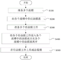
In the present embodiment, as shown in fig. 11, the batch coating method may include: preparing a plurality of liquid tanks 121 (step S100); supplying the coating solution to each liquid bath 121 (step S200); preparing a plurality of workpieces 2 to be coated (step S300); immersing each workpiece 2 to be coated in the coating solution in each liquid tank 121 and leaving from the coating solution in each liquid tank 121 (step S400); a coating film is formed on each of the workpieces 2 to be coated (step S500). Thereby, a plurality of workpieces to be coated can be coated in batches and the coating consistency can be improved favorably.
In some examples, the order of execution of step S100, step S300, step S400, and step S500 may not be required. For example, step S100 and step S300 may be performed simultaneously.
In some examples, in step S100, the shapes of the plurality of liquid tanks 121 may be the same. Thereby, a plurality of workpieces to be coated can be coated in batches and the coating consistency is improved. In some examples, a plurality of liquid tanks 121 having the same shape may be prepared by the coating apparatus 1 according to the examples of the present disclosure.
In some examples, in step S100, the liquid tank 121 may include a groove body 1211 having an accommodation space. In some examples, the liquid bath 121 may include an opening portion 1212 connected with the groove portion 1211. In some examples, the cross-sectional area of the opening 1212 may be greater than the cross-sectional area of the slot 1211. Therefore, the utilization rate of the coating liquid can be improved.
In some examples, in step S100, the plurality of liquid baths 121 may be arranged at the same level. In some examples, the liquid tanks 121 located on the same plane may be prepared by the coating apparatus 1 according to the examples of the present disclosure. This can contribute to improvement in coating film uniformity.
In some examples, a coating solution may be prepared prior to step S200. In some examples, the coating solution may be stirred to obtain a uniform coating solution. This can contribute to improvement in coating film uniformity.
In some examples, step S200 may be performed after preparing the coating solution. In step S200, a predetermined volume of coating solution may be supplied to each liquid bath 121. In some examples, a predetermined volume of coating liquid may be supplied to each liquid bath 121 by the coating apparatus 1 according to the examples of the present disclosure. This can contribute to improvement in coating film uniformity.
In some examples, in step S200, the volumes of the coating solutions contained in the respective liquid tanks 121 may be uniform. This can contribute to improvement in coating uniformity.
In some examples, in step S200, a predetermined volume of coating solution may be simultaneously supplied to each of the liquid baths 121, respectively.
In some examples, in step S300, the number of the plurality of workpieces 2 to be film-coated may coincide with the number of the liquid tanks 121.
In some examples, step S300 may be performed after supplying the coating solution into the liquid bath 121. In step S300, a plurality of workpieces 2 to be coated may be fixed.
In some examples, a plurality of workpieces 2 to be film-coated may be fixed at the same level. This can contribute to improvement in coating film uniformity. In some examples, a plurality of workpieces 2 to be coated can be fixed on the same horizontal plane by the coating apparatus 1 according to the examples of the present disclosure.
In some examples, in step S300, the plurality of workpieces to be film coated 2 that are fixed may be aligned with the respective liquid tanks 121. For example, a plurality of liquid tanks 121 may be arranged at the same level, and a plurality of workpieces 2 to be film-coated may be fixed at the same level and positioned directly above the liquid tanks 121 with the plurality of fixed workpieces 2 to be film-coated aligned with the liquid tanks 121. In some examples, a plurality of workpieces 2 to be coated that are fixed may be aligned to the respective liquid tanks 121 by the coating apparatus 1 according to the examples of the present disclosure.
In some examples, step S400 may be performed after preparing the coating solution and the workpiece 2 to be coated. In step S400, each workpiece 2 to be coated may be immersed in the coating solution in each liquid tank 121 and separated from the coating solution in each liquid tank 121 at the same time. This can contribute to improvement in coating film uniformity.
In some examples, in step S400, each workpiece 2 to be coated may be aligned with each liquid bath 121 before the workpiece 2 to be coated is immersed in the coating liquid in the liquid bath 121. In some examples, each workpiece 2 to be coated can be aligned to each liquid bath 121 by the coating apparatus 1 according to the examples of the present disclosure.
In some examples, in step S400, each workpiece 2 to be coated may remain in the coating solution for a certain period of time (for example, it may remain for 30S, 1min, 2min or 5min) after being immersed in the coating solution in each liquid tank 121, and then leave the coating solution. The duration of the immersed state after the film-coating work 2 is immersed in the film-coating liquid may be referred to as a dwell time.
In some examples, the residence time may be adjusted according to the properties of the coating solution. For example, when the viscosity of the coating solution is high, the residence time may be appropriately adjusted, such as increasing the residence time from 1min to 5 min.
In some examples, the residence time of each workpiece 2 to be film-coated immersed in the coating liquid in each liquid bath 121 may be uniform. The coating equipment 1 according to the disclosed example can make the retention time of each workpiece 2 to be coated immersed in the coating liquid consistent.
In some examples, in step S400, the speed of immersing each workpiece 2 to be coated in the coating solution may be uniform. For example, in some examples, the work 2 to be coated may be immersed in the coating solution by dipping the work 2 to be coated downward, and the speed of dipping downward for each work 2 to be coated may be uniform. This can contribute to improvement in coating uniformity. In some examples, the coating apparatus 1 according to the examples of the present disclosure can make the speed of immersing each workpiece 2 to be coated in the coating solution uniform.
In some examples, in step S400, the depth of immersion of each workpiece 2 to be coated in the coating solution may be uniform. This can contribute to improvement in coating film uniformity. In some examples, the coating apparatus 1 according to the examples of the present disclosure can make the depth of each workpiece 2 to be coated immersed in the coating solution uniform.
In some examples, in step S400, the region to be coated 23 may be completely immersed in the coating solution while each workpiece to be coated 2 is immersed in the coating solution.
In some examples, in step S400, the speed of each workpiece 2 to be coated leaving the coating solution may be uniform. For example, in some examples, the workpiece 2 to be coated may be separated from the coating solution by pulling the workpiece 2 to be coated upward, and the speed of pulling upward may be uniform for each workpiece 2 to be coated. This can contribute to improvement in coating film uniformity. In some examples, the speed of each workpiece 2 to be coated leaving the coating liquid can be consistent by the coating device 1 according to the disclosed examples.
In some examples, step S500 may be performed after the workpiece 2 to be coated leaves the coating solution. In step S500, the coating solution on the workpiece 2 to be coated may be dried for a period of time to form a coating film on the workpiece 2 to be coated. The time from when the coating solution is removed from the workpiece 2 to be coated to when the coating solution is dried to form a coating film on the workpiece 2 to be coated may be referred to as a drying time.
In some examples, in step S500, the temperature of the drying environment of the workpiece 2 to be film-coated may be adjusted. In this case, the speed at which the coating solution on the workpiece 2 to be coated forms a coating film can be adjusted by adjusting the temperature, and thus, the coating efficiency can be advantageously improved. In some examples, the temperature of the drying environment of a plurality of workpieces 2 to be coated can be adjusted by the coating apparatus 1 according to the examples of the present disclosure. For example, the temperature of the drying environment of the workpiece 2 to be coated can be adjusted to 25 ℃, 30 ℃, 35 ℃ or 40 ℃ by the coating apparatus 1 according to the examples of the present disclosure.
In some examples, forming a coating film on the workpiece 2 to be film-coated may proceed to step S400. In other words, steps S400 and S500 may be performed in a loop.
In some examples, the number of cycles of steps S400 and S500 may be 1, 2, 3, 4, 5, or 6.
In some examples, the number of cycles may be adjusted according to actual needs. For example, in some examples, a coating film having a thickness of 1mm may be formed on the workpiece 2 to be coated after 1 cycle of steps S400 and S500 is performed, and a coating film having a thickness of 2mm may be formed on the workpiece 2 to be coated after 2 cycles of steps S400 and S500 is performed. In this case, the thickness of the coating film formed on the surface of the workpiece 2 to be coated can be adjusted by adjusting the number of cycles, whereby the coating film of a predetermined thickness can be formed on the workpiece 2 to be coated.
As described above, in the present disclosure, the work 2 to be coated may be coated using a batch coating method.
While the present disclosure has been described in detail in connection with the drawings and examples, it should be understood that the above description is not intended to limit the disclosure in any way. Those skilled in the art can make modifications and variations to the present disclosure as needed without departing from the true spirit and scope of the disclosure, which fall within the scope of the disclosure.
Claims (10)
1. A mass coating apparatus for improving consistency is characterized in that,
comprises a fixing mechanism, a liquid containing mechanism, a liquid injection mechanism and a control device; the fixing mechanism is provided with a plurality of fixing parts for fixing a workpiece to be coated with a film; the liquid containing mechanism is provided with a plurality of liquid tanks which are arranged side by side and are used for containing the coating liquid in the same shape, each liquid tank comprises a tank body part with a containing space and an opening part connected with the tank body part, the cross section area of the opening part is larger than that of the tank body part, and the liquid containing mechanism and the fixing mechanism can move relatively; the liquid injection mechanism is provided with a liquid storage part for containing coating liquid and an infusion part communicated with the liquid storage part and used for supplying the coating liquid, and the liquid injection mechanism and the liquid containing mechanism can move relatively; the control device is configured to control at least the relative movement between the fixing mechanism and the liquid containing mechanism and the relative movement between the liquid containing mechanism and the liquid injection mechanism, and control the liquid injection mechanism to supply the coating liquid through the infusion part; when a workpiece to be coated fixed on the fixing mechanism is coated, the control device controls the liquid injection mechanism and the liquid containing mechanism to move relatively so that the infusion part is aligned with the liquid tank and controls the infusion part to supply coating liquid with a preset volume into the liquid tank; and the control device controls the liquid containing mechanism and the fixing mechanism to move relatively so that the workpiece to be coated, which is fixed on the fixing mechanism, is immersed into the coating liquid in the liquid tank and separated from the coating liquid in the liquid tank, and a coating film with a preset thickness is formed on the workpiece to be coated.
2. The mass coating apparatus according to claim 1, wherein:
the predetermined volume is not greater than the volume of the accommodating space, and the predetermined volume is less than or equal to 100 μ L.
3. The mass coating apparatus according to claim 1, wherein:
the opening part is by upper end to lower extreme convergent hourglass shape, cell body portion connect in the lower extreme of opening part.
4. The mass coating apparatus according to claim 1, wherein:
the groove body portion comprises a main body area and a bottom area, the main body area is cylindrical, and the bottom area is hemispherical.
5. The mass coating apparatus according to claim 1, wherein:
the liquid containing mechanisms are arranged in an array manner.
6. The mass coating apparatus according to claim 1, wherein:
the coating device further comprises a liquid injection chamber and a coating chamber, wherein the liquid injection mechanism supplies coating liquid to the liquid containing mechanism, and a workpiece to be coated, which is fixed on the fixing mechanism, is immersed in the coating liquid in the liquid tank in the coating chamber.
7. The mass coating apparatus according to claim 1, wherein:
the liquid injection mechanism further comprises a piston which is arranged in the liquid storage part and can move along the length direction of the liquid storage part, the piston is connected with an actuating part, the actuating part actuates the piston to move along the length direction of the liquid storage part, the actuating part is connected with the control device and is controlled by the control device, and the control device controls the actuating distance and the actuating direction of the actuating part so as to supply the coating liquid with a preset volume to the liquid tank through the infusion part.
8. The mass coating apparatus according to claim 1, wherein:
the workpiece to be coated is provided with a first fixing area, a second fixing area and a region to be coated, wherein the first fixing area, the second fixing area and the region to be coated are located on the same plane and are sequentially connected, the first fixing area and the second fixing area are flaky, and the region to be coated is needle-shaped.
9. The mass coating apparatus according to claim 8, wherein:
the fixing part is provided with a first limiting groove matched with the first fixing area and a second limiting groove matched with the second fixing area, the first limiting groove is matched with the first fixing area to limit the area to be coated in the vertical direction, and the second limiting groove is matched with the second fixing area to limit the area to be coated in the horizontal direction, so that the area to be coated is limited at a preset position.
10. A batch coating method for improving consistency is characterized in that:
the method comprises the following steps: preparing a plurality of liquid tanks with the same shape, and respectively supplying coating liquid with preset volume to each liquid tank; preparing a plurality of workpieces to be coated, simultaneously immersing each workpiece to be coated into the coating liquid in each liquid tank respectively and separating from the coating liquid in each liquid tank, wherein the immersion depths of the workpieces to be coated into the coating liquid are consistent, so that a coating film with a preset thickness is formed on each workpiece to be coated; the liquid tank comprises a tank body part with an accommodating space and an opening part connected with the tank body part, and the cross sectional area of the opening part is larger than that of the tank body part.
Priority Applications (6)
| Application Number | Priority Date | Filing Date | Title |
|---|---|---|---|
| CN202110291066.0A CN115106245B (en) | 2021-03-18 | 2021-03-18 | Batched coating equipment and batched coating method |
| PCT/CN2021/133304 WO2022193720A1 (en) | 2021-03-18 | 2021-11-25 | Batch film-coating device and batch film-coating method |
| EP21931294.9A EP4289517A4 (en) | 2021-03-18 | 2021-11-25 | Apparatus for batch film coating and method for batch film coating |
| US18/069,314 US12257598B2 (en) | 2021-03-18 | 2022-12-21 | Batch coating apparatus and batch coating method |
| US19/231,443 US20250296111A1 (en) | 2021-03-18 | 2025-06-07 | Batch coating apparatus and batch coating method |
| US19/231,441 US20250303437A1 (en) | 2021-03-18 | 2025-06-07 | Batch coating apparatus and batch coating method |
Applications Claiming Priority (1)
| Application Number | Priority Date | Filing Date | Title |
|---|---|---|---|
| CN202110291066.0A CN115106245B (en) | 2021-03-18 | 2021-03-18 | Batched coating equipment and batched coating method |
Publications (2)
| Publication Number | Publication Date |
|---|---|
| CN115106245A true CN115106245A (en) | 2022-09-27 |
| CN115106245B CN115106245B (en) | 2024-04-09 |
Family
ID=83321692
Family Applications (1)
| Application Number | Title | Priority Date | Filing Date |
|---|---|---|---|
| CN202110291066.0A Active CN115106245B (en) | 2021-03-18 | 2021-03-18 | Batched coating equipment and batched coating method |
Country Status (4)
| Country | Link |
|---|---|
| US (1) | US12257598B2 (en) |
| EP (1) | EP4289517A4 (en) |
| CN (1) | CN115106245B (en) |
| WO (1) | WO2022193720A1 (en) |
Cited By (1)
| Publication number | Priority date | Publication date | Assignee | Title |
|---|---|---|---|---|
| CN116809314A (en) * | 2023-06-28 | 2023-09-29 | 上海微创生命科技有限公司 | Film liquid container, film coating equipment and film coating method of implantable sensor |
Families Citing this family (2)
| Publication number | Priority date | Publication date | Assignee | Title |
|---|---|---|---|---|
| EP4052515A1 (en) * | 2019-10-29 | 2022-09-07 | Telefonaktiebolaget LM Ericsson (publ) | Target based control of synchronization signals in d2d communication |
| US12390827B1 (en) * | 2022-06-28 | 2025-08-19 | Biocoat, Incorporated | Lumen coating method and apparatus |
Citations (12)
| Publication number | Priority date | Publication date | Assignee | Title |
|---|---|---|---|---|
| JP2001000907A (en) * | 1999-06-21 | 2001-01-09 | Toray Ind Inc | Method and apparatus for application, plasma display, and method and apparatus for producing member for display |
| JP2004122110A (en) * | 2002-07-30 | 2004-04-22 | Sony Corp | Dip coating tank, dip coating device and dip coating method |
| US20090017210A1 (en) * | 2007-07-09 | 2009-01-15 | Andrianov Alexander K | Methods and systems for coating a microneedle with a dosage of a biologically active compound |
| US20130209660A1 (en) * | 2010-10-27 | 2013-08-15 | Teijin Limited | Micro-needle coating method |
| CN103934149A (en) * | 2014-04-10 | 2014-07-23 | 台州迈得医疗工业设备股份有限公司 | Device and process for silicifying surface of needle tube of medical needle |
| CN103993252A (en) * | 2014-05-30 | 2014-08-20 | 贵州雅光电子科技股份有限公司 | Diode tin-immersion device and using method thereof |
| CN104941859A (en) * | 2015-06-25 | 2015-09-30 | 浙江凯立特医疗器械有限公司 | Film coating equipment for sensor |
| CN107649333A (en) * | 2017-10-31 | 2018-02-02 | 上海理工大学 | A kind of seal wire dipping system |
| CN209087977U (en) * | 2018-10-10 | 2019-07-09 | 安徽赛尔新能源科技有限公司 | A kind of priming device of 14 serial lithium battery production |
| CN209697331U (en) * | 2019-02-22 | 2019-11-29 | 三诺生物传感股份有限公司 | A kind of biosensor film tooling |
| CN211577177U (en) * | 2019-10-24 | 2020-09-25 | 佛山市中医院 | Novel movable programmable multifunctional sample adding system |
| CN214682591U (en) * | 2021-03-18 | 2021-11-12 | 深圳硅基传感科技有限公司 | Batch coating equipment |
Family Cites Families (11)
| Publication number | Priority date | Publication date | Assignee | Title |
|---|---|---|---|---|
| US2803257A (en) * | 1955-03-10 | 1957-08-20 | Joseph M Cozzoli | Ampul washing device |
| US4358483A (en) * | 1981-12-16 | 1982-11-09 | The D. L. Auld Company | Glass container selected base coating process |
| US5354379A (en) * | 1993-02-08 | 1994-10-11 | Minnesota Mining And Manufacturing Company | Apparatus for applying a protective coating to a film strip |
| US5725667A (en) * | 1996-03-01 | 1998-03-10 | Xerox Corporation | Dip coating apparatus having a single coating vessel |
| JP2000102759A (en) * | 1998-07-31 | 2000-04-11 | Toray Ind Inc | Coating method and coating device as well as production of plasma display and member for display and apparatus for production thereof |
| DE10209908C1 (en) * | 2002-03-07 | 2003-08-14 | Reinhardt Gmbh Ernst | Surface coating system has drums composed of two mirror-symmetrical half-shells which can be moved along horizontal axis |
| US7381273B2 (en) * | 2005-03-15 | 2008-06-03 | Curingsolutions, Llc | Apparatus and method for coating medical devices |
| US7597937B2 (en) * | 2006-03-21 | 2009-10-06 | Harland Medical Systems, Llc | Coating apparatus for flimsy members with alignment means |
| WO2009035457A1 (en) * | 2007-09-13 | 2009-03-19 | Reilly Dillon | Dip coating apparatus with height adjustable coating tubes and method of coating |
| WO2019050962A1 (en) * | 2017-09-05 | 2019-03-14 | Harland Medical Systems, Inc. | A coating apparatus with an automatic fluid level system, and methods of using the same |
| CN109848002B (en) * | 2019-03-15 | 2023-09-19 | 浙江大学城市学院 | Film coating machine |
-
2021
- 2021-03-18 CN CN202110291066.0A patent/CN115106245B/en active Active
- 2021-11-25 EP EP21931294.9A patent/EP4289517A4/en active Pending
- 2021-11-25 WO PCT/CN2021/133304 patent/WO2022193720A1/en not_active Ceased
-
2022
- 2022-12-21 US US18/069,314 patent/US12257598B2/en active Active
Patent Citations (12)
| Publication number | Priority date | Publication date | Assignee | Title |
|---|---|---|---|---|
| JP2001000907A (en) * | 1999-06-21 | 2001-01-09 | Toray Ind Inc | Method and apparatus for application, plasma display, and method and apparatus for producing member for display |
| JP2004122110A (en) * | 2002-07-30 | 2004-04-22 | Sony Corp | Dip coating tank, dip coating device and dip coating method |
| US20090017210A1 (en) * | 2007-07-09 | 2009-01-15 | Andrianov Alexander K | Methods and systems for coating a microneedle with a dosage of a biologically active compound |
| US20130209660A1 (en) * | 2010-10-27 | 2013-08-15 | Teijin Limited | Micro-needle coating method |
| CN103934149A (en) * | 2014-04-10 | 2014-07-23 | 台州迈得医疗工业设备股份有限公司 | Device and process for silicifying surface of needle tube of medical needle |
| CN103993252A (en) * | 2014-05-30 | 2014-08-20 | 贵州雅光电子科技股份有限公司 | Diode tin-immersion device and using method thereof |
| CN104941859A (en) * | 2015-06-25 | 2015-09-30 | 浙江凯立特医疗器械有限公司 | Film coating equipment for sensor |
| CN107649333A (en) * | 2017-10-31 | 2018-02-02 | 上海理工大学 | A kind of seal wire dipping system |
| CN209087977U (en) * | 2018-10-10 | 2019-07-09 | 安徽赛尔新能源科技有限公司 | A kind of priming device of 14 serial lithium battery production |
| CN209697331U (en) * | 2019-02-22 | 2019-11-29 | 三诺生物传感股份有限公司 | A kind of biosensor film tooling |
| CN211577177U (en) * | 2019-10-24 | 2020-09-25 | 佛山市中医院 | Novel movable programmable multifunctional sample adding system |
| CN214682591U (en) * | 2021-03-18 | 2021-11-12 | 深圳硅基传感科技有限公司 | Batch coating equipment |
Cited By (1)
| Publication number | Priority date | Publication date | Assignee | Title |
|---|---|---|---|---|
| CN116809314A (en) * | 2023-06-28 | 2023-09-29 | 上海微创生命科技有限公司 | Film liquid container, film coating equipment and film coating method of implantable sensor |
Also Published As
| Publication number | Publication date |
|---|---|
| CN115106245B (en) | 2024-04-09 |
| WO2022193720A1 (en) | 2022-09-22 |
| US20230182163A1 (en) | 2023-06-15 |
| EP4289517A1 (en) | 2023-12-13 |
| EP4289517A4 (en) | 2025-03-19 |
| US12257598B2 (en) | 2025-03-25 |
Similar Documents
| Publication | Publication Date | Title |
|---|---|---|
| CN214682591U (en) | Batch coating equipment | |
| CN115106245A (en) | Batch coating equipment and batch coating method | |
| US8322193B2 (en) | Transdermal diffusion cell testing arrangements and methods | |
| KR101910653B1 (en) | Cell structure production device | |
| JP2020512529A (en) | Automated tissue section capture, indexing and storage system | |
| EP1141704B1 (en) | Interface patch clamping | |
| CN107922907B (en) | Object moving method and object moving device | |
| EP2139613B1 (en) | Method of manufacturing coated needle electrodes | |
| WO2016020992A1 (en) | Culture apparatus, culture method using same, and method for selecting aggregated cell mass | |
| JP2023058741A (en) | Sample creation device and sample creation system | |
| JP2022091788A (en) | Blood coagulation data measuring device, its usage, connecting members and supports | |
| US20070111298A1 (en) | Sample depositing device for a cell sorter | |
| US7465558B2 (en) | Perfusion system and apparatus for automated multi-channel patch-clamp recordings utilizing inside-out whole-cell configuration | |
| JP6663555B2 (en) | Cell three-dimensional structure manufacturing equipment | |
| JP2883294B2 (en) | Biological tissue processing device and reagent processing unit | |
| US20250296111A1 (en) | Batch coating apparatus and batch coating method | |
| US20250018389A1 (en) | Detection chip assembly tool, liquid injection apparatus and method, electronic device, and medium | |
| JP2014055827A (en) | Permeation speed measuring device, and sample holding tool used for the same | |
| JP3145361B2 (en) | Dispensing device | |
| EP4016042A1 (en) | Specimen preparation apparatus | |
| JP6663556B2 (en) | Cell three-dimensional structure manufacturing equipment | |
| US10408816B2 (en) | Method and device for automatically determining the position of a microsystem for manipulating a spherical microobject | |
| CN216559449U (en) | Medical catheter friction test system | |
| US20250123476A1 (en) | Microscope Enabled 3D Bioprinting System | |
| US20140042039A1 (en) | Apparatuses and methods for conditioning and reorienting components of an electrophysiology measurement system |
Legal Events
| Date | Code | Title | Description |
|---|---|---|---|
| PB01 | Publication | ||
| PB01 | Publication | ||
| SE01 | Entry into force of request for substantive examination | ||
| SE01 | Entry into force of request for substantive examination | ||
| GR01 | Patent grant | ||
| GR01 | Patent grant |