Adjustable switch for drawer booster
Technical Field
The invention relates to the field of switches, in particular to an adjustable switch for a drawer booster.
Background
In the prior art, a drawer booster needs to be arranged inside a drawer cabinet body, and then a drawer is pushed to enable a rear panel of the drawer to press a switch on the drawer booster, so that the drawer booster pushes out the drawer; however, in the prior art, the switch on the drawer booster is fixed and unadjustable, and the switch on the drawer booster and the drawer rear panel of the drawer inside the drawer cabinet with different styles are not fixed, so that the position of the drawer needs to be adjusted, the difficulty of assembly and debugging is huge, and the installation is inconvenient.
Disclosure of Invention
To solve the above problems, the present invention provides: an adjustable switch for a drawer booster can realize the position adjustment of a switch module by manually pulling the switch module, and after the position is determined, a movable locking device can be rotated to lock the tail end of the movable locking device to a first movable gear, so that a rack is immovable, and the position of the switch module can be fixed; can be with adjustment switch module and drawer rear panel distance, the repeated debugging of wanting when avoiding the installation.
In order to achieve the purpose, the invention adopts the technical scheme that: an adjustable switch for a drawer booster comprises a cover body, a switch module and a movable locking device, wherein an installation notch is formed in the side face of the cover body, a rack is arranged at the bottom of the switch module, and a first movable gear meshed with the rack is arranged inside the cover body; the switch module penetrates through the mounting notch along the axis direction of the rack and drives the first movable gear to rotate; and one end of the movable locking device extends into the cover body, and the tail end of the movable locking device is clamped or separated from the first movable gear by rotating the movable locking device.
Further, the movable locking device comprises an adjusting knob positioned outside the cover body and a locking rod of a J-shaped structure positioned inside the cover body; wherein one end of the adjusting knob extends into the cover body and is connected with one end of the locking rod, the other end of the locking rod is provided with a latch used for limiting the rotation of the first movable gear, and the adjusting knob is rotated to enable the latch to be clamped or separated from the first movable gear.
Furthermore, the one end that adjust knob extends to in the lid is first connecting portion, and the cross section of this first connecting portion is "ten" style of calligraphy structure, just the one end of locking lever is the second connecting portion, has seted up in this second connecting portion with the spread groove of connecting portion adaptation, connecting portion are pegged graft and are realized the dress in the spread groove.
Further, be provided with the fixed baffle that two symmetries set up in the lid, and two fixed baffles enclose into a locking groove, and wherein the locking lever is placed in the locking inslot, and second connecting portion are located between locking groove and the lid inside wall, and the external diameter of second connecting portion is greater than the width in locking groove.
Furthermore, a first alignment mark is arranged on the outer side wall of the cover body, and a second alignment mark is arranged on the adjusting knob.
Further, the switch module comprises a switch box and a control switch, wherein the switch box comprises a switch box body, a switch box body and a return spring arranged in the switch box body, and the rack is connected with the bottom of the switch box body; the one end box body of reset spring is connected, and the other end is connected with the switch box body, the switch box body moves and triggers the control switch who is located switch box body inside toward the switch box body, just reset spring is in compression state.
Furthermore, a plurality of movable pins are arranged at the bottom of the switch box body, a plurality of clamping holes are formed in the bottom of the switch box body, the switch box body penetrates through the clamping holes through the movable pins, and clamping hooks are arranged at the tail ends of the movable pins; the bottom of switch box body still is provided with the guide post, the guiding hole has been seted up to the bottom of switch box body, and wherein reset spring overlaps and establishes at the guide post, and the guide post activity is furnished with in the guide hole.
Furthermore, the lateral wall of switch box bottom still is provided with the stopper, and this stopper supports the inner wall of ending at the installation breach and realizes spacingly.
Furthermore, a first shaft cylinder and a second shaft cylinder are convexly arranged inside the cover body, wherein the first movable gear is movably sleeved on the first shaft cylinder, a second movable gear is movably sleeved on the second shaft cylinder, and one side of the rack, which is far away from the first movable gear, is meshed with the second movable gear.
The locking device further comprises a positioning cover plate, wherein a first positioning pin and a second positioning pin are arranged at the bottom of the positioning cover plate, the first positioning pin is inserted into the first shaft cylinder, the second positioning pin is inserted into the second shaft cylinder, and the locking rod, the rack, the first movable gear and the second movable gear are covered by the positioning cover plate.
The invention has the beneficial effects that: when a booster product is installed, the drawer rear panel is ensured to be fully contacted with a product switch in the application, the realization of functions can be ensured, the styles of drawers are different, the space behind the drawers is different, the position of the product installed in the drawer rear panel is determined, the adjustable switch of the application is added, the position of the switch module can be adjusted by manually pulling the switch module, and after the position is determined, the movable locking device can be rotated, namely, the tail end of the movable locking device is locked with the first movable gear, so that the rack is immovable, and the position of the switch module can be fixed; can be with adjustment switch module and drawer rear panel distance, the repeated debugging of wanting when avoiding the installation.
Drawings
Fig. 1 is a schematic structural view of the present invention.
Fig. 2 is a schematic structural view of the cover body in the present invention.
Fig. 3 is a schematic view of the construction of the movable locking device.
Fig. 4 is a schematic view of the structure of the adjusting screw.
Fig. 5 is a schematic view of the rack and the switch module.
Fig. 6 is a schematic structural view of the switch case.
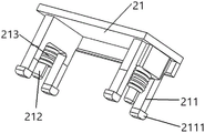
The reference numbers illustrate: the locking device comprises a cover body 1, an installation notch 11, a first fixed partition plate 12, a second fixed partition plate 13, a locking groove 14, a first shaft tube 15, a second shaft tube 16, a switch box body 21, a movable pin 211, a clamping hook 2111, a guide post 212, a return spring 213, a switch box body 22, a limiting block 221, a rack 3, a movable locking device 4, an adjusting knob 41, a second alignment mark 411, a first connecting part 412, a locking rod 42, a clamping tooth 421, a positioning cover plate 5, a first movable gear 6 and a second movable gear 7.
Detailed Description
Referring to fig. 1-6, the present invention relates to an adjustable switch for a drawer booster, which includes a cover 1, a switch module, and a movable locking device 4, wherein a side surface of the cover 1 is provided with an installation notch 11, a rack 3 is disposed at the bottom of the switch module, and a first movable gear 6 engaged with the rack 3 is disposed inside the cover 1; the switch module penetrates through the installation notch 11 along the axis direction of the rack 3 and drives the first movable gear 6 to rotate; and one end of the movable locking device 4 extends to the inside of the cover body 1, and the end of the movable locking device 4 is clamped or separated from the first movable gear 6 by rotating the movable locking device 4.
The product in the embodiment is actually used by matching with a drawer booster (No. CN208850917U), the device protected in the embodiment is used by combining with the drawer booster, namely, the switch module in the embodiment is electrically connected with the PLC controller, and when the drawer rear panel presses the switch module, the PLC controller can control the driving motor inside the drawer booster to act, so as to realize the effect of pushing the drawer. (since drawer boosters are prior art, the principle of operation has not been discussed redundantly with respect to their specific structure.)
When the drawer booster product is installed, the realization of functions can be ensured only by ensuring that the rear panel of the drawer is fully contacted with the product switch in the application, the styles of the drawer are different, the space behind the drawer is different, and then the position of the product installed inside the drawer booster product is required to be confirmed; the adjustable switch is added, the position of the switch module can be adjusted by manually pulling the switch module, and after the position is determined, the movable locking device 4 can be rotated, namely, the tail end of the movable locking device is locked with the first movable gear 6, so that the rack 3 is immovable, and the position of the switch module can be fixed; can be with adjustment switch module and drawer rear panel distance, the repeated debugging of wanting when avoiding the installation.
Further, the movable locking device 4 comprises an adjusting knob 41 positioned outside the cover body 1, a locking rod 42 of a "J" type structure positioned inside the cover body 1; one end of the adjusting knob 41 extends into the cover body 1 and is connected with one end of the locking lever 42, the other end of the locking lever 42 is provided with a latch 421 for limiting the rotation of the first movable gear 6, and the adjusting knob 41 is rotated to enable the latch 421 to be latched or disengaged with the first movable gear 6. In the present application, the latch 421 at the end of the locking lever 42 of the "J" type structure locks the first movable gear 6, and locks the position of the switch module, and the structure is simple and the operation is easy.
Further, one end of the adjusting knob 41 extending into the lid body 1 is a first connecting portion 412, the cross section of the first connecting portion 412 is a cross-shaped structure, one end of the locking lever 42 is a second connecting portion, a connecting groove adapted to the connecting portion is formed in the second connecting portion, and the connecting portion is inserted into the connecting groove to be assembled. In order to realize the detachable connection between the adjusting knob 41 and the locking rod 42 through the first connecting portion 412 and the second connecting portion, the maintenance is convenient, and meanwhile, the cross section of the first connecting portion 412 is in a cross-shaped structure, so that the slipping phenomenon between the first connecting portion 412 and the second connecting portion is avoided.
Further, be provided with the fixed baffle that two symmetries set up in the lid 1: first fixed baffle 12 and the fixed baffle 13 of second, and first fixed baffle 12 and the fixed baffle 13 of second enclose into a locking groove 14, and wherein locking lever 42 is placed in locking groove 14, and the second connecting portion are located between locking groove 14 and the lid 1 inside wall, and the external diameter of second connecting portion is greater than the width that locks groove 14. In this embodiment, the locking rod 42 is placed in the locking groove 14 to stabilize the position thereof and prevent the left and right deviation, and the outer diameter of the second connecting portion is larger than the width of the locking groove 14, and the second connecting portion is located between the locking groove 14 and the inner side wall of the cover body 1, so as to prevent the locking rod 42 from shifting in the up-down direction.
Further, a first alignment mark is provided on the outer side wall of the cover body 1, and a second alignment mark 411 is provided on the adjusting knob 41. The first alignment mark and the second alignment mark 411 function to remind the user of the locked state or the unlocked state.
Further, the switch module comprises a switch box and a control switch, wherein the switch box comprises a switch box body 22, a switch box body 21 and a return spring 213 arranged in the switch box body 21, and the rack 3 is connected with the bottom of the switch box body 22; the one end box body of reset spring 213 is connected, and the other end is connected with switch box body 21, switch box body 21 moves and triggers the control switch who is located switch box body 22 inside toward switch box body 22, just reset spring 213 is in compression state. Wherein be used for through promoting the drawer rear panel, then make the drawer rear panel move toward switch box body 21, and then promote switch box body 21 and move toward switch box body 22 direction, trigger the control switch who is located switch box body 22 inside simultaneously, then make the inside driving motor action of PLC controller control drawer boost motor, and then realize the effect that promotes the drawer, after the drawer rear panel is released, under reset spring 213 spring effort, with switch box body 21 toward outside promotion realization reset again, wait for next trigger control switch.
Further, a plurality of movable pins 211 are arranged at the bottom of the switch box body 21, a plurality of clamping holes are formed at the bottom of the switch box body 22, the switch box body 21 penetrates through the clamping holes through the movable pins 211, and a clamping hook 2111 is arranged at the tail end of each movable pin 211; the bottom of the switch box body 21 is further provided with a guide post 212, the bottom of the switch box body 22 is provided with a guide hole, wherein the reset spring 213 is sleeved on the guide post 212, and the guide post 212 is movably assembled in the guide hole.
In this embodiment, in order to avoid the excessive acting force of the return spring 213 from completely separating the switch box body 21 from the switch box body 22, the hook 2111 at the end of the movable leg 211 will be stopped at the locking hole, so as to avoid the above situation; the guide post 212 is provided to ensure that the switch box 21 moves along a designated direction without deviation.
Further, the outer side wall of the bottom of the switch box 22 is further provided with a limiting block 221, and the limiting block 221 abuts against the inner wall of the installation notch 11 to realize limiting. In this embodiment, the switch box 22 can be prevented from falling out of the installation notch 11 by providing the stopper 221.
Further, a first shaft barrel 15 and a second shaft barrel 16 are convexly arranged inside the cover body 1, wherein the first movable gear 6 is movably sleeved on the first shaft barrel 15, and a second movable gear 7 is movably sleeved on the second shaft barrel 16, wherein one side of the rack 3, which is far away from the first movable gear 6, is meshed with the second movable gear 7. In this embodiment, the first movable gear 6 and the second movable gear 7 are provided for guiding the moving direction of the rack 3.
Further, the locking device further comprises a positioning cover plate 5, wherein a first positioning pin and a second positioning pin are arranged at the bottom of the positioning cover plate 5, the first positioning pin is inserted into the first shaft cylinder 15, the second positioning pin is inserted into the second shaft cylinder 16, and the locking rod 42, the rack 3, the first movable gear 6 and the second movable gear 7 are covered by the positioning cover plate 5. In this embodiment, the positioning cover covers the locking rod 42, the rack 3, the first movable gear 6, and the second movable gear 7, so as to prevent the locking rod 42, the rack 3, the first movable gear 6, and the second movable gear 7 from moving in the vertical direction.
The above embodiments are only for describing the preferred embodiments of the present invention, and are not intended to limit the scope of the present invention, and various modifications and improvements made to the technical solution of the present invention by those skilled in the art without departing from the spirit of the design of the present invention should fall within the protection scope defined by the claims of the present invention.